LEVEL MEASUREMENT - Control Global
25
SPECIAL REPORT LEVEL MEASUREMENT PART I
Transcript of LEVEL MEASUREMENT - Control Global
SPECIAL REPORT
LEVEL MEASUREMENT
PART I

Acromag.com 877-295-7066
MADE IN USA
ISO9001AS9100
IECEx
Visit acromag.com/xmittersTO LEARN MOREYou can depend on Acromag for all
your monitoring and control solutions.
Single/Dual-Channel Isolated Transmitters and Signal
Splitters Guarantee a Dependable Value
Accomplish more in less time with easy configuration via USB with Windows® software or Agility App™ for Android.
• TT Series: Thin 2 or 4-wire transmitters and isolators with a wide variety of input, output, and power configurations for broad flexibility.
• DT Series: Dual-channel transmitters that offer a cost-effective and space-saving solution to interface a variety of process and sensor signals to your control system.
• SP Series: Isolated signal splitters offering precise I/O scalability of input sensor/signals and dual outputs.
These collections of signal conditioners are ideal for single or hundreds of I/O points.
Acromag guarantees performance to meet or exceed published specs with exceptional personalized service before and after the sale.

Make sense of sensitive level . . . . . . . . . . . . . . . . . . . . . . . . . . . . . . . . . . . . . . . . . . . . . . . . . . . . . . . . 5
Bulk solids go back to school . . . . . . . . . . . . . . . . . . . . . . . . . . . . . . . . . . . . . . . . . . . . . . . . . . . . . . 10
Differential pressure missteps . . . . . . . . . . . . . . . . . . . . . . . . . . . . . . . . . . . . . . . . . . . . . . . . . . . . . . 17
Eccentric butterfly valves and errant dp cells . . . . . . . . . . . . . . . . . . . . . . . . . . . . . . . . . . . . . . . . 22
AD INDEXAcromag . . . . . . . . . . . . . . . . . . . . . . . . . . . . . . . . . . . . . . . . . . . . . . . . . . . . . . . . . . . . . . . . . . . . . . . . . . 2
Endress+Hauser . . . . . . . . . . . . . . . . . . . . . . . . . . . . . . . . . . . . . . . . . . . . . . . . . . . . . . . . . . . . . . . . . . . 4
Hawk Measurement . . . . . . . . . . . . . . . . . . . . . . . . . . . . . . . . . . . . . . . . . . . . . . . . . . . . . . . . . . . . . . . . 9
Krohne . . . . . . . . . . . . . . . . . . . . . . . . . . . . . . . . . . . . . . . . . . . . . . . . . . . . . . . . . . . . . . . . . . . . . . . . . . 16
Lumenite Control Technology . . . . . . . . . . . . . . . . . . . . . . . . . . . . . . . . . . . . . . . . . . . . . . . . . . . 15, 20
Massa Product Corp . . . . . . . . . . . . . . . . . . . . . . . . . . . . . . . . . . . . . . . . . . . . . . . . . . . . . . . . . . . . . . . 21
TABLE OF CONTENTS
www.controlglobal.com
Level Measurement, Part I 3

You are assured to get the best-fi t products, solutions and services for your specifi c requirements.
KNOWLEDGE+ KNOW-HOW
We understand how important it is to fi nd the right expertise for your industry application needs.
Do you want to learn more?www.endress.com/fwr30
Micropilot FWR30 – The cloud connected radar level sensor
• Transparency – full and secure access to information on asset and inventory status, from anywhere at any time
• Simplicity – from procurement to operations, simplifi ed commissioning, handling and processes
• Flexibility – suitable digital services defi ned by user needs, scalable from Netilion Value via Netilion Inventory to SupplyCare Hosting
• Reliability – precise measurement with wireless high-end 80Ghz sensor technology
Do you want to learn more? www.us.endress.com/fwr30

Headlinedeckbyline
Greg: It’s not well recognized that a sensitive level measurement can be extremely valu-
able . For inventory, a fraction of an inch change in level in a large-diameter tank is a lot of
material . For closure of material balances, these seemingly small changes in level can make
a huge difference in accounting and in process control of some key unit operations . For
crystallizers, evaporators and reactors, tight residence time control depends on an accurate
level measurement . Many multi-effect evaporators measure and control the product den-
sity in the last stage by manipulating a product or feed flow . These multi-effect evaporators
depend upon tight level control to make sure changes in flow in and out of each effect are
equal . For distillation columns where the distillate receiver level controller manipulates re-
flux flow, extremely tight level control enables much better temperature control, particularly
through inherent internal reflux control .
The most predominant level measurement uses a differential pressure (DP) transmitter . The
actual level, of course, depends on density . A second DP whose high and low connections
are always submersed or a Coriolis meter in a recirculation line can be used to measure den-
sity to correct the reading, but the DP sensitivity is not great . The accuracy seriously dete-
riorates due to problems and limitations of impulse lines, purges and capillary systems .
We have a situation for level similar to last month’s for mass flow, where Coriolis meters
had an order of magnitude better accuracy, much greater reliability, and much less vulner-
www.controlglobal.com
Level Measurement, Part I 5
Make sense of sensitive levelRadar offers increasing opportunities to improve control at a reasonable price .
by Greg Mcmillan

www.controlglobal.com
Level Measurement, Part I 6
ability to installation problems . The level
measurement is radar . Like Coriolis, radar
doesn’t depend on density (and thus asso-
ciated changes in composition), and while
the hardware cost is higher, the installation
cost and especial-ly the maintenance cost
is less . If you include the improvement in
process monitoring and control, the return
on investment is a no-brainer .
To help us get sensitive to sensitive level
measurement, we gain the insight and
knowledge offered by Jeff Blair, offer man-
ager for level, Schneider Electric .
Jeff: Thank you for inviting me to Con-
trol Talk, Greg . It’s an honor to be here . I
enjoyed reading your material along with
items from Hunter Vegas and many others .
Most of the free space radar (FSR) and
guided wave radar (GWR) applications we
see work flawlessly and get rave reviews .
However, a small number of radars are mis-
applied or not installed properly, so we’ve
been on an educational tour to help teach
the operators, technicians and engineers
about proper installation procedures and
how to get the best signal return . It’s for
reasons like these that there’s been a trend
for manufacturers to offer additional field
services (including startup services) for
radar . FSR and GWR are actually easier to
commission and use than most instruments,
as long as the end user follows proper ven-
dor instructions and/or has a rep or vendor
either onsite or on speed dial/Facetime/
Skype to help .
Greg: What equipment and process applica-
tion details do you need to know to correct-
ly specify and install FSR and GWR?
Jeff: When selecting a radar measurement,
the best thing to do is to gather the criteria
of process temperature, process pressure,
expected dielectric constant (Dk), mate-
rial requirements, available tank connec-
tions and economics . Next, work with your
favorite representative or manufacturer to
help narrow the choice of applicable radar
models . They can guide you on available
models and also help select special models
that can perform interface measurement
(GWR) or tolerate high temperatures and
pressures for applications such as steam
drum measurement .
All application parameters are important to
make sure the correct radar is selected and
that it performs for the lifecycle of the pro-
cess . Besides ensuring a Dk of 1 .1 or higher
(1 .5 preferred), the other most important
thing to consider when selecting radar is
to ensure proper selection of the cable, rod
or coaxial probe (GWR) or antenna (FSR) .
The reason is that those items and their
design and dimensions have a large part
in determining the overall maximum mea-
surement length, beam angle (FSR only),
and temperature and pressure limitations .
A close runner-up to the antenna selection

www.controlglobal.com
Level Measurement, Part I 7
is the proper choice of the physical instal-
lation location (i .e ., what distance from the
tank wall, ensuring location is away from
center of tank and any filling nozzles or
streams) on top of the tank, vessel, sump
pit or stilling well . The goal of proper
physical location of the radar is to eliminate
potential obstacles, and give the radar the
best possible chance at return signal . There
are fewer constraints and restrictions when
choosing an installation location for GWR as
the microwave energy always stays within a
radius of the probe .
Greg: What are the installation require-
ments you need to carefully address for
FSR and GWR?
Jeff: The beauty of both types of radar is
their simple installation techniques com-
pared with other types of level instrumenta-
tion . There are no requirements for process
tubing runs that are often re-quired for DP
level applications . Regarding GWR, pay
attention to ensure you have enough over-
head clearance to install a rod or coax unit .
It’s no different than ensuring overhead
coverage when installing a capacitance
probe or a magnetostrictive instrument .
And some of the probes come in segments,
so several short pieces may be assembled
together rather than a long 10- or 20-ft rod .
Cable antennas for GWR may need to be
secured to the bottom of the tank . If that’s
the case, there may be some potential for
confined space permits . FSR is a bit simpler
because it is non-contact; there’s no probe
or cable that extends down into the liquid .
Once those items are accounted for, both
FSR and GWR are simply screwed into
their respective process connections with
the face oriented in accordance with in-
structions .
Installing radar when the tank is empty is
advised . This allows the radar software to
take a snapshot of the tank and identify any
obstacles (e .g . baffles, ladders) that may
be interpreted as false level reflections . The
snapshot or tank mapping procedure allows
the user to blank out potential false echoes .
It’s worth noting that high-frequency (80
GHz) types of FSR have a narrow radar
beam that’s often able to avoid seeing ob-
stacles and potential disturbances, eliminat-
ing the need to map them out .
Greg: What do you need to know to cor-
rectly install FSR and GWR?
Jeff: In radar, the measurement is inferred
from distance, like how level is inferred from
head pressure when using DP level . The data
needed are three pieces of information:
1 . The tank height—from the process con-
nection of the radar to the tank (where
the radar signal generates) to the tank
bottom .
2 . The 4 mA or 0% level—this should nor-
mally be located at an offset from the
very bottom of the tank .

www.controlglobal.com
Level Measurement, Part I 8
3 . The 20 mA or 100% level—this should be
located below the flange and allow room
for the radar dead space . Each type of
radar requires a small amount of buffer
space either below the process connec-
tion or the horn (FSR only) .
Greg: When would you use ultrasonic in-
stead of radar level measurements?
Jeff: Cost-conscious consumers often
chose ultrasonic . Ultrasonic transmitters
using sound waves were about half the
cost of radar, and like radar, they perform
flawlessly if they’re applied and installed
properly . Now, in general, the average
price of process FSR and GWR have come
down, so that the price delta between
radar and ultrasonic closed . Price being
nearly equal, most users opt for radar as
it can handle higher temperatures and
pressures . Now, ultrasonic measurements’
primary advantage is that its unaffected
by Dk . One of the drawbacks to ultrasonic
used to be the buildup of condensation on
the transducer face . Recently, there’s been
some advancement in that field where
some ultrasonic measurements are bet-
ter able to shed condensation droplets to
make a reliable measurement .
For much more useful guidance and the “Top 10 things you don’t want to hear about a level loop,” visit www.controlglobal.com/articles/2019/make-sense-of-sensitive-level.

Hawk Measurement (HAWK) has designed and developed the world’s first Power over Ethernet (PoE)
in-plant and cloud-based asset monitoring system. For over 30 years, HAWK has successfully solved
difficult liquid and solid applications in a wide range of industries. Proudly made in USA and Australia.
SECURE AND RELIABLE
LEVEL MEASUREMENT
LOCAL AND WEB-BASED
TANK MONITORING
MONITOR INVENTORY
FROM ANYWHERE
www.hawkmeasurement.com | USA: +1 (888) 429-5538 | AU: +61 (0)3 9873 4750
Industry’s First
Power over Ethernet
Level Sensors
I N T E R F A C E L E V E L M A I N T E N A N C E F R E E L I Q U I D S A N D S O L I D S

Headlinedeckbyline
Liquids and gases are easy—or at least their characteristics and behaviors are bet-
ter understood . Granules, grains, pellets, powders and other particulate solids
are more varied and less studied, so their profiles often remain mysterious and
require further study to let users handle and process them with fewer problems and
greater effectiveness .
That’s the basic mission of the Bulk Solids Innovation Center (BSIC, https://bulk-solids .k-
state .edu) at Kansas State University in Salina, Kan . The center is the result of a collabora-
tive partnership of industry, education and government, and is reported to be the only
university-level research facility of its kind in North America . It examines the properties of
various bulk substances; tests them and how they’re handled and conveyed; develops re-
ports and solutions to improve storage and flow efficiency; and educates users and interns
about how to improve productivity .
BSIC consists of a two-story 13,000-square-foot building with six laboratories for university-
and industry-sponsored research, and training and conference rooms . Its laboratories include
a material properties testing lab with a complete range of instruments and a full-scale, bulk
solids testing bay (Figure 1) . Its bulk solids processing systems can perform feeding, weigh-
ing and scaling, silo blending and segregation, particulate air filtration, gravity flows and flow
aids . The center also has full-scale, dense- and dilute-phase, pneumatic conveying systems to
www.controlglobal.com
Level Measurement, Part I 10
Bulk solids go back to schoolThe Bulk Solids Innovation Center at Kansas State University researches and teaches users to optimize material handling
by Jim Montague

www.controlglobal.com
Level Measurement, Part I 11
research and solve issues related to bulk sol-
ids transport, such as attrition, segregation,
sizing, wear and energy consumption .
ORIGINS AND CHALLENGESEven though bulk solids account for 75-
80% of the ingredients and products
produced and transported worldwide, BSIC
reports formal education and research
are rare . The same goes for the persistent
challenges presented by slurries of mixed
liquids and solids, foams of differing con-
sistencies and layers of gases and liquids in
the same vessels .
“The center was organized about 10 years
ago by a group of people from the agri-
culture, food, chemical, plastics and phar-
maceutical manufacturers near here, who
lamented there was no place to study and
get educated about bulk solids because
they weren’t researched or taught at the
universities, so they began working with
Kansas State and local government,” says
Todd Smith, P .E ., business and strategy
manager at BSIC . “There are more re-
sources for liquids and gases historically
because users have worked with them
longer and know the equations for dealing
with them, and so they’re simpler to quan-
tify, present fewer variables and have more
predictable solutions . So, even though
there are more varieties of bulk solids,
they’re less studies and understood, many
BUILT FOR BULKFigure 1: The Bulk Solids Innovation Center (BSIC) at Kansas State University in Salina BSIC con-sists of a two-story, 13,000-square-foot building with six laboratories for university- and indus-try-sponsored research, and training and conference rooms. Its laboratories include a material properties testing lab with a complete range of instruments and a full-scale, bulk solids testing bay. Source: BSIC

www.controlglobal.com
Level Measurement, Part I 12
questions about them and their behavior
aren’t resolved, and there aren’t predict-
able solutions for many of them .”
After several years of organizing and se-
curing funding, BSIC’s founders built and
opened the center five years ago, integrat-
ed equipment from 25 donor companies,
and began studying the many variables as-
sociated with bulk solids . This research was
especially needed because characteristics
can vary if the same application is located
at different sites according changes in am-
bient conditions and environments .
“For instance, we recently worked with a
flame retardant that consisted of a sticky
material that flowed and performed okay
at one site but not at another,” says Kevin
Solofra, lab manager at BSIC . “We had to
ask if it was the setting, how the powder
was processed, or if it was how operators
were acting . Through testing and work-
ing with the customer, we discovered that
the powder’s characteristic were highly
dependent on the consolidation aspect of
the material . In another test, we were able
to reveal that a powder’s characteristics
varied based on storage humidity and tem-
perature . So, even though particle size was
consistent, the material flowed differently
due to environmental conditions .
“Level measurement of bulk solids is also
more challenging because filling and dis-
charging often creates unusual angles and
levels that shift, as well as dust in silos that
can affect readings .”
RESEARCH AND SERVICESSmith and Solofra report that BSIC con-
ducts research in three primary areas:
• Storage and flow to typically investigate
why products like sugar, clay, adipic acid,
magnesium stearate and others initially
flow properly from their hoppers, but
don’t come out an hour or day later;
• Air filtration for particulates to determine
optimal filtering and dust collection strate-
gies and solutions; and
• Conveying of bulk solids that poses prob-
lems for most users because it causes
particle damage, which leads to segrega-
tion in mixes and subsequent performance
problems .
“Many of these headaches were previously
addressed with trial-and-error, rules of
thumb, and doing what users did last time,
instead of rigorous design based on what
works best,” says Solofra . “Another prob-
lem was that a lack of proper design could
also lead solutions to be over-designed
without addressing what an application re-
ally needed .”
Because regular academic curricula still
teach about liquids, gases and related equa-
tions—but not bulk solids—Smith explains
one of BSIC’s primary services is conducting
its own short-courses every other month

www.controlglobal.com
Level Measurement, Part I 13
for about 100 students per
year, who learn about bulk
solids handling, flow and
storage, and pneumatic
conveying .
“We also have student
interns, who get hands-on
experience with bulk solids,”
says Raju Dandu, director
of BSIC . “They help conduct
experiments, manage proj-
ects and write reports, and
are much better prepared to
work in industry as a result .”
The center’s second prima-
ry service area is material
properties testing . Many of
its clients, such as Dow, Du-
Pont, Procter & Gamble and
others, used to have more
internal testing capability
than they have now, so they
bring flow, filter and con-
veying problems to BSIC .
Its test capabilities include:
particle size and distribu-
tion, particle shape, loose
and compacted bulk densi-
ty, particle density, angle of
slide/repose and moisture
content (Figure 2) .
“We also measure flow
functions and wall friction
angles, cohesive strength,
time consolidation, cohe-
sion, internal friction, com-
pressibility, aeration and
permability,” adds Solofra .
“This is important because
a lot of flow and bulk solids
knowledge is phasing out
as people retire, and it isn’t
being replaced .”
The third main service is
research and consultancy
for clients seeking to avoid
process shutdown due to
increasingly scarce exper-
tise, who ask BSIC to test
individual formulations or
evaluate how they can scale
up their operations . “We’ve
got bins, silos, hoppers,
PARTICLE PERFORMANCEFigure 2: Bulk solids processing systems at BSIC can perform feeding, weighing and scaling, silo blending and segregation, par-ticulate air filtration, gravity flows and flow aid functions. The cen-ter also has full-scale, dense- and dilute-phase, pneumatic convey-ing system for researching issues related to bulk solids transport. Its test capabilities include particle size and distribution, particle shape, loose and compacted bulk density, particle density, angle of slide/repose and moisture content. Source: BSIC

www.controlglobal.com
Level Measurement, Part I 14
feeders, conveyors, and flow weighing,
vibrating and aerating equipment,” says
Solofra . “This lets us complete four or five
testing or consulting projects per month .”
In one representative project, Solofra
reports BSIC worked with a chemical com-
pany that makes an emulsifier, which is dry
and sprayed into baking ingredients . “The
client complained that its emulsifier was
potentially causing caking and clumping,
instead of staying in powdered form . While
the client was able to try different process
steps and additives to find adequate flow
aids, BSIC testing identified other potential,
powder-related concerns . This allowed the
company to look at their process for addi-
tional process improvements from a differ-
ent point of view .”
BULK AND LEVEL LESSONS LEARNEDIn the five years that BSIC has been re-
searching and testing, Solafra reports he
and his colleagues have learned that every
bulk solids application is different, and must
investigated thoroughly to determine what
it needs for optimal performance .
“One week we’ll work with kitty litter, next
we’ll have elastomer rubber pellets, and
then it will be cow manure with lots of fiber .
These and the hundreds of other solids we
work with all have different characteristics
and requirements, so it also helps that we’re
getting closer to doing more reliable mod-
eling that can reflect their behavior,” says
Solafra . “One thing that goes across all the
testing and research projects we’ve done
is that anything we think we know about a
substance must be verified . We can’t trust
or make assumptions .”
Solafra adds that a typical project at BSIC
starts with checking a solid’s particle size
because it may change or break during
prior handling, or it may be affected by
dust . Its profile density must also be exam-
ined because it can be linked to airflow in
the process . “Once we verify these basic
facts, the fun begins because we can be-
gin to consult about why the substance
isn’t doing what the client wants,” explains
Solafra . “Common problems include lack of
flow, clogging, caking, rat holing, and mate-
rial bridging and arching over the discharge
opening . This typically means using our
moisture value test to check an applica-
tion’s temperature and humidity, which can
make particles stick and get delayed like
cars in heavy traffic . In addition, because
Kansas is a high-humidity area, we have to
compensate when doing certain projects
like we did for an Arizona substation that
had low humidity .”
To achieve the best solutions for bulk solids
challenges, Smith adds BSIC has two pieces
of advice: “The sooner you get everyone
in your company involved in understand-
ing issues like flow problems, the better off
you’ll be . Operators know the most about

www.controlglobal.com
their processes, and should be included, but
they’re often not as involved as they should
be . Second, if you’re changing or upgrad-
ing a process, investigate and consider its
design factors upfront . Don’t wait until a
problem emerges later .”
MODELING, SIMULATION AND THE FUTUREWhile its physical tests and experiments
provide valuable bulk solids recommenda-
tions and know-how, Smith adds that BSIC
also uses modeling software to conduct
its research and identify solutions . These
software packages include discrete element
mode (DEM), finite element analysis (FEA)
and computation fluid dynamics (CFD),
which can help it examine flow patterns,
stress distribution, velocity profiles and seg-
regation patterns .
“We’re using more software to study flow
models of bulk solids, and answer ques-
tions like how long to agitate corn starch in
a mixer,” adds Smith . “These models can be
difficult to use and aren’t as reliable as they
need to be yet, but we’re trying to improve
them, too .”
www.lumenite.comphone [email protected] N 17th Ave, Franklin Park, IL 60131
Simple 3 button calibration
Cancel Coat circuitry eliminates coating effect
4-20mA, 20-4mA, and 0-5 VDC outputs proportional to material level
Superior RF capacitance resolution to 0.0001 picofarads

products solutions services
Safe and accurate level measurement in the chemical and petrochemical industries
OPTIWAVE series – 24 and 80 GHz FMCW radar level transmitters specially designed for demanding applications
• Continuous, non-contact level measurement of liquids, pastes, granulates, powders and other solids (Ɛr ≥1.4) in process and storage applications
• Antenna options for aggressive and abrasive media, high pressure and high temperature applications with agitators or for high dust load
• Certified IEC 61508 and for hazardous areas
• For measuring distances up to 328 ft and process conditions up to +392 °F and 1450 psig
optiwave.krohne.com
Headlinedeckbyline
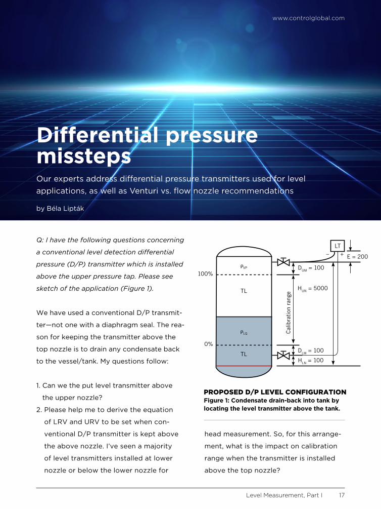
Q: I have the following questions concerning
a conventional level detection differential
pressure (D/P) transmitter which is installed
above the upper pressure tap. Please see
sketch of the application (Figure 1).
We have used a conventional D/P transmit-
ter—not one with a diaphragm seal . The rea-
son for keeping the transmitter above the
top nozzle is to drain any condensate back
to the vessel/tank . My questions follow:
1 . Can we the put level transmitter above
the upper nozzle?
2 . Please help me to derive the equation
of LRV and URV to be set when con-
ventional D/P transmitter is kept above
the above nozzle . I’ve seen a majority
of level transmitters installed at lower
nozzle or below the lower nozzle for
head measurement . So, for this arrange-
ment, what is the impact on calibration
range when the transmitter is installed
above the top nozzle?
www.controlglobal.com
Level Measurement, Part I 17
Differential pressure misstepsOur experts address differential pressure transmitters used for level applications, as well as Venturi vs . flow nozzle recommendations
by Béla Lipták
LT
0%
100%
DLM = 100
HLN = 100
HUN = 5000
DUM = 100
E = 200
Cal
ibra
tion
rang
e
– +
TL
TL
PROPOSED D/P LEVEL CONFIGURATIONFigure 1: Condensate drain-back into tank by locating the level transmitter above the tank.

www.controlglobal.com
Level Measurement, Part I 18
3 . Is this arrangement, which does not in-
clude diaphragm seal, seal pot or purging,
allowed per international standards such
as API best practices?
4 . When there is 10% of liquid filled up, how
will liquid create head on the transmitter
(high pressure side)?
5 . How do we ensure that liquid head will
be acting on the high-pressure leg all the
time (without any vapor pocket) when
the actual level inside the tank is 10-15%?
6 . How do we ensure that density of vapor
will be the same on impulse tubing (par-
ticularly on low pressure side), so that
the chance of measurement error will be
minimized?
Jatin Katrodiya
jatinkatrodiya@yahoo .com
A1: The operating pressure creates serious
problems . It’s my experience that every-
thing leaks; the only question is how much .
It would be very difficult to keep the high-
pressure sensing line filled only with gas .
Your scheme as shown will most likely fail
to work even at startup . If the pressure was
low enough, I would suggest a purge on
both connections . That will require a com-
pressed gas source . I would prefer to use
remote chemical seals in this service .
Cullen langford
cullenl@aol .com
A2: If for some reason you don’t want to use
chemical seals or purge both connections,
but you do want the condensate to drain
back into the tank, you can follow Figure 2
and reverse the output of the transmitter .
Naturally, you have to correct for the den-
sity difference between that of the ambient
temperature condensate and the density of
liquid in the tank .
Béla Lipták
liptakbela@aol .com
A3: You certainly have a non-conforming in-
stallation . Most installations locate the lower
leg below the tank, and use diaphragm seals
on both legs . Unless the “high pressure”
(HP) leg is a filled tube with diaphragm
seals on both sides, I don’t see how the high
pressure from liquid level and vapor pres-
sure can get to the level transmitter .
If your high pressure leg is diaphragm
sealed and filled with an inert transfer fluid,
it will appear to the level transmitter as
the head (pressure) of the transfer fluid
plus the head of the liquid in the tank plus
the pressure head of the vapor space . The
Boiling fluid
Slope
Condensingchamber
LT
LP
HP
ALTERATE D/P LEVEL SOLUTIONFigure 2: Seal-less D/P level measurement solution as often applied to boiling fluids.

www.controlglobal.com
Level Measurement, Part I 19
low pressure (LP) side will see only the
pressure of the vapor space . When you
subtract the HP pressure from the LP (the
reading of the transmitter) you will have
the liquid level in the tank plus the head of
the HP leg . Since the HP leg is a constant,
it can be removed by setting the zero point
of the level transmitter . Now you should be
able to do your math .
Dick Caro
ISA Life Fellow
RCaro@CMC .us
VENTURI VS. FLOW NOZZLE?Q. Working as an instrument engineer in
the oil and gas industry, I’ve specified a
flow measuring device as an orifice meter,
but while sizing with maximum beta ratio,
the resulting permanent pressure loss is
higher than what the process department
allowed as the maximum allowable pres-
sure drop. Hence, it’s understood that
orifice will not be suitable for this mea-
surement purpose, and I’m considering
some alternatives for the process condi-
tions and line size. As an alternative to the
orifice, in order to meet the process maxi-
mum allowable pressure drop, we decided
to go with either a Venturi or flow nozzle
primary element.
Now, I don’t know which to chose . Can you
suggest the factors or considerations in
which a Venturi meter is preferred to a flow
nozzle or vice versa? What are the basic
considerations that have to be taken into
account for selecting one or the other, and
which is preferred and why so?
M . Ulangatham
Instrument Engineer
ulaganathan .inst@gmail .com
A1: In general, you want to use Venturi mea-
surement when the range is small, say less
than 100 in . H2O, and nozzles when you have
a larger flow range . Most Venturi meters
you’ll calibrate for 0-10 or 0-25 in . H2O . Flow
nozzles work basically as a restriction orifice
(RO), so use the same basic principle .
Alex (Alejandro) Varga
vargaalex@yahoo .com
A2: The flow nozzle is a prefered choice for
steam flow measurement .
Debasis Guha
debasis_guha71@yahoo .com
A3: This is a common question, so I’ll give
you a more detailed answer .
The meter coefficient of a typical orifice is
about 0 .62, while that of a Venturi or flow
nozzle is almost one (0 .99) . Therefore, at
the same P and the same ß ratio (diam-
eter of restriction divided by the pipe inside
diameter), these meters pass about 40%
more flow than an orifice .
The big difference between them is in their
cost and pressure recovery . The cost of the
Venturi is higher, say about $6,000 for an
8 in . cast iron one, while an 8 in . aluminum
www.controlglobal.com
Level Measurement, Part I 20
nozzle is about $1,200 . At a beta ratio of 0 .5,
a standard Venturi recovers about 85% of its
differential, while at the same beta ratio, an
ASME flow nozzle only recovers about 35%
of its differential . Consequently, because of
the high pressure recovery of the Venturi, its
operating costs are much lower . As a result,
the savings in pumping costs can quickly
compensate for the initial price difference .
Among the two, the Venturi is more accu-
rate, about 1% full scale (FS), while the flow
nozzle is about 2% FS . The rangeability of
both is about 4:1 . The straight run require-
ment of nozzles are longer (10-30 diam-
eters) than Venturis (5-20 diameters), but
not that much . Flow nozzles are available
in a largerr range of beta-ratio (0 .3-0 .7) .
And as far as installation goes, flow nozzles
should be installed downflow when used on
wet gases, wet steam or liquids with sus-
pended solids, but neither meter should be
used on slurries or dirty fluids .
With Venturi meters, cavitation can be a
problem when the downstream pressure of
a liquid drops below the fluid’s vapor pres-
sure . Bubbles form, and cavitation can de-
stroy the throat of the meter . The bottom
line is: because your process people are
concerned about pressure loss, a Venturi
should be used .
Béla Lipták
liptakbela @aol .com

Headlinedeckbyline
Q: Why is it that the shaft of some open/close actuators for rotary valves are off-center?
Enclosed you can find an image of open/close butterfly valve (non-control valve) and its
actuator. The shaft of the actuator is not in the center. Why? I think this is a rack-and-pinion
actuator, and I couldn’t find out why its shaft is out of center of the actuator.
Ali Rahimi
a .rahimi .aut@gmail .com
A1: When the size of a rotary valve (ball, plug) exceeds about 3-in ., it tends to become bulky,
hard to handle and—if manufactured of a sophisticated heat and/or corrosion-resistant mate-
rial—can also become quite expensive . So, for larger valves, we consider using butterfly de-
signs that can go up to 144 in . in diameter . Butterfly valve advantages include compact size,
light weight, quick action, low pressure drop, high pressure recovery and tight closure . Dis-
advantages include poor throttling performance at high pressure drop, disc movement that’s
influenced by turbulence, and a potential for choked flow and cavitation . The disc of this valve
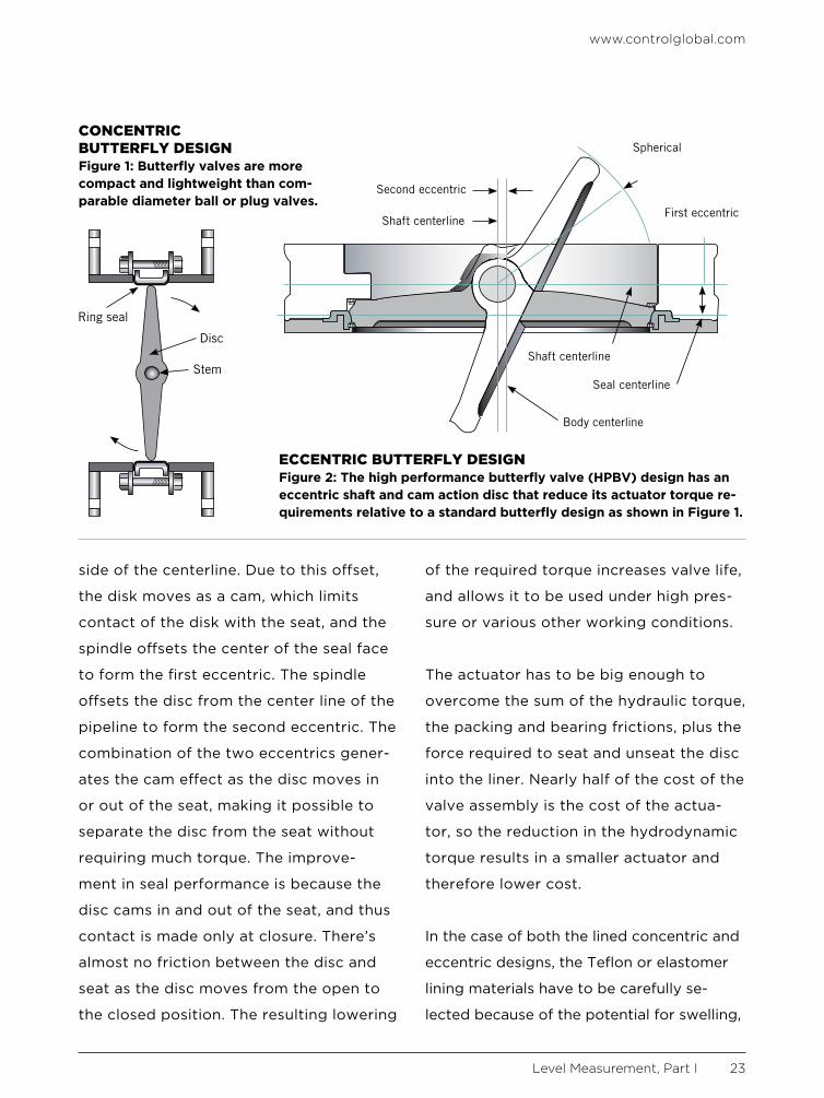
can be concentric (Figure 1) or use an eccentric, cammed design (Figure 2) .
You, Ali, are referring to the second version, which is also referred to as a high-perfor-
mance butterfly valve (HPBV) . The HPBV design has a cammed disc and a separable
seat ring clamped into the body . It has two offsets: one is a shift in the position of the
shaft behind the valve disk, and the second is a shift in the shaft position slightly to one
www.controlglobal.com
Level Measurement, Part I 22
Of eccentric valves and errant dp cellsOur experts explain why eccentric butterfly valves are also high performance, and why a proposed level measurement solution is likely doomed from the start
by Béla Lipták
www.controlglobal.com
Level Measurement, Part I 23
side of the centerline . Due to this offset,
the disk moves as a cam, which limits
contact of the disk with the seat, and the
spindle offsets the center of the seal face
to form the first eccentric . The spindle
offsets the disc from the center line of the
pipeline to form the second eccentric . The
combination of the two eccentrics gener-
ates the cam effect as the disc moves in
or out of the seat, making it possible to
separate the disc from the seat without
requiring much torque . The improve-
ment in seal performance is because the
disc cams in and out of the seat, and thus
contact is made only at closure . There’s
almost no friction between the disc and
seat as the disc moves from the open to
the closed position . The resulting lowering
of the required torque increases valve life,
and allows it to be used under high pres-
sure or various other working conditions .
The actuator has to be big enough to
overcome the sum of the hydraulic torque,
the packing and bearing frictions, plus the
force required to seat and unseat the disc
into the liner . Nearly half of the cost of the
valve assembly is the cost of the actua-
tor, so the reduction in the hydrodynamic
torque results in a smaller actuator and
therefore lower cost .
In the case of both the lined concentric and
eccentric designs, the Teflon or elastomer
lining materials have to be carefully se-
lected because of the potential for swelling,
CONCENTRIC BUTTERFLY DESIGNFigure 1: Butterfly valves are more compact and lightweight than com-parable diameter ball or plug valves.
Ring seal
Disc
Stem
ECCENTRIC BUTTERFLY DESIGNFigure 2: The high performance butterfly valve (HPBV) design has an eccentric shaft and cam action disc that reduce its actuator torque re-quirements relative to a standard butterfly design as shown in Figure 1.
Second eccentric
Shaft centerline
Spherical
First eccentric
Shaft centerline
Seal centerline
Body centerline
www.controlglobal.com
Level Measurement, Part I 24
softening or cracking . These
seat designs are usually
classified as bubble-tight
(ANSI Class VI) .
Béla Lipták
liptakbela @aol .com
A2: I believe that on closer
inspection you’ll see that
the shaft is designed to turn
easily for much of its stroke,
then pushes the disk into
the seat just as it turns into
closure .
Cullen Langford
cullenl@aol .com
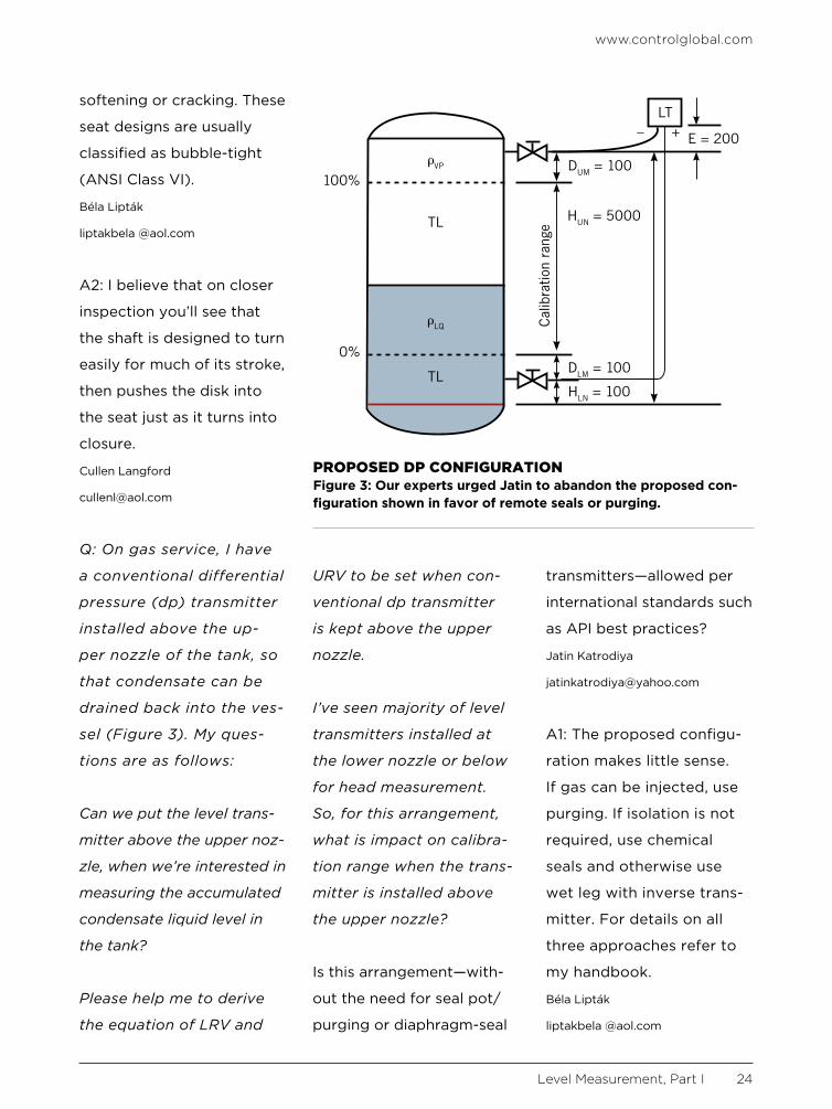
Q: On gas service, I have
a conventional differential
pressure (dp) transmitter
installed above the up-
per nozzle of the tank, so
that condensate can be
drained back into the ves-
sel (Figure 3). My ques-
tions are as follows:
Can we put the level trans-
mitter above the upper noz-
zle, when we’re interested in
measuring the accumulated
condensate liquid level in
the tank?
Please help me to derive
the equation of LRV and
URV to be set when con-
ventional dp transmitter
is kept above the upper
nozzle.
I’ve seen majority of level
transmitters installed at
the lower nozzle or below
for head measurement.
So, for this arrangement,
what is impact on calibra-
tion range when the trans-
mitter is installed above
the upper nozzle?
Is this arrangement—with-
out the need for seal pot/
purging or diaphragm-seal
transmitters—allowed per
international standards such
as API best practices?
Jatin Katrodiya
jatinkatrodiya@yahoo .com
A1: The proposed configu-
ration makes little sense .
If gas can be injected, use
purging . If isolation is not
required, use chemical
seals and otherwise use
wet leg with inverse trans-
mitter . For details on all
three approaches refer to
my handbook .
Béla Lipták
liptakbela @aol .com
LT
0%
100%
DLM = 100
HLN = 100
HUN = 5000
DUM = 100
E = 200
Cal
ibra
tion
rang
e
– +
TL
TL
PROPOSED DP CONFIGURATIONFigure 3: Our experts urged Jatin to abandon the proposed con-figuration shown in favor of remote seals or purging.

www.controlglobal.com
Level Measurement, Part I 25
A2: The operating pressure creates serious
problems . It’s my experience that every-
thing leaks, the only question is how much?
It would be very difficult to keep the high-
pressure sensing line filled only with gas .
Your scheme as shown will most likely fail
to work even at startup . If the pressure is
low enough, then I would suggest using a
purge on both connections . That will require
a compressed gas source . I would prefer to
use remote chemical seals in this service .
Cullen Langford
cullenl@aol .com
A3: You certainly have a non-conforming in-
stallation . Most installations locate the level
transmitter below the tank, and use dia-
phragm seals on both legs . Unless the “high
pressure” leg is a filled tube with diaphragm
seals on both sides, I don’t see how the high
pressure from liquid level + vapor pressure
can get to the transmitter .
If your high-pressure leg is diaphragm sealed
and filled with an inert transfer fluid, it will
appear to the transmitter as the head (pres-
sure) of the transfer fluid + the head of the
liquid in the tank + the pressure head of the
vapor space . The low-pressure (LP) side will
see only the pressure of the vapor space .
When you subtract the HP pressure from the
LP (the reading of the LT), you’ll have the
liquid level in the tank + the head of the HP
leg . Since the HP leg is a constant, it can be
removed by setting the zero point of the LT .
Now you should be able to do your math .
Richard H . Caro
CEO, CMC Associates
ISA Life Fellow
RCaro@CMC .us (buy my books at the ISA Bookstore)