LEVEL BEST Service Guide - System Lookup - Power Gear
20
THE MclNTOSH MC 2155 SOLID STATE STEREO POWER AMPLIFIER Reading Time: 31 Minutes Price $2.00
Transcript of LEVEL BEST Service Guide - System Lookup - Power Gear

THE MclNTOSH MC 2155 SOLID STATE STEREOPOWER AMPLIFIER
Reading Time: 31 Minutes Price $2.00
VARIOUS REGULATORY AGENCIES REQUIRE THAT WE BRING THE FOLLOWINGINFORMATION TO YOUR ATTENTION. PLEASE READ IT CAREFULLY.
WARNING: TO PREVENT FIRE OR SHOCKHAZARD, DO NOT EXPOSE THIS UNIT TORAIN OR MOISTURE.
The Mclntosh you have purchased is a Model
MC 2155. It has a serial number located on the rear panel
of the chassis. Record that serial number here:
Serial Number
The model, serial number and purchase date are im-
portant to you for any future service. Record the pur-
chase date here:
Purchase date
Upon application, Mclntosh Laboratory provides a
Three-Year Service Contract. Your Mclntosh authorized
Service Agency can expedite repairs when you provide
the Service Contract with the instrument for repair. To
assist, record your Service Contract number here:
Service Contract Number
Your MC 2155 Stereo Power Amplifierwill give you many years of pleasantand satisfactory performance. If youhave any questions, please contact:
CUSTOMER SERVICEMclntosh Laboratory Inc.2 Chambers StreetBinghamton, New York 13903-9990Phone: 607-723-3512
Take Advantage of 3 yearsof Contract Service...Fill in the Application NOW.
ContentsSERVICE 1
INSTALLATION 2HOW TO CONNECT 4
FRONT PANEL INFORMATION 9REAR PANEL INFORMATION 11
PERFORMANCE LIMITS AND RATINGS 12PERFORMANCE CHARTS 13
TECHNICAL DESCRIPTION 15BLOCK DIAGRAM 17
MclNTOSH THREE YEAR SERVICE CONTRACTAn application for A THREE YEAR SERVICE CONTRACT is included with this manual.
The terms of the contract are:1. Mclntosh will provide all parts, materials
and labor needed to return the measuredperformance of the instrument to theoriginal performance limits. The SER-VICE CONTRACT does not cover anyshipping costs to and from the authoriz-ed service agency or the factory.
2. Any Mclntosh authorized service agencywill repair Mclntosh instruments at nor-mal service rates. To receive serviceunder the terms of the SERVICE CON-TRACT, the SERVICE CONTRACT CER-TIFICATE must be presented when theinstrument is taken to the service agency.
3. Always have service done by aMclntosh authorized service agency. Ifthe instrument is modified or damagedas a result of unauthorized repair, theSERVICE CONTRACT will be cancelled.Damage by improper use or mishan-dling is not covered by the SERVICECONTRACT.
4. The SERVICE CONTRACT is issued toyou as the original purchaser. To pro-tect you from misrepresentation, this
contract cannot be transferred to a se-cond owner.
5. To receive the SERVICE CONTRACT,your purchase must be made from aMclntosh franchised dealer.
6. Your completely filled in application forthe SERVICE CONTRACT must be post-marked within 30 days of the date ofpurchase of the instrument.
7. To receive the SERVICE CONTRACT, allinformation on the application must befilled in. The SERVICE CONTRACT willbe issued when the completely filled inapplication is received by MclntoshLaboratory Incorporated in Binghamton,New York.
8. Units in operation outside the UnitedStates and Canada are not covered bythe Mclntosh Factory Service Contract,irrespective of the place of purchase.Nor are units acquired outside theU.S.A. and Canada, the purchasers ofwhich should consult with their dealerto ascertain what, if any, service con-tract or warranty may be available locally.
Copyright 1981 © by Mclntosh Laboratory Inc. 1

tion the instrument can be mounted in any position.The recommended minimum space for installationis 15 inches (38.1 cm)deep, 17 inches (43.2 cm) wide,and 6 inches (15.2 cm) high.
To install the instrument in a Mclntosh cabinet,follow the instructions that are enclosed with thecabinet for any other type of installation, follow
1. Open the carton and remove the PANLOC brack-ets, hardware package and mounting template. Re-move the MC 2155 from the plastic bag and place itupside down on the shipping pallet then unscrewthe four plastic feet from the bottom of the chassis.
these instructions:
2. Mark the cabinet panelPlace the mounting template in the position on thecabinet pane! where the instrument is to be install-ed, and tape it in place. The broken lines that repre-sent the outline of the rectangular cutout also repres-sent the outside dimensions of the chassis. Makesure these lines clear shelves, partitions or anyequipment. With the template in place, first mark thesix A and B holes and the four small holes thatlocate the corners of the cutout. Then, join the fourcorner markings with pencil lines using the edge ofthe template as a straight edge.
3. Drill HolesUse a drill with a 3/16 inch bit held perpendicular to thepanel and drill the six A and B holes. Then, using a drillbit slightly wider than the tip of your saw blade, drillone hole at each of two diagonally opposite corners.The holes should barely touch the inside edge of thepenciled outline. Before taking the next step, makesure that the six A and 8 holes have been drilled.
4. Saw the Panel CutoutSaw carefully on the inside of the penciled lines.First make the two long cuts and then the two shortcuts. After the rectangular opening has been cut out.use a file to square the corners and smooth anyirregularities in the cut edges.
The PANLOC system of installing equipment con-veniently and securely is a direct result of Mclntoshresearch. By depressing the two PANLOC buttonson the front panel, the instrument either can be lock-ed firmly in place or it can be unlocked so that thechassis can slide forward, giving you easy access tothe top and rear panels.
The trouble-free life of an electronic instrument isgreatly extended by providing sufficient ventilationto prevent the build-up of high internal temperaturesthat cause deterioration. Allow enough clearance sothat cool air can enter at the bottom of the cabinetand be vented from the top. With adequate ventila-
2
Starting at the right-hand side of the panel, inserta screw of proper length into the center hole in thepanel. marked B on the template. On the back of thepanel, align a mounting strip with the holes in thepanel and tighten the screw until the screwhead ispulled slightly into the wood.
Repeat this procedure to attach the mountingstrip to the left side of the panel.
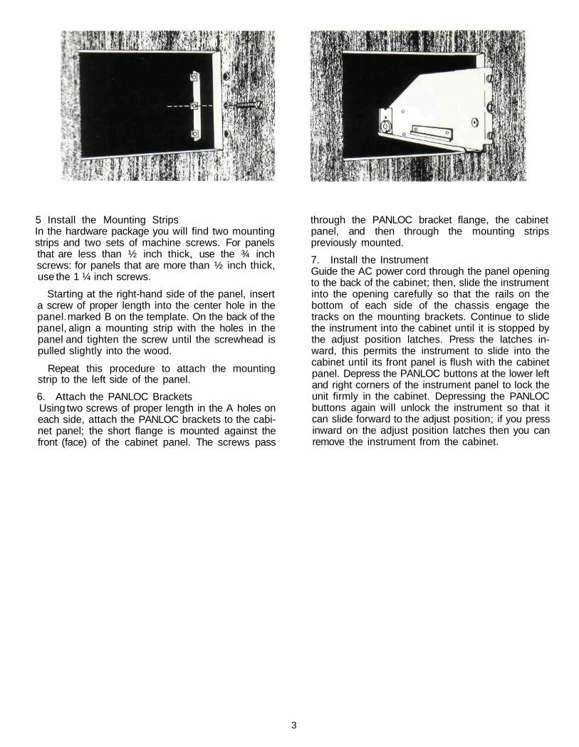
6. Attach the PANLOC BracketsUsing two screws of proper length in the A holes oneach side, attach the PANLOC brackets to the cabi-net panel; the short flange is mounted against thefront (face) of the cabinet panel. The screws pass
through the PANLOC bracket flange, the cabinetpanel, and then through the mounting stripspreviously mounted.
7. Install the InstrumentGuide the AC power cord through the panel openingto the back of the cabinet; then, slide the instrumentinto the opening carefully so that the rails on thebottom of each side of the chassis engage thetracks on the mounting brackets. Continue to slidethe instrument into the cabinet until it is stopped bythe adjust position latches. Press the latches in-ward, this permits the instrument to slide into thecabinet until its front panel is flush with the cabinetpanel. Depress the PANLOC buttons at the lower leftand right corners of the instrument panel to lock theunit firmly in the cabinet. Depressing the PANLOCbuttons again will unlock the instrument so that itcan slide forward to the adjust position; if you pressinward on the adjust position latches then you canremove the instrument from the cabinet.
5 Install the Mounting StripsIn the hardware package you will find two mountingstrips and two sets of machine screws. For panelsthat are less than ½ inch thick, use the ¾ inchscrews: for panels that are more than ½ inch thick,use the 1 ¼ inch screws.
3

How to Connect
INPUTSTEREO OPERATION
Use shielded cables to connect the signal fromthe preamplifier or signal source to the poweramplifier. To minimize the possibilty of hum theshielded cables should be run parallel to each otheror loosely twisted together. Locate the cables awayfrom speaker leads and AC power cords. All connec-tions are made on the back panel of the MC 2155.
For stereo operation, the left output of thepreamplifier should be plugged into the Left inputjack of the power amplifier. The right output of thepreamplifier should be plugged into the Right(Mono) input jack of the power amplifier.
In stereo operation the MODE SWITCH must be inthe STEREO position.
MONOPHONIC OR SINGLE CHANNEL OPERATIONA shielded cable from the signal source is plug-
ged into the Right (Mono) input jack of the MC 2155only. The MODE SWITCH on the back panel of theamplifier must be placed in one of the MONO posi-tions. In the MONO positions the output of the rightchannel input amplifier is fed to both left and rightpower amplifiers. The Left INPUT is disconnected.Only the signal fed into the Right (MONO) input willbe amplified.
Be certain that the MC 2155 is never operated inthe stereo mode with the outputs connected formonophonic operation. Should the MODE SWITCHbe left in the STEREO position and the outputs re-main strapped for a mono parallel load, one channelwill attempt to drive the other which causes high cir-culating currents and overheating.
OUTPUTBe certain the loudspeakers connected to the MC
2155 are capable of handling the power output of theamplifier.
Selection of the proper gauge wire to connect theloudspeakers preserves the quality of sound repro-
duction for which the loudspeakers have been de-signed. If undersize wire is used, resistance is addedto the amplifier/loudspeaker combination whichadversely affects the performance. Added resis-tance causes depreciation of damping characteris-tics, modification of frequency response and reduc-tion in power output.
Use lamp cord or wire with similar insulation toconnect the speakers to the amplifier. In all cases,the leads to and from the speaker should be twinconductor or twisted together. When using 8 ohmspeakers and for the normally short distances ofunder 30 feet between the amplifier and speaker, #18 wire or larger can be used. For distances over 30feet use larger diameter wire. Select the correct sizewire from the chart below. It is recommended thatthe DC resistance of the speaker leads be less than5% of the speaker impedance. Resistance of theleads should be computed for the length of wire bothto and from the speaker or speakers.
For multiple speaker operation, run separateleads from the amplifier to the speakers.
Wire
Gauge1816141210
MAXIMUM WIRE LENGTHSFor 4 Ohm Load
Feet15254060
100
Meters4.577.62
12.1918.2930.48
For 8 Ohm Load
Feet305080
120200
Meters9.14
15.2424.3836.5860.96
Wire lengths above represent the wire resistanceequal to 5% of the speaker impedance.
STEREO OPERATION
Check the impedance of the speaker which isusually identified on the speaker itself or in theowner's manual. Connect a lead from the commonterminal of the left speaker to the amplifier LEFTOUTPUT terminal strip COMmon screw. Connect
4
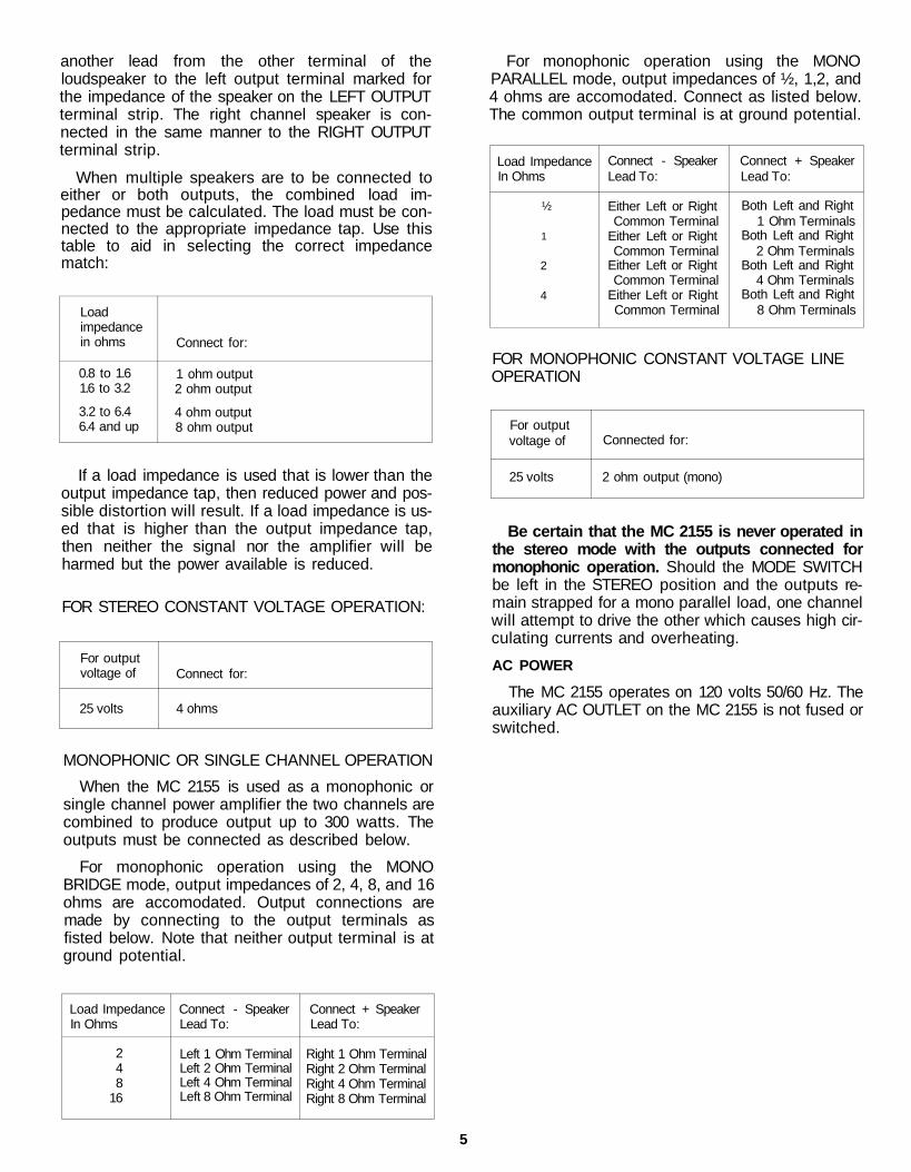
another lead from the other terminal of theloudspeaker to the left output terminal marked forthe impedance of the speaker on the LEFT OUTPUTterminal strip. The right channel speaker is con-nected in the same manner to the RIGHT OUTPUTterminal strip.
When multiple speakers are to be connected toeither or both outputs, the combined load im-pedance must be calculated. The load must be con-nected to the appropriate impedance tap. Use thistable to aid in selecting the correct impedancematch:
Loadimpedancein ohms
0.8 to 1.61.6 to 3.2
3.2 to 6.46.4 and up
Connect for:
1 ohm output2 ohm output
4 ohm output8 ohm output
If a load impedance is used that is lower than theoutput impedance tap, then reduced power and pos-sible distortion will result. If a load impedance is us-ed that is higher than the output impedance tap,then neither the signal nor the amplifier will beharmed but the power available is reduced.
FOR STEREO CONSTANT VOLTAGE OPERATION:
For outputvoltage of
25 volts
Connect for:
4 ohms
MONOPHONIC OR SINGLE CHANNEL OPERATION
When the MC 2155 is used as a monophonic orsingle channel power amplifier the two channels arecombined to produce output up to 300 watts. Theoutputs must be connected as described below.
For monophonic operation using the MONOBRIDGE mode, output impedances of 2, 4, 8, and 16ohms are accomodated. Output connections aremade by connecting to the output terminals asfisted below. Note that neither output terminal is atground potential.
For monophonic operation using the MONOPARALLEL mode, output impedances of ½, 1,2, and4 ohms are accomodated. Connect as listed below.The common output terminal is at ground potential.
Load ImpedanceIn Ohms
½
1
2
4
Connect - SpeakerLead To:
Either Left or RightCommon Terminal
Either Left or RightCommon Terminal
Either Left or RightCommon Terminal
Either Left or RightCommon Terminal
Connect + SpeakerLead To:
Both Left and Right1 Ohm Terminals
Both Left and Right2 Ohm Terminals
Both Left and Right4 Ohm Terminals
Both Left and Right8 Ohm Terminals
FOR MONOPHONIC CONSTANT VOLTAGE LINEOPERATION
For outputvoltage of
25 volts
Connected for:
2 ohm output (mono)
Be certain that the MC 2155 is never operated inthe stereo mode with the outputs connected formonophonic operation. Should the MODE SWITCHbe left in the STEREO position and the outputs re-main strapped for a mono parallel load, one channelwill attempt to drive the other which causes high cir-culating currents and overheating.
AC POWER
The MC 2155 operates on 120 volts 50/60 Hz. Theauxiliary AC OUTLET on the MC 2155 is not fused orswitched.
Load ImpedanceIn Ohms
248
16
Connect - SpeakerLead To:
Left 1 Ohm TerminalLeft 2 Ohm TerminalLeft 4 Ohm TerminalLeft 8 Ohm Terminal
Connect + SpeakerLead To:
Right 1 Ohm TerminalRight 2 Ohm TerminalRight 4 Ohm TerminalRight 8 Ohm Terminal
5
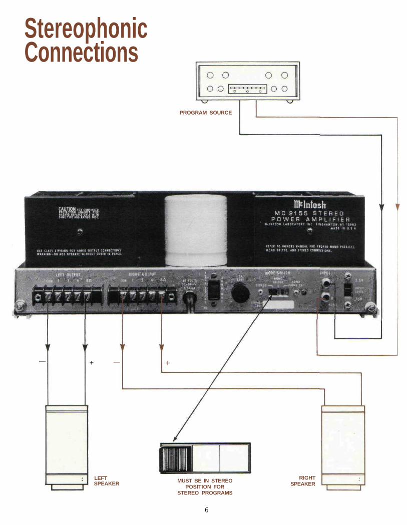
StereophonicConnections
PROGRAM SOURCE
MUST BE IN STEREOPOSITION FOR
STEREO PROGRAMS
6
RIGHTSPEAKER
LEFTSPEAKER
+ +——

Mono-BridgeConnections
PROGRAM SOURCE
(CONNECTIONS FOR8 OHM SPEAKER
ILLUSTRATED)
CONNECTIONS SHOWN FOR MONOWHEN MODE SWITCH
IS IN THE MONO-BRIDGE POSITIONSPEAKER
7
— +
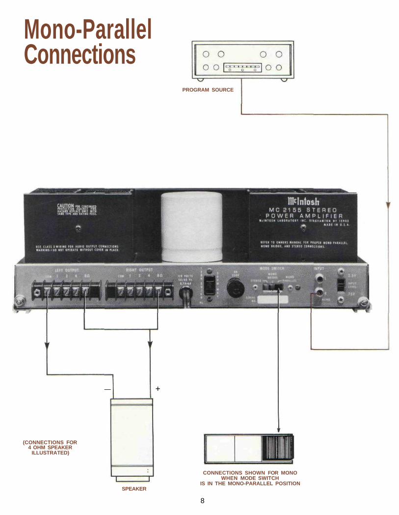
Mono-ParallelConnections
(CONNECTIONS FOR4 OHM SPEAKER
ILLUSTRATED)
SPEAKER
CONNECTIONS SHOWN FOR MONOWHEN MODE SWITCH
IS IN THE MONO-PARALLEL POSITION
PROGRAM SOURCE
+—
8
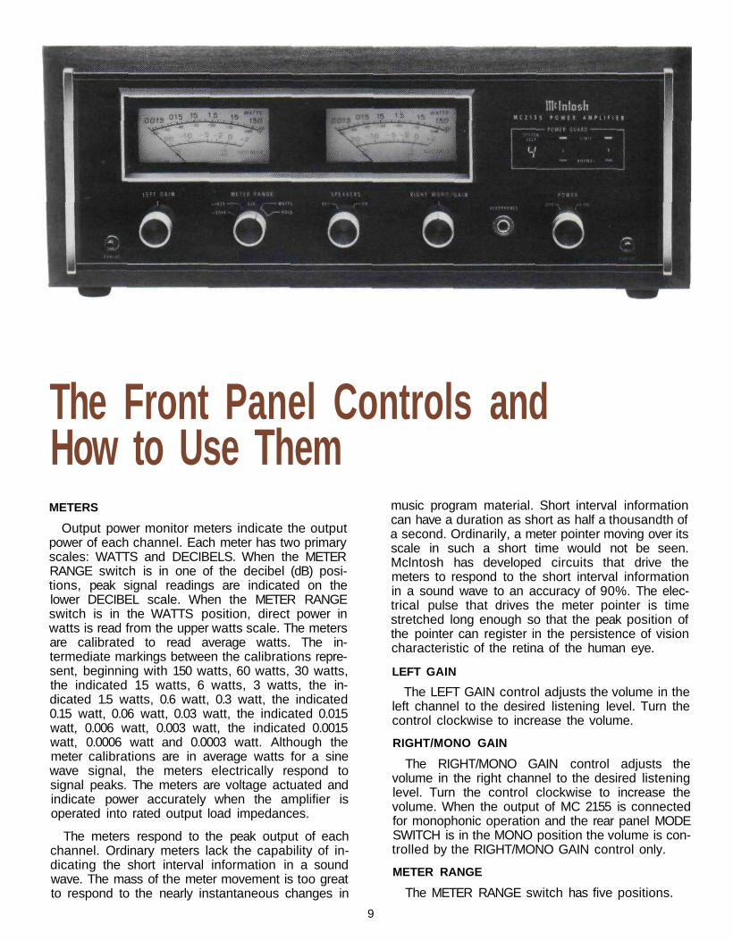
The Front Panel Controls andHow to Use ThemMETERS
Output power monitor meters indicate the outputpower of each channel. Each meter has two primaryscales: WATTS and DECIBELS. When the METERRANGE switch is in one of the decibel (dB) posi-tions, peak signal readings are indicated on thelower DECIBEL scale. When the METER RANGEswitch is in the WATTS position, direct power inwatts is read from the upper watts scale. The metersare calibrated to read average watts. The in-termediate markings between the calibrations repre-sent, beginning with 150 watts, 60 watts, 30 watts,the indicated 15 watts, 6 watts, 3 watts, the in-dicated 1.5 watts, 0.6 watt, 0.3 watt, the indicated0.15 watt, 0.06 watt, 0.03 watt, the indicated 0.015watt, 0.006 watt, 0.003 watt, the indicated 0.0015watt, 0.0006 watt and 0.0003 watt. Although themeter calibrations are in average watts for a sinewave signal, the meters electrically respond tosignal peaks. The meters are voltage actuated andindicate power accurately when the amplifier isoperated into rated output load impedances.
The meters respond to the peak output of eachchannel. Ordinary meters lack the capability of in-dicating the short interval information in a soundwave. The mass of the meter movement is too greatto respond to the nearly instantaneous changes in
music program material. Short interval informationcan have a duration as short as half a thousandth ofa second. Ordinarily, a meter pointer moving over itsscale in such a short time would not be seen.Mclntosh has developed circuits that drive themeters to respond to the short interval informationin a sound wave to an accuracy of 90%. The elec-trical pulse that drives the meter pointer is timestretched long enough so that the peak position ofthe pointer can register in the persistence of visioncharacteristic of the retina of the human eye.
LEFT GAIN
The LEFT GAIN control adjusts the volume in theleft channel to the desired listening level. Turn thecontrol clockwise to increase the volume.
RIGHT/MONO GAIN
The RIGHT/MONO GAIN control adjusts thevolume in the right channel to the desired listeninglevel. Turn the control clockwise to increase thevolume. When the output of MC 2155 is connectedfor monophonic operation and the rear panel MODESWITCH is in the MONO position the volume is con-trolled by the RIGHT/MONO GAIN control only.
METER RANGE
The METER RANGE switch has five positions.
9

WATTS
In the WATTS position the meter's primary calibra-tion is from .0015 watts (one and a half milliwatts),up to 150 watts, the rated power output of the MC2155. The meter is calibrated for 300 watts at theright hand end of the meter scale. While the MC2155cannot reach this power level continuously, it ispossible for short interval peaks to exceed, con-siderably, the 150 watt continuous rating.
HOLD
In the HOLD position, the meter indicates WATTSand locks to the highest power peak in a sequenceof peaks. The meter will be driven to maximumpower and electronically held there until a higherpeak passes through the amplifier. If no furtherpeaks are reached the meter needle will very slowlyreturn to its rest position (decay rate: 6 dB perminute).
DECIBELS
In the other three positions of the METER RANGEswitch the meters will indicate the output of eachchannel in DECIBELS relative to 150 watts or anyother chosen reference.
0dB In this position of the switch, if theamplifier delivers 150 average watts, themeter indicates 0 dB; at 75 average wattsthe meter indicates -3 dB. If the amplifieris overdriven to +2 dB the indicated out-put would be 238 watts.
-10dB In this position of the switch, if theamplifier delivers 15 average watts, themeter indicates 0 dB; at 7.5 average wattsthe meter indicates -3 dB.
-20dB In this position of the switch, if theamplifier delivers 1.5 average watts, themeter indicates 0 dB; at .75 average wattsthe meter indicates -3 dB.
HEADPHONES
The output of the front panel HEADPHONE jackhas been designed to feed low impedance dynamicstereo headphones.
The HEADPHONE output is not affected by theSPEAKER switch.
SPEAKERS
OFF: The loudspeakers are turned off when theSPEAKER switch is in the OFF position. You can lis-ten to headphones in private.
THE SPEAKER SWITCH MUST BE IN THE "ON" POSI-TION TO HEAR MUSIC FROM THE LOUDSPEAKERS.
ON: Music will be heard through the loudspeakers.Use this as the normal listening position.
POWER
The power switch turns the MC 2155 ON or OFF.The switch does not control the power outlet on theback panel. If you wish to control the AC power froma preamplifier control center leave the switch in theON position. Be sure the AC cord of the MC 2155 isplugged into the controlled outlets on the rear of thepreamplifier control center.
OFF: In the OFF position the AC power to theamplifier is turned off.
POWER GUARD
POWER GUARD assures that the MC 2155 cannotbe overdriven, thus amplifier output clipping iseliminated. Clipping is caused when an amplifier isasked to produce more power output than it candeliver with low distortion. Amplifiers are capable ofdelivering large quantities of highly distorted powerwhen they are driven to clipping. The extra energycontent of the clipped signal will damage mostspeakers. Mclntosh's Power Guard circuit protectsyour speakers from this kind of damage. The MC2155 has a built in "waveform comparator" thatcompares the wave shape of the output signal to theinput signal. If the disparity between the twosignals, due to overdrive, exceeds 0.5% (equivalentto 0.5% total harmonic distortion) a red LIMITindicator illuminates. With any further increase indistortion the Power Guard circuit operates tolimit the amplifier input dynamically so that theamplifier cannot be overdriven. Power Guardeliminates amplifier output clipping. As long as the
amplifier operates withoutoverload the NORMAL in-dicator illuminates.
NEW AUTOMATIC TESTSYSTEMThe MC 2155 contains anew automatic test circuit.When AC line power is ap-
plied, an LED digit illuminates to indicate which testis being performed. Starting with the numeral 7, itmakes the required measurement and verifies if it iswithin tolerance by lighting the "normal" PowerGuard green lights. It then counts down to six, per-forms and verifies the next test, then five, four, three,etc. until it reaches " 1 " and then the speakers turnon. A "beep" tone is heard each time a test is per-formed. If a circuit should fail, the red "limit" lightswill come on and the sequence will stop at thatpoint. Speaker turn on will not occur until the faulthas been corrected; thereby protecting your systemfrom any further damage.
There are two user controls associated with theauto test circuit. They are located on the amplifiertop panel. Two switches control the speed of thecountdown (SLOW or FAST) and the presence of thebeep tone (ON-OFF).
10
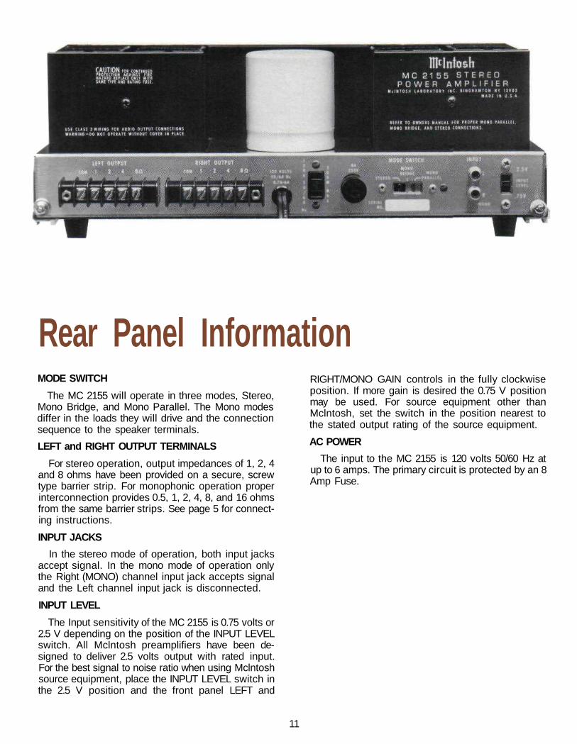
Rear Panel InformationMODE SWITCH
The MC 2155 will operate in three modes, Stereo,Mono Bridge, and Mono Parallel. The Mono modesdiffer in the loads they will drive and the connectionsequence to the speaker terminals.
LEFT and RIGHT OUTPUT TERMINALS
For stereo operation, output impedances of 1, 2, 4and 8 ohms have been provided on a secure, screwtype barrier strip. For monophonic operation properinterconnection provides 0.5, 1, 2, 4, 8, and 16 ohmsfrom the same barrier strips. See page 5 for connect-ing instructions.
INPUT JACKS
In the stereo mode of operation, both input jacksaccept signal. In the mono mode of operation onlythe Right (MONO) channel input jack accepts signaland the Left channel input jack is disconnected.
INPUT LEVEL
The Input sensitivity of the MC 2155 is 0.75 volts or2.5 V depending on the position of the INPUT LEVELswitch. All Mclntosh preamplifiers have been de-signed to deliver 2.5 volts output with rated input.For the best signal to noise ratio when using Mclntoshsource equipment, place the INPUT LEVEL switch inthe 2.5 V position and the front panel LEFT and
RIGHT/MONO GAIN controls in the fully clockwiseposition. If more gain is desired the 0.75 V positionmay be used. For source equipment other thanMclntosh, set the switch in the position nearest tothe stated output rating of the source equipment.
AC POWER
The input to the MC 2155 is 120 volts 50/60 Hz atup to 6 amps. The primary circuit is protected by an 8Amp Fuse.
11
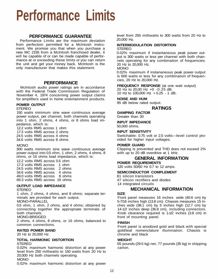
Performance LimitsPERFORMANCE GUARANTEE
Performance Limits are the maximum deviationfrom perfection permitted for a Mclntosh instru-ment. We promise you that when you purchase anew MC 2155 from a Mclntosh franchised dealer, itwill be capable of or can be made capable of perfor-mance at or exceeding these limits or you can returnthe unit and get your money back. Mclntosh is theonly manufacturer that makes this statement.
PERFORMANCEMclntosh audio power ratings are in accordance
with the Federal Trade Commission Regulation ofNovember 4, 1974 concerning power output claimsfor amplifiers used in home entertainment products.
POWER OUTPUTSTEREO150 watts minimum sine wave continuous averagepower output, per channel, both channels operatinginto 1 ohm, 2 ohms, 4 ohms, or 8 ohms load im-pedance, which is:12.2 volts RMS across 1 ohm17.3 volts RMS across 2 ohms24.5 volts RMS across 4 ohms34.6 volts RMS across 8 ohms
MONO300 watts minimum sine wave continuous averagepower output into 0.5 ohm, 1 ohm, 2 ohms, 4 ohms, 8ohms, or 16 ohms load impedance, which is:12.2 volts RMS across 0.5 ohm17.3 volts RMS across 1 ohm24.5 volts RMS across 2 ohms34.6 volts RMS across 4 ohms49.0 volts RMS across 8 ohms69.3 volts RMS across 16 ohms
OUTPUT LOAD IMPEDANCESTEREO1 ohm, 2 ohms, 4 ohms, and 8 ohms; separate ter-minals are provided for each output.MONO-PARALLEL0.5 ohm, 1 ohm, 2 ohms, and 4 ohms; obtained byconnecting together the appropriate terminals ofboth channels.MONO-BRIDGED2 ohms, 4 ohms, 8 ohms, or 16 ohms, balanced tocommon connections.
RATED POWER BAND20 Hz to 20,000 Hz
TOTAL HARMONIC DISTORTIONSTEREO0.02% maximum harmonic distortion at any powerlevel from 250 milliwatts to 150 watts from 20 Hz to20,000 Hz both channels operating.MONO0.02% maximum harmonic distortion at any power
level from 250 milliwatts to 300 watts from 20 Hz to20,000 Hz.
INTERMODULATION DISTORTIONSTEREO0.02% maximum if instantaneous peak power out-put is 300 watts or less per channel with both chan-nels operating for any combination of frequencies.20 Hz to 20,000 Hz.MONO0.02% maximum if instananeous peak power outputis 600 watts or less for any combination of frequen-cies, 20 Hz to 20,000 Hz.
FREQUENCY RESPONSE (at one watt output)20 Hz to 20,00 Hz +0 -0.25 dB.10 Hz to 100,000 Hz + 0.25 - 1 dB.
NOISE AND HUM95 dB below rated output.
RATINGSDAMPING FACTORGreater than 30
INPUT IMPEDANCE50,000 ohms.
INPUT SENSITIVITYSwitchable: 0.75 volt or 2.5 volts—level control pro-vided for higher input voltages.
POWER GUARDClipping is prevented and THD does not exceed 2%with up to 20 dB overdrive at 1 kHz.
GENERAL INFORMATIONPOWER REQUIREMENTS120 volts 50/60 Hz 0.7 to 12 amps.
SEMICONDUCTOR COMPLEMENT81 silicon transistors47 silicon rectifiers and diodes14 integrated circuits
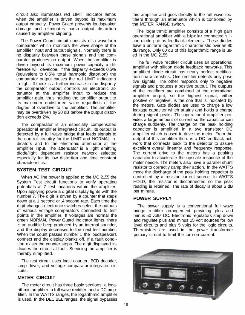
MECHANICAL INFORMATIONSIZEFront panel measures 16 inches wide (40.6 cm) by5-7/16 inches high (13.8 cm). Chassis measures 15 in-ches wide (38.1 cm) by 5 inches high (12.7 cm) by14-1/2 inches deep (36.8 cm), including connectors.Knob clearance required is 1-1/2 inches (3.8 cm) infront of mounting panel.
FINISHFront panel is anodized gold and black with specialgold/teal nomenclature illumination. Chassis ischrome and black
WEIGHT65 pounds (29.5 kg) net, 77 pounds (35 kg) in shippingcarton.
12
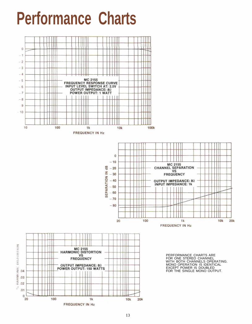
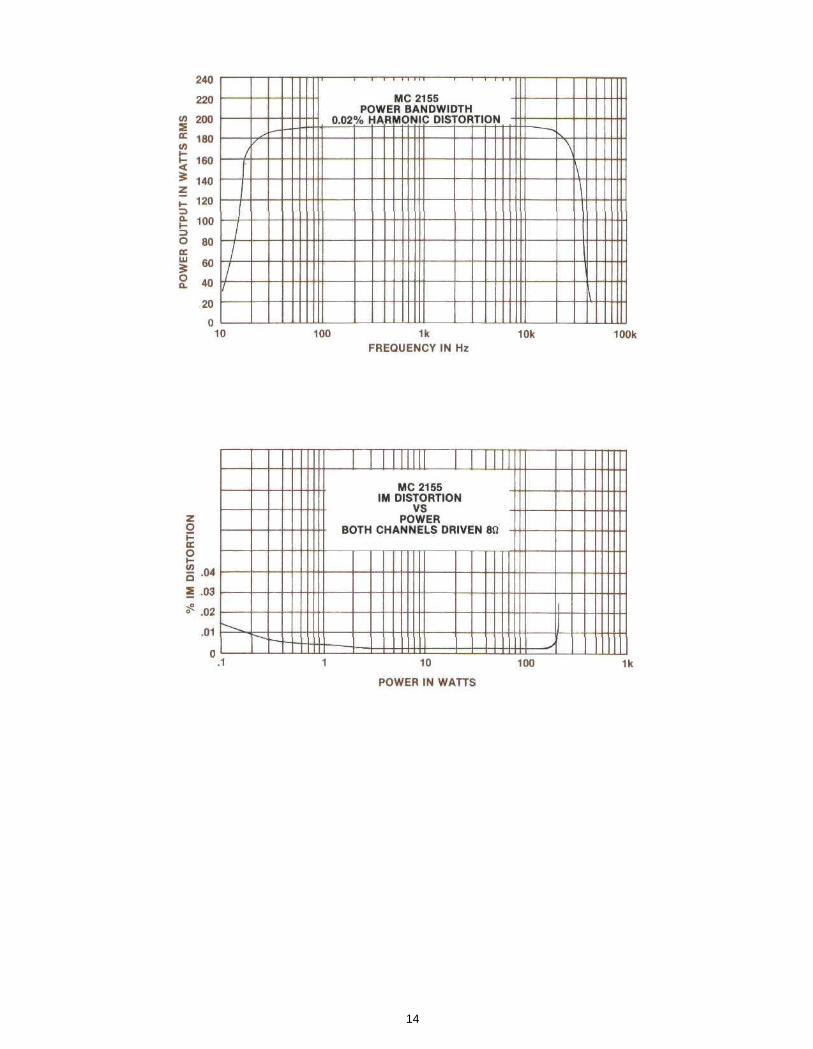
Performance Charts
PERFORMANCE CHARTS AREFOR ONE STEREO CHANNELWITH BOTH CHANNELS OPERATING.MONO OPERATION IS IDENTICALEXCEPT POWER IS DOUBLEDFOR THE SINGLE MONO OUTPUT.
13
14
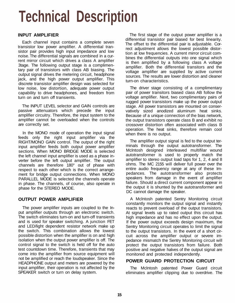
Technical DescriptionINPUT AMPLIFIER
Each channel input contains a complete seventransistor low power amplifier. A differential tran-sistor pair provides high input impedance and lownoise. The differential signals are combined in a cur-rent mirror circuit which drives a class A amplifier3tage. The following output stage is a complimen-tary pair of transistors with class AB biasing. Theoutput signal drives the metering circuit, headphonejack, and the high power output amplifier. Thisdiscrete transistor amplifier design was selected forlow noise, low distortion, adequate power outputcapability to drive headphones, and freedom fromturn on and turn off transients.
The INPUT LEVEL selector and GAIN controls arepassive attenuators which precede the inputamplifier circuitry. Therefore, the input system to theamplifier cannot be overloaded when the controlsare correctly set.
In the MONO mode of operation the input signalfeeds only the right input amplifier via theRIGHT/MONO GAIN control. The output of the rightinput amplifier feeds both output power amplifiersections. When MONO BRIDGE MODE is selectedthe left channel input amplifier is used as a phase in-verter before the left output amplifier. The outputchannels are therefore 180° out of phase withrespect to each other which is the correct arrange-ment for bridge output connections. When MONOPARALLEL MODE is selected the channels operatein phase. The channels, of course, also operate inphase for the STEREO MODE.
OUTPUT POWER AMPLIFIER
The power amplifier inputs are coupled to the In-put amplifier outputs through an electronic switch.The switch eliminates turn-on and turn-off transientsand is used for speaker switching. A junction FETand LED/light dependent resistor network make upthe switch. This combination allows the lowestpossible distortion when the amplifier is on and highisolation when the output power amplifier is off. Thecontrol signal to the switch is held off for the autotest countdown time. Therefore, transients that maycome into the amplifier from source equipment willnot be amplified or reach the loudspeaker. Since theHEADPHONE output and meters are powered by theinput amplifier, their operation is not affected by theSPEAKER switch or turn on delay system.
The first stage of the output power amplifier is adifferential transistor pair biased for best linearity.The offset to the differential pair is adjustable. Cor-rect adjustment allows the lowest possible distor-tion at low frequencies. A current mirror circuit com-bines the differential outputs into one signal whichis then amplified by a following class A voltageamplifier. Both the differential transitors and thevoltage amplifier are supplied by active currentsources. The results are lower distortion and cleanerturn-on characteristics.
The driver stage consisting of a complimentarypair of power transitors biased class AB follow thevoltage amplifier. Next, two complimentary pairs ofrugged power transistors make up the power outputstage. All power transistors are mounted on conser-vatively sized anodized aluminum heat sinks.Because of a unique connection of the bias network,the output transistors operate class B and exhibit nocrossover distortion often associated with class Boperation. The heat sinks, therefore remain coolwhen there is no output.
The amplifier output signal is fed to the output ter-minals through the output autotransformer. TheMclntosh designed interleaved multifilar woundautotransformer is used to properly match theamplifier to stereo output load taps for 1, 2, 4 and 8ohms. The MC 2155 will deliver full power over theentire audio frequency range at any of these Im-pedances. The autotransformer also protectsspeakers from damage in the event of amplifierfailure. Should a direct current component appear inthe output it is shunted by the autotransformer andDC cannot damage the speaker.
A Mclntosh patented Sentry Monitoring circuitconstantly monitors the output signal and instantlyreacts to prevent overload of the output transistors.At signal levels up to rated output this circuit hashigh impedance and has no effect upon the output.If the power output exceeds design maximum, theSentry Monitoring circuit operates to limit the signalto the output transistors. In the event of a short cir-cuit across the amplifier output or severe im-pedance mismatch the Sentry Monitoring circuit willprotect the output transistors from failure. Bothpositive and negative halves of the output signal aremonitored and protected independently.
POWER GUARD PROTECTION CIRCUIT
The Mclntosh patented Power Guard circuiteliminates amplifier clipping due to overdrive. The
15
circuit also illuminates red LIMIT indicator lampswhen the amplifier is driven beyond its maximumoutput capacity. Power Guard prevents loudspeakerdamage and eliminates harsh output distortioncaused by amplifier clipping.
The Power Guard circuit consists of a waveformcomparator which monitors the wave shape of theamplifier input and output signals. Normally there isno disparity between these signals and the com-parator produces no output. When the amplifier isdriven beyond its maximum power capacity a dif-ference will develope. If the disparity exceeds 0.5%(equivalent to 0.5% total harmonic distortion) thecomparator output causes the red LIMIT indicatorsto light. If there is a further increase in the disparitythe comparator output controls an electronic at-tenuator at the amplifier input to reduce theamplifier gain, thus holding the amplifier output toits maximum undistorted value regardless of thedegree of overdrive to the amplifier. The amplifiermay be overdriven by 20 dB before the output distor-tion exceeds 2%.
The comparator is an especially compensatedoperational amplifier integrated circuit. Its output isdetected by a full wave bridge that feeds signals tothe control circuitry for the LIMIT and NORMAL in-dicators and to the electronic attenuator at theamplifier input. The attenuator is a light emittingdiode/light dependent resistor network selectedespecially for its low distortion and time constantcharacteristics.
SYSTEM TEST CIRCUIT
When AC line power is applied to the MC 2155 theSystem Test circuit functions to verify operatingpotentials at 7 test locations within the amplifier.Upon applying power a digital display lights with thenumber 7. The digit is driven by a counter that stepsdown at a 1 second or .4 second rate. Each time thedigit changes electronic switches select the outputsof various voltage comparators connected to testpoints in the amplifier. If voltages are normal thegreen NORMAL Power Guard indicator lights, thereis an audible beep produced by an internal sounder,and the display decreases to the next test number.When the count passes number 1 the loudspeakersconnect and the display blanks off. If a fault condi-tion exists the counter stops. The digit displayed in-dicates the circuit at fault. Servicing the amplifier isthereby simplified.
The test circuit uses logic counter, BCD decoder,lamp driver, and voltage comparator integrated cir-cuits,
METER CIRCUIT
The meter circuit has three basic sections: a loga-rithmic amplifier, a full wave rectifier, and a DC amp-lifier. In the WATTS ranges, the logarithmic amplifieris used. In the DECIBEL ranges, the signal bypasses
this amplifier and goes directly to the full wave rec-tifiers through an attenuator which is controlled bythe METER RANGE switch.
The logarithmic amplifier consists of a high gainoperational amplifier with a bipolar connected sili-con diode pair as feedback elements. These diodeshave a uniform logarithmic characteristic over an 80dB range. Only 60 dB of this logarithmic range is us-ed in the MC 2155.
The full wave rectifier circuit uses an operationalamplifier with silicon diode feedback networks. Thisamplified diode circuit has nearly perfect rectifica-tion characteristics. One rectifier detects only posi-tive signals. The other responds only to negativesignals and produces a positive output. The outputsof the rectifiers are combined at the operationalamplifier output, so the highest signal, eitherpositive or negative, is the one that is indicated bythe meters. Gate diodes are used to charge a lowleakage capacitor which attains and holds a chargeduring signal peaks. The operational amplifier pro-vides a large amount of current so the capacitor cancharge suddenly. The charge on the peak holdingcapacitor is amplified in a two transistor DCamplifier which is used to drive the meter. From theoutput of this amplifier there is a DC feedback net-work that connects back to the detector to assureexcellent overall linearity and frequency response.The current drive to the meters has a peakingcapacitor to accelerate the upscale response of themeter needle. The meters also have a parallel shuntresistor to correctly damp their action. In the WATTSmode the discharge of the peak holding capacitor iscontrolled by a resistor current source. In WATTSHOLD, the resistor is disconnected so the peakreading is retained. The rate of decay is about 6 dBper minute.
POWER SUPPLY
The power supply is a conventional full wavebridge rectifier arrangement providing plus andminus 50 volts DC. Electronic regulators step downand regulate plus and minus 15 volt sources for lowlevel circuits and plus 5 volts for the logic circuits.Thermistors are used in the power transformerprimary circuit to limit the turn-on current.
16
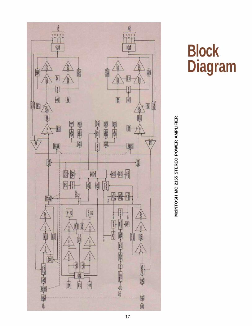
17
BlockDiagram
Mcl
NT
OS
H M
C 2
155
ST
ER
EO
PO
WE
R A
MP
LIF
IER

MclNTOSH LABORATORY INC.2 CHAMBERS ST., BINGHAMTON, N.Y. 13903-2699
607-723-3512The continuous improvement of its products is the policy ofMclntosh Laboratory Incorporated who reserve the right to
improve design without notice.Printed in U.S.A.
039478BE012004