LETTER BID PROPOSAL - La DOTD · 2009-04-14 · state of louisiana department of transportation and...
57
STATE OF LOUISIANA DEPARTMENT OF TRANSPORTATION AND DEVELOPMENT LETTER BID PROPOSAL STATE PROJECT NO. 050-07-0073 GUARD RAIL AT PORT OF GREATER BATON ROUGE ROUTE LA 1 WEST BATON ROUGE PARISH A-1 4/14/2009 8:09 AM For Information Purpose Only – Not Valid For Bid Submittal
Transcript of LETTER BID PROPOSAL - La DOTD · 2009-04-14 · state of louisiana department of transportation and...

STATE OF LOUISIANA DEPARTMENT OF TRANSPORTATION AND
DEVELOPMENT
LETTER BID PROPOSAL
STATE PROJECT NO. 050-07-0073 GUARD RAIL AT PORT OF GREATER BATON ROUGE
ROUTE LA 1 WEST BATON ROUGE PARISH
A-1 4/14/2009 8:09 AM For Information Purpose Only – Not Valid For Bid Submittal
B-1 For Information Purpose Only – Not Valid For Bid Submittal
STATE PROJECT NO. 050-07-0073 TABLE OF CONTENTS
Page No. Title Sheet ..................................................................................................................A-1 Table of Contents.......................................................................................................B-1 Notice to Contractors .................................................................................................C-1 thru C-2 Special Provisions......................................................................................................D-1 thru D-4 Supplemental Specifications:
Supplemental Specifications for 2006 Standard Specifications (08/08) ............E-1 thru E-33 Plans (10 sheets) ........................................................................................................F-1 thru F-10 Construction Proposal Returnables:
Title Sheet...........................................................................................................G-1 Bid Bond.............................................................................................................H-1 Schedule of Items ...............................................................................................I-1 thru I-2 Construction Proposal Signature and Execution Form.......................................J-1 thru J-2
For Information Purpose Only – Not Valid For Bid Submittal
C-1
NOTICE TO CONTRACTORS (10/08)
Sealed paper bids for the following project will be received by the Department of Transportation and Development (DOTD). Paper bids can be delivered to the DOTD District 61 Headquarters Administration Building, 8100 Airline Hwy, Room 4, Baton Rouge, Louisiana 70815 until 10:00 a.m on APRIL 30, 2009. Beginning at 10:00 a.m., all bids will be publicly opened and presented.No bids will be received after 10:00 a.m.. If the contractor’s license number is not printed on the outside of the bid envelope, the bid will not be opened and will be returned to the bidder. Any person requiring special accommodations shall notify DOTD at (225) 231-4100 not less than 3 business days before bid opening. STATE PROJECT NO. 050-07-0073 DESCRIPTION: GUARD RAIL AT PORT OF GREATER BATON ROUGE ROUTE: LA 1 PARISH: WEST BATON ROUGE LENGTH: 0.23 miles. TYPE: INSTALLATION OF GUARD RAIL & RELATED WORK LIMITS: State Project No.050-07-0073: ON LA 1 AT PORT OF GREATER BATON ROUGE (C.S.L.M. 8.730) ESTIMATED COST RANGE: $0 to $50,000 PROJECT ENGINEER: PALERMO, KEITH; 810 S. River Road, Port Allen, LA 70767, (225) 342-7570 PROJECT MANAGER: VOSBURG, CHAD; (225) 202-6805 COST OF PROPOSAL FORMS: FREE COST OF PLANS: Included in proposal (no additional charge). Bids must be prepared and submitted in accordance with Section 102 of the 2006 Louisiana Standard Specifications for Roads and Bridges as amended by the project specifications, and must include all information required by the proposal.
For Information Purpose Only – Not Valid For Bid Submittal
C-2
NOTICE TO CONTRACTORS (CONTINUED) Plans and specifications may be seen at the Project Engineer's office. Upon request, the Project Engineer will show the work. The U. S. Department of Transportation (DOT) operates a toll free "Hotline" Monday through Friday, 8:00 a.m. to 5:00 p.m., eastern time. Anyone with knowledge of possible bid rigging, bidder collusion, or other fraudulent activities should call 1-800-424-9071. All information will be treated confidentially and caller anonymity will be respected.
STATE PROJECT NO. 050-07-0073 SPECIAL PROVISIONS
For Information Purpose Only – Not Valid For Bid Submittal
D-1
GENERAL BIDDING REQUIREMENTS (08/06): The specifications, contract and bonds governing the construction of the work are the 2006 Edition of the Louisiana Standard Specifications for Roads and Bridges, together with any supplementary specifications and special provisions attached to this proposal. Bids shall be prepared and submitted in accordance with Section 102 of the Standard Specifications. The plans herein referred to are the plans approved and marked with the project number, route and Parish, together with all standard or special designs that may be included in such plans. The bidder declares that the only parties interested in this proposal as principals are those named herein; that this proposal is made without collusion or combination of any kind with any other person, firm, association, or corporation, or any member or officer thereof; that careful examination has been made of the site of the proposed work, the plans, Standard Specifications, supplementary specifications and special provisions above mentioned, and the form of contract and payment, performance, and retainage bond; that the bidder agrees, if this proposal is accepted, to provide all necessary machinery, tools, apparatus and other means of construction and will do all work and furnish all material specified in the contract, in the manner and time therein prescribed and in accordance with the requirements therein set forth; and agrees to accept as full compensation therefore, the amount of the summation of the products of the quantities of work and material incorporated in the completed project, as determined by the engineer, multiplied by the respective unit prices herein bid. It is understood by the bidder that the quantities given in this proposal are a fair approximation of the amount of work to be done and that the sum of the products of the approximate quantities multiplied by the respective unit prices bid shall constitute gross sum bid, which sum shall be used in comparison of bids and awarding of the contract. The bidder further agrees to perform all extra and force account work that may be required on the basis provided in the specifications. The bidder further agrees that within 15 calendar days after the contract has been transmitted to him, he will execute the contract and furnish the Department satisfactory surety bonds. If this proposal is accepted and the bidder fails to execute the contract and furnish bonds as above provided, the proposal guaranty shall become the property of the Department; otherwise, said proposal guaranty will be returned to the bidder; all in accordance with Subsection 103.04. DEFINITIONS AND TERMS (07/07): Subsection 101.03 of the Standard Specifications is amended as follows.
The definition for “Proposal/ Bid Guaranty” is deleted and following substituted. Proposal/Bid Guaranty. The required security furnished with a bid. The only form of
security acceptable is a Bid Bond. BIDDING REQUIREMENTS (07/07) Section 102 of the Standard Specifications and the Supplemental Specifications thereto, is amended as follows. Subsection 102.09, Proposal/Bid Guaranty is deleted and the following substituted. 102.09 PROPOSAL/BID GUARANTY. Each bid shall be accompanied by a proposal/bid guaranty in an amount not less than five percent of the total bid amount when the bidder’s total bid amount as calculated by the Department in accordance with Subsection 103.01
STATE PROJECT NO. 050-07-0073 SPECIAL PROVISIONS
For Information Purpose Only – Not Valid For Bid Submittal
D-2
is greater than $50,000. No proposal/bid guaranty is required for projects when the bidder’s total bid amount as calculated by the Department is $50,000 or less. The official total bid amount for projects that include alternates is the total of the bidder's base bid and all alternates bid on and accepted by the Department. The proposal/bid guaranty submitted by the bidder shall be a bid bond made payable to the contracting agency as specified on the bid bond form provided in the construction proposal. No other form of security will be accepted.
The bid bond shall be on the "Bid Bond" form provided in the construction proposal, on a form that is materially the same in all respects to the "Bid Bond" form provided, or on an electronic form that has received Department approval prior to submission. The bid bond shall be filled in completely, shall be signed by an authorized officer, owner or partner of the bidding entity, or each entity representing a joint venture; shall be signed by the surety's agent or attorney-in-fact; and shall be accompanied by a notarized document granting general power of attorney to the surety's signer. The bid bond shall not contain any provisions that limit the face amount of the bond. The bid bond will be written by a surety or insurance company that is in good standing and currently licensed to write surety bonds in the State of Louisiana by the Louisiana Department of Insurance and also conform to the requirements of LSA-R.S. 48:253. All signatures required on the bid bond may be original, mechanical reproductions, facsimiles or electronic. Electronic bonds issued in conjunction with electronic bids must have written Departmental approval prior to use. The Department will make a listing of approved electronic sureties providers on the Bidx.com site. MAINTENANCE OF TRAFFIC (11/13/08): Subsection 104.03 of the 2006 Standard Specifications is amended to include the following requirements. The contractor shall provide for and maintain through and local traffic at all times and shall conduct his operations in such manner as to cause the least possible interference with traffic at junctions with roads, streets and driveways. LANE CLOSURE RESTRICTIONS: Lane closures on the LA 1 entrance ramp will not be allowed at any time. Lane closures on the Frontage Road shall be as follows: Frontage Road shall remain open to traffic except during the times when lane closures are allowed. Lane closures will be allowed only while work is being performed. At least one lane of the Frontage Road shall remain open to traffic at all times. When lane closure is allowed, flaggers must be present. Additional work periods may be allowed at the discretion of the project engineer. Weekday lane closures will be allowed only at night and only at the following times: 9 pm Monday to 5 am Tuesday 9 pm Tuesday to 5 am Wednesday 9 pm Wednesday to 5 am Thursday 9 pm Thursday to 5 am Friday Weekend lane closures will be allowed beginning 9 pm on Friday and ending 5 am on Monday. No work shall be allowed, all lanes and ramps shall be open, and all time charges will stop during the New Years, Mardi Gras, Easter, Memorial Day, Independence Day, Labor Day, Thanksgiving, and Christmas holiday periods, as defined by the Project Engineer. No work shall be allowed, all lanes and ramps shall be open, and all time charges will stop during LSU and
STATE PROJECT NO. 050-07-0073 SPECIAL PROVISIONS
For Information Purpose Only – Not Valid For Bid Submittal
D-3
Southern University home football game weekend periods; as defined by the Project Engineer. No work shall be allowed, all lanes and ramps shall be open, and all time charges will stop during hurricane evacuation event periods, as defined by the Project Engineer.” PUBLIC CONVENIENCE AND SAFETY (09/05): Subsection 107.07 of the Standard Specifications is amended to include the following. The procurement of police officers for public safety during construction shall be in accordance with the Department’s Policy for Use of Police Officers in Construction/Maintenance Work Zones. The DOTD project engineer shall determine the need for police officers to assist in controlling traffic in a particular work zone. The number of officers needed, the tasks they will perform, and their location within the work zone will vary as a function of the zone type. Police officers shall be placed at strategic locations at times during construction as determined by the DOTD project engineer. The three types of law enforcement services are Police Presence, Police Enforcement and Police Traffic Control. Police Presence is defined as the use of police officers at the beginning of the active work zone area utilizing their blue lights to gain the attention of drivers. Police Enforcement is utilized when enforcement is required to enhance the safe operation of the work zone. Police Traffic Control is to be used in detour / diversion situations. The DOTD project engineer will extend an invitation to the appropriate Louisiana State Police (LSP) Troop Commander to attend the pre-construction conference. Prior to commencing the work on the project, the contractor shall contact the LSP Troop Commander to obtain law enforcement services of police officers during construction. If the LSP Troop is unable to provide law enforcement services for the project work zone, the LSP Troop Commander or the contractor will extend the invitation to the appropriate local law enforcement authorities. Police officers will report directly to the contractor. However, the contractor will not have the authority to direct the placement of the police officer or the patrol vehicle in situations that are contrary to established procedures and/or could endanger the police officer. The DOTD project engineer will make the final determination on all issues regarding police officer responsibility in work zones. Prior to the beginning of the shift, the contractor shall provide a daily work zone briefing to the police officer. For major changes in traffic patterns, advanced notification shall be provided to the police agency working the detail. This information should also be provided to the motoring public through the DOTD district and / or the LSP Troop. The contractor shall pay for law enforcement services provided by the police officers based on the hourly wage and vehicle rate fee schedule below. The Department will reimburse the contractor monthly for the incurred cost. The contractor shall furnish time record documentation with the request for reimbursement. The provisions of Subsection 109.04 shall not apply to this reimbursement. The agreed upon fee schedule for police officers in the work zone is as follows: $25 per vehicle per day - vehicle use fee $40 per hour per officer (one officer per vehicle) (minimum 2 hours). PROSECUTION OF WORK (12/08): Subsection 108.04, Prosecution of Work of the Standard Specifications as amended by the supplemental specifications thereto, is further amended as follows.
STATE PROJECT NO. 050-07-0073 SPECIAL PROVISIONS
108.04 PROSECUTION OF WORK. Subpart (a), General is deleted and the following substituted. (a) General: The contractor shall provide sufficient materials, equipment and labor to
complete the project in accordance with the plans and specifications within the contract time. If the completed work is behind the approved progress schedule, the contractor shall take immediate steps to restore satisfactory progress and shall not transfer equipment or forces from uncompleted work without prior notice to, and approval of, the engineer. Each item of work shall be prosecuted to completion without delay. If prosecution of the work is discontinued for an extended period of time, the contractor shall give the engineer written notice at least 24 hours before resuming operations. The contractor’s progress will be determined monthly at the time of each partial estimate, and will be based on the total amount earned by the contractor as reflected by the partial estimate. If the contractor’s progress is behind more than 20 percent behind the elapsed contract time, the contractor may be notified that he is not prosecuting the work in an acceptable manner. If requested by the Department the contractor must meet with and provide the project engineer with an acceptable written plan which details how the contractor will re-gain lost progress and prosecute remaining work. If the contractor's progress is more than 30 percent behind the elapsed contract time, the contractor and the surety will be notified that he is not prosecuting the work in an acceptable manner. The contractor must meet with and provide the project engineer with an acceptable written plan which details how the contractor will re-gain lost progress and prosecute remaining work.
Subpart (b), Disqualification is deleted and the following substituted.
(b) Disqualification: A contractor who is in default in accordance with Subsection 108.09(a)(1) of and progress is deficient by 10 percent or more shall be immediately disqualified. The contractor shall remain disqualified until the project has received a final inspection and has been recommended for final acceptance. Should the surety or the Department take over prosecution of the work, the contractor shall remain disqualified for a period of one year from the completion of the project, unless debarment proceedings are instituted.
During the period of disqualification, the contractor will not be permitted to bid on contracts nor be approved as a subcontractor on contracts. Any bid submitted by the contractor during the period of disqualification will not be considered and will be returned. PAYMENT ADJUSTMENT (05/06): Section 109, Measurement and Payment of the Standard Specifications is amended to add the following. This project is not designated for payment adjustments for asphalt cements or fuels. CONTRACT TIME (03/05): The entire contract shall be completed in all details and ready for final acceptance in accordance with Subsection 105.17(b) within FIFTEEN (15) WORKING DAYS.
D-4For Information Purpose Only – Not Valid For Bid Submittal
LOUISIANA DEPARTMENT OF TRANSPORTATION AND DEVELOPMENT
SUPPLEMENTAL SPECIFICATIONS (FOR 2006 STANDARD SPECIFICATIONS)
TABLE OF CONTENTS
PART I – GENERAL PROVISIONS
SECTION 101 – GENERAL INFORMATION, DEFINITIONS, AND TERMS Subsection 101.03 – Definitions ..........................................................................................1 SECTION 102 – BIDDING REQUIREMENTS Subsection 102.09 – Proposal / Bid Guaranty .....................................................................1 SECTION 107 – LEGAL RELATIONS AND RESPONSIBILITY TO PUBLIC Subsection 107.05 – Federal Aid Participation....................................................................2 SECTION 108 – PROSECUTION AND PROGRESS Subsection 108.04 – Prosecution of Work...........................................................................2
PART II – EARTHWORK
SECTION 202 – REMOVING OR RELOCATING STRUCTURES AND OBSTRUCTIONS
Subsection 202.06 – Plugging or Relocating Existing Water Wells ...................................2
PART III – BASE COURSES
SECTION 302 – CLASS II BASE COURSE Subsection 302.05 – Mixing ................................................................................................2 SECTION 305 – SUBGRADE LAYER Subsection 305.06 – Payment ..............................................................................................2 SECTION 307 – PERMEABLE BASES Subsection 307.02 – Materials.............................................................................................3 SECTION 308 – IN-PLACE CEMENT TREATED BASE COURSE All Subsections ....................................................................................................................3
PART V – ASPHALTIC PAVEMENTS
SECTION 502 – SUPERPAVE ASPHALTIC CONCRETE MIXTURES Subsection 502.02 – Materials.............................................................................................3 Subsection 502.14 – Lot Sizes .............................................................................................4 SECTION 508 – STONE MATRIX ASPHALT Subsection 508.01 – Description .........................................................................................5 Subsection 508.02 – Materials.............................................................................................5 Supplemental Specifications – Table of Contents (08/08)
E-1For Information Purpose Only – Not Valid For Bid Submittal

PART VI – RIGID PAVEMENT
SECTION 602 – PORTLAND CEMENT CONCRETE PAVEMENT
REHABILITATION Subsection 602.17 – Payment ..............................................................................................5
PART VII – INCIDENTAL CONSTRUCTION
SECTION 701 – CULVERTS AND STORM DRAINS All Subsections ....................................................................................................................5 SECTION 704 – GUARD RAIL Subsection 704.03 – General Construction Requirements ................................................16 SECTION 706 – CONCRETE WALKS, DRIVES AND INCIDENTAL PAVING All Subsections ..................................................................................................................16 SECTION 713 – TEMPORARY TRAFFIC CONTROL Subsection 713.06 – Pavement Markings..........................................................................18 SECTION 729 – TRAFFIC SIGNS AND DEVICES Subsection 729.02 – Materials...........................................................................................19 Subsection 729.04 – Fabrication of Sign Panels and Markers...........................................20
PART VIII – STRUCTURES
SECTION 804 – DRIVEN PILES Subsection 804.08 – Construction Requirements ..............................................................20
PART IX – PORTLAND CEMENT CONCRETE
SECTION 901 – PORTLAND CEMENT CONCRETE Subsection 901.06 – Quality Control of Concrete .............................................................20 Subsection 901.08 – Composition of Concrete..................................................................20
PART X – MATERIALS
SECTION 1001 – HYDRAULIC CEMENT Subsection 1001.01 – Portland Cement .............................................................................21 SECTION 1003 – AGGREGATES Subsection 1003.02 – Aggregates for Portland Cement Concrete and Mortar..................21 SECTION 1005 – JOINT MATERIALS FOR PAVEMENTS AND STRUCTURES Subsection 1005.04 – Combination Joint Former/Sealer ..................................................22 SECTION 1006 – CONCRETE AND PLASTIC PIPE Subsection 1006.09 – Plastic Yard Drain Pipe ..................................................................23
E-2For Information Purpose Only – Not Valid For Bid Submittal
For Information Purpose Only – Not Valid For Bid Submittal
E-3
Supplemental Specifications - Table of Contents (08/08) SECTION 1013 – METALS Subsection 1013.09 – Steel Piles .......................................................................................23 SECTION 1015 – SIGNS AND PAVEMENT MARKINGS Subsection 1015.04 – Sign Panels .....................................................................................23 Subsection 1015.05 – Reflective Sheeting.........................................................................24 Subsection 1015.11 – Preformed Plastic Pavement Marking Tape...................................28 SECTION 1020 – TRAFFIC SIGNALS Subsection 1020.01 – Traffic Signal Heads.......................................................................29 Subsection 1020.04 – Poles for Traffic Signal Systems ....................................................30

E-4 For Information Purpose Only – Not Valid For Bid Submittal
Supplemental Specifications (August 2008) Page 1 of 30
LOUISIANA
DEPARTMENT OF TRANSPORTATION AND DEVELOPMENT SUPPLEMENTAL SPECIFICATIONS
The 2006 Louisiana Standard Specifications for Roads and Bridges and supplemental specifications thereto are amended as follows.
PART I – GENERAL PROVISIONS
SECTION 101 – GENERAL INFORMATION, DEFINITIONS, AND TERMS: Subsection 101.03 – Definitions (07/07), Pages 3 – 13).
Delete the definition for “Proposal/Bid Guaranty” and substitute the following. Proposal / Bid Guaranty. The required security furnished with a bid. The only form of
security acceptable is a Bid Bond. SECTION 102 – BIDDING REQUIREMENTS: Subsection 102.09 – Proposal / Bid Guaranty (07/07), Page 19.
Delete the contents of this subsection and substitute the following. PROPOSAL/BID GUARANTY. Each bid shall be accompanied by a proposal/bid
guaranty in an amount not less than five percent of the total bid amount when the bidder’s total bid amount as calculated by the Department in accordance with Subsection 103.01 is greater than $50,000. No proposal/bid guaranty is required for projects when the bidder’s total bid amount as calculated by the Department is $50,000 or less. The official total bid amount for projects that include alternates is the total of the bidder's base bid and all alternates bid on and accepted by the Department. The proposal/bid guaranty submitted by the bidder shall be a bid bond made payable to the contracting agency as specified on the bid bond form provided in the construction proposal. No other form of security will be accepted.
The bid bond shall be on the "Bid Bond" form provided in the construction proposal, on a form that is materially the same in all respects to the "Bid Bond" form provided, or on an electronic form that has received Department approval prior to submission. The bid bond shall be filled in completely, shall be signed by an authorized officer, owner or partner of the bidding entity, or each entity representing a joint venture; shall be signed by the surety's agent or attorney-in-fact; and shall be accompanied by a notarized document granting general power of attorney to the surety's signer. The bid bond shall not contain any provisions that limit the face amount of the bond.
The bid bond will be written by a surety or insurance company that is in good standing and currently licensed to write surety bonds in the State of Louisiana by the Louisiana Department of Insurance and also conform to the requirements of LSA-R.S. 48:253.
All signatures required on the bid bond may be original, mechanical reproductions, facsimiles or electronic. Electronic bonds issued in conjunction with electronic bids must have written Departmental approval prior to use. The Department will make a listing of approved electronic sureties providers on the Bidx.com site.
E-5 For Information Purpose Only – Not Valid For Bid Submittal
Supplemental Specifications (August 2008) Page 2 of 30
SECTION 107 – LEGAL RELATIONS AND RESPONSIBILITY TO PUBLIC: Subsection 107.05 – Federal Aid Participation (04/08), Pages 57 and 58.
Delete the second paragraph. SECTION 108 – PROSECUTION AND PROGRESS: Subsection 108.04 – Prosecution of Work (03/05) Pages 74 and 75.
Add the following sentence to the third paragraph of Heading (b). Should the surety or the Department take over prosecution of the work, the contractor
shall remain disqualified for a period of one year from the completion of the project, unless debarment proceedings are instituted.
When the Department of Transportation and Development is not the contracting agency on the project, the second paragraph under Heading (c) is deleted.
PART II – EARTHWORK SECTION 202 – REMOVING OR RELOCATING STRUCTURES AND OBSTRUCTIONS: Subsection 202.06 – Plugging or Relocating Existing Water Wells (03/04), Page 105.
Delete the first sentence and substitute the following. All abandoned wells shall be plugged and sealed at the locations shown on the plans, or
as directed by the engineer, in accordance with the “Water Well Rules, Regulations, and Standards, State of Louisiana.” This document is available at the Department of Transportation and Development, Water Resources Section, P. O. Box 94245, Baton Rouge, Louisiana 70804-9245. The Water Resource Section’s telephone number is (225) 274-4172.
PART III – BASE COURSES SECTION 302 – CLASS II BASE COURSE: Subsection 302.05 – Mixing (08/06), Pages 152 and 153.
Delete the first sentence of Subheading (b)(1), In-Place Mixing, and substitute the following.
In-place mixing shall conform to Heading (a)(1) except that the percentage of Type I portland cement required will be 6 percent by volume. SECTION 305 – SUBGRADE LAYER: Subsection 305.06 – Payment (01/08), Page 184.
Delete the contents of this subsection and substitute the following. 305.06 Payment. Payment for subgrade layer will be made at the contract unit price
which includes lime, lime treatment, cement, cement treatment, water, stone, recycled portland cement concrete, crushed slag, blended calcium sulfate, asphaltic concrete, and asphalt curing membrane or prime coat, subject to the payment adjustment provisions of Section 1002 for specification deviations of asphalt materials and Subsection 303.11(a) for density deficiencies of cement treated materials. Adjustments in pay for increase or decrease in the percent cement ordered by the engineer will be in accordance with Subsection 303.13. Adjustments in pay for
E-6 For Information Purpose Only – Not Valid For Bid Submittal
Supplemental Specifications (August 2008) Page 3 of 30
increase or decrease in the percent lime ordered by the engineer will be based on the price of lime shown on paid invoices (total of all charges). The Materials and Testing Section will provide the payment adjustment percentage for properties of asphalt materials.
Payment for geotextile fabric will be included in the contract unit price for subgrade layer.
Payment will be made under: Item No. Pay Item Pay Unit 305-01 Subgrade Layer _____in (mm) Thick Square Yard (Sq m) SECTION 307 – PERMEABLE BASES: Subsection 307.02 – Materials (09/07), Pages 187 and 188.
Delete the contents of Subheading (b), Asphalt, and substitute the following. (b) Asphalt: The asphalt for asphalt treated permeable base shall be an approved polymer
modified asphalt cement, PG 76-22m, or PG 82-22rm complying with Section 1002. The percentage of asphalt cement shall be 2.0 percent to 4.0 percent by weight (mass) of the total mixture. Asphalt cement content and mixing process shall be such that all aggregates are visibly coated. The mixture shall retain 90 percent coating when tested in accordance with DOTD TR 317.
A job mix formula shall be submitted and approved in accordance with Section 502. SECTION 308 – IN-PLACE CEMENT TREATED BASE COURSE: All Subsections within Section 308 – (07/07), Pages 191 – 198.
Whenever the reference to “DOTD TR-432, Method D” is used, it shall mean “DOTD TR-432”.
PART V – ASPHALTIC PAVEMENTS SECTION 502 – SUPERPAVE ASPHALTIC CONCRETE MIXTURES: Subsection 502.02 – Materials (08/06) (11/07), Pages 210 – 213.
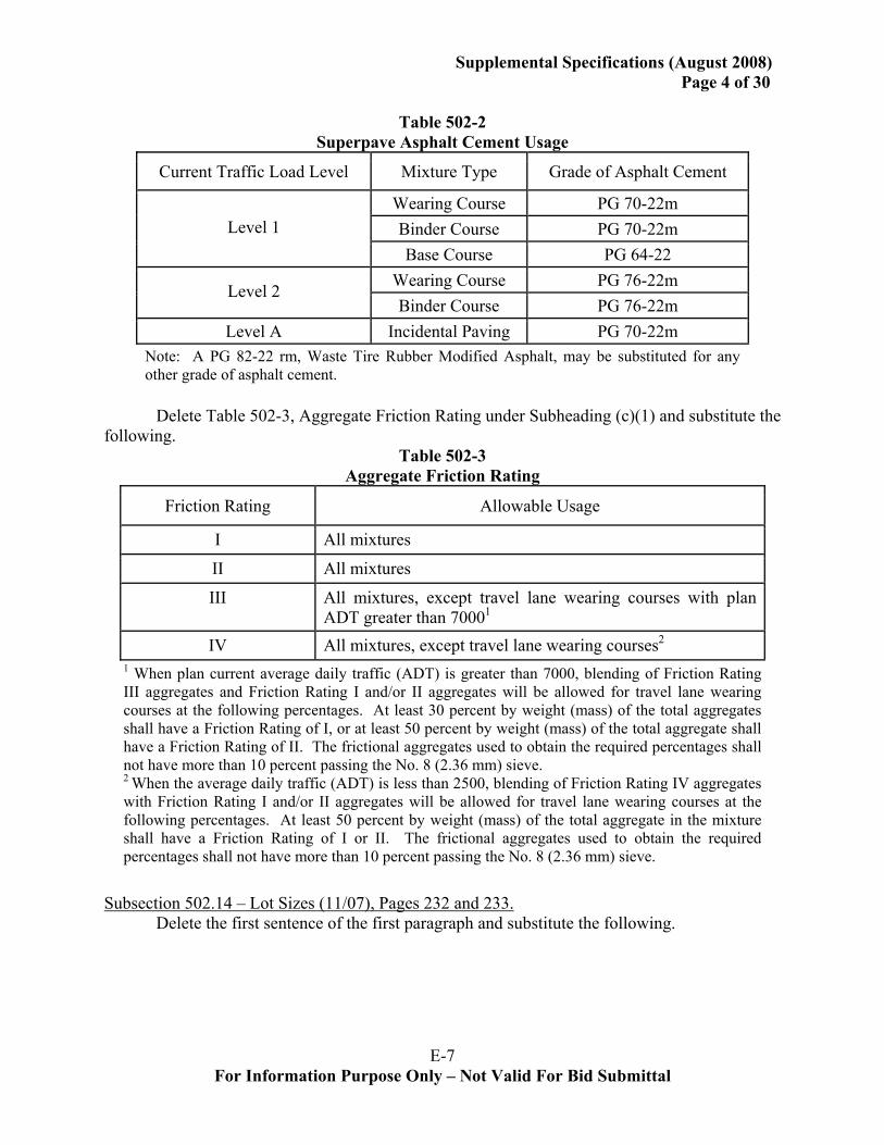
Delete Table 502-2, Superpave Asphalt Cement Usage under Subheading (a) and substitute the following.
E-7 For Information Purpose Only – Not Valid For Bid Submittal
Supplemental Specifications (August 2008) Page 4 of 30
Table 502-2 Superpave Asphalt Cement Usage
Current Traffic Load Level Mixture Type Grade of Asphalt Cement
Wearing Course PG 70-22m Binder Course PG 70-22m Level 1 Base Course PG 64-22
Wearing Course PG 76-22m Level 2 Binder Course PG 76-22m
Level A Incidental Paving PG 70-22m Note: A PG 82-22 rm, Waste Tire Rubber Modified Asphalt, may be substituted for any other grade of asphalt cement.
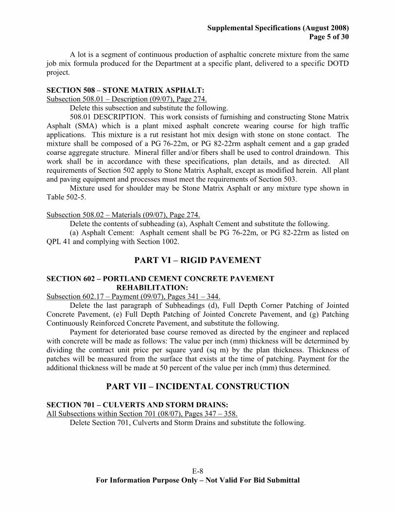
Delete Table 502-3, Aggregate Friction Rating under Subheading (c)(1) and substitute the
following. Table 502-3
Aggregate Friction Rating
Friction Rating Allowable Usage
I All mixtures
II All mixtures
III All mixtures, except travel lane wearing courses with plan ADT greater than 70001
IV All mixtures, except travel lane wearing courses2
1 When plan current average daily traffic (ADT) is greater than 7000, blending of Friction Rating III aggregates and Friction Rating I and/or II aggregates will be allowed for travel lane wearing courses at the following percentages. At least 30 percent by weight (mass) of the total aggregates shall have a Friction Rating of I, or at least 50 percent by weight (mass) of the total aggregate shall have a Friction Rating of II. The frictional aggregates used to obtain the required percentages shall not have more than 10 percent passing the No. 8 (2.36 mm) sieve. 2 When the average daily traffic (ADT) is less than 2500, blending of Friction Rating IV aggregates with Friction Rating I and/or II aggregates will be allowed for travel lane wearing courses at the following percentages. At least 50 percent by weight (mass) of the total aggregate in the mixture shall have a Friction Rating of I or II. The frictional aggregates used to obtain the required percentages shall not have more than 10 percent passing the No. 8 (2.36 mm) sieve.
Subsection 502.14 – Lot Sizes (11/07), Pages 232 and 233.
Delete the first sentence of the first paragraph and substitute the following.
E-8 For Information Purpose Only – Not Valid For Bid Submittal
Supplemental Specifications (August 2008) Page 5 of 30
A lot is a segment of continuous production of asphaltic concrete mixture from the same
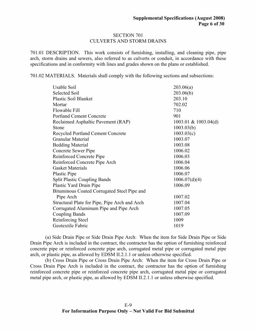
job mix formula produced for the Department at a specific plant, delivered to a specific DOTD project. SECTION 508 – STONE MATRIX ASPHALT: Subsection 508.01 – Description (09/07), Page 274.
Delete this subsection and substitute the following. 508.01 DESCRIPTION. This work consists of furnishing and constructing Stone Matrix
Asphalt (SMA) which is a plant mixed asphalt concrete wearing course for high traffic applications. This mixture is a rut resistant hot mix design with stone on stone contact. The mixture shall be composed of a PG 76-22m, or PG 82-22rm asphalt cement and a gap graded coarse aggregate structure. Mineral filler and/or fibers shall be used to control draindown. This work shall be in accordance with these specifications, plan details, and as directed. All requirements of Section 502 apply to Stone Matrix Asphalt, except as modified herein. All plant and paving equipment and processes must meet the requirements of Section 503.
Mixture used for shoulder may be Stone Matrix Asphalt or any mixture type shown in Table 502-5. Subsection 508.02 – Materials (09/07), Page 274.
Delete the contents of subheading (a), Asphalt Cement and substitute the following. (a) Asphalt Cement: Asphalt cement shall be PG 76-22m, or PG 82-22rm as listed on
QPL 41 and complying with Section 1002.
PART VI – RIGID PAVEMENT SECTION 602 – PORTLAND CEMENT CONCRETE PAVEMENT
REHABILITATION: Subsection 602.17 – Payment (09/07), Pages 341 – 344.
Delete the last paragraph of Subheadings (d), Full Depth Corner Patching of Jointed Concrete Pavement, (e) Full Depth Patching of Jointed Concrete Pavement, and (g) Patching Continuously Reinforced Concrete Pavement, and substitute the following.
Payment for deteriorated base course removed as directed by the engineer and replaced with concrete will be made as follows: The value per inch (mm) thickness will be determined by dividing the contract unit price per square yard (sq m) by the plan thickness. Thickness of patches will be measured from the surface that exists at the time of patching. Payment for the additional thickness will be made at 50 percent of the value per inch (mm) thus determined.
PART VII – INCIDENTAL CONSTRUCTION SECTION 701 – CULVERTS AND STORM DRAINS: All Subsections within Section 701 (08/07), Pages 347 – 358.
Delete Section 701, Culverts and Storm Drains and substitute the following.
E-9 For Information Purpose Only – Not Valid For Bid Submittal
Supplemental Specifications (August 2008) Page 6 of 30
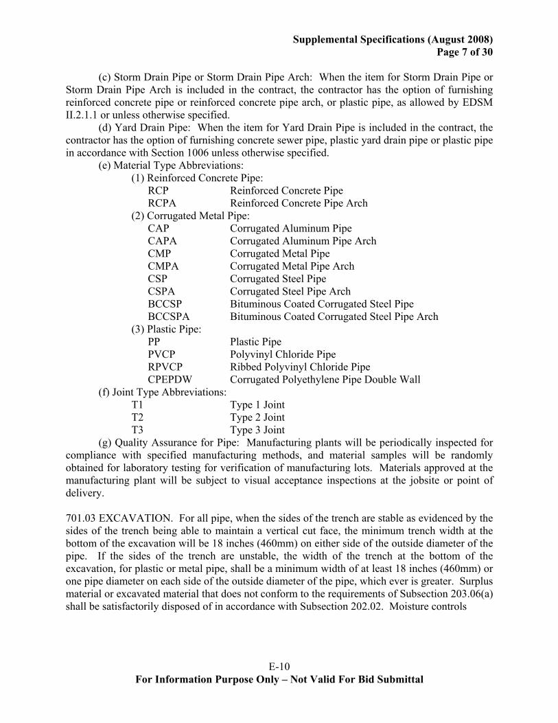
SECTION 701
CULVERTS AND STORM DRAINS 701.01 DESCRIPTION. This work consists of furnishing, installing, and cleaning pipe, pipe arch, storm drains and sewers, also referred to as culverts or conduit, in accordance with these specifications and in conformity with lines and grades shown on the plans or established. 701.02 MATERIALS. Materials shall comply with the following sections and subsections: Usable Soil 203.06(a) Selected Soil 203.06(b) Plastic Soil Blanket 203.10 Mortar 702.02 Flowable Fill 710 Portland Cement Concrete 901 Reclaimed Asphaltic Pavement (RAP) 1003.01 & 1003.04(d) Stone 1003.03(b) Recycled Portland Cement Concrete 1003.03(c) Granular Material 1003.07 Bedding Material 1003.08 Concrete Sewer Pipe 1006.02 Reinforced Concrete Pipe 1006.03 Reinforced Concrete Pipe Arch 1006.04 Gasket Materials 1006.06 Plastic Pipe 1006.07 Split Plastic Coupling Bands 1006.07(d)(4) Plastic Yard Drain Pipe 1006.09 Bituminous Coated Corrugated Steel Pipe and Pipe Arch 1007.02 Structural Plate for Pipe, Pipe Arch and Arch 1007.04 Corrugated Aluminum Pipe and Pipe Arch 1007.05 Coupling Bands 1007.09 Reinforcing Steel 1009 Geotextile Fabric 1019 (a) Side Drain Pipe or Side Drain Pipe Arch: When the item for Side Drain Pipe or Side Drain Pipe Arch is included in the contract, the contractor has the option of furnishing reinforced concrete pipe or reinforced concrete pipe arch, corrugated metal pipe or corrugated metal pipe arch, or plastic pipe, as allowed by EDSM II.2.1.1 or unless otherwise specified. (b) Cross Drain Pipe or Cross Drain Pipe Arch: When the item for Cross Drain Pipe or Cross Drain Pipe Arch is included in the contract, the contractor has the option of furnishing reinforced concrete pipe or reinforced concrete pipe arch, corrugated metal pipe or corrugated metal pipe arch, or plastic pipe, as allowed by EDSM II.2.1.1 or unless otherwise specified.
E-10 For Information Purpose Only – Not Valid For Bid Submittal
Supplemental Specifications (August 2008) Page 7 of 30
(c) Storm Drain Pipe or Storm Drain Pipe Arch: When the item for Storm Drain Pipe or
Storm Drain Pipe Arch is included in the contract, the contractor has the option of furnishing reinforced concrete pipe or reinforced concrete pipe arch, or plastic pipe, as allowed by EDSM II.2.1.1 or unless otherwise specified. (d) Yard Drain Pipe: When the item for Yard Drain Pipe is included in the contract, the contractor has the option of furnishing concrete sewer pipe, plastic yard drain pipe or plastic pipe in accordance with Section 1006 unless otherwise specified. (e) Material Type Abbreviations: (1) Reinforced Concrete Pipe: RCP Reinforced Concrete Pipe RCPA Reinforced Concrete Pipe Arch (2) Corrugated Metal Pipe: CAP Corrugated Aluminum Pipe CAPA Corrugated Aluminum Pipe Arch CMP Corrugated Metal Pipe CMPA Corrugated Metal Pipe Arch CSP Corrugated Steel Pipe CSPA Corrugated Steel Pipe Arch BCCSP Bituminous Coated Corrugated Steel Pipe BCCSPA Bituminous Coated Corrugated Steel Pipe Arch (3) Plastic Pipe: PP Plastic Pipe PVCP Polyvinyl Chloride Pipe RPVCP Ribbed Polyvinyl Chloride Pipe CPEPDW Corrugated Polyethylene Pipe Double Wall (f) Joint Type Abbreviations: T1 Type 1 Joint T2 Type 2 Joint T3 Type 3 Joint (g) Quality Assurance for Pipe: Manufacturing plants will be periodically inspected for compliance with specified manufacturing methods, and material samples will be randomly obtained for laboratory testing for verification of manufacturing lots. Materials approved at the manufacturing plant will be subject to visual acceptance inspections at the jobsite or point of delivery. 701.03 EXCAVATION. For all pipe, when the sides of the trench are stable as evidenced by the sides of the trench being able to maintain a vertical cut face, the minimum trench width at the bottom of the excavation will be 18 inches (460mm) on either side of the outside diameter of the pipe. If the sides of the trench are unstable, the width of the trench at the bottom of the excavation, for plastic or metal pipe, shall be a minimum width of at least 18 inches (460mm) or one pipe diameter on each side of the outside diameter of the pipe, which ever is greater. Surplus material or excavated material that does not conform to the requirements of Subsection 203.06(a) shall be satisfactorily disposed of in accordance with Subsection 202.02. Moisture controls
E-11 For Information Purpose Only – Not Valid For Bid Submittal
Supplemental Specifications (August 2008) Page 8 of 30
including backfill materials selection and dewatering using sumps, wells, well points or other approved processes may be necessary to control excess moisture during excavation, installation of bedding, over-excavated trench backfilling, pipe placement and pipe backfill. (a) Over-excavation: When unsuitable soils as defined in Subsection 203.04 or a stable, non-yielding foundation cannot be obtained at the established pipe grade, or at the grade established for placement of the bedding, unstable or unsuitable soils below this grade shall be removed and replaced with granular material meeting the requirements of Subsection 1003.07, bedding materials meeting the requirements of Subsection 1003.08 or Type A backfill. All granular, backfill materials placed below the established pipe or bedding grade shall be placed in lifts not exceeding 8 inches (200 mm) thick and sufficiently compacted by hand or a dynamic mechanical hand compaction device over the surface of each lift to form a stable, non-yielding foundation at the surface of the established bedding or pipe grade. When rock is encountered, it shall be removed below grade and replaced with material complying with Subsection 1003.07, bedding materials meeting the requirements of Subsection 1003.08 or Type A backfill. The compacted earth cushion shall have a thickness under the pipe of at least 1/2 inch per foot (40 mm/m) of fill height over the top of the pipe with a minimum thickness of 8 inches (200 mm). All granular, backfill materials placed below the established pipe or bedding grade shall be placed in lifts not exceeding 8 inches (200 mm) thick and sufficiently compacted by hand or a dynamic mechanical hand operated compaction device over the surface of each lift to form a stable, non-yielding foundation at the surface of the established bedding or pipe grade. Materials used to backfill in an over-excavated portion of a trench do not require encasement in a Geotextile Fabric. Density of approved materials placed in over-excavated trenches will not be measured or determined. 701.04 FORMING PIPE BED. Bedding material, when specified, shall be constructed in accordance with Section 726. Materials allowed for bedding shall be as specified in Subsection 1003.08 or may be Type A backfill materials. When bedding materials are specified, additional excavation shall be performed below established pipe grade and the bedding material placed in lifts not exceeding 8 inches (200 mm) thick and lightly compacted by hand or a dynamic hand compaction device over the surface of each lift. When the bottom of the pipe is not laid in a trench but is constructed above natural soils, a uniform bed shall be constructed as specified for the bottom of a trench. Density of approved bedding materials will not be measured or determined. 701.05 LAYING PIPE. Pipe laying shall begin at the downstream end of the line. The pipe shall be in contact with the foundation throughout its length. Bell or groove ends of pipe and outside circumferential laps of riveted metal pipe shall be placed facing upstream. Riveted seam metal pipe shall be placed with longitudinal laps at sides. Pipes in each continuous line shall have the same wall thickness. Metal pipes provided with lifting lugs shall be handled only by these lugs.
E-12 For Information Purpose Only – Not Valid For Bid Submittal
Supplemental Specifications (August 2008) Page 9 of 30
After pipe has been laid and before backfill is placed, the engineer will inspect the pipe
for alignment, grade, integrity of joints, and coating damage. 701.06 JOINING PIPE. (a) Joint Usage: (1) Type 1 (T1) joints shall be used for side drains under drives and similar installations. (2) Type 2 (T2) joints shall be used for cross drains under roadways, including turnouts. (3) Type 3 (T3) joints shall be used for closed storm drain systems, flumes and siphons. (b) Concrete Pipe: Concrete pipe may be either bell and spigot, or tongue and groove. The method of joining pipe sections shall be such that ends are fully entered and inner surfaces are flush and even. An approved mechanical pipe puller shall be used for joining pipes over 36 inches (900 mm) in diameter. For pipe 36 inches (900 mm) or less in diameter, any approved method for joining pipe may be used which does not damage the pipe. Joints shall comply with Subsection 1006.05, and shall be sealed with gasket material installed in accordance with the manufacturer's recommendations. (c) Metal Pipe: Metal pipe shall be firmly joined by coupling bands. Bands shall be centered over the joint. For Type 1 joints, approved gasket material shall be placed in one corrugation recess on each side of the joint at the coupling band and on each band connection in such manner to prevent leakage. When Type 2 or 3 joints are specified, joining of metal pipe sections shall conform to the following provisions: (1) General: Band joints shall be sealed with gasket material. Gasket material shall be placed in accordance with the plan details. (2) Circular Section: Connecting bands shall be of an approved design and shall be installed in accordance with plan details. (3) Arch Section: Connecting bands shall be a minimum of 12 inches (300 mm) wide for pipe arch less than 36 inches (900 mm) round equivalent diameter, and a minimum of 21 inches (525 mm) wide for 36 inches (900 mm) round equivalent diameter pipe arch and greater. Bands shall be connected at the ends by approved angle or strap connections. Connecting bands used for 36 inches (900 mm) round equivalent diameter pipe arch and above shall be 2-piece bands. (d) Plastic Pipe: Joints for plastic pipe shall be either bell and spigot or split coupling bands. (1) Bell and Spigot Type Joint System: The method of joining pipe sections shall be such that ends are fully entered and inner surfaces are flush and even. Any approved method for joining pipe may be used which does not damage the pipe. Joints shall be approved and shall be sealed with a gasket system utilizing gasket material complying with Subsection 1006.06(a).
E-13 For Information Purpose Only – Not Valid For Bid Submittal
Supplemental Specifications (August 2008) Page 10 of 30
(2) Split Coupling Type Joint System: Split coupling bands shall comply with all dimensional and material requirements of Subsection 1006.07. The bands shall be centered over the joint. The split coupling band shall be secured to the pipe with a minimum of five stainless steel or other approved corrosion resistant bands. Joints shall be approved and shall be sealed with gasket material. Gasket material shall be placed in the first two corrugation recesses on each side of the pipe connections. Gasket material shall also be placed on each band connection to prevent leakage. When flexible plastic gasket material is used it shall be a minimum of 1/2 inch (13 mm) in size. The bands shall be tightened to create overlap of the band and shall adequately compress the gasket material. (e) Connections: Approved connections shall be used when joining new pipes to existing pipes. When concrete collars are required in order to extend the ends of existing pipes that have been damaged or to join different types or sizes of pipes, the concrete collars shall be constructed in accordance with plan details, the applicable requirements of Section 901, and as directed. (f) Geotextile Fabric, Pipe Joints: For concrete, metal and plastic pipes, Types 2 and 3 joints shall be wrapped with geotextile fabric for a minimum of 12 inches (300 mm) on each side of joint for pipe 36 inches (900 mm) or less in diameter and a minimum of 18 inches (450 mm) on each side of the joint for pipe greater than 36 inches (900 mm) in diameter. Ends of the fabric shall be lapped at least 10 inches (250 mm). The edges and ends of fabric shall be suitably secured for the entire circumference of the pipe. 701.07 RELAYING PIPE. If specified or directed, existing pipes shall be removed and suitable sections relaid as specified for new pipes. 701.08 BACKFILLING. (a) General: Prior to backfilling, pipes found to be damaged or out of alignment or grade shall be removed and reinstalled, or replaced. Type A backfill material shall be stone, recycled portland cement concrete, flowable fill, or RAP. Type B backfill materials are selected soils. Where Type B backfill materials are called for, Type A backfill materials may be substituted. When corrugated metal pipe is used, the backfill material shall be tested and shall have a resistivity greater than 1500 ohm-cm and a pH greater than 5 when tested in accordance with DOTD TR 429 and DOTD TR 430 respectively. When Type A backfill material is used, geotextile fabric surrounding this backfill shall be placed in accordance with Subsection 726.03 between the aggregate backfill material and all other natural or placed soils in the trench or embankment. Care shall be taken to prevent damage to geotextile fabric during placement of backfill material. For concrete pipe, the fabric shall enclose not only the initial backfill but shall be wrapped over the top of the pipe with at least 12 inches (300 mm) of overlap. When a trench box or trench sheeting is used in unstable soils and/or for worker safety, and when moved during backfilling operations, filling and additional compaction of the disturbed zone of backfill must take place immediately and in a manner acceptable to the engineer.

E-14 For Information Purpose Only – Not Valid For Bid Submittal
Supplemental Specifications (August 2008) Page 11 of 30
Initial backfill is a structural backfill encasing the pipe from the bottom of the pipe to the springline for concrete pipe and to a point one foot (0.3 m) above the top of the pipe for both metal and plastic pipe. Final backfill is not a structural backfill and shall extend from the top of the initial backfill to the top of the natural ground or subgrade in cut areas or to the top of existing ground in fill areas. Any fill required above the final backfill is considered and treated as embankment. (b) Backfill Applications: For projects using A+B+C bidding method where rigid and flexible pavement alternates are considered, backfill application (2) below, “Cross Drains Under Flexible Pavements”, shall apply for either rigid or flexible pavements. (1) Under Concrete Pavements: Type B backfill may be used as initial and final backfill for all pipes, culverts or drains under concrete pavements. Placement and compaction shall be as specified in Heading (d) below. (2) Cross Drains Under Flexible Pavements: All reaches, exclusive of those portions of the pipe which are under shoulders, of cross drains and all other culverts, pipes or drains that cross the centerlines of the new roadway or centerlines of existing roadways, such as intersections and are under flexible pavements shall receive an initial backfill of Type A material. Type B backfill materials may be used as final backfill for all pipes. Placement and compaction shall be as specified in Heading (c) and (d) below. Where the subgrade is above existing ground, embankment material as specified for the remainder of the project shall be used from the top of the final backfill to the top of the established embankment grade. (3) Other Drains Under Flexible Pavements: All reaches of all culverts, pipes or drains under flexible pavements that do not cross the centerlines of new roadway or centerlines of existing roadways, and exclusive of those portions of the pipe which are totally under shoulders, shall receive an initial and final backfill of Type B material. Placement and compaction shall be as specified in Heading (d) below. Where the subgrade is above existing ground, embankment material as specified for the remainder of the project shall be used from the top of the final backfill to the top of the established embankment grade. (4) Other Areas: All culverts, pipes or drains in nonpaved areas or paved areas that serve as driveways or shoulders shall receive an initial and final backfill of Type B material. Placement and compaction shall be as specified in Heading (d) below. (5) Pipes Subject to Construction Traffic; The embankment or pipe backfill shall be constructed to a minimum of 24 inches (600 mm) over the pipe before heavy construction equipment is allowed to cross the installation. Where practical, installations with less than 24 inches (600 mm) of cover over the top of the pipe shall be constructed after heavy hauling is completed over the pipe location. After completion of hauling operations, the contractor shall remove excess cover material. Pipe damaged by hauling and backfilling operations shall be removed and reinstalled, or replaced, at no direct pay. (c) Placement and Compaction; Type A Backfill: For all pipes, culverts and conduits under paved and nonpaved areas, where Type A backfill material is used, the Type A backfill shall be thoroughly hand compacted under the pipe haunches and then dynamically compacted in layers not exceeding 8 inches (200 mm) compacted thickness. Compaction under the haunches of the pipe shall initially be by hand tamping or other acceptable means, until a level is reached that the dynamic tamping can commence. Each lift shall be compacted by applying at least eight
E-15 For Information Purpose Only – Not Valid For Bid Submittal
Supplemental Specifications (August 2008)
Page 12 of 30 passes of a hand operated, dynamic mechanical compaction device over the surface of each lift. With approval of the engineer, layer thickness may be increased to 12 inches (300 mm) with verification of satisfactory installation and performance. If flowable fill is used it shall be furnished, placed and consolidated in accordance with Section 710. The contractor shall control placement operations during initial backfill operations so as not to damage protective coatings on metal pipes. The contractor shall repair damaged coatings at no additional pay. (d) Placement and Compaction; Type B Backfill: For all pipes, culverts and conduits, where Type B backfill is allowed, the Type B material shall be placed in layers not exceeding 8 inches (200 mm) compacted thickness. Compaction shall be with suitable mechanical equipment. With approval of the engineer, layer thickness may be increased to 12 inches (300 mm) with verification of satisfactory installation and performance. (e) Placement and Compaction; Trenchless or Partial Trench Condition: All pipes, culverts, drains and conduits placed with any portion of the pipe above existing ground must also comply with Subsections (a),(b) (c) and (d) above for the portion of the pipe within a trench and that portion of the pipe not constructed in a trench. The width of initial and final backfill of that portion above existing ground and not within a trench will be constructed to such a width that the requirements for placement, compaction and density are met. (f) Density Requirements: The in place density of Type A backfill materials and bedding materials, will not be measured or determined. Type A backfill, exclusive of RAP and flowable fill, shall be placed at or near optimum moisture content determined in accordance with DOTD TR 415 or 418. RAP materials shall be placed and compacted in a slightly moist condition. The maximum dry density of initial or final Type B backfill under all paved areas which are to be under traffic will be determined in accordance with DOTD TR 415 or TR 418 and in-place density determined in accordance with DOTD TR 401. Initial and final Type B backfill under all paved areas, under traffic, shall be placed at or near optimum moisture content determined in accordance with DOTD TR 415 or TR 418. Each layer shall be compacted by approved methods prior to the placement of a subsequent layer. The engineer will approve the compaction method based upon validation that such method, including moisture control, will achieve at least 95 percent of maximum dry density as determined in accordance with DOTD TR 401. With approval of the engineer, density testing may be waived on subsequent layers with backfill installation in accordance with approved compaction methods and continued satisfactory performance. Initial and final backfill in unpaved areas or paved areas such as shoulders or driveways, shall be placed evenly and compacted along the length of the culvert, pipe or drain from the top of the initial backfill to the top of the subgrade. Layered backfill shall be compacted at least to the density of the adjoining existing soils or the compaction required of the laterally adjoining layers of soil immediately outside the trench for embankment elevations. Initial and final backfill shall be placed and compacted at or near optimum moisture content determined in accordance with DOTD TR 415 or TR 418. 701.09 INSPECTION OF PIPES. After completion of embankment and prior to roadway surfacing, the engineer shall inspect pipes for proper alignment and integrity of joints. Any misaligned pipe or defective joints shall be corrected by the contractor at no direct pay.
E-16 For Information Purpose Only – Not Valid For Bid Submittal
Supplemental Specifications (August 2008) Page 13 of 30
(a) Plastic Pipe: Installed plastic pipe shall be tested to ensure that vertical deflections do not exceed 5.0 percent. Maximum allowable deflections shall be governed by the mandrel requirements stated herein. Deflection tests shall be performed no sooner than 30 calendar days after installation and compaction of backfill. The pipe shall be cleaned and inspected for offsets and obstructions prior to testing. For pipe 36 inches (900 mm) and less in diameter, a mandrel shall be pulled through the pipe by hand to ensure that maximum allowable deflections have not been exceeded. The mandrel shall be approved by the engineer prior to use. Use of an unapproved mandrel or a mandrel altered or modified after approval will invalidate the test. If the mandrel fails to pass, the pipe is overdeflected. Unless otherwise permitted, overdeflected pipe shall be uncovered and, if not damaged, reinstalled. Damaged pipe shall not be reinstalled, but shall be removed and replaced with new pipe. Any pipe subjected to any method or process other than removal, which attempts, even successfully, to reduce or cure any overdeflection, shall be removed and replaced with new pipe. The mandrel shall be a rigid, nonadjustable, odd-numbered legged (minimum 9 legs) mandrel having a length not less than its nominal diameter or 24 inches (600 mm), whichever is less. The minimum diameter at any point shall be 5.0 percent less than the base inside diameter of the pipe being tested. The mandrel shall be fabricated of steel, aluminum or other approved material fitted with pulling rings at each end. The nominal pipe size and outside diameter of the mandrel shall be stamped or engraved on some segment other than a runner. A suitable carrying case shall be furnished. For pipe larger than 36 inches (900 mm) in diameter, deflection shall be determined by a method approved by the engineer. If a mandrel is selected, the minimum diameter, length, and other requirements shall conform to the above requirements. Mandrel testing shall be conducted by the contractor in the presence of the engineer. Mandrel testing shall be at no direct pay. (b) Metal Pipe: If the inside diameter of metal pipe or rise dimension of metal pipe arch deflects more than 5.0 percent from original dimensions, they shall be removed and reinstalled, unless they do not rebound or are damaged. Pipe or pipe arch which are damaged or do not rebound shall be removed and replaced at no direct pay. Measurement of deflection will be made by the engineer away from rerolled ends. 701.10 CLEANING PIPES. (a) Existing Pipes: Pipes designated to be cleaned shall be cleaned of soil, debris and other materials to the invert of the pipe. Designated pipes shall be cleaned by approved methods that will not damage the pipes. Any damage caused by the contractor's operations shall be satisfactorily repaired at no direct pay. Removed soil, debris and other materials shall be disposed of in accordance with Subsection 202.02 or as otherwise approved in writing.
(a) Contractor Installed Pipes: Prior to final acceptance, pipes shall be cleaned of all debris and soil to the invert of the pipe at no direct pay.
E-17 For Information Purpose Only – Not Valid For Bid Submittal
Supplemental Specifications (August 2008) Page 14 of 30
Removed soil, debris and other materials shall be disposed of in accordance with Subsection 202.02 or as otherwise approved in writing. 701.11 STUBBING AND PLUGGING PIPES. When it is required that pipes be plugged, such plugs shall be constructed of Class R concrete complying with Section 901. Thickness of plug and method of construction shall be as directed. When new pipes are to be stubbed into new or existing pipes or other structures, the connection shall be made with approved mortar complying with Subsection 702.02. 701.12 MEASUREMENT. Pipe, both new and relaid, will be measured in linear feet (lin m) as follows unless stated otherwise. (a) Pipe not confined by fixed structures will be measured by the number of joints at the nominal length of each joint. (b) Pipe confined by fixed structures will be measured along the pipe between the termini of pipe in structure walls. (c) Pipe confined by a fixed structure on one end and unconfined at the other end will be measured along the pipe from the terminus of pipe in the structure wall to the unconfined end of pipe. (d) Fabricating of pipe tees, elbows and other fittings will be measured per each fitting. The length of pipe in such fittings will be included in the pay length measurement of pipes of which they form a part. (e) Excavation required for installation of pipes will not be measured for payment, except as otherwise specified in Subsection 203.14. (f) Furnishing and placing backfill material below existing ground level for pipes will not be measured for payment. Backfill material needed to complete backfill above natural ground and around pipes that extend above natural ground will be measured and payment will be made under applicable earthwork items. When specified, flowable fill will be measured and paid for in accordance with Section 710. (g) Plugging and stubbing of pipes will not be measured for payment. (h) Cleaning existing pipes will be measured by the length of pipe cleaned and accepted. (i) Concrete collars will be measured per each. 701.13 PAYMENT. (a) Payment for pipe will be made at the contract unit price per linear foot (lin m) of the types and sizes specified. When plastic pipe is specified on the plans or elected to be used by the contractor, payment will be made at the contract unit price per linear foot (lin m) of the types and sizes specified in accordance with the payment schedule of Table 701-1.
E-18 For Information Purpose Only – Not Valid For Bid Submittal
Supplemental Specifications (August 2008) Page 15 of 30
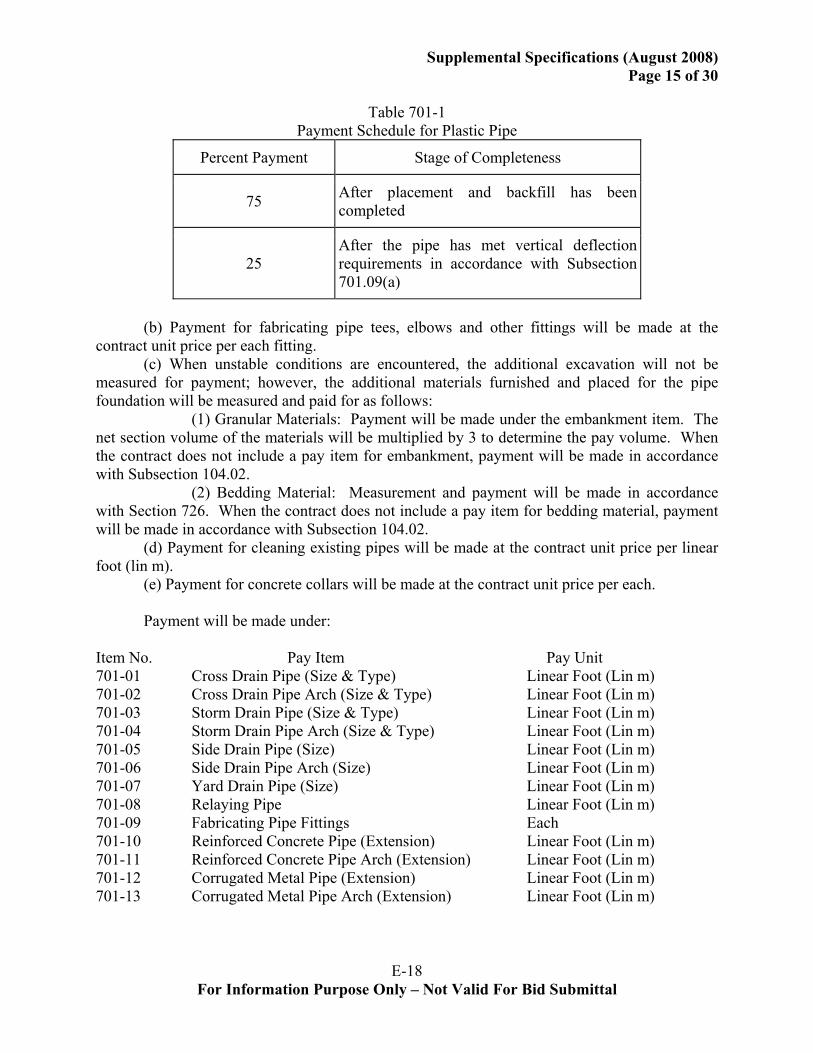
Table 701-1
Payment Schedule for Plastic Pipe
Percent Payment Stage of Completeness
75 After placement and backfill has been completed
25 After the pipe has met vertical deflection requirements in accordance with Subsection 701.09(a)
(b) Payment for fabricating pipe tees, elbows and other fittings will be made at the contract unit price per each fitting. (c) When unstable conditions are encountered, the additional excavation will not be measured for payment; however, the additional materials furnished and placed for the pipe foundation will be measured and paid for as follows: (1) Granular Materials: Payment will be made under the embankment item. The net section volume of the materials will be multiplied by 3 to determine the pay volume. When the contract does not include a pay item for embankment, payment will be made in accordance with Subsection 104.02. (2) Bedding Material: Measurement and payment will be made in accordance with Section 726. When the contract does not include a pay item for bedding material, payment will be made in accordance with Subsection 104.02. (d) Payment for cleaning existing pipes will be made at the contract unit price per linear foot (lin m). (e) Payment for concrete collars will be made at the contract unit price per each. Payment will be made under: Item No. Pay Item Pay Unit 701-01 Cross Drain Pipe (Size & Type) Linear Foot (Lin m) 701-02 Cross Drain Pipe Arch (Size & Type) Linear Foot (Lin m) 701-03 Storm Drain Pipe (Size & Type) Linear Foot (Lin m) 701-04 Storm Drain Pipe Arch (Size & Type) Linear Foot (Lin m) 701-05 Side Drain Pipe (Size) Linear Foot (Lin m) 701-06 Side Drain Pipe Arch (Size) Linear Foot (Lin m) 701-07 Yard Drain Pipe (Size) Linear Foot (Lin m) 701-08 Relaying Pipe Linear Foot (Lin m) 701-09 Fabricating Pipe Fittings Each 701-10 Reinforced Concrete Pipe (Extension) Linear Foot (Lin m) 701-11 Reinforced Concrete Pipe Arch (Extension) Linear Foot (Lin m) 701-12 Corrugated Metal Pipe (Extension) Linear Foot (Lin m) 701-13 Corrugated Metal Pipe Arch (Extension) Linear Foot (Lin m)
E-19 For Information Purpose Only – Not Valid For Bid Submittal
Supplemental Specifications (August 2008) Page 16 of 30
701-14 Cleaning Existing Pipes Linear Foot (Lin m) 701-15 Concrete Collar Each 701-16 Plastic Pipe (Extension) Linear Foot (Lin m) SECTION 704 – GUARD RAIL: Subsection 704.03 – General Construction Requirements (01/05), Pages 368 and 369.
Add the following to Heading (d), Guard Rail End Treatments. All end treatments shall bear a label indicating the manufacturer and exact product name
of the end treatment along with its assigned NCHRP 350 test level. This label shall resist weathering and shall be permanently affixed to the railing in such a way as to be readily visible. SECTION 706 – CONCRETE WALKS, DRIVES AND INCIDENTAL PAVING: All Subsections within Section 706 (04/08), Pages 375 – 377.
Delete Section 706, Concrete Walks, Drives and Incidental Paving and substitute the following.
SECTION 706 CONCRETE WALKS, DRIVES AND INCIDENTAL PAVING
706.01 DESCRIPTION. This work consists of furnishing and constructing portland cement concrete walks, handicapped curb ramps, drives and incidental paving slabs in accordance with these specifications and in conformity with lines, grades and dimensions shown on the plans or established. 706.02 MATERIALS. Materials shall comply with the following Section or Subsections. Portland Cement Concrete (Class M) 901 Joint Filler 1005.01(c) Reinforcing Steel 1009.01 Curing Materials 1011.01 706.03 CONSTRUCTION REQUIREMENTS. (a) Excavation: Excavation shall be made to required depth and width. The top of the subgrade shall be shaped and compacted to a firm, even surface conforming to the section shown on the plans. Unsuitable material shall be removed and disposed of in accordance with Subsection 202.02 and replaced with approved material at no direct pay. (b) Forms: Forms shall be of wood or metal and shall extend the full depth of concrete. Forms shall be straight, clean and of sufficient strength to resist the pressure of concrete. Bracing of forms shall be such that forms remain in horizontal and vertical alignment until their removal. Concrete may be placed by slip-form methods. Slip-formed concrete shall be placed with an approved machine designed to spread, vibrate, consolidate and finish concrete in one pass of the machine in such manner that minimum hand finishing is necessary. Sliding forms shall be
E-20 For Information Purpose Only – Not Valid For Bid Submittal
Supplemental Specifications (August 2008)
Page 17 of 30
rigidly held together to prevent spreading of forms. After the passing of the side forms there shall be no noticeable slumping of concrete. (c) Subgrade: The subgrade shall be thoroughly moistened immediately prior to placing concrete. (d) Placing and Finishing: Concrete shall be placed on the subgrade, struck off to required thickness and tamped sufficiently to bring the mortar to the surface. The surface shall be finished with a wood float or steel trowel followed by brushing to a slightly rough finish. Joints and edges shall be rounded with an edging tool having a 1/4-inch (6 mm) radius. (e) Joints: (1) Expansion Joints: Expansion joints shall be filled with 1/2 inch (13 mm) thick preformed expansion joint filler. Expansion joints shall be installed at maximum 100-foot (30 m) intervals, and between intersecting paving and any fixed structure such as a building, bridge or curbing, and between intersecting paving and the handicapped curb ramps. Expansion joint material shall extend for the full width and depth of paving. (2) Weakened Plane: Weakened planes shall be formed by a jointing tool or other acceptable means. Weakened planes shall extend into concrete for at least 1/4 of the depth and shall be approximately 1/8 inch (3 mm) wide. a. Walks: Spacing of weakened planes for walks shall be equal to the width of walk. b. Drives: A longitudinal weakened plane shall be formed along the centerline of drives more than 16 feet (5 m) wide, and transverse weakened planes shall be formed at not more than 16-foot (5 m) intervals. c. Incidental Paving: Weakened planes for incidental paving shall be formed at intervals not exceeding 30 times the thickness of the concrete in length or width. Incidental paving poured adjacent to jointed concrete shall be jointed to match existing joints, with intermediate joints formed as necessary not to exceed the maximum joint spacing. (3) Construction Joints: Construction joints shall be formed around manholes, utility poles, etc., extending into paving and 1/4 inch (6 mm) thick preformed expansion joint filler shall be installed in these joints. (4) Tie-ins: Tie-ins of existing concrete shall be made by full depth sawing at no direct pay. (f) Curing: Concrete shall be cured in accordance with Subsection 601.10. (g) Detectable Warning Surface for Handicap Ramps and At-Grade Sidewalk Intersections: Sidewalks, when intersecting with roadways, shall be equipped with a detectable warning surface system consisting of raised truncated domes as a transition between the sidewalk and the street as required by the Americans with Disabilities Act, 28 CFR Part 36, ADA Standards for Accessible Design. Detectable warnings (truncated domes) shall be installed on the ramp surface over the full width of the ramp throat for a distance of 24 inches (600 mm) in the direction of travel from the back of the curb. Detectable warnings (truncated domes) shall also be installed on at-grade sidewalks intersecting with roadways for a distance of 36 inches (900 mm) in the direction of travel from the end of the sidewalk. Truncated domes shall be laid out on a square grid in order to allow enough space for wheelchairs to roll between the domes.
E-21 For Information Purpose Only – Not Valid For Bid Submittal
Supplemental Specifications (August 2008) Page 18 of 30
Light reflectance of the truncated domes and the underlying surface must meet the 70 percent contrast requirement of ADAAG. 706.04 MEASUREMENT. Quantities of concrete walks, drives and incidental paving slabs for payment will be the design quantities as specified on the plans and adjustments thereto. Design quantities will be adjusted if the engineer makes changes to adjust to field conditions, if design errors are proven or if design changes are made. Design areas are based on the horizontal dimensions shown on the plans. Excavation, backfill, reinforcing steel and joint materials will not be measured for payment. Handicapped curb ramps, including the detectable surface warning system, will be measured per each. Detectable surface warning systems for at-grade sidewalk intersection will not be measured for payment. 706.05 PAYMENT. Payment for concrete walks, drives and incidental paving will be made on a lot basis at the contract unit price per square yard (sq m), adjusted in accordance with the following provisions. Payment for each lot will be made in accordance with Table 901-6. Size, sampling, and testing of each concrete lot shall be in accordance with the Materials Sampling Manual. Payment for handicapped curb ramps, including the detectable surface warning system, will be made by each and shall include, but not limited to, curb transitions, detectable warning system, gutter, landing and base. Payment will be made under: Item No. Pay Item Pay Unit 706-01 Concrete Walk ( inch (mm) Thick) Square Yard (Sq m) 706-02 Concrete Drive ( inch (mm) Thick) Square Yard (Sq m) 706-03 Incidental Concrete Paving ( inch (mm) Thick Square Yard (Sq m) 706-04 Handicapped Curb Ramps Each SECTION 713 – TEMPORARY TRAFFIC CONTROL: Subsection 713.06 – Pavement Markings (08/06), Pages 400 – 403.
Delete Table 713-1, Temporary Pavement Markings and substitute the following.

E-22 For Information Purpose Only – Not Valid For Bid Submittal
Supplemental Specifications (August 2008) Page 19 of 30
Table 713-1
Temporary Pavement Markings1,2
Two-lane Highways Undivided Multilane
Highways
Divided Multilane Highways
ADT<1500; or ADT>1500 and time<3 days
Lane lines 4-foot (1.2 m) tape on 40-foot (12 m) centers; with "Do Not Pass" and "Pass With Care" signs as required
ADT>1500; Time>3 days and<2 weeks
Lane lines 4-foot (1.2-m) tape on 40-foot (12-m) centers with no passing zone markings
SHORT TERM All ADT's
with time <2 weeks
Lane lines 4-foot (1.2m) tape on 40-foot (12 m) centers; double yellow centerline
Lane lines 4-foot (1.2 m) tape on 40-foot (12 m) centers
LONG TERM
All ADT's with time >2 weeks
Standard lane lines, no-passing zone markings, legends and symbols and when pavement width is 22 feet (6.7 m) or greater, edge lines
Standard lane lines, centerlines, edge lines, and legends and symbols
Standard lane lines, centerlines, edge lines, and legends and symbols.
1No-passing zones shall be delineated as indicated whenever a project is open to traffic.2On all Asphaltic Surface Treatments that are open to traffic and used as a final wearing course or as an interlayer, temporary pavement markings (tabs) on 20-foot (6 m) centers shall be used, in lieu of the 4-foot (1.2 m) tape, on 40-foot (12 m) centers.
SECTION 729 – TRAFFIC SIGNS AND DEVICES: Subsection 729.02 – Materials (04/08), Pages 456 and 457.
Delete the contents of Heading (a), Sign and Marker Sheeting, and substitute the following.
(a) Sign and Marker Sheeting: Sheeting material for sign panels, delineators, barricades and other markers shall comply with Section 1015. All permanent signs shall meet the requirements of ASTM D 4956, Type X.
E-23 For Information Purpose Only – Not Valid For Bid Submittal
Supplemental Specifications (August 2008) Page 20 of 30
Subsection 729.04, Fabrication of Sign Panels and Markers (04/08), Pages 458 – 460.
Delete the third paragraph of Heading (c), Sheeting Application and substitute the following.
ASTM D 4956 Type X reflective sheeting shall be applied with an orientation determined by the engineer to obtain the optimum entrance angle performance. Fabricated vertical splices in ASTM D 4956 Type X reflective sheeting will be allowed only when the horizontal dimension of the sign face or attached shield is in excess of the maximum manufactured width of the sheeting. Fabricated vertical splices in ASTM D 4956 Type X reflective sheeting will also be allowed when the specified orientation will create excessive sheeting waste. SECTION 804 – DRIVEN PILES: Subsection 804.08 – Construction Requirements (04/07), Pages548 – 554.
Delete the first sentence of Heading (a), Preboring and substitute the following. Preboring by augering, wet-rotary drilling, or other methods used to facilitate pile driving
will not be permitted unless specified in the plans or allowed by the engineer.
Delete the first sentence of Heading (b), Jetting and substitute the following. Jetting will not be permitted unless allowed in the plans or allowed by the engineer.
SECTION 901 – PORTLAND CEMENT CONCRETE: Subsection 901.06 – Quality Control of Concrete (08/06), Pages 726 – 731.
Add the following to the contents of Heading (b), Quality Control Tests. The contractor shall be responsible for monitoring the components (cement, mineral and chemical admixtures, aggregates) in their mix to protect against any changes due to component variations. As component shipments arrive, the contractor shall verify slump, air content and set time by testing at ambient temperatures. The contractor shall make adjustments to the mix design to rectify any changes which would adversely affect constructability, concrete placement or the specifications. The contractor shall submit test results to the Department for review each day of paving. Testing to validate component consistency will be documented on the control logs. Conformance or variation in mix parameters (workability, set times, air content, etc.) shall be noted on the control logs. The contractor shall provide a copy of the proposed testing plan to the engineer for record. Acceptance of the plan does not relieve the contractor’s responsibility for consistency. Subsection 901.08 – Composition of Concrete (12/05), Pages 732 – 734.
Add the following to Heading (a). The blended cement containing up to 50 percent of grade 100 or grade 120 ground
granulated blast-furnace slag must be in compliance with Subsection 1001.04 for portland blast-furnace slag cement.
E-24 For Information Purpose Only – Not Valid For Bid Submittal
Supplemental Specifications (August 2008) Page 21 of 30
SECTION 1001 – HYDRAULIC CEMENT: Subsection 1001.01 – Portland Cement (09/07). Page 749.
Delete the contents of this subsection and substitute the following. 1001.01 PORTLAND CEMENT. Portland cement shall be from an approved source
listed in QPL 7 and shall comply with AASHTO M 85. Alkali content calculated as sodium oxide equivalent shall not exceed 0.60 percent by weight for all types of cement. SECTION 1003 – AGGREGATES: Subsection 1003.02 – Aggregates for Portland Cement Concrete and Mortar (07/07), Pages 763 – 766.
Delete the contents of Heading (c), Aggregates for Types B and D Pavements, and substitute the following.
(c) Aggregates for Types B and D Pavements: For the combined aggregates for the proposed portland cement concrete pavement mix, the percent retained based on the dry weight (mass) of the total aggregates shall meet the requirements of Table 1003-1A for the type of pavement specified in the plans. Additionally, the sum of the percents retained on any two adjacent sieves so designated in the table shall be at least 12 percent of the total combined aggregates. The maximum amounts by weight (mass) of deleterious materials for the total aggregate shall be the same as shown in Subsection 1003.02(b).
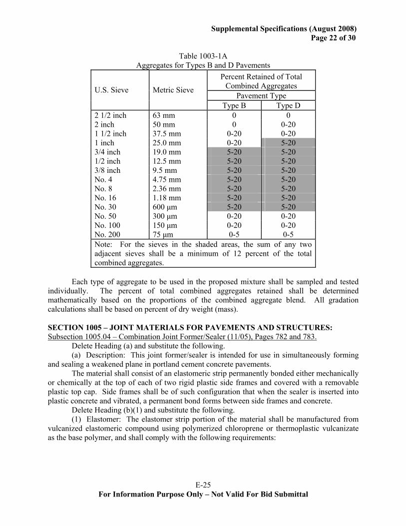
E-25 For Information Purpose Only – Not Valid For Bid Submittal
Supplemental Specifications (August 2008) Page 22 of 30
Table 1003-1A
Aggregates for Types B and D Pavements Percent Retained of Total
Combined Aggregates Pavement Type
U.S. Sieve Metric Sieve
Type B Type D 2 1/2 inch 63 mm 0 0 2 inch 50 mm 0 0-20 1 1/2 inch 37.5 mm 0-20 0-20 1 inch 25.0 mm 0-20 5-20 3/4 inch 19.0 mm 5-20 5-20 1/2 inch 12.5 mm 5-20 5-20 3/8 inch 9.5 mm 5-20 5-20 No. 4 4.75 mm 5-20 5-20 No. 8 2.36 mm 5-20 5-20 No. 16 1.18 mm 5-20 5-20 No. 30 600 μm 5-20 5-20 No. 50 300 μm 0-20 0-20 No. 100 150 μm 0-20 0-20 No. 200 75 μm 0-5 0-5 Note: For the sieves in the shaded areas, the sum of any two adjacent sieves shall be a minimum of 12 percent of the total combined aggregates.
Each type of aggregate to be used in the proposed mixture shall be sampled and tested
individually. The percent of total combined aggregates retained shall be determined mathematically based on the proportions of the combined aggregate blend. All gradation calculations shall be based on percent of dry weight (mass). SECTION 1005 – JOINT MATERIALS FOR PAVEMENTS AND STRUCTURES: Subsection 1005.04 – Combination Joint Former/Sealer (11/05), Pages 782 and 783.
Delete Heading (a) and substitute the following. (a) Description: This joint former/sealer is intended for use in simultaneously forming
and sealing a weakened plane in portland cement concrete pavements. The material shall consist of an elastomeric strip permanently bonded either mechanically
or chemically at the top of each of two rigid plastic side frames and covered with a removable plastic top cap. Side frames shall be of such configuration that when the sealer is inserted into plastic concrete and vibrated, a permanent bond forms between side frames and concrete.
Delete Heading (b)(1) and substitute the following. (1) Elastomer: The elastomer strip portion of the material shall be manufactured from
vulcanized elastomeric compound using polymerized chloroprene or thermoplastic vulcanizate as the base polymer, and shall comply with the following requirements:
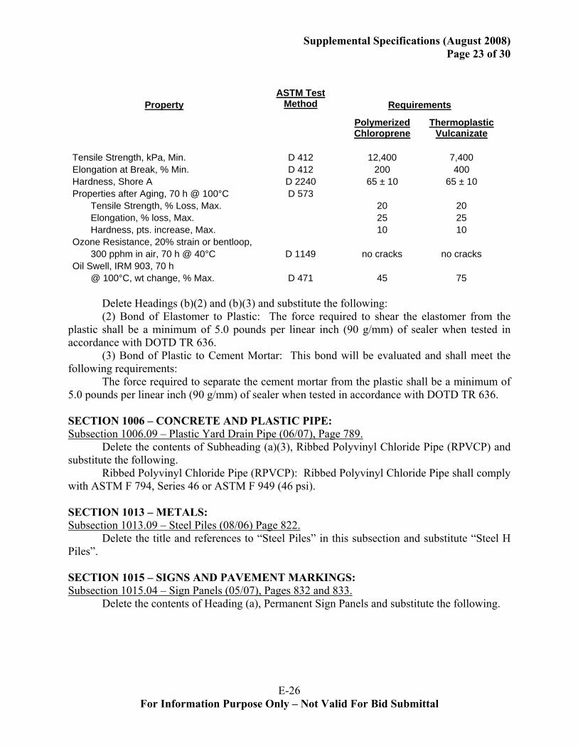
E-26 For Information Purpose Only – Not Valid For Bid Submittal
Supplemental Specifications (August 2008) Page 23 of 30
PropertyASTM Test
Method Requirements
Polymerized Chloroprene
Thermoplastic Vulcanizate
Tensile Strength, kPa, Min. D 412 12,400 7,400 Elongation at Break, % Min. D 412 200 400 Hardness, Shore A D 2240 65 ± 10 65 ± 10 Properties after Aging, 70 h @ 100°C D 573 Tensile Strength, % Loss, Max. 20 20 Elongation, % loss, Max. 25 25 Hardness, pts. increase, Max. 10 10 Ozone Resistance, 20% strain or bentloop, 300 pphm in air, 70 h @ 40°C D 1149 no cracks no cracks Oil Swell, IRM 903, 70 h @ 100°C, wt change, % Max. D 471 45 75
Delete Headings (b)(2) and (b)(3) and substitute the following: (2) Bond of Elastomer to Plastic: The force required to shear the elastomer from the
plastic shall be a minimum of 5.0 pounds per linear inch (90 g/mm) of sealer when tested in accordance with DOTD TR 636.
(3) Bond of Plastic to Cement Mortar: This bond will be evaluated and shall meet the following requirements:
The force required to separate the cement mortar from the plastic shall be a minimum of 5.0 pounds per linear inch (90 g/mm) of sealer when tested in accordance with DOTD TR 636. SECTION 1006 – CONCRETE AND PLASTIC PIPE: Subsection 1006.09 – Plastic Yard Drain Pipe (06/07), Page 789.
Delete the contents of Subheading (a)(3), Ribbed Polyvinyl Chloride Pipe (RPVCP) and substitute the following.
Ribbed Polyvinyl Chloride Pipe (RPVCP): Ribbed Polyvinyl Chloride Pipe shall comply with ASTM F 794, Series 46 or ASTM F 949 (46 psi). SECTION 1013 – METALS: Subsection 1013.09 – Steel Piles (08/06) Page 822.
Delete the title and references to “Steel Piles” in this subsection and substitute “Steel H Piles”. SECTION 1015 – SIGNS AND PAVEMENT MARKINGS: Subsection 1015.04 – Sign Panels (05/07), Pages 832 and 833.
Delete the contents of Heading (a), Permanent Sign Panels and substitute the following.
E-27 For Information Purpose Only – Not Valid For Bid Submittal
Supplemental Specifications (August 2008) Page 24 of 30
(a) Permanent Sign Panels: Flat panels shall be aluminum sheets or plates complying
with ASTM B 209, Alloy 6061-T6 or Alloy 5052-H38. Extruded aluminum panels shall comply with ASTM B 221 (ASTM B 221M), Alloy 6063-T6 and after fabrication, have a flatness equal to or less than 0.031 inch per foot of length and 0.004 inch per inch of width. Subsection 1015.05 - Reflective Sheeting (04/08), Pages 833 – 838. Delete the contents of this subsection and substitute the following. 1015.05 REFLECTIVE SHEETING. (a) Permanent and Temporary Standard Sheeting: Reflective sheeting shall be one of the following standard types as specified on the plans and complying with ASTM D 4956 except as modified herein. Permanent warning, regulatory, guide and supplemental guide sign sheeting shall meet the requirements of ASTM D 4956 Type X. Reflective sheeting for temporary signs and devices shall meet the requirements of ASTM D 4956 Type III except as noted in Subsection 1015.05(f). Reflective sheeting shall be an approved product listed in QPL 13. Type III - A high-intensity retroreflective sheeting that is typically encapsulated glass-bead
retroreflective material. Type VI - An elastomeric high-intensity retroreflective sheeting without adhesive. This
sheeting is typically a vinyl microprismatic retroreflective material. Type X - A super high-intensity retroreflective sheeting having highest retroreflectivity
characteristics at medium distances. This sheeting is typically an unmetalized microprismatic retroreflective element material.
(b) Fluorescent Pink Retroreflective Sheeting: Signs for temporary control of traffic through incident management areas shall be Type VI fluorescent pink retroreflective sheeting and shall comply with the MUTCD. Temporary traffic control signs for incident management shall be placed to notify motorists of upcoming incidents on the roadway, and shall be removed from public view once the incident has been managed. Physical properties shall comply with ASTM D 4956. Photometric properties shall be as follows. (1) Retroreflectivity: Minimum Coefficients of Retroreflection shall be as specified in Table 1015-1.
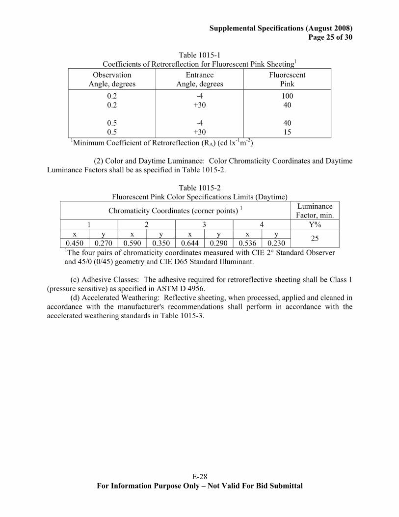
E-28 For Information Purpose Only – Not Valid For Bid Submittal
Supplemental Specifications (August 2008) Page 25 of 30
Table 1015-1
Coefficients of Retroreflection for Fluorescent Pink Sheeting1
Observation Angle, degrees
Entrance Angle, degrees
Fluorescent Pink
0.2 0.2
0.5 0.5
-4 +30
-4
+30
100 40
40 15
1Minimum Coefficient of Retroreflection (RA) (cd lx-1m-2) (2) Color and Daytime Luminance: Color Chromaticity Coordinates and Daytime Luminance Factors shall be as specified in Table 1015-2.
Table 1015-2 Fluorescent Pink Color Specifications Limits (Daytime)
Chromaticity Coordinates (corner points) 1 Luminance Factor, min.
1 2 3 4 Y% x y x y x y x y
0.450 0.270 0.590 0.350 0.644 0.290 0.536 0.230 25 1The four pairs of chromaticity coordinates measured with CIE 2° Standard Observer and 45/0 (0/45) geometry and CIE D65 Standard Illuminant.
(c) Adhesive Classes: The adhesive required for retroreflective sheeting shall be Class 1 (pressure sensitive) as specified in ASTM D 4956. (d) Accelerated Weathering: Reflective sheeting, when processed, applied and cleaned in accordance with the manufacturer's recommendations shall perform in accordance with the accelerated weathering standards in Table 1015-3.
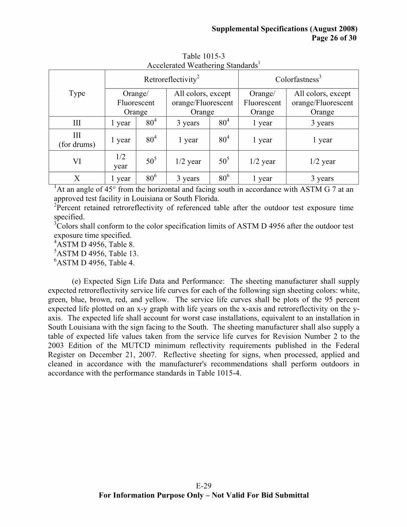
E-29 For Information Purpose Only – Not Valid For Bid Submittal
Supplemental Specifications (August 2008) Page 26 of 30
Table 1015-3
Accelerated Weathering Standards1
Retroreflectivity2 Colorfastness3
Type Orange/ Fluorescent
Orange
All colors, except orange/Fluorescent
Orange
Orange/ Fluorescent
Orange
All colors, except orange/Fluorescent
Orange III 1 year 804 3 years 804 1 year 3 years III
(for drums) 1 year 804 1 year 804 1 year 1 year
VI 1/2 year 505 1/2 year 505 1/2 year 1/2 year
X 1 year 806 3 years 806 1 year 3 years 1At an angle of 45° from the horizontal and facing south in accordance with ASTM G 7 at an approved test facility in Louisiana or South Florida. 2Percent retained retroreflectivity of referenced table after the outdoor test exposure time specified. 3Colors shall conform to the color specification limits of ASTM D 4956 after the outdoor test exposure time specified. 4ASTM D 4956, Table 8. 5ASTM D 4956, Table 13. 6ASTM D 4956, Table 4.
(e) Expected Sign Life Data and Performance: The sheeting manufacturer shall supply expected retroreflectivity service life curves for each of the following sign sheeting colors: white, green, blue, brown, red, and yellow. The service life curves shall be plots of the 95 percent expected life plotted on an x-y graph with life years on the x-axis and retroreflectivity on the y-axis. The expected life shall account for worst case installations, equivalent to an installation in South Louisiana with the sign facing to the South. The sheeting manufacturer shall also supply a table of expected life values taken from the service life curves for Revision Number 2 to the 2003 Edition of the MUTCD minimum reflectivity requirements published in the Federal Register on December 21, 2007. Reflective sheeting for signs, when processed, applied and cleaned in accordance with the manufacturer's recommendations shall perform outdoors in accordance with the performance standards in Table 1015-4.

E-30 For Information Purpose Only – Not Valid For Bid Submittal
Supplemental Specifications (August 2008) Page 27 of 30
Table 1015-4
Reflective Sheeting Performance Standards Retroreflectivity1 -- Durability2
Type Orange/ Fluorescent
Orange
All colors, except orange/Fluorescent
Orange
Colorfastness3
III 3 years 804 10 years 804 3 years X 3 years 805 7years 805 3 years
1Percent retained retroreflectivity of referenced table after installation and the field exposure time specified. 2All sheeting shall maintain its structural integrity, adhesion and functionality after installation and the field exposure time specified. 3All colors shall conform to the color specification limits of ASTM D 4956 after installation and the field exposure time specified. 4ASTM D4956, Table 8. 5ASTM D 4956, Table 4.
(f) Temporary Signs, Barricades, Channelizing Devices, Drums and Cones: Reflective sheeting for temporary signs, barricades and channelizing devices, shall meet the requirements of ASTM D 4956, Type III except that temporary warning construction signs used on the mainline of freeways and expressways shall be fluorescent orange and meet the requirements of ASTM D 4956, Type X. Reflective sheeting for vertical panels shall meet the requirements of ASTM D 4956, Type III. Reflective sheeting for drums shall be a minimum of 6 inches (150 mm) wide and shall meet the requirements of ASTM D 4956, Type III, and the Supplementary Requirement S2 for Reboundable Sheeting as specified in ASTM D 4956. Reflective sheeting for traffic cone collars shall meet the requirements of ASTM D 4956, Type III or Type VI. (g) Sheeting Guaranty. The contractor shall provide the Department with a guaranty from the sheeting manufacturer stating that if the retroreflective sheeting fails to comply with the performance requirements of this subsection, the sheeting manufacturer shall do the following:
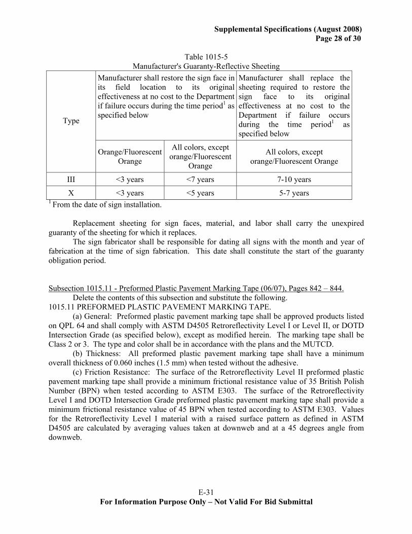
E-31 For Information Purpose Only – Not Valid For Bid Submittal
Supplemental Specifications (August 2008) Page 28 of 30
Table 1015-5
Manufacturer's Guaranty-Reflective Sheeting Manufacturer shall restore the sign face in its field location to its original effectiveness at no cost to the Department if failure occurs during the time period1 as specified below
Manufacturer shall replace the sheeting required to restore the sign face to its original effectiveness at no cost to the Department if failure occurs during the time period1 as specified below
Type
Orange/Fluorescent Orange
All colors, except orange/Fluorescent
Orange
All colors, except orange/Fluorescent Orange
III <3 years <7 years 7-10 years
X <3 years <5 years 5-7 years 1 From the date of sign installation. Replacement sheeting for sign faces, material, and labor shall carry the unexpired guaranty of the sheeting for which it replaces. The sign fabricator shall be responsible for dating all signs with the month and year of fabrication at the time of sign fabrication. This date shall constitute the start of the guaranty obligation period. Subsection 1015.11 - Preformed Plastic Pavement Marking Tape (06/07), Pages 842 – 844.
Delete the contents of this subsection and substitute the following. 1015.11 PREFORMED PLASTIC PAVEMENT MARKING TAPE.
(a) General: Preformed plastic pavement marking tape shall be approved products listed on QPL 64 and shall comply with ASTM D4505 Retroreflectivity Level I or Level II, or DOTD Intersection Grade (as specified below), except as modified herein. The marking tape shall be Class 2 or 3. The type and color shall be in accordance with the plans and the MUTCD.
(b) Thickness: All preformed plastic pavement marking tape shall have a minimum overall thickness of 0.060 inches (1.5 mm) when tested without the adhesive.
(c) Friction Resistance: The surface of the Retroreflectivity Level II preformed plastic pavement marking tape shall provide a minimum frictional resistance value of 35 British Polish Number (BPN) when tested according to ASTM E303. The surface of the Retroreflectivity Level I and DOTD Intersection Grade preformed plastic pavement marking tape shall provide a minimum frictional resistance value of 45 BPN when tested according to ASTM E303. Values for the Retroreflectivity Level I material with a raised surface pattern as defined in ASTM D4505 are calculated by averaging values taken at downweb and at a 45 degrees angle from downweb.
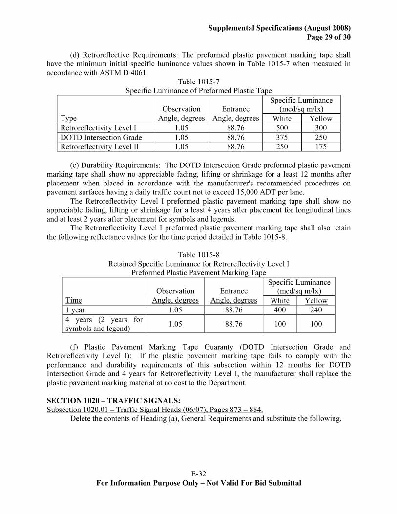
E-32 For Information Purpose Only – Not Valid For Bid Submittal
Supplemental Specifications (August 2008) Page 29 of 30
(d) Retroreflective Requirements: The preformed plastic pavement marking tape shall
have the minimum initial specific luminance values shown in Table 1015-7 when measured in accordance with ASTM D 4061.
Table 1015-7 Specific Luminance of Preformed Plastic Tape
Specific Luminance (mcd/sq m/lx)
Type
Observation
Angle, degrees
Entrance
Angle, degrees White Yellow Retroreflectivity Level I 1.05 88.76 500 300 DOTD Intersection Grade 1.05 88.76 375 250 Retroreflectivity Level II 1.05 88.76 250 175
(e) Durability Requirements: The DOTD Intersection Grade preformed plastic pavement
marking tape shall show no appreciable fading, lifting or shrinkage for a least 12 months after placement when placed in accordance with the manufacturer's recommended procedures on pavement surfaces having a daily traffic count not to exceed 15,000 ADT per lane.
The Retroreflectivity Level I preformed plastic pavement marking tape shall show no appreciable fading, lifting or shrinkage for a least 4 years after placement for longitudinal lines and at least 2 years after placement for symbols and legends.
The Retroreflectivity Level I preformed plastic pavement marking tape shall also retain the following reflectance values for the time period detailed in Table 1015-8.
Table 1015-8 Retained Specific Luminance for Retroreflectivity Level I
Preformed Plastic Pavement Marking Tape Specific Luminance
(mcd/sq m/lx) Time
Observation
Angle, degrees
Entrance
Angle, degrees White Yellow1 year 1.05 88.76 400 240 4 years (2 years for symbols and legend) 1.05 88.76 100 100
(f) Plastic Pavement Marking Tape Guaranty (DOTD Intersection Grade and
Retroreflectivity Level I): If the plastic pavement marking tape fails to comply with the performance and durability requirements of this subsection within 12 months for DOTD Intersection Grade and 4 years for Retroreflectivity Level I, the manufacturer shall replace the plastic pavement marking material at no cost to the Department. SECTION 1020 – TRAFFIC SIGNALS: Subsection 1020.01 – Traffic Signal Heads (06/07), Pages 873 – 884.
Delete the contents of Heading (a), General Requirements and substitute the following.
E-33 For Information Purpose Only – Not Valid For Bid Submittal
Supplemental Specifications (August 2008) Page 30 of 30
(a) General Requirements: Traffic signal sections, beacon sections and pedestrian signal
sections shall be of the adjustable type. Materials and construction of each section shall be the same.
Signals shall be constructed for either 8 or 12-inch (200 mm or 300 mm) lens in accordance with the plans. Signal sections shall have three to five sections per face and beacon sections have only one section per face. Signal sections and associated brackets shall be finished inside and out with two coats of high grade dark olive green enamel, color number 14056 according to Federal Standard No. 595b with each coat independently baked. Visors shall be coated green on the outside and black on the inside. Edges shall be deburred and smooth with no sharp edges. Subsection 1020.04 – Poles for Traffic Signal Systems (06/07), Pages 890 – 894.
Delete the sixth paragraph of Heading (a), Pedestal Support Signal Poles, and substitute the following.
Pedestals shall be finished with at least one coat of rustproofing primer, applied to a clean surface and one coat of dark olive green enamel, color number 14056 according to Federal Standard No. 595b.
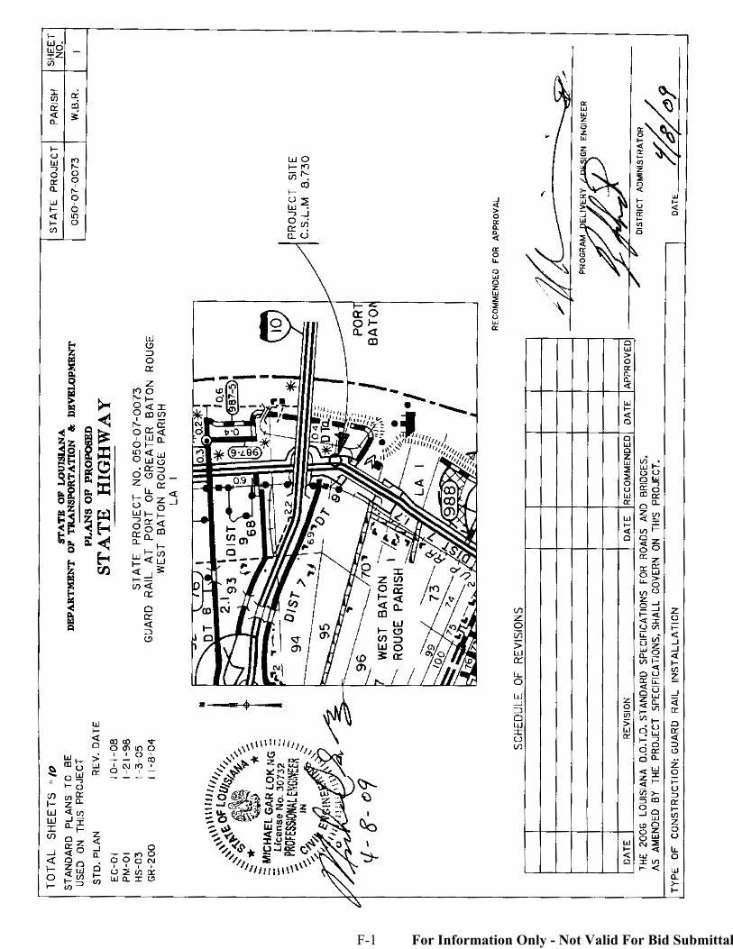
F-1 For Information Only - Not Valid For Bid Submittal
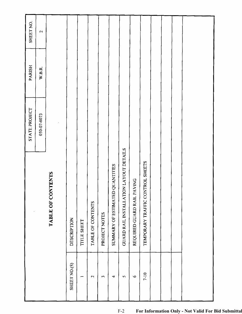
F-2 For Information Only - Not Valid For Bid Submittal
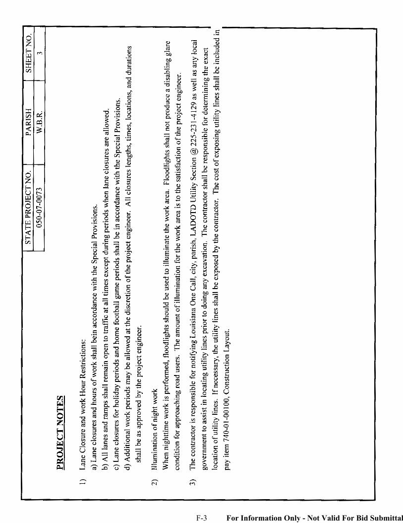
F-3 For Information Only - Not Valid For Bid Submittal
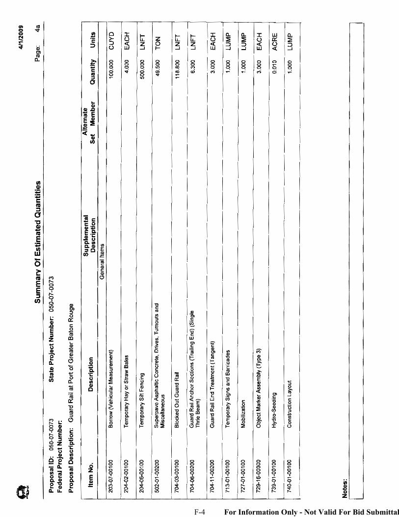
F-4 For Information Only - Not Valid For Bid Submittal

F-5 For Information Only - Not Valid For Bid Submittal
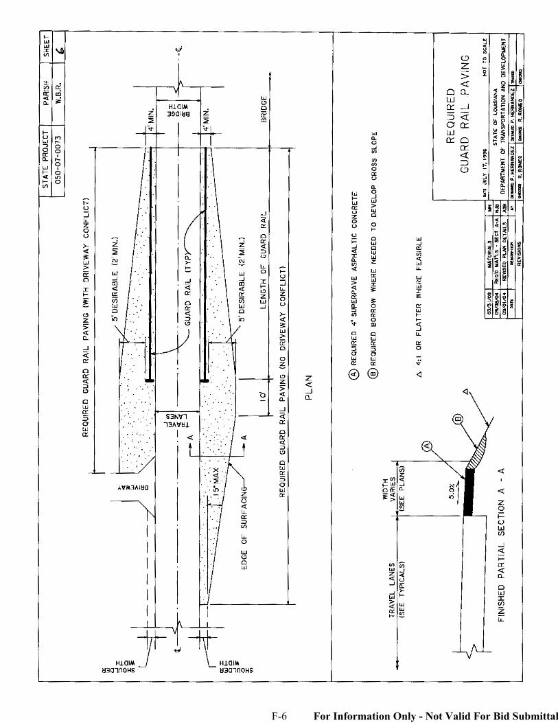
F-6 For Information Only - Not Valid For Bid Submittal
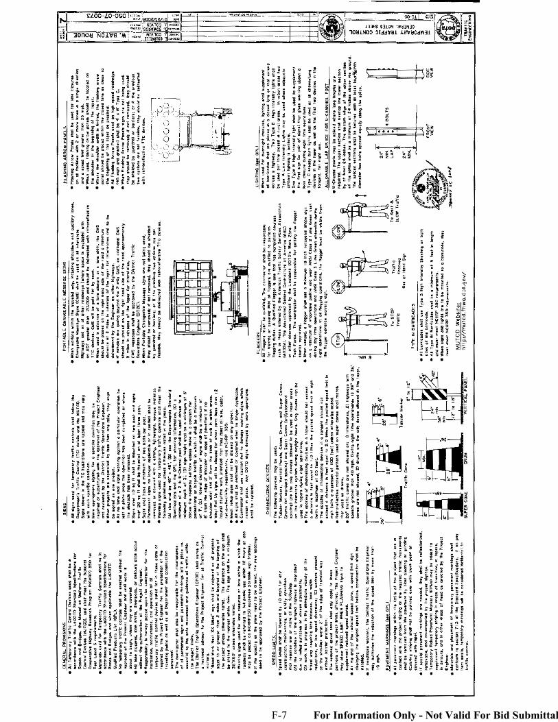
F-7 For Information Only - Not Valid For Bid Submittal
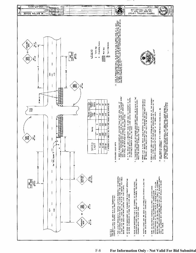
F-8 For Information Only - Not Valid For Bid Submittal
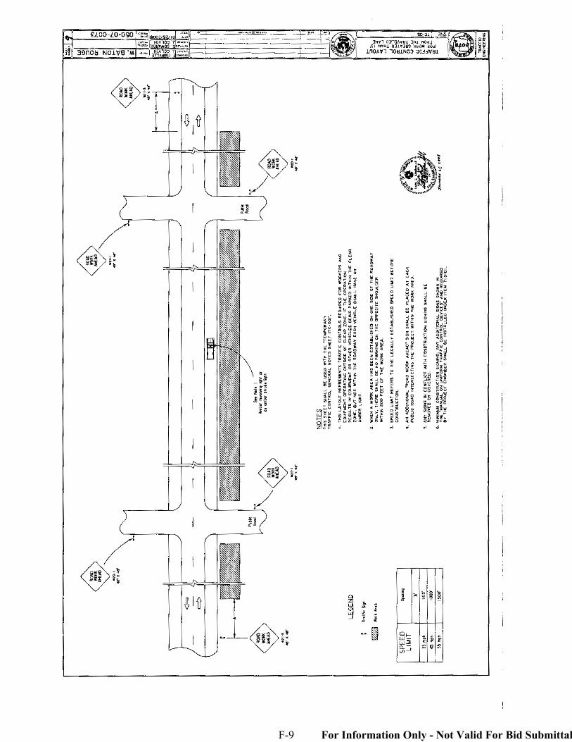
F-9 For Information Only - Not Valid For Bid Submittal
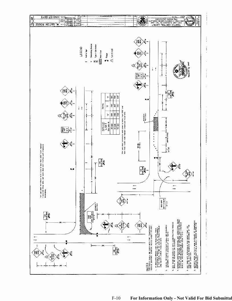
F-10 For Information Only - Not Valid For Bid Submittal
For Information Purpose Only – Not Valid For Bid Submittal
G-1
STATE OF LOUISIANA DEPARTMENT OF TRANSPORTATION AND
DEVELOPMENT
CONSTRUCTION PROPOSAL
RETURNABLES FOR
STATE PROJECT NO. 050-07-0073
GUARD RAIL AT PORT OF GREATER BATON ROUGE ROUTE LA 1
WEST BATON ROUGE PARISH
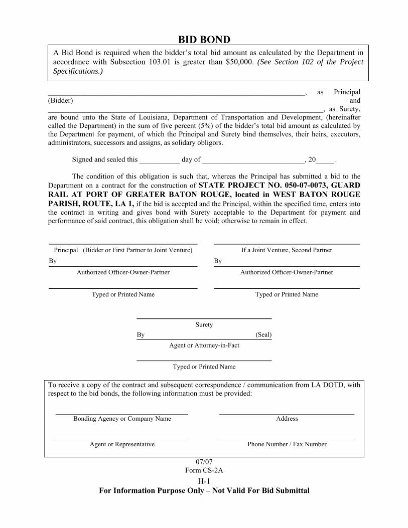
H-1 For Information Purpose Only – Not Valid For Bid Submittal
BID BOND
A Bid Bond is required when the bidder’s total bid amount as calculated by the Department in accordance with Subsection 103.01 is greater than $50,000. (See Section 102 of the Project Specifications.)
______________________________________________________________________, as Principal (Bidder) and ___________________________________________________________________________, as Surety, are bound unto the State of Louisiana, Department of Transportation and Development, (hereinafter called the Department) in the sum of five percent (5%) of the bidder’s total bid amount as calculated by the Department for payment, of which the Principal and Surety bind themselves, their heirs, executors, administrators, successors and assigns, as solidary obligors.
Signed and sealed this ___________ day of ____________________________, 20_____.
The condition of this obligation is such that, whereas the Principal has submitted a bid to the Department on a contract for the construction of STATE PROJECT NO. 050-07-0073, GUARD RAIL AT PORT OF GREATER BATON ROUGE, located in WEST BATON ROUGE PARISH, ROUTE, LA 1, if the bid is accepted and the Principal, within the specified time, enters into the contract in writing and gives bond with Surety acceptable to the Department for payment and performance of said contract, this obligation shall be void; otherwise to remain in effect.
Principal (Bidder or First Partner to Joint Venture)
If a Joint Venture, Second Partner
By
By
Authorized Officer-Owner-Partner
Authorized Officer-Owner-Partner
Typed or Printed Name
Typed or Printed Name
Surety By (Seal)
Agent or Attorney-in-Fact
Typed or Printed Name
To receive a copy of the contract and subsequent correspondence / communication from LA DOTD, with respect to the bid bonds, the following information must be provided:
Bonding Agency or Company Name Address
Agent or Representative Phone Number / Fax Number
07/07
Form CS-2A
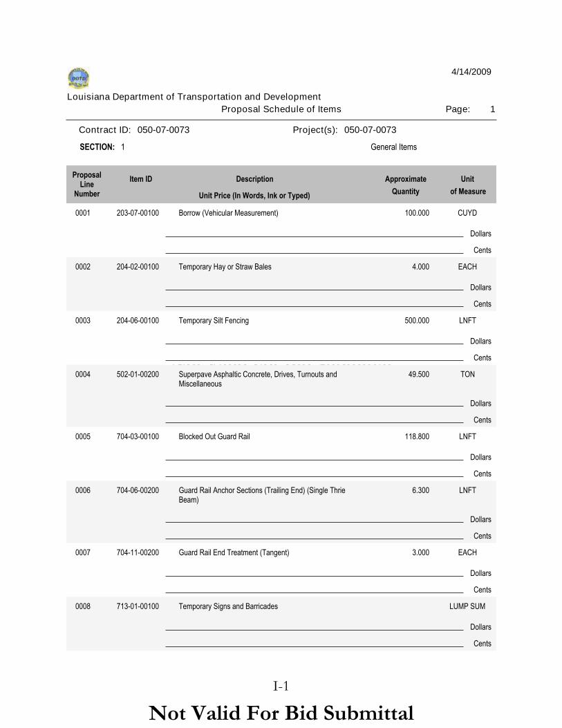
Not Valid For Bid Submittal
1Proposal Schedule of Items Page:Louisiana Department of Transportation and Development
4/14/2009
Contract ID: 050-07-0073 Project(s): 050-07-0073
1 General ItemsSECTION:
DescriptionItem IDProposalLine
Number
Unit
of Measure
Approximate
QuantityUnit Price (In Words, Ink or Typed)
Dollars
0001 203-07-00100 Borrow (Vehicular Measurement) CUYD100.000
Cents
Dollars
0002 204-02-00100 Temporary Hay or Straw Bales EACH4.000
Cents
Dollars
0003 204-06-00100 Temporary Silt Fencing LNFT500.000
Cents
Dollars
0004 502-01-00200 Superpave Asphaltic Concrete, Drives, Turnouts and Miscellaneous
TON49.500
Cents
Dollars
0005 704-03-00100 Blocked Out Guard Rail LNFT118.800
Cents
Dollars
0006 704-06-00200 Guard Rail Anchor Sections (Trailing End) (Single Thrie Beam)
LNFT6.300
Cents
Dollars
0007 704-11-00200 Guard Rail End Treatment (Tangent) EACH3.000
Cents
Dollars
0008 713-01-00100 Temporary Signs and Barricades
Cents
LUMP SUM
Not Valid For Bid SubmittalI-1
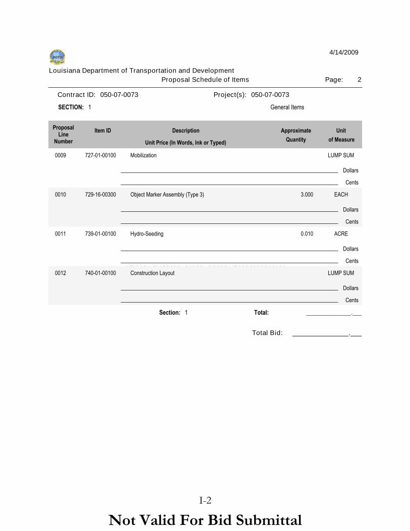
Not Valid For Bid Submittal
2Proposal Schedule of Items Page:Louisiana Department of Transportation and Development
4/14/2009
Contract ID: 050-07-0073 Project(s): 050-07-0073
1 General ItemsSECTION:
DescriptionItem IDProposalLine
Number
Unit
of Measure
Approximate
QuantityUnit Price (In Words, Ink or Typed)
Dollars
0009 727-01-00100 Mobilization
Cents
LUMP SUM
Dollars
0010 729-16-00300 Object Marker Assembly (Type 3) EACH3.000
Cents
Dollars
0011 739-01-00100 Hydro-Seeding ACRE0.010
Cents
Dollars
0012 740-01-00100 Construction Layout
Cents
LUMP SUM
Section: 1 _______________.___Total:
Total Bid: _______________.___
Not Valid For Bid SubmittalI-2
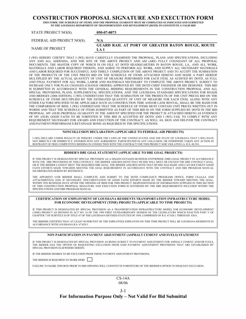
For Information Purpose Only – Not Valid For Bid Submittal
J-1
CONSTRUCTION PROPOSAL SIGNATURE AND EXECUTION FORM THIS FORM, THE SCHEDULE OF ITEMS, AND THE PROPOSAL GUARANTY MUST BE COMPLETED AS INDICATED AND SUBMITTED
TO THE LOUISIANA DEPARTMENT O TRANSPORTATION AND DEVELOPMENT (DOTD) TO CONSTITUTE A VALID BID F
STATE PROJECT NO(S). 050-07-0073 FEDERAL AID PROJECT NO(S).
N/A
NAME OF PROJECT
GUARD RAIL AT PORT OF GREATER BATON ROUGE, ROUTE LA 1
I (WE) HEREBY CERTIFY THAT I (WE) HAVE CAREFULLY EXAMINED THE PROPOSAL, PLANS AND SPECIFICATIONS, INCLUDING ANY AND ALL ADDENDA, AND THE SITE OF THE ABOVE PROJECT AND AM (ARE) FULLY COGNIZANT OF ALL PROPOSAL DOCUMENTS, THE MASTER COPY OF WHICH IS ON FILE AT DOTD HEADQUARTERS IN BATON ROUGE, LA., AND ALL WORK, MATERIALS AND LABOR REQUIRED THEREIN, AND AGREE TO PERFORM ALL WORK, AND SUPPLY ALL NECESSARY MATERIALS AND LABOR REQUIRED FOR SUCCESSFUL AND TIMELY COMPLETION OF THE ABOVE PROJECT AND TO ACCEPT THE SUMMATION OF THE PRODUCTS OF THE UNIT PRICES BID ON THE SCHEDULE OF ITEMS ATTACHED HERETO AND MADE A PART HEREOF MULTIPLIED BY THE ACTUAL QUANTITY OF UNIT OF MEASURE PERFORMED FOR EACH ITEM, AS AUDITED BY DOTD, AS FULL AND FINAL PAYMENT FOR ALL WORK, LABOR AND MATERIALS NECESSARY TO COMPLETE THE ABOVE PROJECT, SUBJECT TO INCREASE ONLY FOR PLAN CHANGES (CHANGE ORDERS) APPROVED BY THE DOTD CHIEF ENGINEER OR HIS DESIGNEE. THIS BID IS SUBMITTED IN ACCORDANCE WITH THE GENERAL BIDDING REQUIREMENTS IN THE CONSTRUCTION PROPOSAL AND ALL SPECIAL PROVISIONS, PLANS, SUPPLEMENTAL SPECIFICATIONS, AND THE LOUISIANA STANDARD SPECIFICATIONS FOR ROADS AND BRIDGES (2006 EDITION). I (WE) UNDERSTAND THAT THE SUMMATION OF THE PRODUCTS OF THE UNIT PRICES BID ON THE SCHEDULE OF ITEMS MULTIPLIED BY THE ESTIMATED QUANTITY OF UNIT OF MEASURE FOR EACH ITEM, ALONG WITH ANY OTHER FACTORS SPECIFIED TO BE APPLICABLE SUCH AS CONSTRUCTION TIME AND/OR LANE RENTAL, SHALL BE THE BASIS FOR THE COMPARISON OF BIDS. I (WE) UNDERSTAND THAT THE SCHEDULE OF ITEMS MUST CONTAIN UNIT PRICES WRITTEN OUT IN WORDS AND THAT THE SCHEDULE OF ITEMS SUBMITTED AS PART OF THIS BID IS ON THE FORM SUPPLIED BY DOTD IN THE BID PROPOSAL. MY (OUR) PROPOSAL GUARANTY IN THE AMOUNT SPECIFIED FOR THE PROJECT IS ATTACHED HERETO AS EVIDENCE OF MY (OUR) GOOD FAITH TO BE FORFEITED IF THIS BID IS ACCEPTED BY DOTD AND I (WE) FAIL TO COMPLY WITH ANY REQUIREMENT NECESSARY FOR AWARD AND EXECUTION OF THE CONTRACT, AS WELL AS, SIGN AND DELIVER THE CONTRACT AND PAYMENT/PERFORMANCE/RETAINAGE BOND AS REQUIRED IN THE SPECIFICATIONS.
NONCOLLUSION DECLARATION (APPLICABLE TO FEDERAL-AID PROJECTS) I (WE) DECLARE UNDER PENALTY OF PERJURY UNDER THE LAWS OF THE UNITED STATES AND THE STATE OF LOUISIANA THAT I (WE) HAVE NOT DIRECTLY OR INDIRECTLY, ENTERED INTO ANY AGREEMENT, PARTICIPATED IN ANY COLLUSION, OR OTHERWISE TAKEN ANY ACTION IN RESTRAINT OF FREE COMPETITIVE BIDDING IN CONNECTION WITH THE CONTRACT FOR THIS PROJECT NOR VIOLATED LA. R.S. 48:254.
BIDDER'S DBE GOAL STATEMENT (APPLICABLE TO DBE GOAL PROJECTS) IF THIS PROJECT IS DESIGNATED BY SPECIAL PROVISION AS A DISADVANTAGED BUSINESS ENTERPRISE (DBE) GOAL PROJECT IN ACCORDANCE WITH THE DBE PROVISIONS OF THIS CONTRACT, THE BIDDER ASSURES DOTD THAT HE/SHE WILL MEET OR EXCEED THE DBE CONTRACT GOAL, OR IF THE BIDDER CANNOT MEET THE REQUIRED DBE GOAL, THE BIDDER ASSURES DOTD THAT HE/SHE HAS MADE AND CAN DOCUMENT GOOD FAITH EFFORTS MADE TOWARDS MEETING THE GOAL REQUIREMENT IN ACCORDANCE WITH THE CONTRACT AND DBE PROGRAM MANUAL INCORPORATED HEREIN BY REFERENCE. THE APPARENT LOW BIDDER SHALL COMPLETE AND SUBMIT TO THE DOTD COMPLIANCE PROGRAMS OFFICE, FORM CS-6AAA AND ATTACHMENT(S) AND, IF NECESSARY, DOCUMENTATION OF GOOD FAITH EFFORTS MADE BY THE BIDDER TOWARD MEETING THE GOAL, WITHIN TEN BUSINESS DAYS AFTER THE OPENING OF BIDS FOR THIS PROJECT. RESPONSIVENESS OF INFORMATION SUPPLIED IN THIS SECTION OF THIS CONSTRUCTION PROPOSAL SIGNATURE AND EXECUTION FORM IS GOVERNED BY THE DBE REQUIREMENTS INCLUDED WITHIN THE SPECIFICATIONS AND DBE PROGRAM MANUAL.
CERTIFICATION OF EMPLOYMENT OF LOUISIANA RESIDENTS TRANSPORTATION INFRASTRUCTURE MODEL FOR ECONOMIC DEVELOPMENT (TIME) PROJECTS (APPLICABLE TO TIME PROJECTS)
IF THIS PROJECT IS DESIGNATED BY SPECIAL PROVISION AS A TRANSPORTATION INFRASTRUCTURE MODEL FOR ECONOMIC DEVELOPMENT (TIME) PROJECT AS DEFINED IN ACT NO. 16 OF THE 1989 FIRST EXTRAORDINARY SESSION OF THE LEGISLATURE WHICH ENACTED PART V OF CHAPTER 7 OF SUBTITLE II OF TITLE 47 OF THE LOUISIANA REVISED STATUTES OF 1950, COMPRISED OF R.S. 47:820.1 THROUGH 820.6. THE BIDDER CERTIFIES THAT AT LEAST 80 PERCENT OF THE EMPLOYEES EMPLOYED ON THIS TIME PROJECT WILL BE LOUISIANA RESIDENTS IN ACCORDANCE WITH LOUISIANA R.S. 47:820.3.
NON PARTICIPATION IN PAYMENT ADJUSTMENT (ASPHALT CEMENT AND FUELS) STATEMENT
IF THIS PROJECT IS DESIGNATED BY SPECIAL PROVISION AS BEING SUBJECT TO PAYMENT ADJUSTMENT FOR ASPHALT CEMENT AND/OR FUELS, THE BIDDER HAS THE OPTION OF REQUESTING EXCLUSION FROM SAID PAYMENT ADJUSTMENT PROVISIONS THAT ARE ESTABLISHED BY SPECIAL PROVISION ELSEWHERE HEREIN. IF THE BIDDER DESIRES TO BE EXCLUDED FROM THESE PAYMENT ADJUSTMENT PROVISIONS, THE BIDDER IS REQUIRED TO MARK HERE FAILURE TO MARK THIS BOX PRIOR TO BID OPENING WILL CONSTITUTE FORFEITURE OF THE BIDDER'S OPTION TO REQUEST EXCLUSION.
CS-14A 08/06
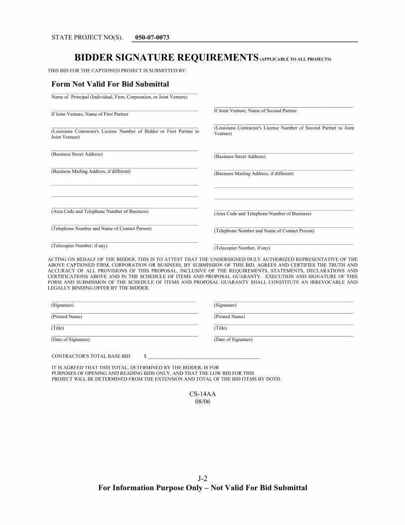
For Information Purpose Only – Not Valid For Bid Submittal
J-2
STATE PROJECT NO(S). 050-07-0073
BIDDER SIGNATURE REQUIREMENTS (APPLICABLE TO ALL PROJECTS)
THIS BID FOR THE CAPTIONED PROJECT IS SUBMITTED BY:
Form Not Valid For Bid Submittal ___________________________________________________________ Name of Principal (Individual, Firm, Corporation, or Joint Venture) ___________________________________________________________ If Joint Venture, Name of First Partner ___________________________________________________________ (Louisiana Contractor's License Number of Bidder or First Partner to Joint Venture) ___________________________________________________________ (Business Street Address) ___________________________________________________________ (Business Mailing Address, if different) ___________________________________________________________ ___________________________________________________________ ___________________________________________________________ (Area Code and Telephone Number of Business) ___________________________________________________________ (Telephone Number and Name of Contact Person) _______________________ ___________________________________ _(Telecopier Number, if any)
________________________________________________________ If Joint Venture, Name of Second Partner ________________________________________________________ (Louisiana Contractor's License Number of Second Partner to Joint Venture) ________________________________________________________ (Business Street Address) ________________________________________________________ (Business Mailing Address, if different) ________________________________________________________ ________________________________________________________ ________________________________________________________ (Area Code and Telephone Number of Business) ________________________________________________________ (Telephone Number and Name of Contact Person) _______________________ ________________________________ _(Telecopier Number, if any)
ACTING ON BEHALF OF THE BIDDER, THIS IS TO ATTEST THAT THE UNDERSIGNED DULY AUTHORIZED REPRESENTATIVE OF THE ABOVE CAPTIONED FIRM, CORPORATION OR BUSINESS, BY SUBMISSION OF THIS BID, AGREES AND CERTIFIES THE TRUTH AND ACCURACY OF ALL PROVISIONS OF THIS PROPOSAL, INCLUSIVE OF THE REQUIREMENTS, STATEMENTS, DECLARATIONS AND CERTIFICATIONS ABOVE AND IN THE SCHEDULE OF ITEMS AND PROPOSAL GUARANTY. EXECUTION AND SIGNATURE OF THIS FORM AND SUBMISSION OF THE SCHEDULE OF ITEMS AND PROPOSAL GUARANTY SHALL CONSTITUTE AN IRREVOCABLE AND LEGALLY BINDING OFFER BY THE BIDDER.
__________________________________________________________ (Signature) ___________________________________________________________ (Printed Name) ___________________________________________________________ (Title) ________________ _________________________________________ __(Date of Signature)
________________________________________________________ (Signature) ________________________________________________________ (Printed Name) ________________________________________________________ (Title) ________________ ______________________________________ __(Date of Signature)
CONTRACTOR'S TOTAL BASE BID $ _____________________________________________ IT IS AGREED THAT THIS TOTAL, DETERMINED BY THE BIDDER, IS FOR PURPOSES OF OPENING AND READING BIDS ONLY, AND THAT THE LOW BID FOR THIS PROJECT WILL BE DETERMINED FROM THE EXTENSION AND TOTAL OF THE BID ITEMS BY DOTD.
CS-14AA
08/06