
Lesson B2 RAINWATER HARVESTING - TUHHa · Exercises ... 4.2 Answers and Solutions ... Almost always...
32
EMWATER E-LEARNING COURSE PROJECT FUNDED BY THE EUROPEAN UNION LESSON C3: RAINWATER HARVESTING Lesson B2 RAINWATER HARVESTING Author: Franziska Meinzinger Institute of Wastewater Management Hamburg University of Technology Keywords Ground water recharge, Infiltration, Rainwater, Rainwater use, Runoff agriculture, Stormwater, Water harvesting,
Transcript of Lesson B2 RAINWATER HARVESTING - TUHHa · Exercises ... 4.2 Answers and Solutions ... Almost always...

EMWATER E-LEARNING COURSE PROJECT FUNDED BY THE EUROPEAN UNION
LESSON C3: RAINWATER HARVESTING
Lesson B2
RAINWATER HARVESTING
Author: Franziska Meinzinger
Institute of Wastewater Management Hamburg University of Technology
Keywords Ground water recharge, Infiltration, Rainwater, Rainwater use, Runoff agriculture, Stormwater, Water harvesting,
Page 2 of 32
EMWATER E-LEARNING COURSE PROJECT FUNDED BY THE EUROPEAN UNION
LESSON C3: RAINWATER HARVESTING
Table of content
Overview and summary of this lesson ....................................................................................... 3
1. General aspects ........................................................................................................................ 3
1.1 Rainwater management alternatives ................................................................................... 3
1.2 Data needs/storm runoff...................................................................................................... 5
1.3 Design flow.......................................................................................................................... 7
1.4 Water balance...................................................................................................................... 9
1.5 Stormwater pollutants ....................................................................................................... 10
2. Rainwater infiltration ........................................................................................................... 10
2.1 Preconditions for infiltration ............................................................................................ 11
2.2 Types of infiltration systems.............................................................................................. 12
2.3 Design of infiltration facilities .......................................................................................... 13
2.4 Special considerations and maintenance of infiltration facilities..................................... 15
3 Water harvesting techniques................................................................................................. 16
3.1 Benefits .............................................................................................................................. 16
3.2 Limitations......................................................................................................................... 17
3.3 History............................................................................................................................... 17
3.4 Harvesting methods........................................................................................................... 18
3.5 Water storage .................................................................................................................... 21
3.6 Design criteria................................................................................................................... 22 3.6.1 Runoff agriculture ...................................................................................................... 22 3.6.2 Storage tanks .............................................................................................................. 22
3.7 Traditional water harvesting techniques in Tunisia ......................................................... 24 3.7.1 Meskats....................................................................................................................... 24 3.7.2 Mgouds....................................................................................................................... 24 3.7.3 Jessour ........................................................................................................................ 26 3.7.4 Cisterns....................................................................................................................... 28
3.7.4.1 Different types of cisterns ................................................................................... 29
4. Exercises ................................................................................................................................. 30
4.1 Quetions ............................................................................................................................ 30
4.2 Answers and Solutions ...................................................................................................... 31

Page 3 of 32
EMWATER E-LEARNING COURSE PROJECT FUNDED BY THE EUROPEAN UNION
LESSON C3: RAINWATER HARVESTING
5. References .............................................................................................................................. 32
Overview and summary of this lesson The management of rainwater runoff represents an important aspect of water and wastewater management. Different methods exist in order to prevent flooding and erosion as well as to restore the natural hydrological water cycle. In contrast to off-site methods where the rainwater is collected, conveyed and discharged into waterways, rainwater infiltration and the use of rainwater by means of rainwater harvesting allow to address these issues and thus improve the water supply. This lesson covers some of the basic principles which are essential for the design of rainwater facilities. Then, rainwater infiltration techniques and their design are illustrated. The third part of this lesson introduces the concept and techniques of rainwater harvesting, which aims at storing stormwater runoff for the use in agriculture or domestic purposes. This lesson is rounded off with with the presentation of several Tunisian water harvesting techniques as they are applied in semi-arid and arid regions.
1. General aspects 1.1 Rainwater management alternatives Stormwater management techniques have to be designed specifically for the types of effect that are wanted to be brought about. In general, following measures for management of rainwater are commonly used (Ferguson, 1998): Use of rainwater / rainwater harvesting: Water harvesting is the direct capturing and use of runoff on-site. This can mean maintaining the water level in permanent ponds and wetlands or supplying water for irrigation and domestic purposes. For this the runoff either is stored and trickles away directly where the plants grow (runoff agriculture) or it is stored in tanks and reservoirs for later use.
Figure 1: Water Harvesting (Source: Ferguson, 1998)

Page 4 of 32
EMWATER E-LEARNING COURSE PROJECT FUNDED BY THE EUROPEAN UNION
LESSON C3: RAINWATER HARVESTING
Infiltration of rainwater: Infiltration is the soaking of rainwater into the ground via infiltration basins. Infiltration restores natural hydrologic processes and addresses in addition to flooding and erosion also water quality, groundwater and water supplies. Almost always the water quality is improved by the filtration and transformation processes in the soil.
Figure 2: Infiltration (Source: Ferguson, 1998) Conveyance: This is the moving of surface runoff from one place to another where it is eventually discharged to streams, lakes or bays. The facilities for conveyances are pipes and channels draining one into another. Please refer to lesson B1 for further information on the collection and conveyance of water.
Figure 3: Conveyance (Source: Ferguson, 1998)
Detention: Detention aims at slowing down the rate of flow of surface runoff. The basic facility is a basin or storage reservoir with an outlet that temporarily stores storm runoff. Storage reservoirs, which delay the passage of water during storm events, reduce the peak flow rate and therefore decrease the risk of downstream flooding and erosion. Nevertheless, the total volume of flow is still allowed to run downstream, stretched out over time. Detention is a quantitative modification of conveyance. On its own it is inherently unable to address water quality, groundwater replenishment or water supplies. When water is stored in properly designed ponds and wetlands, suspended particles can settle out and the rainwater can be "treated". This is commonly called extended detention.

Page 5 of 32
EMWATER E-LEARNING COURSE PROJECT FUNDED BY THE EUROPEAN UNION
LESSON C3: RAINWATER HARVESTING
Figure 4: Detention (Source: Ferguson, 1998) In this lesson the focus is on stormwater management techniques that are adapted to the natural hydrological cycle and that way help reduce the risk of flooding and erosion and improve the water availability. Therefore, stormwater infiltration (see section 3.2) as well as water harvesting techniques (See section 3.3) are illustrated in more detail.
1.2 Data needs/storm runoff 1.2.1 The design storm Rainfall usually varies significantly with respect to time and geographical location. A rainfall event is characterised by the duration and the intensity or total quantity of rainwater that is falling down. A design storm on which the design of a wastewater management facility is based is a particular combination of rainfall conditions for which runoff is estimated. The magnitude of a design storm may be expressed as a total quantity of precipitation such as millimetres of rainfall or as a short-term intensity such as millimetres per hour. Intensity can be calculated by dividing the total quantity of precipitation by the catchment area and the duration of the rainfall event. The recurrence interval is a way of expressing the probability that a storm of a given size or intensity may occur at a specific site. Recurrence interval, or frequency, is the average time between storms of a given magnitude. A 5-year storm is large enough that is has recurred, on the average, in only one of every 5 years in the local rainfall record. The probability of occurrence in any one year is the reciprocal of the recurrence interval. This means, the 5-year storm has a 20 percent chance of occurring in any one year, the 100-year storm has a 1 percent chance. When choosing the design storm for designing a stormwater facility one needs to balance the risks and the costs. The selection of a large, infrequent storm as design storm reduces the risk of failure of the facility but increases the costs for construction

Page 6 of 32
EMWATER E-LEARNING COURSE PROJECT FUNDED BY THE EUROPEAN UNION
LESSON C3: RAINWATER HARVESTING
and, thus, can make the facility uneconomical. For culverts and detention basins that drain local streets and prevent local drainage problems a 2- to 25-year recurrence interval is common. On the other hand, in extremely sensitive situations, where people's homes would be seriously damaged by flooding or their lives would be endangered, the most appropriate storm is the maximum probable storm, which can be larger than the 100-year storm. Usually local regulations specify the recurrence interval to be used. In Germany a 1-year recurrence interval and a duration of 15 minutes is used for the design of conveyance facilities, whereas infiltration systems are designed using a 5-year recurrence interval. Therefore, more intensive precipitation is used as a basis for the design of infiltration facilities in order to avoid the frequent failure of the systems.
Figure 5: Example of an intensity-duration-frequen cy curve
Duration of storm, minutes
recurrence interval
rainfall intensity, mm/h

Page 7 of 32
EMWATER E-LEARNING COURSE PROJECT FUNDED BY THE EUROPEAN UNION
LESSON C3: RAINWATER HARVESTING
Beside the recurrence interval, the duration of a storm is an important parameter. A storm that is short in duration can be very intense. As duration continues, high intensity is not maintained and therefore the average intensity decreases (See figure 5). In specifying a design storm, you must specify both recurrence interval and duration. Since every geographic location has a different rainfall pattern, local rainfall statistics can be useful to derive the absolute rainfall quantity of the design storm. 1.2.2 The drainage area The drainage area, or watershed, is the land area that drains to the point at which you estimate runoff. Any rainfall runoff model requires you to identify the drainage area and to specify its size, soil, and condition. A drainage area is identified by defining its boundaries on a map. For this, you need to first identify exactly the location where you are going to estimate runoff. Then you need to draw the boundary starting from the outlet and moving uphill on each side by the shortest (steepest) possible path perpendicular to the contour lines. This procedure finally results in the delineation of the watershed. Having drawn a drainage area's boundary correctly, you are in a position to estimate its size and to characterise its land use and soils to meet the needs of the rainfall runoff model you are using. 1.2.3 Time of concentration Runoff's travel time is one of the watershed characteristics that can strongly influence the rate of storm flow. If a given volume of runoff drains off a drainage area quickly, the peak rate of flow at the outlet is correspondingly high. Time of concentration is a special case of travel time. It is the maximum amount of time runoff from any point in a drainage area takes to flow to the outlet. Among a number of alternative paths that runoff could take from distant parts of a watershed, time of concentration is defined by the longest possible time, whether or not it involves the longest distance.
1.3 Design flow Before a rainwater management facility is designed, the storm runoff should be established, which refers to the volumes and rates of flow in individual rainfall events.The actual volume of runoff reaching a rainwater management facility depends on several factors. These include the design storm, the size of the catchment area, the degree of development in the basin (i.e., amount of impervious surface) as well as the

Page 8 of 32
EMWATER E-LEARNING COURSE PROJECT FUNDED BY THE EUROPEAN UNION
LESSON C3: RAINWATER HARVESTING
n
vna AAAA
ACACACACC
++++⋅++⋅+⋅+⋅
=...
...
321
332211
the soil surface. It is often called "direct runoff", because it results from surface flow and other immediate responses to precipitation. A runoff gauging station would provide a direct, factual way to observe flows from a site in its existing condition. However, only few sites have gauging stations so that some sort of estimate is necessary. The estimate should be based on data about the site and general knowledge of runoff processes (Urbonas & Stahre, 1993). The factors affecting the runoff such as plant cover are combined in the runoff coefficient, which indicates the percentage of the total water volume actually becoming runoff. The runoff coefficient is also dependent on the slope of the area. For steep slopes as well as for impermeable soils or sealed areas the runoff coefficient has higher values. Table 1 shows runoff coefficients which can be used as approximations Table 1: Runoff coefficients (Source: Ferguson & De bo, 1990)
Tye of surface or land use Runoff coefficient C Forest 0.1 - 0.3 Turf or meadow 0.1 - 0.4 Cultivated field 0.2 - 0.4 Bare earth 0.2 - 0.9 Pavement, concrete or asphalt 0.8 - 0.9 Flat residential, about 30% impervious 0.4 Flat residential, about 60% impervious 0.55 Sloping residential, about 50% impervious 0.65 Sloping, built-up, about 70% impervious 0.8 Flat commercial, about 90% impervious 0.8
For flat slopes or permeable soils use the lower values, for steep slopes or impermeable soils use the higher values.
If the catchment area consists of several areas with different land uses or surfaces, an average runoff coefficient is calculated according to the following formula: with:
A1 ... An: partial areas in square meters or hectares C1 ... Cn: runoff coefficients for the respecitve partial areas

Page 9 of 32
EMWATER E-LEARNING COURSE PROJECT FUNDED BY THE EUROPEAN UNION
LESSON C3: RAINWATER HARVESTING
Runoff calculation can be based on following formula: QT = C * IT * A with: QT: runoff rate for a T-year storm, in liters/second C: runoff coefficient, nondimensional IT: rainfall intensity for a T-year storm at a storm duration t,
in liters/(second*hectare) A: area of the catchment area, in hectares
The cumulative volume of rainwater over the storm duration can be calculated by multiplying the average runoff rate Q by the design storm duration t: VT = 3600 * QT * t with: VT: total runoff volume at time t for a T-year storm, in liters t: storm duration in hours
The total runoff volume for different design storms needs to be calculated by using different duration-intensity combinations for a given recurrence interval. Then, the largest runoff volume is used for the design of the rainwater management facility.
1.4 Water balance A water balance, like a storm runoff estimation, establishes volumes and rates of flow. Storm runoff and water balance estimations supplement each other as tools for evaluation and design. Storm runoff estimation is needed to protect against, control and utilise runoff during individual storm events. Water balance estimations show the effects of land use and stormwater control on the local ecosystem. The underlying principle of the water balance is the change-of-volume concept, expressed in the following equation applied to any component of a landscape during any given increment of time: storage = inflow - outflow Any difference between inflow and outflow must be accounted for by a change in the amount of water stored. The inflow can include precipitation, stream flow or artificial irrigation. The outflow can include evapotranspiration, direct runoff, base flow and additional outflows such as withdrawals for water supply. Figure 6 illustrates these different flows and the water balance concept. The water balance is a way to evaluate the aggregate effect of the hydrologic regime.

Page 10 of 32
EMWATER E-LEARNING COURSE PROJECT FUNDED BY THE EUROPEAN UNION
LESSON C3: RAINWATER HARVESTING
Figure 6: Water balance concept (Source: Ferguson, 1998)
1.5 Stormwater pollutants Pollution of rainwater is caused by atmospheric pollution (such as emissions from industries and transport) as well as pollutants that are taken up during surface runoff. Among other things paper, oil, remainders of metals and rubbers, organic matter from vegetation and excrements can accumulate in the surface runoff. The main sources of anthropogenic pollution of rainwater is traffic and waste. The constituents vary in their nature and concentration according to local conditions. Atmospheric rainwater is usually very pure and most contamination of the water occurs after contact with the catchment system. Rainwater from ground catchment systems is not recommended for drinking unless it is first boiled or treated. For the pretreatment of rainwater physical (such as sedimentation and filtration) and biological processes can be used. Biological treatment often occurs in biologically active soil filters or root zones. Please refer to the respective sections of this course for further information about physical and biological treatment processes.
2. Rainwater infiltration The use of infiltration facilities represents an attractive opportunity to contribute to the recharge of groundwater and thus to minimise the interference of the natural water cycle. Stormwater infiltration returns surface flows to the subsurface and, thus, never aggravates flooding downstream. Additionally, a significant portion of the pollutant load of stormwater, which is normally directed to the receiving water, can be removed. If the

Page 11 of 32
EMWATER E-LEARNING COURSE PROJECT FUNDED BY THE EUROPEAN UNION
LESSON C3: RAINWATER HARVESTING
soil through which water infiltrates contains any degree of clay or humus, the soil is a powerful filter that protects aquifers from contamination. Some advantages of local rainwater infiltration are:
• recharge of groundwater
• preservation and/or enhancement of natural vegetation
• reduction of pollution transported to the receiving waters
• reduction of downstream flow peaks
• reduction of basement flooding in combined sewer systems
• reduction in the settlement of the surface in areas of groundwater depletion
• smaller storm sewers at a lesser cost In some cases rainwater infiltration may have following negative impacts (Urbonas & Stahre, 1993):
• soils seal with time
• some infiltration facilities may not receive proper maintenance
• reliance on their operation may leave communities facing enormous capital costs in
the future, if these systems begin to fail
• groundwater level may rise and cause basement flooding or damage to building foundations
2.1 Preconditions for infiltration Regarding the site selection, a number of factors determine the suitability of a site for rainwater infiltration:
• Vegetative cover: Rainwater can be absorbed by plant roots and can be returned to the atmosphere through plant respiration. The soil-vegetation complex functions to a certain degree as a filter that reduces clogging of the surface pores of the soil.
• Soil type and conditions: Effective porosity and permeability are soil parameters that influence the infiltration process. Bedrock should not be within less than 1.2 meters of the infiltration surface.
• Groundwater conditions: Distance to groundwater and variation in groundwater levels are some of the information needed for planning infiltration facilities. It is recommended that the distance to groundwater is at least 1 meter.

Page 12 of 32
EMWATER E-LEARNING COURSE PROJECT FUNDED BY THE EUROPEAN UNION
LESSON C3: RAINWATER HARVESTING
2.2 Types of infiltration systems There are a number of possibilities for decentralised or on-site infiltration systems, which are described in the following section. It should be noted that often combinations of the different systems are used. 2.2.1 Infiltration beds Infiltration beds represent the simplest form of local infiltration. The rainwater is let run onto a vegetation-covered surface where it infiltrates. In areas with high groundwater table or fine-grained soils, infiltration can be very slow and may result in standing water. 2.2.2 Open ditches The use of open ditches and swales adjacent to streets, roads, highways, and small parking lots is a special case of surface infiltration. The infiltration capacity depends on factors such as the porosity of the soil and the suspended solids load in the stormwater, and it may not be possible to infiltrate all the runoff into the ground using only swales and ditches, when the catchment area is too large compared to the available infiltrating surface. Good vegetation growth in open ditches is essential, since the vegetation re-aerates the soil surfaces when they become clogged with fine sediments carried by the runoff. In addition to swales and ditches percolation trenches can be installed.
Figure 7: Swale
Figure 8 : Infiltration ditch (Source: Universität Trier)

Page 13 of 32
EMWATER E-LEARNING COURSE PROJECT FUNDED BY THE EUROPEAN UNION
LESSON C3: RAINWATER HARVESTING
2.2.3 Percolation basins A percolation basin is constructed by excavating a pit, filling it with gravel or crushed stone, and then backfilling over the top of the rock. The rock media provide the porosity for temporary storage of water so that it can then slowly percolate into the ground. Basins should not be submerged by groundwater, as this will hinder their proper function. In order to reduce the risk of clogging of the rocks by suspended particles, it is advantageous to filter the stormwater before it enters the rockfilled basin by passing either through a granular filter bed or a fine mesh geotextile material. The filter media needs to be removed and replaced from time to time. 2.2.4 Pipe trench A pipe trench is a special case of a percolation basin where the stormwater is stored not only in the rock media, but in the pipe itself. Clogging can also occur in the pipe trench, so that filtering of stormwater should be part of each pipe trench installation.
2.3 Design of infiltration facilities The design of infiltration facilities should be in such a way that the facility will contain the design inflow without overflowing. Generally, infiltration and percolation facilities will work best for small catchment areas and they should be designed conservatively, using low hydraulic loading rates. The design loading rates should be low enough to allow the water to drain away after a rainfall event. When a site has been judged to be an acceptable candidate for an infiltration basin (see above, 'Preconditions for infiltration'), the next step is to find the required surface area and storage volume for the facility. The size of the infiltration surface depends on the infiltration rate, which differs for different soil types and should be obtained from infiltration tests at each site. For the design of a percolation facility Darcy's Law is used for the estimation of the percolating water:
U = k * I with: U: flow velocity in meters per second k: hydraulic conductivity in meters per second I: hydraulic gradient in meters per meter
Page 14 of 32
EMWATER E-LEARNING COURSE PROJECT FUNDED BY THE EUROPEAN UNION
LESSON C3: RAINWATER HARVESTING
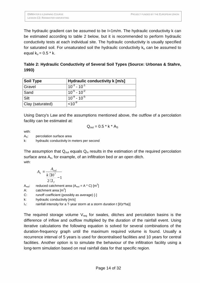
The hydraulic gradient can be assumed to be I=1m/m. The hydraulic conductivity k can be estimated according to table 2 below, but it is recommended to perform hydraulic conductivity tests at each individual site. The hydraulic conductivity is usually specified for saturated soil. For unsaturated soil the hydraulic conductivity ku can be assumed to equal ku = 0.5 * k. Table 2: Hydraulic Conductivity of Several Soil Typ es (Source: Urbonas & Stahre, 1993)
Soil Type Hydraulic conductivity k [m/s] Gravel 10-3 - 10-1 Sand 10-5 - 10-2 Silt 10-9 - 10-5 Clay (saturated) <10-9 Using Darcy's Law and the assumptions mentioned above, the outflow of a percolation facility can be estimated at:
Qout = 0.5 * k * AS with: AS: percolation surface area k: hydraulic conductivity in meters per second
The assumption that Qout equals Qin results in the estimation of the required percolation surface area As, for example, of an infiltration bed or an open ditch. with:
Ared: reduced catchment area (Ared = A * C) [m2] A: catchment area [m2] C: runoff coefficient (possibly as average) [-] k: hydraulic conductivity [m/s] IT: rainfall intensity for a T-year storm at a storm duration t [l/(s*ha)]
The required storage volume Vreq for swales, ditches and percolation basins is the difference of inflow and outflow multiplied by the duration of the rainfall event. Using iterative calculations the following equation is solved for several combinations of the duration-frequency graph until the maximum required volume is found. Usually a recurrence interval of 5 years is used for decentralised facilities and 10 years for central facilities. Another option is to simulate the behaviour of the infiltration facility using a long-term simulation based on real rainfall data for that specific region.
12
107
−⋅⋅
=
T
redS
I
k
AA

Page 15 of 32
EMWATER E-LEARNING COURSE PROJECT FUNDED BY THE EUROPEAN UNION
LESSON C3: RAINWATER HARVESTING
with: Vreq: required storage volume [m3] AS: percolation surface area, can be assumed to vary between 0.05 * Ared and 0.2 * Ared [m
2] Ared: reduced catchment area (Ared = A * C) [m2] k: hydraulic conductivity in saturated zone [m/s] IT: rainfall intensity for a T-year storm at a storm duration t [l/(s*ha)] t: duration of the rainfall event [min] fZ: safety factor (e.g. 1.2) Concerning the calculation of percolation basins and pipe trenches it has to be noticed that AS does not need to be included into the calculation of the catchment area, because the pipe surface is underground and does, therefore, not contribute to the catchment area.
2.4 Special considerations and maintenance of infiltration facilities Regular maintenance is needed to ensure proper operation of infiltration systems. In general, these systems do not have a full-time inspection. Therefore, proper installation inspection and quality control procedures will sometimes have to be provided by the community. In order to keep the infiltration surface porous, vegetation growing on the infiltration zone needs to be maintained. As the facility ages and the surface soils become clogged, the top soil layers may have to be removed, replaced, and re-vegetated to restore the infiltration capacity. Maintenance of percolation facilities is mainly related to keeping the inlet filter free from plugging. The filter fabric and sand layers need to be checked frequently and cleaned. After a couple of years it may become necessary to replace the rock media of the percolation facility, if the pores are filled by fine particles. Infiltration rates in a newly constructed facility will be less than anticipated. Also ageing facilities may fail and will have to be repaired or replaced. Therefore, downstream conveyance system may need to handle more runoff, which should be kept in mind when constructing these facilities. Clogging of infiltration systems is caused by fine eroded particles. Thus, it is very important to control erosion in the catchment area, for example, through the installation of splash pads at downspouts or the use of rock or paved rundowns.
( )( )[ ] ZSTSredreq
outinreq
ftkAIAAV
tQQV
⋅⋅⋅⋅⋅−⋅⋅+=
⋅−=−
∑∑605.010 7

Page 16 of 32
EMWATER E-LEARNING COURSE PROJECT FUNDED BY THE EUROPEAN UNION
LESSON C3: RAINWATER HARVESTING
The inflow of stormwater into the ground will affect the groundwater levels and water quality in the region. Therefore, this impact needs to be considered, for example, if rising groundwater levels are expected to be above basement floor elevations. Usually, the recharge of groundwater by nonindustrial stormwater has no serious impact on the water quality, so that the water can be used as drinking water supply. Nevertheless, there is the risk that toxic chemicals or other pollutants may enter the groundwater with the infiltrated stormwater (Urbanos & Stahre,1993).
3. Water harvesting techniques Generally the term “water harvesting” comprises many techniques that are used to supply rainwater collected from surfaces (roofs, ground surface, rock surface) for domestic or agricultural use. It can be defined as “... the process of concentrating rainfall as runoff from a larger catchment area to be used in a smaller target area” (Oweis et al.,1999, p.2). Water harvesting techniques represent methods to provide water for irrigation, watering domestic smallstock or domestic purposes from other sources than (permanent) streams, rivers and pumped groundwater. Usually a rainwater system consists of three main components: a catchment area, a storage reservoir and a delivery system. The target area can be the soil profile of the cultivated area or some kind of reservoir or tank. Water harvesting is particularly relevant to areas where rainfall is insufficient to balance evapotranspiration of crops and to sustain a good pasture growth.
3.1 Benefits Generally the low rainfall in arid and semi-arid areas is distributed with a high variability in space and time, which hinders profitable agriculture and creates instability in production. However, concentrating the scarce rainwater into smaller areas by means of water harvesting techniques allows economic agricultural production and can also improve drinking water supplies in arid regions. Surface water harvesting techniques that are well adapted to the ecological and social context have the potential to improve the productivity of arable and grazing land by increasing the yields and reducing the risk of crop failure. They are relatively cheap and can therefore be a viable alternative in regions where irrigation water from other sources is too costly. Water harvesting can reduce the use of groundwater, which is a valuable water source and needs energy for its exploitation. The collection of rainwater can even contribute to the recharge of groundwater tables (Prinz, 1999). Very often rainwater harvesting techniques help to

Page 17 of 32
EMWATER E-LEARNING COURSE PROJECT FUNDED BY THE EUROPEAN UNION
LESSON C3: RAINWATER HARVESTING
prevent floods and to control soil erosion. Thus the systems allow not only a suitable irrigation in regions with scarce water sources but also an improvement of the hydrological equilibrium and the soil quality (Alaya et al., 1993).
3.2 Limitations It should be paid attention to minimise side effects, since poorly designed and managed systems can lead to soil erosion, soil instability and local floods. Water harvesting techniques increase the water availability, yet the climatic variability can not be completely compensated. Years with extremely low precipitation still threaten the production, and torrential rainfalls can often lead to destructive runoff. Large storage tanks may be required in areas where the dry season is long. In addition, the rainwater may be contaminated, so that extra care should be taken when the collected rainwater is used as drinking water. The success of water harvesting projects is often based on farmer’s experience and their willingness to adopt and accept the techniques (Prinz, 1999).
3.3 History Water harvesting is almost 4000 years old: it began in the Bronze Age, when desert dwellers in the Middle East smoothed hillsides to increase rainwater runoff and built ditches to collect the water and convey it to lower lying fields. Archaeological findings and historical descriptions show that water harvesting played an important role in supporting a flourishing agriculture in many regions. A wide variety of hydraulic structures have been introduced during many centuries to make the land productive irrespective of its restrictive natural conditions. Presumably millions of hectares of land in dry areas, where rainfall is low and erratic in distribution, were once cultivated with water harvesting techniques, but many causes have brought a steady decline. Namely the preference of larger irrigation schemes and social changes like the migration of manpower are responsible for the common neglect of these techniques. But since water harvesting represents a sustainable method of providing non-costly water and improving the productivity of land that suffers from inadequate rainfall, the interest in these systems has increased during recent decades.

Page 18 of 32
EMWATER E-LEARNING COURSE PROJECT FUNDED BY THE EUROPEAN UNION
LESSON C3: RAINWATER HARVESTING
3.4 Harvesting methods Surface water harvesting requires runoff producing areas with sufficiently high runoff coefficients and runoff receiving areas, where the water is utilised. The differences between the different harvesting methods lie mainly in the size of the systems.
Figure 9 Examples of micro-catchment water harvesti ng (contour bench terrace, bunds, Negarim system) (Source: FAO, 1999) “Rainwater harvesting” is the collection and concentration of rainfall either from roofs and courtyards, from micro-catchments, or from macro-catchments. Water collected from paved, compacted or otherwise treated surfaces like rooftops is mainly used for domestic purposes and livestock watering. “Micro-catchment water harvesting” (see figure 9) stands for the collection of surface runoff from a relatively small catchment area (less than 1000 m2). The water is stored in the root zone of an adjacent infiltration basin, that is planted with a single tree or bush or with annual crops. “Medium-sized” or “macro-catchment water harvesting” (figure 10) is the collection of water in larger catchment areas (1000 m2 – 200 ha), that are located outside the cultivated areas. From there the runoff is conveyed to the cropping areas (Prinz, 1996).

Page 19 of 32
EMWATER E-LEARNING COURSE PROJECT FUNDED BY THE EUROPEAN UNION
LESSON C3: RAINWATER HARVESTING
Figure 10: Example of macro-catchment water harves ting (hillside conduit, photo: Klemm) “Floodwater harvesting” is also referred to as large catchment water harvesting with catchments being many square kilometres in size. It includes the harvesting of water within the streambeds of ephemeral or seasonal rivers (“wadis”) and the diversion of the wadi water. For this dams can be constructed within the riverbed, that block the water flow leading to an inundation of the valley bottom of the flood plain. Thus the water infiltrates and allows the use of the wetted area as cropping zone (See figure 15). “Floodwater diversion” (Figure 11) is the construction of dikes or other diversion structures forcing a part of the wadi water to leave its natural course and conveying it to nearby cropping areas. Since “floodwater harvesting systems” include a more complex structure of dams and distribution networks, relatively high technical input is required (Prinz, 1996).

Page 20 of 32
EMWATER E-LEARNING COURSE PROJECT FUNDED BY THE EUROPEAN UNION
LESSON C3: RAINWATER HARVESTING
Figure 11: Examples of floodwater diversion (Source : FAO, 1999)
Diversion dam
River bed
Cropping areas

Page 21 of 32
EMWATER E-LEARNING COURSE PROJECT FUNDED BY THE EUROPEAN UNION
LESSON C3: RAINWATER HARVESTING
3.5 Water storage Storage facilities allow the later use of runoff water as supplemental irrigation water. They can partly overcome the problem of the unreliability of rainfall. This also allows the prolongation of the cropping season or a second crop. The storage can be aboveground or underground. Surface storage, for example in ponds, has the disadvantage of evaporation losses as well as siltation and pollution. These drawbacks can be avoided by underground storage in cisterns, that can keep the water losses by evaporation and percolation minimal, if they are covered and have plastered walls. Siltation can be minimised by reducing erosion, or by installing a silt-trap through which the runoff passes before it flows into the storage tank. Storage facilities not only prevent the loss of runoff during periods of heavy rainfall but also play an important part in reducing floods and controlling soil erosion (Prinz & Wolfer, 1999). Storage reservoirs include various types of surface and sub-surface tanks, rock catchment dams, earth dams, and sub-surface or sand dams in sand rivers. Surface tanks can be made of ferrocement, bricks, reinforced concrete, metal, plastic, fibreglass and wood. Sub-surface tanks are usually made of ferrocement, concrete, brick and traditional clay linings. Furthermore, water harvesting dams can be built of soil, rock or sand.
Figure 12: Rainwater storage tank (Source: Gould & Nissen-Petersen, 1999)

Page 22 of 32
EMWATER E-LEARNING COURSE PROJECT FUNDED BY THE EUROPEAN UNION
LESSON C3: RAINWATER HARVESTING
3.6 Design criteria 3.6.1 Runoff agriculture The appropriate choice of a technique depends on the amount of rainfall and its distribution, soil type and depth, land topography and local socio-economic factors (Oweis et al., 1999). Loess and loess-like soils are ideally suited for rainwater harvesting because even after a small rainfall a crust is formed that promotes runoff. Slope affects the quantity and the quality of runoff. The most efficient water harvest is on small, gently sloping catchments (with a slope preferably between 1 % and 5 %). The ratio of the surface of the catchment area (runoff producing area or impluvium) to the surface of the cropping zone is expressed by the factor CCR (“catchment to cropping ratio”). In the course of time the respective ratios became apparent for the different systems according to the climatic conditions. The factor can also vary depending on the characteristics of the watershed. When planning a water harvesting system the proper establishment of the CCR is very important in order to avoid an insufficient water supply or damages to the systems as a result of an outsized catchment area (Alaya et al., 1993). The CCR is directly related to the mean annual precipitation quantity and the mean runoff coefficient of the region. It also depends on the water requirements of the crops. The knowledge of these three parameters is indispensable for applying rainwater harvesting systems on a serious technical foundation. The relation between CCR and the three factors is the following: CCR · C · P = WR – P or: CCR = (WR – P) / (C · P) With: CCR: area impluvium / area cropping zone [-] P: mean annual precipitation [mm] C: mean annual runoff coefficient [-] WR: water requirements of the crops [mm]
3.6.2 Storage tanks If the water harvesting system includes a storage tank, the tank needs to be sized correctly in order to give adequate storage capacity and at the same time minimize capital investment. The storage requirement will be determined by a number of interrelated factors such as the local rainfall data and weather patterns, catchment

Page 23 of 32
EMWATER E-LEARNING COURSE PROJECT FUNDED BY THE EUROPEAN UNION
LESSON C3: RAINWATER HARVESTING
area, runoff coefficient, user numbers and consumption rates. The calculation of the storage capcity can either be based on the actual demand or the possible supply of rainwater (Hartung, 2002). Demand side approach: storage requirement R = C * n * d with: C: Consumption per capita per day n: number of people d: longest average dry period
Supply side approach: annual available water W = A * C * R with: A: catchment/roof area C: runoff coefficient R: average annual rainfall
demand D = R as calculated above in the demand side approach The storage requirement can be derived as maximum difference between the cumulative harvested water and the cumulative demand. Storage tanks should be watertight with a solid, secure cover, a screened inlet, an overflow pipe and a covered manhole. The extraction system should be designed in such a way that the water quality is protected. The choice of a specific system depends on several factors such as for example: - space availability - option available locally - local traditions for water storage - cost - of purchasing new tank and of materials and labour for construction - materials and skills available locally - ground conditions - patterns of usage

Page 24 of 32
EMWATER E-LEARNING COURSE PROJECT FUNDED BY THE EUROPEAN UNION
LESSON C3: RAINWATER HARVESTING
3.7 Traditional water harvesting techniques in Tunisia The following section presents traditional water harvesting techniques as they are applied in Tunisia as examples for rainwater harvesting in semiarid and arid regions. 3.7.1 Meskats The meskat system is a very ancient water harvesting technique that was already known and wide spread in the Roman era. This technique, which is typical for gentle slopes and low hills, is mainly found in the so-called Tunisian Sahel region, where a semiarid to arid climate with mean annual rainfall of about 300 mm prevails. The technique is an example for micro-catchment water harvesting techniques with relatively small catchment sizes. It is based on a catchment area or impluvium called “meskat” and a cropping zone (“mangaâ” or “mankaâ”) (see figure 13). The impluvium, generally about 500 m2 in size, supplies additional water to a series of downstream plots, which are enclosed by small earth bunds (about 20 cm) and connected by spillways for discharging the excess water. In general the surface of the impluvium should be twice the cropping area, thus the catchment to cropping ratio (CCR) is 2:1 (Achouri, 1994). By breaking the runoff the meskat technique also contributes to the recharge of ground water as well as to the decrease of floods and water erosion.
Figure 13: Meskat system (Source: Prinz, 1996 and O ueasser ) 3.7.2 Mgouds This floodwater diversion technique is very common in the plains adjacent to great wadis in Central Tunisia. It is a channel system based on the diversion of floodwater from its natural course in wadi beds to the nearby fields. The floodwater is diverted by solid dikes and lateral channels with minimal slope (“mgoud”) and then distributed by an

Page 25 of 32
EMWATER E-LEARNING COURSE PROJECT FUNDED BY THE EUROPEAN UNION
LESSON C3: RAINWATER HARVESTING
extensive network of drainage channels to the irrigated area with fruit trees, cereals and vegetables (see figure 14). The crops are planted in parallel strips with a surface from 3 to 5 ha; each enclosed by small bunds and separated from the other strips by uncultivated land. This kind of technique supplies water to the crops only after significant rainfalls. But even though low precipitation does not generate any runoff in the ravines or wadis and leaves the cropping zones completely dry, already one single shower with a high intensity can regenerate the river and supply the water reserves for a whole vegetation period (Alaya et al., 1993). Water-spreading systems like the mgouds need a careful design and engineering layout to withstand floods and prevent erosion. Since the deviated water is part of the wadi water, the relation between the surface of the impluvium and the cropped area (CCR) cannot be set up.
Figure 14: Mgoud system (Chahbani, 1997 and Oueassa r)

Page 26 of 32
EMWATER E-LEARNING COURSE PROJECT FUNDED BY THE EUROPEAN UNION
LESSON C3: RAINWATER HARVESTING
3.7.3 Jessour The technique of the jessour (or jesr) is known since antiquity as a way of exploiting the surface runoff water for agriculture in arid regions. It is a typical system of the highlands in the southeastern regions of Tunisia and constitutes the foundation of the agricultural activities in this zone. It is based on a retention dam made of earth or stone perpendicular to the runoff, behind which the crops, mainly fruit trees, are cultivated. The dam stops and stores the runoff and supplies in this way water to the crops. Jessour (singular: jesr) are generally used in mountainous areas, where they are often built into wadis, but they are also constructed on plains. The dams encourage the infiltration of the rainwater, which not only intensifies the agricultural production but also recharges the ground water. During extreme rainfalls a part of the disastrous runoff can be retained behind the dams which helps to reduce the damage that may be caused by floods. 3.7.4 Components of the jessour system A jesr is a small hydraulic unit which comprises several parts: the dam, the terrace and the catchment area or impluvium (see figure 15 and 16). It can have a dimension from a few hundred to a few thousand square metres.
Figure 15: Jessour system (adapted from Belgacem, 1 999) Normally, the dam is constructed across the wadis or thalwegs. On gently sloping hills it is perpendicular to the slope. It aims at the retention of sediments, which contribute arable soil, as well as the accumulation of runoff water, which is essential for the cultivation in arid zones. The dam is either made of stones or of consolidated soil. Its length can reach up to 200 meters in wide valleys. The height of the dam can vary

Page 27 of 32
EMWATER E-LEARNING COURSE PROJECT FUNDED BY THE EUROPEAN UNION
LESSON C3: RAINWATER HARVESTING
between 50 cm and 5 m. As figure 16 illustrates the cross section of the dam shows a more or less trapezoidal form. The longer base is formed by the surface of the slope.
Figure 16: Cross section of a jesr (adapted from Be lgacem, 1999) Generally the dams are equipped with one or two spillways, that discharge the excess water to the downstream side of the jessour. The runoff water is collected up to a height of about 20 cm or more before it is discharged into a downstream jesr system via the spillway. According to the size of the impluvium several jessour connected with each other can be superposed. Some considerations have to be taken into account for the construction of a spillway. If the threshold of the spillway is too high, the jesr on the downstream side will not receive enough surplus water and its production will decrease. If the spillway is not wide enough, the dam is threatened by undermining and the appearance of holes. Besides, the breaking of one tabia results nearly unavoidably in flooding and the breaking of downstream dams as well. If on the contrary the threshold is too low or the spillway too large, the water and soil retention capacity is not sufficient and the yield of the jesr will be unsatisfactory.
Figure 17: Dam with spillway (Photo: Meinzinger)

Page 28 of 32
EMWATER E-LEARNING COURSE PROJECT FUNDED BY THE EUROPEAN UNION
LESSON C3: RAINWATER HARVESTING
The terrace stretches behind the dam on the upstream side and provides the surface for farming activities. Runoff water and eroded soil accumulates on this plain surface. The soil depth varies in relation to the dam and can reach as high as 2 m. The surface of the terrace is often less than 2 ha. The CCR varies normally from 4 to 6, but it can also reach values as high as 100 (Achouri, 1994). 3.7.4 Cisterns The principal idea of cisterns or storage tanks is the collection of rainwater for storage and use as drinking water for domestic needs, animal watering or irrigation. A cistern is a man-made hole in the soil with a gypsum or cement coating to avoid vertical and lateral infiltration losses. Generally these underground reservoirs with capacities from 1 m3 to 70000 m3 occupy the outlet of a small catchment area (impluvium) that collects the rainwater. In a natural environment the impluvium is demarcated by one or more grooves or small stone bunds conveying the runoff water towards the opening of the storage tank. The water passes a decantation basin that retains plants, silt and other material that is carried by the runoff water. One or two openings in the covered top, which constitutes the protection against evaporation, allow the taking of water.
Figure 18: Cross section of majel and fesguia (Chah bani, 1997) In Tunisia two different kinds of cisterns or storage tanks can be found: the “majel” and the “fesguia”. They are distinguished according to their form (see figure 18). Generally fesguia have a larger storage capacity, but their construction is accordingly more expensive.

Page 29 of 32
EMWATER E-LEARNING COURSE PROJECT FUNDED BY THE EUROPEAN UNION
LESSON C3: RAINWATER HARVESTING
3.7.4.1 Different types of cisterns
Integrated into buildings The roof of the building is utilised as impluvium or catchment area before the rainwater is stored in the subterranean cisterns. Until the beginning of the last century the technique of collecting and storing rainwater in cisterns was essential for the supply of drinking water in urban areas, villages and isolated accommodations in several Tunisian regions (e.g. the islands of Jerba and Kerkenna and the mountainous regions or the arid plains in Central Tunisia). The city of Tunis had numerous cisterns, which were integrated into the accommodations or public buildings, with a total capacity of 12 million m3. Isolated, with sealed impluvium Remains of the Roman era on the island of Kerkennah show that this type of cistern also has a very long tradition. The subterranean cisterns are surrounded by a sealed impluvium aiming at the increase of the runoff coefficient. This method is expensive but it has a long life expectancy. The surface area of the impluvium varies according to the precipitation of the region. More than 200 public cisterns of this kind exist on the island of Jerba. Each of them has a storage capacity in the order of 50 m3 and an impluvium with a mean surface of about 250 m2 (El Amami, 1984). Natural impluvium These cisterns are either open, if they are big, or covered, if they are smaller. The natural impluvium is protected and kept clean. It is sometimes cleared of vegetation and loose stones to reduce the interception of rain and the obstruction of overland flow. As figure 15 illustrates small ditches and stones collect and direct the rainwater to the cistern, which is equipped with a decantation basin for the removal of silt and an overflow.
Figure 19: Fsagui (left) and majel (right) with a n atural impluvium (Photo: Meinzinger)

Page 30 of 32
EMWATER E-LEARNING COURSE PROJECT FUNDED BY THE EUROPEAN UNION
LESSON C3: RAINWATER HARVESTING
4. Exercises
4.1 Quetions 1. Please name at least four advantages of rainwater infiltration as opposed to conveyance and discharge into waterways 2. Calculate the total runoff volume for a 15-minutes rainfall with an intensity of 20 l/(s*ha) on a total area of 800 m2 consisting of following partial areas with their respective runoff coefficients: A1: 500 m2, C1= 0.2 A2: 200 m2, C2= 0.5 A3: 100 m2, C3= 0.35 3. The runoff from an area with a size of 5000 m2 is to be infiltrated in a swale. The infiltration surface should be 10 % of the impervious (or reduced) runoff area. The design storm should be a 5-year storm. Determine the required volume of the infiltration swale. Additional information: Runoff coefficient: C = 0.5 Hydraulic conductivity: k 0 1*10-4 m/s Safety factor: fZ = 1.2 Rainfall intensity
Probability of occurrence = 1
Probability of occurrence = 0.2
Probability of occurrence = 0.1
Duration t [min]
IT [l/(s⋅⋅⋅⋅ha)] IT [l/(s⋅⋅⋅⋅ha)] IT [l/(s⋅⋅⋅⋅ha)]
5 201,0 338,9 398,3
10 127,1 204,6 238,0
20 80,4 124,0 142,7

Page 31 of 32
EMWATER E-LEARNING COURSE PROJECT FUNDED BY THE EUROPEAN UNION
LESSON C3: RAINWATER HARVESTING
4.2 Answers and Solutions
1. Recharge of groundwater, preservation and/or enhancement of natural vegetation,
reduction of pollution transported to the receiving waters, reduction of downstream flow
peaks/flooding, reduction of basement flooding in combined sewer systems, reduction
in the settlement of the surface in areas of groundwater depletion, smaller (or no) storm
sewers at a lesser cost
2.
3.0100200500
35.01005.02002.0500
321
332211 =++
⋅+⋅+⋅=++
⋅+⋅+⋅=
AAA
CACACACa
Q = C * IT * A = 0.3 * 20l/(s*ha) * 0.08ha = 0.48 l/s
V = 3600 * Q * t = 3600s/h * 0.48 l/s * 0.25h = 432 l
3.
Ared = C * A = 0.5 * 5000m2 = 2500 m2
As = 0.1 * Ared = 250m2
5-year storm -> Probability of occurrence = 0.2
-> the required volume is 30.64 m3.
( )[ ] ZSTSredreq ftkAIAAV ⋅⋅⋅⋅⋅−⋅⋅+= − 605.010 7
( )[ ] 2.160105.0250102502500 47 ⋅⋅⋅⋅⋅−⋅⋅+= −− tIV Treq
( )[ ] 347 24.282.1605105.02509.338102502500min)5( mVreq =⋅⋅⋅⋅⋅−⋅⋅+= −−
( )[ ] 347 64.302.16010105.02506.204102502500min)10( mVreq =⋅⋅⋅⋅⋅−⋅⋅+= −−
( )[ ] 347 24.302.16020105.02500.124102502500min)20( mVreq =⋅⋅⋅⋅⋅−⋅⋅+= −−

Page 32 of 32
EMWATER E-LEARNING COURSE PROJECT FUNDED BY THE EUROPEAN UNION
LESSON C3: RAINWATER HARVESTING
5. References Achouri, M. (1994): Les techniques d’aménagement des versants, in: Séminaire sur la conservation des
eaux et du sol en Tunisie 1990-2000, Kasserine Alaya, K.; Viertmann, W.; Waibel, T. (1993): Les tabias, Direction générale des forêts (Ministère de
l’Agriculture), Tunis El Amami, S. (1984): Les aménagements hydrauliques et hydro-agricoles en Tunisie, Centre du
recherche du génie rural, Tunis FAO (1999). FAO Training Course - Water Harvesting for Crop Production. Food and Agriculture
Organization, Rome, Italy. Ferguson, Bruce K. (1998). Introduction to Stormwater. John Wiley & Sons, USA. Ferguson, Bruce K. & Debo, Thomas N. (1990). On site stormwater management. Van Nostrand
Reinhold, New York. Hartung, Hans (ed.) (2002). The Rainwater Harvesting CD. Margraf Publishers, Germany.
Ouessar, M, Gbriels D., Soil and water management in the dry regions of tunisia: prospects of building on traditions http://natres.psu.ac.th/Link/SoilCongress/bdd/symp45/181-t.pdf
Oweis, T.; Hachum, A., Kijne, J. (1999): Water harvesting and supplementary irrigation for improved water efficiency in dry areas, SWIM Paper 7, International Water Management institute, Colombo, Sri Lanka
Prinz, D. (1996): Water Harvesting – History, Techniques and Trends, Zeitschrift für Bewässerungswirtschaft, 31. Jahrg., Heft 1, pp.64-105
Prinz, D. (1999): Traditional Irrigation Techniques to Ease Future Water Scarcity, Proceedings of the 17th International Congress on Irrigation and Drainage, Water and Agriculture in the Next Millenium, Granada, ICID, New Delhi
Prinz, D.; Wolfer, S. (1999): Traditional techniques of water management to cover future irrigation water demand, Zeitschrift für Bewässerungswirtschaft, 34. Jahrg., Heft 1, pp. 41-60
Uni Trier (2004). Muldenrigolensystem. Retreived on 03/02/04 from http://geo133.uni-trier.de/~regenwasser/dimensionierung/
Urbonas, Ben & Stahre, Peter (1993). Stormwater: best management practices and detention for water quality, drainage and CSO management. PTR Prentice-Hall, Inc. USA.
Barrow, Christopher J. (1999). Alternative Irrigation. Earthscan Publications Ltd, UK. Agricultural applications of rainwater harvesting (runoff harvesting)
Ferguson, Bruce K. (1994). Stormwater Infiltration. CRC Press, USA. Gould, John & Nissen-Petersen, Erik (1999). Rainwater catchment systems for domestic supply: design,
construction and implementation. Intermediate Technologies, London. The Family Cistern: 3,000 Years of Household Water Collection in Jordan: http://www.hf-fak.uib.no/smi/paj/Waahlin.html General information on rainwater harvesting (main focus on India): http://www.rainwaterharvesting.org/