Lesson 7: encoder - Devi Ahilya Vishwavidyalaya · Summary. 2008 Chapter-3 L07: "Embedded Systems -...
27
2008 Chapter-3 L07: "Embedded Systems - " , Raj Kamal, Publs.: McGraw-Hill Education 1 DEVICES AND COMMUNICATION BUSES FOR DEVICES NETWORK – – Lesson Lesson - - 7: 7: Parallel Port Interfacing Parallel Port Interfacing with Switches, Keypad and with Switches, Keypad and Rotatory Rotatory encoder encoder
Transcript of Lesson 7: encoder - Devi Ahilya Vishwavidyalaya · Summary. 2008 Chapter-3 L07: "Embedded Systems -...

2008 Chapter-3 L07: "Embedded Systems - " , Raj Kamal, Publs.: McGraw-Hill Education 1
DEVICES AND COMMUNICATIONBUSES FOR DEVICES NETWORK––
LessonLesson--7: 7: Parallel Port Interfacing Parallel Port Interfacing with Switches, Keypad and with Switches, Keypad and RotatoryRotatory
encoderencoder
2008 Chapter-3 L07: "Embedded Systems - " , Raj Kamal, Publs.: McGraw-Hill Education 2
Port Interfacing Port Interfacing ── Parallel port outputs O0 to O7 Parallel port outputs O0 to O7
� May be used as poll-lines─ A line sends a logic state for sensing a present state of a key
� May be to switch on-off the LEDs� May be to switch on the LEDs near the
slots with photo-transistors at other end

2008 Chapter-3 L07: "Embedded Systems - " , Raj Kamal, Publs.: McGraw-Hill Education 3
Port InterfacingPort Interfacing── Parallel port inputs I0 to I7 Parallel port inputs I0 to I7
� May be from a keypad controller for ASCII code of the pressed key
� From interface circuit of sense-lines for sensing key-state
� From phototransistors

2008 Chapter-3 L07: "Embedded Systems - " , Raj Kamal, Publs.: McGraw-Hill Education 4
1. Parallel Port Interfacing with Switches 1. Parallel Port Interfacing with Switches (at camera or automatic chocolate vending (at camera or automatic chocolate vending
machine) or menu select keysmachine) or menu select keys

2008 Chapter-3 L07: "Embedded Systems - " , Raj Kamal, Publs.: McGraw-Hill Education 5
Parallel port A with four-bit input from four switches
INT
Data bus
Switchesinputde-bouncer at device for Port A bits
Logic low –Poll input
Four switches
Processor Sense lines 0-3
PortsPA4-PA7
Data bus
INT A line senses logic high to lowtransition if switch pressed else high

2008 Chapter-3 L07: "Embedded Systems - " , Raj Kamal, Publs.: McGraw-Hill Education 6
2. Parallel Port Interfacing with 2. Parallel Port Interfacing with Keypad Keypad

2008 Chapter-3 L07: "Embedded Systems - " , Raj Kamal, Publs.: McGraw-Hill Education 7
KeypadKeypad� Physical lay out can be 3 × 5 plus 1 or
16 in a one row� 16 keys assumed to be divided in four
columns and four rows for circuit design
� One column connects to one poll line� One key in a row connects to one sense
line

2008 Chapter-3 L07: "Embedded Systems - " , Raj Kamal, Publs.: McGraw-Hill Education 8
1616--keys keypad and Four Menu keyskeys keypad and Four Menu keys
� Mobile smart phone has 16 keys and four menu select up, down, left, right keys
� A processing element− a keypad controlling-device (controller)
2008 Chapter-3 L07: "Embedded Systems - " , Raj Kamal, Publs.: McGraw-Hill Education 9
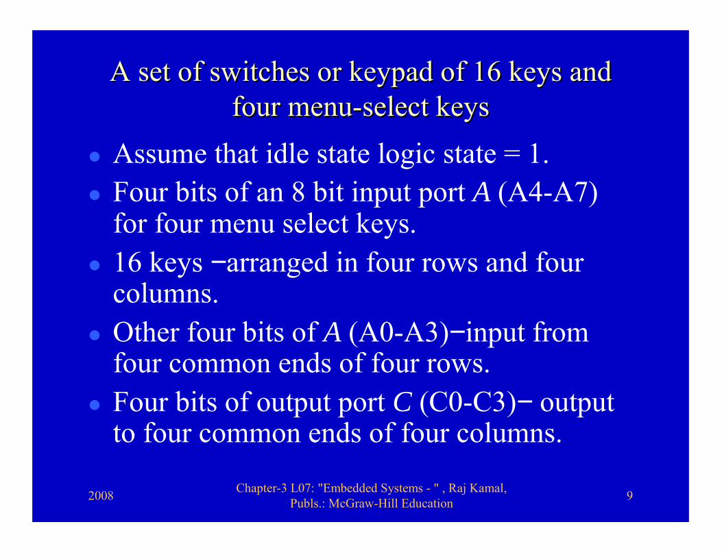
A set of switches or keypad of 16 keys and A set of switches or keypad of 16 keys and four menufour menu--select keysselect keys
� Assume that idle state logic state = 1.� Four bits of an 8 bit input port A (A4-A7)
for four menu select keys. � 16 keys −arranged in four rows and four
columns. � Other four bits of A (A0-A3)−input from
four common ends of four rows. � Four bits of output port C (C0-C3)− output
to four common ends of four columns.

2008 Chapter-3 L07: "Embedded Systems - " , Raj Kamal, Publs.: McGraw-Hill Education 10
Keypad
INT
Data bus
Switchesinputde-bouncer at keypad for Port A bits and four output bits bits from port C for polling
Pole line at 0 for polling a column ofrow at instant t1
Four switches in a row
Sense lines 0-3
A sense line Senses logic high to low transition if switch pressed else high at polling instance t1

2008 Chapter-3 L07: "Embedded Systems - " , Raj Kamal, Publs.: McGraw-Hill Education 11
Parallel input port A and four-bit output port C used for interfacing a set of 16 keys in
keypad and four menu select keys
INT
Data bus
Keypad inputprocessor at device
Poll lines0-3
Menu-select lines (up, down, left, right keys)
Processor
Sense lines 0-3PortsPA0-
PA3PC0-PC3
16 Keys 0, 1, .., 14, 15 in 4 × 4 lines (Polling and sense lines)
PA4-PA7
Data bus
INT
2008 Chapter-3 L07: "Embedded Systems - " , Raj Kamal, Publs.: McGraw-Hill Education 12
A processing element A processing element ── keypad controller, as keypad controller, as it is keypad specific. it is keypad specific.

2008 Chapter-3 L07: "Embedded Systems - " , Raj Kamal, Publs.: McGraw-Hill Education 13
Processing element in the deviceProcessing element in the device� Activates for polling output from port
C ten times each second� Sends C0-C3 = 0000 and after a wait it
reads D0-D7 and A4-A7� Processes the bounces when a key is
pressed. This takes care of bouncing effects.
2008 Chapter-3 L07: "Embedded Systems - " , Raj Kamal, Publs.: McGraw-Hill Education 14
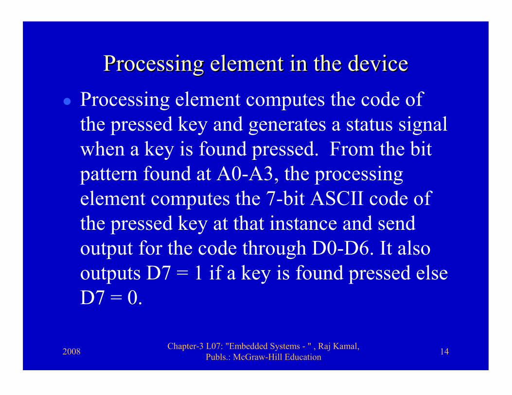
Processing element in the deviceProcessing element in the device� Processing element computes the code of
the pressed key and generates a status signal when a key is found pressed. From the bit pattern found at A0-A3, the processing element computes the 7-bit ASCII code of the pressed key at that instance and send output for the code through D0-D6. It also outputs D7 = 1 if a key is found pressed else D7 = 0.

2008 Chapter-3 L07: "Embedded Systems - " , Raj Kamal, Publs.: McGraw-Hill Education 15
3. Parallel Port Interfacing with 3. Parallel Port Interfacing with encoderencoder

2008 Chapter-3 L07: "Embedded Systems - " , Raj Kamal, Publs.: McGraw-Hill Education 16
EncoderEncoder
• A device, which measures the angular or linear position of a rotating or moving shaft
• Application in robots and industrial plants

2008 Chapter-3 L07: "Embedded Systems - " , Raj Kamal, Publs.: McGraw-Hill Education 17
RotatoryRotatory angle encoderangle encoder
� Multiple tracks on a rotating disk. � Each track has half of the segments
transparent and half opaque.

2008 Chapter-3 L07: "Embedded Systems - " , Raj Kamal, Publs.: McGraw-Hill Education 18
RotatoryRotatory EncoderEncoder
� A has multi-slotted plate. A set of n infrared (IR) LED and phototransistor pairs generate n-bit input for a port.
� The encoder’s each phototransistor interfaces to one parallel port bit

2008 Chapter-3 L07: "Embedded Systems - " , Raj Kamal, Publs.: McGraw-Hill Education 19
RotatoryRotatory Encoder interfacingEncoder interfacing
• Seven inputs─ Five track Rotatoryencoder, one input is from PT at index slot, one input from phase detector circuit
• Six outputs to six LEDs
2008 Chapter-3 L07: "Embedded Systems - " , Raj Kamal, Publs.: McGraw-Hill Education 20
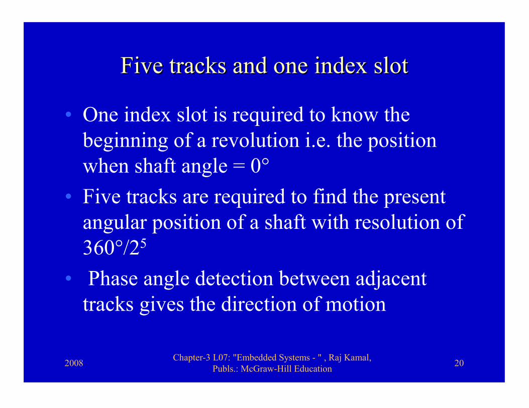
Five tracks and one index slot Five tracks and one index slot
• One index slot is required to know the beginning of a revolution i.e. the position when shaft angle = 0°
• Five tracks are required to find the present angular position of a shaft with resolution of 360°/25
• Phase angle detection between adjacent tracks gives the direction of motion

2008 Chapter-3 L07: "Embedded Systems - " , Raj Kamal, Publs.: McGraw-Hill Education 21
Interfacing of Six LEDInterfacing of Six LED--Phototransistor Pairs Phototransistor Pairs and one phase detector circuit and one phase detector circuit
• Five track Rotatory encoder has six LED-phototransistor (PT) pairs
• Five inputs are PTs from tracks and one input is from PT at index slot
• One input is from phase detector circuit, which finds phase angle between input from two PTs

2008 Chapter-3 L07: "Embedded Systems - " , Raj Kamal, Publs.: McGraw-Hill Education 22
Parallel input port A connected to an encoder Parallel input port A connected to an encoder circuit which sends the rotated or linear circuit which sends the rotated or linear
position of a moving shaftposition of a moving shaft
To 6 LEDs
Adjacent track Phase angle detector
5 tracks 0, 1, 2, 3, 4 input from 5 phototransistors
Index slot detector at 360°
INT
Data bus
Port interfaceat deviceProcessor
Ports
PA0-PA4PA5
PA6
PB0-PB5
PA6 input from index slot phototransistor in the rotating plate

2008 Chapter-3 L07: "Embedded Systems - " , Raj Kamal, Publs.: McGraw-Hill Education 23
SummarySummary
2008 Chapter-3 L07: "Embedded Systems - " , Raj Kamal, Publs.: McGraw-Hill Education 24
We learnt• Parallel port input from switches – A poll
line at logic 0 connects one end of a switch and other end of a switch , which is at 1 in released state, senses 0 when pressed.
• Four sense lines from four switches to four port pins
• Port bit sensed = 0 when switch pressed and = 1 when released
2008 Chapter-3 L07: "Embedded Systems - " , Raj Kamal, Publs.: McGraw-Hill Education 25
We learnt• Each switch or key de-bouncing circuit • Parallel port input from 16-key keypad • Keys assumed to be divided in four columns
and four rows • Four poll lines at logic 0 outputs (from four
port pins) connect four columns of switches• Four sense lines from four switches in a row
to four port pins
2008 Chapter-3 L07: "Embedded Systems - " , Raj Kamal, Publs.: McGraw-Hill Education 26
We learnt• Parallel port input from four menu
keys • Rotatory Encoder • Rotatory Encoder seven inputs─ Five
track Rotatory encoder, one input is from PT at index slot, one input from phase detector circuit
• Rotatory Encoder Six outputs to six LEDs

2008 Chapter-3 L07: "Embedded Systems - " , Raj Kamal, Publs.: McGraw-Hill Education 27
End of Lesson 7 of Chapter 3End of Lesson 7 of Chapter 3