LEONARDO EVOLUTION INSTALLATION MANUAL - · PDF fileLEONARDO EVOLUTION INSTALLATION MANUAL...
84
LEONARDO EVOLUTION INSTALLATION MANUAL LEONARDO EVOLUTION VERSION: 1.7 DATE: FEBRUARY 2010 LANGUAGE: ENGLISH
Transcript of LEONARDO EVOLUTION INSTALLATION MANUAL - · PDF fileLEONARDO EVOLUTION INSTALLATION MANUAL...

LEONARDO EVOLUTIONINSTALLATION MANUAL
LEONARDO EVOLUTION
VERSION: 1.7DATE: FEBRUARY 2010LANGUAGE: ENGLISH

2
VERSION: 1.7 DATE: FEBRUARY 2010
UNIFLAIR SPA POLICY IS ONE OF CONTINUOUS TECHNOLGICAL INNOVATION AND THE COMPANYTHEREFORE RESERVES THE RIGHT TO AMEND ANY DATA HEREIN WITHOUT PRIOR NOTICE.
GB

3
GENERAL INSTRUCTIONS 4Information contained in the manual 4Symbols 4Storage 4Storage after use 4Disposal 4Disposal of the machine 4
SAFETY 6General Instructions 6Warning for lifting and transportation 6Warnings for installation 6Intended use 6Warnings for use 6Safety during maintenance work 6
INTRODUCTION 7Presentation of the system 7
LEONARDO EVOLUTION - DIRECT EXPANSION 10Technical characteristics 10Operating description 13Name and description of the principle components 14Checks to be made on delivery 17Unloading the unit 17Characteristics of the installation area 17Positioning of the unit 17Door opening and removal of the panels 18Door opening 18Internal protection panels 19Electrical connections 20Connection to the drains 21Connection to the gas drain 21Refrigerant connections on air cooled units 22Choosing the diameter of the discharge tube 22
R407C 23R410A 24BACKFLOW LINE DIMENSIONING (LIQUID) 27
Type of oil recommended with COPELANDcompressors 29Type of oil recommended with MANEUROPcompressors 29Type of oil recommended with SANYO compressors 29Type of oil recommended with Scrolltech HCJ 072-HLJ083 compressors 29Connection for water cooled units 30
MANUAL START UP AND SHUT DOWN OF THE UNIT 31SETTING AND ADJUSTMENT 32
Selecting the power supply of the fans 32Setting the regulation and safety devices 35Setting the pressostatic valve (optional on chilled watercooled models only) 35Setting the air flow sensor 35Setting the dirty filter sensors 35
MAINTANENCE 36Three-monthly checks 36Six-monthly checks 36
Annual checks 36Checks to be performed every sixty months 36Cleaning and repalcing the filters 36Troubleshooting 38
LEONARDO EVOLUTION - CHILLED WATER 42Technical characteristics 42Operating description 43Name and description of the principle components 44Checks to be made on delivery 46Unloading the unit 46Characteristics of the installation area 46Positioning of the unit 46Opening of the door and removal of the panels 47Internal protection panels 48Electrical connections 49Connection to the water drain 50Hydraulic connections 51Filling the hydraulic circuit 51Filling the primary circuit 51 Filling the hydraulic circuits of the conditioners 51
MANUAL START UP AND SHUT DOWN OF THE UNIT 52SETTING AND ADJUSTMENT 53
Selecting the power supply of the fans 53Setting the regulation and safety devices 57Setting the air flow sensor 58Setting the dirty filter sensors 58
MAINTENANCE 58Three-monthly checks 58Six-monthly checks 58Annual checks 58Cleaning and replacing the filters 59Servomotor and chilled water valve 60Servomotor and hot water valve 60Troubleshooting 61
LEONARDO EVOLUTION ENERGY SAVING 63Technical characteristics 63Operating description 64Name and description of the principle parts 65
LEONARDO EVOLUTION TWIN-COOL 69Technical characteristics 69Operating description 71Name and description of the principle components 72
ACCESSORIES 77Humidifier 77
Operating principle 78Feed water 78Connections 78
Maintenance 79Electric heaters 80Temperature and humidity sensor 81Connection to fresh air intake 82
Maintenance 83Discharge temperature threshold sensor (only onCHILLED WATER models) 83
Contents

4
GENERAL INSTRUCTIONSInformation contained in the manualThe present manual describes the Leonardo Evolutionconditioning units. It supplies general information and safetyinstructions, unit transportation and installation information,as well as necessary information about how to use the units.It is an integral part of the product.The descriptions and illustrations in this manual are unbinding;"Uniflair S.p.A." reserves the right to make any alterations itsees fit in order to improve the product without having to updatethis document.The illustrations and images in this manual are examplesonly and may differ from practical situations.
SymbolsThe following graphic and linguistic symbols have been usedin this manual:
WARNING! This message may appear beforecertain procedures. Failure to observe thismessage may cause damage to equipment.
WARNING! This message may appear beforecertain procedures. Failure to observe thismessage may cause injury to the operators anddamage the equipment.
StorageThe following conditions must be respected should the unitrequire storing for a given period of time:The packing must be kept intact.The place of storage must be dry (<85% R.H.) and protectedagainst the sun (temperature <50°C).
Storage after useThe unit must be packaged when stored for a long time.
DisposalThe unit is mainly made of recyclable materials which shouldbe separated from the rest of the unit before it is disposed.When disposing of the gas and oil inside the refrigeratingcircuit, consult a specialist company.
Disposal of the machineThe following instructions deal with the disposal of UNIFLAIRmachines.The procedures described below are guidelines only, providedto make the machine disassembling easier. The purpose ofthese operations is to achieve homogeneous materialquantities for disposal or recycling.These instructions are followed by a list of the possible typicalCER 2002 codes to allow an easier disposal of the machineparts.
WARNING! Observe the safety precautions atwork wearing the suitable individual protectiondevices (IPD) and using the appropriateequipments.
WARNING! Maintenance and service operations(disassembling included) must be performed byqualified and expert personnel, aware of theessential precautions.
PRELIMINARY OPERATIONSPower supply and data processing system:• Turn the machine off and unplug it from the power supply
and from the communication system.WARNING! The circuits can be pressurised; anymaintenance and service operation must onlybe carried out by expert and qualified personnel,aware of the essential safety precautions.
WARNING! The machine can contain hot water:adopt all of the essential safety cautions.
Hydraulic circuit:• Drain the hydraulic circuit and disconnect the hydraulic
line.Refrigerating circuit:• Purge the refrigeration system with suitable recovery
equipments to avoid gas leakage in the environment.
DISASSEMBLING THE MACHINEThe following paragraphs describe the main macrocomponentsto facilitate the disassembling, disposal and recycling ofmaterials with appropriate features.To disassemble the machine properly, follow the guidelinesprovided below.• ELECTRICAL PANEL
Remove the electrical panel and dispose its partsfollowing the procedures provided by the relevantstandards. The models equipped with a "clock board" inthe electrical panel have a service battery which mustbe disposed separately.- Materials: electronic parts, electrical cables, metal andplastic supports, batteries.
• COVER PANELSRemove the metal cover and protection panels of themachine.The panels can be made of polypaired materials, that isinsulating material together with metal. In this case,separate the different elements.- Materials: galvanized sheet, aluminium, soundproofpanels: expanded polyurethane, thermoinsulatingpanels: mineral wool.
5
• AIR FILTERSRemove the air filters.- Materials: metallic net, synthetic fibre.
• FINNED COILRemove the finned coils from the machine.- Materials: copper, aluminium, steel.
• HUMIDIFIERIf a humidifier is installed, remove it.- Materials: polypropylene, iron materials.
• ELECTRO-MECHANICAL PARTSFind and remove valves, electro-mechanical andelectronic parts (three-way valves, sensors, etc.) fromthe machine.
• RESISTANCESRemove the resistances if they are installed.- Materials: aluminium, inseparable copper + magnesiumoxide.
• PIPES AND PARTS OF THE REFRIGERATINGCIRCUITFind the connection pipes installed in the machine andseparate them from the other elements.Pipes can be caulked: in this case, before recovery, se-parate the insulating material from the metal pipe.Even the elements of the refrigerating circuit areconsidered as pipes: joints or valves.- Materials: copper, brass, cast iron, steel and plastic.
• PUMPRemove the pump from the machine.- Materials: pump.
• CONDENSERRemove the condenser, if installed.The condenser contains the elements of a machine,equipped with a small electrical panel, fans and a thermalexchange battery, usually characterized by aluminiumstructure and feet made of varnished steel.- Materials: electrical elements, aluminium, steel(varnished).
• BRAZED PLATE EXCHANGERIf installed, remove the brazed plate exchanger.- Materials: INOX AISI braze welding, with an alloycontaining a large amount of silver.
• FANSRemove the fans. Disassemble the metal frame andproceed with the recycling of the metal alloy.- Materials: electro-mechanical elements, iron wrecks.
WARNING! The fans of some machine modelsare integral part of the carrying structure.Removing the fans can compromise the stabilityof the frame. We recommend to pay attentionduring disassembling operations.
• COMPRESSORS AND LIQUID SEPARATORSWARNING! Pay attention to oil contained in thecompressors. Avoid any loss of oil duringoperations. If possible, dispose of oil andcompressors separately.
Finally remove the liquid separators and the compressorsfrom the machine base.- Materials: liquid separators and compressors
• METAL BASEProceed with the recycling of the metal base.- Materials: galvanised sheet.
WARNING! Waste deriving from machinedisassembly must be disposed of and classifiedaccording to CER codes only consultingauthorised and specialist companies.
The following chart contains a partial list of the typical CERcodes applied to waste deriving from disassembling, so itmust be considered just as an indication.
STNEMELE SEDOC2002REC
selbaclacirtcelE 114071
slairetamcitsalP 911061
stroppuslateM 711061
teehsdesinavlaG 704071
muinimulA 204071
tencillateM 504071
erbifcitehtnyS 302051
reppoC 104071
ssarB 104071
noritsaC 504071
leetS 704071
saggnitaregirfeR 106041
yrettaB 406061
lacinahcem-ortcele,spmuPsrosserpmoc,stnemele 409071

6
SAFETYGeneral Instructions
WARNING! Removal of, or tampering with,safety devices is a violation of EUROPEANSAFETY STANDARDS.
WARNING! During installation authorisedpersonnel must wear individual safety devices.
Uniflair S.p.A will only consider itself responsible for the safety,reliability and performance of the machine if:• repair work has only been carried out by authorisedpersonnel;• the electric installation conforms to the standards currentlyin force;• the devices are used in conformity with the relativeinstructions.Carefully read this instruction manual before carrying out anykind of use or maintenance work on the units.Installation, maintenance and use must be carried outrespecting all of the work safety standards.The operator responsible for the above mentioned servicesmust be suitably specialised and possess expert knowledgeof the devices.Uniflair S.p.A refuses all responsibility for damage to peopleor objects due to the inobservance of the safety standards.
Warning for lifting and transportationLifting and transportation of the units must be carried out byspecialised personnel as described in the relative paragraphs.The load must always be solidly anchored to the bearingelement of the lifting equipment and means of transport. No-one must remain near the suspended load, nor in the workingarea of the crane, forklift truck or any other lifting equipmentor means of transport. Adopt all of the cautions provided bythe relevant safety standards, in order to prevent any possibledamage to people or objects.
Warnings for installationAny type of work on the electrical installation must only becarried out by specialised technicians who are experts inthis field.Specialised technical personnel must use appropriateequipment when checking the grounding of devices.Installation may only take place in locations where there isNO public access.
Intended useLeonardo Evolution air conditioning units have been designedand produced to carry out air conditioning, within the limitsand methods described in the present manual. The airconditioners must be used exclusively in internalenvironments.No modifications may be made to the units or their partswithout explicit written consent from Uniflair S.p.A.
Warnings for useOnly use the machinery for the purpose for which it wasdesigned and manufactured.
Environmental limits for useThe environmental conditions for the use of Leonardo airconditioners are fall within the following values:
• Tmin=18°C • Tmax=30°C• %rHmin=30% • %rHmax=70%
Safety during maintenance workAll repair work must be carried out by professionally qualifiedpersonnel authorised by Uniflair S.p.A.Unplug the machine form the power supply before startingany maintenance work.While drawing up this manual, we have considered all of theoperations which are part of normal maintenance operations.
N.B. Do not carry out any work which has not been specifiedin this manual.

7
AIR FLOWIn the LEONARDO EVOLUTION conditioners, the air can flow upwards or downwards (UPFLOW / DOWNFLOW).
UPFLOWUpflow units (with upwards air discharge) are designed to distribute the air through a system of ducts or by means of a falseceiling. Air intake is usually through the front of the unit, but versions are also available with air intake through the rear or thebase of the unit.
INTRODUCTION
Presentation of the systemThe Leonardo Evolution™ precision air conditioners are designed for environments which are characterised by the presenceof highly technologically advanced equipment: telecomms and internet centres, data processing rooms and any type ofenvironment which is characterized by high concentrations of power.
The Leonardo Evolution series consists of 4 types of conditioners:• Direct expansion• Chilled water• Energy Saving• Twin-Cool
DOWNFLOWDownflow units (with downwards air discharge) handle large volumes of air which are distributed uniformly into the environmentby means of a void under a raised access floor. The air enters the unit directly from the environment, or through a ventilatedor false ceiling.
8
Identifying prefix of the Leonardo family
Air discharge
U = Upflow (upwards discharge)D = Downflow (downwards discharge)
Operating typology
C = Chilled water unitsA = Air cooled direct expansion unitsW = Water cooled direct expansion unitsT = Air cooled twin cool unitsD = Water cooled twin cool unitsE = Energy saving units
Fan typology
V = Radial Electronically Commutated fansR = Radial fans
MODELSThe code which distinguishes the models is composed of 4 characters:
IDENTIFICATON PLATEThe units can be identified by the identification plate which is placed in the electrical panel of the machine. The model andany eventual accessories which are installed are indicated by an "X" in the corresponding boxThe plate carries the following data:• Model and series number of the machine.• Type of power supply.• Power absorbed by the unit and the single components.• Current absorbed by the unit and the single components.• The set points of the cooling circuit pressostatic valve and safety valve.• Type of refrigerant.• Loading or pre-loading of each cooling circuit.
Indicative cooling capacity
Number of compressors installed
Number of cooling circuits
Power supply voltage
A = 400 V / 3Ph (+N) / 50 HzB = 230 V / 1 Ph / 50 Hz
TDAV1422A(H) TDEV1422A(H) SERIAL No.
TUAV1422A(H) TUEV1422A(H) TDWV1422A(H) TDDV1422A(H) TDTV1422A(H) TUWV1422A(H) TUDV1422A(H) TUTV1422A(H)
TENS. 400V/3Ph+N/50Hz AUX. 24 VOLTNO. TENS. (V) OA (A) [/1] FLA (A) [/1] LRA (A) [/1] P (kW) [TOT]
COMPRESSOR 2 400/3 10,7 14,0 98 11,2FAN 2 400/3 4,7 5,6 0 5,42HUMIDIFIER 1 400/3 9,1 0,0 0 6,29 HEATERS STD 3 400/3 7,2 0,0 0 15 ENHANCED HEATERS 3 400/3 8,7 0,0 0 18 UNIT (STD HEATERS) (*) 41,7 26,02
UNIT (ENHANCED HEATERS) (*) 46,0 29,02
UNIT (STD HEATERS+CAL max) (*) 41,7+10,5x1Ph 28,36
UNIT (ENH HEATERS+CAL max) (*) 46+10 5x1Ph 31 36 UNIT (ENH. HEATERS+CAL max) (*) 46+10,5x1Ph 31,36
Icu=15kA (CEI EN 60947-2) / (*) in operating conditions at 400VTSR STOP: 310 °C MAN. RESETTSRA STOP: 328 °C MAN. RESETAP1-2 STOP: 26,5 bar MAN. RESETSAFETY VALVE OPENS AT: 30 barCHARGE: R407C kg/circ. R22 kg/circ.PRECHARGE: DRY NITROGEN N2
FAC-SIMILE
FAC-SIMILE
9
SYMBOLS APPLIED TO THE MACHINES
LOBMYS GNINAEM
egatlovhgiH
segdeprahS
strapgnivoM
LOBMYS GNINAEM
erachtiweldnah:ELIGARF
yrdaniderotsebtsumtinudegakcapeht:SNOITIDNOCPMADNIEROTSTONODecalp
tinudegakcapehtfoytivargfoertnecehtswohs:YTIVARGFOERTNEC
secruostaehmorfyawaderotsebtsumtinueht:TAEHMORFYAWAPEEK
tinudegakcapehtfonoitisoptcerrocehtsetacidni:PUEDISSIHT
ehtnihtiwecalpaniderotsebtsumtinudegakcapeht:STIMILERUTAREPMETstimilerutarepmetdetacidni
skoohgnisustinudegakcapehttfiltonod:SKOOHESUTONOD
dekcatsebtontsumstinudegakcapeht:KCATSTONOD
SYMBOLS APPLIED TO THE PACKAGES

10
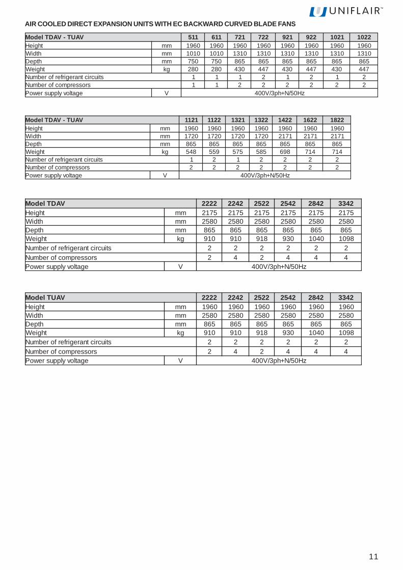
LEONARDO EVOLUTION - DIRECT EXPANSIONTechnical characteristicsAIR COOLED DIRECT EXPANSION UNITS WITH BACKWARD CURVED BLADE FANS
RAUT-RADTledoM A115 A116 A127 A227 A129 A229 A1201 A2201thgieH mm 0691 0691 0691 0691 0691 0691 0691 0691
htdiW mm 0101 0101 0131 0131 0131 0131 0131 0131htpeD mm 057 057 568 568 568 568 568 568
thgieW gk 082 013 034 744 034 744 034 744stiucrictnaregirferforebmuN 1 1 1 2 1 2 1 2
srosserpmocforebmuN 1 1 2 2 2 2 2 2egatlovylppusrewoP V zH05/N+hp3/V004
RAUT-RADTledoM A1211 A2211 A1231 A2231 A2241 A2261 A2281thgieH mm 0691 0691 0691 0691 0691 0691 0691
htdiW mm 1271 1271 1271 1271 2712 2712 2712htpeD mm 568 568 568 568 568 568 568
thgieW gk 845 955 575 585 896 417 417stiucrictnaregirferforebmuN 1 2 1 2 2 2 2
srosserpmocforebmuN 2 2 2 2 2 2 2egatlovylppusrewoP V zH05/N+hp3/V004
RADTledoM 2222 2422 2252 2452 2482 2433thgieH mm 5712 5712 5712 5712 5712 5712
htdiW mm 0852 0852 0852 0852 0852 0852htpeD mm 568 568 568 568 568 568
thgieW gk 019 019 819 039 0401 8901stiucrictnaregirferforebmuN 2 2 2 2 2 2
srosserpmocforebmuN 2 4 2 4 4 4egatlovylppusrewoP V zH05/N+hp3/V004
RAUTledoM 2222 2422 2252 2452 2482 2433thgieH mm 0691 0691 0691 0691 0691 0691
htdiW mm 0852 0852 0852 0852 0852 0852htpeD mm 568 568 568 568 568 568
thgieW gk 019 019 819 039 0401 8901stiucrictnaregirferforebmuN 2 2 2 2 2 2
srosserpmocforebmuN 2 4 2 4 4 4egatlovylppusrewoP V zH05/N+hp3/V004
11
VAUT-VADTledoM 115 116 127 227 129 229 1201 2201thgieH mm 0691 0691 0691 0691 0691 0691 0691 0691
htdiW mm 0101 0101 0131 0131 0131 0131 0131 0131htpeD mm 057 057 568 568 568 568 568 568
thgieW gk 082 082 034 744 034 744 034 744stiucrictnaregirferforebmuN 1 1 1 2 1 2 1 2
srosserpmocforebmuN 1 1 2 2 2 2 2 2egatlovylppusrewoP V zH05/N+hp3/V004
AIR COOLED DIRECT EXPANSION UNITS WITH EC BACKWARD CURVED BLADE FANS
VAUT-VADTledoM 1211 2211 1231 2231 2241 2261 2281thgieH mm 0691 0691 0691 0691 0691 0691 0691
htdiW mm 0271 0271 0271 0271 1712 1712 1712htpeD mm 568 568 568 568 568 568 568
thgieW gk 845 955 575 585 896 417 417stiucrictnaregirferforebmuN 1 2 1 2 2 2 2
srosserpmocforebmuN 2 2 2 2 2 2 2egatlovylppusrewoP V zH05/N+hp3/V004
VADTledoM 2222 2422 2252 2452 2482 2433thgieH mm 5712 5712 5712 5712 5712 5712
htdiW mm 0852 0852 0852 0852 0852 0852htpeD mm 568 568 568 568 568 568
thgieW gk 019 019 819 039 0401 8901stiucrictnaregirferforebmuN 2 2 2 2 2 2
srosserpmocforebmuN 2 4 2 4 4 4egatlovylppusrewoP V zH05/N+hp3/V004
VAUTledoM 2222 2422 2252 2452 2482 2433thgieH mm 0691 0691 0691 0691 0691 0691
htdiW mm 0852 0852 0852 0852 0852 0852htpeD mm 568 568 568 568 568 568
thgieW gk 019 019 819 039 0401 8901stiucrictnaregirferforebmuN 2 2 2 2 2 2
srosserpmocforebmuN 2 4 2 4 4 4egatlovylppusrewoP V zH05/N+hp3/V004

12
CHILLED WATER DIRECT EXPANSION UNITS WITH BACKWARD CURVED BLADE FANS
RWUT-RWDTledoM 116 129 1231 2261 2281thgieH mm 0691 0691 0691 0691 0691
htdiW mm 0101 0131 0271 1712 1712htpeD mm 057 568 568 568 568
thgieW gk 013 034 575 417 417stiucrictnaregirferforebmuN 1 1 1 2 2
srosserpmocforebmuN 1 2 2 2 2egatlovylppusrewoP V zH05/N+hp3/V004
RWDTledoM 2422 2452 2482 2433thgieH mm 5712 5712 5712 5712
htdiW mm 0852 0852 0852 0852htpeD mm 568 568 568 568
thgieW gk 699 0201 0211 0411stiucrictnaregirferforebmuN 2 2 2 2
srosserpmocforebmuN 4 4 4 4egtalovylppusrewoP V zH05/N+hp3/V004
RWUTledoM 2422 2452 2482 2433thgieH mm 0691 0691 0691 0691
htdiW mm 0852 0852 0852 0852htpeD mm 568 568 568 568
thgieW gk 699 0201 0211 0411stiucrictnaregirferforebmuN 2 2 2 2
srosserpmocforebmuN 4 4 4 4egtalovylppusrewoP V zH05/N+hp3/V004

13
AIR COOLED DIRECT EXPANSION UNITS (DXA)The air cooled DX units extract heat from the room and transfer it tothe outside using air cooled refrigerant heat exchangers (condensers).The room unit and external condenser form an autonomous sealed circuitonce installed. The UNIFLAIR remote condensers used with LEONARDOunits include a precise electronic system to regulate the fan speed toensure trouble-free operation throughout the year under a wide range ofexternal air temperatures. Special attention has been paid to the acousticdesign of the condensers to minimise noise levels. A wide range ofcombinations is available to meet different site requirements.
WATER COOLED DIRECT EXPANSION UNITS (DXW)In the DX water cooled units, the heat extracted from the room istransferred to water via a stainless steel brazed plate exchanger withinthe unit.The cooling water may be fed from the mains supply, a cooling tower ora well (open circuit), or recycled in a closed loop cooled by externalcoolers.In the latter case, an anti-freeze mixture of water and ethylene glycol isnormally used.The water cooled units have the advantage that the refrigerant circuitsare charged and sealed in the factory. This makes installation extremelysimple, eliminating the need for any site-installed refrigerant pipework.
CHILLED WATER DIRECT EXPANSION UNITS WITH EC BACKWARD CURVED BLADE FANS
VWUT-VWDTledoM 116 129 1231 2261 2281thgieH mm 0691 0691 0691 0691 0691
htdiW mm 0101 0131 0271 1712 1712htpeD mm 057 568 568 568 568
thgieW gk 082 034 575 417 417stiucrictnaregirferforebmuN 1 1 1 2 2
srosserpmocforebmuN 1 2 2 2 2egatlovylppusrewoP V zH05/N+hp3/V004
Operating description
VWDTledoM 2422 2452 2482 2433thgieH mm 5712 5712 5712 5712
htdiW mm 0852 0852 0852 0852htpeD mm 568 568 568 568
thgieW gk 699 0201 0211 0411stiucrictnaregirferforebmuN 2 2 2 2
srosserpmocforebmuN 4 4 4 4egtalovylppusrewoP V zH05/N+hp3/V004
VWUTledoM 2422 2452 2482 2433thgieH mm 0691 0691 0691 0691
htdiW mm 0852 0852 0852 0852htpeD mm 568 568 568 568
thgieW gk 699 0201 0211 0411stiucrictnaregirferforebmuN 2 2 2 2
srosserpmocforebmuN 4 4 4 4egtalovylppusrewoP V zH05/N+hp3/V004

14
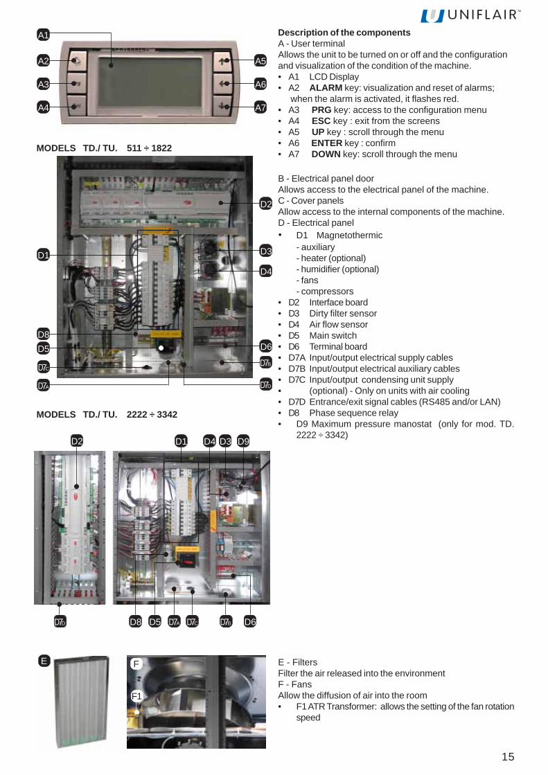
Name and description of the principle components
A
B
C
A User terminalB Electrical panel doorC Cover panelsD Electrical panelE FiltersF FansG Cooling circuitH Brazed plate heat exchanger(present in chilled watermodels)
H
E
D
F
G
DE
F
G
MODELS TD./ TU. 511 ÷ 1822
MODELS TD./ TU. 2222 ÷ 3342
15
Description of the componentsA - User terminalAllows the unit to be turned on or off and the configurationand visualization of the condition of the machine.• A1 LCD Display• A2 ALARM key: visualization and reset of alarms;
when the alarm is activated, it flashes red.• A3 PRG key: access to the configuration menu• A4 ESC key : exit from the screens• A5 UP key : scroll through the menu• A6 ENTER key : confirm• A7 DOWN key: scroll through the menu
A2
A3
A4
A5
A6
A7
A1
B - Electrical panel doorAllows access to the electrical panel of the machine.C - Cover panelsAllow access to the internal components of the machine.D - Electrical panel• D1 Magnetothermic
- auxiliary- heater (optional)- humidifier (optional)- fans- compressors
• D2 Interface board• D3 Dirty filter sensor• D4 Air flow sensor• D5 Main switch• D6 Terminal board• D7A Input/output electrical supply cables• D7B Input/output electrical auxiliary cables• D7C Input/output condensing unit supply• (optional) - Only on units with air cooling• D7D Entrance/exit signal cables (RS485 and/or LAN)• D8 Phase sequence relay• D9 Maximum pressure manostat (only for mod. TD.
2222 ÷ 3342)
D5
D1
D2
D3
D6
D7A
D4
D8
D7BD7C
D7D
MODELS TD./ TU. 511 ÷ 1822
MODELS TD./ TU. 2222 ÷ 3342
FE
F1
E - FiltersFilter the air released into the environmentF - FansAllow the diffusion of air into the room• F1 ATR Transformer: allows the setting of the fan rotation
speed
D2 D1
D7A D7C D7BD7D
D3D4 D9
D5 D6D8
16
H H1
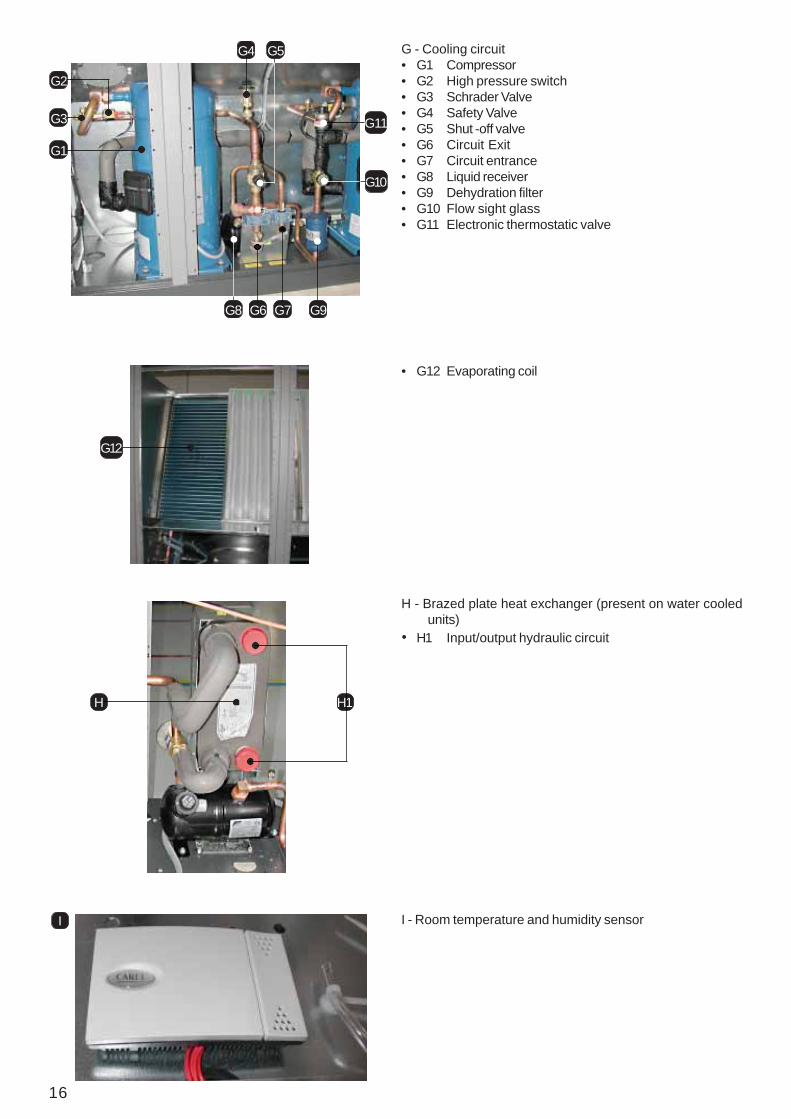
G1
G2
G3
G4 G5
G6 G7G8
G10
G11
G9
G - Cooling circuit• G1 Compressor• G2 High pressure switch• G3 Schrader Valve• G4 Safety Valve• G5 Shut -off valve• G6 Circuit Exit• G7 Circuit entrance• G8 Liquid receiver• G9 Dehydration filter• G10 Flow sight glass• G11 Electronic thermostatic valve
G12
• G12 Evaporating coil
H - Brazed plate heat exchanger (present on water cooledunits)
• H1 Input/output hydraulic circuit
I I - Room temperature and humidity sensor
17
Checks to be made on deliveryWARNING! Dispose of the packaging inappropriate collection points.
The Leonardo Evolution units are packaged in wooden cratesor anchored to a pallet and covered in cardboard.Check that the delivery is complete and inform the carrier ofany damage to the unit which may be attributed too carelessor inappropriate transportation. In particular, check anyeventual damage to the panel in which the user terminal ismounted.Lifting and moving the unit must be carried out by amechanical lifter, supplied with a sling made up of textilebelts, which, fixed under the machine, limits excessive stresson the upper edges.The following must be contained within the packaging:• The Leonardo Evolution unit;• Leonardo Use and Installation Manual;• Leonardo unit electrical diagrams;• Leonardo unit cooling circuit diagrams;• Leonardo unit installation diagrams;• List of spare parts;• CE declaration with a list of the European standards to
which the machine must conform;• guarantee conditions
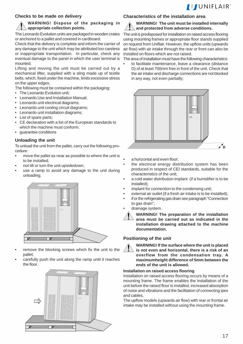
Unloading the unitTo unload the unit from the pallet, carry out the following pro-cedure:• move the pallet as near as possible to where the unit is
to be installed;• not tilt or turn the unit upsidedown;• use a ramp to avoid any damage to the unit during
unloading;
• remove the blocking screws which fix the unit to thepallet;
• carefully push the unit along the ramp until it reachesthe floor.
Characteristics of the installation areaWARNING! The unit must be installed internallyand protected from adverse conditions.
The unit is predisposed for installation on raised access flooringusing mounting frames or appropriate floor stands suppliedon request from Uniflair. However, the upflow units (upwardsair flow) with air intake through the rear or front can also beinstalled on floors which are not raised.The area of installation must have the following characteristics:• to facilitate maintenance, leave a clearance (distance
D) of at least 700mm free in front of the unit. Check thatthe air intake and discharge connections are not blockedin any way, not even partially;
• a horizontal and even floor;• the electrical energy distribution system has been
produced in respect of CEI standards, suitable for thecharacteristics of the unit;
• a cold water distribution implant (if a humidifier is to beinstalled);
• implant for connection to the condensing unit;• external air outlet (if a fresh air intake is to be installed);• if or the refrigerating gas drain see paragraph "Connection
to gas drain";• drainage system.
WARNING! The preparation of the installationarea must be carried out as indicated in theinstallation drawing attached to the machinedocumentation.
Positioning of the unitWARNING! If the surface where the unit is placedis not even and horizontal, there is a risk of anoverflow from the condensation tray. Amaximumheight difference of 5mm between theends of the unit is allowed.
Installation on raised access flooringInstallation on raised access flooring occurs by means of amounting frame. The frame enables the installation of theunit before the raised floor is installed, increased absorptionof noise and vibrations and the facilitation of connecting ipesand cables.The upflow models (upwards air flow) with rear or frontal airintake may be installed without using the mounting frame.
D
18
Installation of the mounting frameTo install the unit on raised flooring using the mounting fra-me, carry out the following procedures:• a flexible seal at least 5 mm thick should be fitted
between the raised floor panels and the mounting framewhich should also be isolated from the metallic floorstructure;
• position the unit of the mounting frame and fix it usingthe M8 screw inserts found on the base of the unit.
Installation on flooring which is not raisedInstallation on flooring which is not raised can occur withoutusing bases, but only on upflow models(upwards air flow) with rear or frontal air intake. Installation onthis type of floor does not require any additional operationbesides that of normal positioning.Installation of the floor standTo install the unit on the floor stand, carry out the followingprocedures:• position the unit on the floor stand;• fix the unit to the floor stand using the M8 screw inserts
found on the base of the unit.
basamento condizionatore
zoccolo unità
Door opening and removal of the panels
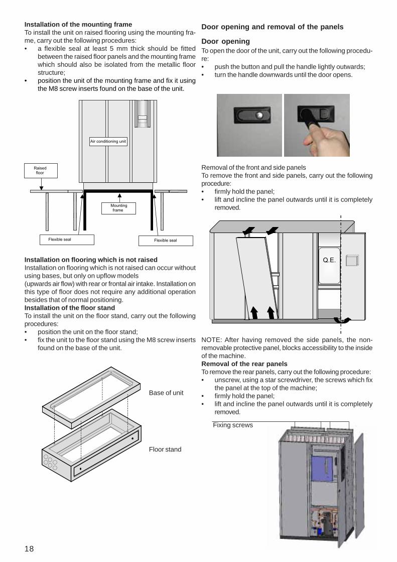
Door openingTo open the door of the unit, carry out the following procedu-re:• push the button and pull the handle lightly outwards;• turn the handle downwards until the door opens.
Removal of the front and side panelsTo remove the front and side panels, carry out the followingprocedure:• firmly hold the panel;• lift and incline the panel outwards until it is completely
removed.
Q.E.
NOTE: After having removed the side panels, the non-removable protective panel, blocks accessibility to the insideof the machine.Removal of the rear panelsTo remove the rear panels, carry out the following procedure:• unscrew, using a star screwdriver, the screws which fix
the panel at the top of the machine;• firmly hold the panel;• lift and incline the panel outwards until it is completely
removed.
Fixing screws
Flexible seal Flexible seal
Mountingframe
Raisedfloor
Air conditioning unit
Base of unit
Floor stand
19
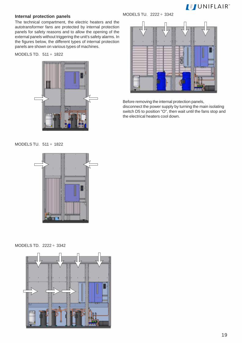
Internal protection panelsThe technical compartment, the electric heaters and theautotransformer fans are protected by internal protectionpanels for safety reasons and to allow the opening of theexternal panels without triggering the unit's safety alarms. Inthe figures below, the different types of internal protectionpanels are shown on various types of machines.
Before removing the internal protection panels,disconnect the power supply by turning the main isolatingswitch D5 to position "O", then wait until the fans stop andthe electrical heaters cool down.
MODELS TD. 511 ÷ 1822
MODELS TU. 511 ÷ 1822
MODELS TD. 2222 ÷ 3342
MODELS TU. 2222 ÷ 3342
20
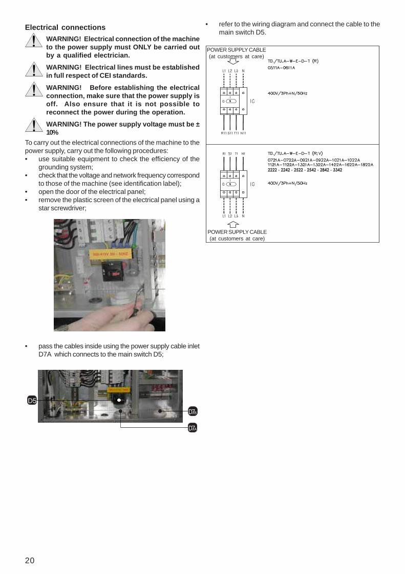
Electrical connectionsWARNING! Electrical connection of the machineto the power supply must ONLY be carried outby a qualified electrician.
WARNING! Electrical lines must be establishedin full respect of CEI standards.
WARNING! Before establishing the electricalconnection, make sure that the power supply isoff. Also ensure that it is not possible toreconnect the power during the operation.
WARNING! The power supply voltage must be ±10%
To carry out the electrical connections of the machine to thepower supply, carry out the following procedures:• use suitable equipment to check the efficiency of the
grounding system;• check that the voltage and network frequency correspond
to those of the machine (see identification label);• open the door of the electrical panel;• remove the plastic screen of the electrical panel using a
star screwdriver;
D5
D7A
D7B
• pass the cables inside using the power supply cable inletD7A which connects to the main switch D5;
• refer to the wiring diagram and connect the cable to themain switch D5.
2222 - 2242 - 2522 - 2542 - 2842 - 3342
POWER SUPPLY CABLE(at customers at care)
POWER SUPPLY CABLE(at customers at care)

21
Connection to the drainsThe condensed water drains from the tray through a siphonedflexible tube fitted in the unit.If the conditioner is fitted with a humidifier, the condensatedrain tray and the humidifier drain connection must beconnected to the drains of the building.Direct connection to the drains of the buildingConnect the drainage tube of the unit to the drains of thebuilding using a rubber or plastic tube with an internal diameterof 25 mm.The external drainage tube must be siphoned in order to avoidunpleasant odours. Maintain a minimum slope of 1%downstream of the siphon.
Once the connections have been made, pour water into thecondensate drain until the siphon inside the unit is full.
The external drainage tube must be siphoned to avoidunpleasant odours and an overflow of the water from the trayof the humidifier. Maintain a minimum slope of 1% downstreamof the siphon.
Once the connections have been made, pour water into thecondensate collection tray of the Leonardo unit and in thecondensate collection tray of the humidifier until both siphonsare full.
Connection to the gas drainThe cooling circuit is equipped with a safety valve for thedischarge of the refrigerant gas.The intervention of the valve pressurises the discharge of therefrigerant fluid, possibly also to high temperatures; in thecase of installation in a closed environment, where there isthe risk of causing damage to people nearby, a conveyingtube must be used from the discharge to outside the room;this must be done in such a way that the operation of thevalve is not affected: it must not create a full flow, a counter-pressure higher than 10% of the pressure of the calibration.Where it is not possible to install a conveying tube it is goodpractice to create adequate aeration of the environment, andindicate, through specific signs, the presence of the drain.Also check that the discharge of the valve does not takeplace behind the electrical boards or electrical equipment.
U7
U4
SAFETY VALVEOUTLET
Connection to the humidifier (optional) and to the drainsof the building
WARNING! The water discharged from thehumidifier is at a very high temperature. Thedrainage tube has to withstand hightemperatures (at least 100°C) and must be keptaway from electrical cables.
Connect the drainage tube of the unit to the collection tray(U4) of the humidifier.Connect the drainage tube of the humidifier (U7) to the drainsof the building using a rubber or plastic tube, which is resistantto high temperatures (minimum 100 °C) with an internaldiameter of 32 mm.
To connect the auxiliary connections to the terminal board,carry out the following procedures:• pass the cables through the power supply cable inlet
D7B;
D5
D7A
D7B
• refer to the wiring diagram and carry out the connectionto the terminal board.
DIGITAL CONFIGURABLE INPUTS
Terminal board 51-20- User- ON - OFF Remote- Flooding sensor (SAS)Terminal board 52-20- User- ON-OFF Remote- Fire-smoke (SFF)Terminal board 50-20- User- ON-OFF Remote- Tools (ATA-BTA-AUA-BUA)
20
20
20
20
50
51
52
Drain
%Siphon
Minimum slope
Drain
%Siphon
Minimum slope

22
Refrigerant connections on air cooled unitsInstallation guide
WARNING! The pipes must always be protected from the sun.
C
1/100
B
A
C
1/100
A
MAX.
5 m
B
A
1/100 B
MAX.
5 m MAX.
15 m
C
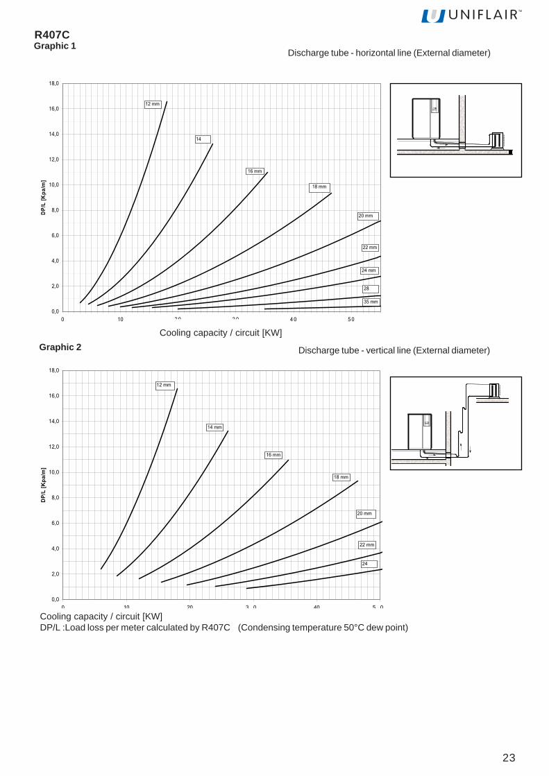
Choosing the diameter of the discharge tubeThe discharge line must be sized in such a way that it guarantees the flow of oil, in particular when operating at partial load,avoiding the return of the condensate refrigerant to the head of the compressor and prevent excessive vibration and noisedue to the pulsations of hot gas, vibrations of the compressor, or both.Even if it would be preferable to have low losses of the load along the line, an oversized discharge line is necessary toreduce the speed of the refrigerant so that it does not provoke a reduction in its speed and therefore reduce the flow of oil.Moreover, when the machine uses more compressors for the cooling circuit, the discharge line must transport the oil at alloperating levels.The minimum diameters needed to guarantee the flow of oil can be found in Graphics 1 -2 for the horizontal and vertical linesrespectively.In the installation of machines which have more compressors per circuit, the vertical discharge line, sized in order toguarantee the flow of oil at minimum load, may cause excessive loss of load when operating at its maximum level; in thiscase it is possible to use pipes with a larger diameter together with an oil separator.The loss of load along the discharge line causes an increase in the condensing temperature and therefore a decrease in thecooling capacity of the conditioner. Please note that each percentage point of decrease in the cooling capacity correspondsto a decrease of 1°C of the maximum operating temperature. Normally the systems are sized in such a way that the lossof load from the discharge line does not cause a decrease in the efficiency of the machine of more than -3%.The responsibility of establishing the refrigerant line between the condensing unit and the external unit lieswith the installer.
23
0,0
2,0
4,0
6,0
8,0
10,0
12,0
14,0
16,0
18,0
0 10 2 0 3 0 4 0 5 0
Resa frigorifera/circuito [KW]
DP
/L [
Kp
a/m
]
12 mm
14
18 mm
20 mm
22 mm
35 mm
24 mm
28
16 mm
0,0
2,0
4,0
6,0
8,0
10,0
12,0
14,0
16,0
18,0
0 10 20 3 0 40 5 0
Resa frigorifera/circuito [KW]
DP
/L [
Kp
a/m
]
12 mm
14 mm
16 mm
18 mm
20 mm
22 mm
24
Tubazioni di mandata - linea orizzontale Grafic
DP/L :Perdita di carico per metro calcolata per R407C (Temperatura di condensazione 50°C dew point)
Tubazioni di mandata - linea verticale Grafic
Discharge tube - horizontal line (External diameter)
Discharge tube - vertical line (External diameter)
Cooling capacity / circuit [KW]DP/L :Load loss per meter calculated by R407C (Condensing temperature 50°C dew point)
Graphic 2Cooling capacity / circuit [KW]
R407CGraphic 1

24
R410AGraphic 1
Discharge tube - horizontal line
DP/L
[kPa
/m]
0,0
2,0
4,0
6,0
8,0
10,0
12,0
14,0
16,0
18,0
0 10 20 30 40 50
Cooling capacity/circuit [kW]
12 mm 14 mm
16 mm
18 mm
20 mm
22 mm
24 mm
28 mm
Graphic 3
0,0 5,0 10,0 15,0 20,0 25,0 30,0 35,0 40,0
Lunghezza Equivalente [m]
DP/L=3
DP/L=1
DP/L=2
DP/L=4
DP/L=5
DP/L=6
DP/L=7
DP/L=8
DP/L=10DP/L=12DP/L=14,53 -Non consentito
1 -Ideale
2 -Consentito
Not allowed
Allowed
Ideal
Equivalent lenght

25
Discharge tube - vertical line
Graphic 2
0 10 20 30 40 50
0,0
2,0
4,0
6,0
8,0
10,0
12,0
14,0
16,0
18,0DP
/L [k
Pa/m
]
Cooling capacity/circuit [kW]
12 mm 14 mm
16 mm
18 mm
20 mm
22 mm
24 mm
DP/L : Pressure drop per metre based on R410A
Graphic 3
-5 0 5 10 15 20 25 30 35 40
Equivalent line [m]
3 - Non consentito - Unacceptable
2 - Consentito - Acceptable
1 - Ideale - Recommended
DP/L = 14 DP/L = 12 DP/L = 10 DP/L = 8
DP/L = 7
DP/L = 6
DP/L = 5
DP/L = 4
DP/L = 3
DP/L = 2
DP/L = 1
26
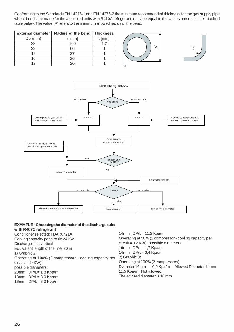
Conforming to the Standards EN 14276-1 and EN 14276-2 the minimum recommended thickness for the gas supply pipewhere bends are made for the air cooled units with R410A refrigerant, must be equal to the values present in the attachedtable below. The value ̀ R' refers to the minimum allowed radius of the bend.
retemaidlanretxE dnebehtfosuidaR ssenkcihT)mm(eD ]mm[r ]mm[t
82 001 2,122 66 181 72 161 62 121 02 1
De r
t
C ooling capacity/circuit atpartial load operation (50)%
C ooling capacity/circuit atfull load operation (100)%
E quivalent length
No
Chart 3
Line s izing
T ype of line
Chart 2
Vertical line
Chart1
Horizontal line
C ooling capacity/circuit atfull load operation (100)%
DP/L (100%)Allowed diameters
T andem unit
Allowed diameters
Not allowed diameterIdeal diameterAllowed diameter but no recomended
Acceptable
Ideal
Unacceptable
Y es
only R407C
Line sizing R407C
EXAMPLE - Choosing the diameter of the discharge tubewith R407C refrigerantConditioner selected: TDAR0721ACooling capacity per circuit: 24 KwDischarge line: verticalEquivalent length of the line: 20 m1) Graphic 2:Operating at 100% (2 compressors - cooling capacity percircuit = 24KW):possible diameters:20mm DP/L= 1,8 Kpa/m18mm DP/L= 3,0 Kpa/m16mm DP/L= 6,0 Kpa/m
14mm DP/L= 11,5 Kpa/mOperating at 50% (1 compressor - cooling capacity percircuit = 12 KW): possible diameters:16mm DP/L= 1,7 Kpa/m14mm DP/L= 3,4 Kpa/m2) Graphic 3:Operating at 100% (2 compressors)Diameter 16mm 6,0 Kpa/m Allowed Diameter 14mm11,5 Kpa/m Not allowedThe advised diameter is 16 mm

27
BACKFLOW LINE DIMENSIONING (LIQUID)To avoid gas development inside the line and to ensure anadequate pressure is reached inside the laminating unit, theliquid line must be correctly dimensioned. Generally, thesystems are dimensioned so that pressure loss along theline causes a variation of the saturation temperature between0,5 K and 1 K
During the installation of the cooling unit, a solenoidvalve should be fitted on the liquid line between theinner unit and the external condenser, to avoidmalfunctioning and to protect the compressor fromunwanted liquid migration during start- up.
Liquid line external diameters
Refrigerant R407C and R410A
Remote air cooled condenser R410A
*AUT-*ADTLEDOM 1150 1160 1270 2270 1290 2290 1201
/rebmuN)2()1(ledomdetsegguS
x11660PAC
x11660PAC
x11080PAC
x21330PAC
x11101PAC
x21630PAC
x11031PAC
*AUT-*ADTLEDOM 2201 1211 2211 1131 2231 2241 2261 2281
/rebmuN)2()1(ledomdetsegguS
x21150PAC
x11031PAC
x21150PAC
x11031PAC
x12081PAC
x21660PAC
x12081PAC
x21080PAC
x12002PAC
x21080PAC
x12003PAC
x21101PAC
(1) With fan speed control(2) External temperature = 35°C
Remote air cooled condenser R407C
*AUT-*ADTLEDOM 1150 1160 1270 2270 1290 2290 1201
/rebmuN)2()1(ledomdetsegguS
x11660LAC
x11660LAC
x11080LAC
x21330LAC
x11101LAC
x21630LAC
x11031LAC
*TUT-*AUT-*TDT-*ADT
LEDOM1150 1160 1290-1270 2290-2270 2241-2231 2222 2252 - -
1231-1201 2211-2201 2281-2261 2422 2452 2482 2433
A014R+C704R x1mm61
x1mm61
x1mm61
x2mm61
x2mm61
x2mm81
x2mm81
x2mm22
x2mm22
*AUT-*ADTLEDOM 2222 2422 2252 2452 2482 2433
/rebmuN)2()1(ledomdetsegguS
x12002PAC
x12002PAC
x12003PAC
x22003PAC
x12004PAC
x22005PAC
*TUT-*AUT-*TDT-*ADTLEDOM 2201 1211 2211 1131 2231 2241 2261 2281
/rebmuN)2()1(ledomdetsegguS
x21150LAC
x11031LAC
x21150LAC
x11031LAC
x12081LAC
x21660LAC
x12081LAC
x21080LAC
x12002LAC
x21080LAC
x12003LAC
x21101LAC
28
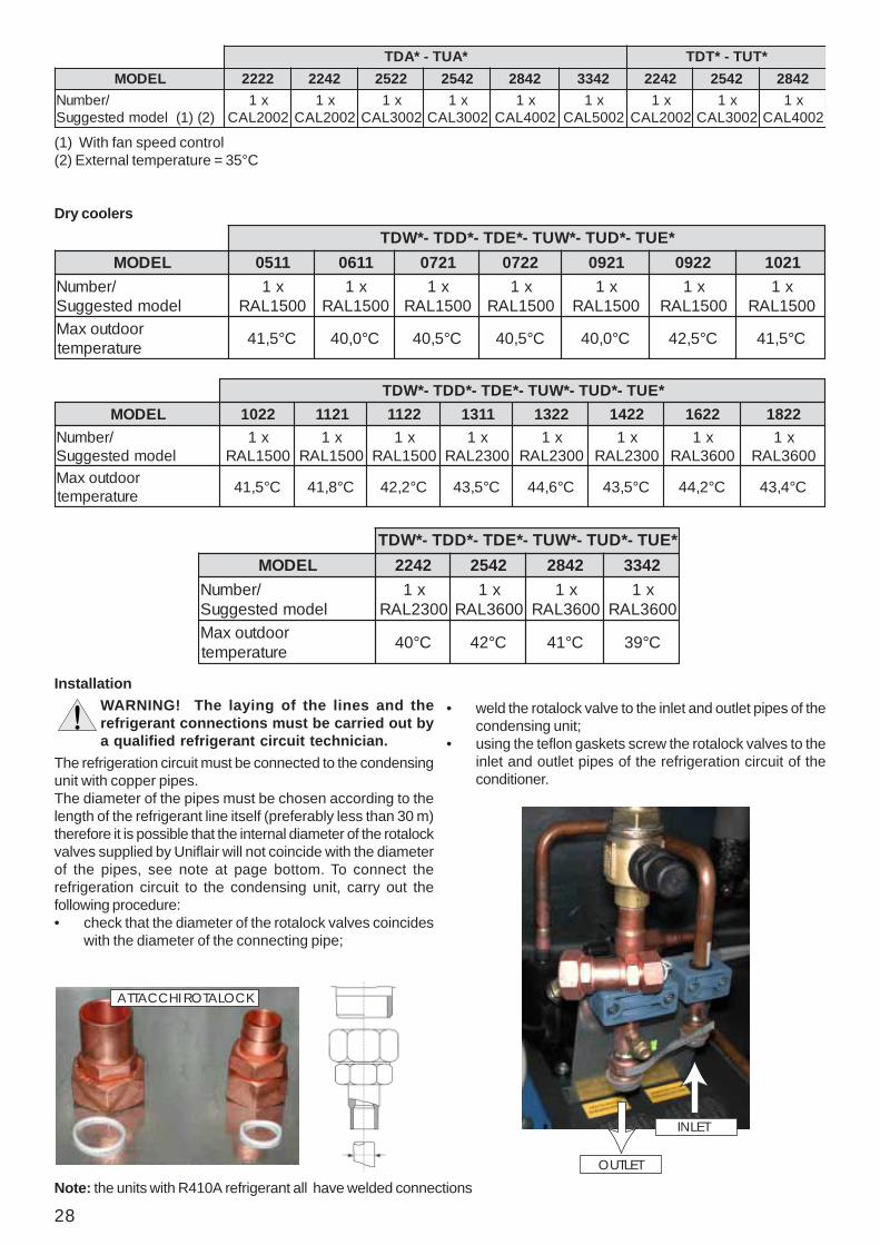
InstallationWARNING! The laying of the lines and therefrigerant connections must be carried out bya qualified refrigerant circuit technician.
The refrigeration circuit must be connected to the condensingunit with copper pipes.The diameter of the pipes must be chosen according to thelength of the refrigerant line itself (preferably less than 30 m)therefore it is possible that the internal diameter of the rotalockvalves supplied by Uniflair will not coincide with the diameterof the pipes, see note at page bottom. To connect therefrigeration circuit to the condensing unit, carry out thefollowing procedure:• check that the diameter of the rotalock valves coincides
with the diameter of the connecting pipe;
INLET
OUTLET
• weld the rotalock valve to the inlet and outlet pipes of thecondensing unit;
• using the teflon gaskets screw the rotalock valves to theinlet and outlet pipes of the refrigeration circuit of theconditioner.
ATTACCHI ROTALOCK
(1) With fan speed control(2) External temperature = 35°C
Dry coolers*EUT-*DUT-*WUT-*EDT-*DDT-*WDT
LEDOM 1150 1160 1270 2270 1290 2290 1201/rebmuN
ledomdetsegguSx1
0051LARx1
0051LARx1
0051LARx1
0051LARx1
0051LARx1
0051LARx1
0051LARroodtuoxaM
erutarepmet C°5,14 C°0,04 C°5,04 C°5,04 C°0,04 C°5,24 C°5,14
*EUT-*DUT-*WUT-*EDT-*DDT-*WDTLEDOM 2201 1211 2211 1131 2231 2241 2261 2281
/rebmuNledomdetsegguS
x10051LAR
x10051LAR
x10051LAR
x10032LAR
x10032LAR
x10032LAR
x10063LAR
x10063LAR
roodtuoxaMerutarepmet C°5,14 C°8,14 C°2,24 C°5,34 C°6,44 C°5,34 C°2,44 C°4,34
Note: the units with R410A refrigerant all have welded connections
*AUT-*ADT *TUT-*TDTLEDOM 2222 2422 2252 2452 2482 2433 2422 2452 2482
/rebmuN)2()1(ledomdetsegguS
x12002LAC
x12002LAC
x12003LAC
x12003LAC
x12004LAC
x12005LAC
x12002LAC
x12003LAC
x12004LAC
*EUT-*DUT-*WUT-*EDT-*DDT-*WDTLEDOM 2422 2452 2482 2433
/rebmuNledomdetsegguS
x10032LAR
x10063LAR
x10063LAR
x10063LAR
roodtuoxaMerutarepmet C°04 C°24 C°14 C°93
29
Evacuation of the refrigeration circuit and charging of refrigerantWARNING! The charging and maintenance of the refrigeration circuit must only be carried out by aqualified hydraulic technician.
The refrigeration circuit is pre-charged with nitrogen.To load the refrigerant, carry out the following procedure:
R22• open any shut-off valves present in the machine to ensure
that all of the components will be evacuated;• connect a pump to empty the schrader connections
efficiently, or to the 1/4" SAE connections present onthe intake and delivery sides of the compressors;
• connect the refrigerant cylinder to the loadingconnections;
• create a vacuum within the lines while maintaining thepressure below 100 Pa absolute (0,7 mm Hg) for a longtime in order to evacuate the air as well as any traces ofhumidity. It is preferable that the vacuum is reachedslowly and maintained for a long period of time;
• wait for a build up period of 100 seconds and check thatthe pressure has not exceeded 200 Pa absolute.Generally, in the case of suspicion of strong hydration ofthe circuit or an extremely extensive system, it will benecessary to break the vacuum with anhydrous nitrogenand then repeat the evacuation procedure as described;
• break the vacuum by performing a preload from the R22coolant cylinder;
• after having started the compressor, slowly complete theloading phase until the pressure within the lines has beenstabilised and the gaseous bubbles have disappearedfrom the flow sight glass;
• the loading process must be controlled in environmentalconditions with a delivery pressure of approximately 18bar (equivalent to a saturated temperature of 48 °C); inthe case of units with ON/OFF condensation controls,avoid switching the condenser fan on and off, which maypartially obstruct the intake surface. It is wise to checkthat the sub-cooling of the liquid at the entry of thethermostatic valve is between 3 and 5 °C below thecondensation temperature read on the scale of thepressure gauge and that the overheating of the vapour atthe exit of the evaporator is equal to 5-8 °C.
R407C - R410A• open any shut-off valves present in the machine to ensure
that all of the components will be evacuated;• connect a pump to empty the schrader connections
efficiently, or to the 1/4" SAE connections present onthe intake and delivery sides of the compressors;
• connect the refrigerant cylinder to the loadingconnections;
• create a vacuum within the lines whilst maintaining thepressure below 10 Pa absolute (0,07 mm Hg) for a longtime in order to evacuate the air as well as any trace ofhumidity. It is preferable that the vacuum is reachedslowly and maintained for a long period of time;
• wait for a build up period of 100 seconds and check thatthe pressure has not exceeded 200 Pa absolute.Generally, in the case of suspicion of strong hydration ofthe circuit or an extremely extensive system, it will benecessary to break the vacuum with anhydrous nitrogenand then repeat the evacuation procedure as described;
• break the vacuum by performing a preload in liquid phasefrom the R407C and R410A coolant cylinder;
• after having started the compressor, slowly complete theloading phase until the pressure within the lines has beenstabilised and the gaseous bubbles have disappearedfrom the flow sight glass;
• the loading process must be controlled in environmental conditions with a delivery pressure of approximately 18
bar (equivalent to a dew temperature of 48 °C and a bubbletemperature of 43 °C); in the case of units with ON/OFFcondensation controls, avoid switching the condenserfan on and off, which may partially obstruct the intakesurface. It is wise to check that the sub-cooling of theliquid at the entry of the thermostatic valve is between 3and 5 °C below the condensation temperature read onthe scale of the pressure gauge and that the overheatingof the vapour at the exit of the evaporator is equal toapproximately 5-8 °C.
Type of oil recommended with COPELAND compressors
Type of oil recommended with MANEUROP compressors
Type of oil recommended with SANYO compressors
Type of oil recommended with Scrolltech HCJ 072-HLJ 083 compressors
)liolareniM(22R SG3osinuS 23FWocaxeT MKshcuF)EOP(C704R cc22citcrALAEliboM S23LRETARAKMEICI
)liolareniM(22R 23OSI/lareniM-P061poruenaM)EOP(C704R ZS061poruenaM)EOP(A014R ZS061poruenaM
)liolareniM(22R T65-YAS)EVP(C704R S86VF)EVP(A014R S86VF
)EVP(A014R D8CVFEVPenhpaD

30
Connection for water cooled unitsWARNING! The laying of the lines and hydraulicconnections must only be carried out by aqualified plumber.
WARNING! The chilled water must contain apercentage of ethylene glycol (of the passivetype, which is therefore not corrosive) accordingto the minimal external temperature predicted(see the table below).
If the water temperature falls to below the dew point of the airconditioner, isolate the piping with closed cell material (e.g.:Armaflex or equivalent) to avoid condensation; the isolationmust allow the accessibility of the valves and the three piecejoints. Seal the piping holes through the base of the conditionerto avoid a bypass of air.
WARNING! The water cooled pressure must notbe above 6 bar.
locylgenelyhtefoegatnecreP %01 %02 %03 %04 %05
erutarepmetgnizeerF C°4- C°01- C°71- C°52- C°73-
If the temperature of the chilled water is not checked it mayfall to under 25°C, therefore it is necessary to use apressostatic valve (available as an optional) for eachcondenser; in this case the pressure of the supply must notbe less then 200 kPa (2 bar).
WARNING! Do not use chilled water with anevaporating tower because the condensers willquickly become encrusted with limescale.
The condenser must be connected to the chilled waterdistribution network, paying attention to the direction of thewater inlet and outlet.The condensers are supplied by water pumped in a closedcircuit and chilled by external refrigerators; check that thesection of piping and the characteristics of the circulationpump are suitable: an insufficient flow of water can have anegative effect on the capacity of the conditioner.The chilled water temperature must be checked to ensurethat it does not fall to below 25°C, preferably according tothe plan indicated in the figure.The microprocessor control system is predisposed formeasuring the temperature of the water using probes (A)and modulating the servomotor of the valve (B) or by drivingthe fans (C) of the external refrigerators.
11501160
1270129012011211123111411241
22702290220122112231224122612281
222224222252245224822433
telniresnednocretaW "1 "4/1.1 "4/1.1x2 "4/1.1x2
resnednocretaWteltuo "1 "4/1.1 "4/1.1x2 "4/1.1x2
Table of condenser fitting dimensions
Once the connections have been made to the hydraulic circuit,the system can be filled.
B
C
A
≥ 25 °C
31
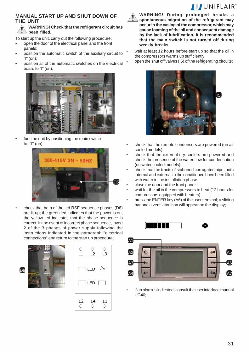
MANUAL START UP AND SHUT DOWN OFTHE UNIT
WARNING! Check that the refrigerant circuit hasbeen filled.
To start up the unit, carry out the following procedure:• open the door of the electrical panel and the front panels;• position the automatic switch of the auxiliary circuit to
"I" (on);• position all of the automatic switches on the electrical
board to "I" (on);
• fuel the unit by positioning the main switch to "I" (on);
D5
• check that both of the led RSF sequence phases (D8)are lit up; the green led indicates that the power is on,the yellow led indicates that the phase sequence iscorrect. In the event of incorrect phase sequence, invert2 of the 3 phases of power supply following theinstructions indicated in the paragraph "electricalconnections" and return to the start up procedure;
D8
L1 L2
LED
LED
L3
12 14 11
WARNING! During prolonged breaks aspontaneous migration of the refrigerant mayoccur in the casing of the compressor, which maycause foaming of the oil and consequent damageby the lack of lubrification. It is recommendedthat the main switch is not turned off duringweekly breaks.
• wait at least 12 hours before start up so that the oil inthe compressors warms up sufficiently;
• open the shut off valves (I5) of the refrigerating circuits;
A2
A3
A4
A5
A6
A7
A1
• check that the remote condensers are powered (on aircooled models);
• check that the external dry coolers are powered andcheck the presence of the water flow for condensation(on water cooled models);
• check that the tracts of siphoned corrugated pipe, bothinternal and external to the conditioner, have been filledwith water in the installation phase;
• close the door and the front panels;• wait for the oil in the compressors to heat (12 hours for
compressors equipped with heaters);• press the ENTER key (A6) of the user terminal; a sliding
bar and a ventilator icon will appear on the display;
• if an alarm is indicated, consult the user interface manualUG40;
I5

32
Selecting the power supply of the fansWARNING! Before establishing the electricalconnection, make sure that the power supply isoff. Also ensure that it is not possible toreconnect the power during the operation.
WARNING! In the case of a unit with ducts, theload loss from the exhaust duct must be less than100 Pa.
In the following table the voltage levels for each model workingin the standard version are given.
HOW TO ADJUST FAN SPEEDIn the TD*R and TU*R units, the speed of the fan rotation canbe varied by using the ATR transformer (F1).
OFF
To shut down the unit carry out the following procedure:WARNING! During prolonged breaks aspontaneous migration of the refrigerant mayoccur in the casing of the compressor, which maycause foaming of the oil and consequent damagebecause of the lack of lubrification. It isrecommended that the main switch is not turnedoff during weekly breaks.
• on the first screen of the user terminal, press keys A5or A7 until the SWITCH OFF UNIT screen appears;
• press the ENTER key to confirm;• the following icons will appear
Press the ENTER to confirm
SETTING AND ADJUSTMENT To obtain the required prevalence of the implant, it is possibleto vary the voltage by selecting one of the following levels:Models 0511-0611140V -160V -180V -190 - 200V -210V -220V -230VModels 0721-1822230V - 250V - 260V - 270V - 280V - 290V - 300V - 310V -320V - 340V - 360V - 380V - 400V.Models 2222 - 2242 - 2522 - 2542 - 2842 - 3342 : 150V -180V - 200V - 230V - 240V - 260V - 280V - 300V - 320V -340V - 360V - 380V - 400V.In the following table the maximum pressure available(expressed in Pa) for each voltage level of the transformer isindicated. The values are given for the maximum air flow(expressed in m3/h).
F1
tinunoisnapxetceridgnisnednocretawdnariA:RW*T-RA*TC704R:tnaregirfeR
aP02 4UE 5UE tsoPgnitaeh
tsoPgnitaeh
5UE+egatlovylppusrewoP
]V[ ]V[ ]V[ ]V[A1160-A1150 081 081 081 091
-A2270-A1270A1201-A2290A1290
A2201-062 062 062 072
-A2211-A1211A2231-A1231 062 062 062 072
-A2261-A2241A2281 072 072 072 082
A2422-A2222 032 032 042 042A2452-A2252 042 042 062 062A2433-A2482 062 062 062 082
tinunoisnapxetceridgnisnednocretawdnariA:RW*T-RA*TA014R:tnaregirfeR
aP02 4UE 5UE tsoPgnitaeh
tsoPgnitaeh
5UE+A1160-A1150 081 081 081 091
-A2270-A1270A1201-A2290A1290
A2201-062 062 062 072
-A2211-A1211A2231-A1231 052 062 062 072
-A2261-A2241A2281 072 072 072 082
-A2422-A2222A2452-A2252 032 042 042 042
A2482 042 042 042 062A2433 042 062 062 062
ledoM RW*T-RA*T1160-1150
RW*T-RA*T1160-1150
m[wolfriA 3 ]h/ 0475 0475tnaregirfeR C704R A014RylppusrewoP
egatlov]V[ ]aP[ ]aP[041 - -061 02 02081 44 44091 17 17002 101 101012 731 731022 671 671032 691 691
SEIRES RW*T-RA*T RW*T-RA*T
ledoM2270-12702290-12902201-1201
2211-12112231-1231
224122612281
2270-12702290-12902201-1201
2211-12112231-1231
224122612281
tnaregirfeR C704R A014Rm[wolfriA 3 ]h/ 0818 01711 00651 0818 05611 0475
ylppusrewoPegatlov
]V[ ]aP[ ]aP[ ]aP[ ]aP[ ]aP[ ]aP[032 - - - - - -052 - - - - 02 -062 81 02 - 02 52 -072 42 83 02 73 55 02082 94 56 63 26 38 63092 67 79 56 98 311 56003 101 521 421 411 241 421013 721 451 521 341 371 521023 251 481 351 661 002 351043 871 822 691 402 542 691063 922 782 652 552 503 652083 233 643 513 703 363 513004 963 334 304 983 754 304

33
After having selected the voltage level, carry out theconnection in the following way:• with the unit turned off, open the front panels and the
door of the electrical panel and the internal protectionpanels;
• select the supply voltage by positioning the main switchto "0" (D5);
• Follow the diagrams displayed below and refer to thewiring diagram enclosed to connect the two electric wiresfound on the fan, or on the connector block, to thecorresponding terminals on the autotransformer
ATR1 ATR2
ATR1 ATR2
ATR1 ATR2
ATR1 ATR2
ATR1 ATR2
ATR1 ATR2
ATR1 ATR2
ATR1 ATR2
ATR1 ATR2
ATR1 ATR2
ATR1 ATR2
ATR1 ATR2
ATR1 ATR2
MODELSda 721 a 1822
MODELSda 2222 a 3342
MODELS 0511-0611
SEIRES RW*T-RA*T RW*T-RA*TledoM 2422-2222 2452-2252 2482 2433 2422-2222 2452-2252 2482 2433
tnaregirfeR C704R A014Rm[wolfriA 3 ]h/ 00022 00032 00532 00532 00022 00032 00532 00532
ylppusrewoPegatlov
]V[ ]aP[ ]aP[ ]aP[ ]aP[ ]aP[ ]aP[ ]aP[ ]aP[051 - - - - - - - -081 - - - - - - - -002 - - - - - - - -032 - - - - 02 - - -042 02 - - - 45 02 - -062 321 02 02 - 541 111 02 -082 171 031 56 02 391 551 88 02003 312 071 201 66 632 791 921 89023 152 802 531 101 572 532 361 431043 582 042 661 331 903 562 591 561063 413 862 591 261 833 592 222 591083 723 492 542 781 263 023 592 812004 543 003 772 452 963 723 503 982
34
MODELS WITH A PHASE CONTROL VOLTAGE REGULATORTo reach the head required by the system for conditioners with fans carrying a CE marking, the input voltage percentage canbe adjusted from the user terminal (A).To select the voltage percentage to be applied, carry outthe following procedures:• on the user terminal press the PRG button;• using the UP or DOWN key select SERVICE MENU and confirm using the ENTER key;• enter the password (see the envelope attached to the manual);• using the UP or DOWN key select HARDWARE SETTING and confirm using the ENTER key;• using the UP or DOWN key select EVAPORATING FAN and confirm using the ENTER key;• set the amount and confirm using the ENTER key.In the following table the maximum pressure available (expressed in Pa) for each voltage level of the transformer isindicated. The values are given for the maximum air flow (expressed in m3/h).
tinunoisnapxetceridgnisnednocretawdnariA:VW*T-VA*TC704R:tnaregirfeRaP02
aP02 4UE 5UE tsoPgnitaeh
tsoPgnitaeh
5UE+egatlovylppusrewoP
]%[ ]%[ ]%[ ]%[A1160-A1150 95 06 06 16
A1290-A2270-A1270A2201-A1201-A2290 96 07 07 17
-A1231-A2211-A1211A2231 36 56 56 76
A2281-A2261-A2241 17 27 37 47A2422-A2222 46 56 56 66A2452-A2252 66 86 86 96
A2482 86 96 96 07A2433 96 07 17 27
tinunoisnapxetceridgnisnednocretawdnariA:VW*T-VA*TA014R:tnaregirfeRaP02
aP02 4UE 5UE tsoPgnitaeh
tsoPgnitaeh
5UE+egatlovylppusrewoP
]%[ ]%[ ]%[ ]%[A1160-A1150 85 95 95 06
A1290-A2270-A1270A2201-A1201-A2290 86 96 96 07
-A1231-A2211-A1211A2231 16 36 26 46
A2281-A2261-A2241 07 17 17 27A2422-A2222 26 36 36 46A2452-A2252 56 66 66 76
A2482 66 76 76 96A2433 76 96 96 96
ledoM VW*T-VA*T1160-1150
VW*T-VA*T1160-1150
m[wolfriA 3 ]h/ 0475 0475tnaregirfeR C704R A014R
egatlovylppusrewoP]%[ ]aP[ ]aP[
05 - -
55 - -
95 02 -
06 55 02
56 351 521
07 532 812
57 333 892
08 593 583
58 384 554
09 545 525
59 826 395
001 286 066
SEIRES RW*T-RA*T RW*T-RA*T
ledoM2270-12702290-12902201-1201
2211-12112231-1231
224122612281
2270-12702290-12902201-1201
2211-12112231-1231
224122612281
tnaregirfeR C704R A014Rm[wolfriA 3 ]h/ 0228 01711 00651 0228 02321 0475
ylppusrewoPegatlov
]%[ ]aP[ ]aP[ ]aP[ ]aP[ ]aP[ ]aP[05 - - - - - -55 - - - - - -06 - - - - - -56 - 54 - - 07 -07 04 021 01 36 541 0157 031 002 78 041 512 7808 022 282 281 732 003 28158 523 463 072 833 583 07209 214 054 073 024 574 07359 215 555 574 335 775 574001 746 786 406 766 707 406
SEIRES RW*T-RA*T RW*T-RA*TledoM 2422-2222 2452-2252 2482 2433 2422-2222 2452-2252 2482 2433
tnaregirfeR C704R A014Rm[wolfriA 3 ]h/ 00022 00032 00532 00532 00022 00032 00532 00532
ylppusrewoPegatlov
]%[ ]aP[ ]aP[ ]aP[ ]aP[ ]aP[ ]aP[ ]aP[ ]aP[55 - - - - - - - -06 - - - - - - - -56 01 - - - 02 - - -07 08 03 - - 09 05 52 -57 061 511 79 56 071 041 021 8908 842 091 181 061 062 032 702 58158 533 092 072 842 153 023 503 48209 034 083 073 053 044 014 004 87359 045 094 564 044 555 025 294 074001 407 076 156 826 827 796 086 266
35
Maximum and minimum water temperaturesThe maximum and minimum water temperatures for chilledwater circuits and for hot water re-heat circuits are: 5°C ÷90°C.The accepted maximum amount of ethylene glycol is 50%.
Setting the pressostatic valve (optional onchilled water cooled models only)The pressostatic valve, by controlling the water flow, preventsthe condensing pressure falling too low and at the same timeminimises water consumption. When necessary, set thepressostatic valve by turning the regulation knob (the pressureincreases when turning it clockwise) until the condensationpressure stabilizes to recommended* checking the pressurewith a gauge fitted to the pressure tapping of the compressordischarge valve.
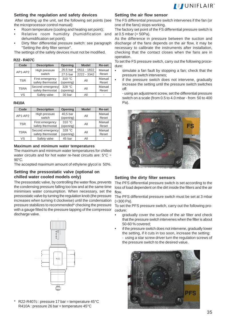
Setting the air flow sensorThe FS differential pressure switch intervenes if the fan (orone of the fans) stops working.The factory set point of the FS differential pressure switch isat 0.5 mbar (= 50Pa).As the difference in pressure between the suction anddischarge of the fans depends on the air flow, it may benecessary to calibrate the instruments after installation,checking that the contact closes when the fans are inoperation.To set the FS pressure switch, carry out the following proce-dure:• simulate a fan fault by stopping a fan; check that the
pressure switch intervenes;• if the pressure switch does not intervene, gradually
increase the setting until the pressure switch switchesoff:- using an adjustment screw, set the differential pressureswitch on a scale (from 0.5 to 4.0 mbar - from 50 to 400Pa).
Setting the dirty filter sensorsThe PFS differential pressure switch is set according to theloss of load dependent on the dirt inside the filters and the airflow.The PFS differential pressure switch must be set at 3 mbar(=300 Pa).To set the PFS pressure switch, carry out the following pro-cedure:• gradually cover the surface of the air filter and check
that the pressure switch intervenes when the filter is about50-60 % covered;
• if the pressure switch does not intervene, gradually lowerthe setting, if it cuts in too soon, increase the setting:- using a star screw driver turn the regulation screws ofthe pressure switch to the desired value.
Setting the regulation and safety devices After starting up the unit, set the following set points (seethe microprocessor control manual):• Room temperature (cooling and heating set point);• Relative room humidity (humidification and
dehumidification set point);• Dirty filter differential pressure switch: see paragraph
"Setting the dirty filter sensor".The settings of the safety devices must not be modified.
R22 - R407C
R410A
edoC noitpircseD gninepO ledoM tes-eR
2PA-1PA erusserphgiHhctiws
rab5.62rab5.72
2281-11502433-2222
launaMteseR
RST ycnegremetsriFtatsomrehtytefas
C°013)gninepo( llA launaM
teseR
ARST ycnegremednoceStatsomrehtytefas
C°823)gninepo( llA launaM
teseRSV evlavytefaS rab03 llA -
edoC noitpircseD gninepO ledoM tes-eR
2PA-1PA erusserphgiHhctiws
rab5,04)gninepo( llA launaM
teseR
RST ycnegremetsriFtatsomrehtytefas
C°013)gninepo( llA launaM
teseR
ARST ycnegremednoceStatsomrehtytefas
C°823)gninepo( llA launaM
teseRSV evlavytefaS rab54 llA -
* R22-R407c : pressure 17 bar = temperature 45°CR410A : pressure 26 bar = temperature 45°C

36
MAINTANENCEThree-monthly checksCarry out the following checks every three months:• check the power supply;• check the alarm status;• check the working pressures and temperatures;• check the correct operation of the local/remote controls;• check the air filters, cleaning and replacing them if
necessary;• check the efficiency of the condensing drain;• check the steam cylinder is clean, replacing it if
necessary;• check and clean if necessary the condensing coil.
Six-monthly checksCarry out the following checks every six months:• repeat these checks on a three-monthly basis;• check and clean if necessary the cooling coil;• check the operation of the humidifier (if present).
Annual checksCarry out the following checks every year:• repeat these checks on a six-monthly basis;• check the varnish and the nuts and bolts;• check the hinges, rabbets and gaskets;• check the cables and wiring;• tighten the terminal blocks;• check and reset if necessary the safety device settings
(pressure switches, thermostats, protection devices);• check the operation of the post heating electrical heaters• check the fittings, operation and absorption of the
evaporating fan/s;• check the fittings, operation and absorption of the
compressor/s;• check and if necessary replace the seal of the refrigerant
circuit/s and tighten the joints and connections of theunit;
• check and top up if necessary the refrigerant gas and/oroil;
• check and if necessary reset the regulation devicessetting;
• check and if necessary replace the seal of the hydrauliccircuits/s and tighten the unit couplings;
• check the fittings and operation of the condensing fan/s;• check and reset if necessary the condensing speed
setting.
Checks to be performed every sixty months• Check and if necessary replace the gas filters;• check and if necessary replace the compressor oil.
Cleaning and repalcing the filtersModels TD. 2222 ÷ 3342To clean and replace the filters carry out the followingprocedures:• remove the front cover of the filters by turning
anticlockwise the panels screws;
• remember the direction of the air flow indicated on thelabel of each filter and draw the filters;
• clean them using a blast of compressed air or replacethem;
• clean them using a blast of compressed air or replacethem;
• mount the front cover of the filters.
37
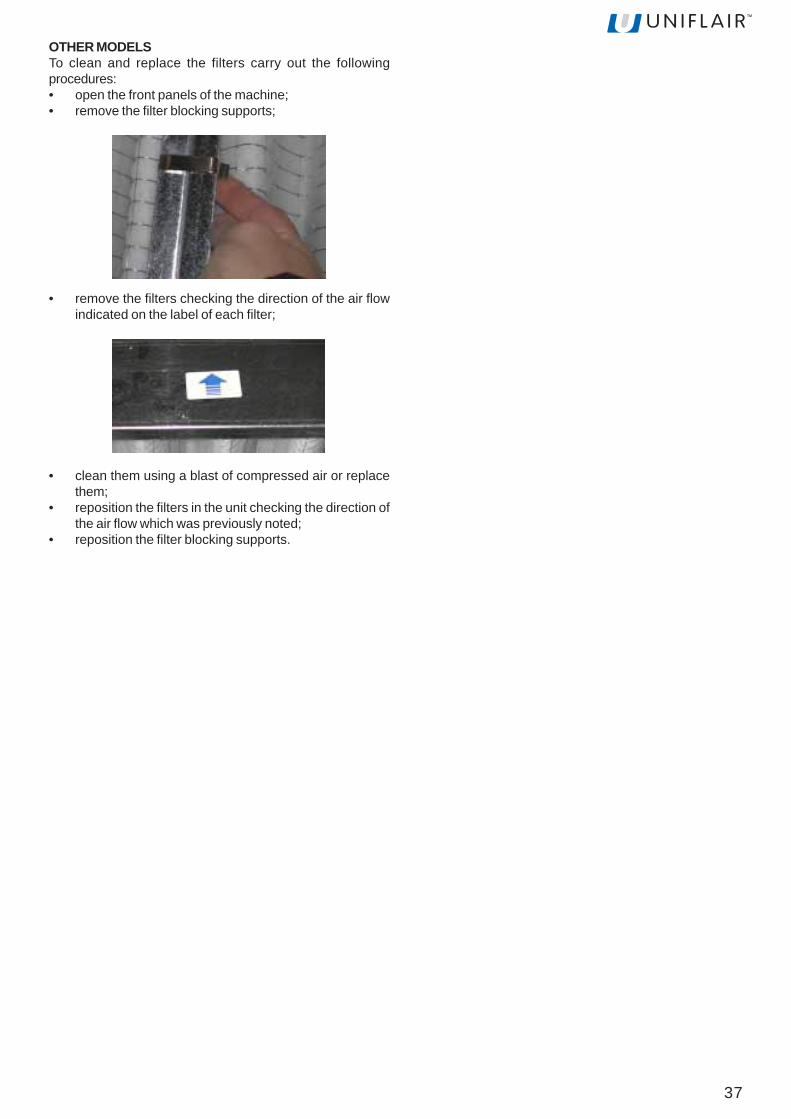
OTHER MODELSTo clean and replace the filters carry out the followingprocedures:• open the front panels of the machine;• remove the filter blocking supports;
• remove the filters checking the direction of the air flowindicated on the label of each filter;
• clean them using a blast of compressed air or replacethem;
• reposition the filters in the unit checking the direction ofthe air flow which was previously noted;
• reposition the filter blocking supports.

38
MELBORP ESUACELBISSOP NOITCAEVITCERROC/KCEHC
MOOREHTOOTSIERUTAREPMET
HGIH
lenaplortnocehtnosgnittesretemarapehT)A.tcerroctonera launamnoitcurtsnilenaplortnoceeS
.tnesbarowolsiwolfriaehT)B ."WOLFRIATNESBA/FOKCAL"eeS
.gnikrowtonsirosneserutarepmetehT)C lortnocehtdnasnoitcennoclacirtceleehtkcehC.noitarugifnoc
.detcepxenahtrehgihsidaollamrehtehT)D .daollamrehts'moorehtkcehC
.gnikrowtonsievlavyaw-eerhtehT)E
rotomovresehtfosnoitcennoclacirtceleehtkcehC.evlav
lortnoclaunamehtfosnaemybevlavehtnepO.bonk
.etnanoiznufnoneivertaalovlaV)E ehttahtkcehc;ylppusretawdellihcehtkcehC.nepoerasevlavffo-tuhs
.wolfretawdellihctneiciffusninasierehT)F .noitnufretawdellihcehtkcehC
.hgihootsierutarepmetretawdellihcehT)G T'NOD/T'NSEOD)S(ROSSERPMOCEHT"eeS."KROW
lortnocetipsedgnikrowton)s(rosserpmocehT)Hllac
T'NOD/T'NSEOD)S(ROSSERPMOCEHT"eeS."KROW
ERUTAREPMETMOORWOLOOT
toneralortnocehtnosgnittesretemarapehT)Atcerroc .launamlortnocrossecorporcimehteeS
cirttcleehtotylppusrewoptneiciffusnisierehT)Bgnikrowtonerasretaehehtrosretaeh
sitnemelegnitaehehtfoMIehttahtkcehC)1.demra
ehtfotiucricgnideefcirtceleehtkcehC)2.sretaeh
dnaesuacehtevomer,mralaretaehasierehtfI)3.tatsomrehtytefasehttes-er
.gnikrowtonsiliocretawtohehT)C.erutarepmetdnayticapacretawtohehtkcehC)1ees(evlavnoitalugerehtfonoitcnufehtkcehC)2
.)rotomovresdnaevlav
gnirudgnikrowtonsiliocsagtohehT)D.taeh-erhtiwnoitacifidimuhed
.noitcnufevlavyaw3sagtohehtkcehC)1gnivresrosserpmocehtfonoitcnufehtkcehC)2
)S(ROSSERPMOCEHT"eeS.taeh-ereht."KROWT'NOD/T'NSEOD
tiucricretawdellihcehtfoevlavyaweerhtehT)E.nepodekcolbsi
dnabonklortnoclaunamehtgnisuevlavehtesolC.rotomovresehtecalper
MELBORP ESUACELBISSOP NOITCAEVITCERROC/KCEHC
TONSEODTINUEHTTRATS
.lenaplacirtceles'tinuehtotylppusrewopoN)A ehtnohctiwsniamtinuehtdnanosirewopehttahtkcehC.desolcsilenaplacirtcele
.stiucricyrailixuaehtotrewopoN)BXUAehtnorekaerbtiucriccitamotuaMIehttahtkcehC)1
.tessitiucric.draobniamehtnoesufehtkcehC)2
.tinuehttratstonseodlenaplortnocehT)C detacolyltcerrocerasrotcennoclenaplortnocehttahtkcehC.stekcosriehtni
TroubleshootingTroubleshooting is made easier by the indications on the control panel display: when an alarm signal is displayed, consultthe control panel instruction manual. If necessary, call the nearest Service Centre describing the nature of the fault and itspossible cause displayed on the control.
TEMPERATURE CONTROL

39
MELBORP ESUACELBISSOP NOITCAEVITCERROC/KCEHC
OOTYTIDIMUHMOORHGIH
lenaplortnocehtnosgnittesretemarapehT)A.tcerroctonera .launamnoitcurtsnilenaplortnoceeS
.detcepxenehtrehgihsidaoltnetalehT)B dnasnoitidnocriahserf,daoltnetalehtkcehC.noitartlifnirialanretxe;emulov
gnirudnoitcnuftonseodrosserpmocehT)C.noitacifidimuhed
T'NOD/T'NSEOD)S(ROSSERPMOCEHT"eeS."KROW
ehtrofdlocyltneiciffustonsiretawdellihcehT)Ddnagnivasygreneni(noitcnufnoitacifidimuhed
.)stinuloocniwt
litnuerutarepmetretawdellihcehtrewoL.liocehtfoecafrusehtnotneserpsietasnednoc
OOTYTIDIMUHMOORWOL
lenaplortnocehtnosgnittesretemarapehT)A.tcerroctonera
lortnocees(sgnittesytidimuhmoorehtkcehC.)launamnoitcurtsnilenap
.detcepxenahtrewolsidaoltnetalehT)B .taehtnetalfoytitnauqehtkcehC
.krowt'nseodreifidimuhehT)C
.erusserpylppusretawehtkcehC)1metsyslortnoclaunamehtfonoitcnufehtkcehC)2
lenapees(puorgnoitcudorpmaetsehtfodna.)launamnoitcurtsni
.krowtonseodmetsyslortnocehT)Dkcehc;launamnoitcurtsnilenaplortnocehteeS
krowsrosnesro/dnalenaplortnocehttaht.ylreporp
MELBORP ESUACELBISSOP NOITCAEVITCERROC/KCEHC
RIAWOLROTNESBAWOLF
.snafehtotrewoponsierehT)A snafehtotylppusrewopehtkcehC
mralaretlifytrid(deggolcerasretlifriaehT)B.)delbane
naelcdnaegdirtracehtfotuotsudehtekahS)1sitifiretlifehtecalpeR.renaelcmuucavahtiw
.dekcolbyletelpmoc
retlifytridehtfognittestcerrocehtkcehC)2.SFPhctiwserusserp
.detcurtsbosiwolfriaehT)Cneveton,detcurtsbotonsiwolfriaehttahtkcehC
.yllaitrap
.senevretninoitcetorplamreht'snafehT)D.sgnidniwrotomnafehtfoecnatsiserehtkcehC.noitprosbadnaegatlovehterusaemnehttes-eR
devrucdrawkcabhtiwstinuR*UT,R*DTnI()EsisnafehtotylppusrewopehT.)snafedalb
.tneiciffusni
.snafehtotegatlovylppusrewopehtegnahC.)tnemtsujdadnagnitteS'.hpargarapeeS(
.hgihootsierusserptuptuonoitubirtsidriaehT)F gniliec,stcud(noitubirtsiderusserpriaehtkcehC.)sellirg,munelproolfro
MELBORP ESUACELBISSOP NOITCAEVITCERROC/KCEHC
YTEFASRETAEHCIRTCELESENEVRETNITATSOMREHT
.wolfriatneiciffusnisierehT)A ."WOLFRIATNESBA/FOKCAL"eeS
detpurretnisieriwnoitcennoctatsomrehtehT)B ytefasehtneewtebnoitcennocehtkcehC.metsyslortnocehtdnatatsomreht
.ytluafsitatsomrehtehT)C .tatsomrehtehtecalpeR
HUMIDITY CONTROL
FANS
ELECTRIC HEATER
40
MELBORP ESUACELBISSOP NOITCAEVITCERROC/KCEHC
ROSSERPMOCHGIHERUSSERPEGRAHCSID
ehtnisagroriaelbasnednoc-nonsierehT)A;ssalgthgiswolfehtniselbbubhtiw,tiucrictnaregirfer
.gnilooc-busevissecxe.egrahcerdnatiucrictnaregirferehtetaucavE
siregnahcxetaehetomerehtotwolfriaehT)B.mrawootrotneiciffusni
ehtninoitceridnoitatordnanoitareponafehtkcehC)1.regnahcxetaehetomer
yrassecenfidnaytridsiregnahcxeehtfieesotkcehC)2,tsud,sdees,repap,sevael(lairetamgnitcurtsboynaevomer
;hsurbaroriadesserpmocfotsalbahtiw).ctewolfriaehtnisnoitcurtsborofkcehctinulanretxeehtnI)3
.riagniloocehtfonoitalucricerehtnidnanihtiwsiriagniloocehtfoerutarepmetehttahtkcehC)4
.stimildennalpeht
rotneiciffusnisiresnednocehtotwolfretawehT)C.mrawoot
dnaerusserp,wolfretawresnednocehtkcehC)1.metsysretawtiucricdesolcehtnierutarepmet
citatsosserpehtfonoitcnufdnagnittesehtkcehC)2.evlavnoitaluger
eht;tiucricehtnitnaregirferhcumootsierehT)DtnaregirferehT.dedoolfyllaitrapsiresnednocteltuoresnednocehttahgihootsigniloocbus
.tiucricehtmorftnaregirferemosevomeR
desolcyllaitraperasevlavegrahcsidehT)E .sevlavehtfogninepoehtkcehC
PA ERUSSERPHGIHSENEVRETNIHCTIWS
egrahcsidrosserpmochgih()erusserp
tonsimetsyslortnocerusserpgnisnednocehT)A.yltneiciffegninoitcnuf
ehtfodnaresnednocehtfonoitcnufnafehtkcehC)1.snafytluafehtecalperrotes-er;noitcetorpevitalerdeepsnafehtfonoitcnufdnagnittesehtkcehC)2
.resnednocetomerehtforotalugerhgihootsierusserpegrahcsidmetsysehT)B ."ERUSSERPEGRAHCSIDROSSERPMOCHGIH"eeS
ROSSERPMOCWOLERUSSERPEGRAHCSID
tonsimetsyslortnocerusserpgnisnednocehT)A.)launamlenaplortnocees(yltneiciffegninoitcnuf
nafresnednocehtfonoitcnufdnagnittesehtkcehC.rotalugerdeepsrohctiwserusserp
ootrohgihootsiresnednocehtotwolfretawehT)B.dloc
;erutarepmetdnawolfretawresnednocehtkcehC)1gnitalugererusserpehtfonoitcnufdnagnittesehtkcehC)2
.)dettiffi(evlavretawehtlortnocotevlavgnitalugererusserpatiF)3
.erusserpgnisnednocehtotgnidroccaerusserp
.wolootsierusserpnoitcusehT)C ."ERUSSERPNOITCUSROSSERPMOCWOL"eeS
ROSSERPMOCHGIHERUSSERPNOITCUS
.hgihootsidaollamrehtehT)A revofoesacnikcehc;daollamrehts'moorehtkcehCfosnoitidnocdnawolfriaehtkcehc,noitacifidimuhed
.noitartlifnirialanretxeehtkcehc,rialanretxe.hgihootsierusserpegrahcsidehT)B ."ERUSSERPEGRAHCSIDROSSERPMOCHGIH"eeS
.tiucricehtnitnaregirferfoegrahcrevonasierehT)C .tiucricehtmorftnaregirferemosevomeR
ehtottnaregirferdiuqilfonruterasierehT)Dekatnirosserpmoc
sievlavcitatsomrehtehtfognittestaehrepusehttahtkcehC.tcerroc
REFRIGERANT CIRCUIT
41
MELBORP ESUACELBISSOP NOITCAEVITCERROC/KCEHC
NOITCUSROSSERPMOCWOLgnizeerfelbissopdna(ERUSSERP
)liocehtfo
.wolootsierutarepmetmoorehT)A ."WOLOOTERUTAREPMETMOOR"eeS.tnesbasirowolootsiwolfriaehT)B ."WOLFRIAWOL"eeS
yletelpmoctonsievlavdionelosenildiuqilehT)C.nepo .gninepoevlavehtkcehC
.detcurtsbosiretliftnaregirferehT)D .retliftnaregirferehtkcehC
rodetarbilacyltcerrocnisievlavcitatsomrehtehT)E.evitcefed
citatsomrehtehtfognittestaehrepusehtkcehCstitsoltonsahblubrosnesehttahtkcehc;evlav
.detalusnidnadexif,denoitisopllewsidnaegrahc
.egrahctnaregirfertneiciffusninasierehT)Ftadiuqiltnaregirferehtfognilooc-busehtkcehCynaeraerehtfieesotkcehc;teltuoresnednoceht
.tinuehtegrahc-erdnaskael
MELBORP ESUACELBISSOP NOITCAEVITCERROC/KCEHC
)S(ROSSERPMOCEHTKROWT'NOD/T'NSEOD
.denevretnisahnoitcetorptiucrictrohsehT)A
ehtfoesuacehtkcehcdnahctiwscitamotuaehttes-eRehtkcehc,rosserpmocehtgnitrats-ererofeB.tiucrictrohs
rotomrosserpmocehtfoytiunitnocdnaecnatsiser.sgnidniw
.gnikrowtonsirotcatnocehT)B .liocrotcatnocehtdnastcatnocehtkcehC
S'ROSSERPMOCEHTNOITCETORPLANRETNI
SENEVRETNI
.gnissimsiesahpA)A.sgnidniwrotomrosserpmocehtfoecnatsiserehtkcehC
tnerrucdnaegatlovehterusaem,gnittes-erretfA.sesahpeerhtehtfonoitprosba
.dedaolrevosirotomehT)B dennalpehtnihtiwsetarepoerusserptinuehttahtkcehC.stimil
.wolootrohgihootsiegatlovylppusrewopehT)C dna%01-nihtiwsiegatlovehttahtkcehC.eulavlanimonehtfo%01+
.dekcolbsirotorehT)D .rosserpmocehtecalpeR
YSIONSIROSSERPMOCEHT .degamadsirosserpmocehT)A ehtecalperotredroniertneCecivreStseraenehtllaC.rosserpmoc
.rosserpmocehtotnruterdiuqilsierehT)B .evlavcitatsomrehtehtfonoitcnufdnagnittesehtkcehC
COMPRESSORS

42
LEONARDO EVOLUTION - CHILLED WATERTechnical characteristicsCHILLED WATER UNITS WITH BACKWARD CURVED BLADE FANS
RCUT-RCDTledoM A0021 A0071 A0002 A0052thgieH mm 0691 0691 0691 0691
htdiW mm 0131 1271 2712 2712htpeD mm 568 568 568 568
thgieW gk 413 593 344 854)*(wolfretawdellihC h/l 0157 0669 05911 09051)**(wolfretawdellihC h/l 0735 0436 0428 05601egatlovylppuscirtcelE V zH05/N+hp3/V004
RCUT-RCDTledoM B006 B007 A006 A007 A0001thgieH mm 0691 0691 0691 0691 0691
htdiW mm 0101 0101 0101 0101 0131htpeD mm 057 057 057 057 568
thgieW gk 012 022 012 022 603)*(wolfretawdellihC h/l 0804 6464 0804 6464 0585)**(wolfretawdellihC h/l 0382 0423 0382 0423 0844egatlovylppuscirtcelE V zH05/N+hp3/V004 zH05/N+hp3/V004
(*) Based on 24°C@50% air temperature, ESP=20Pa, chilled water 7/12°C, ethylene glycol 0%(**) Based on 24°C@50% air temperature, ESP=20Pa, chilled water 10/15°C, ethylene glycol 0%
RCUT-RCDTledoM 0072 0043 0004 )RCDTylno(0034thgieH mm 0691 0691 0691 0712
htdiW mm 0712 0852 0852 0852htpeD mm 568 568 568 568
)1()noisrevetelpmoC(thgieW gk 205 027 047 028)*(wolfretawdellihC h/l 45861 97291 85612 64182)**(wolfretawdellihC h/l 71821 71641 95061 31802egatlovylppuscirtcelE V zH05/N+hp3/V004
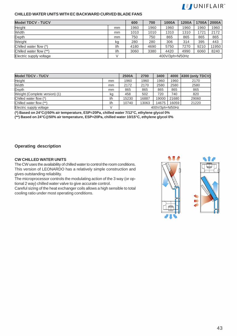
43
CW CHILLED WATER UNITSThe CW uses the availability of chilled water to control the room conditions.This version of LEONARDO has a relatively simple construction andgives outstanding reliability.The microprocessor controls the modulating action of the 3 way (or op-tional 2 way) chilled water valve to give accurate control.Careful sizing of the heat exchanger coils allows a high sensible to totalcooling ratio under most operating conditions.
Operating description
(*) Based on 24°C@50% air temperature, ESP=20Pa, chilled water 7/12°C, ethylene glycol 0%(**) Based on 24°C@50% air temperature, ESP=20Pa, chilled water 10/15°C, ethylene glycol 0%
VCUT-VCDTledoM A0052 0072 0043 0004 )VCDTylno(0034thgieH mm 0691 0691 0691 0691 0712
htdiW mm 2712 0712 0852 0852 0852htpeD mm 568 568 568 568 568
)1()noisrevetelpmoC(thgieW gk 854 205 027 047 028)*(wolfretawdellihC h/l 03251 78861 00091 08612 06092)**(wolfretawdellihC h/l 04701 36031 57641 95061 02212egatlovylppuscirtcelE V zH05/N+hp3/V004
VCUT-VCDTledoM 006 007 A0001 A0021 A0071 A0002thgieH mm 0691 0691 0691 0691 0691 0691
htdiW mm 0101 0101 0131 0131 1271 2712htpeD mm 057 057 568 568 568 568
thgieW gk 082 082 603 413 593 344)*(wolfretawdellihC h/l 0814 0964 0575 0727 0129 05911)**(wolfretawdellihC h/l 0603 0833 0244 0994 0606 0428egatlovylppuscirtcelE V zH05/N+hp3/V004
CHILLED WATER UNITS WITH EC BACKWARD CURVED BLADE FANS
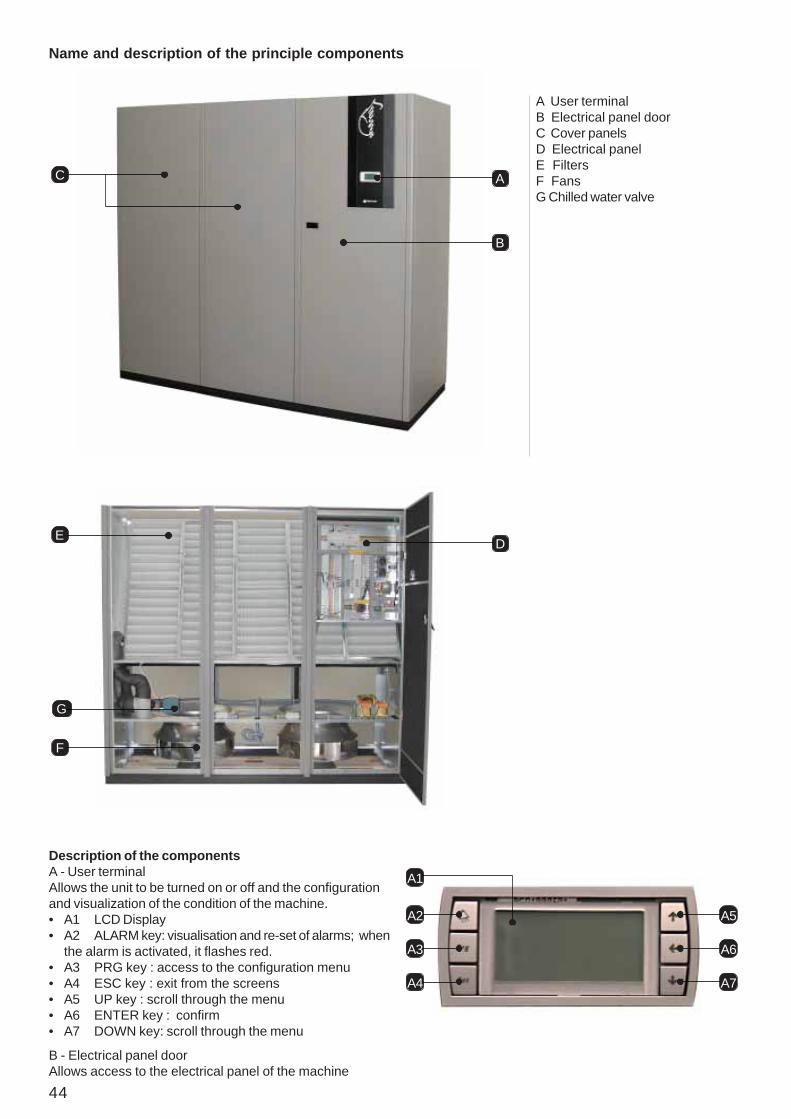
44
Name and description of the principle components
A
D
B
C
E
F
G
Description of the componentsA - User terminalAllows the unit to be turned on or off and the configurationand visualization of the condition of the machine.• A1 LCD Display• A2 ALARM key: visualisation and re-set of alarms; when
the alarm is activated, it flashes red.• A3 PRG key : access to the configuration menu• A4 ESC key : exit from the screens• A5 UP key : scroll through the menu• A6 ENTER key : confirm• A7 DOWN key: scroll through the menu
A User terminalB Electrical panel doorC Cover panelsD Electrical panelE FiltersF FansG Chilled water valve
A2
A3
A4
A5
A6
A7
A1
B - Electrical panel doorAllows access to the electrical panel of the machine

45
G - Chilled water valve• G1 Servomotor• G2 Manual control knob• G3 Valve stem
H - Cooling coil
C - Cover panelsAllow access to the internal components of the machine.
E - FiltersFilter the air released into the environment
D5
D1
D2
D3
D6
D4
F - FansAllow the diffusion of air into the room• F1 ATR Transformer: allows the setting of the fan rotation
speed of the TD*R and TU*R units.
D - Electric panel• D1 Magnetothermic
- auxiliary- heater (optional)- humidifier (optional)- fans
• D2 Interface board• D3 Dirty filter sensor• D4 Air flow sensor• D5 Main switch• D6 Terminal board• D7A Input/output electrical supply cables• D7B Input/output electrical auxiliary cables• D7C Input/output signal cables (RS485 and/or LAN)
E
H1
FF1
G1
G2
G
G3
D7A
D7B
D7C

46
Checks to be made on deliveryWARNING! Dispose of the packaging inappropriate collection points.
The Leonardo Evolution units are packaged in wooden cratesor anchored to a pallet and covered in cardboard.Check that the delivery is complete and inform the carrier ofany damage to the unit which may be attributed too carelessor inappropriate transportation. Check, in particular, anyeventual damage to the panel in which the user terminal ismounted.Lifting and moving the unit must be carried out by amechanical lifter.The following must be container within the packaging:• The Leonardo Evolution unit;• Leonardo Use and Installation Manual;• Leonardo unit electrical diagrams;• Leonardo unit cooling circuit diagrams;• Leonardo unit installation diagrams;• List of spare parts;• CE declaration with a list of the European standards to
which the machine must conform;• guarantee conditions
Unloading the unitTo unload the unit from the pallet, carry out the following pro-cedure:• move the pallet as near as possible to where the unit is
to be installed;• use a ramp to avoid any damage to the unit during
unloading;
• remove the blocking screws which fix the unit to thepallet;
• carefully push the unit along the ramp until it reachesthe floor.
Characteristics of the installation areaWARNING! The unit must be installed internallyand protected from adverse conditions.
The unit is predisposed to be installed on raised access flooringusing mounting frames or appropriate floor stands suppliedon request from Uniflair. However, the upflow units (upwardsair flow) with air intake through the rear or front can be installedalso on floors which are not raised.The area of installation must have the following characteristics:• make sure to leave a 700mm clearence (distance D) in
front of the unit once it has been fitted. Check that airintake and discharge connections are not blocked in anyway, not even partially;
• a horizontal and even floor;• the electrical energy distribution system has been
produced in respect of CEI standards, suitable for thecharacteristics of the unit;
• a cold water distribution implant (if a humidifier is to beinstalled);
• implant for connection to the condensing unit;• external air outlet (if a fresh air intake is to be installed);• for the refrigerating gas drain see paragraph "Connection
to gas drain";• drainage system.
WARNING! The preparation of the installationarea must be carried out as indicated in theinstallation drawing attached to the machinedocumentation.
Positioning of the unitWARNING! If the surface where the unit is placedis not even and horizontal there, is a risk of anoverflow from the condensation tray.
Installation on raised access flooringInstallation on raised access flooring occurs by means of amounting frame. The frame enables the installation of theunit before the raised floor is installed, increased absorptionof noise and vibrations and the facilitation of connecting pipesand cables.The up flow models (upwards air flow) with rear or frontal airintake may be installed without using the mounting frame.
D
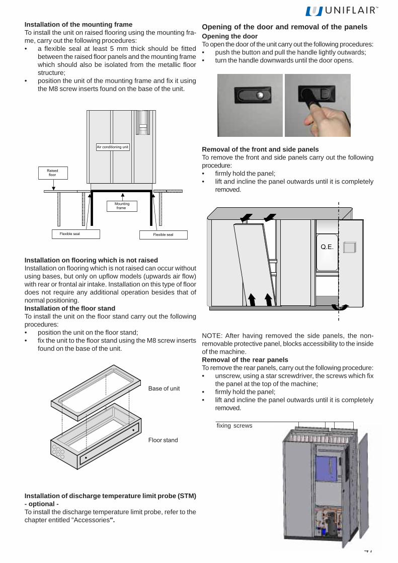
47
Installation of the mounting frameTo install the unit on raised flooring using the mounting fra-me, carry out the following procedures:• a flexible seal at least 5 mm thick should be fitted
between the raised floor panels and the mounting framewhich should also be isolated from the metallic floorstructure;
• position the unit of the mounting frame and fix it usingthe M8 screw inserts found on the base of the unit.
Installation on flooring which is not raisedInstallation on flooring which is not raised can occur withoutusing bases, but only on upflow models (upwards air flow)with rear or frontal air intake. Installation on this type of floordoes not require any additional operation besides that ofnormal positioning.Installation of the floor standTo install the unit on the floor stand carry out the followingprocedures:• position the unit on the floor stand;• fix the unit to the floor stand using the M8 screw inserts
found on the base of the unit.
Opening of the door and removal of the panelsOpening the doorTo open the door of the unit carry out the following procedures:• push the button and pull the handle lightly outwards;• turn the handle downwards until the door opens.
Removal of the front and side panelsTo remove the front and side panels carry out the followingprocedure:• firmly hold the panel;• lift and incline the panel outwards until it is completely
removed.
Q.E.
Installation of discharge temperature limit probe (STM)- optional -To install the discharge temperature limit probe, refer to thechapter entitled "Accessories".
NOTE: After having removed the side panels, the non-removable protective panel, blocks accessibility to the insideof the machine.Removal of the rear panelsTo remove the rear panels, carry out the following procedure:• unscrew, using a star screwdriver, the screws which fix
the panel at the top of the machine;• firmly hold the panel;• lift and incline the panel outwards until it is completely
removed.
fixing screws
Flexible seal Flexible seal
Mountingframe
Raisedfloor
Air conditioning unit
basamento condizionatore
zoccolo unità
Base of unit
Floor stand

48
Internal protection panelsThe technical compartment, the electric heaters and theautotransformer fans are protected by internal protectionpanels for safety reasons and to allow the opening of theexternal panels without triggering the unit's safety alarms. Inthe figures below the different types of internal protectionpanels are shown on various types of machines.
Before removing the internal protection panels,disconnect the power supply by turning the main isolatingswitch D5 to position "O", then wait until the fans stop andthe electrical heaters cool down.
MODELS TUCR -TUCV: 600B, 600A, 700A, 700B, 1000A,1200A, 1700A, 2000A, 2500A, 2700A
MODELS TUCR - TUCV: 3400A, 4000A
MODELS TDCR - TDCV: 600A, 600B, 700A, 700B, 1000A,1200A, 1700A, 2000A, 2500A, 2700A
MODELS TDCR 3400A - TDCR 4000A - TDCV 3400A - TDCV4000A - TDCV 4300A
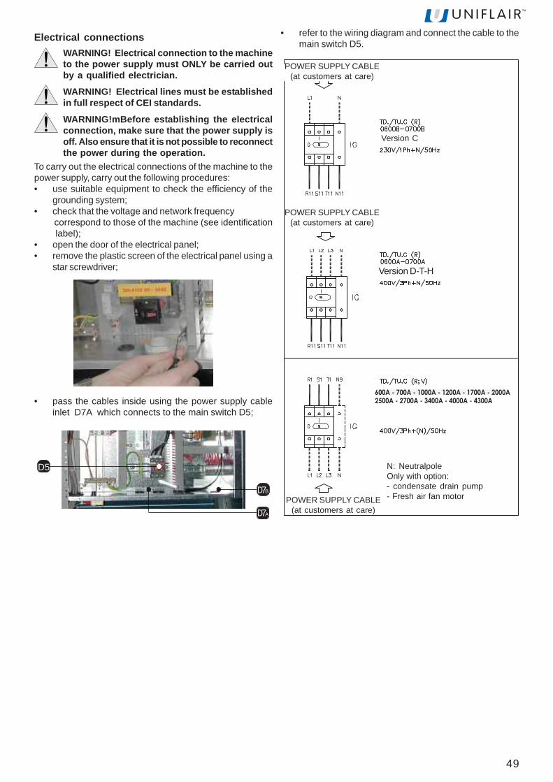
49
2500A - 2700A - 3400A - 4000A - 4300A
600A - 700A - 1000A - 1200A - 1700A - 2000A
Electrical connectionsWARNING! Electrical connection to the machineto the power supply must ONLY be carried outby a qualified electrician.
WARNING! Electrical lines must be establishedin full respect of CEI standards.
WARNING!mBefore establishing the electricalconnection, make sure that the power supply isoff. Also ensure that it is not possible to reconnectthe power during the operation.
To carry out the electrical connections of the machine to thepower supply, carry out the following procedures:• use suitable equipment to check the efficiency of the
grounding system;• check that the voltage and network frequency correspond to those of the machine (see identification label);• open the door of the electrical panel;• remove the plastic screen of the electrical panel using a
star screwdriver;
D7A
D7B
D5
POWER SUPPLY CABLE(at customers at care)
POWER SUPPLY CABLE(at customers at care)
Version C
Version D-T-H
POWER SUPPLY CABLE(at customers at care)
N: NeutralpoleOnly with option:- condensate drain pump- Fresh air fan motor
• pass the cables inside using the power supply cableinlet D7A which connects to the main switch D5;
• refer to the wiring diagram and connect the cable to themain switch D5.

50
Once the connections have been made, pour water into thecondensate collection tray until the siphons have been filled.
U7
U4
Connection to the water drainCondensation water drains from the tray bymeans of a flexible siphoned tube, which is fitted in the unit.If the unit is fitted with a humidifier, the condensate drain trayand the humidifier drain connection must be connected tothe drains of the building.Direct connection to the drains of the buildingConnect the drainage tube of the unit to the drains of thebuilding using a rubber or plastic tube with an internal diameterof 25 mm.The external drainage tube must be siphoned in order to avoidunpleasant odours. Maintain a minimum slope of 1%downstream of the siphon.
D7A
D7B
To connect the auxiliary connections to the terminal boardcarry out the following procedures:• pass the cables through the power supply cable inlet
D7B;
DIGITAL CONFIGURABLE INPUTS
Terminal board 51-20- User- ON - OFF Remote- Flooding sensor (SAS)Terminal board 52-20- User- ON-OFF Remote- Fire-smoke (SFF)Terminal board 50-20- User- ON-OFF Remote- Tools (ATA-BTA-AUA-BUA)Terminal board 60-20- Summer-Winter remote- Water flow meter
D5
20
20
20
20
50
51
52
60
Connection of the humidifier (additional fitting) and tothe storm sewer system
WARNING! The water discharged from the humidifieris at a very high temperature. The drainage tube hasto withstand high temperatures (at least 100°C) andmust be kept away from electrical cables.
Connect the drainage tube of the unit to the collection tray(U4) of the humidifier.Connect the drainage tube of the humidifier (U7) to the drainsof the building using a rubber or plastic tube, which is resistantto high temperatures (minimum 100 °C) with an internaldiameter of 32 mm.
The external drainage tube must be siphoned to avoidunpleasant odours and an overflow of the water from the trayof the humidifier.
Drain
%Siphon
Minimum slope
• refer to the wiring diagram and carry out the connectionto the terminal board.
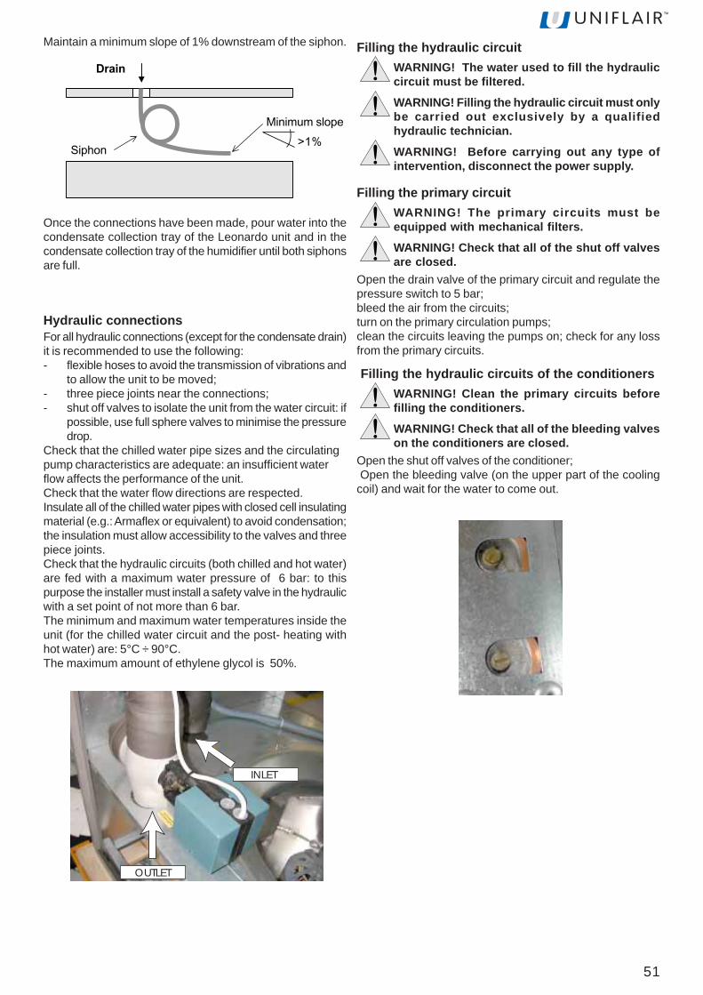
51
Once the connections have been made, pour water into thecondensate collection tray of the Leonardo unit and in thecondensate collection tray of the humidifier until both siphonsare full.
OUTLET
INLET
Filling the hydraulic circuitWARNING! The water used to fill the hydrauliccircuit must be filtered.
WARNING! Filling the hydraulic circuit must onlybe carried out exclusively by a qualifiedhydraulic technician.
WARNING! Before carrying out any type ofintervention, disconnect the power supply.
Filling the primary circuitWARNING! The primary circuits must beequipped with mechanical filters.
WARNING! Check that all of the shut off valvesare closed.
Open the drain valve of the primary circuit and regulate thepressure switch to 5 bar;bleed the air from the circuits;turn on the primary circulation pumps;clean the circuits leaving the pumps on; check for any lossfrom the primary circuits.
Filling the hydraulic circuits of the conditionersWARNING! Clean the primary circuits beforefilling the conditioners.
WARNING! Check that all of the bleeding valveson the conditioners are closed.
Open the shut off valves of the conditioner; Open the bleeding valve (on the upper part of the coolingcoil) and wait for the water to come out.
Hydraulic connectionsFor all hydraulic connections (except for the condensate drain)it is recommended to use the following:- flexible hoses to avoid the transmission of vibrations and
to allow the unit to be moved;- three piece joints near the connections;- shut off valves to isolate the unit from the water circuit: if
possible, use full sphere valves to minimise the pressuredrop.
Check that the chilled water pipe sizes and the circulatingpump characteristics are adequate: an insufficient waterflow affects the performance of the unit.Check that the water flow directions are respected.Insulate all of the chilled water pipes with closed cell insulatingmaterial (e.g.: Armaflex or equivalent) to avoid condensation;the insulation must allow accessibility to the valves and threepiece joints.Check that the hydraulic circuits (both chilled and hot water)are fed with a maximum water pressure of 6 bar: to thispurpose the installer must install a safety valve in the hydraulicwith a set point of not more than 6 bar.The minimum and maximum water temperatures inside theunit (for the chilled water circuit and the post- heating withhot water) are: 5°C ÷ 90°C.The maximum amount of ethylene glycol is 50%.
Maintain a minimum slope of 1% downstream of the siphon.
Drain
%Siphon
Minimum slope

52
MANUAL START UP AND SHUT DOWN OFTHE UNIT
WARNING! Check that the refrigerant circuit hasbeen filled
To start up the unit carry out the following procedure:• open the door of the electrical panel and the front panels;• position the automatic switch of the auxiliary circuit to
"I" (on);• position all of the automatic switches on the electrical
board to "I" (on);
• fuel the unit by positioning the main switch to "I" (on);
D5
• check that the tracts of corrugated pipe with siphon,both internal and external to the conditioner, have beenfilled with water in the installation phase;
• close the door and the front panels;• press the ENTER key (A6) of the user terminal; a sliding
bar and a ventilator icon will appear on the display;
A2
A3
A4
A5
A6
A7
A1
• if an alarm is indicated, consult the user interface manual UG40;• check the rotation direction of the fans; the correct
direction is indicated with an arrow which is on the fanitself. If the rotation is in the wrong direction, invert twoof the three power supply phases following theinstructions indicated in the paragraph entitled "Electricalconnections" and then restart the start-up procedure
To turn the unit off, carry out the following procedure:• on the first screen of the user terminal, press the A5 or
A7 buttons until the SWITCH OFF UNIT screen appears;• press the ENTER button to confirm;• the following icons will appear
Press the ENTER button to confirm
OFF
53
To obtain the required prevalence of the implant, it is possibleto vary the voltage by selecting one of the following levels,suitable for models from 0600 to 0700:140V -160V -180V -190V -200V -210V -220V -230Vmodels from 1000 to 2700:230V - 250V - 260V - 270V - 280V - 290V - 300V - 310V -320V - 340V - 360V - 380V - 400V.models 3400 - 4000 - 4300: 150V - 180V - 200V - 230V - 240V - 260V - 280V - 300V -320V - 340V - 360V - 380V - 400V.In the following table the maximum pressure available(expressed in Pa) for each voltage level of the transformer isindicated. The values are given for the maximum air flow(expressed in m3/h).
SETTING AND ADJUSTMENTSelecting the power supply of the fans
WARNING! Before establishing the electricalconnection, make sure that the power supply isoff. Also ensure that it is not possible toreconnect the power during the operation.
WARNING! In the case of a unit with ducts, theload loss from the exhaust duct must be less than100 Pa.
In the following table the voltage levels for each model workingin the standard version are given.
HOW TO ADJUST FAN SPEEDIn the TD*R three phase models the rotation speed of thefans be varied by using the ATR transformer (F1).
F1
sledoM V
RCUT-RCDT
0060 0910070 591
0002-0001 0130021 0430071 0620052 0230072 0430043 0820004 0030034 083
0001RCUT/RCDTm[AF 3 ]=h/ 0075 0007 0008 0009 00201 04411V aP
032 921 37 41 - - -052 181 421 56 - - -062 602 051 19 8 - -072 232 571 711 43 - -082 752 102 241 95 - -092 382 622 861 58 - -003 903 252 491 111 - -013 433 872 912 631 - -023 063 303 542 261 02 -043 114 553 692 312 96 -063 264 604 743 462 121 -083 415 754 993 613 271 -004 565 805 054 763 322 02
0060RCUT/RCDTm[AF 3 ]=h/ 0134 0054 0005 0055 0995 0066
% V aP04 241 86 65 02 - - -05 861 931 421 77 32 - -55 081 971 261 111 25 - -06 591 732 712 061 49 52 -07 512 333 903 042 461 48 -08 222 373 743 472 391 801 -09 722 104 473 892 412 621 5001 032 424 693 713 132 041 02
0070RCUT/RCDTm[AF 3 ]=h/ 0824 0054 0005 0055 0606 0056
% V aP04 241 86 45 51 - - -05 861 041 221 57 12 - -55 081 081 061 901 05 - -06 591 832 612 851 29 02 -07 512 533 703 832 261 76 -08 222 573 643 272 191 19 0209 722 304 373 692 212 801 42001 032 724 593 513 822 221 53
54
0002RCUT/RCDTm[AF 3 ]=h/ 00001 00021 00051 08681 00591 01802V aP
032 08 04 - - - -052 041 19 - - - -062 071 021 03 - - -072 002 051 55 - - -082 772 081 19 - - -092 952 712 611 - - -003 982 052 541 - - -013 713 572 671 - - -023 943 533 302 - - -043 093 493 662 02 - -063 944 354 423 511 64 -083 805 215 183 371 601 -004 085 335 044 232 261 02
0052RCUT/RCDTm[AF 3 ]=h/ 00001 00021 00061 08681 00591 07502V aP
032 85 02 - - - -052 711 95 - - - -062 741 98 - - - -072 671 811 - - - -082 502 741 02 - - -092 532 771 06 - - -003 462 602 49 - - -013 492 632 421 - - -023 323 562 351 - - -043 283 423 212 02 - -063 144 383 172 88 02 -083 005 244 033 751 08 -004 975 325 973 502 731 02
0072RCUT/RCDTm[AF 3 ]=h/ 03531 03061 00071 52781 00091 00591 05602V aP
032 - - - - - - -052 22 - - - - - -062 45 - - - - - -072 78 - - - - - -082 911 6 - - - - -092 051 53 - - - - -003 181 36 41 - - - -013 012 19 14 - - - -023 832 811 76 - - - -043 092 861 711 02 4 - -063 833 412 261 46 84 71 -083 083 652 402 501 88 75 -004 814 492 242 241 521 49 02
0043RCUT/RCDTm[AF 3 ]=h/ 00351 00091 00032 77742 00062 00082 02582V aP
051 - - - - - - -081 55 - - - - - -002 131 3 - - - - -032 532 301 - - - - -042 762 431 - - - - -062 723 191 54 - - - -082 183 442 09 02 - - -003 034 192 131 75 5 - -023 374 333 861 19 63 - -043 115 073 202 221 66 - -063 445 204 232 151 49 - -083 175 924 952 871 021 12 -004 295 154 282 102 441 64 02
0021RCUT/RCDTm[AF 3 ]=h/ 0075 0007 0008 0009 00201 04411V aP
032 321 46 3 - - -052 471 511 45 - - -062 002 141 08 - - -072 522 661 501 02 - -082 152 291 131 64 - -092 772 812 751 17 - -003 203 342 281 79 - -013 823 962 802 321 - -023 453 492 432 841 - -043 504 643 582 991 02 -063 654 793 633 152 17 -083 705 844 783 203 221 02004 955 994 934 353 981 65
0071RCUT/RCDTm[AF 3 ]=h/ 0087 0009 00011 02941 00071 08391V aP
032 521 07 - - - -052 481 921 86 - - -062 312 951 09 - - -072 342 881 911 - - -082 272 712 941 - - -092 103 742 871 02 - -003 123 672 802 06 - -013 063 603 732 39 - -023 093 533 762 251 - -043 944 493 623 112 05 -063 705 354 483 072 901 -083 665 215 344 003 861 -004 116 965 305 253 032 02

55
After having selected the voltage level, carry out the connectionin the following way:• with the unit turned off, open the front panels and the door of the electrical panel and the internal protection panels;• select the supply voltage by positioning the main switch to "0" (D5);• Follow the diagrams displayed below and refer to the
wiring diagram enclosed to connect the two electric wiresfound on the fan, or on the connector block, to thecorresponding terminals on the autotransformer
ATR1 ATR2
ATR1 ATR2
ATR1 ATR2
ATR1 ATR2
ATR1 ATR2
ATR1 ATR2
ATR1 ATR2
ATR1 ATR2
ATR1 ATR2
ATR1 ATR2
ATR1 ATR2
ATR1 ATR2
ATR1 ATR2
MODELSfrom1000to 2700
MODELSfrom 3400 to 4300
MODELS from 0600 to 0700
0034RCUT/RCDTm[AF 3 ]=h/ 04951 00091 00032 00252 00562 00572 00182V aP
051 - - - - - - -081 02 - - - - - -002 69 - - - - - -032 002 97 - - - - -042 232 901 - - - - -062 192 561 42 - - - -082 643 612 66 - - - -003 493 262 501 2 - - -023 834 303 041 23 - - -043 674 043 371 16 41 - -063 805 273 202 88 04 - -083 535 993 922 411 66 02 -004 655 124 252 831 19 54 02
0004RCUT/RCDTm[AF 3 ]=h/ 04951 00091 00032 00252 00562 00572 00182V aP
051 - - - - - - -081 02 - - - - - -002 69 - - - - - -032 002 98 - - - - -042 232 021 - - - - -062 292 771 82 - - - -082 643 032 37 - - - -003 593 772 411 02 - - -023 934 913 151 35 - - -043 774 653 581 48 22 - -063 905 883 512 211 94 - -083 635 514 242 931 57 52 -004 722 734 562 261 99 05 02
56
MODELS WITH FANS CARRYING A CE MARKINGTo reach the head required by the system for conditioners with fans carrying a CE marking, the imput voltage percentagecan be adjusted from the user terminal (A).To select the voltage, carry out the following procedure:• on the user terminal press the PRG button;• using the UP or DOWN key select SERVICE MENU and confirm using the ENTER key;• enter the password (see the envelope attached to the manual);• using the UP or DOWN key select HARDWARE SETTING and confirm using the ENTER key;• using the UP or DOWN key select EVAPORATING FAN and confirm using the ENTER key;• set the amount and confirm using the ENTER key.In the following table the maximum pressure available (expressed in Pa) for each voltage level of the transformer is indicated.The values are given for the maximum air flow (expressed in m3/h).
0002VCUT/VCDTm[AF 3 ]=h/ 09011 00021 00041 00061 08681 00612
% V aP05 004 0 - - - - -55 004 06 - - - - -06 004 811 08 - - - -56 004 181 711 - - - -07 004 052 091 57 - - -57 004 533 762 751 95 - -08 004 024 843 242 351 - -58 004 805 234 133 052 22 -09 004 595 125 224 543 031 -59 004 786 416 715 544 042 -001 004 487 427 516 525 523 02
0001VCUT/VCDTm[AF 3 ]=h/ 0075 0007 0008 00001 00011 03811
% V aP05 004 74 - - - - -55 004 501 - - - - -06 004 761 74 - - - -56 004 332 221 4 - - -07 004 403 102 09 - - -57 004 083 382 871 - - -08 004 954 863 962 - - -58 004 345 754 263 57 - -09 004 136 945 754 081 - -59 004 427 346 555 582 49 -001 004 128 147 456 193 402 02
0021VCUT/VCDTm[AF 3 ]=h/ 0095 0007 0008 00001 00011 04711
% V aP05 004 12 - - - - -55 004 18 - - - - -06 004 541 83 - - - -56 004 212 311 - - - -07 004 482 291 97 - - -57 004 163 472 761 - - -08 004 144 953 852 - - -58 004 625 844 153 85 - -09 004 416 045 644 361 - -59 004 707 436 345 862 47 -001 004 408 237 346 473 481 02
0071VCUT/VCDTm[AF 3 ]=h/ 0979 00011 00021 00041 00061 08102
% V aP05 004 02 - - - - -55 004 96 - - - - -06 004 521 55 - - - -56 004 681 021 36 - - -07 004 252 981 531 4 - -57 004 323 462 212 68 - -08 004 004 343 392 171 02 -58 004 184 624 873 062 011 -09 004 865 415 764 253 502 -59 004 066 606 065 644 203 -001 004 757 307 756 555 204 12
006VCUT/VCDTm[AF 3 ]=h/ 0534 0005 0995 0056 0007 0008
% V aP05 004 09 - - - - -55 004 071 08 - - - -06 004 052 071 02 - - -56 004 033 062 721 03 - -07 004 014 043 712 731 05 -87 004 035 084 953 092 251 0208 004 065 305 983 133 502 2758 004 436 375 564 893 723 15109 004 407 356 945 084 114 04259 004 097 827 216 155 374 413001 004 758 397 976 416 345 283
007VCUT/VCDTm[AF 3 ]=h/ 0534 0005 0606 0056 0007 0008
% V aP05 004 08 - - - - -55 004 061 07 - - - -06 004 042 061 01 - - -56 004 023 052 711 02 - -07 004 004 033 702 721 04 -87 004 025 074 943 082 241 0108 004 055 394 973 123 591 2658 004 426 365 554 883 713 14109 004 496 346 935 074 104 03259 004 087 817 206 145 364 403001 004 748 387 966 406 335 273

57
Setting the regulation and safety devicesAfter starting up the conditioner, set the following set points(see Microprocessor Control Manual):• Room temperature (cooling and heating set point);• Relative room humidity (humidification and
dehumidification set point);• Dirty filter differential pressure switch: see paragraph
"Setting the dirty filter sensor".The settings of the safety devices must not be modified.
0043VCUT/VCDTm[AF 3 ]=h/ 00961 00581 00512 57842 00562 00082 05223
% V aP55 004 02 - - - - - -06 004 28 62 - - - - -56 004 841 69 - - - - -07 004 812 961 75 - - - -57 004 592 742 041 - - - -77 004 423 972 471 02 - -08 004 273 823 622 67 - - -38 004 224 973 972 231 64 - -58 004 654 314 513 071 58 - -09 004 445 305 704 662 381 89 -59 004 636 695 202 463 482 002 -001 004 337 396 006 464 583 303 02
0004VCUT/VCDTm[AF 3 ]=h/ 07561 00091 00032 71252 0072 00582 02913
% V aP55 004 02 - - - - - -06 004 08 - - - - - -56 004 641 46 - - - - -07 004 612 931 - - - - -57 004 092 712 85 - - - -97 004 353 282 921 02 - -08 004 963 992 741 93 - - -28 004 814 053 102 59 - - -58 004 254 583 832 331 63 - -09 004 045 574 233 032 531 54 -59 004 236 865 824 923 632 841 -001 004 927 566 725 924 833 252 02
0034VCDTm[AF 3 ]=h/ 00171 00091 00032 71252 00692 00003 02623
% V aP55 004 02 - - - - - -06 004 28 61 - - - - -56 004 941 78 - - - - -07 004 022 261 3 - - - -57 004 592 042 98 - -- - -97 004 853 503 061 65 - -08 004 473 223 871 57 - - -28 004 424 373 232 131 - - -58 004 854 804 962 961 - - -09 004 645 894 363 662 02 - -59 004 936 195 954 563 421 89 -001 004 537 886 855 564 922 402 02
0052VCUT/VCDTm[AF 3 ]=h/ 04501 00021 00041 00061 08681 05312
% V aP05 004 02 - - - - -55 004 08 0 - - - -06 004 041 07 - - - -56 004 202 731 41 - - -07 004 962 502 59 - - -57 004 143 082 571 14 - -08 004 914 733 852 631 - -58 004 105 224 743 432 - -09 004 785 115 844 423 09 -59 004 976 406 345 424 002 -001 004 367 217 126 405 082 02
0072VCUT/VCDTm[AF 3 ]=h/ 05321 00051 00571 16781 00591 00012 02422
% V aP55 004 02 - - - - - -06 004 68 - - - - - -56 004 551 4 - - - - -07 004 922 68 - - - - -57 004 603 171 - - - - -87 004 553 422 05 - - -08 004 883 952 88 - - - -28 004 124 592 621 02 - - -58 004 374 943 481 08 21 - -09 004 265 344 282 181 511 - -59 004 556 935 283 482 912 17 -001 004 257 736 484 783 423 971 02
edoC noitpircseD gninepO laitnereffiD tes-eR
RST tatsomrehtytefaS)snoisrevHdnaT(
C°013)gninepo( - launaM
teser
ARST tatsomrehtytefaS)snoisrevHdnaT(
C°823)gninepo( - launaM
teser
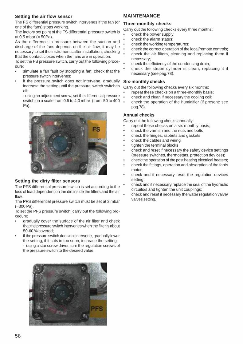
58
Setting the air flow sensorThe FS differential pressure switch intervenes if the fan (orone of the fans) stops working.The factory set point of the FS differential pressure switch isat 0.5 mbar (= 50Pa).As the difference in pressure between the suction anddischarge of the fans depends on the air flow, it may benecessary to set the instruments after installation, checkingthat the contact closes when the fans are in operation.To set the FS pressure switch, carry out the following proce-dure:• simulate a fan fault by stopping a fan; check that the
pressure switch intervenes;• if the pressure switch does not intervene, gradually
increase the setting until the pressure switch switchesoff:- using an adjustment screw, set the differential pressureswitch on a scale from 0.5 to 4.0 mbar (from 50 to 400Pa).
MAINTENANCEThree-monthly checksCarry out the following checks every three months:• check the power supply;• check the alarm status;• check the working temperatures;• check the correct operation of the local/remote controls;• check the air filters, cleaning and replacing them if
necessary;• check the efficiency of the condensing drain;• check the steam cylinder is clean, replacing it if
necessary (see pag.78).
Six-monthly checksCarry out the following checks every six months:• repeat these checks on a three-monthly basis;• check and clean if necessary the cooling coil;• check the operation of the humidifier (if present: see
pag.78).
Annual checksCarry out the following checks annually:• repeat these checks on a six-monthly basis;• check the varnish and the nuts and bolts• check the hinges, rabbets and gaskets• check the cables and wiring• tighten the terminal blocks• check and reset if necessary the safety device settings
(pressure switches, thermostats, protection devices);• check the operation of the post heating electrical heaters;• check the fittings, operation and absorption of the fan/s
motor;• check and if necessary reset the regulation devices
setting;• check and if necessary replace the seal of the hydraulic
circuits/s and tighten the unit couplings;• check and reset if necessary the water regulation valve/
valves setting.
Setting the dirty filter sensorsThe PFS differential pressure switch is set according to theloss of load dependent on the dirt inside the filters and the airflow.The PFS differential pressure switch must be set at 3 mbar(=300 Pa).To set the PFS pressure switch, carry out the following pro-cedure:• gradually cover the surface of the air filter and check
that the pressure switch intervenes when the filter is about50-60 % covered;
• if the pressure switch does not intervene, gradually lowerthe setting, if it cuts in too soon, increase the setting:- using a star screw driver, turn the regulation screws ofthe pressure switch to the desired value.
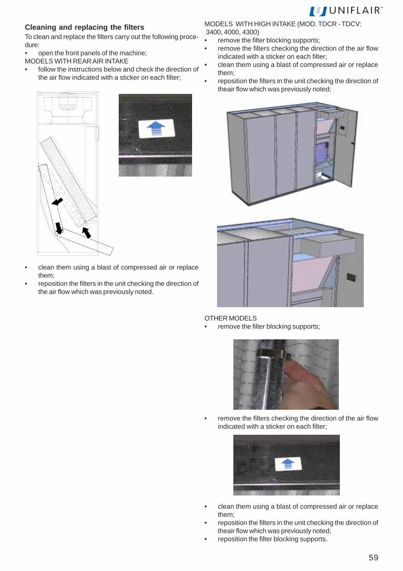
59
Cleaning and replacing the filtersTo clean and replace the filters carry out the following proce-dure:• open the front panels of the machine;MODELS WITH REAR AIR INTAKE• follow the instructions below and check the direction of
the air flow indicated with a sticker on each filter;
• clean them using a blast of compressed air or replacethem;
• reposition the filters in the unit checking the direction ofthe air flow which was previously noted.
MODELS WITH HIGH INTAKE (MOD. TDCR - TDCV: 3400, 4000, 4300)• remove the filter blocking supports;• remove the filters checking the direction of the air flow
indicated with a sticker on each filter;• clean them using a blast of compressed air or replace
them;• reposition the filters in the unit checking the direction of
theair flow which was previously noted;
OTHER MODELS• remove the filter blocking supports;
• remove the filters checking the direction of the air flowindicated with a sticker on each filter;
• clean them using a blast of compressed air or replacethem;
• reposition the filters in the unit checking the direction oftheair flow which was previously noted;
• reposition the filter blocking supports.

60
Servomotor and chilled water valveIf necessary (in the event of a fault in the servomotor or thecontrol system) manually move the valve as described below:• pull the manual control knob (G2);• turn the knob clockwise to lower the valve stem (G3)
(OPEN) and anti-clockwise to raise the valve stem (G3)(CLOSE).
G1
G2
G4
G3
In the 600 and 700 models the following servomotor is installed:
To manually move the valve, use the hexagonal key and screwto open and unscrew to close.
Alternatively, it is possible to remove the servomotor from thebody of the valve and move the valve stem itself.
Servomotor and hot water valveTo manually move the valve by turning the control knobclockwise to open and anti-clockwise to close.
Alternatively, it is possible to remove the servomotor from thebody of the valve and move the valve stem itself.
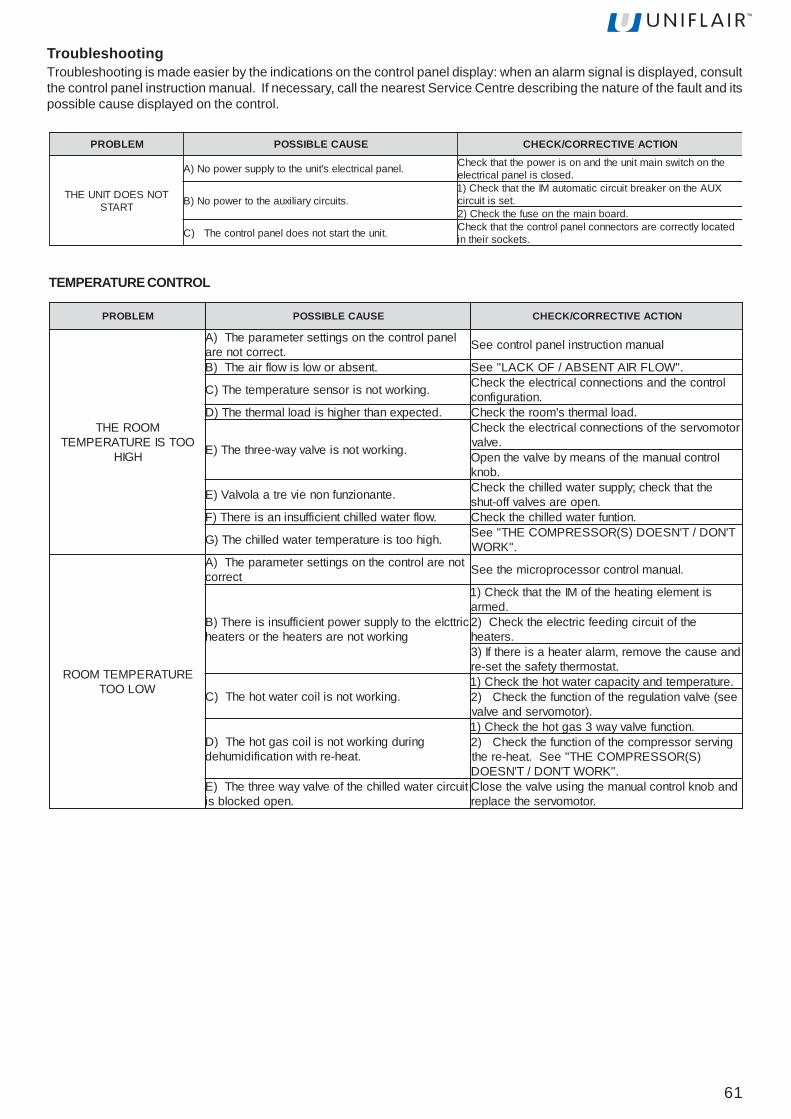
61
MELBORP ESUACELBISSOP NOITCAEVITCERROC/KCEHC
MOOREHTOOTSIERUTAREPMET
HGIH
lenaplortnocehtnosgnittesretemarapehT)A.tcerroctonera launamnoitcurtsnilenaplortnoceeS
.tnesbarowolsiwolfriaehT)B ."WOLFRIATNESBA/FOKCAL"eeS
.gnikrowtonsirosneserutarepmetehT)C lortnocehtdnasnoitcennoclacirtceleehtkcehC.noitarugifnoc
.detcepxenahtrehgihsidaollamrehtehT)D .daollamrehts'moorehtkcehC
.gnikrowtonsievlavyaw-eerhtehT)E
rotomovresehtfosnoitcennoclacirtceleehtkcehC.evlav
lortnoclaunamehtfosnaemybevlavehtnepO.bonk
.etnanoiznufnoneivertaalovlaV)E ehttahtkcehc;ylppusretawdellihcehtkcehC.nepoerasevlavffo-tuhs
.wolfretawdellihctneiciffusninasierehT)F .noitnufretawdellihcehtkcehC
.hgihootsierutarepmetretawdellihcehT)G T'NOD/T'NSEOD)S(ROSSERPMOCEHT"eeS."KROW
ERUTAREPMETMOORWOLOOT
toneralortnocehtnosgnittesretemarapehT)Atcerroc .launamlortnocrossecorporcimehteeS
cirttcleehtotylppusrewoptneiciffusnisierehT)Bgnikrowtonerasretaehehtrosretaeh
sitnemelegnitaehehtfoMIehttahtkcehC)1.demra
ehtfotiucricgnideefcirtceleehtkcehC)2.sretaeh
dnaesuacehtevomer,mralaretaehasierehtfI)3.tatsomrehtytefasehttes-er
.gnikrowtonsiliocretawtohehT)C.erutarepmetdnayticapacretawtohehtkcehC)1ees(evlavnoitalugerehtfonoitcnufehtkcehC)2
.)rotomovresdnaevlav
gnirudgnikrowtonsiliocsagtohehT)D.taeh-erhtiwnoitacifidimuhed
.noitcnufevlavyaw3sagtohehtkcehC)1gnivresrosserpmocehtfonoitcnufehtkcehC)2
)S(ROSSERPMOCEHT"eeS.taeh-ereht."KROWT'NOD/T'NSEOD
tiucricretawdellihcehtfoevlavyaweerhtehT)E.nepodekcolbsi
dnabonklortnoclaunamehtgnisuevlavehtesolC.rotomovresehtecalper
MELBORP ESUACELBISSOP NOITCAEVITCERROC/KCEHC
TONSEODTINUEHTTRATS
.lenaplacirtceles'tinuehtotylppusrewopoN)A ehtnohctiwsniamtinuehtdnanosirewopehttahtkcehC.desolcsilenaplacirtcele
.stiucricyrailixuaehtotrewopoN)BXUAehtnorekaerbtiucriccitamotuaMIehttahtkcehC)1
.tessitiucric.draobniamehtnoesufehtkcehC)2
.tinuehttratstonseodlenaplortnocehT)C detacolyltcerrocerasrotcennoclenaplortnocehttahtkcehC.stekcosriehtni
TroubleshootingTroubleshooting is made easier by the indications on the control panel display: when an alarm signal is displayed, consultthe control panel instruction manual. If necessary, call the nearest Service Centre describing the nature of the fault and itspossible cause displayed on the control.
TEMPERATURE CONTROL
62
MELBORP ESUACELBISSOP NOITCAEVITCERROC/KCEHC
OOTYTIDIMUHMOORHGIH
lenaplortnocehtnosgnittesretemarapehT)A.tcerroctonera .launamnoitcurtsnilenaplortnoceeS
.detcepxenehtrehgihsidaoltnetalehT)B dnasnoitidnocriahserf,daoltnetalehtkcehC.noitartlifnirialanretxe;emulov
.gnittuhstonevlavnoitacifidimuheD)C ehtfoevlavdionelosgnideefehtkcehC.ylreporpgnikrowsitiucricnoitacifidimuhed
.gnikrowtonmetsyslortnoC)D;launamnoitcurtsniresumetsyslortnoC:eeSgnikroweraeborpehtro/dnalenapehtkcehc
.ylreporpehtrofdlocyltneiciffustonsiretawdellihcehT)E
dnagnivasygreneni(noitcnufnoitacifidimuhed.)stinuloocniwt
litnuerutarepmetretawdellihcehtrewoL.liocehtfoecafrusehtnotneserpsietasnednoc
OOTYTIDIMUHMOORWOL
lenaplortnocehtnosgnittesretemarapehT)A.tcerroctonera
lortnocees(sgnittesytidimuhmoorehtkcehC.)launamnoitcurtsnilenap
.detcepxenahtrewolsidaoltnetalehT)B dnasnoitidnocriahserf,daoltnetalehtkcehC.noitartlifnirialanretxe;emulov
.krowt'nseodreifidimuhehT)C
.erusserpylppusretawehtkcehC)1metsyslortnoclaunamehtfonoitcnufehtkcehC)2
lenapees(puorgnoitcudorpmaetsehtfodna.)launamnoitcurtsni
.krowtonseodmetsyslortnocehT)Dkcehc;launamnoitcurtsnilenaplortnocehteeS
krowsrosnesro/dnalenaplortnocehttaht.ylreporp
MELBORP ESUACELBISSOP NOITCAEVITCERROC/KCEHC
RIAWOLROTNESBAWOLF
.snafehtotrewoponsierehT)A snafehtotylppusrewopehtkcehC
mralaretlifytrid(deggolcerasretlifriaehT)B.)delbane
naelcdnaegdirtracehtfotuotsudehtekahS)1sitifiretlifehtecalpeR.renaelcmuucavahtiw
.dekcolbyletelpmoc
retlifytridehtfognittestcerrocehtkcehC)2.SFPhctiwserusserp
.noitceridgnorwehtnignitatorsnaF)C erasnaffikcehcdnasesahptupniesreveRnoitceridtcerrocehtnignitator
.detcurtsbosiwolfriaehT)D "NOITUBIRTSIDRIA"hpargarapkcehC
.senevretninoitcetorplamreht'snafehT)E .sgnidniwrotomnafehtfoecnatsiserehtkcehC.noitprosbadnaegatlovehterusaemnehttes-eR
.yltcerroctestonrotalugerdeepsnaF)F DNATNEMTSUJDADEEPSNAFhpargarapeeS.GNITTESROTALUGERDEEPS
.metsisnoitubirtsidriaehtnissoldaehevissecxE)G
noitubirtsidriaehtfogninoisnemidehtkcehC)1dednepsus,stcud(strapstillasallewsa,metsys
)sellirgria,munelproolf,sgniliecsnafgnivah-sledomRCUTdnaRCDTroF()2
rewopehtegnahc)sedalbdevrucdrawkcabhtiwehtesaercniotredroni,snafehtfoegatlovylppus
.deepsnoitatornaf
MELBORP ESUACELBISSOP NOITCAEVITCERROC/KCEHC
YTEFASRETAEHCIRTCELESENEVRETNITATSOMREHT
.wolfriatneiciffusnisierehT)A ."WOLFRIATNESBA/FOKCAL"eeS
detpurretnisieriwnoitcennoctatsomrehtehT)B ytefasehtneewtebnoitcennocehtkcehC.metsyslortnocehtdnatatsomreht
.ytluafsitatsomrehtehT)C .tatsomrehtehtecalpeR
HUMIDITY CONTROL
FANS
ELECTRIC HEATERS

63
ENERGY SAVING UNIT WITH EC BACKWARD CURVED BLADE FANS
VEUT-VEDTledoM 115 116 127 227 129 229 1201 2201thgieH mm 0691 0691 0691 0691 0691 0691 0691 0691
htdiW mm 0101 0101 0131 0131 0131 0131 0131 0131htpeD mm 057 057 568 568 568 568 568 568
thgieW gk 082 082 034 744 034 744 034 744stiucricgnitaregirferforebmuN 1 1 1 2 1 2 1 2
srosserpmocforebmuN 1 1 2 2 2 2 2 2egatlovylppuscirtcelE V zH05/N+hp3/V004
VEUT-VEDTledoM 1211 2211 1231 2231 2241 2261 2281thgieH mm 0691 0691 0691 0691 0691 0691 0691
htdiW mm 0271 0271 0271 0271 1712 1712 1712htpeD mm 568 568 568 568 568 568 568
thgieW gk 845 955 575 585 896 417 417stiucricgnitaregirferforebmuN 1 2 1 2 2 2 2
srosserpmocforebmuN 2 2 2 2 2 2 2egatlovylppuscirtcelE V zH05/N+hp3/V004
LEONARDO EVOLUTION ENERGY SAVINGTechnical characteristics ENERGY SAVING UNIT WITH BACKWARD CURVED BLADE FANS
REUT-REDTledoM A115 A116 A127 A227 A129 A229 A1201 A2201thgieH mm 0691 0691 0691 0691 0691 0691 0691 0691
htdiW mm 0101 0101 0131 0131 0131 0131 0131 0131htpeD mm 057 057 568 568 568 568 568 568
thgieW gk 082 013 034 744 034 744 034 744stiucricgnitaregirferforebmuN 1 1 1 2 1 2 1 2
srosserpmocforebmuN 1 1 2 2 2 2 2 2egatlovylppuscirtcelE V zH05/N+hp3/V004
REUT-REDTledoM A1211 A2211 A1231 A2231 A2241 A2261 A2281thgieH mm 0691 0691 0691 0691 0691 0691 0691
htdiW mm 0271 0271 0271 0271 1712 1712 1712htpeD mm 568 568 568 568 568 568 568
thgieW gk 845 955 575 585 896 417 417stiucricgnitaregirferforebmuN 1 2 1 2 2 2 2
srosserpmocforebmuN 2 2 2 2 2 2 2egatlovylppuscirtcelE V zH05/N+hp3/V004
REDTledoM 2422 2452 2482thgieH mm 5712 5712 5712
htdiW mm 0852 0852 0852htpeD mm 568 568 568
thgieW gk 699 0201 0211stiucrictnaregirferforebmuN 2 2 2
srosserpmocforebmuN 4 4 4egatlovylppusrewoP V zH05/N+hp3/V004
REUTledoM 2422 2452 2482thgieH mm 0691 0691 0691
htdiW mm 0852 0852 0852htpeD mm 568 568 568
thgieW gk 699 0201 0211stiucrictnaregirferforebmuN 2 2 2
srosserpmocforebmuN 4 4 4egatlovylppusrewoP V zH05/N+hp3/V004

64
Direct expansion operation
VEDTledoM 2422 2452 2482thgieH mm 5712 5712 5712
htdiW mm 0852 0852 0852htpeD mm 568 568 568
thgieW gk 699 0201 0211stiucrictnaregirferforebmuN 2 2 2
srosserpmocforebmuN 4 4 4egatlovylppusrewoP V zH05/N+hp3/V004
VEUTledoM 2422 2452 2482thgieH mm 0691 0691 0691
htdiW mm 0852 0852 0852htpeD mm 568 568 568
thgieW gk 699 0201 0211stiucrictnaregirferforebmuN 2 2 2
srosserpmocforebmuN 4 4 4egatlovylppusrewoP V zH05/N+hp3/V004
ENERGY SAVINGLEONARDO Energy -Saving units represent the ultimate energy savingefficient solution.The operating principle exploits the "free cooling" effect available whenthe outside air temperature is lower than that in the conditioned space.The lower the outside temperature, the greater the energy saving is.The sophisticated microprocessor control manages the operation of theunit automatically in three different situations.In summer, the unit operates as a normal closed circuit glycol cooledsystem (see the "Direct Expansion Operation" diagram). As the externaltemperature falls, the chilled water can be used directly for the free-cooling of the air. In this case the cold water is circulated in the coilinside the unit (see the "Mixed cooling operation" diagram); both theglycol circuit and the chilled water circuit contribute to the cooling,therefore reducing the energy used by the compressor. If the outsidetemperature falls further to a level where the coolant can dissipate theentire heat load from the room then the refrigerant circuit is shut downcompletely and the unit functions as a traditional chilled water unit witha regulating valve (see the "Free-cooling operation" diagram).With this technology, LEONARDO Energy-Saving units provide significantreductions in operating costs and notably reduce the depreciation timeof the units.
Operating description
Mixed cooling operation
Free cooling operation
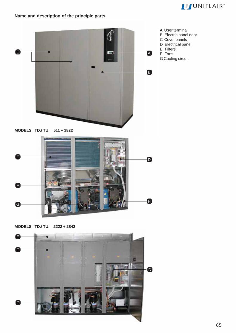
65
Name and description of the principle parts
A
B
C
A User terminalB Electric panel doorC Cover panelsD Electrical panelE FiltersF FansG Cooling circuit
DE
F
GH
E
D
F
G
MODELS TD./ TU. 511 ÷ 1822
MODELS TD./ TU. 2222 ÷ 2842

66
Description of the componentsA - User terminalAllows the unit to be turned on or off and the configurationand visualization of the condition of the machine.• A1 Display LCD• A2 ALARM key: visualization and re-set of alarms; when the alarm is activated it flashes red.• A3 PRG key: access to the configuration menu• A4 ESC key: exit from the screens• A5 UP key: scroll through the menu• A6 ENTER key: confirm• A7 DOWN key: scroll through the menu
B - Electrical panel doorAllows access to the electrical panel of the machine.C - Cover panelsAllow access to the internal components of the machineD - Electrical panel• D1 Magnetothermic
- auxiliary- heater (optional)- humidifier (optional)- fans- compressors
• D2 Interface board• D3 Dirty filter sensor• D4 Air flow sensor• D5 Main switch• D6 Terminal board• D7A Input/output electrical supply cables• D7B Input/output electrical auxiliary cables• D7C Input/output signal cables (RS485 and/or LAN)• D8 Phase sequence relay• D9 Maximum pressure manostat (only for mod. TD.
2222 ÷ 2842)
A2
A3
A4
A5
A6
A7
A1
FE
F1
D5
D1
D2
D3
D6
D7A
D4
D8
D7B
D7C
MODELS TD./ TU. 2222 ÷ 2842
MODELS TD./ TU. 511 ÷ 1822
E - FiltersFilter the air released into the room,
F - FansAllow the diffusion of air into the room.• F1 ATR transformer: allows the setting of the fan rotationspeed
D2 D1
D7A D7C D7BD7D
D3D4 D9
D5 D6D8

67
H1
H2
H
H3
G - Cooling circuit• G1 Compressor• G2 High pressure switch• G3 Schrader valve
G10
G3 G1G2
G4 G6
G7
G8
G5
G9
• G4 Safety valve• G5 Liquid receiver• G6 Dehydrating filter• G7 Flow sight glass• G8 Electronic thermostatic valve• G9 Brazed plate exchanger
• G10 Evaporating coil
H - Chilled water valve• H1 Servomotor• H2 Manual control knob• H3 Valve stem

68
I I - Room temperature and humidity sensor
Installation and maintenance of the Energy Saving units should be carried out as described in the DIRECTEXPANSION section. For the water circuit, follow the instructions in the CHILLED WATER section.
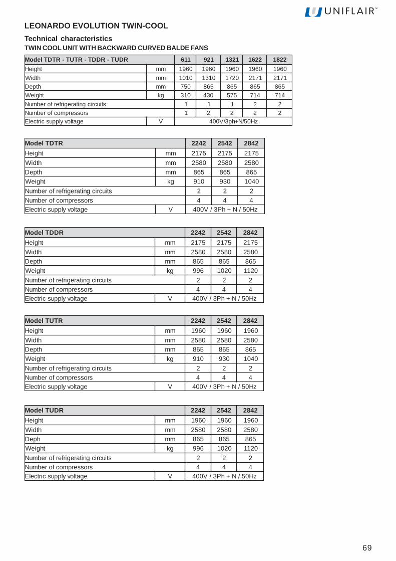
69
LEONARDO EVOLUTION TWIN-COOLTechnical characteristicsTWIN COOL UNIT WITH BACKWARD CURVED BALDE FANS
RDUT-RDDT-RTUT-RTDTledoM 116 129 1231 2261 2281thgieH mm 0691 0691 0691 0691 0691
htdiW mm 0101 0131 0271 1712 1712htpeD mm 057 568 568 568 568
thgieW gk 013 034 575 417 417stiucricgnitaregirferforebmuN 1 1 1 2 2
srosserpmocforebmuN 1 2 2 2 2egatlovylppuscirtcelE V zH05/N+hp3/V004
RTDTledoM 2422 2452 2482thgieH mm 5712 5712 5712
htdiW mm 0852 0852 0852htpeD mm 568 568 568
thgieW gk 019 039 0401stiucricgnitaregirferforebmuN 2 2 2
srosserpmocforebmuN 4 4 4egatlovylppuscirtcelE V zH05/N+hP3/V004
RDDTledoM 2422 2452 2482thgieH mm 5712 5712 5712
htdiW mm 0852 0852 0852htpeD mm 568 568 568
thgieW gk 699 0201 0211stiucricgnitaregirferforebmuN 2 2 2
srosserpmocforebmuN 4 4 4egatlovylppuscirtcelE V zH05/N+hP3/V004
RTUTledoM 2422 2452 2482thgieH mm 0691 0691 0691
htdiW mm 0852 0852 0852htpeD mm 568 568 568
thgieW gk 019 039 0401stiucricgnitaregirferforebmuN 2 2 2
srosserpmocforebmuN 4 4 4egatlovylppuscirtcelE V zH05/N+hP3/V004
RDUTledoM 2422 2452 2482thgieH mm 0691 0691 0691
htdiW mm 0852 0852 0852hpeD mm 568 568 568
thgieW gk 699 0201 0211stiucricgnitaregirferforebmuN 2 2 2
srosserpmocforebmuN 4 4 4egatlovylppuscirtcelE V zH05/N+hP3/V004
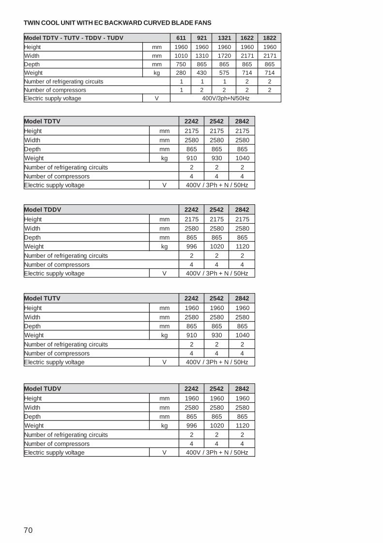
70
TWIN COOL UNIT WITH EC BACKWARD CURVED BLADE FANS
VDUT-VDDT-VTUT-VTDTledoM 116 129 1231 2261 2281thgieH mm 0691 0691 0691 0691 0691
htdiW mm 0101 0131 0271 1712 1712htpeD mm 057 568 568 568 568
thgieW gk 082 034 575 417 417stiucricgnitaregirferforebmuN 1 1 1 2 2
srosserpmocforebmuN 1 2 2 2 2egatlovylppuscirtcelE V zH05/N+hp3/V004
VTDTledoM 2422 2452 2482thgieH mm 5712 5712 5712
htdiW mm 0852 0852 0852htpeD mm 568 568 568
thgieW gk 019 039 0401stiucricgnitaregirferforebmuN 2 2 2
srosserpmocforebmuN 4 4 4egatlovylppuscirtcelE V zH05/N+hP3/V004
VDDTledoM 2422 2452 2482thgieH mm 5712 5712 5712
htdiW mm 0852 0852 0852htpeD mm 568 568 568
thgieW gk 699 0201 0211stiucricgnitaregirferforebmuN 2 2 2
srosserpmocforebmuN 4 4 4egatlovylppuscirtcelE V zH05/N+hP3/V004
VTUTledoM 2422 2452 2482thgieH mm 0691 0691 0691
htdiW mm 0852 0852 0852htpeD mm 568 568 568
thgieW gk 019 039 0401stiucricgnitaregirferforebmuN 2 2 2
srosserpmocforebmuN 4 4 4egatlovylppuscirtcelE V zH05/N+hP3/V004
VDUTledoM 2422 2452 2482thgieH mm 0691 0691 0691
htdiW mm 0852 0852 0852htpeD mm 568 568 568
thgieW gk 699 0201 0211stiucricgnitaregirferforebmuN 2 2 2
srosserpmocforebmuN 4 4 4egatlovylppuscirtcelE V zH05/N+hP3/V004
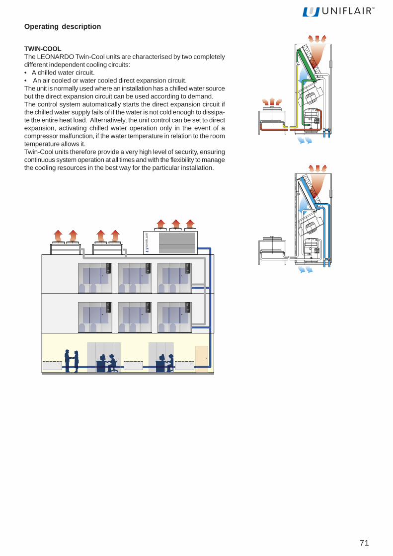
71
TWIN-COOLThe LEONARDO Twin-Cool units are characterised by two completelydifferent independent cooling circuits:• A chilled water circuit.• An air cooled or water cooled direct expansion circuit.The unit is normally used where an installation has a chilled water sourcebut the direct expansion circuit can be used according to demand.The control system automatically starts the direct expansion circuit ifthe chilled water supply fails of if the water is not cold enough to dissipa-te the entire heat load. Alternatively, the unit control can be set to directexpansion, activating chilled water operation only in the event of acompressor malfunction, if the water temperature in relation to the roomtemperature allows it.Twin-Cool units therefore provide a very high level of security, ensuringcontinuous system operation at all times and with the flexibility to managethe cooling resources in the best way for the particular installation.
Operating description
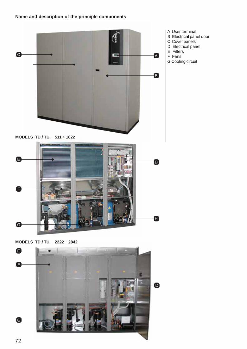
72
Name and description of the principle components
A
B
C
A User terminalB Electrical panel doorC Cover panelsD Electrical panelE FiltersF FansG Cooling circuit
DE
F
GH
E
D
F
G
MODELS TD./ TU. 511 ÷ 1822
MODELS TD./ TU. 2222 ÷ 2842

73
A2
A3
A4
A5
A6
A7
A1 Description of the componentsA - User terminalAllows the unit to be turned on or off and the configurationand visualization of the condition of the machine.• A1 LCD display• A2 ALARM key: visualization and re-set of alarms;
when the alarm is activated, it flashes red.• A3 PRG key: access to the configuration menu• A4 ESC key: exit from the screens• A5 UP key: scroll through the menu• A6 ENTER key: confirm• A7 DOWN key: scroll through the menu
B - Electrical panel doorAllows access to the electrical panel of the machine.
C - Cover panelsAllow access to the internal components of the machine.
D - Electrical panel• D1Magnetothermic
- auxiliary- heater (optional)- humidifier (optional)- fans- compressors
• D2Interface board• D3Dirty filter sensor• D4Air flow sensor• D5Main switch• D6Terminal board• D7AInput/output electrical supply cables• D7BInput/output electrical auxiliary cables• D7CInput/output condensing unit supply (optional) - (onlyon air cooled units)• D7DInput/output signal cables (RS485 and/or LAN)• D8Phase sequence relay• D9 Maximum pressure manostat (only for mod. TD.
2222 ÷ 2842)
E - FiltersFilter the air released into the room.
F - FansAllow the diffusion of air into the environment.• F1 ATR transformer allows the setting of the fan rotationspeed.
FE
F1
D5
D1
D2
D3
D6
D7A
D4
D8
D7BD7C
D7D
MODELS TD./ TU. 2222 ÷ 2842
D2 D1
D7A D7C D7BD7D
D3D4 D9
D5 D6D8
MODELS TD./ TU. 511 ÷ 1822

74
H - Chilled water valveH1 ServomotorH2 Manual control knobH3 Valve stem
H1
H2
H
H3
G - Cooling circuit• G1 Compressor• G2 High pressure switch• G3 Schrader valve
G10
G3 G1G2
G4 G6
G7
G8
G5
G9
• G4 Safety valve• G5 Liquid receiver• G6 Dehydration filter• G7 Flow sight glass• G8 Electronic thermostatic valve• G9 Brazed plate exchanger
• G10 Evaporating coil
75
I - Room temperature and humidity sensorI
Installation and maintenance of the Twin-cool units should be carried out as described in the DIRECT EXPANSIONsection. For the water circuit, follow the instructions in the CHILLED WATER section.
For the paragraph "Selecting the supply voltage of the fans", refer to the table below
STANDARD VOLTAGE LEVELS
MODELS WITH AUTOTRANSFORMERSIn the following table the maximum available pressures are indicated (expressed in Pa) for each voltage level of thetransformer. The values are given for the maximum air flow (expressed in m3/h).
sledoM V1150 0021160 002
1201-2290-1290-2270-12702201- 082
2231-1231-2211-1211 0722281-2261-2241 082
2422 0322452 0422482 062
RE*TRT*TRD*T
11501160
127022701290229012012201
1211221112312231
224122612281 2422 2452 2482
m[AF 3 ]=h/ 0555 0797 09311 02351 00012 00022 00722V aP aP aP aP aP aP aP
241 0 - - - - - -051 - - - - 0 0 0861 0 - - - - - -081 0 - - - 0 0 0591 0 - - - - - -002 - - - - 0 0 0512 85 - - - - - -222 68 - - - - - -722 601 - - - - - -032 321 0 0 0 0 0 0042 - - - - 73 0 0052 - 0 0 0 - - -062 - 0 0 0 29 05 12072 - 0 42 0 - - -082 - 3 35 5 041 89 86092 - 92 28 43 - - -003 - 55 211 36 681 041 011013 - 08 141 39 - - -023 - 601 171 221 622 081 841043 - 751 032 181 262 512 181063 - 802 882 042 392 642 212083 - 062 743 992 023 372 932004 113 604 853 343 592 162
Per variare le tensioni fare riferimento alle tabelle di pagina 33
76
MODELS WITH FANS CARRYING A CE MARKINGIn the following tables the maximum available pressures are indicated (expressed in Pa) for each supply voltage selected.The values are given for the maximum air flow (expressed in m3/h).
VE*TVT*TVD*T
11501160
127022701290229012012201
1211221112312231
224122612281 2422 2452 2482
m[AF 3 ]=h/ 0555 0497 05611 02451 00012 00022 00722% aP aP aP aP aP aP aP05 0 0 0 0 0 0 055 0 0 0 0 0 0 006 0 0 0 0 0 0 036 02 - - - - - -56 54 0 03 0 0 0 007 231 0 08 0 54 *53 057 0 54 651 72 531 58 5408 203 631 632 711 032 571 53158 0 922 023 802 713 562 03209 054 423 904 203 593 353 01359 0 124 105 993 015 554 514001 985 025 895 894 555 515 584
sledoM %1160-1150 362201-1270 272231-1211 462261-2241 37
2422 36 DT2452 27 DT2482 47 DT2422 07 UT2452 37 UT2482 57 UT
* Per modelli “TU” considerare -20 Pa
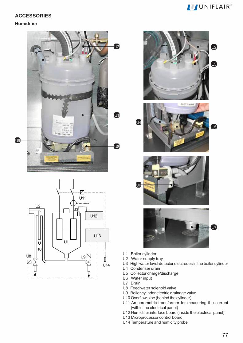
77
ACCESSORIESHumidifier
U2
U1
U8
U7
U1 Boiler cylinderU2 Water supply trayU3 High water level detector electrodes in the boiler cylinderU4 Condenser drainU5 Collector charge/dischargeU6 Water inputU7 DrainU8 Feed water solenoid valveU9 Boiler cylinder electric drainage valveU10 Overflow pipe (behind the cylinder)U11 Amperometric transformer for measuring the current
(within the electrical panel)U12 Humidifier interface board (inside the electrical panel)U13 Microprocessor control boardU14 Temperature and humidity probe
U9
U4U5
U3
U2
U6
U2
U10
U8
U14
U9
U1
U11
U3
U12
U13
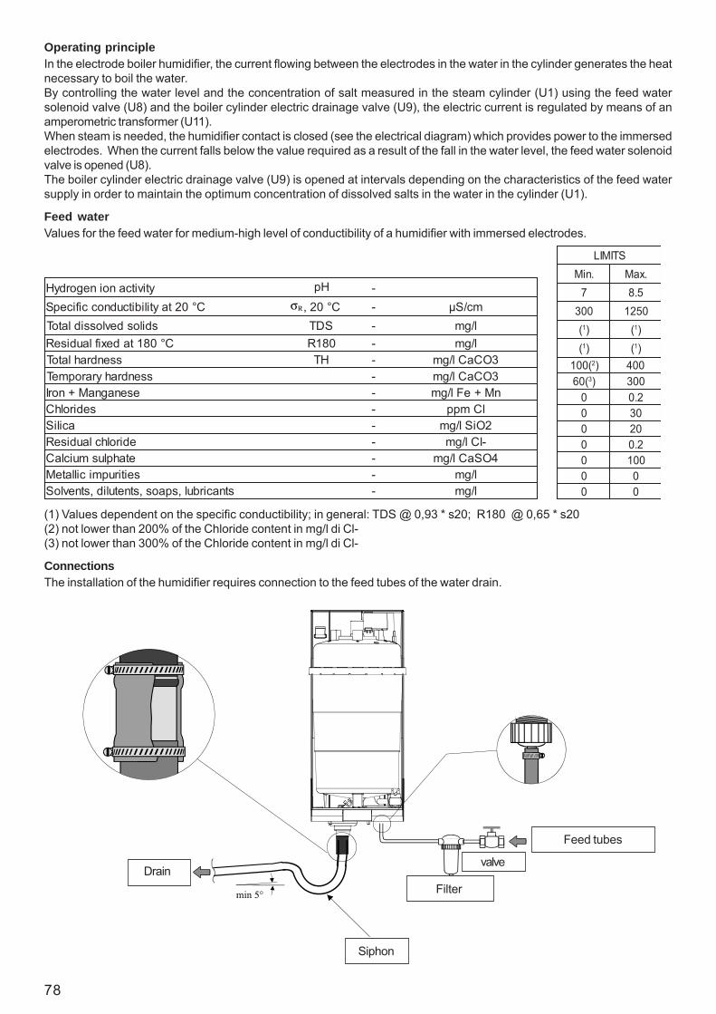
78
Operating principleIn the electrode boiler humidifier, the current flowing between the electrodes in the water in the cylinder generates the heatnecessary to boil the water.By controlling the water level and the concentration of salt measured in the steam cylinder (U1) using the feed watersolenoid valve (U8) and the boiler cylinder electric drainage valve (U9), the electric current is regulated by means of anamperometric transformer (U11).When steam is needed, the humidifier contact is closed (see the electrical diagram) which provides power to the immersedelectrodes. When the current falls below the value required as a result of the fall in the water level, the feed water solenoidvalve is opened (U8).The boiler cylinder electric drainage valve (U9) is opened at intervals depending on the characteristics of the feed watersupply in order to maintain the optimum concentration of dissolved salts in the water in the cylinder (U1).
Feed waterValues for the feed water for medium-high level of conductibility of a humidifier with immersed electrodes.
ConnectionsThe installation of the humidifier requires connection to the feed tubes of the water drain.
(1) Values dependent on the specific conductibility; in general: TDS @ 0,93 * s20; R180 @ 0,65 * s20(2) not lower than 200% of the Chloride content in mg/l di Cl-(3) not lower than 300% of the Chloride content in mg/l di Cl-
Feed tubes
Siphon
FilterDrain
valve
ytivitcanoinegordyH Hp -C°02taytilibitcudnoccificepS C°02, - mc/Sμ
sdilosdevlossidlatoT SDT - l/gmC°081tadexiflaudiseR 081R - l/gm
ssendrahlatoT HT - 3OCaCl/gmssendrahyraropmeT - 3OCaCl/gm
esenagnaM+norI - nM+eFl/gmsedirolhC - lCmpp
aciliS - 2OiSl/gmedirolhclaudiseR - -lCl/gmetahplusmuiclaC - 4OSaCl/gmseitirupmicillateM - l/gm
stnacirbul,spaos,stnetulid,stnevloS - l/gm
STIMIL.niM .xaM
7 5.8003 0521
(1) (1)(1) (1)
(001 2) 004(06 3) 003
0 2.00 030 020 2.00 0010 00 0
σR

79
MaintenanceThe only maintenance required is periodic inspection and cleaning of the steam boiler components. This should be carriedout at least once a year, preferably before the summer holiday shutdown.
BOILER CYLINDERLimescale deposits must be cleaned periodically from the electrodes and particles of limescale must be removed from thefilter at the base of the cylinder.To dismantle the cylinder:• - completely drain the water from the cylinder:
- using the user terminal, press the UP or DOWN key until the INPUT/OUTPUT screen appears;- confirm by using the ENTER key;- press the UP or DOWN key until DO6 HUMIDIFIER DRAIN is selected;- confirm by using the ENTER key;
• disconnect the power supply by opening the main isolator on the electrical panel;• disconnect the steam distributor hose from the top of the cylinder;• disconnect the power connections to the electrodes by unscrewing the terminal connectors and pull off the connectors
of the electrodes;• unclip the cylinder fixing strap;• pull the cylinder upwards.The boiler cylinder can be used many times after the electrodes are cleaned: however, it will eventually require replacementwhen the electrode meshes are too worn out to make further cleaning worthwhile.The spare part consists of only the cylinder itself (with the filter inside).
FEED AND DRAIN CONNECTIONSPeriodic inspections of the feed and drain connections are advisable in order to guarantee trouble-free operation of thehumidifier.Proceed as follows:• - completely drain the water from the cylinder:
- using the user terminal, press the UP or DOWN key until the INPUT/OUTPUT screen appears;- confirm by using the ENTER key;- press the UP or DOWN key until DO6 HUMIDIFIER DRAIN is selected;- confirm by using the ENTER key;
• disconnect the power supply by opening the main isolator on the electrical panel;• disconnect the feed line at the ¾ GAS connection to the inlet solenoid valve connection (U8);• extract, clean and replace the filter located inside the solenoid valve connection;• remove the drain solenoid valve, clean out the water pathways and remove any particles of limescale from the drain
siphon.

80
Electric heatersLeonardo Evolution units can be equipped with electric heaters. For each model there are two levels available: standardand improved.The finned elements are characterised by maintaining low power density of the surfaces in a highly efficient way, thereforelimiting overheating of the elements and consequently increasing their lifespan.Thanks to the low surface temperature of the heating elements, the ionisation effect on the air is limited. This heatingsystem has two functions:• heating the air to arrive at the set point conditions;• post-heating during the phase of dehumidification, in such a way as to retain the air temperature at set point.Therefore, the heating power installed is able to maintain the dry bulb temperature in the room during the dehumidificationprocess.
THERMOSTATTSR and TSRA
TSR and TSRA heaters safety thermostata are fixed on theexternal edges of the electrical panel.In position A for UPFLOW modelsIn position B for DOWNFLOW models
A
B
YTICAPACDRADNATS V oN Wk AO1160-1150 05/3/004 2 6 7,8
1290-2270-12702201-1201-2290 05/3/004 3 9 0,31
2231-1231-2211-12112281-2261-2241 05/3/004 5 51 7,12
2252-2222 05/3/004 6 81 62
2452-2422 05/3/004 6 81 62
2433-2482 05/3/004 8 42 7,43
YTICAPACDEVORPMI V oN Wk AO1160-1150 05/3/004 3 9 0,31
1290-2270-12702201-1201-2290 05/3/004 5 51 7,12
2231-1231-2211-12112281-2261-2241 05/3/004 6 81 0,62
2252-2222 05/3/004 8 42 7,43
2452-2422 05/3/004 8 42 7,43
2433-2482 05/3/004 9 72 93
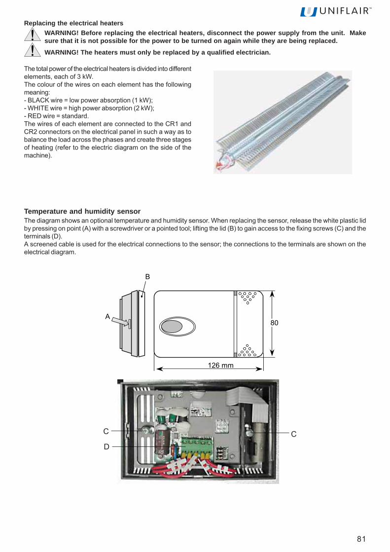
81
Replacing the electrical heatersWARNING! Before replacing the electrical heaters, disconnect the power supply from the unit. Makesure that it is not possible for the power to be turned on again while they are being replaced.
WARNING! The heaters must only be replaced by a qualified electrician.
The total power of the electrical heaters is divided into differentelements, each of 3 kW.The colour of the wires on each element has the followingmeaning:- BLACK wire = low power absorption (1 kW);- WHITE wire = high power absorption (2 kW);- RED wire = standard.The wires of each element are connected to the CR1 andCR2 connectors on the electrical panel in such a way as tobalance the load across the phases and create three stagesof heating (refer to the electric diagram on the side of themachine).
126 mm
80A
B
C CD
Temperature and humidity sensorThe diagram shows an optional temperature and humidity sensor. When replacing the sensor, release the white plastic lidby pressing on point (A) with a screwdriver or a pointed tool; lifting the lid (B) to gain access to the fixing screws (C) and theterminals (D).A screened cable is used for the electrical connections to the sensor; the connections to the terminals are shown on theelectrical diagram.

82
Connection to fresh air intakeThe unit can be fitted with an optional fresh air filter.During installation, connect the intake of the fresh air filter to the nearest external air inlet with a flexible hose which has adiameter of 100mm and secure the hose to the fresh air intake with a fastening collar.The connection from the unit to the external air inlet must have the shortest and straightest path possible.
Unit TD*C 0600 - 0700 Unit TU*C 0600 - 0700
Unit TD*C 1000 ÷ 2500 Unit TU*C 1000 ÷ 2500

83
MaintenanceClean, using a blast of compressed air, or replace the fresh air intake filters periodically.
STM
STM
2 m
Discharge temperature threshold sensor (only on CHILLED WATER models)An NTC temperature sensor is an optional accessory which maintains the supply air temperature of the unit above athreshold value. The sensor is connected to the microprocessor control system as described in the electrical diagram ofthe unit.The sensor has a temperature range of -50°C and +50°C and a protection level of IP67; it can be installed outside the unitby means of a cable which is 3 metres long. A minimum distance of 2 metres is advisable from the unit discharge, as shownin the diagram for upflow units.
Unit TDA-E-W 0511 - 0611 Unit TUA-E-W 0511 - 0611
UNIFLAIR S.p.A.Legal and administrative headquarters: Viale della Tecnica, 2 35026Conselve (PD) - ITALYTel. +39 049 5388211 Fax +39 0495388212uniflair.com - [email protected]. IVA 02160760282 C.C.I.A.A. di PD R.E.A. 212586 del 21/04/1988- R.I.N. 02160760282 M. PD004505
Fully paid-up share capital o 19.550.000 06MM115@00B0170