LEON-G100/G200 - ec-mobile.ruec-mobile.ru/user_files/File/u-blox/LEON-G100_G200_AT_Commands... ·...
262
LEON-G100/G200 Quad Band GSM/GPRS Data and Voice Modules AT Commands Manual Abstract Description of standard and proprietary AT Commands used with u-blox LEON-G100 and LEON-G200 Quad Band GSM/GPRS Data and Voice Modules. . locate, communicate, accelerate www.u-blox.com
Transcript of LEON-G100/G200 - ec-mobile.ruec-mobile.ru/user_files/File/u-blox/LEON-G100_G200_AT_Commands... ·...
LEON-G100/G200
Quad Band GSM/GPRS Data and Voice Modules
AT Commands Manual
Abstract
Description of standard and proprietary AT Commands used with u-blox LEON-G100 and LEON-G200 Quad Band GSM/GPRS Data
and Voice Modules.
.
loca
te,
com
mu
nic
ate
, acc
ele
rate
www.u-blox.com

LEON-G100/G200 - AT Commands Manual
GSM.G1-SW-09002-B Preface
Page 2 of 262
Document Information
Title LEON-G100/G200
Subtitle Quad Band GSM/GPRS Data and Voice Modules
Document type AT Commands Manual
Document number GSM.G1-SW-09002-B
Document status Preliminary
This document contains preliminary data, revised and supplementary data may be
published later.
This document applies to the following products:
Name Type number Firmware version PCN reference
LEON-G100 LEON-G100-00S-01 07.30 n.a.
LEON-G200 LEON-G200-00S-00 07.30 n.a.
This document and the use of any information contained therein, is subject to the acceptance of the u-blox terms and conditions. They can be downloaded from www.u-blox.com.
u-blox makes no warranties based on the accuracy or completeness of the contents of this document and reserves the right to make changes to specifications and product descriptions at any time without notice.
u-blox reserves all rights to this document and the information contained herein. Reproduction, use or disclosure to third parties without express permission is strictly prohibited. Copyright © 2009, u-blox AG.
u-blox® is a registered trademark of u-blox Holding AG in the EU and other countries.

LEON-G100/G200 - AT Commands Manual
GSM.G1-SW-09002-B Preliminary Preface
Page 3 of 262
Preface
u-blox Technical Documentation
As part of our commitment to customer support, u-blox maintains an extensive volume of technical
documentation for our products. In addition to our product-specific technical data sheets, the following manuals
are available to assist u-blox customers in product design and development.
AT Commands Manual: This document provides the description of the supported AT commands by the
LEON GSM/GPRS Voice and Data Modules to verify all implemented functionalities.
System Integration Manual: This Manual provides hardware design instructions and information on how to set up production and final product tests.
How to use this Manual
The LEON-G100/G200 AT Commands Manual provides the necessary information to successfully design in and configure these u-blox wireless modules. For navigating this document please note the following:
This manual has a modular structure. It is not necessary to read it from the beginning to the end.
The following symbols are used to highlight important information within the manual:
An index finger points out key information pertaining to module integration and performance.
A warning symbol indicates actions that could negatively impact or damage the module.
Questions
If you have any questions about u-blox Wireless Hardware Integration, please:
Read this manual carefully.
Contact our information service on our homepage http://www.u-blox.com
Read the questions and answers on our FAQ database
Technical Support
Worldwide Web
Our website (www.u-blox.com) is a rich pool of information. Product information, technical documents and helpful FAQ can be accessed 24h a day.
By E-mail
If you have technical problems or cannot find the required information in the provided documents, contact the nearest of the Technical Support offices by email. Use our service pool email addresses rather than any personal
email address of our staff. This makes sure that your request is processed as soon as possible. You will find the
contact details at the end of the document.
Helpful Information when Contacting Technical Support
When contacting Technical Support please have the following information ready:
Module type (e.g. LEON-G100-00S-01) and firmware version (e.g. 07.30)
Module configuration
Clear description of your question or the problem
A short description of the application
Your complete contact details

LEON-G100/G200 - AT Commands Manual
GSM.G1-SW-09002-B Preliminary Contents
Page 4 of 262
Contents
Preface ................................................................................................................................ 3
Contents .............................................................................................................................. 4
1 AT command mode at startup ................................................................................... 14
1.1 Power saving and CTS handshake ....................................................................................................... 15
1.2 DSR and RI activity .............................................................................................................................. 16
2 AT command features ................................................................................................ 17
2.1 Module connection settings ................................................................................................................ 17
2.2 Definitions .......................................................................................................................................... 17
2.3 Profiles ............................................................................................................................................... 18
2.4 Default values ..................................................................................................................................... 18
3 General operation ...................................................................................................... 19
3.1 Start up and initialization .................................................................................................................... 19
3.2 AT Commands mode .......................................................................................................................... 19
4 IPC – Inter Processor Communication ........................................................................ 20
4.1 Multiplexing mode +CMUX ................................................................................................................ 20
5 General commands ..................................................................................................... 22
5.1 Manufacturer identification +CGMI .................................................................................................... 22
5.2 Request model identification +CGMM ................................................................................................ 22
5.3 Request Firmware version +CGMR ...................................................................................................... 23
5.4 Request for IMEI +CGSN ..................................................................................................................... 23
5.5 Set TE character set +CSCS ................................................................................................................. 24
5.6 Request international mobile subscriber identification +CIMI .............................................................. 24
5.7 Card identification +CCID ................................................................................................................... 25
5.8 Request complete capabilities list +GCAP ........................................................................................... 25
5.9 Repeat last command A/ ..................................................................................................................... 26
6 Mobile equipment control and status commands ................................................... 27
6.1 Phone activity status +CPAS ............................................................................................................... 27
6.2 Switch off MT +CPWROFF .................................................................................................................. 27
6.3 Set phone functionality +CFUN ........................................................................................................... 28

LEON-G100/G200 - AT Commands Manual
GSM.G1-SW-09002-B Preliminary Contents
Page 5 of 262
6.4 Battery charge +CBC .......................................................................................................................... 29
6.5 Indicator control +CIND ...................................................................................................................... 30
6.6 Mobile termination event reporting +CMER........................................................................................ 31
6.7 Clock +CCLK ...................................................................................................................................... 32
6.8 Alarm +CALA ..................................................................................................................................... 32
6.9 Delete alarm +CALD ........................................................................................................................... 34
6.10 Restricted SIM access +CRSM .......................................................................................................... 34
6.11 Alert sound mode +CALM .............................................................................................................. 36
6.12 Ringer sound level +CRSL ................................................................................................................ 36
6.13 Loudspeaker volume level +CLVL .................................................................................................... 37
6.14 Mute control +CMUT ...................................................................................................................... 37
6.15 Call meter maximum event +CCWE ................................................................................................ 38
6.16 Set greeting text +CSGT ................................................................................................................. 38
6.17 Automatic Time Zone Update +CTZU .............................................................................................. 39
6.18 Time Zone Reporting +CTZR ........................................................................................................... 39
6.19 Report mobile termination error +CMEE ......................................................................................... 40
6.20 List all available AT commands +CLAC ............................................................................................ 41
7 Call control commands ............................................................................................... 42
7.1 Select type of address +CSTA ............................................................................................................. 42
7.2 Dial command D ................................................................................................................................. 42
7.3 Direct calling from phonebooks D> .................................................................................................... 44
7.4 Select tone dialling T........................................................................................................................... 45
7.5 Select pulse dialling P.......................................................................................................................... 45
7.6 Call answer A ..................................................................................................................................... 46
7.7 Hook control H ................................................................................................................................... 46
7.8 Monitor speaker loudness L ................................................................................................................ 46
7.9 Monitor speaker mode M ................................................................................................................... 47
7.10 Call mode +CMOD ......................................................................................................................... 47
7.11 Hang up call +CHUP ....................................................................................................................... 47
7.12 Extended error report +CEER .......................................................................................................... 48
7.13 Single numbering scheme +CSNS ................................................................................................... 48
7.14 Tone duration +VTD ....................................................................................................................... 49
7.15 DTMF and tone generation +VTS .................................................................................................... 49
7.16 Redial last telephone number DL ..................................................................................................... 50
7.17 Automatic answer S0 ...................................................................................................................... 50
8 Network service commands ...................................................................................... 52

LEON-G100/G200 - AT Commands Manual
GSM.G1-SW-09002-B Preliminary Contents
Page 6 of 262
8.1 Subscriber number +CNUM ................................................................................................................ 52
8.2 Signal quality +CSQ ............................................................................................................................ 52
8.3 Operator selection +COPS .................................................................................................................. 53
8.4 Network registration +CREG ............................................................................................................... 55
8.5 Preferred operator list +CPOL ............................................................................................................. 55
8.6 Read operator names +COPN ............................................................................................................. 56
8.7 User to user signalling service 1 +CUUS1 ............................................................................................ 57
9 Security commands .................................................................................................... 58
9.1 Enter PIN +CPIN .................................................................................................................................. 58
9.2 Facility lock +CLCK ............................................................................................................................. 59
9.3 Change password +CPWD ................................................................................................................. 61
10 Phonebook commands ............................................................................................... 63
10.1 Select phonebook memory storage +CPBS ...................................................................................... 63
10.2 Read phonebook entries +CPBR ...................................................................................................... 64
10.3 Find phonebook entries +CPBF ....................................................................................................... 65
10.4 Write phonebook entry +CPBW ...................................................................................................... 65
11 Short messages commands ....................................................................................... 67
11.1 Select message service +CSMS ........................................................................................................ 67
11.2 Preferred message storage +CPMS .................................................................................................. 68
11.3 Preferred message format +CMGF .................................................................................................. 69
11.4 Save settings +CSAS ....................................................................................................................... 69
11.5 Restore Settings +CRES ................................................................................................................... 70
11.6 Show text mode parameters +CSDH ............................................................................................... 70
11.7 New message indication +CNMI ..................................................................................................... 71
11.8 Read message +CMGR ................................................................................................................... 73
11.9 New Message Acknowledgement to MT +CNMA ........................................................................... 75
11.10 List message +CMGL....................................................................................................................... 76
11.11 Send message +CMGS .................................................................................................................... 79
11.12 Write message to memory +CMGW ............................................................................................... 79
11.13 Send message from storage +CMSS ................................................................................................ 80
11.14 Set text mode parameters +CSMP ................................................................................................... 81
11.15 Delete SMS +CMGD ....................................................................................................................... 82
11.16 Service center address +CSCA ......................................................................................................... 82
11.17 Select cell broadcast message types +CSCB .................................................................................... 83
LEON-G100/G200 - AT Commands Manual
GSM.G1-SW-09002-B Preliminary Contents
Page 7 of 262
12 Supplementary services commands .......................................................................... 84
12.1 Call forwarding +CCFC ................................................................................................................... 84
12.2 Call waiting +CCWA ....................................................................................................................... 85
12.3 Calling line identification restriction +CLIR ...................................................................................... 86
12.4 Calling line identification presentation +CLIP .................................................................................. 87
12.5 Connected line identification presentation +COLP .......................................................................... 88
12.6 Connected line identification restriction +COLR .............................................................................. 89
12.7 Advise of charge +CAOC ................................................................................................................ 89
12.8 Accumulated call meter +CACM ..................................................................................................... 90
12.9 Accumulated call meter maximum +CAMM .................................................................................... 91
12.10 Price per unit and currency table +CPUC ......................................................................................... 91
12.11 Call related supplementary services +CHLD ..................................................................................... 92
12.12 Call deflection +CTFR ...................................................................................................................... 92
12.13 List current calls +CLCC .................................................................................................................. 93
12.14 Supplementary service notifications +CSSN ..................................................................................... 94
12.15 Unstructured supplementary service data +CUSD ............................................................................ 95
12.16 Closed user group +CCUG .............................................................................................................. 96
12.17 Calling name presentation +CNAP .................................................................................................. 97
13 Data commands .......................................................................................................... 98
13.1 Select bearer service type +CBST ..................................................................................................... 98
13.2 Service class selection and identification +FCLASS ........................................................................... 98
13.3 Service reporting control +CR ......................................................................................................... 99
13.4 Cellular result codes +CRC ............................................................................................................ 100
13.5 Radio link protocol +CRLP ............................................................................................................. 100
14 FAX class 2 commands ............................................................................................. 102
14.1 Introduction .................................................................................................................................. 102
14.2 Adaptive answer +FAA ................................................................................................................. 102
14.3 Address & polling capabilities +FAP ............................................................................................... 103
14.4 Buffer size +FBS ............................................................................................................................ 103
14.5 Data bit order +FBO ...................................................................................................................... 104
14.6 HDLC frame reporting +FBU ......................................................................................................... 104
14.7 DS capabilities parameters +FCC ................................................................................................... 105
14.8 Copy quality checking +FCQ ......................................................................................................... 106
14.9 Capability to receive data +FCR ..................................................................................................... 106
14.10 Current session results +FCS ......................................................................................................... 107
LEON-G100/G200 - AT Commands Manual
GSM.G1-SW-09002-B Preliminary Contents
Page 8 of 262
14.11 DTE phase C response timeout +FCT............................................................................................. 107
14.12 Receive data +FDR ........................................................................................................................ 108
14.13 Transmit Data +FDT ...................................................................................................................... 108
14.14 Phase C received EOL alignment +FEA .......................................................................................... 108
14.15 Format conversion +FFC ................................................................................................................ 109
14.16 Report file transfer diagnostic frame +FFD..................................................................................... 109
14.17 Call termination status +FHS ......................................................................................................... 110
14.18 Procedure interrupt enable +FIE .................................................................................................... 110
14.19 Initialize facsimile parameters +FIP ................................................................................................ 111
14.20 Current session parameters +FIS ................................................................................................... 112
14.21 Inactivity timeout +FIT ................................................................................................................... 112
14.22 Session termination +FKS, +FK ...................................................................................................... 113
14.23 Local ID string +FLI ........................................................................................................................ 113
14.24 Set flow control +FLO ................................................................................................................... 114
14.25 Indicate document to poll +FLP ..................................................................................................... 114
14.26 Request manufacturer Identification +FMI ..................................................................................... 115
14.27 Request model identification +FMM .............................................................................................. 115
14.28 Request revision identification +FMR ............................................................................................. 115
14.29 Minimum phase C speed +FMS ..................................................................................................... 116
14.30 Negotiation reporting +FNR .......................................................................................................... 116
14.31 Non-standard frame FIF octet string +FNS ..................................................................................... 117
14.32 NSF message data indication +FND ............................................................................................... 117
14.33 Selective polling address +FPA ...................................................................................................... 118
14.34 Local polling ID string +FLI ............................................................................................................ 118
14.35 Packet protocol control +FPP ......................................................................................................... 119
14.36 Page status +FPS ........................................................................................................................... 119
14.37 Password parameter +FPW ........................................................................................................... 120
14.38 Receive quality thresholds +FRQ .................................................................................................... 120
14.39 Error correction mode retry count +FRY ........................................................................................ 121
14.40 SubAddress parameter +FSA ......................................................................................................... 121
14.41 Request to poll +FSP ..................................................................................................................... 121
14.42 Fax intermediate result codes ........................................................................................................ 122
15 V24 control and V25ter commands ......................................................................... 123
15.1 Reset to default configuration Z .................................................................................................... 123
15.2 Set to factory defined configuration &F ......................................................................................... 123
15.3 Circuit 109 behavior &C ................................................................................................................ 123

LEON-G100/G200 - AT Commands Manual
GSM.G1-SW-09002-B Preliminary Contents
Page 9 of 262
15.4 Circuit 108/2 behaviour &D ........................................................................................................... 124
15.5 DSR override &S ............................................................................................................................ 125
15.6 Flow control &K ............................................................................................................................ 125
15.7 Store current configuration &W .................................................................................................... 126
15.8 Display current configuration &V................................................................................................... 126
15.9 Designate a default reset profile &Y .............................................................................................. 127
15.10 Request identification information I............................................................................................... 128
15.11 Request manufacturer Identification +GMI .................................................................................... 128
15.12 Request model identification +GMM............................................................................................. 128
15.13 Request revision identification +GMR ............................................................................................ 129
15.14 Request product serial number identification +GSN ...................................................................... 129
15.15 DTE-DCE character framing +ICF ................................................................................................... 129
15.16 DTE-DCE local flow control +IFC ................................................................................................... 130
15.17 Set flow control \Q ........................................................................................................................ 131
15.18 Fixed DTE rate +IPR ....................................................................................................................... 131
15.19 System can Return to on-line data state O .................................................................................... 133
15.20 Escape character S2 ...................................................................................................................... 133
15.21 Command line termination character S3 ....................................................................................... 133
15.22 Response formatting character S4 ................................................................................................. 134
15.23 Command line editing character S5 .............................................................................................. 134
15.24 Pause before blind dialling S6 ....................................................................................................... 135
15.25 Connection completion timeout S7 ............................................................................................... 135
15.26 Command dial modifier time S8 .................................................................................................... 136
15.27 Automatic disconnect delay S10 ................................................................................................... 136
15.28 Escape prompt delay (EPD) S12 ..................................................................................................... 136
15.29 Command echo E ......................................................................................................................... 137
15.30 Result code suppression Q ............................................................................................................ 137
15.31 DCE response format V ................................................................................................................. 137
15.32 Result code selection and call progress monitoring control X ........................................................ 138
16 SIM toolkit ................................................................................................................ 138
16.1 Introduction .................................................................................................................................. 138
16.2 SIM-APPL-TK proactive commands +STKPRO ................................................................................ 139
16.3 SIM-APPL-TK terminal response +STKTR ........................................................................................ 141
16.4 SIM-APPL-TK envelope +STKENV ................................................................................................... 143
16.5 SIM-APPL-TK terminal profile +STKPROF ....................................................................................... 144
16.6 SIM-APPL-TK call control commands +STKCC ............................................................................... 144

LEON-G100/G200 - AT Commands Manual
GSM.G1-SW-09002-B Preliminary Contents
Page 10 of 262
16.7 SIM-APPL-TK proactive session status +STKCNF ............................................................................ 145
17 GPRS commands ....................................................................................................... 146
17.1 Parameters definition .................................................................................................................... 146
17.2 Define PDP context +CGDCONT ................................................................................................... 148
17.3 Quality of service profile (requested) +CGQREQ ............................................................................ 149
17.4 Quality of service profile (minimum acceptable) +CGQMIN ........................................................... 149
17.5 GPRS attach or detach +CGATT .................................................................................................... 150
17.6 PDP context activate or deactivate +CGACT .................................................................................. 150
17.7 Enter data state +CGDATA ........................................................................................................... 153
17.8 Enter IP state/GPRS IP dial D .......................................................................................................... 155
17.9 Show PDP address +CGPADDR ..................................................................................................... 155
17.10 GPRS mobile station class +CGCLASS ........................................................................................... 155
17.11 GPRS event reporting +CGEREP .................................................................................................... 156
17.12 GPRS network registration status +CGREG ................................................................................... 157
17.13 Select service for MO SMS messages +CGSMS .............................................................................. 158
17.14 Manaul deactivation of a PDP context H ....................................................................................... 159
17.15 Multiple PDP contexts ................................................................................................................... 159
18 Specific AT-commands ............................................................................................. 160
18.1 Firmware Update +UFWUPD ......................................................................................................... 160
18.2 Antenna Detection +UANTR ......................................................................................................... 161
18.3 ADC read command +UADC ........................................................................................................ 161
18.4 Power saving control (Power SaVing) +UPSV ................................................................................. 162
18.5 GPIO select configuration command +UGPIOC ............................................................................. 163
18.6 GPIO read command +UGPIOR ..................................................................................................... 164
18.7 GPIO set command +UGPIOW ...................................................................................................... 164
18.8 Tone generator (Tone GeNerator) +UTGN ..................................................................................... 165
18.9 Ringing tone selection command +URNG ..................................................................................... 165
18.10 SMS Alert sound mode (Message Sound Muting) +UMSM ............................................................ 166
18.11 I2S Digital Interface Mode +UI2S ................................................................................................... 167
18.12 Audio Path mode setting (Set Path Mode) +USPM ........................................................................ 172
18.13 Play audio resource (Play Audio Resource) +UPAR ......................................................................... 173
18.14 Stop audio resource (Stop Audio Resource) +USAR ....................................................................... 175
18.15 Play AMR audio file +UPLAYFILE ................................................................................................... 175
18.16 Stop AMR audio file +USTOPFILE .................................................................................................. 176
18.17 Network Congestion Detection +UCD........................................................................................... 176
18.18 Select GSM Band +UBANDSEL ...................................................................................................... 177

LEON-G100/G200 - AT Commands Manual
GSM.G1-SW-09002-B Preliminary Contents
Page 11 of 262
18.19 Set reporting call status +UCALLSTAT ........................................................................................... 178
18.20 GPRS Operator selection +UCGOPS .............................................................................................. 179
18.21 GPRS cell environment description +CGED .................................................................................... 180
18.22 Read counters of sent or received GPRS data +UGCNTRD ............................................................. 183
18.23 Set/reset counter of sent or received GPRS data +UGCNTSET ........................................................ 184
18.24 Read remaining SIM PIN attempts +UPINCNT ................................................................................ 185
18.25 Help displaying all commands &H ................................................................................................. 185
19 File System AT Commands ....................................................................................... 186
19.1 Download file +UDWNFILE ............................................................................................................ 186
19.2 Delete file +UDELFILE .................................................................................................................... 186
19.3 Read file +URDFILE ........................................................................................................................ 187
19.4 List files +ULSTFILE ........................................................................................................................ 187
20 Audio parameters tuning commands ..................................................................... 188
20.1 Introduction .................................................................................................................................. 188
20.2 Microphone Gain (Microphone Gain Control) +UMGC ................................................................. 188
20.3 Speaker Gain (Speaker Gain Control) +USGC ................................................................................ 189
20.4 Sidetone (SideToNe) +USTN .......................................................................................................... 190
20.5 Uplink Digital Filters (Uplink Biquad Filters) +UUBF ........................................................................ 191
20.6 Downlink Digital Filters (Downlink Biquad Filters) +UDBF ............................................................... 192
20.7 Hand Free Parameters (Hand Free Parameters) +UHFP ................................................................... 193
21 Data Connection Setup AT Commands ................................................................... 197
21.1 Packet Switched Data +UPSD ........................................................................................................ 197
21.2 Packet Switched Data Action +UPSDA .......................................................................................... 199
21.3 Packet Switched Network-assigned Data +UPSND ......................................................................... 200
21.4 Circuit Switched Data +UCSD ....................................................................................................... 200
21.5 Circuit Switched Data Action +UCSDA .......................................................................................... 201
21.6 Circuit Switched Network-assigned Data +UCSND ........................................................................ 202
22 DNS AT Commands .................................................................................................. 203
22.1 Resolve Name / IP Number through DNS +UDNSRN ...................................................................... 203
23 TCP/IP UDP/IP AT Commands ................................................................................. 204
23.1 Introduction .................................................................................................................................. 204
23.2 Create Socket +USOCR ................................................................................................................. 204
23.3 Set Socket Option +USOSO ........................................................................................................... 204
23.4 Get Socket Option +USOGO ......................................................................................................... 205
LEON-G100/G200 - AT Commands Manual
GSM.G1-SW-09002-B Preliminary Contents
Page 12 of 262
23.5 Close Socket +USOCL ................................................................................................................... 206
23.6 Get Socket Error +USOER .............................................................................................................. 206
23.7 Connect Socket +USOCO ............................................................................................................. 207
23.8 Write Socket Data +USOWR ......................................................................................................... 207
23.9 Read Socket Data +USORD ........................................................................................................... 208
23.10 Set Listening Socket +USOLI .......................................................................................................... 209
23.11 Firewall control +UFRW ................................................................................................................. 210
24 FTP AT Commands .................................................................................................... 212
24.1 File Transfer Protocol Control +UFTP ............................................................................................. 212
24.2 File Transfer Protocol Command +UFTPC ...................................................................................... 213
24.3 FTP Unsolicited Data Indication +UUFTPCD ................................................................................... 215
24.4 FTP Unsolicited Result Indication +UUFTPCR .................................................................................. 216
24.5 File Transfer Protocol Error +UFTPER .............................................................................................. 216
25 HTTP AT commands .................................................................................................. 217
25.1 HTTP Control +UHTTP ................................................................................................................... 217
25.2 HTTP Command +UHTTPC ............................................................................................................ 218
25.3 HTTP Command Result Unsolicited Indication +UUHTTPCR ........................................................... 220
25.4 HTTP rotocol Error +UHTTPER ....................................................................................................... 220
26 SMTP AT Commands ................................................................................................ 222
26.1 SMTP Control +USMTP ................................................................................................................. 222
26.2 SMTP Mail Control +USMTPM ...................................................................................................... 223
26.3 SMTP Command +USMTPC .......................................................................................................... 225
26.4 SMTP Command Result Unsolicited Indication +UUSMTPCR.......................................................... 225
26.5 SMTP Error +USMTPER .................................................................................................................. 226
27 GPS AT Commands ................................................................................................... 227
27.1 GPS Power Management +UGPS .................................................................................................. 227
27.2 GPS Profile configuration +UGPRF ................................................................................................. 228
27.3 AssistNow Online configuration +UGAOP ..................................................................................... 229
27.4 AssistNow Offline configuration +UGAOF ..................................................................................... 230
27.5 GPS Aiding request command +UGAOS ....................................................................................... 231
27.6 Send of UBX string +UGUBX ......................................................................................................... 231
27.7 GPS Indications timer +UGTMR ..................................................................................................... 232
27.8 Get GPS Time and date +UGZDA .................................................................................................. 232
27.9 Get GPS fix data +UGGGA ............................................................................................................ 233

LEON-G100/G200 - AT Commands Manual
GSM.G1-SW-09002-B Preliminary Contents
Page 13 of 262
27.10 Get geographic position +UGGLL .................................................................................................. 234
27.11 Get number of GNSS satellites in view +UGGSV ........................................................................... 234
27.12 Get recommended minimum GNSS data +UGRMC ....................................................................... 235
27.13 Get course over ground and ground speed +UGVTG .................................................................... 235
27.14 Get course over ground and ground speed +UGGSA .................................................................... 236
Appendix ........................................................................................................................ 237
A Appendix 1 ............................................................................................................... 237
A.1 Networking Error .............................................................................................................................. 237
A.2 Mobile Termination error result code +CME ERROR .......................................................................... 237
A.3 Message service failure result codes +CMS ERROR ............................................................................ 240
B AT Commands List .................................................................................................... 243
B.1 Parameters stored in profiles ............................................................................................................. 253
B.2 Parameters stored in non volatile memory ........................................................................................ 256
C Glossary .................................................................................................................... 257
Related documents......................................................................................................... 260
Revision history .............................................................................................................. 261
Contact ............................................................................................................................ 262

LEON-G100/G200 - AT Commands Manual
GSM.G1-SW-09002-B Preliminary AT command mode at startup
Page 14 of 262
1 AT command mode at startup By default, LEON-G100/G200 modules start with serial port 0 in AT command mode (configuration possible
using software with different functions at the serial port, this is out of the scope of this document).
Users can execute AT commands in accordance to this document and ETSI / 3GPP [2], [21] specifications.
LEON-G100/G200 modules are a Data Circuit-terminating Equipment (DCE) modem, in conformity to the
specifications in [21], [20], [26]. In this document the following serial line convention is used:
Serial lines at startup are:
Circuit 107, DSR: ON
Circuit 106, CTS: ON
Circuit 109, DCD: OFF
Circuit 126, RI: OFF
Circuit 108/2 DTR is relevant when the module is in data traffic only
Circuit 105 RTS is continuously monitored i.e. the flow control is usually hardware like default (AT&K3).
The CTS line and module power saving are synchronized to prevent the Data Terminal Equipment (DTE) from delivering data when the module cannot receive it. If power saving is enabled without hardware flow
control, the data provided by the DTE can be lost.
The modem UART connector lines operate within a voltage range of 0 V (space) to 1.8 V (mark). The EIA-
TIA RS-232 standard defines the ON state as +12 V and the OFF state as -12 V, which is too large a voltage range for telecom devices. Because of this the electrical values for the modem connector UART lines are
inverted and scaled with respect to the RS-232 electrical values. Note that the figures in this document use
the EIA-TIA RS-232 notation, while the real electrical values are inverted (ON=0 V, OFF=1.8 V).
DTE / Computer
DCE / Modem
Tx (103)
Rx (104)
RTS (105)
CTS (106)
DTR (108/2)
DSR (107)
DCD (109)
RI (126)

LEON-G100/G200 - AT Commands Manual
GSM.G1-SW-09002-B Preliminary AT command mode at startup
Page 15 of 262
1.1 Power saving and CTS handshake
The CTS line is used during power saving mode to prevent a remote DTE from sending data to the DCE when
the DCE cannot receive. During power saving mode, module activity and the system reference clock are reduced. Under these conditions the UART cannot receive data and the CTS line is switched to the OFF state. When the
module is connected to a network, it periodically wakes up in order to synchronize with network activity. Power
saving mode time is in relationship to network parameters and can be up to 450 GSM time frames (~2 s). Note that this time is not constant, it is only a maximum time reference and is valid when the module is connected to
the network. When the module wakes-up, the CTS line is switched ON and remains in this state for at least 3
GSM time frames (~14 ms). If the module is active on the network or data is delivered at the UART port, then the module remains in operation mode, otherwise it returns to power saving mode. The time amount until the
module enters power saving mode is variable and it depends on parameters such as:
Type of network activity
SW activity
Elapsed time since last data received at the serial port: after 5000 GSM frames (~23 s) without serial activity
(data transmitted or received) the serial drivers allow the module to enter power saving mode if there are no other activities
Figure 1 shows an example of CTS line activity inside and outside power saving mode in different scenarios. Most power saving mode scenarios have an unpredictable time line because they are influenced by external
events and network activity.
data input here
CTS ON
CTS OFF
time [# GSM frames]
max 450 GSM frames at least 5000 GSM frames
at least 3 GSM frames (without any activity)
Figure 1: CTS line activity

LEON-G100/G200 - AT Commands Manual
GSM.G1-SW-09002-B Preliminary AT command mode at startup
Page 16 of 262
1.2 DSR and RI activity
1.2.1 Incoming SMS
The RI line is also used to notify an SMS arrival. The RI switches from OFF to ON for 1 second as shown in Figure 2.
1s
RI ON
RI OFF 0 5 6
time
[s]
SMS arrives
Figure 2: RI line activity during SMS arrival
1.2.2 DSR at power on
After power on the DSR line follows the rule shown in Figure 3:
Tswitch
depends on the boot process duration (time from reset to UART initialization).
Figure 3: DSR line activity at power on
ON
DSR line
OFF
0 Tswitch
time [s]
power on

LEON-G100/G200 - AT Commands Manual
GSM.G1-SW-09002-B Preliminary AT command features
Page 17 of 262
2 AT command features
2.1 Module connection settings
For module and hyper terminal connection and settings see EVK-G25H Evalution Kit Getting Started [43].
2.2 Definitions
In this document the naming convention is to refer to the module as the DCE (Data Communications Equipment) or MT (Mobile Terminal) while the terminal that sends the command to the module is the TE (Terminal
Equipment) or DTE (Data Terminal Equipment). The terms DCE and DTE are used in the context of the serial
interface. A brief overview is shown below:
AT commands configure and enable the wireless module functionalities in accordance to 3GPP normative and
u-blox specifications. The AT commands are provided via a hyper terminal through a command line and are
described in the following chapters. A general description of each command is provided including functionalities, correct syntax to be provided by the TE/DTE, possible responses, and an example. The command description
defines each parameter of the command with its scope and parameter type, the supported values and the
default value (when available).
AT commands are typically provided to wireless modules using a command line with the following generic
syntax:
“AT”<command_name><string><CR><LF>
Where:
"AT" is a prefix to be set at the beginning of each command line
<command_name> is the command name string; it can have a “+” character as prefix
<string> is a string consisting of the value parameters following the syntax provided in this
manual;
<CR> is the carriage return character, with value specified by command S3.
<LF> is the linefeed character, with value specified by command S4.
The maximum number of command line characters for a single command is 512. This value depends on the
hyper terminal used; in some cases the number of characters is less.
When writing or sending an SMS, CtrlZ or ESC terminates the command; <CR> is used between the 2 parts
of the SMS (address and text).
If the command line could be performed successfully, the string “OK” is sent. In the following descriptions
<CR><LF> are intentionally omitted.
The command line is not case sensitive.
If a parameter is omitted, no value will be inserted between the two commas indicating the interested
parameter in the command line sent by the DTE.
The following rules are used when describing the command syntax:
<...>: Name in angle brackets is a parameter. The brackets themselves do not appear in the
command line;

LEON-G100/G200 - AT Commands Manual
GSM.G1-SW-09002-B Preliminary AT command features
Page 18 of 262
[...]: the square brackets represent the optional parameters of a command or an optional part of the TA information response. Brackets themselves do not appear in the command line. When
parameter is not given, the value will be set to the default.
The response format can be set with ATV command (for more details refer to the command description, section 15.31). The default setting (ATV1) is as follows:
Information responses: <CR><LF><text><CR><LF>
Result codes: <CR><LF><verbose code><CR><LF>
If the command is not accepted by the MT a message error will be displayed. The format of the message error
can be set with AT+CMEE command (see the command description form more details). The default setting
adopted in this manual is AT+CMEE=2 and the message error is displayed with this format:
+CME ERROR: <err>
where <err> represent the result code using verbose <err> values.
If the command is not supported or unknown, +CME ERROR: unknown is sent. If the command syntax is wrong, +CME ERROR: operation not supported is sent. If the parameters are wrong, +CME ERROR: <error> or +CMS
ERROR: <error> is sent. If no SIM-card is present or the PIN was not correctly entered, +CME ERROR: <error> is
sent for the most commands. <error> hints at the kind of the error. The list of all allowed errors is available in Appendix A.2 and A.3. For some commands only the message “ERROR” is displayed and is documented in the
command description.
2.3 Profiles
The default settings of some commands are stored in the memory of the wireless module (for a complete list of
the command please refer to chapter B). While a subset of these commands is stored in the non volatile memory, other default settings of the commands are organized in two personal profiles. The first profile is the
default profile and the data contained in him is used during the module power on (for the complete list of the
commands and their values please refer to B.1.
For more details related to the loading, storing and updating of the profiles please refer to AT&W (chapter 15.7),
AT&V (chapter 15.8) command description.
2.4 Default values
If the command parameters are optional, they can be also left out in the command line. In such cases normal
default values are assumed as follows:
In case of integer type parameters, the default value is 0, except the cases specified for each concerned command;
In case of text parameters, the default value is an empty string, except the cases specified for each
concerned command.

LEON-G100/G200 - AT Commands Manual
GSM.G1-SW-09002-B Preliminary General operation
Page 19 of 262
3 General operation
3.1 Start up and initialization
A complete start up can take place only with a SIM-card with disabled PIN-check. For a SIM-card with enabled
PIN check the most commands are answered with +CME ERROR: SIM-PIN requested. After entering PIN via
+CPIN command, which allows a start up completion, a lot of SIM-files will be read; it is possible that some commands are affected for a few seconds.
The serial interface driver does not allow a new command, until the old one is terminated by OK or +CME
ERROR: <error>.
If at start up the MT detects inconsistencies related to the NVRAM the following message is displayed: “! NVR
DOES NOT FIT TO SW-VERSION. NVR-update is needed !”.
3.2 AT Commands mode
3.2.1 Action Command
An action command is used to force the DCE to transmit an information or execute a specific action for the
command. A typical usage of this command mode is to provide the manufacturer settings proper of the DCE like manufacturer name, firmware version, etc.
3.2.2 Set Command
A Set Command is performed to set the preferred settings for the specific command. The set command is the only way to set the preferred settings in the DCE. For a subset of the commands is possible to store in the profile
the current settings and retrieve them in a another connection.
3.2.3 Read Command
A Read Command provides the current values of the command parameters. It is used to know the last
configuration of the parameters of the command.
3.2.4 Test Command
A Test Command provides the complete list of the values supported by each parameter of the command.
For a specific set of commands the information can be provided directly by the DCE when a specific event happens. This type of command is an unsolicited (or intermediate) result and can be enabled through a set
command.
3.2.5 Unsolicted Result Code (URC)
The unsolicted result code can have the same name of the command that enables it (e.g. +CREG) or can be
enabled by another command (e.g. unsolicited command: +CMTI, command that enables it: +CNMI)

LEON-G100/G200 - AT Commands Manual
GSM.G1-SW-09002-B Preliminary IPC – Inter Processor Communication
Page 20 of 262
4 IPC – Inter Processor Communication
4.1 Multiplexing mode +CMUX
4.1.1 Description
Enables the multiplexing protocol control channel as defined in 3GPP 27.010. The command sets parameters for
the Control Channel. If parameters are no specified, the default values are used. The response code is returned using the old interface speed. The parameters become active only after sending OK.
Usage of +CMUX command while multiplexing is not not allowed.
The Mux configuration is reported as follows:
Channel 0: Mux control
Channel 1: GPS reserved
Channel 2-5: available for free usage
Read commands are possible only on virtual channels (2-5)
Type Syntax Response Example
Set AT+CMUX=<mode>[,<subset>[,<port_speed>[,<N1>[,<T1>[,<N2>[,<T2>[,<T3>[,<k>]]]]]]]
OK
Read AT+CMUX? +CMUX: <mode>,[<subset>],<port_speed>,<N1>,<T1>,<N2>,<T2>,<T3>[,<k>]
OK
+CMUX: 0,0,0,0,0,0,0,0,0
OK
Test AT+CMUX=? +CMUX: (list of supported <mode>s),(list of supported <subset>s),(list of supported <port_speed>s), (list of supported <N1>s), (list of supported <T1>s),(list of supported <N2>s),(list of supported <T2>s),(list of supported <T3>s), (list of supported <k>s)
OK
+CMUX: (0),(0),(0),(1-1509),(1-255),(0-5),(2-255),(0),(0)
OK

LEON-G100/G200 - AT Commands Manual
GSM.G1-SW-09002-B Preliminary IPC – Inter Processor Communication
Page 21 of 262
4.1.2 Defined Values
M / O mandatory or optional parameters. Unless otherwise specified, all parameters are mandatory.
Parameter Type M / O Description
<mode>
Integer M Multiplexer Transparency Mechanism
0: Basic option (default);
1-7: currently not supported, in case of read command 0 is returned.
<subset>
Integer M Char set
0: UIH frames used only (Default value);
1: UI frames used only; value currently not supported;
2: I frames used only; value currently not supported.
<port_speed>
Integer M Transmission rate; this parameter is not supported and the value 0 is always displayed in case of read command.
<N1>
Integer Maximum frame size
1-1509: Currently only the range 1-1509 is supported;
<T1>
Integer Acknowledgement timer in units of ten milliseconds
1-255; currently only the value 253 is supported
<N2> Integer O Maximum number of re-transmissions
0-5: 3 is default; currently only the range 0-5 is supported
<T2>
Response timer for the multiplexer control channel in units of ten milliseconds
2-255; currently only the value 254 is supported
<T3>
Wake up response timer in seconds
only the value 0 is currently supported
<k>
Window size, for Advanced operation with Error Recovery options
only the value 0 is currently supported
T2 must be longer than T1.

LEON-G100/G200 - AT Commands Manual
GSM.G1-SW-09002-B Preliminary General commands
Page 22 of 262
5 General commands
5.1 Manufacturer identification +CGMI
5.1.1 Description
Text string, determined by the manufacturer, identifying the manufacturer.
Type Syntax Response Example
Action AT+CGMI <manufacturer>
OK
Test AT+CGMI=? OK
5.1.2 Defined Values
Parameter Type M / O Description
<manufacturer> String manufacturer name
5.2 Request model identification +CGMM
5.2.1 Description
Text string, determined by the manufacturer, identifying the manufacturer.
Type Syntax Response Example
Action AT+CGMM <model>
OK
Test AT+CGMM=? OK
5.2.2 Defined Values
Parameter Type M / O Description
<model> String Name of model
LEON-G100/G200 - AT Commands Manual
GSM.G1-SW-09002-B Preliminary General commands
Page 23 of 262
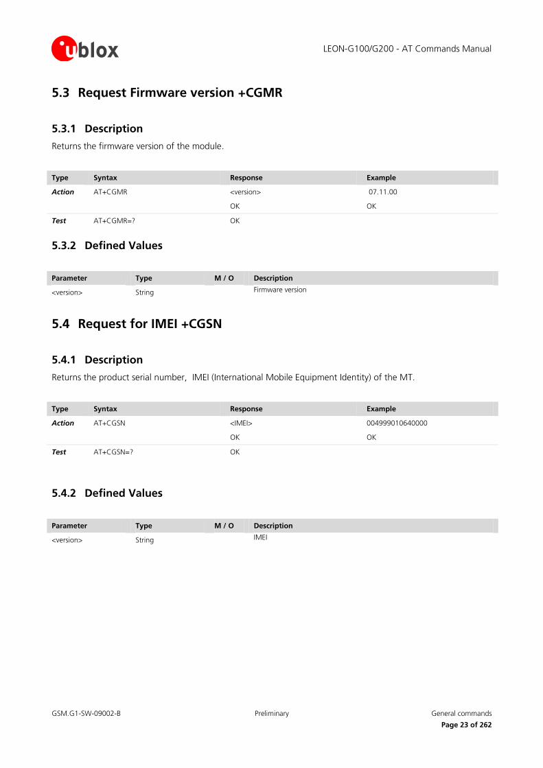
5.3 Request Firmware version +CGMR
5.3.1 Description
Returns the firmware version of the module.
Type Syntax Response Example
Action AT+CGMR <version>
OK
07.11.00
OK
Test AT+CGMR=? OK
5.3.2 Defined Values
Parameter Type M / O Description
<version> String Firmware version
5.4 Request for IMEI +CGSN
5.4.1 Description
Returns the product serial number, IMEI (International Mobile Equipment Identity) of the MT.
Type Syntax Response Example
Action AT+CGSN <IMEI>
OK
004999010640000
OK
Test AT+CGSN=? OK
5.4.2 Defined Values
Parameter Type M / O Description
<version> String IMEI

LEON-G100/G200 - AT Commands Manual
GSM.G1-SW-09002-B Preliminary General commands
Page 24 of 262
5.5 Set TE character set +CSCS
5.5.1 Description
Selects the TE character set.
Type Syntax Response Example
Set AT+CSCS=<chset> OK AT+CSCS=”IRA”
OK
Read AT+CSCS? +CSCS=<chset>
OK
+CSCS="IRA"
OK
Test AT+CSCS=? +CSCS: (list of supported <chset>'s)
OK
+CSCS: ("IRA","GSM","PCCP437","8859-1","UCS2","HEX")
OK
5.5.2 Defined Values
Parameter Type M / O Description
<chset>
String M “IRA”: International Reference Alphabet (ITU-T T.50)
“GSM”: GSM default alphabet (3GPP TS 23.038)
“PCCP437”: PC character set Code Page 437
“8859-1”: ISO 8859 Latin 1 character set
“UCS2”: 16-bit universal multiple-octet coded character set (USO/IEC10646); UCS2 character strings are converted to hexadecimal numbers from 0000 to FFFF. Only the strings found in quotation marks are UCS2 coded, the rest of commands or responses, remains in IRA alphabet
"HEX": character strings consist only of hexadecimal numbers from 00 to FF; e.g. "032FE6" equals three 8-bit characters with decimal values 3, 47 and 230; no conversions to the original MT character set shall be done
5.6 Request international mobile subscriber identification +CIMI
5.6.1 Description
Request the IMSI (International Mobile Subscriber Identity).
Type Syntax Response Example
Action AT+CIMI <IMSI>
OK
222107701772423
OK
Test AT+CIMI=? OK
LEON-G100/G200 - AT Commands Manual
GSM.G1-SW-09002-B Preliminary General commands
Page 25 of 262
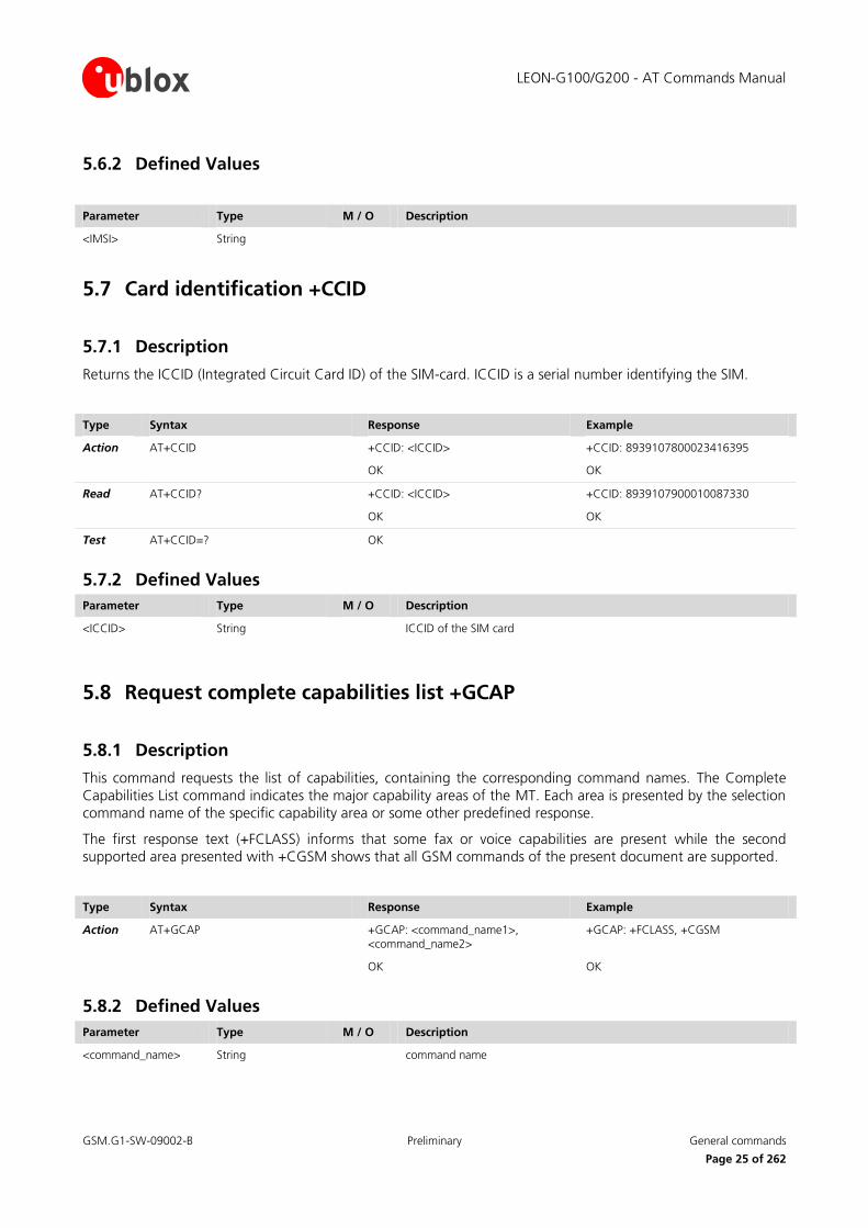
5.6.2 Defined Values
Parameter Type M / O Description
<IMSI> String
5.7 Card identification +CCID
5.7.1 Description
Returns the ICCID (Integrated Circuit Card ID) of the SIM-card. ICCID is a serial number identifying the SIM.
Type Syntax Response Example
Action AT+CCID +CCID: <ICCID>
OK
+CCID: 8939107800023416395
OK
Read AT+CCID? +CCID: <ICCID>
OK
+CCID: 8939107900010087330
OK
Test AT+CCID=? OK
5.7.2 Defined Values
Parameter Type M / O Description
<ICCID> String ICCID of the SIM card
5.8 Request complete capabilities list +GCAP
5.8.1 Description
This command requests the list of capabilities, containing the corresponding command names. The Complete
Capabilities List command indicates the major capability areas of the MT. Each area is presented by the selection
command name of the specific capability area or some other predefined response.
The first response text (+FCLASS) informs that some fax or voice capabilities are present while the second
supported area presented with +CGSM shows that all GSM commands of the present document are supported.
Type Syntax Response Example
Action AT+GCAP +GCAP: <command_name1>, <command_name2>
OK
+GCAP: +FCLASS, +CGSM
OK
5.8.2 Defined Values
Parameter Type M / O Description
<command_name> String command name

LEON-G100/G200 - AT Commands Manual
GSM.G1-SW-09002-B Preliminary General commands
Page 26 of 262
5.9 Repeat last command A/
5.9.1 Description
Repeats the previously executed command again. Only the A/ command can not be repeated.
Type Syntax Response Example
Action A/
If autobauding is active, the command A/ cannot be used.

LEON-G100/G200 - AT Commands Manual
GSM.G1-SW-09002-B Preliminary Mobile equipment control and status commands
Page 27 of 262
6 Mobile equipment control and status commands
6.1 Phone activity status +CPAS
6.1.1 Description
Returns the activity status <pas> of the MT.
Type Syntax Response Example
Action AT+CPAS +CPAS: <pas>
OK
Test AT+CPAS=? +CPAS: (list of supported <pas>s)
OK
+CPAS: (0-5)
OK
6.1.2 Defined Values
Parameter Type M / O Description
<pas> Integer M 0: ready (MT allows commands from DTE)
1: unavailable (MT does not allow commands from DTE)
2: unknown (MT is not guaranteed to respond to instructions)
3: ringing (MT is ready for commands from DTE, but the ringer is active)
4: call in progress (MT is ready for commands from DTE, but a call is in progress)
5: asleep (ME is unable to process commands from DTE because it is in a low functionality state)
6.2 Switch off MT +CPWROFF
6.2.1 Description
Switches off the MT. During shut-down current settings are saved in module’s non-volatile memory.
Using this command can result in following command line being ignored.
Type Syntax Response Example
Action AT+CPWROFF OK
Test AT+CPWROFF=? OK

LEON-G100/G200 - AT Commands Manual
GSM.G1-SW-09002-B Preliminary Mobile equipment control and status commands
Page 28 of 262
6.3 Set phone functionality +CFUN
6.3.1 Description
Selects level of functionality <fun> in the MT.
If the syntaxes +CFUN=0, +CFUN=15 or +CFUN=16 (resets) are used, the rest of the command line,
placed after that, will be ignored.
If the syntaxes +CFUN=0 or +CFUN=15 or +CFUN=16 (resets) are used, the rest of the command line, placed
after that, will be ignored.
Type Syntax Response Example
Set AT+CFUN=<fun> OK AT+CFUN=1
OK
Read AT+CFUN? +CFUN: <power_mode>,<STK_mode>
OK
+CFUN: 1,0
OK
Test AT+CFUN=? +CFUN: (list of supported <fun>’s)
OK
+CFUN: (0,1,6,7,8,15,16)
OK
6.3.2 Defined Values
Parameter Type M / O Description
<fun> Integer M Selected functionality
0: minimum functionality meaning switch off of the MT
1: full functionality meaning start up MT (from offline mode)
6: enables the SIM-toolkit interface and fetching of proactive commands by SIM-APPL from the SIM-card
7: disables the SIM-toolkit interface and enables fetching of proactive commands by SIM-APPL from the SIM-card
8: disable fetching of proactive commands by SIM-APPL from the SIM-card
15: silent reset (reset MT without resetting the SIM)
16: Reset (reset MT with resetting the SIM)
<power_mode> Integer M 1: MT is switched on
2: invalid mode
<STK_mode> Integer M 0: inactive state
6: enables the SIM-toolkit interface and fetching of proactive commands by SIM-APPL from the SIM-card
7: disables the SIM-toolkit interface and enables fetching of proactive commands by SIM-APPL from the SIM-card
8: disable fetching of proactive commands by SIM-APPL from the SIM-card

LEON-G100/G200 - AT Commands Manual
GSM.G1-SW-09002-B Preliminary Mobile equipment control and status commands
Page 29 of 262
6.4 Battery charge +CBC
6.4.1 Description
Returns battery status <bcs> and battery charge level <bcl> of the MT. The charge level <bcl> will be also used to build and display the indicator “battchg” i.e. battery charge level in the response code +CIND (refer to
chapter 6.5) and in the URC +CIEV (refer to chapter 6.6). The following mapping of “battchg” to <bcl> exists:
“battchg” <bcl>
0 < 17 %
1 < 33 %
2 < 50 %
3 < 67 %
4 < 83 %
5 >= 83 %
Type Syntax Response Example
Action AT+CBC +CBC: <bcs>,<bcl>
OK
+CBC: 0,69
OK
Test AT+CBC=? +CBC: (list of supported <bcs>’s), (list of supported <bcl>’s)
OK
+CBC: (0-3),(0-100)
OK
6.4.2 Defined Values
Parameter Type M / O Description
<bcs> Integer M Battery status
0: MT is powered by the battery
1: MT has a battery connected, but is not powered by it
2: MT does not have a battery connected
3: Recognized power fault, calls inhibited
<bcl> Integer M Battery charge level
0: battery is exhausted, or MT does not have a battery connected;
1..100: battery has 1-100 percent remaining.

LEON-G100/G200 - AT Commands Manual
GSM.G1-SW-09002-B Preliminary Mobile equipment control and status commands
Page 30 of 262
6.5 Indicator control +CIND
6.5.1 Description
Provides the status of the data module about the battery, the network status, SMS, GPRS, etc.
The test command returns pairs, where string value <descr> is a maximum 16 character description of the
indicator and compound value is the allowed value for the indicator.
Because all possible supported parameters of the set syntax can not be overwritten, the setting will be
ignored and the MT sends the corresponding final result code OK to DTE.
Type Syntax Response Example
Set AT+CIND=[<ind>[,<ind>[,...]]] OK OK
Read AT+ CIND? +CIND: <ind>[,<ind>[,...]]
OK
+CIND: 2,0,0,0,0,0,0,0,0,0,0
OK
Test AT+ CIND=? +CIND: (list of <descr>s)
OK
+CIND: ("battchg",(0-5)),("signal",(0-5)),("service",(0,1)),("sounder",(0,1)),("message",(0,1)),("call",(0,1)),("roam",(0,1)),("smsful",(0,1)),("gprs",(0-2)),("callsetup",(0-3)),("callheld",(0-1))
OK
6.5.2 Defined Values
Parameter Type M / O Description
<ind> Integer M Integer type value, which shall be in range of corresponding <descr>
<descr> String These values are reserved by the norm and their <ind> ranges; it may have the values:
“battchg”: battery charge level (0-5); see also +CBC (refer to chapter 6.4) for details
“signal”: signal quality (0-5); see also +CSQ (chapter 8.2) for details
“service”: service availability (0,1) o 0 means no service o 1 means service available
“sounder”: sounder activity (0,1) o 0 means no sound o 1 means sound available
“message”: message received (0,1) o 0 means no messages o 1 means message(s) received
“call”: call in progress (0,1) o 0 means no call active o 1 means a call is active
“roam”: roaming indicator (0,1); see +CREG (chapter 8.4) for details
“smsfull”: SMS full status (0-1); at receiving of SMS the used memory storage becomes full (1), or memory allocations are available (0)
“gprs”: GPRS registration status (0-2): o 0 means not registered and GPRS network not available; o 1 means GPRS available but not registered; o 2 means GPRS registered
“callsetup” : call setup status indicator destinated for devices usage (not covered by [2]) (0-3); possible values are:

LEON-G100/G200 - AT Commands Manual
GSM.G1-SW-09002-B Preliminary Mobile equipment control and status commands
Page 31 of 262
Parameter Type M / O Description
o 0: “not currently in call setup” o 1: “incoming call process ongoing” o 2: “outgoing call setup is ongoing” o 3: “remote party being alerted in an ongoing call”
“callheld” : call held indicator destinated for devices (not covered by [2]) (0-2); possible values are: o 0: “no calls held” o 1: “call on hold”
6.6 Mobile termination event reporting +CMER
6.6.1 Description
Enables or disables sending of URCs from MT to DTE in the case of key pressings, display changes and indicator
state changes. <mode> parameter controls the processing of URCs specified within this command.
Type Syntax Response Example
Set AT+CMER=[<mode>[,<keyp>[,<disp>[,<ind>[,<bfr>]]]]]
OK AT+CMER=1,0,0,2,1
OK
Read AT+CMER? +CMER: <mode>,<keyp>,<disp>,<ind>,<bfr>
OK
+CMER: 1,0,0,0,1
OK
Test AT+CMER=? +CMER: (list of supported <mode>’s), (list of supported <keyp>’s), (list of supported <disp>’s), (list of supported <ind>’s), ( list of supported <bfr>’s)
OK
+CMER: (0-3),(0),(0),(0-2),(0,1)
OK
URC +CIEV: <ind>,<value>
6.6.2 Defined Values
Parameter Type M / O Description
<mode> Integer M 0: buffer URCs in the MT
1: discard URCs when the V.24 interface is reserved for data; otherwise display them on DTE directly
2: buffer URCs in MT when the V.24 interface is reserved and flush them after reservation; otherwise display them on DTE directly
3: forward URCs directly to the DTE
<keyp> Integer M 0: no keypad event reporting
<disp> Integer M 0: no display event reporting
<ind> Integer M 0: no indicator event reporting
1: indicator event reporting using result code +CIEV: <ind>,<value>
where <ind> indicates the indicator order number (as specified for +CIND) and <value> is the new value indicator. Only the indicator events which are not caused by +CIND shall be indicated by the MT to the DTE.
2: indicator event reporting using result code +CIEV: <ind>,<value>. All indicator events shall be directed from MT to DTE.
<bfr> Integer M 0: MT buffer of URCs defined within this command is cleared when <mode> 1...3 is entered
1: MT buffer of URCs defined within this command is flushed to the DTE when <mode> 1...3 is entered (OK response shall be given before flushing the codes).

LEON-G100/G200 - AT Commands Manual
GSM.G1-SW-09002-B Preliminary Mobile equipment control and status commands
Page 32 of 262
6.7 Clock +CCLK
6.7.1 Description
Sets the real-time clock of the MT.
Type Syntax Response Example
Set AT+CCLK=<time> OK AT+CCLK=”02/07/01,14:54:00+01”
OK
Read AT+CCLK? +CCLK:<time>
OK
+CCLK: “02/07/01,14:55:00+01”
OK
Test AT+CCLK=? OK
6.7.2 Defined Values
Parameter Type M / O Description
<time> String Format is “yy/MM/dd,hh:mm:ss±TZ”. Characters indicate year, month, day, hour, minutes, seconds, time zone.
"TZ:" The Time Zone information is represented by two digits; the display of TZ for query contains
always this information but it is updated only if the automatic time zone update is enabled via AT+CTZU
command (before the registration on the network) and the network supports the time zone information.
6.8 Alarm +CALA
6.8.1 Description
Sets an alarm time in the MT. There can be an array of different types of alarms. If the setting fails, a +CME
ERROR: <error> is returned. To set up a recurrent alarm for more days in the week, the <recurr> parameter is
used. When an alarm is timed out, the alarm actions are executed:
Sound alarm (if not silent);
URC +CALV: <n> is displayed on DTE.
Type Syntax Response Example
Set AT+CALA=<time>[,<n>[,<type>[,<text>[,<recurr>[,<silent>]]]]]
OK AT+CALA=”02/07/01,14:56:00+04”,1,1,”Alarm”
OK
Read AT+CALA? [+CALA: <time>,<n1>,<type>,[<text>],[<recurr>],<silent>
[+CALA: <time>,<n2>,<type>,[<text>],[<recurr>],<silent>
[...]]]
OK
+CALA:
”02/07/01,14:56:00+04”,1,0,”Alarm”,0
OK

LEON-G100/G200 - AT Commands Manual
GSM.G1-SW-09002-B Preliminary Mobile equipment control and status commands
Page 33 of 262
Type Syntax Response Example
Test AT+CALA=? +CALA: (list of supported <n>s),(list of supported <type>s),<tlength>,<rlength>,(list of supported <silent>’s)
OK
+CALA: (1-3),,255,13,(0-1)
OK
URC +CALV: <n>
6.8.2 Defined Values
Parameter Type M / O Description
<time> String Format is “yy/MM/dd,hh:mm:ss±TZ”. Characters indicate year, month, day, hour, minutes, seconds, time zone.
<n>, <n1>, <n2> Integer M indicates the index of the alarm, the allowed ranges are 1-3; if not indicated by user, default value 1 is assumed
<type> Type of the alarm; this parameter is ignored.
<text> String Indicates the text to be displayed when alarm time is reached; this parameter is ignored
<tlength> Integer Indicates the maximum length of <text>; this parameter is ignored
<recurr> String Maximum string length is 13, indicates day of week for the alarm in one of the following formats:
<1..7>[,<1..7>[…]]: Sets a recurrent alarm for one or more days in the week. The digits 1 to 7 corresponds to the days in the week, Monday (1), …, Sunday (7). Example: The string "1,2,3,4,5" may be used to set an alarm for some weekdays.
“0”: Sets a recurrent alarm for all days in the week and all following weeks
<rlength> Integer M Indicates the maximum length of <recurr>
<silent> Integer M Indicates if the alarm is silent or not
1: the alarm will be silent and the only result from the alarm is the URC +CALV.
0: the alarm will not be silent.
6.8.3 Switching off module after setting the alarm
Alternatively the module can be switched off after setting the alarm, the module switches on as soon as the
alarm has expired. The following procedure can be followed:
Set the RTC clock by AT command: AT+CCLK=”06/12/29,11:00:00+00” (you can check the time set by AT+CCLK?);
Set the RTC alarm by AT command: AT+CALA=”06/12/29,11:01:00+00”,1,0,””,””,0 (you can check the alarm set by AT+CALA?);
Switch off the MT with AT+CPWROFF;
Output: The MT switches on as soon as the minute is expired and answers “+CALV:1”. Try to send “AT” on the hyper terminal, the MT replies properly.
If the MT cannot generate an alarm tone, only the text is displayed at alarm time

LEON-G100/G200 - AT Commands Manual
GSM.G1-SW-09002-B Preliminary Mobile equipment control and status commands
Page 34 of 262
6.9 Delete alarm +CALD
6.9.1 Description
Deletes an alarm in the MT.
Type Syntax Response Example
Set AT+CALD=<n> OK AT+CALD=0
OK
Test AT+CALD=? +CALD: (list of <n>s)
OK
+CALD: (1-3)
OK
6.9.2 Defined Values
Parameter Type M / O Description
<n> Integer M Indicates the index of the alarm; refer to +CALA description for the allowed range of indexes.
6.10 Restricted SIM access +CRSM
6.10.1 Description
Allows easy access to the SIM database. Set command transmits to the MT the SIM <command> and its required
parameters. MT handles internally all SIM-MT interface locking and file selection routines. As response to the
command, MT sends the actual SIM information parameters and response data. MT error result code +CME ERROR may be returned when the command cannot be passed to the SIM, but the failure in the execution of the
command in the SIM is reported in <sw1> and <sw2> parameters.
Type Syntax Response Example
Set AT+CRSM=<command>[,<fileid>[,<P1>,<P2>,<P3>[,<data> [,<pathid>]]]]
+CRSM: <sw1>,<sw2>[,<response>]
OK
AT+CRSM=176,28471,0,0,3
OK
Test AT+CRSM=? OK

LEON-G100/G200 - AT Commands Manual
GSM.G1-SW-09002-B Preliminary Mobile equipment control and status commands
Page 35 of 262
6.10.2 Defined Values
Parameter Type M / O Description
<command> Integer M 176: read binary
178: read record
192: get response
214: update binary
220: update record
242: status
<fileid> Integer M Identifies elementary datafile on SIM. Mandatory for every command except STATUS (e.g. 28423: meaning IMSI file (6F07))
<P1>, <P2>, <P3> Integer M Defines the request. These parameters are mandatory for every command, except GET RESPONSE and STATUS. The values are described in [18].
<data> String M Information which shall be written to the SIM (hexadecimal character format; refer to +CSCS (refer to chapter 5.5) – string containing hexadecimal characters)
<sw1>, <sw2> Integer M Contains SIM information about the execution of the actual command and can be (more details in [18]):
0x90 0x00: normal ending of the command
0x9F 0xXX: length XX of the response data
0x92 0x0X: command successful but after using an internal retry routine X times
0x92 0x40: memory problem
0x94 0x00: no EF selected
0x94 0x02: out of range (invalid address)
0x94 0x04: file ID not found; pattern not found
0x94 0x08: file is inconsistent with the command
0x98 0x02: no CHV initialized
0x98 0x04: access condition not fullfiled / unsucc. CHV verify / authent.failed
0x98 0x08: in contradiction with CHV status
0x98 0x10: in contradiction with invalidation status
0x98 0x40: unsucc. CHV-verif. or UNBLOCK CHV-verif. / CHV blocked /UNBL.blocked
0x98 0x50: increase can not be performed. Max. value reached
0x67 0xXX: incorrect parameter P3
0x6B 0xXX: incorrect parameter P1 or P2
0x6D 0xXX: unknown instruction code given in the command
0x6E 0xXX: wrong instruction class given in the command
0x6F 0xXX: technical problem with no diagnostic given
<response> String The response of successful completion of the command previously issued (hexadecimal character format; refer to +CSCS - chapter 5.5). STATUS and GET RESPONSE return data, which gives information about the current elementary datafield. This information includes the type of file and its size (refer [18]). After READ BINARY or READ RECORD command the requested data will be returned. <response> is not returned after a successful UPDATE BINARY or UPDATE RECORD command.
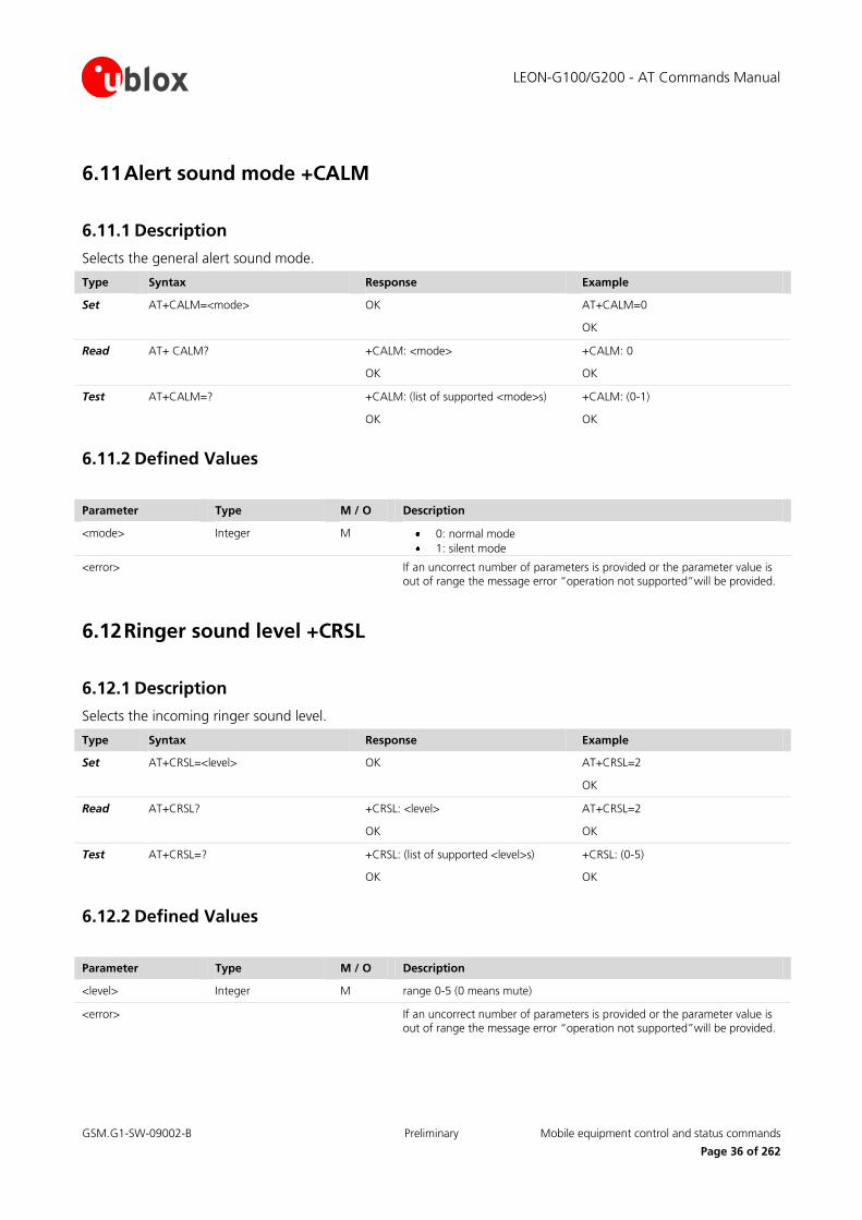
LEON-G100/G200 - AT Commands Manual
GSM.G1-SW-09002-B Preliminary Mobile equipment control and status commands
Page 36 of 262
6.11 Alert sound mode +CALM
6.11.1 Description
Selects the general alert sound mode.
Type Syntax Response Example
Set AT+CALM=<mode> OK AT+CALM=0
OK
Read AT+ CALM? +CALM: <mode>
OK
+CALM: 0
OK
Test AT+CALM=? +CALM: (list of supported <mode>s)
OK
+CALM: (0-1)
OK
6.11.2 Defined Values
Parameter Type M / O Description
<mode> Integer M 0: normal mode
1: silent mode
<error> If an uncorrect number of parameters is provided or the parameter value is out of range the message error “operation not supported”will be provided.
6.12 Ringer sound level +CRSL
6.12.1 Description
Selects the incoming ringer sound level.
Type Syntax Response Example
Set AT+CRSL=<level> OK AT+CRSL=2
OK
Read AT+CRSL? +CRSL: <level>
OK
AT+CRSL=2
OK
Test AT+CRSL=? +CRSL: (list of supported <level>s)
OK
+CRSL: (0-5)
OK
6.12.2 Defined Values
Parameter Type M / O Description
<level> Integer M range 0-5 (0 means mute)
<error> If an uncorrect number of parameters is provided or the parameter value is out of range the message error “operation not supported”will be provided.

LEON-G100/G200 - AT Commands Manual
GSM.G1-SW-09002-B Preliminary Mobile equipment control and status commands
Page 37 of 262
6.13 Loudspeaker volume level +CLVL
6.13.1 Description
Selects the speech volume.
Type Syntax Response Example
Set AT+ CLVL =<level> OK AT+CLVL=30
OK
Read AT+ CLVL? + CLVL: <level>
OK
+CLVL: 80
OK
Test AT+ CLVL =? +CLVL: (list of supported <level>s)
OK
+CLVL: (0-100)
OK
6.13.2 Defined Values
Parameter Type M / O Description
<level> Integer M 1-100 (1 means minimum)
<error> If an uncorrect number of parameters is provided or the parameter value is out of range the message error “operation not supported”will be provided.
6.14 Mute control +CMUT
6.14.1 Description
Enables and disables the uplink voice muting during a voice call (only for the active line).
Type Syntax Response Example
Set AT+CMUT=<n> OK AT+CMUT=0
OK
Read AT+CMUT? +CMUT=<n>
OK
+CMUT: 0
OK
Test AT+CMUT=? +CMUT: (list of supported <n>s)
OK
+CMUT: (0-1)
OK
6.14.2 Defined Values
Parameter Type M / O Description
<n> Integer M 0: mute off
1: mute on
<error> If an uncorrect number of parameters is provided or the parameter value is out of range the message error “operation not supported”will be provided.

LEON-G100/G200 - AT Commands Manual
GSM.G1-SW-09002-B Preliminary Mobile equipment control and status commands
Page 38 of 262
6.15 Call meter maximum event +CCWE
6.15.1 Description
Allows sending an URC +CCWV to DTE, when enabled. The syntax of the URC is: +CCWV. The warning is issued when approximately 30 seconds call time remains. It is also sent when starting a call if less than 30 seconds call
time remains.
Type Syntax Response Example
Set AT+CCWE=<mode> OK AT+CCWE=1
OK
Read AT+CCWE? +CCWE: <mode>
OK
+CCWE: 0
OK
Test AT+CCWE=? +CCWE: (list of supported <mode>s)
OK
+CCWE: (0-1)
OK
URC +CCWV
6.15.2 Defined Values
Parameter Type M / O Description
<mode> Integer M 0: disable the call meter warning event
1: enable the call meter warning event
6.16 Set greeting text +CSGT
6.16.1 Description
Sets and activates the greeting text. The greeting text is shown in the MT display when the MT is turned on. The
command can also deactivate a text.
Type Syntax Response Example
Set AT+CSGT=<mode>[,<text>] OK AT+CSGT=1,”Hello user”
OK
Read AT+CSGT? +CSGT: <text>,<mode>
OK
+CSGT: "Hello",0
OK
Test AT+CSGT=? +CSGT: (list of <mode>s),<ltext>
OK
+CSGT: (0-1),49
OK

LEON-G100/G200 - AT Commands Manual
GSM.G1-SW-09002-B Preliminary Mobile equipment control and status commands
Page 39 of 262
6.16.2 Defined Values
Parameter Type M / O Description
<text> String Contains the greeting text
<mode> Integer M 0: turn off greeting text
1: turn on greeting text
<ltext> Integer M Maximum length of <text>
The greeting message setting is saved in NVM after power off if changed.
6.17 Automatic Time Zone Update +CTZU
6.17.1 Description
Enables and disables automatic time zone update via NITZ.
Type Syntax Response Example
Set AT+CTZU=<onoff> OK AT+CTZU=1
OK
Read AT+CTZU? +CTZU: <onoff>
OK
+CTZU: 0
OK
Test AT+CTZU=? +CTZU: (list of supported <onoff>s)
OK
+CTZU: (0-1)
OK
6.17.2 Defined Values
Parameter Type M / O Description
<onoff> Integer M 0: disable automatic time zone via NITZ (default value)
1: enable automatic time zone update via NITZ
6.18 Time Zone Reporting +CTZR
6.18.1 Description
Enables and disables time zone change event reporting. If reporting is enabled, the MT returns the URC:+CTZV: <tz> whenever time zone is changed.
Type Syntax Response Example
Set AT+CTZR=<onoff> OK AT+CTZR=1
OK
Read AT+CTZR? +CTZR: <onoff>
OK
+CTZR: 0
OK

LEON-G100/G200 - AT Commands Manual
GSM.G1-SW-09002-B Preliminary Mobile equipment control and status commands
Page 40 of 262
Type Syntax Response Example
Test AT+CTZR=? +CTZR: (list of supported <onoff>s)
OK
+CTZR: (0-1)
OK
URC +CTZV: <tz>
6.18.2 Defined Values
Parameter Type M / O Description
<onoff> Integer M 0: disable time zone change event reporting (default value)
1: enable time zone change event reporting
<tz> Integer M Indicates the time zone
The Time Zone reporting is not affected by the Automatic Time Zone setting command, +CTZU.
6.19 Report mobile termination error +CMEE
6.19.1 Description
Enables or disables the use of result code +CME ERROR: <err> as an indication of an error relating to the functionality of the MT. When enabled, MT related errors cause +CME ERROR: <err> final result code instead of
the regular ERROR final result code. ERROR is returned normally when error is related to syntax, invalid
parameters or MT functionality.
Type Syntax Response Example
Set AT+CMEE=[<n>] OK AT+CMEE=2
OK
Read AT+CMEE? +CMEE: <n>
OK
+CMEE: 0
OK
Test AT+CMEE=? +CMEE: (list of supported <n>s)
OK
+CMEE: (0-2)
OK
6.19.2 Defined Values
Parameter Type M / O Description
<n> Integer M 0: disable +CME ERROR: <err> result code and use ERROR instead
1: enable +CME ERROR: <err> result code and use numeric <err> values
2: enable +CME ERROR: <err> result code and use verbose <err> values
When +CMEE=2 selected, the following convention is valid:
If the error code is related to a parameter not covered by the GSM/ETSI or u-blox specification,
the value <error>="operation not supported" shall be used
If the MT is in a state which does not allow performing the entered command, the value
<error>="operation not allowed" shall be used

LEON-G100/G200 - AT Commands Manual
GSM.G1-SW-09002-B Preliminary Mobile equipment control and status commands
Page 41 of 262
6.20 List all available AT commands +CLAC
6.20.1 Description
Causes the MT to return one or more lines of AT commands that are available for the DTE user. Each line contains one AT command.
Type Syntax Response Example
Action AT+CLAC <AT command 1>
[<AT command 2>
[…]]
OK
Test AT+CLAC=? OK
6.20.2 Defined Values
Parameter Type M / O Description
<AT command> String AT command name

LEON-G100/G200 - AT Commands Manual
GSM.G1-SW-09002-B Preliminary Call control commands
Page 42 of 262
7 Call control commands
7.1 Select type of address +CSTA
7.1.1 Description
Selects the type of number for further dialling commands (D) according to 3GPP specifications.
Because the type of address is automatically detected on the dial string of the D command, the +CSTA
command has really no effect.
Type Syntax Response Example
Set AT+CSTA=[<type>] OK AT+CSTA=145
OK
Read AT+CSTA? +CSTA: <type>
OK
+CSTA: 145
OK
Test AT+CSTA=? +CSTA: (list if supported <type>s)
OK
+CSTA: (129,145)
OK
7.1.2 Defined Values
Parameter Type M / O Description
<type> Integer M 145: when dialing string includes international access code character “+”
129: national coded dialing string
7.2 Dial command D
7.2.1 Description
Lists characters that may be used in a dialling string for making a call (voice, data or fax call) or controlling
supplementary services in accordance with [15] and initiates the indicated kind of call. No further commands may follow in the command line in case of data or fax calls. The command is abortable by hitting a key.
If the semicolon “;” is given after the phone number, a voice call is originated, regardless of the value set via +FCLASS command; otherwise the kind of call depends on the service class previously selected via
+FCLASS command.
Type Syntax Response Example

LEON-G100/G200 - AT Commands Manual
GSM.G1-SW-09002-B Preliminary Call control commands
Page 43 of 262
Type Syntax Response Example
Action ATD<number>[<I>][<G>][;] See 7.2.3 “Responses” (Voice Call)
ATD123456;
OK
(Data / Fax Call)
ATD123456
CONNECT 9600
(Supplementary Services)
ATD*#43#
+CCWA: 0,1
+CCWA: 0,2
+CCWA: 0,4
OK
7.2.2 Defined Values
Parameter Type M / O Description
<number> Integer M Phone number; the allowed phone digits are the V.25ter dialing digits 1, 2, 3, 4, 5, 6, 7, 8, 9, 0, *,#, +, A, B, C. Character D is allowed but ignored).
“,”, “T”, “P”, “!”, “W” or “@” are ignored
<I> String Set the CLI status; allowed values are:
I (ASCII code 49 Hex): restrict CLI presentation
i: allow CLI presentation
CLIR supplementary service subscription is
overridden for this call.
<G> String Enable / disable the CUG supplementary service for the specific call; allowed values are:
G: activate CUG;
g: deactivate CUG.
The index and the information parameters used dunring the call will be the same previously set with +CCUG command (pelase refer to chapter 12.16).
<data rate> Integer M Refer to command +CBST (refer to paragraph 7.2.3 “Responses”)
In case of data/fax call, refer to “Circuit 108/2, +++
behavior for the different &D: summarizing table” (chapter 15.4.4) to return in Command Mode and
disconnect the call.
7.2.3 Responses
The following table lists the possible responses to the command. The response is formated using the ATV
command (for more details see chapter 15.31).
Verbose Numeric Description
OK 0 Acknowledges successful execution of the command

LEON-G100/G200 - AT Commands Manual
GSM.G1-SW-09002-B Preliminary Call control commands
Page 44 of 262
Verbose Numeric Description
CONNECT 1 A connection has been established
NO CARRIER 3 The connection has been terminated from the remote part or the attempt to establish a connection failed
ERROR 4 General failure
BUSY 7 Engaged signal detected (the called number is busy)
NO ANSWER 8 If no hang up is detected after a fixed network timeout
CONNECT<data rate> 9 Same as CONNECT but includes the data rate (data call)
7.2.4 Voice Call Example
The following diagram illustrates the possible transitions in both Mobile Terminated and Mobile Originated calls.
Responses and result codes generated by MT are in italic.
MT
AT+CLIP=1; +CRC=1OK
+CRING: VOICE
+CLIP:+35812345,145
ATA
MO without COLP
AT+COLP=0OK
ATD12345;
MO with COLP
AT+COLP=1OK
ATD12345;
General failureERROR
Call setup startedOK
Connection FailureNO CARRIERAT CEER
+CEER: failure causeOK
Remote Busy
BUSY
General Failure
ERROR
SuccessOK
Connection FailureNO CARRIERAT CEER
+CEER: failure causeOK
Connection FailureNO CARRIERAT CEER
+CEER: failure causeOK
VOICE call active
remotehangup
AT+CHUP(ot ATH or
drop DTR)
NO CARRIER OK
(remote ring or other network generated tones)
(no indication on successful call setup)
Success+COLP: +35812345,145OK
7.3 Direct calling from phonebooks D>
7.3.1 Description
Allows voice, data or fax calls, selecting the phone number from the phonebook.
If the semicolon “;” is given after the phone number, a voice call is originated, regardless of the value
set via +FCLASS command; otherwise the kind of call depends on the service class previously selected via
+FCLASS command.

LEON-G100/G200 - AT Commands Manual
GSM.G1-SW-09002-B Preliminary Call control commands
Page 45 of 262
Type Syntax Response Example
Action ATD><str>[I][G][;] See 7.2.3 “Responses” ATD>"u-blox ";
OK
ATD><mem><n>[I][G][;] See 7.2.3 “Responses” ATD>SM1;
OK
ATD><n>[I][G][;] See 7.2.3 “Responses” ATD>1;
OK
7.3.2 Defined Values
Parameter Type M / O Description
<str> String D><str>[I][G][;] originates a call to phone number with corresponding alphanumeric field in the phonebook (set via +CPBS command; more details in chapter 10.1) is <str>.
<mem><n> String D><mem><n>[I][G][;] originates a call to phone number in memory (one of the phonebooks) <mem> entry location <n>; refer to +CPBS command (chapter 10.1) for <mem> value.
<mem> value must be inserted without “”.
<n> String D><n>[I][G][;] originate a call to phone number in entry location <n> of the phonebook (set via +CPBS command; more details in chapter 10.1).
[I][G][;] String Refer to paragraph 7.2 “Dial command D”
7.4 Select tone dialling T
7.4.1 Description
Causes subsequent (or previous) D command to assume that DTMF dialling is to be used. Because in GSM DTMF dialling is default, this command has no effect.
Type Syntax Response Example
Action ATT OK
7.5 Select pulse dialling P
7.5.1 Description
Causes subsequent (or previous) D command to assume that pulse dialling is to be used. Because in GSM DTMF
dialling is default, this command has no effect.
Type Syntax Response Example
Action ATP OK

LEON-G100/G200 - AT Commands Manual
GSM.G1-SW-09002-B Preliminary Call control commands
Page 46 of 262
7.6 Call answer A
7.6.1 Description
Instructs the DCE to immediately connect to line and start the answer sequence as specified for the underlying DCE. Any additional command that appears after A on the same command line is ignored. The command is
abortable. The user is informed that an incoming call is waiting, by the information result code RING or +CRING:
<type> (refer to chapter 13.5) displayed on MT.
Type Syntax Response Example
Action ATA RING
OK
7.7 Hook control H
7.7.1 Description
Disconnects the remote user. In case of multiple calls, call is released, except for waiting or held calls.
In case of dual service calls ATH will modify the data part of the call to the voice part, fax is not affected. If the module is GPRS context activated in On-Line Command Mode (OLCM) the ATH command deactivates the
context. During the GPRS OLCM an incoming CS call can be accepted with a ATA command (chapter 7.6).
Subsequent ATH command releases the current CS call while leaving the GPRS context activated. In this state a second ATH command also deactivates the GPRS context.
Type Syntax Response Example
Action ATH OK
7.8 Monitor speaker loudness L
7.8.1 Description
Controls the volume of the monitor speaker. It has no effect.
Type Syntax Response Example
Action ATL<value> OK
7.8.2 Defined Values
Parameter Type M / O Description
<value> Integer M 0-3

LEON-G100/G200 - AT Commands Manual
GSM.G1-SW-09002-B Preliminary Call control commands
Page 47 of 262
7.9 Monitor speaker mode M
7.9.1 Description
Controls when the monitor speaker is on. The command has no effect.
Type Syntax Response Example
Action ATM<value> OK
7.9.2 Defined Values
Parameter Type M / O Description
<value> Integer M 0-2
7.10 Call mode +CMOD
7.10.1 Description
Selects the call mode of further dialing commands (D) or for next answering command (A).
Type Syntax Response Example
Set AT+CMOD=<mode> OK AT+CMOD=0
OK
Read AT+CMOD? +CMOD: <mode>
OK
+CMOD: 0
OK
Test AT+ CMOD =? +CMOD: (list of supported <mode>s)
OK
+CMOD: (0-1)
OK
7.10.2 Defined Values
Parameter Type M / O Description
<mode> Integer M 0: single mode
1: TS61 (voice alternating with fax)
TS means Tele Service.
7.11 Hang up call +CHUP
7.11.1 Description
Causes the MT to hang up the current GSM call.
All active calls will be released but neither waiting nor held calls.

LEON-G100/G200 - AT Commands Manual
GSM.G1-SW-09002-B Preliminary Call control commands
Page 48 of 262
Type Syntax Response Example
Action AT+CHUP OK
Test AT+CHUP=? OK
7.12 Extended error report +CEER
7.12.1 Description
Causes the MT to return one or more lines of information text <report>, determined by the MT manufacturer,
which offer an extended report of the reason for:
The failure in the last unsuccessful call setup or in-call modification;
The last call release;
The last unsuccessful GPRS attach or unsuccessful PDP context activation;
The last GPRS detach or PDP context deactivation.
Type Syntax Response Example
Action AT+CEER +CEER: <report>
OK
+CEER: normal, NO CARRIER
OK
Test AT+CEER=? OK
7.12.2 Defined Values
Parameter Type M / O Description
<report> String The total number of characters, including line terminators, in the information text does not exceed 2041. The <report> text is the failure cause from [12].
7.13 Single numbering scheme +CSNS
7.13.1 Description
Selects the bearer or teleservice to be used when mobile terminated single numbering scheme call is established.
Parameter values set with +CBST command shall be used when <mode> equals to a data service.
The behavior of this command is strictly dependant from the network service.
Test command returns values supported as compound values.
Before setting +CSNS to 4 (data), the bearer capability to be sent to the network must be defined with
AT+CBST command (e.g. AT+CBST=0,0,1) (please refer to chapter 13.1).
Type Syntax Response Example
Set AT+CSNS=<mode> OK AT+CSNS=0
OK

LEON-G100/G200 - AT Commands Manual
GSM.G1-SW-09002-B Preliminary Call control commands
Page 49 of 262
Type Syntax Response Example
Read AT+CSNS? +CSNS: <mode>
OK
+CSNS: 0
OK
Test AT+CSNS=? +CSNS: (list of supported <mode>s)
OK
+CSNS: (0,2,4)
OK
7.13.2 Defined Values
Parameter Type M / O Description
<mode> Integer M 0: voice
2: fax (TS 62)
4: data
TS means Tele Service.
7.14 Tone duration +VTD
7.14.1 Description
Refers to an integer <n> that defines the length of tones emitted as a result of the +VTS command. In GSM the value of tone duration is preset and cannot be altered.
Type Syntax Response Example
Set AT+VTD=[<n>] OK AT+VTD=2
OK
Read AT+VTD? +VTD: <n>
OK
+VTD: 1
OK
Test AT+VTD=? +VTD: (list of supported <n>s)
OK
+VTD: (0-255)
OK
7.14.2 Defined Values
Parameter Type M / O Description
<n> Integer M Integer value in the range of 0 to 255. A value different than zero causes a tone of duration <n>/10 seconds. The value 1 is default. If the value 0 is selected, the tone duration is set to 1/10 seconds.
7.15 DTMF and tone generation +VTS
7.15.1 Description
Allows transmission of DTMF tones. These tones may be used e.g. when announcing the start of a recording period. In GSM this operates only in voice mode. If the optional parameter <duration> is left out, the tone
duration is given by the setting +VTD (see +VTD description). The command is abortable hitting a key, not
covered by the 3GPP specification.

LEON-G100/G200 - AT Commands Manual
GSM.G1-SW-09002-B Preliminary Call control commands
Page 50 of 262
Type Syntax Response Example
Set AT+VTS=<DTMF>[,<duration>] OK AT+VTS=2
OK
or
AT+VTS=2,10
OK
Test AT+VTS=? +VTS: (list of <DTMF>s),(list of supported <duration>s)
OK
+VTS: (0-9,#,*,A-D),(0-255)
OK
7.15.2 Defined Values
Parameter Type M / O Description
<DTMF> Integer M Single ASCII character in the set 0-9, #, *, A-D.
<duration> Integer M Integer value in the range 0-255, expressed in dozen of msec. This parameters is ignored.
7.16 Redial last telephone number DL
7.16.1 Description
Redials the last number used in the ATD command. This command is abortable.
This command is applicable only for voice calls.
Type Syntax Response Example
Action ATDL OK
7.17 Automatic answer S0
7.17.1 Description
Controls the automatic answering feature of the DCE. If set to 0, automatic answering is disabled, otherwise it
causes the DCE to answer when the incoming call indication (RING) has occurred the number of times indicated
by the value.
Type Syntax Response Example
Set ATS0=<value> OK ATS0=2
OK
Read ATS0? <value>
OK
000
OK
7.17.2 Defined Values
Parameter Type M / O Description
LEON-G100/G200 - AT Commands Manual
GSM.G1-SW-09002-B Preliminary Call control commands
Page 51 of 262
Parameter Type M / O Description
<DTMF> Integer M Single ASCII character in the set 0-9, #, *, A-D.
<value> Integer M Value in the range 0-255; in the read answer <value> is "xxx" format
Default setting: S0=0, (automatic answering is disabled)

LEON-G100/G200 - AT Commands Manual
GSM.G1-SW-09002-B Preliminary Network service commands
Page 52 of 262
8 Network service commands
8.1 Subscriber number +CNUM
8.1.1 Description
Returns the MSISDNs related to this subscriber. If the subscriber has different MSISDN for different services, each
MSISDN is returned in a separate line.
Type Syntax Response Example
Action AT+CNUM +CNUM: [<alpha1>],<number1>,<type1>
[+CNUM: [<alpha2>],<number2>,<type2>
[...]]
OK
or
OK
+CNUM: “Mario Rossi”,”+39320821708”,145 +CNUM: “ABCD . AAA”,”123456789012”,129
OK
Test AT+CNUM=? OK
8.1.2 Defined Values
Parameter Type M / O Description
<alphax> String Optional alphanumeric string associated with <numberx>; used character set is selected by setting +CSCS (refer to chapter 5.5)
<numberx> String String type phone number of format specified by <typex>
<typex> Integer M Type of address octet in integer format (145 when <numberx> string includes “+”, otherwise 129)
8.2 Signal quality +CSQ
8.2.1 Description
Returns signal strength indication <rssi> and channel bit error rate <ber> from the MT. The radio signal strength
<rssi> will be also used to build and display the indicator “signal” i.e. signal quality in the response code +CIND
(refer to chapter 6.5) and in the URC +CIEV (refer to chapter 6.6).
The following mapping of “signal” to <rssi> exists:
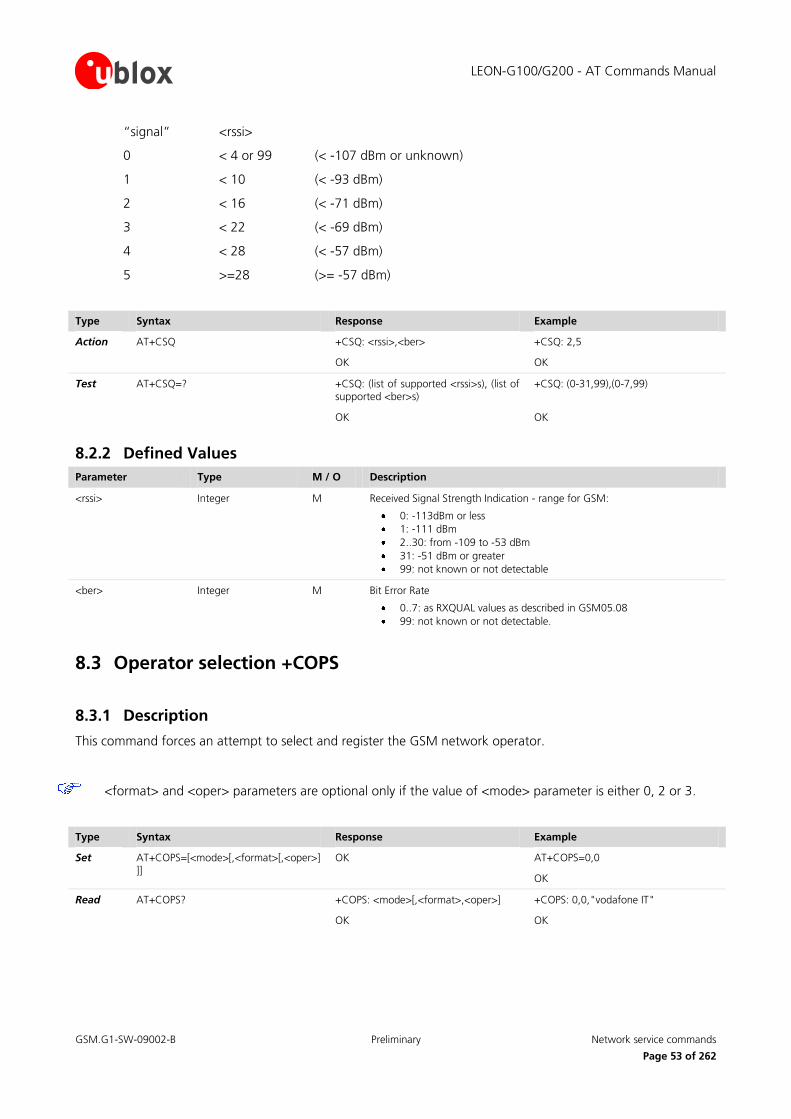
LEON-G100/G200 - AT Commands Manual
GSM.G1-SW-09002-B Preliminary Network service commands
Page 53 of 262
“signal” <rssi>
0 < 4 or 99 (< -107 dBm or unknown)
1 < 10 (< -93 dBm)
2 < 16 (< -71 dBm)
3 < 22 (< -69 dBm)
4 < 28 (< -57 dBm)
5 >=28 (>= -57 dBm)
Type Syntax Response Example
Action AT+CSQ +CSQ: <rssi>,<ber>
OK
+CSQ: 2,5
OK
Test AT+CSQ=? +CSQ: (list of supported <rssi>s), (list of supported <ber>s)
OK
+CSQ: (0-31,99),(0-7,99)
OK
8.2.2 Defined Values
Parameter Type M / O Description
<rssi> Integer M Received Signal Strength Indication - range for GSM:
0: -113dBm or less
1: -111 dBm
2..30: from -109 to -53 dBm
31: -51 dBm or greater
99: not known or not detectable
<ber> Integer M Bit Error Rate
0..7: as RXQUAL values as described in GSM05.08
99: not known or not detectable.
8.3 Operator selection +COPS
8.3.1 Description
This command forces an attempt to select and register the GSM network operator.
<format> and <oper> parameters are optional only if the value of <mode> parameter is either 0, 2 or 3.
Type Syntax Response Example
Set AT+COPS=[<mode>[,<format>[,<oper>]]]
OK AT+COPS=0,0
OK
Read AT+COPS? +COPS: <mode>[,<format>,<oper>]
OK
+COPS: 0,0,"vodafone IT"
OK

LEON-G100/G200 - AT Commands Manual
GSM.G1-SW-09002-B Preliminary Network service commands
Page 54 of 262
Type Syntax Response Example
Test AT+COPS=? +COPS: [list of supported (<stat>),long alphanumeric <oper>, short alphanumeric <oper>, numeric <oper>)s[,(list of supported <mode>s),(list of supported <format>s)]]
OK
+COPS: (2,"vodafone IT","voda IT","22210"),(1,"SI vodafone","vodafone SI","29340"),(1,"I WIND","I WIND","22288"),(1,"I TIM","TIM","22201"),(1,"MOBITEL","MOBITEL","29341"),,(0-4),(0-2)
OK
8.3.2 Defined Values
Parameter Type M / O Description
<mode> Integer M Is used to select whether the selection is done automatically by the MT or is forced by this command to operator <oper> given in the format <format>:
0: automatic (<oper> field is ignored) (default value)
1: manual
2: deregister from network
3: set only <format>
4: manual/automatic (if manual selection fails, automatic mode is entered)
<format> Integer M 0: long alphanumeric <oper>
1: short format alphanumeric <oper>
2: numeric <oper>
<oper> String Given in format <format>; this field may be up to 16 character long for long alphanumeric format, up to 8 characters for short alphanumeric format and 5 characters long for numeric format (MCC/MNC codes)
<stat> Integer M 0: unknown
1: available
2: current
3: forbidden
if <mode>= 0 only one parameter will be saved in the profile while the PLMN will be not stored. If the MT
is set in normal mode PLMN information will be stored in the profile.
The application/user should not rely on the Set command response “OK” as a confirmation that the
network selection has been performed. To determine the network registration status, rely on the URC +CREG (refer to chapter 8.4).
Example
AT+COPS=1,2
OK
This doesn’t mean the module is currently registered to the given PLMN
+CREG: 5
After this the module is finally registered (roaming in this case)

LEON-G100/G200 - AT Commands Manual
GSM.G1-SW-09002-B Preliminary Network service commands
Page 55 of 262
8.4 Network registration +CREG
8.4.1 Description
Controls the presentation of an URC +CREG: <stat> when <n>=1 and there is a change in the MT network registration status, or code +CREG: <stat>[,<lac>,<ci>] when <n>=2 and there is a change of the network cell.
Type Syntax Response Example
Set AT+CREG=[<n>] OK AT+CREG=1
OK
Read AT+CREG? +CREG: <n>, <stat>[,<lac>,<ci>]
OK
+CREG: 0,0
OK
Test AT+CREG=? +CREG: (list of the supported <n>s)
OK
+CREG: (0-2)
OK
URC +CREG: <stat>[,<lac>,<ci>] +CREG: 1,"4E54","44A5"
8.4.2 Defined Values
Parameter Type M / O Description
<n> Integer M 0: disable network registration URC (default value)
1: enable network registration URC CREG: <stat>
2: enable network registration and location information URC +CREG: <stat>[,<lac>,<ci>]
<stat> Integer M 0: not registered, MT is not currently searching a new operator to register to
1: registered, home network
2: not registered, but MT is currently searching a new operator to register to
3: registration denied
4: unknown
5: registered, roaming
<lac> String two bytes location area code in hexadecimal format (e.g. “00C3”)
<ci> String two bytes cell ID in hexadecimal format (e.g. “A13F”)
8.5 Preferred operator list +CPOL
8.5.1 Description
Edits the SIM preferred list of networks and writes an entry in the SIM list of preferred operators. If no list has been selected, the default SIM file EFPLMNwAcT is used. If Operator controlled PLMN selector with Access
Technology EFOPLMNwAcT or HPLMN selector with Access Technology EFHPLMNwAcT is selected, +CPOL is not
allowed to write in this sector (see [19]).
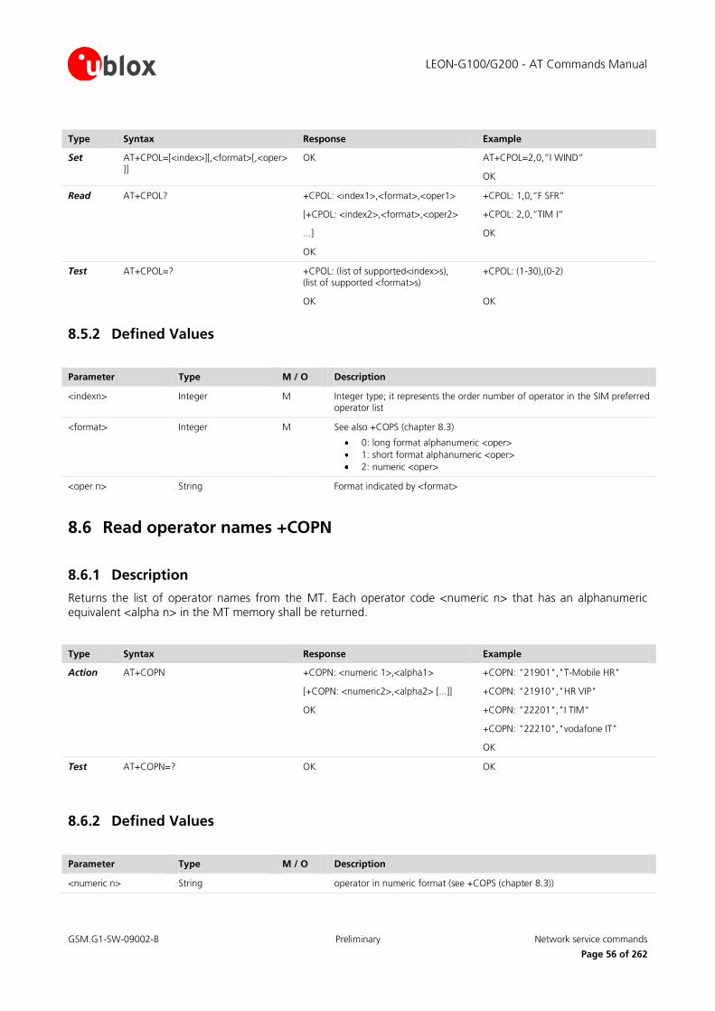
LEON-G100/G200 - AT Commands Manual
GSM.G1-SW-09002-B Preliminary Network service commands
Page 56 of 262
Type Syntax Response Example
Set AT+CPOL=[<index>][,<format>[,<oper>]]
OK AT+CPOL=2,0,”I WIND”
OK
Read AT+CPOL? +CPOL: <index1>,<format>,<oper1>
[+CPOL: <index2>,<format>,<oper2>
...]
OK
+CPOL: 1,0,”F SFR”
+CPOL: 2,0,”TIM I”
OK
Test AT+CPOL=? +CPOL: (list of supported<index>s), (list of supported <format>s)
OK
+CPOL: (1-30),(0-2)
OK
8.5.2 Defined Values
Parameter Type M / O Description
<indexn> Integer M Integer type; it represents the order number of operator in the SIM preferred operator list
<format> Integer M See also +COPS (chapter 8.3)
0: long format alphanumeric <oper>
1: short format alphanumeric <oper>
2: numeric <oper>
<oper n> String Format indicated by <format>
8.6 Read operator names +COPN
8.6.1 Description
Returns the list of operator names from the MT. Each operator code <numeric n> that has an alphanumeric equivalent <alpha n> in the MT memory shall be returned.
Type Syntax Response Example
Action AT+COPN +COPN: <numeric 1>,<alpha1>
[+COPN: <numeric2>,<alpha2> [...]]
OK
+COPN: "21901","T-Mobile HR"
+COPN: "21910","HR VIP"
+COPN: "22201","I TIM"
+COPN: "22210","vodafone IT"
OK
Test AT+COPN=? OK OK
8.6.2 Defined Values
Parameter Type M / O Description
<numeric n> String operator in numeric format (see +COPS (chapter 8.3))
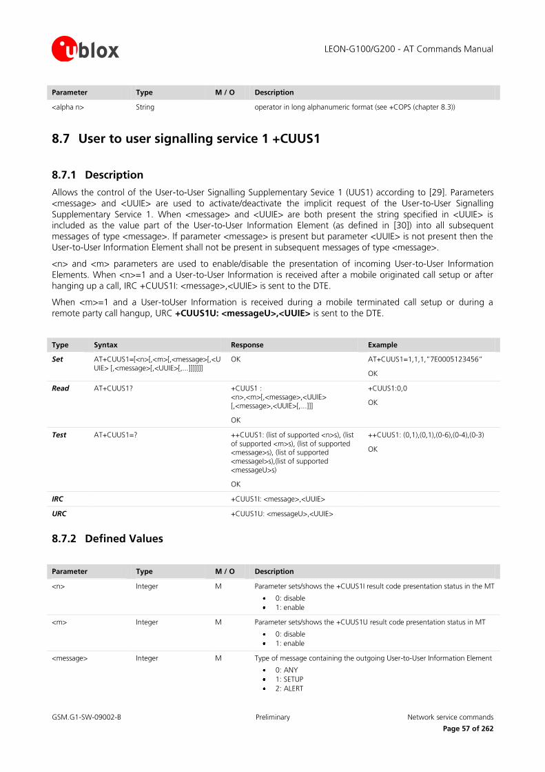
LEON-G100/G200 - AT Commands Manual
GSM.G1-SW-09002-B Preliminary Network service commands
Page 57 of 262
Parameter Type M / O Description
<alpha n> String operator in long alphanumeric format (see +COPS (chapter 8.3))
8.7 User to user signalling service 1 +CUUS1
8.7.1 Description
Allows the control of the User-to-User Signalling Supplementary Sevice 1 (UUS1) according to [29]. Parameters
<message> and <UUIE> are used to activate/deactivate the implicit request of the User-to-User Signalling
Supplementary Service 1. When <message> and <UUIE> are both present the string specified in <UUIE> is included as the value part of the User-to-User Information Element (as defined in [30]) into all subsequent
messages of type <message>. If parameter <message> is present but parameter <UUIE> is not present then the
User-to-User Information Element shall not be present in subsequent messages of type <message>.
<n> and <m> parameters are used to enable/disable the presentation of incoming User-to-User Information
Elements. When <n>=1 and a User-to-User Information is received after a mobile originated call setup or after
hanging up a call, IRC +CUUS1I: <message>,<UUIE> is sent to the DTE.
When <m>=1 and a User-toUser Information is received during a mobile terminated call setup or during a
remote party call hangup, URC +CUUS1U: <messageU>,<UUIE> is sent to the DTE.
Type Syntax Response Example
Set AT+CUUS1=[<n>[,<m>[,<message>[,<UUIE> [,<message>[,<UUIE>[,...]]]]]]]
OK AT+CUUS1=1,1,1,”7E0005123456”
OK
Read AT+CUUS1? +CUUS1 : <n>,<m>[,<message>,<UUIE> [,<message>,<UUIE>[,...]]]
OK
+CUUS1:0,0
OK
Test AT+CUUS1=? ++CUUS1: (list of supported <n>s), (list of supported <m>s), (list of supported <message>s), (list of supported <messageI>s),(list of supported <messageU>s)
OK
++CUUS1: (0,1),(0,1),(0-6),(0-4),(0-3)
OK
IRC +CUUS1I: <message>,<UUIE>
URC +CUUS1U: <messageU>,<UUIE>
8.7.2 Defined Values
Parameter Type M / O Description
<n> Integer M Parameter sets/shows the +CUUS1I result code presentation status in the MT
0: disable
1: enable
<m> Integer M Parameter sets/shows the +CUUS1U result code presentation status in MT
0: disable
1: enable
<message>
Integer M Type of message containing the outgoing User-to-User Information Element
0: ANY
1: SETUP
2: ALERT

LEON-G100/G200 - AT Commands Manual
GSM.G1-SW-09002-B Preliminary Security commands
Page 58 of 262
Parameter Type M / O Description
3: CONNECT
4: DISCONNECT
5: RELEASE
6: RELEASE_COMPLETE
<messageI> Integer M Type of message containing the intermediate User-to-User Information Element
0: ANY
1: ALERT
2: PROGRESS
3: CONNECT (sent after +COLP if enabled)
4: RELEASE
<messageU> Integer M Type of message containing the unsollicited User-to-User Information Element
0: ANY
1: SETUP (returned after +CLIP if presented, otherwise after every RING or +CRING (refer to chapter 13.4))
2: DISCONNECT
3: RELEASE_COMPLETE
<UUIE> Integer M The User-user Information Element (as defined in [12]) in hexadecimal character format (for hexadecimal format, refer +CSCS, chapter 13.4).
If the MT does not distinguish the type of message containing the User-to-user Information Element, it can use the value for ANY message.
9 Security commands
9.1 Enter PIN +CPIN
9.1.1 Description
Sends to the MT a password which is necessary before it can be operated. If no PIN request is pending, no action
is taken towards MT and an corresponding error code is returned. If PIN is inserted in wrong mode for three times, PUK must be inserted with this syntax: AT+CPIN="SIM PUK",”<newpin>; this second pin, <newpin>,
replaces the old pin in the SIM.
Type Syntax Response Example
Set AT+CPIN=<pin>[,<newpin>] +CME ERROR: SIM PIN
OK
AT+CPIN=”0933”
OK
AT+CPIN="240xxxxx", "2345"
where 240xxxxx= SIM PUK
2345=new SIM PIN
Read AT+CPIN? +CPIN: <code>
OK
+CPIN: SIM PIN
OK
Test AT+CPIN=? OK
LEON-G100/G200 - AT Commands Manual
GSM.G1-SW-09002-B Preliminary Security commands
Page 59 of 262
9.1.2 Defined Values
Parameter Type M / O Description
<pin>, <newpin> String
<code> String READY: MT is not pending for any password
SIM PIN: MT is waiting SIM PIN to be given
SIM PUK: MT is waiting SIM PUK to be given
SIM PIN2: MT is waiting SIM PIN2 to be given
SIM PUK2: MT is waiting SIM PUK2 to be given
If PIN is not inserted the following situation can
occur:
AT+CMEE=2
OK
AT+COPS=0
+CME ERROR: SIM PIN required
AT+CMEE=0
OK
AT+COPS=0
ERROR
Note:
If PIN is not inserted the following situation can occour:
AT+CMEE=2
OK
AT+COPS=0
+CME ERROR: SIM PIN required
AT+CMEE=0
OK
AT+COPS=0
ERROR
9.2 Facility lock +CLCK
9.2.1 Description
Used to lock, unlock or interrogate a MT or a network facility <fac>. Password is normally needed to do such actions. When querying the status of a network service (<mode>=2) the response line for “not active” case
(<status>=0) should be returned only if service is not active for any <class>. The command is abortable if
network facilities are set or interrogated.
For <fac> "PN", "PU", "PP" and "PC" only <mode>=0 and <mode>=2 (unlock and query status) are
supported.

LEON-G100/G200 - AT Commands Manual
GSM.G1-SW-09002-B Preliminary Security commands
Page 60 of 262
Type Syntax Response Example
Set AT+CLCK=<fac>,<mode>[,<passwd>[,<class>]]
OK
or
+CLCK: <status>[,<class1>
[+CLCK: <status>[,<class1>
[…]]
AT+CLCK=”SC”,1,”0933”
OK
Test AT+CLCK=? +CLCK: (list of supported <fac>s)
OK
+CLCK: ("SC","PN","PU","PP","PC","FD","AO","OI", "OX","AI","IR","AB","AG","AC")
OK

LEON-G100/G200 - AT Commands Manual
GSM.G1-SW-09002-B Preliminary Security commands
Page 61 of 262
9.2.2 Defined Values
Parameter Type M / O Description
<fac> String facility values
“SC”: SIM (lock SIM card)
"PN": Network Personalisation (refer to [31])
"PU" : network sUbset Personalisation (refer to [31])
"PP" : service Provider Personalisation (refer to [31])
"PC" : Corporate Personalisation (refer to [31])
"FD": SIM fixed dialling memory feature (if PIN2 authentication has not been done during the current session, PIN2 is required as <passwd>)
“AO”: BAR (Bar All Outgoing Calls)
“OI” : BOIC (Bar Outgoing International Calls)
“OX” : BOIC-exHC(Bar Outgoing International Calls except to Home Country)
“AI”: BAIC (Bar All Incoming Calls)
“IR”: BIC-Roam (Bar Incoming Calls when Roaming outside the home country)
“AB”: All Barring services (applicable only for <mode>=0)
“AG”: All outGoing barring services (applicable only for <mode>=0)
“AC”: All inComing barring services (applicable only for <mode>=0)
<mode> Integer M 0: unlock
1: lock
2: query status
<status> Integer M 0: not active
1: active
<passwd> String Shall be the same as password specified for the facility from the MT user interface or with command +CPWD (for more details refer to 9.3)
<class x> Integer M Sum of integers each representing a class of information (default 7)
1: voice
2: data
4: FAX
8: short message service
16: data circuit sync
32: data circuit async
64: dedicated packet access
128: dedicated PAD access
9.3 Change password +CPWD
9.3.1 Description
Sets a new password for the facility lock function defined by command +CLCK. The command is abortable
hitting a key.
Type Syntax Response Example
Set AT+CPWD=<fac>,<oldpwd>,<newpwd>
OK AT+CPWD=”SC”,”0933”,”0934”
OK

LEON-G100/G200 - AT Commands Manual
GSM.G1-SW-09002-B Preliminary Security commands
Page 62 of 262
Type Syntax Response Example
Test AT+CPWD=? +CPWD: list of available (<fac>,<pwdlength>s)
OK
+CPWD: ("SC",8),("P2",8),("AO",4),("OI",4),("OX",4), ("AI",4),("IR",4),("AB",4),("AG",4),("AC",4)
OK
9.3.2 Defined Values
Parameter Type M / O Description
<fac> String “P2” SIM PIN2; refer to Facility Lock +CLCK (chapter 0) for other values
<oldpwd> String Contains the old password
<newpwd> String Contains the new password
<pwdlength> Integer M Length of password (digits)
LEON-G100/G200 - AT Commands Manual
GSM.G1-SW-09002-B Preliminary Phonebook commands
Page 63 of 262
10 Phonebook commands
10.1 Select phonebook memory storage +CPBS
10.1.1 Description
Selects a phonebook memory storage for further use in phonebook related commands.
The response to the test command depends on SIM dependent parameters (e.g. "EC").
Type Syntax Response Example
Set AT+CPBS=<storage>[,<password>] OK AT+CPBS=”SM”
OK
Read AT+CPBS? +CPBS: <storage>[,<used>,<total>]
OK
+CPBS: “SM”,25,150
OK
Test AT+CPBS=? +CPBS: (list of supported <storages>s)
OK
+CPBS: ("SM","FD","LD","SN","EC","ON","BL")
OK
10.1.2 Defined Values
Parameter Type M / O Description
<storage> String Represents the phonebook memory storage; the following values are allowed:
“SM”: SIM phonebook
“FD”: SIM fix-dialling phonebook (only valid with PIN2)
“LD”: SIM last-dialling phonebook (read only)
“BN”: SIM barred-dialling-number phonebook (only valid with PIN2)
“SN”: SIM service-dialling-number phonebook (read only)
“EC”: SIM emergency-call-codes phonebook (read only)
“ON”: Own number phone-book (read/write); content is also shown by +CNUM
“BL”: Blacklist phonebook (delete only): only the position 0 is valid
<password> String Represents the PIN2-code required when selecting PIN2-code <storage>s above (e.g. “FD”), if PIN2 is applicable
<used> Integer Indicates the number of used locations in selected memory
<total> > Integer Indicates the total number of locations in selected memory

LEON-G100/G200 - AT Commands Manual
GSM.G1-SW-09002-B Preliminary Phonebook commands
Page 64 of 262
10.2 Read phonebook entries +CPBR
10.2.1 Description
Returns phonebook entries in location number range <index1> ... <index2> from the current phonebook memory storage selected with +CPBS. If <index2> is left out, only location <index1> is returned.
The wildcard character (?) in the phone number of FDN (Fixed Number Phonebook) is allowed.
Type Syntax Response Example
Set AT+CPBR=<index1>[,<index2>] [+CPBR: <index1>,<number>,<type>,<text>]
[...]
[+CPBR: <index2>,<number>,<type>,<text>]
OK
If indexes are filled:
AT+CPBR=1,3
+CPBR: 1,”040123456”,129,”RossiCarlo”
+CPBR: 2,”040123457”,129,”RossiMario”
+CPBR: 3,”040123458”,129,”RossiGiuseppe”
OK
If indexes are not filled:
AT+CPBR=5,6
+CPBR=5,6
OK
Test AT+CPBR=? +CPBR: (list of supported <index>s),<nlength>, <tlength>
OK
+CPBR: (1-100),20,18
OK
10.2.2 Defined Values
Parameter Type M / O Description
<index1>, <index2>, <index>
Integer Values in the range of location numbers of phonebook memory
<number> String Phone number of format <type>
<type> Integer Type of address octet in integer format; default 145 when dialling string includes “+”, otherwise 129
<nlength> Integer Indicates the maximum length of field <number>
<tlength> Integer Indicates the maximum length of field <text>
LEON-G100/G200 - AT Commands Manual
GSM.G1-SW-09002-B Preliminary Phonebook commands
Page 65 of 262
10.3 Find phonebook entries +CPBF
10.3.1 Description
Returns the phonebook entries from the current phonebook (previously selected by +CPBS), alphanumeric field starts with string <findtext>.
The string <findtext> is case sensitive.
Type Syntax Response Example
Set AT+CPBF=<findtext> [+CPBF: <index1>,<number>,<type>,<text>]
[...]
[+CPBF: <index2>,<number>,<type>,<text>]
OK
AT+CPBF=”u-blox”
OK
Test AT+CPBF=? +CPBF: [<nlength>],[<tlength>]
OK
+CPBF: 40,18
OK
10.3.2 Defined Values
Parameter Type M / O Description
<index1>, <index2>, <index>
Integer Values in the range of location numbers of phonebook memory
<number> String Phone number of format <type>
<type> Integer Type of address octet
<findtext>,<text> String Maximum length <tlength>
<nlength> Integer Indicates the maximum length of field <number>
<tlength> Integer Indicates the maximum length of field <text>
10.4 Write phonebook entry +CPBW
10.4.1 Description
Stores phonebook entry in the current phonebook memory storage (selectable with +CPBS) at the location specified by the <index> field. Other entry fields are the phone number <number>; <type> and <text> both
associated to it. If all fields are omitted, except for <index>, the corresponding entry is deleted. If the <index>
field is left out, but the <number> is given, the entry is written in the first free location in the current phonebook memory storage.
If no phonebook entries are available the response to the test command will be +CPBW:0 <CR><LF>OK

LEON-G100/G200 - AT Commands Manual
GSM.G1-SW-09002-B Preliminary Phonebook commands
Page 66 of 262
The following wildcard characters '?' and 'P' are allowed ('*' is DTMF character and hence is not a wildcard character). In ADN, 'P' and 'W' are allowed but 'P' character is allowed before a 'W'. The 'W' character is
the DTMF digit separator: before 'W' there is the number to be dialled; after it DTMF digits will be automatically sent. If in the DTMF sequence there is another 'W' character, then DTMF sequence will pause;
if there is a 'P' character the user will be prompted to choose a digit.
In case of previously selected BL blacklist phonebook, no parameters are needed; <index>=0 is also
accepted.
Set command +CPBW is not applicable for the storages "LD", "SN", "EC" (read only storages).
Type Syntax Response Example
Set AT+CPBW=[<index>][,<number>[,<type>[,<text>]]]
OK AT+CPBW=5,”091137880”,,”u-blox”
OK
Test AT+CPBW=? +CPBW: (list of supported <index>s),<nlength>,(list of supported <type>s),<tlength>
OK
or
+CPBW:0
OK
+CPBW: (1-250),40,(129,145),18
OK
10.4.2 Defined Values
Parameter Type M / O Description
<index> Integer Values in the range of location numbers of phonebook memory
<number> String Phone number of format <type>
<type> Integer Type of address octet; default 145 when dialling string includes “+”, otherwise 129
<text> String Maximum length <tlength>
<nlength> Integer Indicates the maximum length of field <number>
<tlength> Integer Indicates the maximum length of field <text>
LEON-G100/G200 - AT Commands Manual
GSM.G1-SW-09002-B Preliminary Short messages commands
Page 67 of 262
11 Short messages commands
11.1 Select message service +CSMS
11.1.1 Description
Selects message service <service>. It returns the types of messages supported by the MT.
Type Syntax Response Example
Set AT+CSMS=<service> +CSMS:<mt>,<mo>,<bm>
OK
AT+CSMS=1
+CSMS: 1,1,1
OK
Read AT+CSMS? +CSMS: <service>,<mt>,<mo>,<bm>
OK
+CSMS: 0,1,1,1
OK
Test AT+CSMS=? +CSMS: (list of supported <service>s)
OK
+CSMS: (0-1)
OK
11.1.2 Defined Values
Parameter Type M / O Description
<service> Integer 0: Refer to [8] and [9]; the syntax of SMS AT commands is compatible with [16]; phase 2+ features may be supported if no new command syntax is required
1: Refer to [8] and [9]; the syntax of SMS AT commands is compatible with [16]
<mt> Integer Mobile terminated messages
0: not supported
1: supported.
<mo> Integer Mobile originated messages
0: not supported
1: supported.
<bm> Integer Broadcast messages
0: not supported
1: supported.

LEON-G100/G200 - AT Commands Manual
GSM.G1-SW-09002-B Preliminary Short messages commands
Page 68 of 262
11.2 Preferred message storage +CPMS
11.2.1 Description
Selects memory storages <mem1>, <mem2> and <mem3>. If the chosen storage is supported by the MT but not suitable, the final result code +CMS ERROR: <err> should be returned.
”BM” is available only for <mem1>.
Type Syntax Response Example
Set AT+CPMS=<mem1>[,<mem2>[,<mem3>]]
AT+CPMS: <used1>,total1>,<used2>,<total2>, <used3>,<total3>
OK
AT+CPMS=”BM”,”SM”,”SM”
OK
Read AT+CPMS? +CPMS: <mem1>,<used1>,total1>,<mem2>,<used2>, <total2>,<mem3>,<used3>,<total3>
OK
+CPMS: "MT",4,350,"MT",4,350,"MT",4,350
OK
Test AT+CPMS=? +CPMS: (list of supported <mem1>s), (list of supported <mem2>s),(list of supported <mem3>s)
OK
+CPMS: ("MT","ME","SM","BM"),("MT","ME", "SM"),("MT","ME","SM")
OK
11.2.2 Defined Values
Parameter Type M / O Description
<mem1> String "ME" ME message storage
"SM" (U)SIM message storage
"MT" = “ME”+“SM”, “ME” preferred
"BM" broadcast message storage
<mem2> String Memory used to write and send SMS:
"ME" ME message storage
"SM" (U)SIM message storage
"MT" = “ME”+“SM”, “ME” preferred
<mem3> String Memory preferred to store the received SMS:
"ME" ME message storage
"SM" (U)SIM message storage
"MT" = “ME”+“SM”, “ME” preferred
<total1> Integer Total number of message locations in <mem1>
<total2> Integer Total number of message locations in <mem2>
<total3> Integer Total number of message locations in <mem3>
<used1> Integer Number of used message locations in <mem1>
<used2> Integer Number of used message locations in <mem2>
<used3> Integer Number of used message locations in <mem3>

LEON-G100/G200 - AT Commands Manual
GSM.G1-SW-09002-B Preliminary Short messages commands
Page 69 of 262
11.3 Preferred message format +CMGF
11.3.1 Description
Indicates to MT which input and output format of messages shall be used.
Type Syntax Response Example
Set AT+CMGF=[<mode>] OK AT+CMGF=1
OK
Read AT+CMGF? +CMGF: <mode>
OK
+CMGF: 1
OK
Test AT+CMGF=? +CMGF: (list of supported <mode>s)
OK
+CMGF: (0-1)
OK
11.3.2 Defined Values
Parameter Type M / O Description
<mode> Integer Indicates the format of messages used with send, list, read and write commands and URCs resulting from receiving SMS’s messages:
0: PDU mode (default)
1: text mode
11.4 Save settings +CSAS
11.4.1 Description
Saves active message service settings to non-volatile memory (NVRAM). The settings related to +CSCA (the current SMSC address stored in RAM), +CSMP and +CSCB are stored in a profile (only one profile is available).
Type Syntax Response Example
Set AT+CSAS[=<profile>] OK AT+CSAS
OK
Test AT+CSAS=? +CSAS: (list of supported <profile>s)
OK
+CSAS: (0)
OK
11.4.2 Defined Values
Parameter Type M / O Description
<profile> Integer 0: indicates the specific profile number where to store the active message settings

LEON-G100/G200 - AT Commands Manual
GSM.G1-SW-09002-B Preliminary Short messages commands
Page 70 of 262
11.5 Restore Settings +CRES
11.5.1 Description
Restores message service settings from a non-volatile memory (NVRAM) to active memory (RAM). The settings specified in the commands +CSCA (the SMSC address in the SIM card is also updated), +CSMP and +CSCB are
restored (only one profile is available).
Type Syntax Response Example
Set AT+CRES[=<profile>] OK AT+CRES=0
OK
Test AT+CRES=? +CRES: (list of supported <profile>s)
OK
+CRES: (0)
OK
11.5.2 Defined Values
Parameter Type M / O Description
<profile> Integer 0: indicates the specific profile number where to retrieve the message service settings for restoring
11.6 Show text mode parameters +CSDH
11.6.1 Description
Controls whether detailed header information is shown in text mode result codes.
Type Syntax Response Example
Set AT+CSDH=[<show>] OK AT+CSDH=1
OK
Read AT+CSDH? +CSDH: <show>
OK
+CSDH: 0
OK
Test AT+CSDH=? +CSDH: (list of supported <show>s)
OK
++CSDH: (0-1)
OK
11.6.2 Defined Values
Parameter Type M / O Description
<show> Integer 0: do not show detailed header information in text mode result codes
1: show detailed header information in text mode result codes

LEON-G100/G200 - AT Commands Manual
GSM.G1-SW-09002-B Preliminary Short messages commands
Page 71 of 262
11.7 New message indication +CNMI
11.7.1 Description
Selects the procedure to be done to indicate the MT the reception of a new SMS from the network in case of DTR-signal ON. If MT is inactive (DTR-signal OFF), message reception should be done as specified in [7]. All SMS
classes are supported accordingly.
The SMS’s class 0 (normally displayed via MMI), are indicated on DTE via URC +CMTI: “SM”,0 , wherein 0
represents an SMS without SIM-storage (“SM” indicates only that no other specific setting is needed in
order to read the SMS via AT+CMGR=0).
Type Syntax Response Example
Set AT+CNMI=[<mode>[,<mt>[,<bm>[,<ds>[,<bfr>]]]]]
OK AT+CNMI=1,1
OK
Read AT+CNMI? +CNMI=<mode>,<mt>,<bm>,<ds>,<bfr>
OK
+CNMI: 0,0,0,0,0
OK
Test AT+CNMI=? +CNMI: (list of supported <mode>s),(list of supported <mt>s),(list of supported <bm>s),(list of supported <ds>s),(list of supported <bfr>s)
OK
+CNMI: (0-2),(0-3),(0-3),(0-2),(0-1)
OK
URC +CMTI: <mem>,<index>
URC (PDU mode)
+CMT: [<alpha],<length><CR><LF><pdu>
(text mode)
+CMT <oa>,[<alpha>],<scts>[,<tooa>,<fo>,<pid>, <dcs>,<sca>,<tosca>,<length>]
URC +CBMI: <mem>,<index>
URC (PDU mode)
+CBM: <length><CR><LF><pdu>
(text mode)
+CBM: <sn>,<mid>,<dcs>,<page>,<pages><CR><LF> <data>
URC (PDU mode)
+CDS: <length><CR><LF><pdu>
(text mode)
+CDS: <fo>,<mr>,[<ra>],[<tora>],<scts>,<dt>,<st>
URC +CDSI: <mem>,<index>

LEON-G100/G200 - AT Commands Manual
GSM.G1-SW-09002-B Preliminary Short messages commands
Page 72 of 262
11.7.2 Defined Values
Parameter Type M / O Description
<mode> Integer Indicates the format of messages used with send, list, read and write commands and URCs resulting from receiving SMS’s messages:
0: buffer URCs in the MT; if the MT buffer is full, the oldest indication may be discarded and replaced with the new received indications (ring buffer)
1: discard indication and reject new received message URCs when MT-DTE link is reserved; otherwise forward them directly to the DTE
2: buffer URCs in the MT when the serial link is busy (e.g. data-transfer); otherwise forward them directly to the DTE
<mt> Integer Contains the rules for storing received SMS dependent on its <dcs> (SMS Data Coding Scheme (default 0), or Cell Broadcast Data Coding Scheme in integer format)
0: No SMS-DELIVER indications are routed to the TE
1: if SMS-DELIVER is stored in MT, indication of the memory location is routed to the DTE using URC: +CMTI: <mem>,<index>
2: SMS-DELIVER (except class2 SMS) are routed directly to the DTE using the URC: +CMT: [<alpha],<length><CR><LF><pdu> in PDU mode or +CMT <oa>,[<alpha>],<scts>[,<tooa>,,<fo>,<pid>,<dcs>, <sca>,<tosca>,<length>]<CR><LF> If MT has its own display device then class 0 SMS and SMS in the message waiting indication group (discard message) may be copied to both MT display and to DTE. In this case MT shall send the acknowledgement to the network. Class 2 SMSs and messages in the message waiting indication group (storage message) result in indication as defined in <mt>=1
3: Class 3 SMS-DELIVERs are routed directly to DTE using URCs defined in <mt>=2. Messages of other data coding schemes result in indication as defined in <mt>=1.
<bm> Integer Contains the rules for storing CBMs:
0: No CBM indications to the DTE
1 if CBM is stored in RAM/NVRAM by MT, an indication of memory location is routed to DTE URC +CBMI: <mem>,<index>
2: new CBMs are routed directly to the DTE using URC: +CBM: <length><CR><LF><pdu (when PDU-mode enabled> or +CBM: <sn>,<mid>,<dcs>,<page>,<pages><CR><LF><data>
3: Class 3 CBMs are routed directly to DTE using URCs defined in <bm>=2. If CBM storage is supported, messages of other classes result in indication as defined in <bm>=1
<ds> Integer 0: No SMS-STATUS-REPORTs are routed to the DTE
1: SMS-STATUS-REPORTs are routed to the DTE using URC: +CDS: <length><CR><LF><pdu> if PDU mode enabled or +CDS: <fo>,<mr>,[<ra>],[<tora>],<scts>,<dt>,<st> if text mode enabled
2: if SMS-STATUS-REPORT is stored into MT, indication of the memory location is routed to the DTE using the URC +CDSI: <mem>,<index> (<mem> in this case is always "MT")
<bfr> Integer 0: MT buffer of URCs defined within this command is flushed to the DTE when <mode> 1...3 is entered (OK response shall be given before flushing the codes).
1: MT buffer of URCs defined within this command is cleared when <mode> 1...3 is entered

LEON-G100/G200 - AT Commands Manual
GSM.G1-SW-09002-B Preliminary Short messages commands
Page 73 of 262
11.8 Read message +CMGR
11.8.1 Description
Returns the message with location value <index> from message storage <mem1> to the DTE.
The parameters <tooa>,<fo>,<pid>,<dcs>,<sca>,<tosca>,<length>,<cdata> shall be displayed only if
+CSDH=1 is setted.
The syntax AT+CMGR=0 allows to display a SMS class 0 if it is signalized to MT, because no MMI is available in the MT (see also the note from command +CNMI).
Type Syntax Response Example
Set Text mode (+CMGF=1):
AT+CMGR=<index>
(SMS-DELIVER)
+CMGR: <stat>,<oa>,[<alpha>],<scts>[,<tooa>, <fo>,<pid>,<dcs>,<sca>,<tosca>,<length>]
<data>
OK
(SMS-SUBMIT)
+CMGR: <stat>,<da>,[<alpha>][<toda>,<fo>,<pid>,<dcs>,[<vp>],<sca>,<tosca>,<length>]
<data>
OK
(SMS-STATUS-report)
+CMGR:<stat>,<fo>,<mr>,[<ra>],[<tora>]<scts><dt>,<st>
OK
(SMS-COMMAND)
+CMGR: <stat>,<fo>,<ct>[,<pid>,[<mn>],[<da>],[<toda>],<length>
[<cdata>]]
OK
(CBM storage)
+CMGR: <stat>,<sn>,<mid>,<dcs>,<page>,<pages>
<data>
OK
AT+CMGR=303
+CMGR:"REC READ","+393488535999",,"07/04/05,18:02:28+08",145,4,0,0,"+393492000466",145,93
You have a missed called. Free information provided by your operator.
OK
LEON-G100/G200 - AT Commands Manual
GSM.G1-SW-09002-B Preliminary Short messages commands
Page 74 of 262
Type Syntax Response Example
PDU mode (+CMGF=0):
AT+CMGR=<index>
+CMGR: <stat>,[<alpha>],<length>
<pdu>
OK
AT+CMGR=1
+CMGR: 1,,40
0791934329002000040C9193230982661400008070328045218018D4F29CFE06B5CBF379F87C4EBF41E434082E7FDBC3
OK
Test AT+CMGR=? OK
11.8.2 Defined Values
c Type M / O Description
<alpha> String Alphanumeric representation of <da> or <a> corresponding to the entry found in the phonebook [12]. The parameter is not managed.
<index> Integer Index of the message in memory; its range is 0-400; the 0 value is possible only if a SMS class 0 is received and the setting +CNMI=1,… was previously set
Indexes from 1 to n are used for “ME” and from n+1 to n+m for “SM”
<stat> Integer 0: in PDU mode or “REC UNREAD” in text mode: received unread SMS
1: in PDU mode or “REC READ” in text mode: received read SMS
2: in PDU mode or “STO UNSENT” in text mode: stored unsent SMS
3: in PDU mode or “STO SENT” in text mode: stored sent SMS
4: in PDU mode or “ALL” in text mode: all SMS messages
Message Data Parameters (For more details see [16])
Parameter Type M / O Description
<cdata> String TP-Command-Data in text mode responses
<ct> Integer TP-Command-Type (default 0)
<da> String Destination address
<dcs> Integer SMS Data Coding Scheme (default 0), or Cell Broadcast Data Coding Scheme
<dt> String Discharge time in format “yy/MM/dd,hh:mm:ss+zz”
<fo> Integer First octet of [8] SMS-DELIVER, SMS-SUBMIT (default 17), SMS-STATUS-REPORT, or SMS-COMMAND (default 2)
<length> Integer Two meanings:
in text mode: number of characters
in PDU mode: PDU’s length in octets without the Service Center’s address. In example:03912143 0100038166F6000004E374F80D : this is a PDU with Service Center’s number +1234, that generates the address 03912143 (4 octets). Thus in this case <length> = 13.
<mid> Integer CBM message identifier
<mr> Integer Message reference
<oa> String Originator address

LEON-G100/G200 - AT Commands Manual
GSM.G1-SW-09002-B Preliminary Short messages commands
Page 75 of 262
Parameter Type M / O Description
<pid> Integer TP-Protocol-Identifier (default 0); refer to [8]
<pdu> Protocol data unit
<ra> String Recipient address field
<sca> String Service center address field
<scts> String Service center time stamp in time-string format
<sn> Integer CBM serial number
<st> Integer Status of a SMS STATUS-REPORT
<toda> Integer Type of address of <da> - octet
<tooa> Integer Type of address of <oa> - octet
<tora> Integer Type of address of <ra> - octet
<tosca> Integer Type of address of <sca> - octet in integer format (for more details please refer to [12]); default 145 when string includes “+”, otherwise default 129
<vp> Integer Format depending of the <fo> setting:
Relative format: validity period starting from when the SMS is received by the SMSC, in range 0-255 (default value 167); for more details please refer to [8]
<vp> Validity period value
0 to 143 (TP-VP + 1) x 5 minutes (i.e. 5 minutes intervals up to 12 hours)
144 to 167 12 hours + ((TP-VP -143) x 30 minutes)
168 to 196 (TP-VP - 166) x 1 day
197 to 255 (TP-VP - 192) x 1 week
Absolute format: absolute time of the validity period termination in string format (“yy/MM/dd,hh:mm:ss+zz”) (please refer to [8])
11.9 New Message Acknowledgement to MT +CNMA
11.9.1 Description
Confirms the correct reception of a new message (SMS-DELIVER or SMS-REPORT) which is routed directly to the DTE. This acknowledgement command (causing MT to send RP-ACK to the network) shall be used when +CSMS
parameter <service> equals 1. MT shall not send another +CMT or +CDS result code to DTE before previous one
is acknowledged. If MT does not get the acknowledgement within required time (network timeout), it must send RP-ERROR to the network. Both settings <mt> and <ds> of +CNMI command will be automatically set to zero. If
the command +CNMA is received, but no acknowledgement is expected, or some other MT related errors
occurs, a corresponding +CMS ERROR: <error> is returned.
Type Syntax Response Example
Set Text mode (+CMGF=1):
AT+CNMA
OK

LEON-G100/G200 - AT Commands Manual
GSM.G1-SW-09002-B Preliminary Short messages commands
Page 76 of 262
Type Syntax Response Example
PDU mode (+CMGF=0):
AT+CNMA[=<n>[,<length> [PDU<ctrl-Z/ESC>]]]
OK
Test AT+CNMA=? OK
11.10 List message +CMGL
11.10.1 Description
Returns SMS messages with status value <stat> from message storage <mem1> to the DTE. Some arameter are
displayed only when setting +CSDH=1 (see +CSDH, paragraph 11.6). If status of the received message is “received unread”, status in the storage changes to “received read”.
Type Syntax Response Example
Set Text mode (+CMGF=1):
AT+CMGL[=<stat>]
Command successful and SMS-DELIVERs:
+CMGL: <index>,<stat>,<oa>,[<alpha>],[<scts>][,<tooa>, <length>]
<data>
[+CMGL: <index>,<stat>,<oa>, [<alpha>],[<scts>][,<tooa>, <length>] <data>[...]]
OK
AT+CMGL
+CMGL: 303,"REC READ","+393401234999",,"08/08/06,10:01:38+08"
You have a missed called. Free information provided by your operator.
OK
Command successful and SMS-SUBMITs:
+CMGL: <index>,<stat>,<da>,[<alpha>], [<toda>, <length>]
<data>
[+CMGL: <index>,<stat>,<da>, [<alpha>],[<toda>, <length>]<data>[...]]
OK
Command successful and SMS-STATUS-REPORTs:
+CMGL: <index>,<stat>,<fo>,<mr>,[<ra>],[<tora>],<scts>,<dt>,<st>
[+CMGL: <index>,<stat>,<fo>,<mr>, [<ra>],[<tora>],<scts>,<dt>,<st> [...]]
OK

LEON-G100/G200 - AT Commands Manual
GSM.G1-SW-09002-B Preliminary Short messages commands
Page 77 of 262
Type Syntax Response Example
Command successful and SMS-COMMANDs:
+CMGL: <index>,<stat>,<fo>,<ct>
[+CMGL: <index>,<stat>,<fo>,<ct>[...]]
OK
Command successful and CBM storage:
+CMGL: <index>,<stat>,<sn>,<mid>,<page>,<pages>
<data>
[+CMGL: <index>,<stat>,<sn>,<mid>,<page>,<pages> <data>[...]]
OK
PDU mode (+CMGF=0):
AT+CMGL[=<stat>]
Command successful:
+CMGL: <index>,<stat>,[<alpha>],<length>
<pdu>
[+CMGL:<index>,<stat>,[<alpha>],<length><pdu> [...]]
Test AT+CMGL=? +CMGL: (list of supported <stat>s)
OK
+CMGL: ("RECUNREAD","REC READ","STO UNSENT","STO SENT","ALL")
OK
11.10.2 Defined Values
Parameter Type M / O Description
<stat> Integer or String Integer type in PDU mode (default value: 4), or string type in text mode (default value: "ALL"); indicates the status of message in memory
0: in PDU mode or “REC UNREAD” in text mode: received unread SMS messages
1: in PDU mode or “REC READ” in text mode: received read SMS messages
2: in PDU mode or “STO UNSENT” in text mode: stored unsent SMS messages
3: in PDU mode or “STO SENT” in text mode: stored sent SMS messages
4: in PDU mode or “ALL” in text mode: all SMS messages
<index> Integer Index of the message in memory; its range is 0-400; the 0 value is possible only if a SMS class 0 is received and the setting +CNMI=1,… was previously set
<alpha> String Alphanumeric representation of <da> or <a> corresponding to the entry found in the phonebook [12]. The parameter is not managed.
Indexes from 1 to n are used for “ME” and from n+1 to n+m for “SM”
LEON-G100/G200 - AT Commands Manual
GSM.G1-SW-09002-B Preliminary Short messages commands
Page 78 of 262
Message Data Parameters (For more details see [16])
Parameter Type M / O Description
<cdata> String TP-Command-Data in text mode responses
<ct> Integer TP-Command-Type (default 0)
<da> String Destination address
<dcs> Integer SMS Data Coding Scheme (default 0), or Cell Broadcast Data Coding Scheme
<dt> String Discharge time in format “yy/MM/dd,hh:mm:ss+zz”
<fo> Integer First octet of TS 23.040 SMS-DELIVER, SMS-SUBMIT (default 17), SMS-
STATUS-REPORT, or SMS-COMMAND (default 2)
<length> Integer Two meanings:
in text mode: number of characters
in PDU mode: PDU’s length in octets without the Service Center’s address. In example:03912143 0100038166F6000004E374F80D : this is a PDU with Service Center’s number +1234, that generates the address 03912143 (4 octets). Thus in this case <length> = 13.
<mid> Integer CBM message identifier
<mr> Integer Message reference
<oa> String Originator address
<pdu> Protocol data unit
<ra> String Recipient address field
<sca> String Service center address field
<scts> String Service center time stamp in time-string format
<sn> Integer CBM serial number
<st> Integer Status of a SMS STATUS-REPORT
<toda> Integer Type of address of <da> - octet
<tooa> Integer Type of address of <oa> - octet
<tora> Integer Type of address of <ra> - octet
<tosca> Integer Type of address of <sca> - octet in integer format (for more details refer to [12]); default 145 when string includes “+”, otherwise default 129
<vp> Integer Depending on SMS-SUBMIT <fo> setting: [8] TP-Validity-Period either in integer format (default 167) or in time-string format (refer <dt>)

LEON-G100/G200 - AT Commands Manual
GSM.G1-SW-09002-B Preliminary Short messages commands
Page 79 of 262
11.11 Send message +CMGS
11.11.1 Description
Sends message from a DTE to the network (SMS-SUBMIT). Message reference value <mr> is returned to the DTE on successful message delivery.
Type Syntax Response Example
Set Text mode (+CMGF=1):
AT+CMGS=<da>[,<toda>]<CR>
<text><ctrl-Z/ESC>
+CMGS: <mr>
OK
AT+CMGS=”0171112233”<CR>
“This is the text”<Ctrl-Z>
+CMGS:2
OK
PDU mode (+CMGF=0):
+CMGS=<length>
PDU <Ctrl-Z/ESC>
+CMGS: <mr>
OK
AT+CMGS=13
039121430100038166F6000004E374F80D<Ctrl-Z >
+CMGS:2
OK
Test AT+CMGR=? OK
11.11.2 Defined Values
Parameter Type M / O Description
<mr> Integer Message reference
<scts> String Service center time stamp in time-string format
11.12 Write message to memory +CMGW
11.12.1 Description
Stores message (SMS-DELIVER or SMS-SUBMIT) to memory storage <mem2>. Memory location <index> of the stored message is returned.<CR> separates the parameter part from the text part of the edited SMS in text
mode. <ctrl-Z> indicates that the SMS shall be sent, while <ESC> indicates aborting of the edited SMS.
Type Syntax Response Example
Set Text mode (+CMGF=1)::
AT+CMGW[=<oa/da>[,<tooa/toda>[,<stat>]]]<CR>
<text><Ctrl-Z/ESC>
+CMGW: <index>
OK
AT+CMGW=”091137880”<CR>
“This is the text”<Ctrl-Z>
+CMGW:303
OK

LEON-G100/G200 - AT Commands Manual
GSM.G1-SW-09002-B Preliminary Short messages commands
Page 80 of 262
Type Syntax Response Example
PDU mode (+CMGF=0):
AT+CMGW=<length>[,<stat>]
<PDU><Ctrl-Z/ESC>
+CMGW: <index>
OK
AT+CMGW=13,
039121430100038166F6000004E374F80D<Ctrl-Z >
+CMGS:2
OK
Test AT+CMGW=? OK
11.13 Send message from storage +CMSS
11.13.1 Description
Sends the message with location value <index> from the preferred message storage <mem2> to the network (SMS-SUBMIT or SMS-COMMAND). If a new recipient address <da> is given for SMS-SUBMIT, it shall be used
instead of the one stored with the message. Reference value <mr> is returned to the DTE on successful message
delivery.
Type Syntax Response Example
Set Text mode (+CMGF=1)::
AT+CMSS=<index>[,<da>[,<toda>]]
+CMSS: <mr>
OK
AT+CMSS=302
+CMSS: 3
OK
PDU mode (+CMGF=0):
AT+CMSS=<index>
+CMSS: <mr>
OK
AT+CMSS=302
+CMSS: 4
OK
Test AT+CMSS=? OK
11.13.2 Defined Values
Parameter Type M / O Description
<index> Integer Index of the message in memory: its range is 0-400; the 0 value is possible only if a SMS class 0 is received and the setting +CNMI=1,… was previously set
Indexes from 1 to n are used for “ME” and from n+1 to n+m for “SM”
<da> String Destination address
<mr> Integer Message reference
<toda> Integer Type of address of <da> - octet

LEON-G100/G200 - AT Commands Manual
GSM.G1-SW-09002-B Preliminary Short messages commands
Page 81 of 262
11.14 Set text mode parameters +CSMP
11.14.1 Description
Selects values for additional parameters needed when SMS is sent to the network or placed in a storage when text format message mode is selected.
Type Syntax Response Example
Set AT+CSMP=<fo>,<vp>[,<pid>[,<dcs>]] OK AT+CSMP=17,167,0,0
OK
Read AT+CSMP? +CSMP: <fo>,<vp>,<pid>,<dcs>
OK
+CSMP: 17,167,0,0
OK
Test AT+CSMP=? OK
11.14.2 Defined Values
Parameter Type M / O Description
<fo> Integer First octet of [8] SMS-DELIVER, SMS-SUBMIT (default 17), SMS-STATUS-REPORT, or SMS-COMMAND (default 2)
<vp> Integer Format depending on the <fo> setting:
Relative format: validity period starting from when the SMS is received by the SMSC, in range 0-255 (default value 167); for more details please refer to [8]
<vp> Validity period value
0 to 143 (TP-VP + 1) x 5 minutes (i.e. 5 minutes intervals up to 12
hours)
144 to 167 12 hours + ((TP-VP -143) x 30 minutes)
168 to 196 (TP-VP - 166) x 1 day
197 to 255 (TP-VP - 192) x 1 week
Absolute format: absolute time of the validity period termination in string format (“yy/MM/dd,hh:mm:ss+zz”) (please refer to [8])
<pid> Integer TP-Protocol-Identifier (default 0); refer to [8]
<dcs> Integer SMS Data Coding Scheme (default 0), or Cell Broadcast Data Coding Scheme

LEON-G100/G200 - AT Commands Manual
GSM.G1-SW-09002-B Preliminary Short messages commands
Page 82 of 262
11.15 Delete SMS +CMGD
11.15.1 Description
Deletes message from preferred message storage <mem1> location <index>.
Type Syntax Response Example
Set AT+CMGD=<index> [,<delflag>] OK AT+CMGD=3
OK
Read AT+CSMP? +CSMP: <fo>,<vp>,<pid>,<dcs>
OK
+CSMP: 17,167,0,0
OK
Test AT+CMGD=? +CMGD: (list of supported <index>s)
OK
+CMGD: (1-350)
OK
11.15.2 Defined Values
Parameter Type M / O Description
<index> Integer Index of the message in memory: its range is 0-400; the 0 value is possible only if a SMS class 0 is received and the setting +CNMI=1,… was previously set
Indexes from 1 to n are used for “ME” and from n+1 to n+m for “SM”
<delflag> Integer value indicating multiple message deletion request
0: (or omitted)
1: Delete all read messages from preferred message storage, leaving unread messages and stored mobile originated messages (whether sent or not) untouched
2: Delete all read messages from preferred message storage and sent mobile originated messages, leaving unread messages and unsent mobile originated messages untouched
3: Delete all read messages from preferred message storage, sent and unsent mobile originated messages leaving unread messages untouched
4: Delete all messages from preferred message storage including unread messages
11.16 Service center address +CSCA
11.16.1 Description
Updates the SMSC address, through which mobile originated SMS’s are transmitted. In text mode the setting is
used by send and write commands. In PDU mode the setting is used by the same commands, but only when the
length of SMSC address coded into <pdu> parameter equals zero.
This command sets the service center value both in the RAM (this value is actually the SMSC address
used) and in the SIM card. Through the read command the value of current service center stored in the
RAM is displayed. At the power on, the MT reads the SMSC address in the SIM card and the same value is set in RAM.

LEON-G100/G200 - AT Commands Manual
GSM.G1-SW-09002-B Preliminary Short messages commands
Page 83 of 262
Type Syntax Response Example
Set AT+CSCA=<sca>[,<tosca>] OK AT+CSCA=”0170111000”,129
OK
Read AT+CSCA? +CSCA: <sca>,<tosca>
OK
+CSCA: "",129
OK
Test AT+CSCA=? OK
11.16.2 Defined Values
Parameter Type M / O Description
<sca> String Service center address
<tosca> String Type of address of <sca> (for more details refer to [12]); default 145 when string includes “+”, otherwise default 129
11.17 Select cell broadcast message types +CSCB
11.17.1 Description
This set command selects which types of CBM’s are to be received by the MT.
Type Syntax Response Example
Set AT+CSCB=[<mode>[,<mids>[,<dcss>]]] OK AT+CSCB=0,”1,5,10-11,40”,””
OK
Read AT+CSCB? +CSCB=<mode>,<mids>,<dcss>
OK
+CSCB: 0,"""",""""
OK
Test AT+CSCB=? +CSCB: (list of supported <mode>s)
OK
+CSCB: (0-1)
OK
11.17.2 Defined Values
Parameter Type M / O Description
<mode> Integer 0: message types specified in <mids> and <dcss> are accepted
1: message types specified in <mids> and <dcss> are not accepted
<mids> String Contains all possible combinations of CBM message identifiers (<mid>)
<dcss> String Contains all possible combinations of CBM data coding schemes (<dcs>)
If <mode>=0 and <mids> is an empty string, receiving of CB SMS is stopped.

LEON-G100/G200 - AT Commands Manual
GSM.G1-SW-09002-B Preliminary Supplementary services commands
Page 84 of 262
12 Supplementary services commands
12.1 Call forwarding +CCFC
12.1.1 Description
Controls the call forwarding supplementary service according to [32]. Registration, erasure, activation,
deactivation and status query are supported. This command is abortable.
Type Syntax Response Example
Set AT+CCFC=<reason>,<mode>[,<number>[,<type>[,<class>[,<subaddr>[,<satype>[,<time>]]]]]]
OK
or
when <mode>=2
+CCFC: <status>,<class1>[,<number>,<type> [,<subaddr>, <satype>[,<time>]]]
[+CCFC: <status>,<class2> [,<number>, <type>[,<subaddr>,<satype>[,<time>]]]
Registration:
AT+CCFC=0,3,”01711234”
OK
Query status:
AT+CCFC=2,2
+CCFC: 1,1,"+3945112",145,"",,60
OK
Test AT+CCFC=? +CCFC: (list of supported <reason>s)
OK
+CCFC: (0-5)
OK
12.1.2 Defined Values
Parameter Type M / O Description
<reason> Integer 0: unconditional
1: mobile busy
2: no reply
3: not reachable
4: all call forwarding
5: all conditional call forwarding
<mode> Integer 0: disable
1: enable
2: query status
3: registration
4: erasure
<number> String Phone number of forwarding address in <type> format
<type> Integer Type of address; default 145 when dialling string includes “+”, otherwise 129
<subaddr> String Subaddress; parameter currently ignored after syntax check
<satype> Integer Type of subaddress; default 128 (TON/NPI unknown); parameter currently ignored after syntax check
<classx> Integer Sum of integers each representing a class of information (default 7 - voice (1), data (2) and FAX (4) - or interpreted by network if not explicitly entered)
1: voice
2: data
4: FAX
8: SMS

LEON-G100/G200 - AT Commands Manual
GSM.G1-SW-09002-B Preliminary Supplementary services commands
Page 85 of 262
Parameter Type M / O Description
16: data circuit sync
32: data circuit async
64: dedicated packet access
128: dedicated PAD access
<time> Integer Time in seconds to wait before call is forwarded (default 20), but only when <reason>=2 (no reply) is enabled
<status> Integer 0: not active
1: active
12.2 Call waiting +CCWA
12.2.1 Description
Controls the Call Waiting supplementary service according to [33]. Activation, deactivation and status query are supported. When querying the status of a network service (<mode>=2) the response line for 'not active' case
(<status>=0) should be returned only if service is not active for any <class>. Status query is abortable by pressing
a key. If enabled by <n> a URC is presented on TE when a call is signalled in following format:
+CCWA: <number>,<type>,<class>,[<alpha>][,<CLI validity>[,<subaddr>,<satype>[,<priority>[,<cause
of no cli>]]]]
Type Syntax Response Example
Set Set Command
AT+CCWA=[<n>[,<mode>[,<class>]]]
Query Command
AT+CCWA=[<n>[,<mode>]]
+CCWA: <status>,<class1>
[+CCWA: <status>,<class2>
[...]]
OK
+CCWA: 1,1
OK
Read AT+CCWA? +CCWA: <n>
OK
AT+CCWA?
+CCWA: 0
OK
Test AT+CCWA=? +CCWA: (list of supported <n>s)
OK
+CCWA: (0-1)
OK
URC +CCWA: <number>,<type>,<class>,[<alpha>][,<CLI validity>[,<subaddr>,<satype>]]
12.2.2 Defined Values
Parameter Type M / O Description
<n> Integer Used to enable/disable the presentation of an URC +CCWA
0: disable
1: enable
<mode> Integer If <mode> not given, network is not interrogated
0: disable
1: enable
2: query status
<classx> Integer Sum of integers each representing a class of information (default 1 if

LEON-G100/G200 - AT Commands Manual
GSM.G1-SW-09002-B Preliminary Supplementary services commands
Page 86 of 262
Parameter Type M / O Description
<classx> is not set)
1: voice
2: data currently not supported
4: FAX currently not supported
32: data circuit async; currently not supported
The values 16,64,128 are not supported
<status> Integer 0: not active
1: active
<number> String phone number of calling address in format specified by <type>
<type> Integer Type of address
<alpha> String Optional string type alphanumeric representation of <number> corresponding to the entry found in phonebook; this parameter is not managed
<CLI validity> Integer 0: CLI valid
1: CLI has been withheld by the originator
2: CLI is not available
<cause of no cli> Integer 0: unavailable
1: reject by user
2: interaction with other service
3: coin line/payphone
<subaddr> String Subaddress of format specified by <satype>
<satype> Integer Subaddress octet (refer to TS 24.008 subclause 10.5.4.8)
<priority> Integer Optional digit type parameter indicating that the eMLPP priority level of the incoming call. The priority level values are as defined in eMLPP specification 3GPP TS 22.067.
If call waiting is not handled in uniform mode among all networks even if the GSM 02.04 [3] describes all needed specification: "The applicability of call waiting refers to the telecommunication service of the active
call and not of the waiting call. The incoming, waiting, call may be of any kind." Nevertheless, the actual
implementation of the service on the networks is different.
12.3 Calling line identification restriction +CLIR
12.3.1 Description
Controls the calling line identification restriction supplementary service (GSM02.81) (refer to [34]). This
command is abortable.
Type Syntax Response Example
Set AT+CLIR=[<n>] OK AT+CLIR=2
OK
Read AT+CLIR? +CLIR: <n>,<m>
OK
AT+CLIR?
+CLIR: 0,2
OK
Test AT+CLIR=? +CLIR: (list of supported <n>s)
OK
+CLIR: (0-2)
OK

LEON-G100/G200 - AT Commands Manual
GSM.G1-SW-09002-B Preliminary Supplementary services commands
Page 87 of 262
12.3.2 Defined Values
Parameter Type M / O Description
<n> Integer Sets the adjustment for outgoing calls
0: presentation indicator is used according to the subscription of the CLIR service
1: CLIR invocation
2: CLIR suppression
<m> Integer Shows the subscriber CLIR status in the network
0: CLIR not provisioned
1: CLIR provisioned in permanent mode
2: unknown
3: CLIR temporary mode presentation restricted
4: CLIR temporary mode presentation allowed
12.4 Calling line identification presentation +CLIP
12.4.1 Description
Controls the calling line identification presentation supplementary service. When CLI (Calling Line Identification) is enabled, +CLIP response is returned after every RING result code. When the presentation of CLI at the TE is
enabled, the following URC is displayed after RING: +CLIP: <number>,<type>[,<subaddr>,<satype>
[,[<alpha>][,[<CLI validity>][,<Cause of No Cli>]]]]
Type Syntax Response Example
Set AT+CLIP=[<n>] OK AT+CLIP=1
OK
Read AT+CLIP? +CLIP: <n>,<m>
OK
AT+CLIP?
+CLIP: 0,2
OK
Test AT+CLIP=? +CLIP: (list of supported <n>s)
OK
+CLIP: (0-1)
OK
12.4.2 Defined Values
Parameter Type M / O Description
<n> Integer Optional parameter sets/shows the result code presentation in the TA
0: disable (default value)
1: enable
<m> Integer Shows the subscriber CLIP service status in the network
0: CLIP not provisioned
1: CLIP provisioned
2: unknown
<number> String Phone number of calling address in format specified by <type>
<type> Integer Type of address octet
LEON-G100/G200 - AT Commands Manual
GSM.G1-SW-09002-B Preliminary Supplementary services commands
Page 88 of 262
Parameter Type M / O Description
<subaddr> String Subaddress of format specified by <satype>
<satype> Integer Type of subaddress octet
<alpha> String Optional string type alphanumeric representation of <number> corresponding to the entry found in phonebook; this parameter is not managed
<CLI validity> Integer 0: CLI valid
1: CLI has been withheld by the originator
2: CLI is not available
<cause of no cli> Integer 0: unavailable
1: reject by user
2: interaction with other service
3: coin line/payphone
When CLI is not available (<CLI validity>=2), <number> shall be an empty string ("") and <type> value will
not be significant. Nevertheless, TA may return the recommended value 128 for <type> ((TON/NPI
unknown). When CLI has been withheld by the originator, (<CLI validity>=1) and the CLIP is provisioned with the "override category" option (refer to [34] and [35]), <number> and <type> is provided. Otherwise,
TA shall return the same setting for <number> and <type> as if the CLI was not available.
12.5 Connected line identification presentation +COLP
12.5.1 Description
Controls the connected line identification presentation supplementary service, useful in case of call forwarding of
the connected line. When enabled and call allowed the following intermediate result code is sent to TE before any +CR or V.25ter responses:
+COLP: <number>,<type>[,<subaddr>,<satype>[,<alpha>]]
This command is abortable.
Type Syntax Response Example
Set AT+COLP=[<n>] OK AT+COLP=1
OK
Read AT+COLP? +COLP: <n>,<m>
OK
AT+COLP?
+COLP: 0,2
OK
Test AT+COLP=? +COLP: (list of supported <n>s)
OK
+COLP: (0-1)
OK

LEON-G100/G200 - AT Commands Manual
GSM.G1-SW-09002-B Preliminary Supplementary services commands
Page 89 of 262
12.5.2 Defined Values
Parameter Type M / O Description
<n> Integer Optional parameter sets/shows the result code presentation status in the TA
0: disable (default value)
1: enable
<m> Integer Shows the subscriber COLP status in the network
0: COLP not provisioned
1: CLIR provisioned in permanent mode
2: unknown
<number>, <type>, <subaddr>, <satype>, <alpha>
See +CLIP (chapter 12.4)
12.6 Connected line identification restriction +COLR
12.6.1 Description
Supplementary service enables the connected party to prevent presentation of its line identity to the calling party. According to GSM02.81 [34] the activation and deactivation of COLR is only a result of provision /
withdrawal. The command +COLR allows only the interrogation of the current state of COLR service in the
network. The set syntax is not allowed (+CME ERROR: operation not supported).
Type Syntax Response Example
Read AT+COLR? +COLR: <status>
OK
AT+COLR?
+COLR: 2
OK
Test AT+COLR=? OK
12.6.2 Defined Values
Parameter Type M / O Description
<status> Integer Shows the subscriber COLR service status in the network
0: COLR not provisioned
1: COLR provisioned
2: unknown
12.7 Advise of charge +CAOC
12.7.1 Description
Allows the subscriber to get the information about the call costs in home units using the Advise of Charge
supplementary service (3GPP TS 22.024 and 3GPP TS 22.086) (please refer to [37] and [36]). If enabled the following URC is sent to TE periodically:
+CAOC: <ccm>

LEON-G100/G200 - AT Commands Manual
GSM.G1-SW-09002-B Preliminary Supplementary services commands
Page 90 of 262
Type Syntax Response Example
Set AT+CAOC[=<mode>] [+CAOC: <ccm>]
OK
AT+CAOC=0
OK
Read AT+CAOC? +CAOC: <mode>
OK
AT+CAOC?
+CAOC: 1
OK
Test AT+CAOC=? +CAOC: (list of supported <mode>s)
OK
+CAOC: (0-2)
OK
12.7.2 Defined Values
Parameter Type M / O Description
<mode> Integer Shows the subscriber COLR service status in the network
0: query the CCM value
1: deactivate the unsolicited reporting of CCM value
2: activate the unsolicited reporting of CCM value
<ccm> Integer Current call meter indicated as a string in hexadecimal format
12.8 Accumulated call meter +CACM
12.8.1 Description
Resets the Advice of charge related accumulated call meter value in SIM file EF-ACM. ACM contains the total
number of home units for both the current and preceding calls. SIM PIN2 is required to reset the value.
Type Syntax Response Example
Set AT+CACM=[<passwd>] OK AT+CACM=”0933”
OK
Read AT+CACM? +CACM: <acm>
OK
+CACM: “000000”
OK
Test AT+CACM=? OK
12.8.2 Defined Values
Parameter Type M / O Description
<passwd> String SIM PIN2 as string type
<acm> String Accumulated call meter value similarly coded as <ccm> under +CAOC as string type

LEON-G100/G200 - AT Commands Manual
GSM.G1-SW-09002-B Preliminary Supplementary services commands
Page 91 of 262
12.9 Accumulated call meter maximum +CAMM
12.9.1 Description
Sets the Advise of Charge related accumulated call meter maximum value in the SIM file EF-ACMmax. ACMmax contains the maximum number of home units allowed to be consumed by the subscriber. When ACM reaches
ACMmax, calls are prohibited. SIM PIN2 is required to set the value.
Type Syntax Response Example
Set AT+CAMM=[<acmmax>[,<passwd>]] OK AT+CAMM=”000300”,”0933”
OK
Read AT+CAMM? +CAMM: <acmmax>
OK
+CAMM:”000300”
OK
Test AT+CAMM=? OK
12.9.2 Defined Values
Parameter Type M / O Description
<acmmax> String Contains the accumulated call meter maximum value similarly coded as <ccm> under +CAOC; value zero disables ACMmax feature
<passwd> String Contains SIM PIN2
12.10 Price per unit and currency table +CPUC
12.10.1 Description
Sets the parameters of Advise of Charge related price per unit and currency table in SIM file EF-PUCT. PUCT information can be used to convert the home units into currency units. SIM PIN2 is required to set the
parameters.
Type Syntax Response Example
Set AT+CPUC=<currency>,<ppu>[,<passwd>]
OK AT+CPUC=”USD”,”0.20”,”0933”
OK
Read AT+CPUC? +CPUC: <currency>,<ppu>
OK
+CPUC=”USD”,”0.20”
OK
Test AT+CPUC=? OK
12.10.2 Defined Values
Parameter Type M / O Description
<currency> String Contains the three-character currency code (e.g. “GBP”,”EUR”)
<ppu> String Contains the price per unit; dot is used as a decimal separator
<passwd> String Contains SIM PIN2

LEON-G100/G200 - AT Commands Manual
GSM.G1-SW-09002-B Preliminary Supplementary services commands
Page 92 of 262
12.11 Call related supplementary services +CHLD
12.11.1 Description
Manages call hold and multiparty conversation (conference call). Calls can be put on hold, recovered, released or added to conversation.
Type Syntax Response Example
Set AT+CHLD[=<n>] OK AT+CHLD=2
OK
Test AT+CHLD=? +CHLD: (list of supported <n>s)
OK
+CHLD: (0,1,1x,2,2x,3,4,4*,6,7,8)
OK
12.11.2 Defined Values
Parameter Type M / O Description
<n> Integer 0: release all held calls or set User Determined User Busy for a waiting call; if both exists then only the waiting call will be rejected
1: release all active calls and accepts the other (held or waiting)
1x: release a specific call (x specific call number as indicated by +CCLC)
2: place all active calls (if exist) on hold and accepts the other call (held or waiting)
2x: place all active calls on hold except call x with which communication is supported
3: adds a held call to the conversation
4: connects the two calls and disconnects the subscriber from both calls (Explicit Call Transfer)
4*: call deflection (proprietary feature)
5: call completion of busy subscriber; this command syntax will be interpreted as an activation request, if the network has previously offered the possibility to activate this function
6: puts an active call on hold or an held call to active, while another call is waiting
7: disconnect users in multiparty without accepting incoming call.
8: release all calls (active and held)
12.12 Call deflection +CTFR
12.12.1 Description
Allows the MT user to respond to an incoming call offered by the network by requesting call deflection, i.e.
redirection of this call to another number specified in the response. The call deflection is a supplementary service applicable only to voice calls (teleservice 11).
Type Syntax Response Example
Set AT+CTFR=<number> OK AT+CTFR=”09113788”
OK
Test AT+CTFR=? OK
LEON-G100/G200 - AT Commands Manual
GSM.G1-SW-09002-B Preliminary Supplementary services commands
Page 93 of 262
12.12.2 Defined Values
Parameter Type M / O Description
<number> String String type phone number
12.13 List current calls +CLCC
12.13.1 Description
Returns the list of current calls of MT. If command succeeds but no calls are available, no information response is
sent.
Type Syntax Response Example
Action AT+CLCC [+CLCC: <id1>,<dir>,<stat>,<mode>,<mpty>[,<number>,<type>[,alpha>]]
[+CLCC: <id2>,<dir>,<stat>,<mode>,<mpty>[,<number>,<type>[,<alpha>]]
[...]]]
OK
or
OK (if no calls)
+CLCC: 1,0,0,0,0,””0913137880”,129
OK
Test AT+CLCC=? OK
12.13.2 Defined Values
Parameter Type M / O Description
<idx> Integer Indicates the call identification (see +CHLD x)
<dir> Integer Direction
0: mobile originated (MO) call
1: mobile terminated (MT) call
<stat> Integer State of the call
0: active
1: held
2: dialling (Mobile Originated call)
3: alerting (Mobile Originated cal)
4: incoming (Mobile Terminated call)
5: waiting (Mobile Terminated call)
<mode> Integer Teleservice
0: voice
1: data
2: FAX
9: unknown
<mpty> Integer 0: call is not one of multiparty (conference) call parties
1: call is one of multiparty call parties
<number> String Indicates the phone number in format specified by <type>
<type> Integer Type of address octet (phone number)
LEON-G100/G200 - AT Commands Manual
GSM.G1-SW-09002-B Preliminary Supplementary services commands
Page 94 of 262
Parameter Type M / O Description
<alpha> String Optional string alphanumeric representation of <number> corresponding to the entry found in phonebook; this parameter is not managed
12.14 Supplementary service notifications +CSSN
12.14.1 Description
Refers to supplementary service related network initiated notifications. When <n>=1 and a supplementary
service notification is received after a mobile originated call setup, IRC +CSSI: <code1>[,<index>] is sent before any other Mobile Originated call setup result codes. When <m>=1 and a supplementary service notification is
received during a call, URC +CSSU: <code2>[,<index>[,<number>,<type>[,<subaddr>, <satype>]]] is sent.
Type Syntax Response Example
Set AT+CSSN=[<n>[,<m>]] OK AT+CSSN=0,0
OK
Read AT+CSSN? +CSSN: <n>,<m>
OK
+CSSN: 0,0
OK
Test AT+CSSN=? +CSSN: (list of supported <n>s),(list of supported <m>s)
OK
IRC +CSSI: <code1>[,<index>]
URC +CSSU: <code2>[,<index>[,<number>, <type>[, <subaddr>, <satype>]]]
12.14.2 Defined Values
Parameter Type M / O Description
<n> Integer This parameter sets/shows the +CSSI result code presentation status
0: disable
1: enable
<m> Integer This parameter sets/shows the +CSSU result code presentation status
0: disable
1: enable
<code1> Integer 0: unconditional call forwarding is active
1: some of the conditional call forwardings are active
2: call has been forwarded
3: call is waiting
4: this is a CUG call (also <index> present)
5: outgoing calls are barred
6: incoming calls are barred
7: CLIR suppression rejected
8: calls has been deflected
<index> Integer Refer +CCUG (chapter 12.16)
<code2> Integer 0: this is a forwarded call (MT call setup)
1: this is a CUG call (<index> present) (MT call setup)
2: call has been put on hold (during a voice call)
3: call has been retrieved (during a voice call)
LEON-G100/G200 - AT Commands Manual
GSM.G1-SW-09002-B Preliminary Supplementary services commands
Page 95 of 262
Parameter Type M / O Description
4: multiparty call entered (during a voice call)
5: call on hold has been released – this is not a SS notification – (during a voice call)
6: forward check SS message received (can be received whenever)
7: call is being connected (alerting) with the remote party in alerting state in explicit call transfer operation (during a voice call)
8: call has been connected with the other remote party in explicit call transfer operation (during a voice call or MT call setup)
9: this is a deflected call (MT call setup)
10: additional incoming call forwarded
<number> String String type phone of format specified by <type>
<type> Integer Type of address octet
<subaddr>, <satype> String Not used
12.15 Unstructured supplementary service data +CUSD
12.15.1 Description
Control of the Unstructured Supplementary Service Data (USSD) according to [6]. Both network and mobile initiated operations are supported. Parameter <n> is used to disable/enable the presentation of an URC +CUSD:
<m>[,<str>,<dcs>]. Value <n>=2 is used to cancel an ongoing USSD session. This command is abortable. When
<str> is given, a mobile initiated USSD-string or a response USSD-string to a network initiated operation is sent to the network. The response USSD-string from the network is returned in the URC +CUSD indicated above.
Type Syntax Response Example
Set AT+CUSD=[<n>[,<str>[,<dcs>]]] [+CUSD: <m>[,<str>,<dcs>]]
OK
AT+CUSD=1,”*100#”,15
+CUSD: 2,”Residual credit: 7,87 Euro”,15
OK
Read AT+CUSD? +CUSD: <n>
OK
AT+CUSD?
+CUSD: 0
OK
Test AT+CUSD=? +CUSD: (list of supported <n>s)
OK
+CUSD: (0-2)
OK
URC +CUSD: <m>[,<str>,<dcs>]
12.15.2 Defined Values
Parameter Type M / O Description
<n> Integer 0: disable the result code presentation
1: enable the result code presentation
2: cancel session (not applicable to read command response)
<str> String USSD-string converted in the selected character set
<dcs> Data coding scheme

LEON-G100/G200 - AT Commands Manual
GSM.G1-SW-09002-B Preliminary Supplementary services commands
Page 96 of 262
Parameter Type M / O Description
<m> Integer 0: no further user action required
1: further user action required
2: USSD termination by network
4: operation not supported
5: network time out
12.16 Closed user group +CCUG
12.16.1 Description
Enables subscribers to form closed user groups to and from which access is restricted (refer to [38]). The
command can be used to:
Activate/deactivate the control of the CUG information for all following calls;
Select a CUG index;
Suppress the outgoing access (OA). The OA allows a member of a CUG to place calls outside the CUG;
Suppress the preferential CUG.
Type Syntax Response Example
Set AT+CCUG=[<n>[,<index>[,<info>]]] OK AT+CCUG=1,2,1
OK
Read AT+CCUG? +CCUG: <n>,<index>,<info>
OK
+CCUG: 0,0,0
OK
Test AT+CCUG=? +CCUG: (list of supported <n>s),(list of supported <index>s),(list of supported <info>s)
OK
+CCUG: (0-1),(0-10),(0-3)
OK
12.16.2 Defined Values
Parameter Type M / O Description
<n> Integer 0: disable CUG temporary
1: enable CUG temporary
<index> Integer 0..9: CUG index
10: no index (preferred CUG taken from subscriber data)
<info> Integer 0: no information
1: suppress OA
2: suppress preferential CUG
3: suppress OA and preferential CUG

LEON-G100/G200 - AT Commands Manual
GSM.G1-SW-09002-B Preliminary Supplementary services commands
Page 97 of 262
12.17 Calling name presentation +CNAP
12.17.1 Description
Controls the name identification supplementary service (refer to [39]). When the presentation of CNAP at the MT is enabled, the following URC is displayed: +CNAP: <calling_name> [, <CNAP validity>]. This command is
abortable.
Type Syntax Response Example
Set AT+CNAP=[<n>] OK AT+CNAP=0
OK
Read AT+CNAP? +CNAP: <n>, <m>
OK
+CNAP: 0,2
OK
Test AT+CNAP=? +CNAP: (list of supported <n>s)
OK
+CNAP: (0-1)
OK
URC +CNAP: <calling_name> [, <CNAP validity>]
12.17.2 Defined Values
Parameter Type M / O Description
<n> Integer Parameter sets the result code presentation
0: disable
1: enable
<m> Integer Parameter shows the subscriber CNAP service status in the network
0: CNAP not provisioned
1: CNAP provisioned
2: unknown
<calling_name> String String type containing the calling party name
<CNAP validity> Integer 0: name presentation allowed
1: presentation restricted
2: name unavailable
3: name presentation restricted

LEON-G100/G200 - AT Commands Manual
GSM.G1-SW-09002-B Preliminary Data commands
Page 98 of 262
13 Data commands
13.1 Select bearer service type +CBST
13.1.1 Description
Selects bearer service <name> with data rate <speed> and the connection element <ce> to use for data calls.
Type Syntax Response Example
Set AT+CBST=[<speed>[,<name>[,<ce>]]] OK AT+CBST=5,0,1
OK
Read AT+CBST? +CBST: <speed>,<name>,<ce>
OK
AT+CBST?
+CBST: 7,0,1
OK
Test AT+CBST=? +CBST: (list of supported <speed>s),(list of supported <name>s),(list of supported <ce>s)
OK
+CBST: (0,4-7,12,68,70,71),(0),(0-3)
OK
13.1.2 Defined Values
Parameter Type M / O Description
<speed> Integer M 0: autobauding
4: 2400 bps (V.22bis)
5: 2400 bps (V.26ter)
6: 4800 bps (V.32)
7: 9600 bps (V.32) (default value)
12: 9600 bps (V.34)
68: 2400 bps (V110 or X.31 flag stuffing)
70: 4800 bps (V110 or X.31 flag stuffing)
71: 9600 bps (V110 or X.31 flag stuffing)
<name> Integer M Bearer service name
0: data circuit asynchronous (UDI or 3.1 kHz modem) (default value)
<ce> Integer M Connection element
0: transparent
1: non-transparent (default value)
2: both, transparent preferred
3: both, non-transparent preferred
13.2 Service class selection and identification +FCLASS
13.2.1 Description
Puts the MT into a selected mode of operation (voice, data or FAX) for the following CS call. At call clearing,
default class is restored.

LEON-G100/G200 - AT Commands Manual
GSM.G1-SW-09002-B Preliminary Data commands
Page 99 of 262
Type Syntax Response Example
Set AT+FCLASS=<class> OK AT+FCLASS=2.0
OK
Read AT+FCLASS? <n>
OK
AT+FCLASS?
0
OK
Test AT+FCLASS=? (List of supported <class>s)
OK
(0,2.0,8)
OK
13.2.2 Defined Values
Parameter Type M / O Description
<class> Integer M Operation mode
0: data (default value)
2.0: FAX (service class 2)
8: voice
13.3 Service reporting control +CR
13.3.1 Description
Controls if intermediate result code +CR: <serv> is returned or not. If enabled, the intermediate result code is transmitted at the point during connect negotiation at which the MT has determined which speed and quality of
service will be used, before any error control or data compression reports are transmitted, and before the
intermediate result code CONNECT is transmitted.
.
Type Syntax Response Example
Set AT+CR=[<mode>] OK AT+CR=0
OK
Read AT+CR? +CR: <mode>
OK
AT+CR?
+CR: 0
OK
Test AT+CR=? +CR: (list of supported <mode>s)
OK
+CR: (0-1)
OK
13.3.2 Defined Values
Parameter Type M / O Description
<mode> Integer M 0: disables reporting (default value)
1: enables reporting
<serv> Integer M Service name
ASYNC - asynchronous transparent
REL ASYNC - asynchronous non-transparent
LEON-G100/G200 - AT Commands Manual
GSM.G1-SW-09002-B Preliminary Data commands
Page 100 of 262
REL ASYNC applies only for incoming or outgoing data calls.
13.4 Cellular result codes +CRC
13.4.1 Description
Enables detailed ring indication, in case of incoming call. Instead of RING, an URC +CRING: <type> is displayed.
Type Syntax Response Example
Set AT+CRC=[<mode>] OK AT+CR=0
OK
Read AT+CRC? +CRC: <mode>
OK
Test AT+CRC=? +CRC: (list of supported <mode>s)
OK
+CRC: (0-1)
OK
13.4.2 Defined Values
Parameter Type M / O Description
<mode> Integer M 0: disables extended format (default)
1: enables extended format
<type> Integer M Ring indication description
ASYNC - asynchronous transparent
REL ASYNC - asynchronous non-transparent
REL ASYNC - asynchronous non-transparent
FAX: facsimile (TS62)
VOICE: normal voice (TS11)
ALT VOICE / FAX: alternating voice/FAX, voice first (TS61)
ALT FAX / VOICE: alternating voice/FAX, FAX first (TS61)
13.5 Radio link protocol +CRLP
13.5.1 Description
Change the radio link protocol (RLP) parameters used when non-transparent data-calls are originated.
Type Syntax Response Example
Set AT+CRLP=[<iws>[,<mws>[, <T1>[,<N2>]]]]
OK AT+CRLP=61,61,48,6
OK
Read AT+CRLP? +CRLP: <iws>,<mws>,<T1>,<N2>
OK
AT+CRLP?
+CRLP: 61,61,48,6
OK

LEON-G100/G200 - AT Commands Manual
GSM.G1-SW-09002-B Preliminary Data commands
Page 101 of 262
Type Syntax Response Example
Test AT+CRLP=? +CRLP: (lists of supported <iws>),(lists of supported <mws>), lists of supported <T1>),(lists of supported <N2>)
OK
+CRLP: (0-61),(0-61),(39-255)(1-255)
OK
13.5.2 Defined Values
Parameter Type M / O Description
<iws> Integer M IWF (Interworking Function) to MT window size, range 0 - 61 (default 61)
<mws> Integer M MT to IWF (Interworking Function) window size, range 0 - 61 (default 61)
<T1> Integer M Acknowledgement timer T1, expressed in dozen of msec, range 39 – 255 (default 48)
<N2> Integer M Retransmission attempts, range 1 - 255 (default 6)
LEON-G100/G200 - AT Commands Manual
GSM.G1-SW-09002-B Preliminary FAX class 2 commands
Page 102 of 262
14 FAX class 2 commands
14.1 Introduction
FAX commands are application to DCE supporting FAX application complient with ITU_T recommendation V250
and V.25ter. .
FAX service is carried out in five separate and consecutive phases:
Phase A: Call set-up;
Phase B: Pre-message procedure for identifying and selecting the required facilities;
Phase C: Message transmission;
Phase D: Post-message procedure including end-of-message and confirmation and multi-document
procedures;
Phase E: Call release.
14.2 Adaptive answer +FAA
14.2.1 Description
Allows an adaptive answer of DCE depending on the parameter <value>.
Type Syntax Response Example
Set AT+FAA=<value> OK
Read AT+FAA? <value>
OK
Test AT+FAA=? (range of <value>s)
OK
(0-1)
OK
14.2.2 Defined Values
Parameter Type M / O Description
<value> Integer M 0: the DCE shall answer only as a Class 2 facsimile device
1: the DCE can automatically determine whether to answer as a facsimile DCE (in case of FAX call or alternate speech/fax call is delivered) or as a data modem. If a data modem is detected, the DCE shall operate as described in ITU-T Recommendation T.32 par. 8.3.2.4.

LEON-G100/G200 - AT Commands Manual
GSM.G1-SW-09002-B Preliminary FAX class 2 commands
Page 103 of 262
14.3 Address & polling capabilities +FAP
14.3.1 Description
Enables sending and receiving of SUB, SEP, and PWD frames.
Type Syntax Response Example
Set AT+FAP=<sub>,<sep>,
<pwd>
OK
Read AT+FAP? <sub>,<sep>,<pwd>
OK
Test AT+FAP=? (range of <sub>s),(range of <sep>s),(range of <pwd>s)
OK
(0-1),(0-1),(0-1)
OK
14.3.2 Defined Values
Parameter Type M / O Description
<sub> Integer M subaddressing; default value: 0
<sep> Integer M selective polling; default value: 0
<pwd> Integer M password; default value: 0
14.4 Buffer size +FBS
14.4.1 Description
Allows the DCE to report the size of its data buffers for FAX services.
Type Syntax Response Example
Read AT+FBS? <tbs>,<rbs>
OK
14.4.2 Defined Values
Parameter Type M / O Description
<tbs> Integer M transmit buffer size, i.e. 2048 bytes
<rbs> Integer M receive buffer size, i.e. 2048 bytes
LEON-G100/G200 - AT Commands Manual
GSM.G1-SW-09002-B Preliminary FAX class 2 commands
Page 104 of 262
14.5 Data bit order +FBO
14.5.1 Description
Controls the mapping between PSTN facsimile data and the DTE-DCE link. There are two options:
Direct order: the first bit of each octet transferred on the DTE-DCE link is the first bit transferred on the
GSTN (General Switched Telephone Network) data carrier;
Reversed order: the last bit of each octet transferred on the DTE-DCE link is the first bit transferred on the GSTN data carrier.
Type Syntax Response Example
Set AT+FBO=<value> OK
Read
AT+FBO? <value>
OK
Test
AT+FBO=? (range of <value>s)
OK
(0-3)
OK
14.5.2 Defined Values
Parameter Type M / O Description
<value> Integer M 0: direct bit order
1: reverse bit order for T.4 messages
2: reverse bit order for HDLC messages
3: reverse bit order for both T.4 and HDLC messages
14.6 HDLC frame reporting +FBU
14.6.1 Description
Controls the DCE reporting of the contents of phase B and phase D HDLC frames to the DTE via intermediate result codes +FHT and FHR, as they are sent and received, in addition to other responses.
Type Syntax Response Example
Set AT+FBU=<value> OK
Read
AT+FBU? <value>
OK
Test
AT+FBU=? (range of <value>s)
OK
(0-1)
OK
14.6.2 Defined Values
Parameter Type M / O Description
<value> Integer M 0: HDLC reporting disabled
1: HDLC reporting enabled
LEON-G100/G200 - AT Commands Manual
GSM.G1-SW-09002-B Preliminary FAX class 2 commands
Page 105 of 262
14.7 DS capabilities parameters +FCC
14.7.1 Description
Allows the DTE to read and constrain the capabilities of the facsimile DCE based on the choices defined in table 2 of ITU-T Recommendation T.30. When any parameter is modified by the DTE via AT+FCC command, the DCE
shall set accordingly the current session parameters (controlled by the AT+FIS command).
All command parameters are optional; if a parameter is left blank, its value remains unchanged.
Type Syntax Response Example
Set
AT+FCC=[[[[[[[[[<vr>],<br>], <wd>],<ln>],<df>],<ec>], <bf>],<st>],<jp>]
OK
Read
AT+FCC? <vr>,<br>,<wd>,<ln>,<df>, <ec>,<bf>,<st>,<jp>
OK
Test
AT+FCC=? (range of <vr>s),(range of <br>s),(range of <wd>s), (range of <ln>s),(range of <df>s),(range of <ec>s), (range of <bf>s),(range of <st>s),(range of <jp>s)
OK
(0-1),(0-3),(0),(0-2),(0),(0),(0),(0-7),(0)
OK
14.7.2 Defined Values
Parameter Type M / O Description
<vr> Integer O resolution in range 0-1
<br> Integer O bit rate in range 0-3
<wd> Integer O page width in pixels; only 0 value allowed
<ln> Integer O page length in range 0-2
<df> Integer O data compression format; only 0 value allowed
<ec> Integer O error correction; only 0 value allowed
<bf> Integer O file transfer; only 0 value allowed
<st> Integer O Scan time/line; in range 0-7
<jp> Integer O JPEG for colour and B&W; only 0 value allowed
LEON-G100/G200 - AT Commands Manual
GSM.G1-SW-09002-B Preliminary FAX class 2 commands
Page 106 of 262
14.8 Copy quality checking +FCQ
14.8.1 Description
Allows to control copy quality checking and correction by a facsimile DCE.
Type Syntax Response Example
Set AT+FCQ=<rq>,<tq> OK
Read
AT+FCQ? <rq>,<tq>
OK
Test
AT+FCQ=? (range of <rq>s),(range of <tq>s)
OK
(0),(0)
OK
14.8.2 Defined Values
Parameter Type M / O Description
<rq> Integer M controls copy quality checking and correction of data received from the remote station and delivered to DTE
<tq> Integer M controls copy quality checking and correction of image data received from the DTE and sent to the remote station
14.9 Capability to receive data +FCR
14.9.1 Description
Sets the capability to receive message data.
Type Syntax Response Example
Set AT+FCR=<value> OK
Read
AT+FCR? <value>
OK
Test
AT+FCR=? (supported <value>)
OK
(1)
OK
14.9.2 Defined Values
Parameter Type M / O Description
<value> Integer M only value 1 allowed; it means that the DCE can receive message data. Bit 10 in the DIS or DTC frame will be set

LEON-G100/G200 - AT Commands Manual
GSM.G1-SW-09002-B Preliminary FAX class 2 commands
Page 107 of 262
14.10 Current session results +FCS
14.10.1 Description
Allows displaying the current session results, either as a response to the read syntax or as an intermediate result code during the execution of +FDT.
Type Syntax Response Example
Read AT+FCS? <vr>,<br>,<wd>,<ln>,<df>,<ec>,<bf>,<st>,<jp>
OK
IRC +FCS=<vr>,<br>,<wd>,<ln>,<df>,<ec>,<bf>,<st>,<jp>
IRC +FDCS=<vr>,<br>,<wd>,<ln>,<df>,<ec>,<bf>,<st>,<jp>
14.10.2 Defined Values
See +FCC.
14.11 DTE phase C response timeout +FCT
14.11.1 Description
Determines how long the DCE will wait for a command after having transmitted all available phase C data.
Type Syntax Response Example
Set AT+FCT=<value> OK
Read AT+FCT? <value>
OK
Test AT+FCT=? (range of <value>s)
OK
(1-FF)
OK
14.11.2 Defined Values
Parameter Type M / O Description
<value> Integer M hexadecimal value in range 0x0-0xFF, in 1 second units. Default value: 0x1E (30) s
LEON-G100/G200 - AT Commands Manual
GSM.G1-SW-09002-B Preliminary FAX class 2 commands
Page 108 of 262
14.12 Receive data +FDR
14.12.1 Description
Initiates data reception.
Type Syntax Response Example
Action AT+FDR OK
14.13 Transmit Data +FDT
14.13.1 Description
Prefixes data transmission. It requests the DCE to transmit a phase C page. It is issued at the beginning of each page in phase B or D.
Type Syntax Response Example
Action AT+FDT OK
14.14 Phase C received EOL alignment +FEA
14.14.1 Description
Controls optional octet-alignment of EOL markers in received T.4 data stream. It does not apply to T.6 data, or
to any form of data.
Type Syntax Response Example
Set AT+FEA=<value> OK
Read AT+FEA? <value>
OK
Test AT+FEA=? (supported <value>s)
OK
(0)
OK
14.14.2 Defined Values
Parameter Type M / O Description
<value> Integer M 0: determines that T.4 EOL patterns are bit aligned (as received)
1: determines that the last received bits of T.4 EOL patterns are octet aligned by the DCE, with necessary zero fill bits inserted (RFU)
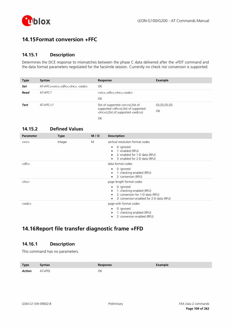
LEON-G100/G200 - AT Commands Manual
GSM.G1-SW-09002-B Preliminary FAX class 2 commands
Page 109 of 262
14.15 Format conversion +FFC
14.15.1 Description
Determines the DCE response to mismatches between the phase C data delivered after the +FDT command and the data format parameters negotiated for the facsimile session. Currently no check nor conversion is supported.
Type Syntax Response Example
Set AT+FFC=<vrc>,<dfv>,<lnc>, <wdc> OK
Read
AT+FFC? <vrc>,<dfv>,<lnc>,<wdc>
OK
Test
AT+FFC=? (list of supported <vrc>s),(list of supported <dfv>s),(list of supported <lnc>s),(list of supported <wdc>s)
OK
(0),(0),(0),(0)
OK
14.15.2 Defined Values
Parameter Type M / O Description
<vrc> Integer M vertical resolution format codes
0: ignored
1: enabled (RFU)
2: enabled for 1-D data (RFU)
3: enabled for 2-D data (RFU)
<dfc> data format codes
0: ignored
1: checking enabled (RFU)
2: conversion (RFU)
<lnc>
page length format codes
0: ignored
1: checking enabled (RFU)
2: conversion for 1-D data (RFU)
3: conversion enabled for 2-D data (RFU)
<wdc>
page with format codes
0: ignored
1: checking enabled (RFU)
2: conversion enabled (RFU)
14.16 Report file transfer diagnostic frame +FFD
14.16.1 Description
This command has no parameters.
Type Syntax Response Example
Action AT+FFD OK

LEON-G100/G200 - AT Commands Manual
GSM.G1-SW-09002-B Preliminary FAX class 2 commands
Page 110 of 262
14.17 Call termination status +FHS
14.17.1 Description
indicates the cause of a hang-up; the cause is set by the DCE at the conclusion of a FAX session and reset to 0 at the beginning of phase A.
Type Syntax Response Example
Read AT+FHS? <value>
OK
14.17.2 Defined Values
Parameter Type M / O Description
<value> Hexadecimal M 0x00: undefined
0x02: fax call cleared by the remote modem or the DTE
0x 11: Fax modem timed out in phase B
0x20: Unspecified transmitting phase B error
0x23: Invalid command received in transmitting phase B
0x40: Unspecified transmitting phase C error
0x43: Send fax data underflow
0x70: Unspecified receiving phase B error
0x50: Unspecified transmitting phase D error
0xA0: Unspecified receiving phase D error
14.18 Procedure interrupt enable +FIE
14.18.1 Description
Controls the procedure of interrupt handling.
Type Syntax Response Example
Set AT+FIE=<value> OK
Read
AT+FIE? <value>
OK
Test
AT+FIE=? (range of <value>s)
OK
(0-1)
OK
IRC +FET:<pmc>

LEON-G100/G200 - AT Commands Manual
GSM.G1-SW-09002-B Preliminary FAX class 2 commands
Page 111 of 262
14.18.2 Defined Values
Parameter Type M / O Description
<value> Integer M 0: procedure interrupt requests from the remote station are ignored and not reported to DTE
1: procedure interrupt requests from the remote station are reported to DTE (allowed only on alternate speech/fax calls) as intermediate result code +FET
<pmc>
Integer M post message command
0: MultiPage Signal - to indicate the end of a complete page of facsimile information and the return to phase C upon receipt of a confirmation
1: End Of Message - to indicate the end of a complete page of facsimile information and return to phase B
2: End Of Procedure - to indicate the end of a complete page of facsimile information and proceeding to phase E upon receipt of a confirmation
3: same as 0, with return to phase B if operator intervention is accomplished
4: same as 1, with return to phase B if operator intervention is accomplished
5: same as 2, with return to phase B if operator intervention is accomplished
14.19 Initialize facsimile parameters +FIP
14.19.1 Description
Causes the DCE to initialize all Service Class Facsimile Parameters to the manufacturer determined default settings. It does not change the +FCLASS setting. It should not be used when FAX connections are active.
Type Syntax Response Example
Set AT+FIP[=<value>] OK
Read AT+FIP? 0
OK
Test AT+FIP=? (list of supported <value>s)
OK
(0)
OK
14.19.2 Defined Values
Parameter Type M / O Description
<value> Integer M indicates the profile; only one profile is possible for <value>=0
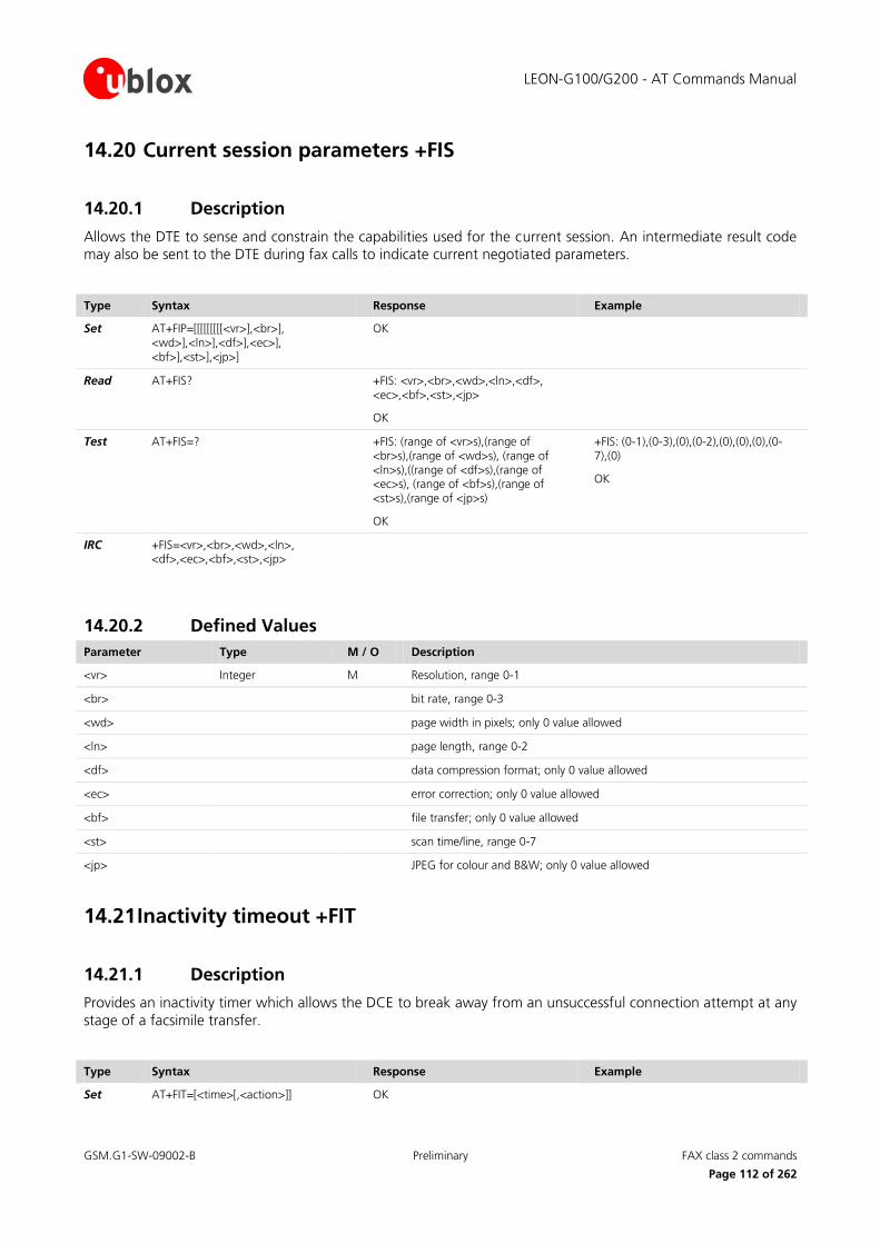
LEON-G100/G200 - AT Commands Manual
GSM.G1-SW-09002-B Preliminary FAX class 2 commands
Page 112 of 262
14.20 Current session parameters +FIS
14.20.1 Description
Allows the DTE to sense and constrain the capabilities used for the current session. An intermediate result code may also be sent to the DTE during fax calls to indicate current negotiated parameters.
Type Syntax Response Example
Set AT+FIP=[[[[[[[[[<vr>],<br>], <wd>],<ln>],<df>],<ec>], <bf>],<st>],<jp>]
OK
Read
AT+FIS? +FIS: <vr>,<br>,<wd>,<ln>,<df>, <ec>,<bf>,<st>,<jp>
OK
Test
AT+FIS=? +FIS: (range of <vr>s),(range of <br>s),(range of <wd>s), (range of <ln>s),((range of <df>s),(range of <ec>s), (range of <bf>s),(range of <st>s),(range of <jp>s)
OK
+FIS: (0-1),(0-3),(0),(0-2),(0),(0),(0),(0-7),(0)
OK
IRC +FIS=<vr>,<br>,<wd>,<ln>, <df>,<ec>,<bf>,<st>,<jp>
14.20.2 Defined Values
Parameter Type M / O Description
<vr> Integer M Resolution, range 0-1
<br> bit rate, range 0-3
<wd> page width in pixels; only 0 value allowed
<ln> page length, range 0-2
<df> data compression format; only 0 value allowed
<ec> error correction; only 0 value allowed
<bf> file transfer; only 0 value allowed
<st> scan time/line, range 0-7
<jp> JPEG for colour and B&W; only 0 value allowed
14.21 Inactivity timeout +FIT
14.21.1 Description
Provides an inactivity timer which allows the DCE to break away from an unsuccessful connection attempt at any
stage of a facsimile transfer.
Type Syntax Response Example
Set AT+FIT=[<time>[,<action>]] OK
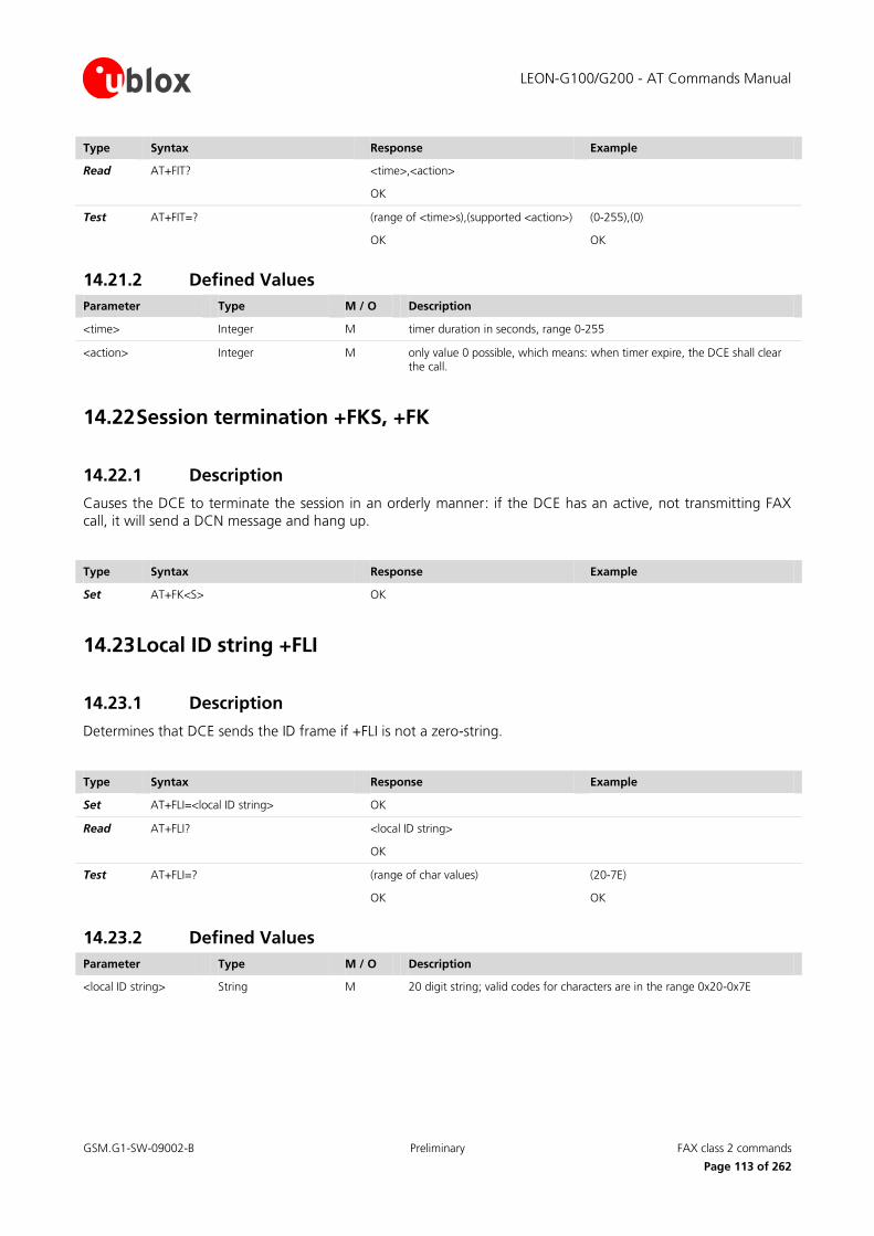
LEON-G100/G200 - AT Commands Manual
GSM.G1-SW-09002-B Preliminary FAX class 2 commands
Page 113 of 262
Type Syntax Response Example
Read AT+FIT? <time>,<action>
OK
Test AT+FIT=? (range of <time>s),(supported <action>)
OK
(0-255),(0)
OK
14.21.2 Defined Values
Parameter Type M / O Description
<time> Integer M timer duration in seconds, range 0-255
<action> Integer M only value 0 possible, which means: when timer expire, the DCE shall clear the call.
14.22 Session termination +FKS, +FK
14.22.1 Description
Causes the DCE to terminate the session in an orderly manner: if the DCE has an active, not transmitting FAX
call, it will send a DCN message and hang up.
Type Syntax Response Example
Set AT+FK<S> OK
14.23 Local ID string +FLI
14.23.1 Description
Determines that DCE sends the ID frame if +FLI is not a zero-string.
Type Syntax Response Example
Set AT+FLI=<local ID string> OK
Read AT+FLI? <local ID string>
OK
Test AT+FLI=? (range of char values)
OK
(20-7E)
OK
14.23.2 Defined Values
Parameter Type M / O Description
<local ID string> String M 20 digit string; valid codes for characters are in the range 0x20-0x7E

LEON-G100/G200 - AT Commands Manual
GSM.G1-SW-09002-B Preliminary FAX class 2 commands
Page 114 of 262
14.24 Set flow control +FLO
14.24.1 Description
Allows setting the flow control for communication via V.24 interface.
Type Syntax Response Example
Set AT+FLO=<value> OK
Read AT+FLO? <value>
OK
Test AT+FLO=? (range of <value>s)
OK
(0-2)
OK
14.24.2 Defined Values
Parameter Type M / O Description
<value>
Integer M indicates the kind of flow control
0: DTE-DCE flow control is disabled
1: DTE-DCE flow control is DC1/DC3 (SW flow control)
2: DTE-DCE flow control is RTC/CTS (HW flow control)
14.25 Indicate document to poll +FLP
14.25.1 Description
Indicates that a document is available for retrieval. By default the DTE has no document to poll.
Type Syntax Response Example
Set AT+FLP=<value> OK
Read AT+FLP? <value>
OK
Test AT+FLP=? (range of <value>s)
OK
(0)
OK
14.25.2 Defined Values
Parameter Type M / O Description
<value> Integer M only value 0 is allowed
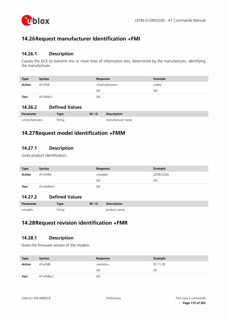
LEON-G100/G200 - AT Commands Manual
GSM.G1-SW-09002-B Preliminary FAX class 2 commands
Page 115 of 262
14.26 Request manufacturer Identification +FMI
14.26.1 Description
Causes the DCE to transmit one or more lines of information text, determined by the manufacturer, identifying the manufacturer.
Type Syntax Response Example
Action AT+FMI <manufacturer>
OK
u-blox
OK
Test AT+FMI=? OK
14.26.2 Defined Values
Parameter Type M / O Description
<manufacturer> String manufacturer name
14.27 Request model identification +FMM
14.27.1 Description
Gives product identification.
Type Syntax Response Example
Action AT+FMM <model>
OK
LEON-G200
OK
Test AT+FMM=? OK
14.27.2 Defined Values
Parameter Type M / O Description
<model> String product name
14.28 Request revision identification +FMR
14.28.1 Description
Gives the firmware version of the modem.
Type Syntax Response Example
Action AT+FMR <version>
OK
07.11.00
OK
Test AT+FMR=? OK

LEON-G100/G200 - AT Commands Manual
GSM.G1-SW-09002-B Preliminary FAX class 2 commands
Page 116 of 262
14.28.2 Defined Values
Parameter Type M / O Description
<version> String Firmware version
14.29 Minimum phase C speed +FMS
14.29.1 Description
Limits the lowest negotiable speed for a fax session. If the parameter is left blank, the default value is set.
Type Syntax Response Example
Set AT+FMS=<value> OK
Read AT+FMS? <value>
OK
Test AT+FMS=? (range of <value>s)
OK
(0-3)
OK
14.29.2 Defined Values
Parameter Type M / O Description
<value> Integer O 0: 2400 bps (default)
1: 4800 bps
2: 7200 bps
3: 9600 bps
14.30 Negotiation reporting +FNR
14.30.1 Description
Controls the reporting of messages generated during T.30 phase B negotiations.
Type Syntax Response Example
Set AT+FNR=[<rpr>[,<tpr>[,<idr>[,<nsr>]]]] OK
Read
AT+FNR? <rpr>,<tpr>,<idr>,<nsr>
OK
Test
AT+FNR=? (range of <rpr>s), (range of <tpr>),(range of <idr>s), (range of <nsr>s)
OK
(0-1),(0-1),(0-1),(0-1)
OK

LEON-G100/G200 - AT Commands Manual
GSM.G1-SW-09002-B Preliminary FAX class 2 commands
Page 117 of 262
14.30.2 Defined Values
Parameter Type M / O Description
<rpr> Integer receiver parameters reporting: 0-1 (no-yes)
<tpr> Integer transmitter parameters reporting: 0-1 (no-yes)
<idr> String ID strings reporting: 0-1 (no-yes)
<nsr> String Non-standard frame FIF octet string +FNS
14.31 Non-standard frame FIF octet string +FNS
14.31.1 Description
Allows configuring the corresponding non-standard facilities frame. Command currently not used.
Type Syntax Response Example
Set AT+FNS=<string> OK
Read AT+FNS? <string>
OK
Test AT+FNS=? (range of character codes)
OK
(20-7E)
OK
14.31.2 Defined Values
Parameter Type M / O Description
<string> String string of characters in the range 0x20-0x7E
14.32 NSF message data indication +FND
14.32.1 Description
Controls indication of non-standard facilities frames. Command currently not used.
Type Syntax Response Example
Set AT+FND=<value> OK
Read AT+FND? <value>
OK
Test AT+FND=? (range of <value>s)
OK
(0-1)
OK
14.32.2 Defined Values
Parameter Type M / O Description
<value> Integer range 0-1 (enabled/disabled).

LEON-G100/G200 - AT Commands Manual
GSM.G1-SW-09002-B Preliminary FAX class 2 commands
Page 118 of 262
14.33 Selective polling address +FPA
14.33.1 Description
Sets the selective polling address. The DCE should send the numeric string contained in the +FPA at the times specified in T.30, if the corresponding parameter is not zero string. Command currently not used.
Type Syntax Response Example
Set AT+FPA=<selective polling address string>
OK AT+FPA=1234
OK
Read AT+FPA? <selective polling address string>
OK
“1234"
OK
Test AT+FPA=? (range of character codes)
OK
(20-7E)
OK
14.33.2 Defined Values.
Parameter Type M / O Description
<selective polling address string>
String M 20 digit string: values are in range 0x20-0x7E
14.34 Local polling ID string +FLI
14.34.1 Description
Allows the DCE to send the ID frame if +FPI is not a null string. Command currently not used.
Type Syntax Response Example
Set AT+FLI=<local polling ID string> OK
Read AT+FLI? <local polling ID string>
OK
“1234"
OK
Test AT+FLI=? (range of character codes)
OK
(20-7E)
OK
14.34.2 Defined Values
Parameter Type M / O Description
<local polling ID string>
String M only null string “” is allowed
LEON-G100/G200 - AT Commands Manual
GSM.G1-SW-09002-B Preliminary FAX class 2 commands
Page 119 of 262
14.35 Packet protocol control +FPP
14.35.1 Description
Allows controlling the packet protocol. Packet protocol is currently not supported.
Type Syntax Response Example
Set AT+FPP=[<value>] OK
Read AT+FPP? <value>
OK
Test AT+FPP=? (supported <value>)
OK
(0)
OK
14.35.2 Defined Values
Parameter Type M / O Description
<value> Integer only value 0 allowed
14.36 Page status +FPS
14.36.1 Description
Sets the post page response, in particular end-of-page status, to be sent to the remote part. During fax
transmission, post page response of the remote part is indicated to the DTE with an intermediate result code +FPS.
Type Syntax Response Example
Set AT+FPS=[<value>] OK
Read AT+FPS? <value>
OK
Test AT+FPS=? (range of <value>)
OK
(1-5)
OK
14.36.2 Defined Values
Parameter Type M / O Description
<value> Integer M 1: MCF, page good (default value)
2: RTN, page bad; retrain requested
3: RTP, page good; retrain requested
4: PIN, page bad; interrupt requested
5: PIP, page good; interrupt requested

LEON-G100/G200 - AT Commands Manual
GSM.G1-SW-09002-B Preliminary FAX class 2 commands
Page 120 of 262
14.37 Password parameter +FPW
14.37.1 Description
Sets the password. The DCE sends the numeric string contained in +FPW at the times specified in T.30, if the corresponding parameter is not a null string.
Type Syntax Response Example
Set AT+FPW=<password string> OK AT+FPW=1234
OK
Read AT+FPW? “<password string>”
OK
Test AT+FPW=? (range of <value>)
OK
“1234"
OK
14.37.2 Defined Values
Parameter Type M / O Description
<password string> String M valid characters: 0-9, *, #, space
14.38 Receive quality thresholds +FRQ
14.38.1 Description
Allows making the “Copy Quality OK” decision using the command parameters. Command currently not used.
Type Syntax Response Example
Set AT+FRQ=<pgl>,<cbl> OK
Read AT+FRQ? <pgl>,<cbl>
OK
Test AT+FPW=? (supported <pgl>),(supported <cbl>)
OK
(0),(0)
OK
14.38.2 Defined Values
Parameter Type M / O Description
<pgl> Integer M percentage of good lines: only value 0 accepted
<cbl> Integer M consecutive bad lines: only value 0 accepted
LEON-G100/G200 - AT Commands Manual
GSM.G1-SW-09002-B Preliminary FAX class 2 commands
Page 121 of 262
14.39 Error correction mode retry count +FRY
14.39.1 Description
Controls the retry counter in Error Correcting Mode. Command currently not used.
Type Syntax Response Example
Set AT+FRY=[<value>] OK
Read AT+FRY? <count>
OK
Test AT+FPY=? (range of <count>)
OK
(0-FF)
OK
14.39.2 Defined Values
Parameter Type M / O Description
<value> Integer O in range 0-0xFF (0 if blank)
14.40 SubAddress parameter +FSA
14.40.1 Description
Sets the subaddress. The DCE sends the numeric string configured via AT+FSA at the times specified in T.30, if
the corresponding parameter is not a null string.
Type Syntax Response Example
Set AT+FSA=<destination SubAddress string>
OK AT+FSA=1234
OK
Read AT+FSA? “<destination SubAddress string >”
OK
“1234"
OK
Test AT+FSA=? (range of character codes)
OK
(20-7E)
OK
14.40.2 Defined Values
Parameter Type M / O Description
<destination SubAddress string>
String M 20 digit string; allowed values: 0-9, *, #, space
14.41 Request to poll +FSP
14.41.1 Description
This command indicates whether or not the DTE wants to poll. Command currently has not used.

LEON-G100/G200 - AT Commands Manual
GSM.G1-SW-09002-B Preliminary FAX class 2 commands
Page 122 of 262
Type Syntax Response Example
Set AT+FSP=[<value>] OK
Read AT+FSP? <value>
OK
Test AT+FSP=? (supported < value >)
OK
(0)
OK
14.42 Fax intermediate result codes
14.42.1 Description
According to Recommendation T.32, Tab. 6, the following intermediate result codes are provided to the DTE
during fax calls.
IRC Meaning
+FCO Indicates connection with a fax terminal
+FVO Indicates transition to voice
+FHS Call terminated with status
+FCS Report the DCS frame information
+FDCS Report the DCS frame information for speech/fax alternate calls
+FIS Report the DIS frame information
+FTI Report the remote (transmitting) ID, from TSI (Transmitting Subscriber Identification) frame
+FTSI Report the remote (transmitting) ID, from TSI (Transmitting Subscriber Identification) frame for speech/fax alternate calls
+FCI Report the remote (called) ID, from CSI (Called Subscriber Identification
+FCSI Report the remote (called) ID, from CSI (Called Subscriber Identification for speech/fax alternate calls
+FET Report post page message
+FPS Report received page status
+FPTS Report received page status for speech/fax alternate calls
+FHT Report transmitted HDLC frames
+FHR Debug report received HDLC frames
LEON-G100/G200 - AT Commands Manual
GSM.G1-SW-09002-B Preliminary V24 control and V25ter commands
Page 123 of 262
15 V24 control and V25ter commands
15.1 Reset to default configuration Z
15.1.1 Description
Resets the parameters of all AT-commands. The values related to parameters contained in a user profile will be
taken from the corresponding NVRAM-profile, indicated by the <value>.
Type Syntax Response Example
Action ATZ<value> OK
15.1.2 Defined Values
Parameter Type M / O Description
<value> Integer M indicates NVRAM profile; possible values 0-1
15.2 Set to factory defined configuration &F
15.2.1 Description
Resets only the parameters of the not FAX-related AT-commands to factory defined defaults.
Type Syntax Response Example
Action AT&F[<value>] OK
15.2.2 Defined
Parameter Type M / O Description
<value> Integer M Only 0 allowed
15.3 Circuit 109 behavior &C
15.3.1 Description
Determines the state of circuit 109 relates to the detection of received line signal from the remote end.
Type Syntax Response Example
Action AT&C[<value>] OK

LEON-G100/G200 - AT Commands Manual
GSM.G1-SW-09002-B Preliminary V24 control and V25ter commands
Page 124 of 262
15.3.2 Defined Values
Parameter Type M / O Description
<value> Integer M Indicates the behaviour of circuit 109
0: DCE always presents ON condition on circuit 109
1: circuit 109 changes in accordance with the underlying DCE, which may include functions other than the physical layer functions (default value)
15.4 Circuit 108/2 behaviour &D
15.4.1 Description
Determines how DCE responds when circuit 108/2 is changed from ON to OFF condition during on-line data state.
Type Syntax Response Example
Action AT&D[<value>] OK
15.4.2 Defined Values
Parameter Type M / O Description
<value> Integer M 0: the DCE ignores circuit 108/2
1: upon an ON-to-OFF transition of circuit 108/2, the DCE enters online command state and issues an OK result code (default value)
2: upon an ON-to-OFF transition of circuit 108/2, the DCE instructs the underlying DCE to perform an orderly cleardown of the call. Automatic answer is disabled while circuit 108/2 remains OFF
15.4.3 ~+++ behaviour in GPRS &D
A special meaning of the &D value is provided for the ~+++ sequence during a GPRS data transfer (this is outside the V25-ter specification scope). The ~+++ causes context deactivation during a GPRS data transfer
session for the AT&D0, AT&D1 values (note that the +++ return to on-line command mode is provided for
each &D value during a CSD data call [20]).
A different implementation for the ~+++ is done with the &D2 value: GPRS data transfer is escaped and
system returns in the on-line command state. ATO command is used to resume the GPRS data transfer
session.
During the on-line command mode different AT commands can be sent but some limitations are present:
o Data calls in GPRS on-line command mode cannot be granted (activate the AT+CRC=1 mode in order to identify the kind of call and reject data incoming calls if GPRS is in the on-line command mode);
o MUX functionalities cannot be used in cooperation with the GPRS on-line command mode.

LEON-G100/G200 - AT Commands Manual
GSM.G1-SW-09002-B Preliminary V24 control and V25ter commands
Page 125 of 262
15.4.4 Circuit 108/2, +++ behaviour for the different &D: summarizing table
CSD GPRS
+++ DTR On to Off in data state ~+++
DTR On to Off in data state
&D0 Command mode Data state Context deactivation Context deactivation
&D1 Command mode Command mode Context deactivation Context deactivation
&D2 Command mode Cleardown call Command mode (with
limitations) Context deactivation
15.5 DSR override &S
15.5.1 Description
Selects how the modem will control DSR (V.24 control line 107).
Type Syntax Response Example
Action AT&S[<value>] OK
15.5.2 Defined Values
Parameter Type M / O Description
<value> Integer M 0: sets the DSR line to ON (default value)
1: sets the DSR line to OFF
15.6 Flow control &K
15.6.1 Description
Controls the flow control mechanism.
Type Syntax Response Example
Action AT&K[<value>] OK

LEON-G100/G200 - AT Commands Manual
GSM.G1-SW-09002-B Preliminary V24 control and V25ter commands
Page 126 of 262
15.6.2 Defined Values
Parameter Type M / O Description
<value> Integer M 0: disable DTE flow control
3: enable RTS/CTS DTE flow control (default value)
4: enable XON/XOFF DTE flow control
5: enable XON/XOFF DTE flow control
6: enable XON/XOFF DTE flow control
15.7 Store current configuration &W
15.7.1 Description
Stores the current active configuration into one of the two user profiles in NVRAM as denoted by the parameter value. The profile is stored for the terminal where the storing is requested.
Profile parameter storage is executed as a background task which can not be controlled. In specific cases, it can
happen that some parameters are not saved prior to a power loss.
Type Syntax Response Example
Action AT&W[<value>] OK
15.7.2 Defined Values
Parameter Type M / O Description
<value> Integer M 0: selects profile 0 (default value)
1: selects profile 1
15.8 Display current configuration &V
15.8.1 Description
Reports the current configuration and the stored user profiles.
Not all command parameters are listed with this command. For the complete list of the parameters stored
in the profile please refer to Appendix B.1

LEON-G100/G200 - AT Commands Manual
GSM.G1-SW-09002-B Preliminary V24 control and V25ter commands
Page 127 of 262
Type Syntax Response Example
Action AT&V[<value>] ACTIVE PROFILE:
List of commands stored in the active profile with the related values
STORED PROFILE 0:
List of commands stored in the profile 0 with the related values
STORED PROFILE 1:
List of commands stored in the profile 1 with the related values
OK
ACTIVE PROFILE:
&C1, &D1, &K3, E1, Q0, V1, X4, S00:000, S02:043, S03:013, S04:010, S05:008, S07:060, +CBST:007, 000, 001, +CRLP:061, 061, 048, 006, +CR:000, +CRC:000, +IPR: 0, +COPS:0, FFFFF, +ICF:3,1, +UPSV: 1,2000
STORED PROFILE 0:
&C1, &D1, &K3, E1, Q0, V1, X4, S00:000, S02:043, S03:013, S04:010, S05:008, S07:060, +CBST:007, 000, 001, +CRLP:061, 061, 048, 006, +CR:000, +CRC:000, +IPR: 0, +COPS:0, FFFFF, +ICF:3,1, +UPSV: 1,2000
STORED PROFILE 1:
&C1, &D1, &K3, E1, Q0, V1, X4, S00:000, S02:043, S03:013, S04:010, S05:008, S07:060, +CBST:007, 000, 001, +CRLP:061, 061, 048, 006, +CR:000, +CRC:000, +IPR: 0, +COPS:0, FFFFF, +ICF:3,1, +UPSV: 1,2000
OK
15.9 Designate a default reset profile &Y
15.9.1 Description
Selects which user profile will be used after a hardware reset. Settings are described in the chapter related to the &V command. An error is returned if <value> is greater then 2, or NVRAM is not installed or is not operational.
Type Syntax Response Example
Action AT&Y[<value>] OK
15.9.2 Defined Values
Parameter Type M / O Description
<value> Integer M 0: selects profile 0
1: selects profile 1
2: selects the default factory settings

LEON-G100/G200 - AT Commands Manual
GSM.G1-SW-09002-B Preliminary V24 control and V25ter commands
Page 128 of 262
15.10 Request identification information I
15.10.1 Description
Causes the DCE to transmit one or more lines of information text, determined by the manufacturer, followed by a final result code.
Type Syntax Response Example
Action AT&I[<value>] <string>
OK
15.10.2 Defined Values
Parameter Type M / O Description
<value> Integer M in the range 0-9; for each value a text provided by the manufacturer will be displayed
0: provide the product type number of the module
1-9: undefined
15.11 Request manufacturer Identification +GMI
15.11.1 Description
Causes the DCE to transmit information text, determined by the manufacturer, identifying the manufacturer.
Type Syntax Response Example
Action AT+GMI <manufacturer>
OK
15.11.2 Defined Values
Parameter Type M / O Description
<manufacturer> String
15.12 Request model identification +GMM
15.12.1 Description
Returns the model identification.
Type Syntax Response Example
Action AT+GMM <model>
OK
LEON-G100/G200 - AT Commands Manual
GSM.G1-SW-09002-B Preliminary V24 control and V25ter commands
Page 129 of 262
15.12.2 Defined Values
Parameter Type M / O Description
<model> String
15.13 Request revision identification +GMR
15.13.1 Description
Returns the firmware version of the mobile station.
Type Syntax Response Example
Action AT+GMR <version>
OK
15.13.2 Defined Values
Parameter Type M / O Description
<version> String
15.14 Request product serial number identification +GSN
15.14.1 Description
Returns the IMEI (International Mobile Equipment Identity) of the MT.
Type Syntax Response Example
Action AT+GSN <IMEI>
OK
15.14.2 Defined Values
Parameter Type M / O Description
<IMEI> String
15.15 DTE-DCE character framing +ICF
15.15.1 Description
Sets the local serial port start-stop (asynchronous) character framing which is used in information interchange
between DCE and DTE. Only 8 bit frames are supported, with and without parity. Value 0 corresponds to the auto-detect case.

LEON-G100/G200 - AT Commands Manual
GSM.G1-SW-09002-B Preliminary V24 control and V25ter commands
Page 130 of 262
Due to hardware characteristics the frame recognition can be present in conjunction with the autobauding recognition only i.e. the AT+ICF command is effective if AT+IPR is set to 0 only. In this case the AT+ICF
returns the 0 value
Outside the autobauding conditions the AT+ICF=0 answers OK but it does not switch the system to the
automatic frame recognition and it doesn’t take actions. In this scenario the AT+ICF? Command will return
the current value of the frame format. The AT+IPR=0 command instead forces the AT+ICF to be 0
Under the autobauding conditions, the AT+ICF command provided with a value different than 0 will
answer ERROR since it is not possible to specify a frame type in those autodetect conditions
Under the autobauding conditions, the AT+ICF command provided with a value different than 0 will answer ERROR since it is not possible to specify a frame type in those autodetect conditions
If a data frame format refers to a frame without parity (ex. Format 3), the parity value returned by the AT+ICF? command has no meaning
The stop bit number cannot be automatically recognized i.e. if the system is switched from the 8N2 to the
autodetect feature and a 1 stop bit frame is provided at the serial port, unpredictable behaviour of the system can occurs
Type Syntax Response Example
Set AT+ICF=[<format>[,<parity>]] OK AT+ICF=3,1
OK
Read AT+ICF? +ICF: <format>,<parity>
OK
AT+ICF?
+ICF: 3,1
Test AT+ICF=? +ICF: (list of supported <format>s),(list of supported <parity>s)
OK
+ICF: (0-3,5),(0-1)
OK
15.15.2 Defined Values
Parameter Type M / O Description
<format>
Integer M 0: auto detect
1: 8 data 2 stop
2: 8 data 1 parity 1 stop
3: 8 data 1 stop
<parity> Integer M 0: odd
1: even
15.16 DTE-DCE local flow control +IFC
15.16.1 Description
Controls the operation of local flow control between DTE and DCE used when data are sent or received.
Type Syntax Response Example
Set AT+IFC=[<DCE_by_DTE> [,<DTE_by_DCE>]]
OK AT+IFC=2,2
OK

LEON-G100/G200 - AT Commands Manual
GSM.G1-SW-09002-B Preliminary V24 control and V25ter commands
Page 131 of 262
Type Syntax Response Example
Read AT+IFC? +IFC: <DCE_by_DTE>, <DTE_by_DCE>
OK
AT+IFC?
+IFC: 2,2
OK
Test AT+IFC=? +IFC: (list of supported <DCE_by_DTE>),(list of supported <DTE_by_DCE>s)
OK
+IFC: (0-2),(0-2)
OK
15.16.2 Defined Values
Parameter Type M / O Description
<DCE_by_DTE>
Integer M 0: none
1: DC1/DC3 on circuit 104 (XON/XOFF)
2: circuit 106 (CTS)
<DTE_by_DCE>
Integer M 0: none
1: DC1/DC3 on circuit 103 (XON/XOFF)
2: circuit 105 (RTS)
<DCE_by_DTE> and <DTE_by_DCE> must be provided with same value in pairs (i.e 0,0 1,1 and 2,2 are allowed but 0,1 or 2,0 are not allowed).
15.17 Set flow control \Q
15.17.1 Description
Controls the operation of local flow control between DTE and DCE. Used when data are sent or received.
Type Syntax Response Example
Set AT\Q[<value>] OK AT\Q3
OK
15.17.2 Defined Values
Parameter Type M / O Description
<value>
Integer M 0: no flow control
1: DC1/DC3 on circuit 103 and 104 (XON/XOFF)
2: DTE_by_DCE on circuit 105 (RTS)
3: DCE_by_DTE on circuit 106 (CTS and DTE_by_DCE on circuit 105 (RTS)
15.18 Fixed DTE rate +IPR
15.18.1 Description
Specifies the data rate at which the DCE will accept commands. The full range of data rates depends on HW or other criteria. Data rate 0 means autobauding, i.e the baud rate is recognized by the system in the Offline
Command State only when the “at” or “AT” sequence is provided.

LEON-G100/G200 - AT Commands Manual
GSM.G1-SW-09002-B Preliminary V24 control and V25ter commands
Page 132 of 262
Note:
System can start in autobading (necessary to program the NVM with the baudrate parameter set to 0) or the
autobauding can be enabled with the AT+IPR=0 command if the NVM is programmed for the fixed rate 115200 bps
Autobauding values which can be discovered are the same of the fixing case i.e. 2400, 4800, 9600, 19200,
38400, 57600, 115200 bps. Although values outside this set will be detected (for ex. 1200 bps or 230400 bps), AT commands provided with a baudrate other than values declared, leads to unpredictable results
If the system starts in autobading (i.e. the IPR is 0) the first at sequence provided to the module will detect
the baudrate. For example the first command sent from the DTE at any rate can be: AT+CPIN=”1234”
Characters different than AT are ignored during the baud rate detection since the hardware detection
sequence is triggered on the “at” or “AT” sequence. “At” or “aT” sequences are invalid too, both of the
detection chars have to be small or capital
Only UART0 supports autobauding
Power saving is exited at the “A” (or “a”) char of the autobauding sequence (if the flow control is
hardware) and a full recognition needs to be determined before entering in the power save state again (when the power saving timeout is elapsed). If the power saving is exited and the autobauding sequence is
not provided i.e. the “A” char is the only char provided, the module stays out of the power saving
indefinitely
Autobauding result can be unpredictable with spurious chars if the power saving is entered and the flow
control is disabled. If the hardware flow control is present, the DTE can be synchronized with the power saving cycle through the module CTS line i.e. the delivery of the “AT” sequence during the module awake
can be granted by the DTE and the power saving can be exited in the proper way. It is recommended to
disable the power saving if no hardware flow control is used
Data rate 0 affects the AT+ICF command too which value is automatically switched to the 0 value. Read
carefully the description of the AT+ICF command for further limitations.
Type Syntax Response Example
Set AT+IPR=[<rate>] OK AT+IPR=9600
OK
Read AT+IPR? +IPR: <rate>
OK
+IPR: 9600
OK
Test AT+IPR=? +IPR: (list of supported autodetectable <rate> values)[,(list of fixed only <rate> values)]
OK
+IPR: (0, 2400,4800,9600,19200,38400,57600,115200),()
OK
15.18.2 Defined Values
Parameter Type M / O Description
<rate>
Integer M Buad rate
0: autobauding
2400, 4800, 9600, 19200, 38400, 57600, 115200
1200 and 230400 bps are possible only in autobauding
LEON-G100/G200 - AT Commands Manual
GSM.G1-SW-09002-B Preliminary V24 control and V25ter commands
Page 133 of 262
15.19 System can Return to on-line data state O
15.19.1 Description
Causes the DCE to return to online data state and issue a CONNECT or CONNECT <text> result code on DTE.
Type Syntax Response Example
Action MT is in state data transfer +++
(return to online command mode) MT is in online command mode ATO
OK
15.20 Escape character S2
15.20.1 Description
Controls the decimal value of the ASCII character used as the escape character. A value over 127 disables the
escape process, i.e. no escape character will be recognized. The escape sequence contains three escape characters e.g. “+++”.
Type Syntax Response Example
Set ATS2=<value> OK ATS2=43
OK
Read ATS2? <value>
OK
043
OK
15.20.2 Defined Values
Parameter Type M / O Description
<value> Integer M range 1 to 255. Answer to Read command is in “xxx” format. Default value: 043 (ASCII ‘+’).
15.21 Command line termination character S3
15.21.1 Description
Sets a value representing the decimal IRA5 value of the character recognized by the DCE from the DTE, to terminate the incoming command line. It is also generated by the DCE as part of the header, trailer and
terminator for result codes and information text, along with the S4 setting.
Type Syntax Response Example
Set ATS3=<value> OK ATS3=13
OK
Read ATS3? <value>
OK
013
OK

LEON-G100/G200 - AT Commands Manual
GSM.G1-SW-09002-B Preliminary V24 control and V25ter commands
Page 134 of 262
15.21.2 Defined Values
Parameter Type M / O Description
<value> Integer M range 0 to 127. Answer to Read command is in “xxx” format. Default value: 013 (ASCII carriage return (CR, IRA5 0/13)).
15.22 Response formatting character S4
15.22.1 Description
Sets a value representing the decimal IRA5 value of the character generated by the DCE as part of the header, trailer and terminator for result codes and information text, along with the S3 setting.
Type Syntax Response Example
Set ATS4=<value> OK ATS4=10
OK
Read ATS4? <value>
OK
010
OK
15.22.2 Defined Values
Parameter Type M / O Description
<value> Integer M range 0 to 127. Answer to Read command is in “xxx” format. Default is 10 (line feed (LF, IRA5 0/10))
15.23 Command line editing character S5
15.23.1 Description
Sets a value representing the decimal IRA5 character recognized by the DCE as a request to delete from the
command line the immediately preceding character.
Type Syntax Response Example
Set ATS5=<value> OK ATS5=8
OK
Read ATS5? <value>
OK
008
OK
15.23.2 Defined Values
Parameter Type M / O Description
<value> Integer M range 0 to 127. Answer to Read command is in “xxx” format. Default value: 8 (ASCII backspace (BS, IRA5 0/8))

LEON-G100/G200 - AT Commands Manual
GSM.G1-SW-09002-B Preliminary V24 control and V25ter commands
Page 135 of 262
15.24 Pause before blind dialling S6
15.24.1 Description
Specifies the time in seconds, that the DCE waits between connecting to the line and dialling, when dial tone is not implemented or enabled. The command is not applicable for signal based mobile phone software.
Type Syntax Response Example
Set ATS6=<value> OK ATS6=2
OK
Read ATS6? <value>
OK
002
OK
15.24.2 Defined Values
Parameter Type M / O Description
<value> Integer M range 2 to 10. Answer to Read command is in “xxx” format. Default 2 seconds
15.25 Connection completion timeout S7
15.25.1 Description
Specifies time in seconds, that the DCE shall allow between either answering a call or completion of dialling and
establishment of a connection with a remote site.
Type Syntax Response Example
Set ATS7=<value> OK ATS7=30
OK
Read ATS7? <value>
OK
030
OK
15.25.2 Defined Values
Parameter Type M / O Description
<value> Integer M range 1 to 255. Answer to Read command is in “xxx” format. Default: 60 seconds

LEON-G100/G200 - AT Commands Manual
GSM.G1-SW-09002-B Preliminary V24 control and V25ter commands
Page 136 of 262
15.26 Command dial modifier time S8
15.26.1 Description
Specifies time in seconds, that the DCE shall pause, during dialling, when a “,” dial modifier is encountered in a dial string. The command has no effect.
Type Syntax Response Example
Set ATS8=<value> OK ATS8=4
OK
Read ATS8? <value>
OK
004
OK
15.26.2 Defined Values
Parameter Type M / O Description
<value> Integer M range 1 to 255. Answer to Read command is in “xxx” format. Default: 2
15.27 Automatic disconnect delay S10
15.27.1 Description
Specifies time in tenth of a second, that the DCE will remain connected to the line after the DCE has indicated the absence of received line signal. Not supported for GSM but OK returned.
15.28 Escape prompt delay (EPD) S12
15.28.1 Description
Defines the maximum period, in fiftieths of a second, allowed between receipt of the last character of the three
escape character sequence from the DTE and sending of the OK result code to the DTE. If any characters are
detected during this time, the OK will not be sent.
Type Syntax Response Example
Set ATS12=<value> OK ATS12=80
OK
Read ATS12? <value>
OK
080
OK
15.28.2 Defined Values
Parameter Type M / O Description
<value> Integer M range 0 to 255. Answer to Read command is in “xxx” format. Default: 50 (1 second)

LEON-G100/G200 - AT Commands Manual
GSM.G1-SW-09002-B Preliminary V24 control and V25ter commands
Page 137 of 262
15.29 Command echo E
15.29.1 Description
Controls whether or not the MT echoes characters received from the DTE during command state.
Type Syntax Response Example
Set ATE[<value>] OK ATE1
OK
15.29.2 Defined Values
Parameter Type M / O Description
<value> Integer M 0: echo off
1: echo on (default value)
15.30 Result code suppression Q
15.30.1 Description
Determines if DCE transmits result codes to the DTE or not. When result codes are being suppressed, no portion
of any intermediate, final or URC is transmitted. Information text transmitted in response to commands is not affected by this setting.
Type Syntax Response Example
Set ATQ[<value>] OK ATQ1
OK
15.30.2 Defined Values
Parameter Type M / O Description
<value> Integer M 0: DCE transmits result codes (default value)
1: Result codes are suppressed and not transmitted
15.31 DCE response format V
15.31.1 Description
Control the contents of the header and trailer transmitted with result codes and information responses. It also
determines whether result codes are transmitted in a numeric form or a alphabetic (or verbose) form. The text
portion of information responses is not affected by this setting. The effect of V setting on response formats is described below:
Format for information responce:
for V0: <text><CR><LF>
for V1: <CR><LF><text><CR><LF>
LEON-G100/G200 - AT Commands Manual
GSM.G1-SW-09002-B Preliminary SIM toolkit
Page 138 of 262
Format for result codes:
for V0: <numeric code><CR>
for V1: <CR><LF><verbose code><CR><LF>
Type Syntax Response Example
Set ATV[<value>] OK ATV1
OK
15.31.2 Defined Values
Parameter Type M / O Description
<value> Integer M 0: DCE transmits limited headers, trailers, and numeric text
1: DCE transmits full headers, trailers and, verbose response text (default value)
15.32 Result code selection and call progress monitoring control X
15.32.1 Description
Determines whether or not the DCE transmits particular result codes to the DTE. It also controls whether or not
the DCE verifies the presence of dial tone when it first goes off-hook to begin dialling and whether or not engaged tone (busy signal) detection is enabled.
Type Syntax Response Example
Set ATX[<value>] OK ATX1
OK
15.32.2 Defined Values
Parameter Type M / O Description
<value> Integer M 0: CONNECT result code is given upon entering online data state; dial tone and busy detection are disabled
1: CONNECT <text> result code is given upon entering online data state; dial tone and busy detection are disabled
2: CONNECT <text> result code is given upon entering online data state; dial tone detection is enabled and busy detection is disabled
3: CONNECT <text> result code is given upon entering online data state; dial tone detection is disabled and busy detection is enabled
4: CONNECT <text> result code is given upon entering online data state; dial tone and busy detection are both enabled (default value)
16 SIM toolkit
16.1 Introduction
The commands in this section work properly only if the SIM toolkit interface has been activated by the DTE.
Otherwiese the SIM-toolkit processing will be blocked.
LEON-G100/G200 - AT Commands Manual
GSM.G1-SW-09002-B Preliminary SIM toolkit
Page 139 of 262
The activation of the SIM toolkit interface is done by AT+CFUN=6. After the activation of the SIM toolkit interface, the setup menu may be displayed via URC +STKPRO when available from the SIM (immediately or after
PIN insertion).
16.2 SIM-APPL-TK proactive commands +STKPRO
16.2.1 Description
Displays the list of supported proactive commands. Only the test command syntax is allowed.
In addition an URC +STKPRO is provided during STK transactions.
Type Syntax Response Example
Test AT+STKPRO=? +STKPRO=(list of supported <proactive_cmd>s)
OK
+STKPRO=01,05,16,17,18,19,20,21,32,33,34,35,36,37,38,40,53
OK
URC +STKPRO: 01,<type>
+STKPRO: 05,<event_list>
+STKPRO: 16,<number>,<subaddr>,<type>,<alpha_1>, <icon_id1>,<alpha_2>,<icon_id2>
+STKPRO: 17,<ss_data>,<alpha>,<icon_id>, <ref_number>
+STKPRO: 18,<dcs>,<hex_string>,<alpha>,<icon_id>, <ref_number>
+STKPRO: 19,<alpha>,<icon_id>,<ref_number>
+STKPRO. 20,<alpha>,<icon_id>,<dtmf_string>
+STKPRO: 21,<URL>,<alpha>,<icon_id>
+STKPRO: 32,<tone>,<unit>,<interval>,<alpha>, <icon_id>
+STKPRO: 33,<type>,<dcs>,<hex_string>,<icon_id>, <imm_resp>
+STKPRO: 34,<type>,<dcs>,<hex_string>,<icon_id>
+STKPRO: 35,<type>,<dcs>,<hex_string>, <max_rsp_len>,<min_rsp_len>,<default_text>,<icon_id>
+STKPRO: 36,<type>,<alpha>,<item_id>,<total_items>, <item_text>,<next_action>,<default_item>
+STKPRO: 37,<type>,<alpha>,<item_id>,<total_ite

LEON-G100/G200 - AT Commands Manual
GSM.G1-SW-09002-B Preliminary SIM toolkit
Page 140 of 262
Type Syntax Response Example
ms>, <item_text>,<next_action>
+STKPRO: 38,<type>
+STKPRO: 40,<dcs>,<hex_string>,<icon_id>
+STKPRO: 53,<language>
16.2.2 Defined Values
Parameter Type M / O Description
<alpha> String
<alpha_1> String
<alpha_2> String
<item_text> String
<default_text> String
<dcs> Integer Data coding scheme
<default_item> Integer Default item (see item_id)
<dtmf_string> String String of DTMF tones coded in BCD (same format as the Dialling number string defined for EFADN in TS 11.11)
<event list>
Integer 04: User activity event
05: Idle screen available event
07: Language selection
08: Browser Termination event
<hex_string> String
<icon_id>,
<icon_id1>,
<icon_id2>
String Icon identifier, set to 0 since no graphical interface is provided
<interval> Integer Time duration in number of units
<imm_resp> Integer Immediate response
<item_id> identifier of an item within a list
<item_text> String text string of item
<language> String 2 bytes string indicating the language
<max rsp len> Integer Maximum response length
<min rsp len> Integer Minimum response length
<next_action>
<number> Called party number
<proactive_cmd>
Integer 01: refresh
05: set up event list
16: set up call
17: send SS
18: send USSD
19: send SMS
20: send DTMF
21: launch browser
32: play tone
33: display text
34: get inkey
35: get input
36: select item
37: set up menu

LEON-G100/G200 - AT Commands Manual
GSM.G1-SW-09002-B Preliminary SIM toolkit
Page 141 of 262
38: language setting
40: set up idle mode text
53: language notification
<ref_number> Integer Reference number
<subaddr> Called party subaddr
<ss_data> String
<type> Integer command qualifier; value 4 meaning “language”
<tone>
Integer 01: dial tone
02: call subscriber busy
03: congestion
04: radio path acknowledge
05: radio path not available
06: error / special information
07: call waiting tone
08: ringing tone
10: general beep
11: positive acknowledgement tone
12: negative acknowledgement or error tone
<total_items> Integer
<unit>
Integer 0: minutes
1: seconds
2: tenth of seconds
<URL> String URL to be loaded
16.3 SIM-APPL-TK terminal response +STKTR
16.3.1 Description
Allows entering response to a SIM Toolkit proactive command which has been displayed by the URC +STKPRO.
If no response is entered, after a timeout of duration may range from 180 to 300 seconds, the modem sends an
autonomous terminal response to the SIM in order to complete the STK transaction; the result depends on the
pending proactive command and can be “Command performed successfully”, “No response from user”, “Command type not understood by ME” or “Command data not understood by ME” (see TS 51.014).
AT+STKTR command must be entered always, in order to terminate the pending STK session at the MT-DTE
interface, and to be able to enter additional STK commands.
The parameters to be entered depend on the proactive command:
+STKTR:01,<result>,[<add_result>] refresh
+STKTR:05,<result> set up event list
+STKTR:16,<result>,[<add_result>] set up call
+STKTR:17,<result>,<add_result>,[<reference_number>] send SS
+STKTR:18,<result>,<add_result>,[<reference_number>] send USSD
+STKTR:19,<result>,<add_result>,[<reference_number>] send SMS
+STKTR:20,<result>,[<add_result>] send DTMF
+STKTR:21:<result> launch browser
+STKTR:32,<result>,<add_result> play tone
+STKTR:33,<result>,<add_result> display text
+STKTR:34,<result>,<add_result>,0,<dcs>,<hex_string> get inkey
LEON-G100/G200 - AT Commands Manual
GSM.G1-SW-09002-B Preliminary SIM toolkit
Page 142 of 262
+STKTR:35,<result>,<add_result>,0,<dcs>,<hex_string> get input
+STKTR:36,<result>,<add_result>,0,<dcs>,<hex_string> select item
+STKTR:37,<result>,<add_result> set up menu
+STKTR:38,<type>,<language> language setting
+STKTR:40,<result>,<add_result> set up idle mode text
*0 stands for the obsolete parameter <last_cmd>
Type Syntax Response Example
Set
AT+STKTR=<proactive_cmd>[,<type>][,<result>,<add_result>[,<reference_number>][,<last_cmd>][,<dcs>][,<hex string>]]
OK AT+STKTR=1,0
OK
Test
AT+STKTR=? +STKTR=list of supported <result> values
OK
+STKTR=01,05,16,17,18,19,20,21,32,33,34,35,36,37,38,40,53
OK
16.3.2 Defined Values
Parameter Type M / O Description
<proactive_cmd> Integer M Decimal code indicates the command (refer +STKPRO command description - paragraph 16.2)
<result>
Integer 0: command performed successfully
1: command performed with partial comprehension
2: command performed with missing information
3: REFRESH performed with additional EFs read
4: command performed successfully, but requested icon could not be displayed
5: command performed but modified by call control by SIM
6: command performed successfully, limited service
7: command performed with modification
16: proactive SIM session terminated by the user
17: backward move in the proactive SIM session requested by the user
18: no response from user
19: help information required by the user
20: USSD or SS transaction terminated by the user
32: MT currently unable to process command
33: network currently unable to process command
34: user did not accept call set-up request
35: user cleared down call before connection or network release
36: action in contradiction to the current timer state
37: interaction with call control by SIM, temporary problem
38: launch browser generic error code
48: command beyond MT’s capabilities
49: command type not understood by MT
50: command data not understood by MT
51: command number not known by MT
52: SS return error
53: SMS RP-ERROR
54: error, required values are missing
55: USSD return error
56: MultipleCard commands error, if class “a” is supported
57: interaction with call control by SIM or MO short message control by SIM, permanent problem
58: bearer independent protocol error (if class “e” is supported)

LEON-G100/G200 - AT Commands Manual
GSM.G1-SW-09002-B Preliminary SIM toolkit
Page 143 of 262
<add_result> Additional information, required with specific result codes and/or proactive commands
<reference_number>
Integer Integer containing the indicated reference number; this parameter can be used only in case of <proactive_cmd> related to SMS, SS, USSD
<dcs> Integer Data coding scheme
<hex_string> String Default item (see item_id)
<language> String pair of alpha-numeric characters, defined in ISO 639, here encoded as an integer, e.g. 25701 = 0x6465 = ”de”
<last_cmd> Integer obsolete parameter, to be set to 0
<type> Integer Command qualifier (used in case of <proactive_cmd>=38)
16.4 SIM-APPL-TK envelope +STKENV
16.4.1 Description
Allows encoding and sending a STK envelope command to the SIM.
Type Syntax Response Example
Set
AT+STKENV=<envelope_cmd>,<opt_ENV_data1>, <opt_ENV_data2>
OK AT+STKENV=211,01
OK
Test AT+STKENV=? +STKENV: (list of supported <envelope_cmd>
OK
+STKENV: 211,214
OK
16.4.2 Defined Values
Parameter Type M / O Description
<envelope_cmd> Integer code 211 (0xD3): Menu selection (<opt_ENV_data1> shall specify the item identifier of startup menu list)
code 214 (0xD6): Event download (<opt_ENV_data1> shall specify the <event_list>, in which only one event can be included)
<opt_ENV_data1> Integer Indicates command code related parameters and can have the following values, depending on the chosen envelope command:
If <envelope_cmd>=211, “item identifier”
If <envelope_cmd>=214 (event list), o 4: user activity o 5: idle screen available o 7: language selection o 8: browser termination
<opt_ENV_data2>
Integer Has the following meaning depending on the chosen envelope command:
If <envelope_cmd>=211, “help requested” with the following encoding: o 0: help is not requested o 1: help is requested
If <envelope_cmd>=214 and <opt_ENV_data1>=7, “currently used language in the DTE” (see AT+STKTR=38)
If <envelope_cmd>=214 and <opt_ENV_data1>=8, “provide the cause” with the following allowed values: o 00: User Termination o 01: Error Termination

LEON-G100/G200 - AT Commands Manual
GSM.G1-SW-09002-B Preliminary SIM toolkit
Page 144 of 262
16.5 SIM-APPL-TK terminal profile +STKPROF
16.5.1 Description
Allows reading and changing the terminal profile data. The terminal profile can be modified by an external STK client to set the facilities relevant to SIM Application Toolkit supported. Once modified, it is stored in NVM and
used at SIM initialization.
Type Syntax Response Example
Set
AT+STKPROF=<length>, <data> OK AT+STKPROF=2,”1F7F”
OK
Read AT+STKPROF? +STKPROF: <length>,<data>
OK
+STKPROF:17,"FFFFFFFF7F0300DF7F00000000010A0003"
OK
Test AT+STKPROF=? OK
16.5.2 Defined Values
Parameter Type M / O Description
<length> Integer length in bytes that are sent to DTE in <data>
<data> Hexadecimal Terminal profile data coded in hex format
Note:
<length> set to 0 forces a reset to the default terminal profile stored in the MT.
16.6 SIM-APPL-TK call control commands +STKCC
16.6.1 Description
Control status is displayed using the URC +STKCC.
Type Syntax Response Example
URC
+STKCC: <cc_command>,<res_val>,<alpha>,<param1>[,<sc_addr>,<ton_npi>,<dest_addr>]
+STKCC: 1,0,”Calling”,”+3913456890”
16.6.2 Defined Values
Parameter Type M / O Description
<cc_command>
Integer 1: set up call
2: send SS
3: send USSD
4: send SM
LEON-G100/G200 - AT Commands Manual
GSM.G1-SW-09002-B Preliminary SIM toolkit
Page 145 of 262
Parameter Type M / O Description
<res_val> Integer Call control result valu
<alpha> String
<param1> called party number if <cc_command>=1
supplementary service string if <cc_command>=2
USSD control string if <cc_command>=3
type of number and numbering plan if <cc_command>=4
<sc_addr> Service centre address
<ton_npi> Type of number and numbering plan
<dest_addr> Destination address
16.7 SIM-APPL-TK proactive session status +STKCNF
16.7.1 Description
The STK proactive session status is displayed using this URC +STKCNF
Type Syntax Response Example
URC
+STKCNF: <proactive_cmd>,<result>,<add_result>,<sw1>
+STKCNF: 37,0,255,144
16.7.2 Defined Values
Parameter Type M / O Description
<proactive_cmd> Integer Decimal code indicating the command that was finished (refer to +STKPRO)
<result> Integer General result code (refer to +STKTR
<add_result> Integer Additional result code; 255 (0xFF) is returned if no additional information is available
<sw1>
Integer Status of the last response
144 (0x90): command executed successfully
0: command to SIM was suppressed because of multiple terminal response or wrong client
For other responses see 3GPP TS 51.011

LEON-G100/G200 - AT Commands Manual
GSM.G1-SW-09002-B Preliminary GPRS commands
Page 146 of 262
17 GPRS commands
17.1 Parameters definition
The definitions and the values of the parameters defined below apply to all the AT commands in this chapter.
17.1.1 <APN>
Access Point Name is a string parameter, which is a logical name, valid in the current PLMN’s domain, used to select the GGSN (Gateway GPRS Support Node) or the external packet data network to be connected to. If
the value is null or omitted, then the subscription value will be requested. An optional special code placed at
the beginning of <APN> indicates the kind of the authentication handling MT/network and may be:
CHAP: challenge handshake authentication protocol
PAP: personal authentication protocol
NONE: authentication protocol not used
code omitted: authentication protocol not used
An example for the usage of <APN> is:
+CGDCONT=1, »IP », »CHAP :internet.t-d1.de »,0,0
17.1.2 <cid>
PDP context identifier. A numeric parameter specifying a particular PDP context definition. This parameter is valid only locally on the interface DTE-MT.
17.1.3 <d_comp>
Numeric parameter specifying the PDP data compression, can have the values:
0: off (default value if omitted)
1: on (manufacturer preferred compression, RFU)
2 : V.42bis data compression (RFU)
17.1.4 <delay>
Numeric parameter which specifies the delay class according to 3GPP 24.008 (QoS) (for the description refer to the command description of “Packet Switched Data” +UPSD, paragraph 21.1)
17.1.5 <h_comp>
Numeric parameter specifying the PDP header compression, can have the values:
0: off (default value if omitted)
1: on (manufacturer preferred compression, i.e. RFC1144)
2: RFC1144 (RFU)
3: RFC2507 (RFU)
17.1.6 <L2P>
String parameter indicating the layer 2 protocol to be used between the DTE and MT; only the values “PPP”,
“M-HEX” and “M-RAW IP” are supported.

LEON-G100/G200 - AT Commands Manual
GSM.G1-SW-09002-B Preliminary GPRS commands
Page 147 of 262
17.1.7 <mean>
Numeric parameter specifying the mean throughput class (for the description refer to the command
description of “Packet Switched Data” +UPSD, paragraph 21.1)
17.1.8 <peak>
Numeric parameter specifying the peak throughput class (for the description refer to the command
description of “Packet Switched Data” +UPSD, paragraph 21.1)
17.1.9 <PDP_addr>
String parameter identifying the MT in the IP-address space applicable to the PDP service. If the value is null
or omitted, then a value may be provided by the DTE during the PDP startup procedure or, failing that, a dynamic address will be requested. It can be read with the command AT+CGPADDR.
Depending on the IP-version, the <PDP_addr> consists of 4 octetts (IPv4) or 16 octetts (IPv6 RFU):
IPv4: “ddd.ddd.ddd.ddd”
IPv6: “ddd.ddd.ddd.ddd.ddd.ddd.ddd.ddd.ddd.ddd.ddd.ddd.ddd.ddd.ddd.ddd”
17.1.10 <PDP_type>
the Packet Data Protocol type is a string parameter which specifies the type of packet data protocol. Only one value is supported:
“IP” Internet Protocol (IETF STD 5)
17.1.11 <precedence>
Numeric parameter specifying the precedence class (for the description refer to the command description of
“Packet Switched Data” +UPSD, paragraph 21.1), can have the values:
0: network subscribed
1: high priority
2: normal priority
3: low priority
17.1.12 <reliability>
Numeric parameter specifying the reliability class (refer to the command description of “Packet Switched Data” +UPSD, paragraph 21.1)
17.1.13 <state>
Indicates the state of GPRS attachment
0: detached
1: attached
17.1.14 <status>
Indicates the state of PDP context activation
0: deactivated
1: activated

LEON-G100/G200 - AT Commands Manual
GSM.G1-SW-09002-B Preliminary GPRS commands
Page 148 of 262
Notes:
<h_comp> the available head-comressions is depending on configuration of the stack (configured via
features in the stack)
<L2P> the application on the remote side must support the selected protocol as well.
17.2 Define PDP context +CGDCONT
17.2.1 Description
Define the connection parameters for a PDP context, identified by the local context identification parameter
<cid>. If the command is used only with parameter <cid>, the corresponding PDP context becomes undefined. The maximum number of definable PDP contexts is 3.
Note:
All parameters are described at the beginning of this chapter.
<PDP_type> is set to its default value if omitted.
PAP and CHAP prefixes of the APN string are not displayed in the response of the read command.
Type Syntax Response Example
Set AT+CGDCONT=[<cid>[,<PDP_type>[,<APN>[,<PDP_addr> [,<d_comp>[,<h_comp>]]]]]]
OK AT+CGDCONT=1,”IP”,”APN_name”,”1.2.3.4”,0,0
OK
Read
AT+CGDCONT? +CGDCONT: <cid>,<PDP_type>,<APN>, <PDP_addr>,<d_comp>, <h_comp>
OK
+CGDCONT: 1,”IP”,”web.omnitel.it”,”91.80.140.199”,0,0
OK
Test
AT+CGDCONT=? +CGDCONT: (range of <cid>s),<PDP_type>,,,(list of supported <d_comp>s)(list of supported <h_comp>s)
OK
+CGDCONT: (1-3),”IP”,,,(0),(0,1)
OK
Additional examples:
Command sent by DTE DCE Response Description
AT+CMEE=2 OK Use verbose <err> values
AT+CGDCONT=? +CGDCONT: (1-3),”IP”,,,(0),(0,1) Test command
AT+CGDCONT=4,”IP”,”internet” +CME ERROR: operation not allowed Define of range PDP contexts
AT+CGDCONT=2,”IP”,”internet” OK Define allowed PDP contexts
AT+CGDCONT=1,”IP”,”STATREAL” OK Define allowed PDP contexts
AT+CGDCONT=3,”IP”,”PAP: tim.ibox.it” OK Define allowed PDP contexts

LEON-G100/G200 - AT Commands Manual
GSM.G1-SW-09002-B Preliminary GPRS commands
Page 149 of 262
Command sent by DTE DCE Response Description
AT+CGDCONT=253,”IP”,”internet” +CME ERROR: operation not allowed Define of range PDP contexts
AT+CGDCONT? +CGDCONT: 2,”IP”,”internet”,”0.0.0.0”,0,0 +CGDCONT: 1,”IP”,”STATREAL”,”0.0.0.0”,0,0 +CGDCONT: 3,”IP”,”tim.ibox.it”,”0.0.0.0”,0,0 OK
Read command
17.3 Quality of service profile (requested) +CGQREQ
17.3.1 Description
Allows the DTE to specify the QoS (Quality of Service) profile requested from the Network during the PDP
context activation procedure. The set command specifies the QoS profile for the context identified by the <cid> parameter. When set command is used with only <cid> parameter, it sets all requested QoS parameters for the
given profile to their default value 0 (subscribed QoS).
Note:
PDP-context must be define before set (AT+CGDCONT was issued).
Type Syntax Response Example
Set AT+CGQREQ=[<cid>[,<precedence>[,<delay>[,reliability>[,<peak>[,<mean>]]]]]]
OK AT+CGQREQ=1,1,1,1,1,1
OK
Read
AT+CGQREQ? +CGQREQ: <cid>,<precedence>,<delay>,<reliability>,<peak>,<mean>
OK
+CGQREQ: 1,1,1,1,1,1
OK
Test
AT+CGQREQ=? +CGQREQ: <PDP_type>,(list of supported <precedence>s),(list of supported <delay>s),(list of supported <reliability>s),(list of supported <peak>s),(list of supported <mean>s)
OK
+CGQREQ: “IP”,(0-3),(0-4),(0-5),(0-9),(0-18,31)
OK
17.4 Quality of service profile (minimum acceptable) +CGQMIN
17.4.1 Description
DTE specifies a minimum acceptable QoS (Quality of Service) profile which is checked by the MT against the negotiated QoS profile returned by the network during the PDP context activation procedure.
The set command specifies a QoS profile for the context identified by the <cid> parameter. The QoS profile
consists in a set of parameters, each one is configurable. When set command is used with only <cid> parameter, the minimum acceptable QoS profile for the given context is undefined. in this case no check is made against the
negotiated QoS profile during PDP context activation

LEON-G100/G200 - AT Commands Manual
GSM.G1-SW-09002-B Preliminary GPRS commands
Page 150 of 262
Type Syntax Response Example
Set AT+CGQMIN=[<cid>[,<precedence>[,<delay>[,reliability>[,<peak>[,<mean>]]]]]]
OK AT+CGQMIN=1,1,1,1,1,1
OK
Read
AT+CGQMIN? +CGQMIN: <cid>,<precedence>,<delay>,<reliability>,<peak>,<mean>
OK
+CGQMIN: 1,1,1,1,1,1
OK
Test
AT+CGQREQ=? +CGQMIN: <PDP_type>,(list of supported <precedence>s),(list of supported <delay>s),(list of supported <reliability>s),(list of supported <peak>s),(list of supported <mean>s)
OK
+CGQMIN: “IP”,(0-3),(0-4),(0-5),(0-9),(0-18,31)
OK
17.5 GPRS attach or detach +CGATT
17.5.1 Description
Register (attach) the MT to, or deregister (detach) the MT from the GPRS service. After this command the MT remains in AT command mode. If the MT is already in the requested state (attached or detached), the command
is ignored and OK is returned. If the requested state cannot be reached, an ERROR is returned. The command is
abortable by hitting a key. Any active PDP context will be automatically deactivated when the GPRS registration state changes to detached.
Note:
If the MT is configured in class “B” (see command +CGCLASS) and GSM registration has not yet been perfomed, the AT+CGATT=1 command triggers both GSM and GPRS registration.
Type Syntax Response Example
Set AT+CGATT=[<state>] OK AT+CGATT=1
OK
Read
AT+CGATT? +CGATT: <state>
OK
+CGQMIN: 1,1,1,1,1,1
OK
Test
AT+CGATT=? +CGATT: (list of supported <state>s)
OK
+CGATT: (0-1)
OK
17.6 PDP context activate or deactivate +CGACT
17.6.1 Description
Activates or deactivates the specified PDP context. After the command the MT remains in AT command mode. If
any context is already in the requested state, the state for the context remains unchanged. If the required action cannot succeed, an error is returned. If the MT is not GPRS attached when the activation of a PDP context is
required, the MT first performs a GPRS attach and them attempts to activate the specified context. The
command is abortable by hitting a key: in case a PDP context activation on a specific <cid> was requested, PDP context deactivation is performed; in case multiple PDP context activation was requested, it is aborted after the
pending PDP context activation has finished.
LEON-G100/G200 - AT Commands Manual
GSM.G1-SW-09002-B Preliminary GPRS commands
Page 151 of 262
Type Syntax Response Example
Set AT+CGACT=[<status>[,<cid>[,...]]] OK AT+CGACT=1,1
OK
Read
AT+CGACT? If no context is defined:
OK
For any defined context:
+CGACT: <cid>,<status>
OK
+CGACT: 1,1
OK
Test
AT+CGACT=? +CGACT: (list of supported <status>s)
OK
+CGACT: (0-1)
OK
Note:
<status> is an optional parameter, default value: 0 (deactivated)
if <cid> not defined, the command activates or deactivates all defined PDP contexts.
Examples of usage of + CGDCONT, +CGACT, +CGPADDR command:
Command sent by DTE DCE Response Description
AT+CMEE=2 OK Use verbose <err> values
AT+COPS=0 OK
AT+COPS? +COPS: 0,0,”vodafone IT” OK
AT+CGDCONT=1,”IP”,”web.omnitel.it” OK Define several PDP contexts
AT+CGDCONT=3,”IP”,”internet” OK
AT+CGDCONT=2,”IP”,”mms.vodafone.it” OK
AT+CGDCONT? +CGDCONT: 1,”IP”,”web.omnitel.it”,”0.0.0.0”,0,0 +CGDCONT: 3,”IP”,”internet”,”0.0.0.0”,0,0 +CGDCONT: 2,”IP”,”mms.vodafone.it”,”0.0.0.0”,0,0 OK
Read PDP contexts
AT+CGACT=1,1 OK Activate PDP context 1
AT+CGPADDR=1 +CGPADDR: 1, “91.80.104.82” OK
Show address of PDP context 1
AT+CGPADDR=2 +CGPADDR: 2, “0.0.0.0” OK
Show address of PDP context 2
AT+CGPADDR=3 +CGPADDR: 3, “0.0.0.0” OK
Show address of PDP context 3

LEON-G100/G200 - AT Commands Manual
GSM.G1-SW-09002-B Preliminary GPRS commands
Page 152 of 262
Command sent by DTE DCE Response Description
AT+CGDCONT? +CGDCONT: 1,”IP”,”web.omnitel.it”,”91.80.104.82”,0,0 +CGDCONT: 3,”IP”,”internet”,”0.0.0.0”,0,0 +CGDCONT: 2,”IP”,”mms.vodafone.it”,”0.0.0.0”,0,0 OK
AT+CGACT=0,1 OK Deactivate PDP context 1
AT+CGDCONT? +CGDCONT: 1,”IP”,”web.omnitel.it”,”0.0.0.0”,0,0 +CGDCONT: 3,”IP”,”internet”,”0.0.0.0”,0,0 +CGDCONT: 2,”IP”,”mms.vodafone.it”,”0.0.0.0”,0,0 OK
AT+CGACT=1 OK Activate all of defined PDP contexts
AT+CGDCONT? +CGDCONT: 1,”IP”,”web.omnitel.it”,”91.80.101.207”,0,0 +CGDCONT: 3,”IP”,”internet”,”83.225.114.136”,0,0 +CGDCONT: 2,”IP”,”mms.vodafone.it”,”10.159.135.60”,0,0 OK
AT+CGPADDR=1 +CGPADDR: 1, “91.80.101.207” OK
Show address of PDP context 1
AT+CGPADDR=2 +CGPADDR: 2, “10.159.135.60” OK
Show address of PDP context 2
AT+CGACT=0 OK Deactivate all of defined PDP contexts
AT+CGPADDR=2 +CGPADDR: 2, “0.0.0.0” OK
Show address of PDP context 2
AT+CGPADDR=3 +CGPADDR: 3, “0.0.0.0” OK
Show address of PDP context 3
AT+CGDCONT? +CGDCONT: 1,”IP”,”web.omnitel.it”,”0.0.0.0”,0,0 +CGDCONT: 3,”IP”,”internet”,”0.0.0.0”,0,0 +CGDCONT: 2,”IP”,”mms.vodafone.it”,”0.0.0.0”,0,0 OK
AT+CGACT=1,2 OK Activate PDP context 2
AT+CGDCONT? +CGDCONT: 1,”IP”,”web.omnitel.it”,”0.0.0.0”,0,0 +CGDCONT: 3,”IP”,”internet”,”0.0.0.0”,0,0 +CGDCONT: 2,”IP”,”mms.vodafone.it”,”10.153.123.229”,0,0 OK
AT+CGACT=1,3 OK Activate PDP context 3

LEON-G100/G200 - AT Commands Manual
GSM.G1-SW-09002-B Preliminary GPRS commands
Page 153 of 262
Command sent by DTE DCE Response Description
AT+CGDCONT? +CGDCONT: 1,”IP”,”web.omnitel.it”,”0.0.0.0”,0,0 +CGDCONT: 3,”IP”,”internet”,”83.225.171.77”,0,0 +CGDCONT: 2,”IP”,”mms.vodafone.it”,”10.153.123.229”,0,0 OK
AT+CGACT=1,1 OK Activate PDP context 1
AT+CGDCONT? +CGDCONT: 1,”IP”,”web.omnitel.it”,”91.80.175.163”,0,0 +CGDCONT: 3,”IP”,”internet”,”83.225.171.77”,0,0 +CGDCONT: 2,”IP”,”mms.vodafone.it”,”10.153.123.229”,0,0 OK
AT+CGACT=0 OK Deactivate all of defined PDP contexts
AT+CGDCONT? +CGDCONT: 1,”IP”,”web.omnitel.it”,”0.0.0.0”,0,0 +CGDCONT: 3,”IP”,”internet”,”0.0.0.0”,0,0 +CGDCONT: 2,”IP”,”mms.vodafone.it”,”0.0.0.0”,0,0 OK
17.7 Enter data state +CGDATA
17.7.1 Description
Causes the MT to perform the necessary actions to establish communication between the DTE and the PDP
network. For L2 manufacturer-specific modes M-HEX and M-RAW_IP, this includes performing a GPRS attach and one or more PDP context activations, if not already done.
If the parameters are accepted (and optionally the PDP context is successfully activated), the MT displays the
intermediate result code CONNECT on DTE and enters the online data state; thereafter data transfer may proceed. Other commands following +CGDATA in the command line will be processed. When data transfer is
completed, the MT re-enters into command mode and the final result code is displayed on DTE.
In case of error the final result code NO CARRIER or +CME ERROR: <error> is displayed.
The parameters are described in the beginning of this chapter.
The possible protocols are: “PPP”, “M-HEX”, “M-RAW_IP”.
When using PPP L2 protocol, the command triggers a GPRS attach but no any activation of PDP context is performed until the PPP on the DTE side starts communication with the PPP on the MT side.
After entering of the L2 hex protocol with AT+CGDATA=”M-HEX”,1
the protocol can be used as follows:
Syntax: <int: counter> <int: length[1-1500]> <hex-sequence>[0-9-fA-F]

LEON-G100/G200 - AT Commands Manual
GSM.G1-SW-09002-B Preliminary GPRS commands
Page 154 of 262
Examples:
1 200<CR> - send 1 packet with 200 0y2B (fill character)
1000<CR> - send 5 packets with 1000 0x2B (fill character)
1 5 31 32 33 34 35<CR> - send 1 packet with the given contents
1 10 31<q><CR> - send 1 packet with 10 0x31
A packet is sent if the length field is terminated with <CR>, or the length value is equal to # chars of hex-
sequence, or the input is terminated with a character not equal to a hex digit or <CR>.
Note:
This syntax of the command is mainly used to perform certification testing
The session is terminated by default with +++, which causes the PDP context (if active) to be deactivated. If
ct108 (AT&D) is equal to 2 and the selected L2 protocol is “M-HEX”, the channel is switched back to command mode but the PDP context remains activated.
See 15.4.3 and 15.4.4 for further detailes on leaving the GPRS data mode.
Type Syntax Response Example
Set AT+CGDATA=[<L2P>,[<cid>]] CONNECT
(data transfer starts)
AT+CGDATA=”PPP”,1
CONNECT
Test
AT+CGDATA=? +CGDATA: (list of supported <L2P>s)
OK
+CGDATA: (”PPP”,”M-HEX”, ”M-RAW_IP”)
OK
Usage of + CGDATA command:
Command sent by DTE DCE Response Description
AT+CMEE=2 OK Use verbose <err> values
AT&D0 OK
AT+CGDCONT=1,”IP”,”web.omnitel.it” OK Define two PDP contexts
AT+CGDCONT=2,”IP”,”internet” OK
AT+CGACT=1,2 OK Activate PDP context 2
AT+CGDATA=”M-HEX”,1 CONNECT Activate PDP context 1 and establish mandatory L2 protocol between DTE and MT
1 100 DATA
OK
Send one packet of 100 bytes
cid=2 OK Switch to the already activated context 2
+++ NO CARRIER Both contexts are deactivated

LEON-G100/G200 - AT Commands Manual
GSM.G1-SW-09002-B Preliminary GPRS commands
Page 155 of 262
17.8 Enter IP state/GPRS IP dial D
17.8.1 Description
The V.24ter dial command “D”, similar to the command with the syntax AT+CGDATA=”PPP”,<cid>, causes the MT to perform the necessary actions to establish communication between the DTE and the external PDP
network. This includes performing a GPRS attach and, if the PPP sever on the DTE side starts communication,
PDP context activation on the specified PDP context indentifier (if not already requested via +CGATT and +CGACT commands).
If the command is accepted and the preliminary GPRS procedures have succeeded, CONNECT is returned, the
MT enters the V.25ter online data state and the PPP L2 protocol between the MT and the DTE is started.
User requested returning back to command line mode is possible by entering “+++” (or “~+++” in case GPRS
online command mode without context deactivation is desired, see 15.4.3).
Type Syntax Response Example
Set ATD<T>*99[[*]<address>][[*[<L2P>]][*[<cid>]]#
CONNECT
(data transfer starts)
AT*99***1#
CONNECT
Note:
The <address> parameter is ignored. <L2P> has “PPP” as default value.
The context identifier <cid> maps to 1 if not specified.
The GPRS dial command maps to AT+CGDATA=”PPP”,<cid>
17.9 Show PDP address +CGPADDR
17.9.1 Description
Returns a list of PDP addresses for the specified context identifiers. Only defined PDP contexts are displayed.
Type Syntax Response Example
Set AT+CGPADDR=[<cid>[,<cid> [,...]]] +CGPADDR: <cid>, <PDP_addr>
OK
+CGPADDR: 1,”1.2.3.4”
OK
Test
AT+CGPADDR=? +CGPADDR: (list of defined <cid>s)
OK
+CGPADDR: 1,3
OK
17.10 GPRS mobile station class +CGCLASS
17.10.1 Description
Sets the MT to operate according to the specified GPRS mobile class.
The read command gives the current operating class, which depends on the MT’s capabilities and the MT’s
current registration state (GSM registered and/or GPRS attached).

LEON-G100/G200 - AT Commands Manual
GSM.G1-SW-09002-B Preliminary GPRS commands
Page 156 of 262
Type Syntax Response Example
Set AT+CGCLASS=[<class>] OK AT+CGCLASS=”B”
OK
Read
AT+CGCLASS? +CGCLASS: <class>
OK
+CGCLASS: “B”
OK
Test
AT+CGLASS=? +CGCLASS: (list of supported <class>s)
OK
+CGCLASS: (“B”,”CC”,”CG”)
OK
17.10.2 Defined Values
Parameter Type M / O Description
<class> String M GPRS mobile class
“B”: class B (circuit-switched and traffic-switched data alternately supported)
“CG”: class C (one service only) in GPRS mode
“CC”: class C (one service only) in circuit switched (GSM) mode
17.11 GPRS event reporting +CGEREP
17.11.1 Description
Enables or disables sending of URCs +CGEV: XXX from MT to the DTE, in case of certain events occurring
during GPRS signalling between the MT and the network.
Type Syntax Response Example
Set AT+CGEREP=[<mode>[, <bfr>]] OK AT+CGEREP=1,1
OK
Read
AT+CGEREP? +CGEREP: <mode>,<bfr>
OK
+CGEREP: 0,0
OK
Test
AT+CGEREP=? +CGEREP: (list of supported <mode>s),(list of supported <bfr>s)
OK
+CGEREP: (0-2),(0-1)
OK
URC +CGEV: REJECT <PDP_type>,<PDP_addr>
+CGEV: NW REACT <PDP_type>,<PDP_addr>,[<cid>]
+CGEV: NW DEACT <PDP_type>,<PDP_addr>,[<cid>]
+CGEV: ME DEACT <PDP_type>,<PDP_addr>,[<cid>]
+CGEV: NW DETACH
+CGEV: ME DETACH
+CGEV: NW CLASS <class>
+CGEV:ME CLASS <class>
+CGEV: NW CLASS CC

LEON-G100/G200 - AT Commands Manual
GSM.G1-SW-09002-B Preliminary GPRS commands
Page 157 of 262
Explanation of URCs:
+CGEV: REJECT <PDP_type>,<PDP_addr> means that a network request for PDP context activation
occurred when the MT was unable to report it to the DTE with a +CRING URC and was automatically
rejected (RFU);
+CGEV: NW REACT <PDP_type>,<PDP_addr>,[<cid>] means that the network has requested a context
activation (RFU);
+CGEV: NW DEACT <PDP_type>,<PDP_addr>,[<cid>] means that the network has forced a context
deactivation;
+CGEV: ME DEACT <PDP_type>,<PDP_addr>,[<cid>] means that the mobile equipment has forced a context deactivation;
+CGEV: NW DETACH means that the network has forced a GPRS detach;
+CGEV: ME DETACH means that the mobile station has forced a GPRS detach;
+CGEV: NW CLASS <class> means that the network has forced a change of MT class (e.g. due to service
detach); the highest available class is reported;
+CGEV: ME CLASS <class> means that the mobile station has forced a change of MT class; the highest available class is reported.
17.11.2 Defined Values
Parameter Type M / O Description
<mode>
Integer M controls the processing of URCs specified within this command
0: buffer URCs in the MT; if buffer full the oldest ones will be discarded
1: discard URCs when V.24 link is reserved (online); otherwise forward them directly to the DTE
2: buffer URCs in the MT when link reserved (online) and flush them to the DTE when the link becomes available; otherwise forward them directly to the DTE
<bfr> Integer M controls the effect on buffered codes when <mode> 1 or 2 is entered
MT buffer of URCs defined within this command is cleared when <mode> 1 or 2 is entered
MT buffer of URCs defined within this command is flushed to the DTE when <mode> 1 or 2 is entered (OK is given before flushing the codes)
17.12 GPRS network registration status +CGREG
17.12.1 Description
Controls the presentation of an URC +CGREG: <stat> when <n>=1 and there is a change in the GPRS network
registration status of the MT, or code +CGREG: <stat>[,<lac>,<ci>] when <n>=2 and there is a change in the
network cell.
Type Syntax Response Example
Set AT+CGREG=[<n>] OK AT+CGREG=1
OK

LEON-G100/G200 - AT Commands Manual
GSM.G1-SW-09002-B Preliminary GPRS commands
Page 158 of 262
Type Syntax Response Example
Read
AT+CGREG? +CGREG: <n>,<stat>[,<lac>,<ci>]
OK
+CGREG: 0,4
OK
Test
AT+CGREG=? +CGREG: (list of supported <n>s)
OK
+CGREG: (0-2)
OK
URC +CGREG: <stat>[,<lac>,<ci>] +CGREG: 1,”4E54”,”44A5”
17.12.2 Defined Values
Parameter Type M / O Description
<n>
Integer M 0: disable network registration URC
1: enable network registration URC +CGREG: <stat>
2: enable network registration information URC +CGREG: <stat>[,<lac>,<ci>]
<stat> Integer M 0: not registered, home network
1: registered, home network
2: not registered, but MT is currently searching a new operator to register to
3: registration denied
4: unknown
5: registered, roaming
<lac>
String two bytes location area in hexadecimal format; it is optional in the unsolicited when <mode>=2 and forbidden when <mode>=1
<ci>
String two bytes cell ID in hexadecimal format; it is optional in the unsolicited when <mode>=2 and forbidden when <mode>=1
17.13 Select service for MO SMS messages +CGSMS
17.13.1 Description
Specifies the service or service preference that the MT will use to send MO SMS messages.
Type Syntax Response Example
Set AT+CGSMS=[<service>] OK AT+CGSMS=1
OK
Read
AT+CGSMS? +CGSMS: <service>
OK
+CGSMS: 1
OK
Test
AT+CGSMS=? +CGSMS: (list of currently available <service>s)
OK
+CGSMS: (0-3)
OK
17.13.2 Defined Values
Parameter Type M / O Description
<service>
Integer M service or service preference to be used
0: GPRS
1: circuit switched

LEON-G100/G200 - AT Commands Manual
GSM.G1-SW-09002-B Preliminary GPRS commands
Page 159 of 262
2: GPRS preferred (use circuit switched if GPRS not available
3: circuit switched preferred (use GPRS if circuit switched not available)
17.14 Manaul deactivation of a PDP context H
17.14.1 Description
This command H (On-hook) deactivates a pending PDP context with PPP L2 protocol in online command mode. The MT responds with OK. See paragraph 7.7 for a detailed description.
Note:
while in GPRS online command mode the escape sequence “+++” followed by the ATH command is needed to
terminate the connection. Alternatively, in data transfer mode, DTE originated DTR toggling or PPP disconnection
may be used.
Type Syntax Response Example
Action ATH OK
17.15 Multiple PDP contexts
17.15.1 Description
Multiple PDP contexts are supported. Maximum 3 PDP contexts can be activated via AT+CGACT, AT+CGDATA or GPRS IP dial command, with the limitation that only one PDP context can use the PPP L2 protocol. The DTE
can access these PDP contexts either alternatively through the physical serial port, or simultaneously through the
virtual serial ports of the multiplexer (multiplexing mode MUX).
In addition to these so called “external” PDP contexts, where IP packets are built by the DTE, one “internal” PDP
context (relying on the MT’s TCP/IP stack) can be configured, established and handled via the DCM packet
switched data commands described in sections 21.1, 21.2 and 21.3.

LEON-G100/G200 - AT Commands Manual
GSM.G1-SW-09002-B Preliminary Specific AT-commands
Page 160 of 262
18 Specific AT-commands
18.1 Firmware Update +UFWUPD
18.1.1 Description
Triggers the firmware update by means of downloading the Code image or the Flash File System image using
the Xmodem-1K protocol.
On AT+UFWUPD reception, the module:
configures the serial port at the new baud rate (if any)
switches to Firmware Update Mode and sends out the IRC +UFWUPD: ONGOING:
then it is possible to download the new firmware (e.g. the .fls file) or the new file system (e.g. the .dffs file) via
the Xmodem-1K protocol using a standard terminal program at the selected baud rate without flow control (e.g.
in PC environment it could be used HyperTerminal). At the end of the procedure, the final response is sent at the new baud rate.
Example:
“AT+UFWUPD=0,460800”
“+UFWUPD: ONGOING” (sent at 460800)
Send Code image using Xmodem 1k protocol
"OK" (sent at 460800: download complete, reboot will follow)
Note:
Both “+UFWUPD: ONGOING” and any further final response are sent at the new baud rate: only a syntax error in the AT+UFWUPD command triggers an error response at the original baud rate.
Errors (data corruption, data loss etc) during the Update phase are internally handled by the Xmodem protocol itself.
In case of power loss during the update, at the next module wake-up a fault is detected and the FW
download restarts from the Xmodem-1k handshake
Type Syntax Response Example
Set AT+UFWUPD =<filetype>[,<speed>] +UFWUPD: ONGOING (Sent at new baud rate, if specified)
AT+UFWUPD=0
+UFWUPD: ONGOING
Test
AT+UFWUPD=? +UFWUPD: (list of supported <filetype>s),(list of supported <speed>s)
OK
+UFWUPD: (0-1),(115200, 230400, 460800, 921600)
OK

LEON-G100/G200 - AT Commands Manual
GSM.G1-SW-09002-B Preliminary Specific AT-commands
Page 161 of 262
18.1.2 Defined Values
Parameter Type M / O Description
<filetype> Integer service or service preference to be used
0: To download CODE image
1: To download Flash File System image
<speed> Integer Baud rate in bps
115200 (default value)
230400
460800
921600
18.2 Antenna Detection +UANTR
18.2.1 Description
Measures the DC component of load of the GSM antenna (the GPS antenna is RFU) The antenna load is expressed in kOhm.
Type Syntax Response Example
Set AT+UANTR=[<antenna_id>] +UANTR: <antenna_id>,<antenna_load>
OK
AT+UANTR=0
+UANTR: 0,10
OK
Test
AT+UANTR=? +UANTR: (list of supported <antenna_id>s)
OK
18.2.2 Defined Values
Parameter Type M / O Description
<antenna_id> Integer Antenna identifier (optional parameter)
0: GSM antenna (default value)
1: GPS antenna (RFU)
<antenna_load> Integer Integer type, is the measured value in Kohm of the antenna load (e.g. 10 means that antenna is a 10 kohm resistor)
0: short circuit;
-1: open circuit
18.3 ADC read command +UADC
18.3.1 Description
Reads the current value of the specified ADC, given in mV. The syntax and the parameters range are shown in
the response to the test command if ADC are supported; if no ADC is supported by the modem, an error is returned.

LEON-G100/G200 - AT Commands Manual
GSM.G1-SW-09002-B Preliminary Specific AT-commands
Page 162 of 262
Type Syntax Response Example
Set AT+UADC=<adc_id> +UADC:<adc_id>,<adc_val>
OK
AT+UADC=0
OK
Test
AT+UADC=? +UADC: (range of <adc_id>s)
OK
+UADC: (0-1)
OK
18.3.2 Defined Values
Parameter Type M / O Description
<adc_id> Integer ADC identifier
<adc_val> Integer Current ADC value measured on the specified ADC pin, typical range [0-1920 mV]
18.4 Power saving control (Power SaVing) +UPSV
18.4.1 Description
Used to manage the power saving mode: if power saving is enabled the module goes in sleep mode
automatically whenever possible, if it is disabled sleep mode cannot be entered, if it is controlled by the RTS signal, the modem is allowed to enter power saving sleep mode only when RTS is OFF.
Type Syntax Response Example
Set AT+UPSV=<mode>[,<Timeout>] OK AT+UPSV=0
OK
Read AT+UPSV? +UPSV: <mode>[,<Timeout>]
OK
Test
AT+UPSV=? +UPSV: (list of supported <mode>s), (list of supported <Timeout>s)
OK
+UPSV: (0-2),(40-65000)
OK
18.4.2 Defined Values
Parameter Type M / O Description
<mode>
Integer Power saving mode
0: disabled
1: enabled
2: controlled by RTS signal: o If RTS state is OFF (electrically high) power saving mode is
allowed; when the modem enters power saving it sets CTS to OFF;
o If the RTS state is set to ON (electrically low), the modem shall exit power saving mode.
<mode>=2 is allowed only if HW flow control has been previously disabled (e.g. with AT&K0), otherwise the command returns an error response. In this mode, if the DTE asserts (i.e. sets to ON) the RTS signal and as soon as the CTS is set by the modem to ON (electrically low), the DTE can start sending data to the modem.

LEON-G100/G200 - AT Commands Manual
GSM.G1-SW-09002-B Preliminary Specific AT-commands
Page 163 of 262
Parameter Type M / O Description
<Timeout> Integer Guard period of no reception of chars on the serial line, expressed in GSM frames (4.615 ms), before entering power saving sleep mode. Its range is [40-65000], approximately from 180 ms to 299 s. This optional parameter is accepted only when <mode>=1. After the reception of any character on the serial line, power saving is disabled until a timer of <Timeout> duration expires. If not specified, <Timeout> is set to 2000 GSM frames (ca 10 s).
18.5 GPIO select configuration command +UGPIOC
18.5.1 Description
Allows the user to select the configuration of the available GPIOs, which can be set in either input or output
mode. The DTE may also select the default value when the GPIO is configured in output. The syntax and the parameters range are shown in the response to the test command.
Type Syntax Response Example
Set AT+UGPIOC=<gpio_id>,<gpio_mode>[,<gpio_def>]
OK AT+UGPIOC=21,0,1
OK
Test
AT+UGPIOC=? +UGPIOC: (list of supported GPIOs pins),(list of supported <gpio_mode>), (list of supported <gpio_def>)
OK
+UGPIOC: (20, 21),(0-1),(0-1)
OK
18.5.2 Defined Values
Parameter Type M / O Description
<gpio_id> Integer Power saving mode
0: disabled
1: enabled
2: controlled by RTS signal: o If RTS state is OFF (electrically high) power saving mode is
allowed; when the modem enters power saving it sets CTS to OFF;
o If the RTS state is set to ON (electrically low), the modem shall exit power saving mode.
<mode>=2 is allowed only if HW flow control has been previously disabled (e.g. with AT&K0), otherwise the command returns an error response. In this mode, if the DTE asserts (i.e. sets to ON) the RTS signal and as soon as the CTS is set by the modem to ON (electrically low), the DTE can start sending data to the modem.
<gpio_mode> Integer GPIO mode
0: output
1: input
<gpio_def> Integer GPIO default value (0-1) for output configuration only; the default value is 0
LEON-G100/G200 - AT Commands Manual
GSM.G1-SW-09002-B Preliminary Specific AT-commands
Page 164 of 262
18.6 GPIO read command +UGPIOR
18.6.1 Description
Reads the current value of the specified GPIO, no matter whether it is configured as input or output. The syntax and the parameters range is shown in the response to the test command.
Type Syntax Response Example
Set AT+UGPIOR=<gpio_id> +UGPIOR:<gpio_id>,<gpio_val>
OK
AT+UGPIOR=20
+UGPIOR: 20,0
OK
Test
AT+UGPIOR=? +UGPIOR: (list of supported <gpio_id>s)
OK
+UGPIOR: (20, 21)
OK
18.6.2 Defined Values
Parameter Type M / O Description
<gpio_id> Integer GPIO identifier; this identifier is the pin number of the GPIO interface
<gpio_val> Integer Current GPIO value (0-1)
On LEON-G100 and LEON-G200 <gpio_id>=20 corresponds to GPIO1 (pin 20) while <gpio_id>=21 corresponds to GPIO2 (pin 21).
18.7 GPIO set command +UGPIOW
18.7.1 Description
Sets (“writes”) the output of the specified GPIO, but only if it is configured in output mode.
Type Syntax Response Example
Set AT+UGPIOW=<gpio_id>,<gpio_val> OK AT+UGPIOW=20,1
OK
Test
AT+UGPIOW=? +UGPIOW: (list of supported <gpio_id>s),(list of supported <gpio_val>)
OK
+UGPIOW: (20, 21),(0-1)
OK
18.7.2 Defined Values
Parameter Type M / O Description
<gpio_id> Integer GPIO identifier; this identifier is the pin number of the GPIO interface
<gpio_val> Integer New GPIO value (0-1)
LEON-G100/G200 - AT Commands Manual
GSM.G1-SW-09002-B Preliminary Specific AT-commands
Page 165 of 262
On LEON-G100 and LEON-G200 <gpio_id>=20 corresponds to GPIO1 (pin 20) while <gpio_id>=21 corresponds to GPIO2 (pin 21).
18.8 Tone generator (Tone GeNerator) +UTGN
18.8.1 Description
Allows to start a tone on LEON tone generator. Frequency, duration and volume of the tone must be specified.
Type Syntax Response Example
Set AT+UTGN=<freq>,<duration>,<volume>
OK AT+UTGN=1000,2000,100
OK
Test
AT+UTGN=? +UTGN: (range of supported <freq> values in Hz),(range of supported <duration>s in msec),(range of supported <volume> values)
OK
+UTGN: (300-3400),(10-8000),(1-100)
OK
18.8.2 Defined Values
Parameter Type M / O Description
<freq> Integer Frequency of the sinus waveform in Hz for the tone generator; the range goes from 300 to 3400 Hz
<duration> Integer Duration of the tone in msec; the allowed values go from 10 to 8000 msec
<volume> Integer Volume for the tone generator. Allowed values are 1-100; volume 1 means muted. Increasing step is 0.25 dB
<error>
Integer If an incorrect number of parameters is provided or the parameter values are out of range the message error “operation not supported” will be provided.
A tone playing can be stopped by the special set command: AT+UTGN=0,0,0. If no tone is playing this
command returns ERROR;
If Alert Sound Mode “silent mode” (+CALM=1) the +UTGN command returns ERROR
18.9 Ringing tone selection command +URNG
18.9.1 Description
Allows the user to select one out of a set of predefined ringers.
Type Syntax Response Example
Set AT+URNG=<rng_id> OK AT+URNG=5
OK
Read AT+URNG? +URNG: <rng_id>
OK
+URNG: 0
OK

LEON-G100/G200 - AT Commands Manual
GSM.G1-SW-09002-B Preliminary Specific AT-commands
Page 166 of 262
Type Syntax Response Example
Test
AT+URNG=? +URNG:
0 - <rng_name_1>
1 - <rng_name_2>
...
rng_max_num - <rng_name_n>
OK
+URNG:
0 - pinkpanther
1 - baroque
2 - caribic
3 - jamesbond
4 - moonstar
5 - ramp_spmidi
6 - mozart_imel
7 - whenever
8 - imperialmarch
OK
18.9.2 Defined Values
Parameter Type M / O Description
<rng_id> Integer Ringer identifier currently selected; the default value is 0
<rng_name_x> Integer Name of the ringer saved in the module
<error> Integer If an incorrect number of parameters is provided or the parameter value is out of range the message error “operation not supported” will be provided;
If <rng_id> value is not allowed the message error “Wrong ringer identifier” will be provided
18.10 SMS Alert sound mode (Message Sound Muting) +UMSM
18.10.1 Description
Mutes the signalling sound of SMS on the MT.
Type Syntax Response Example
Set AT+UMSM=<mode> OK AT+UMSM=0
OK
Read AT+UMSM? +UMSM: <mode>
OK
+UMSM: 0
OK
Test
AT+UMSM=? +UMSM: (list of supported <mode>s)
OK
+UMSM: (0-1)
OK
LEON-G100/G200 - AT Commands Manual
GSM.G1-SW-09002-B Preliminary Specific AT-commands
Page 167 of 262
18.10.2 Defined Values
Parameter Type M / O Description
<mode> Integer 0: normal mode (the signalling sound of SMS on the MT is not muted)
1: silent mode (the signalling sound of SMS on the MT is muted)
<error> Integer If an incorrect number of parameters is provided or the parameter value is out of range the message error “operation not supported” will be provided;
18.11 I2S Digital Interface Mode +UI2S
18.11.1 Description
Cconfigures the I2S digital audio interface to be used when audio digital paths are chosen (AT+USPM command,<main_uplink>=I2S RX,<main_downlink>=I2S TX).
The I2S TX and RX data line can be connected to two different access point of the uplink and downlink audio
path (Refer to block diagram in the chapter 20.1).
Furthermore syncronization between data, clock and word alignment lines can be configured in different modes:
PCM modes (short synchronization signal) and normal I2S modes (long synchronization signal) are available.
For details about I2S techical features in PCM and Normal I2S mode, please refer to the System Integration Manual [25].
Physical I2S port is composed of 4 pins. Signals are:
I2S_WA (Word Alignment): Output signal; Syncronize the data word; WA Cycle frequency is 8 KHz for all modes, while WA cycle timing depends on the mode ( Refer to timing diagrams below).
I2S_TXD (Trasmitted Data): Output signal; Sequence of data bits, Most Significative bit transmitted first.
Each word 16 bitsl ong, in 2’s complement format with 8 KHz sampling frequency.
I2S_CLK (Clock): Output signal; Syncronize the bits composing the data words; CLK frequency and edge
syncronization with TYXD/RXD singals depends on mode. Refer to modes Table below.
I2S_RXD (Received Data): Input signal; Sequence of data bits, Most Significative bit read first. Each word is 16 bits long , in 2’s complement format with 8 KHz sampling frequency.
Note:
For LEON the I2S pins are mappedd in the following mode:
Pin 26: I2S_WA;
Pin 27: I2S_TXD;
Pin 28: I2S_CLK
Pin 29: I2S_RXD.
Type Syntax Response Example
Set AT+UI2S=<I2S_mode>,<I2S_port>,<I2S_clk_wa>
OK AT+UI2S=10,2,1
OK
LEON-G100/G200 - AT Commands Manual
GSM.G1-SW-09002-B Preliminary Specific AT-commands
Page 168 of 262
Type Syntax Response Example
Read AT+UI2S? +UI2S: <I2S_mode>,<I2S_port>,<I2S_clk_wa>
OK
+UI2S: 4,2,1
OK
Test AT+UI2S=? +UI2S: (list of supported <I2S_mode>s),(list of supported <I2S_port>s), (list of supported <I2S_clk_wa>)
OK
+UI2S: (0-13),(1-2),(0-1)
OK
18.11.2 Defined Values
Parameter Type M / O Description
<I2S_mode> Integer Specifies I2S configurable modes. Allowed values are (0-13) as described in table below
Default value: 4
PCM modes (short synchronization signal) and normal I2S modes (long synchronization signal) are available.
For modes available on each connection point and for their settings please refer to modes table below.
For the signals timing please refer to the diagrams below.
I2Sx connection point supports only PCM modes, while I2Sy connection point support only Normal I2S modes.
<I2S_port> Integer Specifies I2S connection point to be used as audio path when digital path is selected (refer to command AT+USPM). To view the I2S connections points positions please refer to block diagram in the chapter 20.1. Allowed values are:
1: I2S is connected to I2Sx connection point o I2Sx connection point is parallel to the analog audio front end.
In this case the digital audio path is comparable with the analog audio paths (refer to +USPM command);
2: I2S is connected to I2Sy connection point o I2Sy connection point is nearer to the codec in the audio path.
While using this access point the audio path is not affected by some audio controls as digital filters (+UUBF, +UDBF), digital gains (+UMGC, +USGC), sidetone (+USTN); Furthermore some audio resources as tone generator (+UTGN), info tones (in ex.: free tone, connection tone, low battery alarm), players (ringer on incoming call, alarm and tunes generated by +UPAR command) are not available on I2Sy connection point.
Volume control (+CLVL) and handsfree algorithm (+UHFP) are active for both connection points.
The analog gains in the +USGC and +UMGC commands are unused for both connection points.
<I2S_clk_wa> Specifies when I2S_CLK and I2S_WA signal are active. Allowed values are:
0: Continuous mode; I2S_CLK and I2S_WA outputs are active and running only when audio path is active (audio samples are read on I2S_RX line and written on I2S_TX line). After audio path is disabled (in example a call is hang up) I2S_CLK and I2S_WA are disabled too;
1: Dynamic mode; CLK and WA outputs are always active and running, even when module is idle and audio path is disabled (no audio data written on I2S_TX line, no audio data read on I2S_RX line). This implicates the module can not enter power saving mode. This is the default value.
<error> If an incorrect number of parameters is provided or the parameter value is out of range the message error “operation not supported” will be provided;
I2S command returns ERROR when audio path is in digital mode
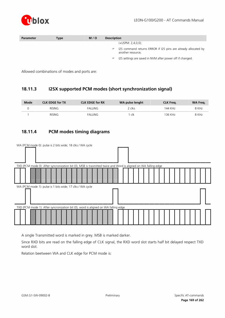
LEON-G100/G200 - AT Commands Manual
GSM.G1-SW-09002-B Preliminary Specific AT-commands
Page 169 of 262
Parameter Type M / O Description
(+USPM: 2,4,0,0);
I2S command returns ERROR if I2S pins are already allocated by another resource;
I2S settings are saved in NVM after power off if changed.
Allowed combinations of modes and ports are:
18.11.3 I2SX supported PCM modes (short synchronization signal)
Mode CLK EDGE for TX CLK EDGE for RX WA pulse lenght CLK Freq. WA Freq.
0 RISING FALLING 2 clks 144 KHz 8 KHz
1 RISING FALLING 1 clk 136 KHz 8 KHz
18.11.4 PCM modes timing diagrams
WA (PCM mode 0): pulse is 2 bits wide; 18 clks / WA cycle
TXD (PCM mode 0): After syncronization bit (0), MSB is trasmitted twice and Word is aligned on WA falling edge
WA (PCM mode 1): pulse is 1 bits wide; 17 clks / WA cycle
TXD (PCM mode 1): After syncronization bit (0), word is aligned on WA falling edge
A single Transmitted word is marked in grey. MSB is marked darker.
Since RXD bits are read on the falling edge of CLK signal, the RXD word slot starts half bit delayed respect TXD
word slot.
Relation beetween WA and CLK edge for PCM mode is:
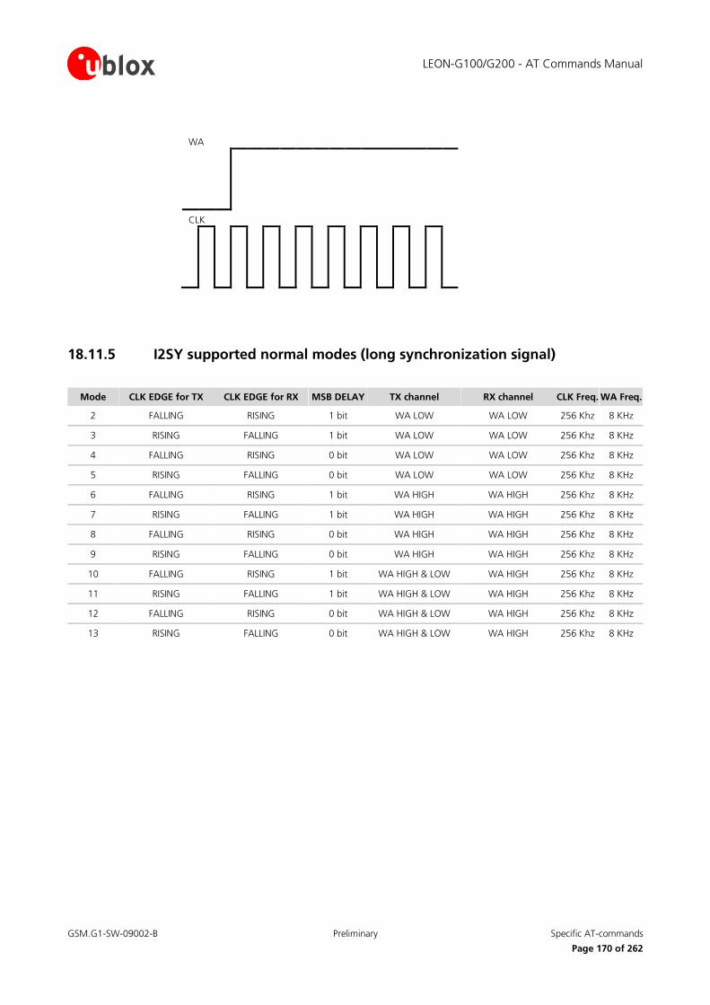
LEON-G100/G200 - AT Commands Manual
GSM.G1-SW-09002-B Preliminary Specific AT-commands
Page 170 of 262
WA
CLK
18.11.5 I2SY supported normal modes (long synchronization signal)
Mode CLK EDGE for TX CLK EDGE for RX MSB DELAY TX channel RX channel CLK Freq. WA Freq.
2 FALLING RISING 1 bit WA LOW WA LOW 256 Khz 8 KHz
3 RISING FALLING 1 bit WA LOW WA LOW 256 Khz 8 KHz
4 FALLING RISING 0 bit WA LOW WA LOW 256 Khz 8 KHz
5 RISING FALLING 0 bit WA LOW WA LOW 256 Khz 8 KHz
6 FALLING RISING 1 bit WA HIGH WA HIGH 256 Khz 8 KHz
7 RISING FALLING 1 bit WA HIGH WA HIGH 256 Khz 8 KHz
8 FALLING RISING 0 bit WA HIGH WA HIGH 256 Khz 8 KHz
9 RISING FALLING 0 bit WA HIGH WA HIGH 256 Khz 8 KHz
10 FALLING RISING 1 bit WA HIGH & LOW WA HIGH 256 Khz 8 KHz
11 RISING FALLING 1 bit WA HIGH & LOW WA HIGH 256 Khz 8 KHz
12 FALLING RISING 0 bit WA HIGH & LOW WA HIGH 256 Khz 8 KHz
13 RISING FALLING 0 bit WA HIGH & LOW WA HIGH 256 Khz 8 KHz

LEON-G100/G200 - AT Commands Manual
GSM.G1-SW-09002-B Preliminary Specific AT-commands
Page 171 of 262
18.11.6 Normal I2S modes timing diagrams
WA (all normal modes)
TXD timeslot (Normal modes 2-3): 1 bit delay; channel on WA low
TXD timeslot (Normal modes 4-5): 0 bit delay; channel on WA low
TXD (Normal modes 6-7):1 bit delay; channel on WA high
TXD (Normal modes 8-9): 0 bit delay; channel on WA high
TXD (Normal modes 10-11):1 bit delay; channel on WA high and low
TXD (Normal modes 12-13): 0 bit delay; channel on WA high and low
A single Transmitted word is marked in grey. MSB is marked darker.
Since RXD bits are read on the opposite edge of CLK signal respect TXD bits, the RXD word slot starts half bit
delayed respect TXD word slot.

LEON-G100/G200 - AT Commands Manual
GSM.G1-SW-09002-B Preliminary Specific AT-commands
Page 172 of 262
Relation beetween WA and CLK edge for Normal I2S depends on mode:
WA WA
CLK (modes 3,5,7,9,11,13) CLK (modes 2,4,6,8,10)
18.12 Audio Path mode setting (Set Path Mode) +USPM
18.12.1 Description
Sets the audio Path Mode. The path mode is the way of enabling the different audio paths (audio input and
output) of LEON for different usecases.
Type Syntax Response Example
Set AT+USPM=<main_uplink>,<main_downlink>,<alert_sound>,<headset_indication>
OK AT+USPM=1,1,0,0
OK
Read AT+USPM? +USPM= <main_uplink>, <main_downlink>, <alert_sound>, <headset_indication>
OK
+USPM: 0,0,1,1
OK
Test AT+USPM=? +USPM: (list of supported <main_uplink>s),(list of supported <main_downlink>s),(list of supported <alert_sound>s),(list of supported <headset_indication>s)
OK
+USPM: (0-2),(0,1,3,4),(0-1),(0-1)
OK
18.12.2 Defined Values
Parameter Type M / O Description
<main_uplink> Integer Specifies the audio output path used for speech
0: Handset microphone (pins MIC_BIAS1, MIC_GND1) (default value)
1: Headset microphone (pins MIC_BIAS2, MIC_GND2)
2: I2S input line (pin I2S_RXD)
<main_downlink> Integer Specifies the audio input path used for speech
0: Normal earpiece (pins of Board-to-Board connector: HS_P and GND) (default value)
1: Mono headset (pins of Board-to-Board connector: HS_P and GND)
2: Stereo headset
3: Loudspeaker (pins of Board-to-Board connector: SPK_P and SPK_N)

LEON-G100/G200 - AT Commands Manual
GSM.G1-SW-09002-B Preliminary Specific AT-commands
Page 173 of 262
Parameter Type M / O Description
4: I2S output line (pin I2S_TXD).
On LEON all audio outputs are supported; the supported audio inputs are Normal earpiece, mono headset and loudspeaker.
<alert_sound> Integer Specifies if the alert sounds in idle mode are played on the main downlink path (same downlink path as speech ; see <main_downlink> parameter) or on the loudspeaker:
0: Main downlink path
1: Loudspeaker (default value)
<headset_indication> Integer Specifies if the speech path is switched on headset or not when the headset is inserted:
0: Headset indication not considered
1: Headset indication considered (default value).
<error> String If an incorrect number of parameters is provided or the parameter values are out of range the message error “operation not supported” will be provided.
The following combination of parameters are allowed:
0, 0, 0, 1: Handset microphone, Normal earpiece, Alert on main path, Headset indication considered
0, 0, 1, 1: Handset microphone, Normal earpiece, Alert on loudspeaker, Headset indication considered
0, 0, 0, 0: Handset microphone, Normal earpiece, Alert on main path , Headset indication not considered
0, 0, 1, 0: Handset microphone, Normal earpiece, Alert on loudspeaker, Headset indication not considered
0, 3, 0, 0: Handset microphone, Loudspeaker, Alert on main path , Headset indication not considered
0, 3, 0, 1: Handset microphone, Loudspeaker, Alert on main path ,Headset indication considered
0, 1, 0, 0: Handset microphone, Mono headset, Alert on main path, Headset indication not considered
1, 1, 0, 0: Headset microphone, Mono headset, Alert on main path, Headset indication not considered
1, 0, 0, 0: Headset microphone, Normal earpiece, Alert on main path, Headset indication not considered
1, 0, 1, 0: Headset microphone, Normal earpiece, Alert on loudspeaker, Headset indication not considered
1, 3, 0, 0: Headset microphone, Loudspeaker, Alert on main path, Headset indication not considered
2, 4, 0, 0: I2S input, I2S output, Alert on main path, Headset indication not considered
18.13 Play audio resource (Play Audio Resource) +UPAR
18.13.1 Description
Starts the playback of the pre-defined tone of the selected audio resource.
Type Syntax Response Example
Set AT+UPAR=<audio_resource>,<tone_id>,<nof_repeats>
OK AT+UPAR=1,1,0
OK
Test AT+UPAR=? +UPAR: (list of supported <audio_resource>s),(list of supported <tone_id>s),(list of supported <nof_repeats>s)
OK
+UPAR: (0-1),(0-255),(0-255)
OK
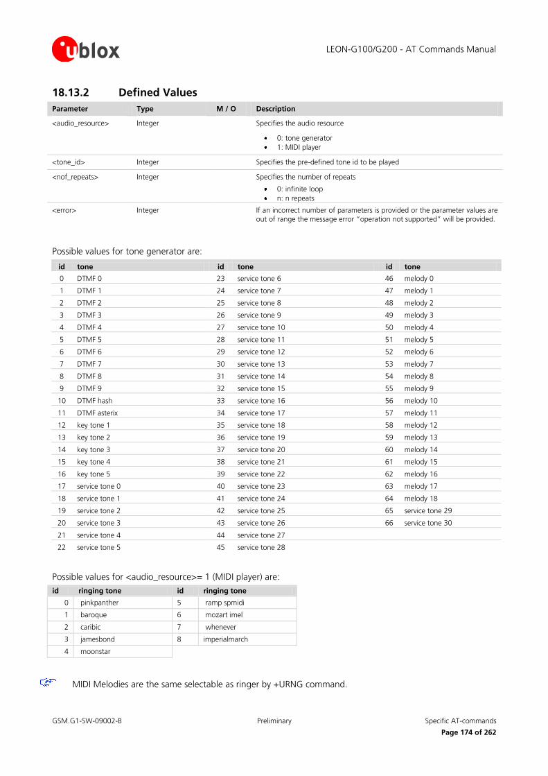
LEON-G100/G200 - AT Commands Manual
GSM.G1-SW-09002-B Preliminary Specific AT-commands
Page 174 of 262
18.13.2 Defined Values
Parameter Type M / O Description
<audio_resource> Integer Specifies the audio resource
0: tone generator
1: MIDI player
<tone_id> Integer Specifies the pre-defined tone id to be played
<nof_repeats> Integer Specifies the number of repeats
0: infinite loop
n: n repeats
<error> Integer If an incorrect number of parameters is provided or the parameter values are out of range the message error “operation not supported” will be provided.
Possible values for tone generator are:
id tone id tone id tone
0 DTMF 0 23 service tone 6 46 melody 0
1 DTMF 1 24 service tone 7 47 melody 1
2 DTMF 2 25 service tone 8 48 melody 2
3 DTMF 3 26 service tone 9 49 melody 3
4 DTMF 4 27 service tone 10 50 melody 4
5 DTMF 5 28 service tone 11 51 melody 5
6 DTMF 6 29 service tone 12 52 melody 6
7 DTMF 7 30 service tone 13 53 melody 7
8 DTMF 8 31 service tone 14 54 melody 8
9 DTMF 9 32 service tone 15 55 melody 9
10 DTMF hash 33 service tone 16 56 melody 10
11 DTMF asterix 34 service tone 17 57 melody 11
12 key tone 1 35 service tone 18 58 melody 12
13 key tone 2 36 service tone 19 59 melody 13
14 key tone 3 37 service tone 20 60 melody 14
15 key tone 4 38 service tone 21 61 melody 15
16 key tone 5 39 service tone 22 62 melody 16
17 service tone 0 40 service tone 23 63 melody 17
18 service tone 1 41 service tone 24 64 melody 18
19 service tone 2 42 service tone 25 65 service tone 29
20 service tone 3 43 service tone 26 66 service tone 30
21 service tone 4 44 service tone 27
22 service tone 5 45 service tone 28
Possible values for <audio_resource>= 1 (MIDI player) are:
id ringing tone id ringing tone
0 pinkpanther 5 ramp spmidi
1 baroque 6 mozart imel
2 caribic 7 whenever
3 jamesbond 8 imperialmarch
4 moonstar
MIDI Melodies are the same selectable as ringer by +URNG command.

LEON-G100/G200 - AT Commands Manual
GSM.G1-SW-09002-B Preliminary Specific AT-commands
Page 175 of 262
18.14 Stop audio resource (Stop Audio Resource) +USAR
18.14.1 Description
This command stops the playback of the selected audio resource.
Type Syntax Response Example
Set AT+USAR=<audio_resource> OK AT+USAR=1
OK
Test AT+USAR=? +USAR: (list of supported <audio_resource>s)
OK
+USAR: (0-1)
OK
18.14.2 Defined Values
Parameter Type M / O Description
<audio_resource> Integer Specifies the audio resource
0: DSP tone generator
1: MIDI player
<error> Integer If an incorrect number of parameters is provided or the parameter values are out of range the message error “operation not supported” will be provided.
18.15 Play AMR audio file +UPLAYFILE
18.15.1 Description
Play the specified AMR audio file stored into the file system. For more details about file system description refer to “File System AT commands” 19.
When finish playing the file, a status indication is sent to DTE in a form of +UPLAYFILE.
Type Syntax Response Example
Set AT+UPLAYFILE=<filename> OK AT+UPLAYFILE=“file1.amr“
OK
Test AT+UPLAYFILE? +UPLAYFILE: <playstatus>
OK
+UPLAYFILE: 0
OK
18.15.2 Defined Values
Parameter Type M / O Description
<audio_resource> Integer Specifies the audio resource
0: DSP tone generator
1: MIDI player

LEON-G100/G200 - AT Commands Manual
GSM.G1-SW-09002-B Preliminary Specific AT-commands
Page 176 of 262
Parameter Type M / O Description
<playstatus> Integer Play status
0: no file is playing
1: the file is playing
<error> Integer If an incorrect number of parameters is provided or the parameter values are out of range the message error “operation not supported” will be provided.
If <filename> file is not present in the file system the message error “FILE NOT FOUND” will be provided.
18.16 Stop AMR audio file +USTOPFILE
18.16.1 Description
Stop the AMR audio file reproduction.
Type Syntax Response Example
Set AT+USTOPFILE OK AT+USTOPFILE
OK
18.17 Network Congestion Detection +UCD
18.17.1 Description
The feature consists in detecting, at radio resource level, an anomalous source of interference and signaling it to
the client. The congestion condition occurs when simultaneously:
The MT has lost synchronization with the serving cell and cannot select any other suitable cell;
The band scan reveals at least n carriers with power level equal or higher than threshold;
On all such carriers, no synchronization is possible.
The number of minimum disturbing carriers and the power level threshold can be configured by the client
through this command.
The congestion condition is cleared when any of the above mentioned statements does not hold.
This command configures the congestion reporting feature. If activated, an unsolicited indication is issued when the congestion condition is entered or released. In particular, the set command controls the presentation of an
URC +UCD:<active>.
Type Syntax Response Example
Set AT+UCD=<enable> [,<min_number_of_carriers>,<rxlev_threshold>]
OK AT+UCD=1,10,20
OK
Read AT+UCD? +UCD: <enable>[,<min_number_of_carriers>, <rxlev_threshold>]
OK
+UCD: <enable>[,<min_number_of_carriers>, <rxlev_threshold>]
OK

LEON-G100/G200 - AT Commands Manual
GSM.G1-SW-09002-B Preliminary Specific AT-commands
Page 177 of 262
Type Syntax Response Example
Test AT+UCD=? +UCD: (range of supported <enable>), (range of supported <min_number_of_carriers>), (range of supported <rxlev_threshold>)
OK
+UCD: (range of supported <enable>), (range of supported <min_number_of_carriers>), (range of supported <rxlev_threshold>)
OK
URC URC +UCD=<active> +UCD=1
18.17.2 Defined Values
Parameter Type M / O Description
<enable> Integer 0: disable congestion URC
1: enable congestion URC +UCD:<active>
<min_number_ of_carriers>
Integer Mandatory parameter when <enable>=1
Range between 1 and 255
<rxlev_threshold> Integer Mandatory parameter when <enable>=1
Range between 3 to 63
<active> Integer <active>=1 when the MT enters in the congestion condition
<active>=0 when the MT exits in the congestion condition
18.18 Select GSM Band +UBANDSEL
18.18.1 Description
Allows to switch from automatic band selection to selection of one or more (up to four) bands from the
following:
850 MHz;
900 MHz;
1800 MHz;
1900 MHz.
The MT will camp on a cell, if suitable, belonging to one of the selected band; the OK response is regardless of the result of the camping on the new cell.
Type Syntax Response Example
Set AT+UBANDSEL=[<band_1>[,<band_2>[,<band_3>[,<band_4>]]]]
OK AT+UBANDSEL=900
OK
Read AT+UBANDSEL? +UBANDSEL: <band_1>[,<band_2>[,<band_3>[,<band_4>]]]
OK
+UBANDSEL: 850,900,1800,1900
OK
Test AT+UBANDSEL=? +UBANDSEL: (list of supported <band_x>)
OK
+UBANDSEL: (0,850,900,1800,1900)
OK

LEON-G100/G200 - AT Commands Manual
GSM.G1-SW-09002-B Preliminary Specific AT-commands
Page 178 of 262
18.18.2 Defined Values
Parameter Type M / O Description
<band_1> or <band_2> or <band_3> or <band_4>
Integer 0: restore the default configuration of the data module
850: selection of 850 MHz band
900: selection of 900 MHz band
1800: selection of 1800 MHz band
1900: selection of 1900 MHz band
18.19 Set reporting call status +UCALLSTAT
18.19.1 Description
Allows to enable / disable the reporting voice call status on DTE using an URC +UCALLSTAT. This code may be
repeated so that for each call one line is displayed on DTE (e.g. one call is active and one call is waiting, or up to
6 calls are active in a multiparty session).
Type Syntax Response Example
Set AT+UCALLSTAT=<enable> OK AT+UCALLSTAT=1
OK
Read AT+UCALLSTAT? +UCALLSTAT: <enable>
OK
+UCALLSTAT: 0
OK
Test AT+UCALLSTAT=? +UCALLSTAT: (list of supported <enable>’s)
OK
+UCALLSTAT: (0-1)
OK
URC +UCALLSTAT: <call_id><stat> +UCALLSTAT: 1,2
18.19.2 Defined Values
Parameter Type M / O Description
<enable> Integer 0: reporting disabled
1: reporting enabled
<call_id> Indicates the call identification (refer to [15])
<stat> Indicates the voice call status
0: active
1: hold
2: dialling (Mobile Originated call)
3: alerting (Mobile Originated call; ringing for the remote party)
4: ringing (Mobile Terminated call)
5: waiting (Mobile Terminated call)
6: disconnected
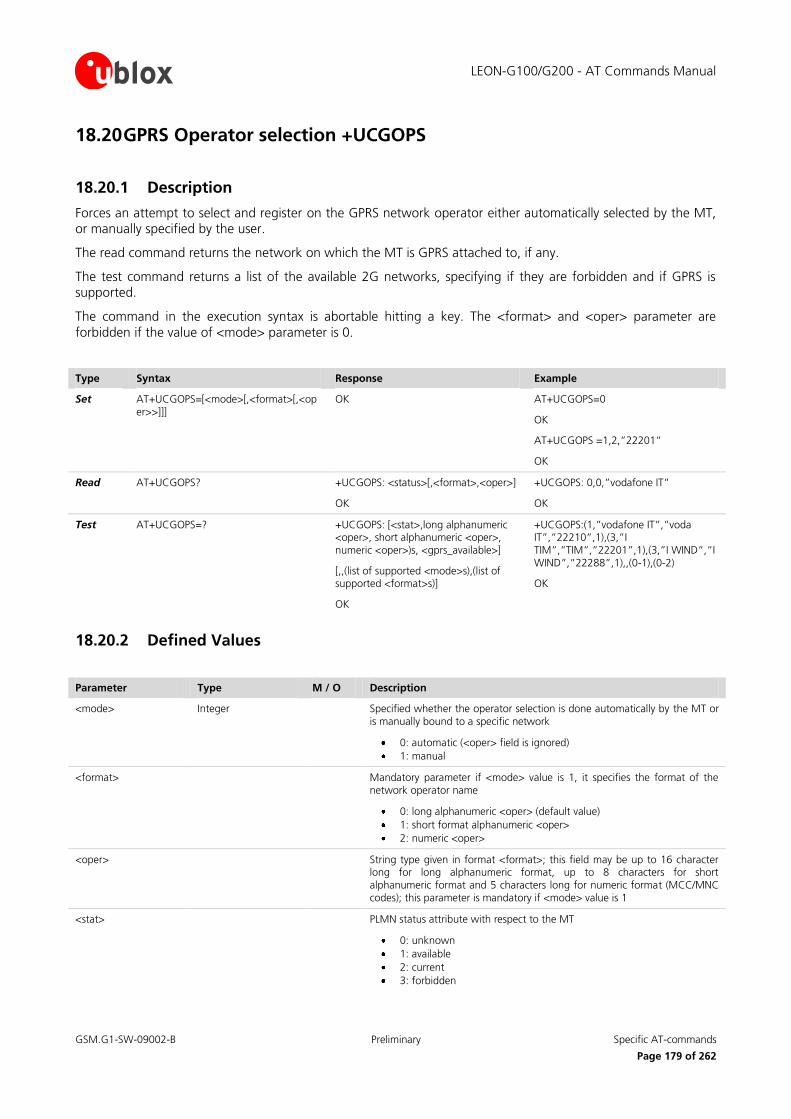
LEON-G100/G200 - AT Commands Manual
GSM.G1-SW-09002-B Preliminary Specific AT-commands
Page 179 of 262
18.20 GPRS Operator selection +UCGOPS
18.20.1 Description
Forces an attempt to select and register on the GPRS network operator either automatically selected by the MT, or manually specified by the user.
The read command returns the network on which the MT is GPRS attached to, if any.
The test command returns a list of the available 2G networks, specifying if they are forbidden and if GPRS is supported.
The command in the execution syntax is abortable hitting a key. The <format> and <oper> parameter are
forbidden if the value of <mode> parameter is 0.
Type Syntax Response Example
Set AT+UCGOPS=[<mode>[,<format>[,<oper>>]]]
OK AT+UCGOPS=0
OK
AT+UCGOPS =1,2,”22201”
OK
Read AT+UCGOPS? +UCGOPS: <status>[,<format>,<oper>]
OK
+UCGOPS: 0,0,”vodafone IT”
OK
Test AT+UCGOPS=? +UCGOPS: [<stat>,long alphanumeric <oper>, short alphanumeric <oper>, numeric <oper>)s, <gprs_available>]
[,,(list of supported <mode>s),(list of supported <format>s)]
OK
+UCGOPS:(1,”vodafone IT”,”voda IT”,”22210”,1),(3,”I TIM”,”TIM”,”22201”,1),(3,”I WIND”,”I WIND”,”22288”,1),,(0-1),(0-2)
OK
18.20.2 Defined Values
Parameter Type M / O Description
<mode> Integer Specified whether the operator selection is done automatically by the MT or is manually bound to a specific network
0: automatic (<oper> field is ignored)
1: manual
<format> Mandatory parameter if <mode> value is 1, it specifies the format of the network operator name
0: long alphanumeric <oper> (default value)
1: short format alphanumeric <oper>
2: numeric <oper>
<oper> String type given in format <format>; this field may be up to 16 character long for long alphanumeric format, up to 8 characters for short alphanumeric format and 5 characters long for numeric format (MCC/MNC codes); this parameter is mandatory if <mode> value is 1
<stat> PLMN status attribute with respect to the MT
0: unknown
1: available
2: current
3: forbidden
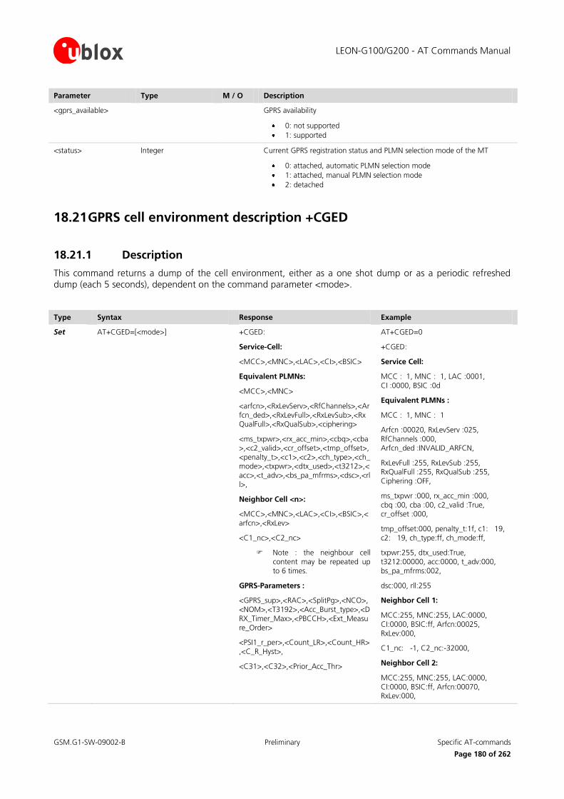
LEON-G100/G200 - AT Commands Manual
GSM.G1-SW-09002-B Preliminary Specific AT-commands
Page 180 of 262
Parameter Type M / O Description
<gprs_available>
GPRS availability
0: not supported
1: supported
<status> Integer Current GPRS registration status and PLMN selection mode of the MT
0: attached, automatic PLMN selection mode
1: attached, manual PLMN selection mode
2: detached
18.21 GPRS cell environment description +CGED
18.21.1 Description
This command returns a dump of the cell environment, either as a one shot dump or as a periodic refreshed dump (each 5 seconds), dependent on the command parameter <mode>.
Type Syntax Response Example
Set AT+CGED=[<mode>] +CGED:
Service-Cell:
<MCC>,<MNC>,<LAC>,<CI>,<BSIC>
Equivalent PLMNs:
<MCC>,<MNC>
<arfcn>,<RxLevServ>,<RfChannels>,<Arfcn_ded>,<RxLevFull>,<RxLevSub>,<RxQualFull>,<RxQualSub>,<ciphering>
<ms_txpwr>,<rx_acc_min>,<cbq>,<cba>,<c2_valid>,<cr_offset>,<tmp_offset>,<penalty_t>,<c1>,<c2>,<ch_type>,<ch_mode>,<txpwr>,<dtx_used>,<t3212>,<acc>,<t_adv>,<bs_pa_mfrms>,<dsc>,<rll>,
Neighbor Cell <n>:
<MCC>,<MNC>,<LAC>,<CI>,<BSIC>,<arfcn>,<RxLev>
<C1_nc>,<C2_nc>
Note : the neighbour cell content may be repeated up to 6 times.
GPRS-Parameters :
<GPRS_sup>,<RAC>,<SplitPg>,<NCO>,<NOM>,<T3192>,<Acc_Burst_type>,<DRX_Timer_Max>,<PBCCH>,<Ext_Measure_Order>
<PSI1_r_per>,<Count_LR>,<Count_HR>,<C_R_Hyst>,
<C31>,<C32>,<Prior_Acc_Thr>
AT+CGED=0
+CGED:
Service Cell:
MCC : 1, MNC : 1, LAC :0001, CI :0000, BSIC :0d
Equivalent PLMNs :
MCC : 1, MNC : 1
Arfcn :00020, RxLevServ :025, RfChannels :000, Arfcn_ded :INVALID_ARFCN,
RxLevFull :255, RxLevSub :255, RxQualFull :255, RxQualSub :255, Ciphering :OFF,
ms_txpwr :000, rx_acc_min :000, cbq :00, cba :00, c2_valid :True, cr_offset :000,
tmp_offset:000, penalty_t:1f, c1: 19, c2: 19, ch_type:ff, ch_mode:ff,
txpwr:255, dtx_used:True, t3212:00000, acc:0000, t_adv:000, bs_pa_mfrms:002,
dsc:000, rll:255
Neighbor Cell 1:
MCC:255, MNC:255, LAC:0000, CI:0000, BSIC:ff, Arfcn:00025, RxLev:000,
C1_nc: -1, C2_nc:-32000,
Neighbor Cell 2:
MCC:255, MNC:255, LAC:0000, CI:0000, BSIC:ff, Arfcn:00070, RxLev:000,

LEON-G100/G200 - AT Commands Manual
GSM.G1-SW-09002-B Preliminary Specific AT-commands
Page 181 of 262
Type Syntax Response Example
C1_nc: -1, C2_nc:-32000,
GPRS-Parameters:
GPRS_sup:True, RAC:01, SplitPg:False, NCO:00000, NOM:001, T3192:01f4,
Acc_Burst_type:00015, DRX_Timer_Max:00, PBCCH:False, Ext_Measure_Order:00000,
PSI1_r_per:00, Count_LR:00, Count_HR:01, C_R_Hyst:00,
C31: -1, C32: 19, Prior_Acc_Thr:06
OK
Read AT+CGED? +CGED: <mode>
OK
+CGED: 0
OK
Test AT+CGED=? +CGED: (list of supported <mode>s)
OK
+CGED: (0-2)
OK
18.21.2 Defined Values
Parameter Type M / O Description
<mode> Integer 0: one shot dump
1: periodic refreshed dump
2: stop periodic dump
<MCC> Integer Mobile country code, range 0-999 (3 digits)
<MNC> Integer Mobile network code, range 0-999 (2 or 3 digits)
<LAC> Integer Location area code, range 0h-FFFFh (2 octets)
<CI> Integer Cell Identity, range 0h-FFFFh (2 octets)
<BSIC> Integer Base Station Identify Code, range 0h-3Fh (6bits)
<arfcn> Integer absolute radio frequency channel number, range 0-1023
<RxLevServ> Integer Received signal level on the cell, range 0-63; please refer to [28]
<RfChannels> Integer number of frequencies in Mobile Allocation: 0x01 if single RF and 0 if n.a.; please refer to [40]
<Arfcn_ded> Integer single ARFCN of dedicated channel; it’s the first ARFCN of Mobile Allocation
<RxLevFull> Integer Received signal strength on serving cell, measured on all slots; range 0h-3Fh; please refer to [40]
<RxLevSub> Integer Received signal strength on serving cell, measured on a subset of slots; range 0h-3Fh; please refer to [40]
<RxQualFull> Integer Received signal quality on serving cell, measured on all slots; range 0-7; please refer to [40]
<RxQualSub> Integer Received signal quality on serving cell, measured on a subset of slots, range 0-7; please refer to [40]
<ciphering> Integer The GSM Ciphering may be ON or OFF
<ms_txpwr> Integer Maximum TX power level a MT may use when accessing the system until otherwise commanded, range 0-31; please refer to [40]
<rx_acc_min> Integer RXLEV-ACCESS-MIN, range 0-63; please refer to [40]
<cbq> Integer CELL_BAR_QUALIFY, range 0-1; please refer to [28]

LEON-G100/G200 - AT Commands Manual
GSM.G1-SW-09002-B Preliminary Specific AT-commands
Page 182 of 262
Parameter Type M / O Description
<cba> Integer CELL_BAR_ACCESS, range 0-1; please refer to [28]
<c2_valid> Integer True if all parameter for calculation of c2 are available; range 0-1
<cr_offset> Integer CELL_RESELECT_OFFSET, range 0-63 (6 bit) ; please refer to [40]
<tmp_offset> Integer TEMPORARY_OFFSET, range 0-7; please refer to [40]
<penalty_t> Integer Penalty time, range 0-31; please refer to [40]
<c1>, <C1_nc> Integer Value of c1; please refer to [28]
<c2>, <C2_nc> Integer Value of c2; please refer to [28]
<ch_type> Integer Channel type of the current connection (please refer to [40]):
0: invalid channel type
1: TCH/F
2: TCH/H
3: SDCCH/4
4: SDCCH/8
<ch_mode> Integer Channel mode of current connection (please refer to [40]):
0: signalling only
1: speech full rate
2: speech half rate
3: data full rate, 12.0 kbit/s radio interface rate
4: data full rate, 6.0 kbit/s radio interface rate
5: data half rate, 6.0 kbit/s radio interface rate
6: data full rate, 3.6 kbit/s radio interface rate
7: data half rate, 3.6 kbit/s radio interface rate
8: speech full rate version 2
9: speech full rate version 3
10: speech half rate version 2
11: speech half rate version 3
<txpwr> Integer Transmit power level of the current connection, range 0-31; please refer to [40]
<dtx_used> Integer DTX used, range 0-1; please refer to [40]
<t3212> Integer T3212. The T3212 timeout value field is coded as the binary representation of the timeout value for periodic updating in decihours; range 0-255 (8 bits); please refer to [40]
<acc> Integer Access control class (RACH Control Parameters); please refer to [40]
<t_adv> Integer Timing Advance, it is valid during a connection and it will updated during the next connection; please refer to [40]
<bs_pa_mfrms> Integer BS_PA_MFRMS (multiframes period for transmission of PAGING REQUEST), range 0-7 mapped to 2-9; please refer to [42]
<dsc> Integer Downlink Signaling Counter
<rll> Radio Link Loss Counter
GPRS-Parameters:
Parameter Type M / O Description
<GPRS_sup> Integer GPRS supported (in serving cell); range 0-1; please refer to [40]
<RAC> Integer Routing Area Code, range 0h-FFh (1 octet); please refer to [40]
<SplitPg> Integer SPGC_CCCH_SUP split pg_cycle on ccch by network, range 0-1 (2 bits); please refer to [40]
<NCO> Integer NETWORK_CONTROL_ORDER (GPRS_Cell_Options), range 0-3 (2 bits); please refer to [40]
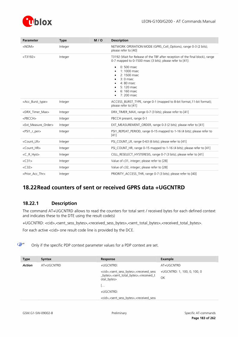
LEON-G100/G200 - AT Commands Manual
GSM.G1-SW-09002-B Preliminary Specific AT-commands
Page 183 of 262
Parameter Type M / O Description
<NOM> Integer NETWORK OPERATION MODE (GPRS_Cell_Options), range 0-3 (2 bits); please refer to [40]
<T3192> Integer T3192 (Wait for Release of the TBF after reception of the final block), range 0-7 mapped to 0-1500 msec (3 bits); please refer to [41]:
0: 500 msec
1: 1000 msec
2: 1500 msec
3: 0 msec
4: 80 msec
5: 120 msec
6: 160 msec
7: 200 msec
<Acc_Burst_type> Integer ACCESS_BURST_TYPE, range 0-1 (mapped to 8-bit format,11-bit format); please refer to [41]
<DRX_Timer_Max> Integer DRX_TIMER_MAX, range 0-7 (3 bits); please refer to [41]
<PBCCH> Integer PBCCH present, range 0-1
<Ext_Measure_Order> Integer EXT_MEASUREMENT_ORDER, range 0-3 (2 bits); please refer to [41]
<PSI1_r_per> Integer PSI1_REPEAT_PERIOD, range 0-15 mapped to 1-16 (4 bits); please refer to [41]
<Count_LR> Integer PSI_COUNT_LR, range 0-63 (6 bits); please refer to [41]
<Count_HR> Integer PSI_COUNT_HR, range 0-15 mapped to 1-16 (4 bits); please refer to [41]
<C_R_Hyst> Integer CELL_RESELECT_HYSTERESIS, range 0-7 (3 bits); please refer to [41]
<C31> Integer Value of c31, integer; please refer to [28]
<C32> Integer Value of c32, integer; please refer to [28]
<Prior_Acc_Thr> Integer PRIORITY_ACCESS_THR, range 0-7 (3 bits); please refer to [40]
18.22 Read counters of sent or received GPRS data +UGCNTRD
18.22.1 Description
The command AT+UGCNTRD allows to read the counters for total sent / received bytes for each defined context
and indicates these to the DTE using the result code(s)
+UGCNTRD: <cid>,<sent_sess_bytes>,<received_sess_bytes>,<sent_total_bytes>,<received_total_bytes>.
For each active <cid> one result code line is provided by the DCE.
Only if the specific PDP context parameter values for a PDP context are set.
Type Syntax Response Example
Action AT+UGCNTRD +UGCNTRD:
<cid>,<sent_sess_bytes>,<received_sess_bytes>,<sent_total_bytes>,<received_total_bytes>
[…
+UGCNTRD:
<cid>,<sent_sess_bytes>,<received_sess
AT+UGCNTRD
+UGCNTRD: 1, 100, 0, 100, 0
OK

LEON-G100/G200 - AT Commands Manual
GSM.G1-SW-09002-B Preliminary Specific AT-commands
Page 184 of 262
Type Syntax Response Example
_bytes>,<sent_total_bytes>,<received_total_bytes>]
OK
Test AT+UGCNTRD=? OK
18.22.2 Defined Values
Parameter Type M / O Description
<cid> Integer integer containing the local PDP context identifier in range of 0-3
<sent_sess_bytes> Integer long integer containing the number of sent GPRS session
<received_sess_bytes> Integer long integer containing the number of received GPRS session bytes
<sent_total_bytes> Integer long integer containing the total number of sent bytes
<received_total_bytes> Integer long integer containing the number of total received bytes
18.23 Set/reset counter of sent or received GPRS data +UGCNTSET
18.23.1 Description
The command AT+UGCNTSET allows to set the counter for total sent/received bytes for each defined context to
zero or any other offset value.
Note:
Whenever the total counter for a <cid> is set (to zero or a certain value), the session counter for this <cid> will be set to zero.
If the <cid> equals zero than the total counter for every defined context is set to zero.
Given offset parameters are ignored in this case.
Type Syntax Response Example
Set AT+UGCNTSET=<cid>,[<total_bytes_sent_offset>,<total_bytes_received_offset>]
OK AT+UGCNTSET=1,20,20
OK
Test AT+UGCNTSET=? +UGCNTSET: (range of <cid>s),(range of <total_bytes_sent_offset>),(range of <total_bytes_received_offset>)
OK
AT+UGCNTSET=1,20,20
OK
18.23.2 Defined Values
Parameter Type M / O Description
<cid> Integer integer containing the local PDP context identifier in range of 0-3
<total_bytes_sent_offset> Integer long integer containing the offset of total sent bytes used for counting in range 0-0x7FFFFFFE
<total_bytes_received_offset> Integer long integer containing the offset of total received bytes used for counting in range 0-0x7FFFFFFE.

LEON-G100/G200 - AT Commands Manual
GSM.G1-SW-09002-B Preliminary Specific AT-commands
Page 185 of 262
18.24 Read remaining SIM PIN attempts +UPINCNT
18.24.1 Description
Reads the remaining attempts for SIM PIN, SIM PIN2, SIM PUK and SIM PUK2.
Type Syntax Response Example
Action AT+UPINCNT +UPINCNT: <PIN attempts>, <PIN2 attempts>, <PUK attempts>, <PUK2 attempts>
OK
Test AT+UPINCNT=? OK OK
18.24.2 Defined Values
Parameter Type M / O Description
<PIN attempts> Integer number of remaining attempts to enter PIN (default 3)
<PIN2 attempts> Integer number of remaining attempts to enter PIN2 (default 3)
<PUK attempts> Integer number of remaining attempts to enter PUK (default 10)
<PUK2 attempts> Integer number of remaining attempts to enter PUK2 (default 10)
18.25 Help displaying all commands &H
18.25.1 Description
This command allows to list all possible commands.
Type Syntax Response Example
Action AT&H <AT command 1>[, <AT command 2>[…]]
OK
18.25.2 Defined Values
Parameter Type M / O Description
<AT command n> AT command name

LEON-G100/G200 - AT Commands Manual
GSM.G1-SW-09002-B Preliminary File System AT Commands
Page 186 of 262
19 File System AT Commands
19.1 Download file +UDWNFILE
19.1.1 Description
Stores (writes) a file into the file system. The available free memory space is checked before starting the file
transfer. If the file exceeds the available space an error is returned. If the file already exists it will be overwritten.
No interrogation (test) is possible for this command. In case of any error, the return code will always be 100
(“unknown”) or 4 (“ERROR”). If an error occurs during the file writing, the transfer is aborted and it is up to the
user to delete the file.
Note:
The maximal speed of the serial port is 115200 bps.
The maximum available user space in the file system is 1MB.
Type Syntax Response Example
Set AT+UDWNFILE=<filename>, <size>
>
Start transfer of file data
OK
AT+UDWNFILE=”filename”,36
>these bytes are the data of the file
OK
19.1.2 Defined Values
Parameter Type M / O Description
<filename> String M file name (max. 47 characters)
<size> Integer M file size expressed in bytes
Note:
The stream of bytes can be entered after the “>” prompt has been provided to the user. The file transfer is
terminated exactely when <size> bytes have been sent entered and either OK or an error message is returned.
The feed process cannot be interrupted i.e. command mode is re-entered once the user has provided the declared the number of bytes.
19.2 Delete file +UDELFILE
19.2.1 Description
Deletes a stored file from the file system.
Type Syntax Response Example
Set AT+UDELFILE=<filename> OK AT+UDELFILE=”filename”

LEON-G100/G200 - AT Commands Manual
GSM.G1-SW-09002-B Preliminary File System AT Commands
Page 187 of 262
19.2.2 Defined Values
Parameter Type M / O Description
<filename> String M file name (max. 47 characters)
19.3 Read file +URDFILE
19.3.1 Description
Retrieves a file from the file system.
Type Syntax Response Example
Set AT+URDFILE=<filename> +URDFILE: <filename>,<size>,<data>
OK
AT+URDFILE=”filename”
+URDFILE: “filename”,36, “these bytes are the data of the file”
OK
19.3.2 Defined Values
Parameter Type M / O Description
<filename> String M file name (max. 47 characters)
<size> Integer M file size, in bytes
<data> content of the file read
Note:
The returned file data is displayed as an ASCII string of <length> chars in the range [0x00,0xFF] . At the end of
the string, <CR><LF> are provided for user convenience and visualization purposes.
19.4 List files +ULSTFILE
19.4.1 Description
Retrieve a list of files (file names) stored in the file system.
Type Syntax Response Example
Set AT+ULSTFILE= +ULSTFILE: [<filename1>[,<filename2>[,…[,<filenameN>]]]]
AT+ULSTFILE=
+ULSTFILE: “filename”
OK
19.4.2 Defined Values
Parameter Type M / O Description
<filenameX> String file name (max. 47 characters)

LEON-G100/G200 - AT Commands Manual
GSM.G1-SW-09002-B Preliminary Audio parameters tuning commands
Page 188 of 262
20 Audio parameters tuning commands
20.1 Introduction
The audio driver switches uplink and downlink audio paths. For example uplink path can be switched from
handset microphone to headset microphone and downlink path can be switched from handset earpiece to
loudspeaker. Every path includes a set of parameters that are loaded by the audio driver in the voiceband processing system; for example the uplink path can include the gain of the microphone that can be different for
handset or headset microphone path.
For every audio path, the parameters can be changed by the following AT commands:
AT+UHFP: Hand Free Parameters;
AT+UMGC: Microphone Gain Control;
AT+USGC: Speaker Gain Control;
AT+USTN: Sidetone;
AT+UUBF: Uplink Biquad Filters;
AT+UDBF: Downlink Biquad Filters.
Audio parameters configuration for all the audio paths can be stored in the user profiles in NVRAM (refer to
AT&W command description).
Audio parameters in user profiles in NVRAM are managed by commands AT&W (it saves in profile 0 or profile 1), AT&F (it resets to factory profile), AT&Y (it selects user profile to be used after a hardware reset), ATZ (it reloads
user profile).
AT&V command does not display audio parameters. Audio parameters can be displayed by the corresponding read command, for example AT+UMGC?.
Further explanation on meaning of audio parameters and on their position in the voiceband processing system
can be found in the separate document “Audio driver presentation”.
Audio parameters in the factory profile are stored in static NVRAM and can not be changed by the user. They
can be changed only by the manufacturer (For details on procedure and tool needed, refer to document “Audio
parameters update presentation”).
20.2 Microphone Gain (Microphone Gain Control) +UMGC
20.2.1 Description
Changes the uplink path gain. See note 20.7.2 for impact on echo canceller.
Type Syntax Response Example
Set
AT+UMGC=<uplink_path_num>,<analog_gain>, <digital_gain>
OK AT+UMGC=1,12,16000
OK
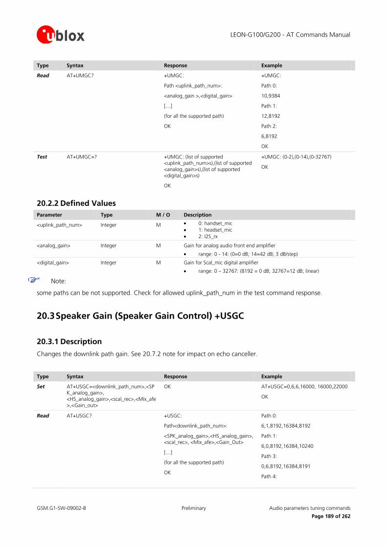
LEON-G100/G200 - AT Commands Manual
GSM.G1-SW-09002-B Preliminary Audio parameters tuning commands
Page 189 of 262
Type Syntax Response Example
Read
AT+UMGC? +UMGC:
Path <uplink_path_num>:
<analog_gain >,<digital_gain>
[…]
(for all the supported path)
OK
+UMGC:
Path 0:
10,9384
Path 1:
12,8192
Path 2:
6,8192
OK
Test
AT+UMGC=? +UMGC: (list of supported <uplink_path_num>s),(list of supported <analog_gain>s),(list of supported <digital_gain>s)
OK
+UMGC: (0-2),(0-14),(0-32767)
OK
20.2.2 Defined Values
Parameter Type M / O Description
<uplink_path_num>
Integer M 0: handset_mic
1: headset_mic
2: I2S_rx
<analog_gain> Integer M Gain for analog audio front end amplifier
range: 0 - 14: (0=0 dB; 14=42 dB; 3 dB/step)
<digital_gain> Integer M Gain for Scal_mic digital amplifier
range: 0 – 32767: (8192 = 0 dB; 32767=12 dB; linear)
Note:
some paths can be not supported. Check for allowed uplink_path_num in the test command response.
20.3 Speaker Gain (Speaker Gain Control) +USGC
20.3.1 Description
Changes the downlink path gain. See 20.7.2 note for impact on echo canceller.
Type Syntax Response Example
Set
AT+USGC=<downlink_path_num>,<SPK_analog_gain>, <HS_analog_gain>,<scal_rec>,<Mix_afe>,<Gain_out>
OK AT+USGC=0,6,6,16000, 16000,22000
OK
Read
AT+USGC? +USGC:
Path<downlink_path_num>:
<SPK_analog_gain>,<HS_analog_gain>,<scal_rec>, <Mix_afe>,<Gain_Out>
[…]
(for all the supported path)
OK
Path 0:
6,1,8192,16384,8192
Path 1:
6,0,8192,16384,10240
Path 3:
0,6,8192,16384,8191
Path 4:

LEON-G100/G200 - AT Commands Manual
GSM.G1-SW-09002-B Preliminary Audio parameters tuning commands
Page 190 of 262
Type Syntax Response Example
6,6,8192,16384,8191
OK
Test
AT+USGC=? +USGC: (list of supported <downlink_path_num>s),(list of supported <SPK_analog_gain>s),(list of supported <HS_analog_gain>s),(list of supported <scal_rec>s),(list of supported <Mix_afe>s),(list of supported <Gain_out>s)
OK
+USGC: (0,1,3,4),(0-6),(0-6),(0-32767),(0-32767),(0-32767)
OK
20.3.2 Defined Values
Parameter Type M / O Description
<downlinkpath_num> Integer M normal_earpiece
1: mono_headset
2: stereo_headset
3: backspeaker
<SPK_analog_gain> Integer M gain of analog audio amplifier for SPK_P/SPK_N output
range: 0 – 6: (-3db/step; 0=0 dB to 6= -18 dB)
<HS_analog_gain> Integer M gain of analog audio amplifier for HS_P output
range: 0 – 6: (-3 db/step; 0=0 dB to 6= -18 dB)
<scal_rec>
Integer M gain for the digital amplifier Scal_rec (speech and Tone Generator)
range: 0 – 32767: (8192=0 dB; 32767=12 dB; linear)
<Mix_afe> Integer M gains for the digital amplifier Mix_afe (synthetizers)
range: 0 – 32767: (16384=0 dB; 32767=6 dB; linear)
<Gain_out> Integer M gain for the digital amplifier Gain_Out (speech)
range: 0 – 32767: (8192=0 dB; 32767=12 dB; linear)
Note:
some paths may be not supported.
20.4 Sidetone (SideToNe) +USTN
20.4.1 Description
Changes the sidetone gain for a specific path.
Type Syntax Response Example
Set
AT+USTN=<downlink_path_num>,<sidetone_gain>
OK AT+USTN=1,1000
OK
Read
AT+USTN? +USTN:
Path<downlink_path_num>:
<sidetone_gain >
[…] (all the supported path)
OK
+USTN:
Path 0:
2249
Path 1:
2249
…….
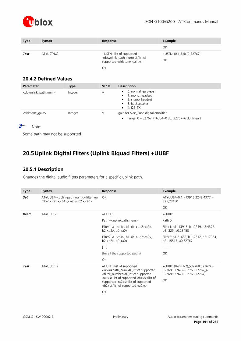
LEON-G100/G200 - AT Commands Manual
GSM.G1-SW-09002-B Preliminary Audio parameters tuning commands
Page 191 of 262
Type Syntax Response Example
OK
Test
AT+USTN=? +USTN: (list of supported <downlink_path_num>s),(list of supported <sidetone_gain>s)
OK
+USTN: (0,1,3,4),(0-32767)
OK
20.4.2 Defined Values
Parameter Type M / O Description
<downlink_path_num>
Integer M 0: normal_earpiece
1: mono_headset
2: stereo_headset
3: backspeaker
4: I2S_TX
<sidetone_gain>
Integer M gain for Side_Tone digital amplifier
range: 0 – 32767: (16384=0 dB; 32767=6 dB; linear)
Note:
Some path may not be supported
20.5 Uplink Digital Filters (Uplink Biquad Filters) +UUBF
20.5.1 Description
Changes the digital audio filters parameters for a specific uplink path.
Type Syntax Response Example
Set
AT+UUBF=<uplinkpath_num>,<filter_number>,<a1>,<b1>,<a2>,<b2>,<a0>
OK AT+UUBF=0,1, -13915,2249,4377, -325,23450
OK
Read
AT+UUBF? +UUBF:
Path =<uplinkpath_num>:
Filter1: a1:<a1>, b1:<b1>, a2:<a2>, b2:<b2>, a0:<a0>
Filter2: a1:<a1>, b1:<b1>, a2:<a2>, b2:<b2>, a0:<a0>
[…]
(for all the supported paths)
OK
+UUBF:
Path 0:
Filter1: a1:-13915, b1:2249, a2:4377, b2:-325, a0:23450
Filter2: a1:21682, b1:-2312, a2:17984, b2:-15517, a0:32767
…….
OK
Test
AT+UUBF=? +UUBF: (list of supported <uplinkpath_num>s),(list of supported <filter_number>s),(list of supported <a1>s),(list of supported <b1>s),(list of supported <a2>s),(list of supported <b2>s),(list of supported <a0>s)
OK
+UUBF: (0-2),(1-2),(-32768:32767),(-32768:32767),(-32768:32767),(-32768:32767),(-32768:32767)
OK

LEON-G100/G200 - AT Commands Manual
GSM.G1-SW-09002-B Preliminary Audio parameters tuning commands
Page 192 of 262
20.5.2 Defined Values
Parameter Type M / O Description
<uplink_path_num>
Integer M 0: handset_mic
1: headset_mic
2: I2S_rx
<filter_number> Integer M Two digital filters in cascade are available for each uplink path (Filter1, Filter2)
<a1>,<b1>,<a2>,<b2>,<a0>
These parameters are the biquad filter coefficient. The biquad filter transfer function is with coefficients A0,A1,A2,B1,B2 in the range -1:1
range: -32768 : 32767
Note:
Some path may not be supported
Example:
Set both headset microphone filters to all pass:
In this case the biquad filter transfer function is
H(z)=1
Then the coefficients are
A0=1
A1=A2=B1=B2=0 a1=a2=b1=b2=0
Commands are:
AT+UUBF=1,1, 0,0,0,0, 32767
AT+UUBF=1,2, 0,0,0,0, 32767
20.6 Downlink Digital Filters (Downlink Biquad Filters) +UDBF
20.6.1 Description
Change the digital audio filters parameters for a specific downlink path.
Type Syntax Response Example
Set
AT+UDBF=<downlinkpath_num>,<filter_number>,<a1>,<b1>,<a2>,<b2>,<a0>
OK AT+UDBF=0,1, -13915,2249,4377, -325,23450
OK
Read
AT+UDBF? +UDBF:
Path =<downlinkpath_num>:
Filter1: a1:<a1>, b1:<b1>, a2:<a2>, b2:<b2>, a0:<a0>
Filter2: a1:<a1>, b1:<b1>, a2:<a2>, b2:<b2>, a0:<a0>
[…] (for all the supported paths)
OK
+UDBF:
Path 0:
Filter1: a1:0, b1:0, a2:0, b2:0, a0:32767
Filter2: a1:0, b1:0, a2:0, b2:0, a0:32767
…….
OK

LEON-G100/G200 - AT Commands Manual
GSM.G1-SW-09002-B Preliminary Audio parameters tuning commands
Page 193 of 262
Type Syntax Response Example
Test
AT+UDBF=? +UDBF: (list of supported <downlinkpath_num>s),(list of supported <filter_number>s),(list of supported <a1>s),(list of supported <b1>s),(list of supported <a2>s),(list of supported <b2>s),(list of supported <a0>s)
OK
+UDBF: (0,1,3,4),(1-2),(-32768:32767),(-32768:32767),(-32768:32767),(-32768:32767),(-32768:32767)
OK
20.6.2 Defined Values
Parameter Type M / O Description
<downlinkpath_num>
Integer M 0: normal_earpiece
1: mono_headset
2: stereo_headset
3: backspeaker
4: I2S_TX
<filter_number> Integer M Two digital filters in cascade are available for each uplink path (Filter1, Filter2)
<a1>,<b1>,<a2>,<b2>,<a0>
These parameters are the biquad filter coefficient. The biquad filter transfer function is with coefficients A0,A1,A2,B1,B2 in the range -1:1
range: -32768 : 32767
Note:
Some path may not be supported
Example:
Set both loudspeaker filters to all pass:
In this case the biquad filter transfer function is
H(z)=1
Then the coefficients are
A0=1
A1=A2=B1=B2=0 a1=a2=b1=b2=0
Commands are:
AT+UDBF=3,1,0,0,0,0, 32767
AT+UDBF=3,2,0,0,0,0, 32767
20.7 Hand Free Parameters (Hand Free Parameters) +UHFP
20.7.1 Description
Changes the parameters that control the Hand Free audio application for a specific uplink path. Handsfree
application consists distinct operating parts:
Echo Canceller (EC);
Automatic Gain Control (AGC);
Noise Suppressor.
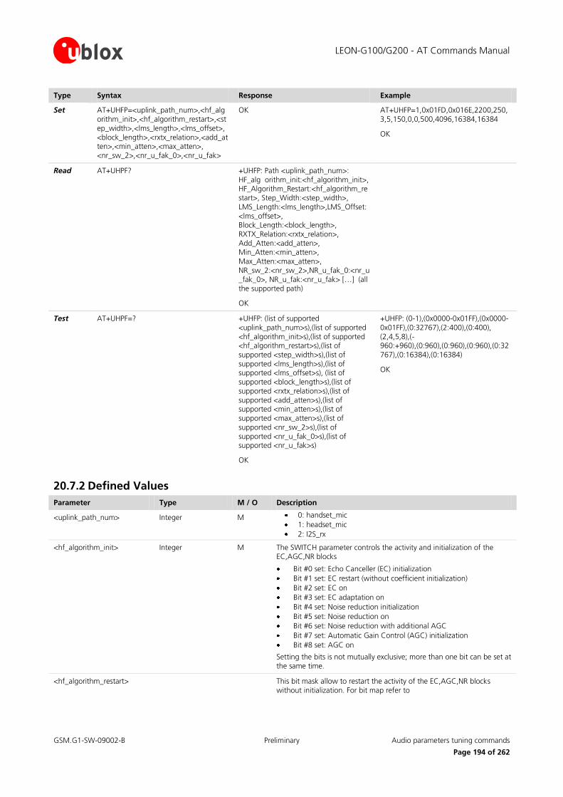
LEON-G100/G200 - AT Commands Manual
GSM.G1-SW-09002-B Preliminary Audio parameters tuning commands
Page 194 of 262
Type Syntax Response Example
Set
AT+UHFP=<uplink_path_num>,<hf_algorithm_init>,<hf_algorithm_restart>,<step_width>,<lms_length>,<lms_offset>,<block_length>,<rxtx_relation>,<add_atten>,<min_atten>,<max_atten>, <nr_sw_2>,<nr_u_fak_0>,<nr_u_fak>
OK AT+UHFP=1,0x01FD,0x016E,2200,250,3,5,150,0,0,500,4096,16384,16384
OK
Read
AT+UHPF? +UHFP: Path <uplink_path_num>: HF_alg orithm_init:<hf_algorithm_init>, HF_Algorithm_Restart:<hf_algorithm_restart>, Step_Width:<step_width>, LMS_Length:<lms_length>,LMS_Offset:<lms_offset>, Block_Length:<block_length>, RXTX_Relation:<rxtx_relation>, Add_Atten:<add_atten>, Min_Atten:<min_atten>, Max_Atten:<max_atten>, NR_sw_2:<nr_sw_2>,NR_u_fak_0:<nr_u_fak_0>, NR_u_fak:<nr_u_fak> […] (all the supported path)
OK
Test
AT+UHPF=? +UHFP: (list of supported <uplink_path_num>s),(list of supported <hf_algorithm_init>s),(list of supported <hf_algorithm_restart>s),(list of supported <step_width>s),(list of supported <lms_length>s),(list of supported <lms_offset>s), (list of supported <block_length>s),(list of supported <rxtx_relation>s),(list of supported <add_atten>s),(list of supported <min_atten>s),(list of supported <max_atten>s),(list of supported <nr_sw_2>s),(list of supported <nr_u_fak_0>s),(list of supported <nr_u_fak>s)
OK
+UHFP: (0-1),(0x0000-0x01FF),(0x0000-0x01FF),(0:32767),(2:400),(0:400), (2,4,5,8),(-960:+960),(0:960),(0:960),(0:960),(0:32767),(0:16384),(0:16384)
OK
20.7.2 Defined Values
Parameter Type M / O Description
<uplink_path_num>
Integer M 0: handset_mic
1: headset_mic
2: I2S_rx
<hf_algorithm_init>
Integer M The SWITCH parameter controls the activity and initialization of the EC,AGC,NR blocks
Bit #0 set: Echo Canceller (EC) initialization
Bit #1 set: EC restart (without coefficient initialization)
Bit #2 set: EC on
Bit #3 set: EC adaptation on
Bit #4 set: Noise reduction initialization
Bit #5 set: Noise reduction on
Bit #6 set: Noise reduction with additional AGC
Bit #7 set: Automatic Gain Control (AGC) initialization
Bit #8 set: AGC on
Setting the bits is not mutually exclusive; more than one bit can be set at the same time.
<hf_algorithm_restart>
This bit mask allow to restart the activity of the EC,AGC,NR blocks without initialization. For bit map refer to

LEON-G100/G200 - AT Commands Manual
GSM.G1-SW-09002-B Preliminary Audio parameters tuning commands
Page 195 of 262
Parameter Type M / O Description
<hf_algorithm_init> used when the algorithm is restarted automatically by the driver (i.e. after and handover)
<step_width>
The higher this value, the faster the echo characteristic gets adapted.
Limit: STEP_WIDTH *BLOCK_LENGTH<=2*32767
<lms_length>
maximum impulsive response of the FIR filter considered by the adaptive LMS algorithm, in samples. (Max time length: 400*Ts=50ms)
Limit:
2<= LMS_LENGTH+ LMS_OFFSET<=400 (DSP memory limit)
<lms_offset>
This parameter is used by the LMS adaptation algorithm and indicates the expected delay of the echo after the RX signal , in samples.
<block_length>
LMS command ent adaptation block I. The higher this number, the slower but more accurate the adaptation converges
<rxtx_relation>
checks the power relation between Rx (loudspeaker) and Tx (microphone) signals in order to recognize the double talk condition from the echo condition. The system is considered to be in double talk condition when the TX power (mic signal) is higher that the maximum expected echo power:
Tx(dB) > Rx (dB) - RxTx(dB) with RxTx(dB)=RXTX_RELATION*3/32
This is the most critical parameter in handfree. Values typical for handset are in range 50 to 150. For backspeaker: -100 to -400. When in double talk, adaptation of FIR and AGC are suspended.
<add_atten> When AGC decides to attenuate, ADD_ATTEN is added to the calculated attenuation.
<min_atten> Minimal attenuation of the mic signal by the AGC.
o Level(dB)=3/32* HF_MIN_ATTEN
<max_atten> Maximal attenuation of the mic signal by the AGC.
o Level(dB)=3/32* HF_MAX_ATTEN
<nr_sw_2>
Max attenuation. Linear; 0x7FFF means 1 (0 dB)
o Ex. 0x4000= 0.5 = -6 dB
<nr_u_fak_0>
Factor of NR in the band 0 (0 Hz - 250 Hz).
o Linear; 0x4000 means 1 (0 dB)
<nr_u_fak> Factor of NR in the bands 1 to 7 (250 Hz - 3750 Hz).
o Linear; 0x4000 means 1 (0 dB) o A factor lower than 1 causes a better NR but also speech
distortion and lowering of SLR.
Note:
Some path may not be supported.
Examples:
1. SWITCH =0x01FD =bin 000111111101 means EC initialized and on, EC adaptation on, Noise reduction
initialized and on, Automatic Gain Control initialized and on,used with NR.
2. SWITCH =0x016E =bin 000101101110 means EC on, EC adaptation on, EC restart Noise reduction on,
Automatic Gain Control on and working with NR.

LEON-G100/G200 - AT Commands Manual
GSM.G1-SW-09002-B Preliminary Audio parameters tuning commands
Page 196 of 262
3. Calculation of <lms_offset>
Sample period T= 1/8000 s= 125 µs Loudspeaker to mic distance on a phone: L= 10 cm
Sound velocity V=340 m/s Delay of echo D =L/V = 0.1/ 340 = 294 µs
Number of samples=D/T= 2.35 --> LMS_OFFSET =2
Important note: Any change in the gain on uplink or downlink path impacts on the amount of echo fed back from the speaker to the microphone .This means that
performance of EC algorithm could change and rxtx_relation parameter could need to be
changed to better fit new gain on uplink or downlink path.

LEON-G100/G200 - AT Commands Manual
GSM.G1-SW-09002-B Preliminary Data Connection Setup AT Commands
Page 197 of 262
21 Data Connection Setup AT Commands LEON provides access to networking services (DNS, TCP/IP, FTP, HTTP, SMTP) by means of several proprietary AT
commands which implemement Data Connection Management (DCM) for both packet switched (GPRS) and circuit switched (GSM) data services. Since there is no intrinsic association between bearers (GPRS and CSD) and
data channels (TCP/IP sockets, DNS service, FTP, HTTP, SMTP) a great flexibility is ensured: several TCP/IP sockets
can be managed independently and simultaneously over the same bearer and it is easy to associate networking services and connections.
The AT commands described in this paragraph define the parameters of PSD and CSD connection, and activate
and deactivate PSD and CSD connections. Networking services such as TCP/IP sockets, FTP, HTTP and SMTP clients can be started by the commands detailed in paragraphs “TCP/IP AT Commands”, “FTP AT Commands”,
“HTTP AT Commands” and “SMTP AT Commands”.
21.1 Packet Switched Data +UPSD
21.1.1 Description
Sets or gets the value of the specified parameter in a specific GPRS packet switched data (PSD) profile, or reads all parameters of the given GPRS profile, and lists them in separated lines.
Note:
The parameter values set with this command are volatile, but the whole profile may be stored in NVM with the
AT+UPSDA command.
Type Syntax Response Example
Set PSD Set command
AT+UPSD=<profile_id>,<param_tag>,<param_val>
PSD Get command
AT+UPSD=<profile_id>, <param_tag>
PSD Get All command
AT+UPSD=<profile_id>
OK
+UPSD: <profile_id>,<param_tag>, <param_val>
OK
+UPSD: <profile_id>,0,<param_val0>
+UPSD: <profile_id>,1,<param_val1>…
+UPSD: <profile_id>,19, <param_val19>
AT+UPSD=0,1,”apn.provider.com”
OK
AT+UPSD=0,1
+UPSD: 0,1,”apn.provider.com”
OK
AT+UPSD=0
+UPSD: 0,0,0
+UPSD: 0,1,”apn.provider.com”
+UPSD: 0,2,”username”
+UPSD: 0,4,”0.0.0.0”
…
+UPSD: 0,19,0
OK
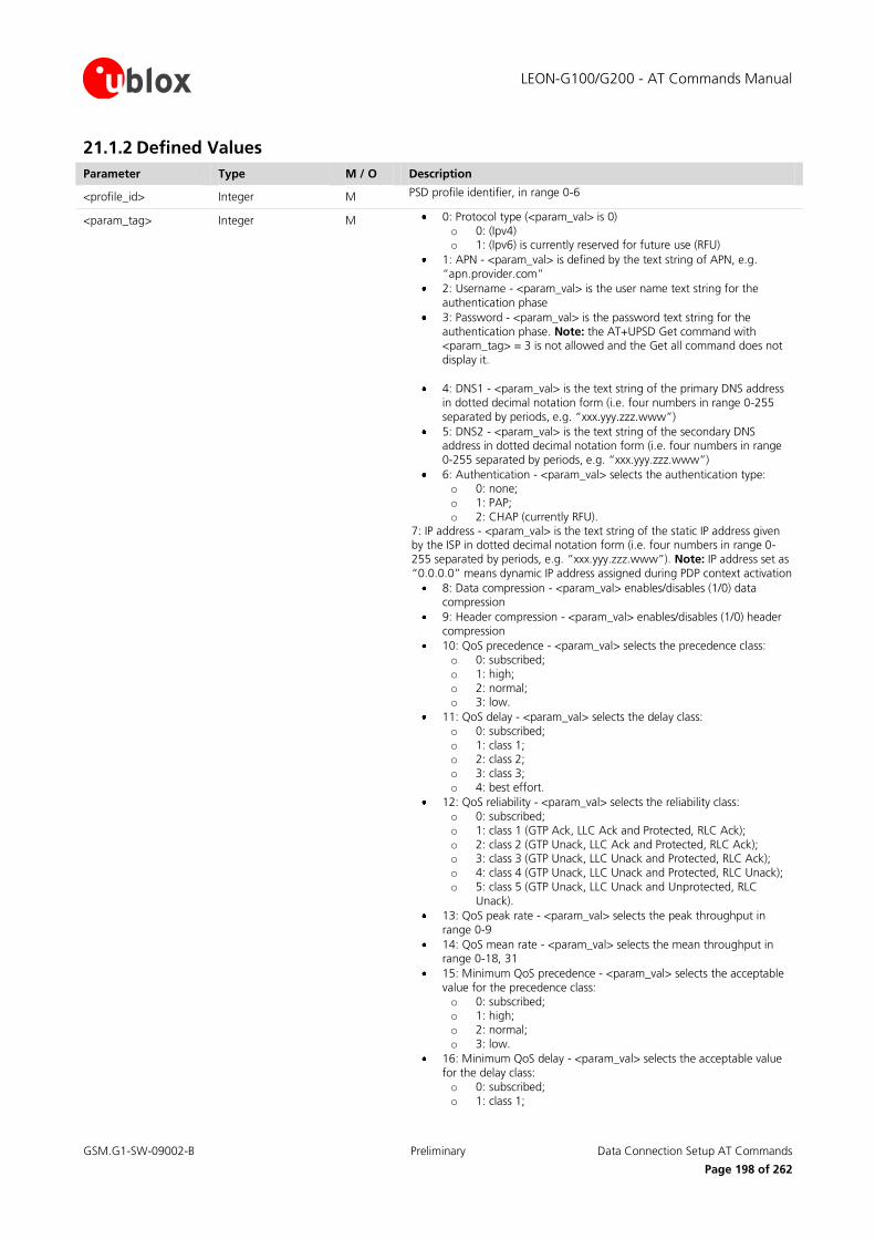
LEON-G100/G200 - AT Commands Manual
GSM.G1-SW-09002-B Preliminary Data Connection Setup AT Commands
Page 198 of 262
21.1.2 Defined Values
Parameter Type M / O Description
<profile_id> Integer M PSD profile identifier, in range 0-6
<param_tag>
Integer M 0: Protocol type (<param_val> is 0) o 0: (Ipv4) o 1: (Ipv6) is currently reserved for future use (RFU)
1: APN - <param_val> is defined by the text string of APN, e.g. “apn.provider.com”
2: Username - <param_val> is the user name text string for the authentication phase
3: Password - <param_val> is the password text string for the authentication phase. Note: the AT+UPSD Get command with <param_tag> = 3 is not allowed and the Get all command does not display it.
4: DNS1 - <param_val> is the text string of the primary DNS address in dotted decimal notation form (i.e. four numbers in range 0-255 separated by periods, e.g. “xxx.yyy.zzz.www”)
5: DNS2 - <param_val> is the text string of the secondary DNS address in dotted decimal notation form (i.e. four numbers in range 0-255 separated by periods, e.g. “xxx.yyy.zzz.www”)
6: Authentication - <param_val> selects the authentication type: o 0: none; o 1: PAP; o 2: CHAP (currently RFU).
7: IP address - <param_val> is the text string of the static IP address given by the ISP in dotted decimal notation form (i.e. four numbers in range 0-255 separated by periods, e.g. “xxx.yyy.zzz.www”). Note: IP address set as “0.0.0.0” means dynamic IP address assigned during PDP context activation
8: Data compression - <param_val> enables/disables (1/0) data compression
9: Header compression - <param_val> enables/disables (1/0) header compression
10: QoS precedence - <param_val> selects the precedence class: o 0: subscribed; o 1: high; o 2: normal; o 3: low.
11: QoS delay - <param_val> selects the delay class: o 0: subscribed; o 1: class 1; o 2: class 2; o 3: class 3; o 4: best effort.
12: QoS reliability - <param_val> selects the reliability class: o 0: subscribed; o 1: class 1 (GTP Ack, LLC Ack and Protected, RLC Ack); o 2: class 2 (GTP Unack, LLC Ack and Protected, RLC Ack); o 3: class 3 (GTP Unack, LLC Unack and Protected, RLC Ack); o 4: class 4 (GTP Unack, LLC Unack and Protected, RLC Unack); o 5: class 5 (GTP Unack, LLC Unack and Unprotected, RLC
Unack).
13: QoS peak rate - <param_val> selects the peak throughput in range 0-9
14: QoS mean rate - <param_val> selects the mean throughput in range 0-18, 31
15: Minimum QoS precedence - <param_val> selects the acceptable value for the precedence class: o 0: subscribed; o 1: high; o 2: normal; o 3: low.
16: Minimum QoS delay - <param_val> selects the acceptable value for the delay class: o 0: subscribed; o 1: class 1;

LEON-G100/G200 - AT Commands Manual
GSM.G1-SW-09002-B Preliminary Data Connection Setup AT Commands
Page 199 of 262
Parameter Type M / O Description
o 2: class 2; o 3: class 3; o 4: best effort.
17: Minimum QoS reliability - <param_val> selects the minimum acceptable value for the reliability class: o 0: subscribed; o 1: class 1 (GTP Ack, LLC Ack and Protected, RLC Ack); o 2: class 2 (GTP Unack, LLC Ack and Protected, RLC Ack); o 3: class 3 (GTP Unack, LLC Unack and Protected, RLC Ack); o 4: class 4 (GTP Unack, LLC Unack and Protected, RLC Unack); o 5: class 5 (GTP Unack, LLC Unack and Unprotected, RLC
Unack).
18: Minimum QoS peak rate - <param_val> selects the acceptable value for the peak throughput in range 0-9
19: Minimum QoS mean rate - <param_val> selects the acceptable value for the mean throughput in range 0-18, 31.
Note:
For the description of the QoS parameters, see 3GPP TS 02.60 and 3GPP TS 03.60.
21.2 Packet Switched Data Action +UPSDA
21.2.1 Description
Performs the requested action for the specified GPRS packet switched data profile.
Type Syntax Response Example
Set AT+UPSDA=<profile_id>, <action> OK AT+UPSDA=2,1
OK
21.2.2 Defined Values
Parameter Type M / O Description
<profile_id> Integer M GPRS profile identifier, in range 0-6
<action>
Integer M 0: Reset: clears the specified profile resetting all parameters to their default values;
1: Store: saves all parameters in NVM;
2: Load: reads all parameters from NVM;
3: Activate: activates a PDP context with the specified profile, using the current parameters;
4: Deactivate: deactivates the PDP context associated with the specified profile.
Note:
Only one profile can be activated at the same time. PDP context activation on more than one profile at the
same time is not supported.
In case of remote deactivation of the PDP context associated with a GPRS profile, the URC +UUPSDD: <profile_id> is sent to the TE to inform the user, otherwise the user should deactivate the PDP context
after usage.

LEON-G100/G200 - AT Commands Manual
GSM.G1-SW-09002-B Preliminary Data Connection Setup AT Commands
Page 200 of 262
21.3 Packet Switched Network-assigned Data +UPSND
21.3.1 Description
Returns the current (dynamic) network-assigned or network-negotiated value of the specified parameter for the active GPRS PDP context associated with the specified GPRS profile.
Type Syntax Response Example
Set AT+UPSND=<profile_id>,<param_tag> +UPSND: <profile_id>,<param_tag>,<dynamic_param_val>
OK
AT+UPSND=2,0
+UPSND: 2,0,”151.9.78.170”
OK
21.3.2 Defined Values
Parameter Type M / O Description
<profile_id> Integer M GPRS profile identifier, in range 0-6
<param_tag>
Integer M 0: IP address: dynamic IP address assigned during PDP context activation;
1: DNS1: dynamic primary DNS address;
2: DNS2: dynamic secondary DNS address;
3: QoS precedence: network assigned precedence class of the QoS;
4: QoS delay: network assigned delay class of the QoS;
5: QoS reliability: network assigned reliability class of the QoS;
6: QoS peak rate: network assigned peak rate value of the QoS;
7: QoS mean rate: network assigned mean rate value of the QoS.
<dynamic_param_val> value of the specified <param_tag>
21.4 Circuit Switched Data +UCSD
21.4.1 Description
Sets or gets the value of the specified parameter in a specific GSM circuit switched data (CSD) profile, or reads
the current values of all parameters of the given GPRS profile, listing them in separated lines.
The parameter values set with this command are volatile, but the whole profile may be stored in NVM with the AT+UCSDA command.
Type Syntax Response Example
Set CSD Set command
AT+UCSD=<profile_id>,<param_tag>,<param_val>
CSD Get command
AT+UCSD=<profile_id>,<param_tag>
CSD Get All command
AT+UCSD=<profile_id>
OK
+UCSD: <profile_id>, <param_tag>, <param_val>
OK
+UCSD: <profile_id>,0,<param_val0>
……..
OK
AT+UCSD=2,1,0
OK
AT+UCSD=2,1
+UCSD: 2,1,0
OK

LEON-G100/G200 - AT Commands Manual
GSM.G1-SW-09002-B Preliminary Data Connection Setup AT Commands
Page 201 of 262
21.4.2 Defined Values
Parameter Type M / O Description
<profile_id> Integer M CSD profile identifier, in range 0-6
<param_tag>
Integer M 0: Phone number - <param_val> is defined by a text string, such as “36912345678”.
1: Call type - <param_val> may be: o 0: Analog; o 1: ISDN.
2: Username - <param_val> is the user name text string for the authentication phase.
3: Password - <param_val> is the password text string for the authentication phase. Note: the AT+UCSD Get command with <param_tag> = 3 is not allowed
4: DNS1 - <param_val> is the text string of the primary DNS address in dotted decimal notation form (i.e. four numbers in range 0-255 separated by periods, like “xxx.yyy.zzz.www”).
5: DNS2 - <param_val> is the text string of the secondary DNS address in dotted decimal notation form (i.e. four numbers in range 0-255 separated by periods, like “xxx.yyy.zzz.www”).
6: Timeout (RFU) - <param_val> represents the linger time: if there is no data transfer for the given time-out, the call is hang-up). Note: currently not implemented. Parameter 6 can be neither set nor retrieved
21.5 Circuit Switched Data Action +UCSDA
21.5.1 Description
Performs the requested action for the specified CSD profile.
Type Syntax Response Example
Set AT+UCSDA=<profile_id>, <action> OK AT+UCSDA=3,0
21.5.2 Defined Values
Parameter Type M / O Description
<profile_id> Integer M CSD profile identifier, in range 0-6
<action>
Integer M 0: Reset: clears the specified profile, resetting all parameters to their default values
1: Store: saves all parameters of the specified profile in NVM for future retrieval
2: Load: reads all parameters of the specified profile from NVM
3: Activate: performs end-to-end connection establishment for the specified CSD profile, using its pre-defined parameters (i.e. service provider number)
4: Deactivate: releases the GSM data call associated with the specified CSD profile
Note:
1) only one profile at a time can be associated with an active GSM call.
2) in case of remote disconnection of a GSM call associated to a CSD profile, the URC +UUCSDD: <profile_id> is sent to the TE to inform the user, otherwise the user is in charge of connection release after usage.

LEON-G100/G200 - AT Commands Manual
GSM.G1-SW-09002-B Preliminary Data Connection Setup AT Commands
Page 202 of 262
21.6 Circuit Switched Network-assigned Data +UCSND
21.6.1 Description
Returns the current (dynamic) network-assigned value of the specified parameter of the active GSM data call associated with the specified CSD profile.
Type Syntax Response Example
Set AT+UCSND=<profile_id>, <param_tag> +UCSND: <profile_id>,<param_tag>, <dynamic_param_val>
OK
AT+UCSND=2,0
+UCSND: 2,0,”151.9.78.170”
OK
21.6.2 Defined Values
Parameter Type M / O Description
<profile_id> Integer M CSD profile identifier, in range 0-6
<param_tag>
Integer M 0: IP address: dynamic IP address assigned during context activation
1: DNS1: dynamic primary DNS address
2: DNS2: dynamic secondary DNS address
<dynamic_param_val> value of the specified <param_tag>

LEON-G100/G200 - AT Commands Manual
GSM.G1-SW-09002-B Preliminary DNS AT Commands
Page 203 of 262
22 DNS AT Commands To utilize the DNS service the user must first define and activate a connection profile, either PSD or CSD, using
the specific AT commands described in chapter “Data Connection Setup AT Commands”.
22.1 Resolve Name / IP Number through DNS +UDNSRN
22.1.1 Description
Translates a domain name to an IP address or an IP address to a domain name by using an available DNS. There
are two available DNSs, primary and secondary. They are usually provided by the network after GPRS activation
or CSD establishment. They are automatically used in the resolution process if available. The resolutor will use first the primary DNS, if no answer, the second DNS will be involved. User can replace each network provided
DNS by setting its own DNS. In this case the command AT+UPSND should be used for a PSD context or the
AT+UCSD command for the CSD context. If a DNS value different from “0.0.0.0” is provided, the user DNS will replace the correspondent network-provided one. Pay attention to the DNS setting for the different profiles since
the user DNS can be put into action if the corresponding profile is activated (if the user sets a DNS for a profile,
and a different profile is activated, the user DNS has no action and the network DNS is used if available).
Usage of the network provided DNSs is recommended.
Type Syntax Response Example
Set AT+UDNSRN=<resolution_type>,<domain_ip_string>
+UDNSRN: <resolved_ip_address>
OK
or
+UDNSRN: <resolved_domain_name>
OK
AT+UDNSRN=0,www.google.com
OK
+UDNSRN: “216.239.59.147”
OK
22.1.2 Defined Values
Parameter Type M / O Description
<resolution_type >
Integer M type of resolution operation
0: domain name to IP address
1: IP address to domain name (host by name)
<domain_ip_string> String M domain name (resolution_type=0) or the IP address in (resolution_type=1) to be resolved
<resolved_ip_address> String resolved IP address corresponding to the specified domain name
<resolved_domain_name> String resolved domain name corresponding to the provided IP address

LEON-G100/G200 - AT Commands Manual
GSM.G1-SW-09002-B Preliminary TCP/IP UDP/IP AT Commands
Page 204 of 262
23 TCP/IP UDP/IP AT Commands
23.1 Introduction
Before using TCP/IP services, a connection profile (either PSD or CSD) must be defined and activated, with AT
commands described in chapter 21 “Data Connection Setup AT Commands”. Up to 16 sockets can be managed
independently and simultaneously over the same bearer (either GPRS or GSM). AT commands for both reading and writing data on sockets are provided and URC notifies the external application of incoming data and
transmission result, no need for polling.
Some network operators close dynamic NATs after few minutes if there is no activity on the connection (no data trasfer in the period). To solve this problem enable the TCP keep alive
options with 1 minute delay (view +USOSO command, paragraph 23.3).
23.2 Create Socket +USOCR
23.2.1 Description
Creates a socket and associates it with the specified protocol (TCP or UDP), returns an integer identifying the
socket. Such command corresponds to the BSD socket routine. Up to 16 sockets can be created.
Type Syntax Response Example
Set AT+USOCR=<protocol> +USOCR: <socket>
OK
+USOCR: 2
OK
23.2.2 Defined Values
Parameter Type M / O Description
<protocol> Integer M 6: TCP
17: UDP
<socket> Integer M socket identifier to be used for any future operation on that socket; the range goes from 0 to 15
23.3 Set Socket Option +USOSO
23.3.1 Description
Sets the specified standard option (type of service, local address re-use, linger time, time-to-live, etc) for the specified socket, like the BSD setsockopt routine.
Note: Parameters must be set one by one.
Type Syntax Response Example
Set AT+USOSO=<socket>,<level>,<opt_name>,<opt_val> [, <opt_val2>]
OK AT+USOSO=2,6,1,1
OK

LEON-G100/G200 - AT Commands Manual
GSM.G1-SW-09002-B Preliminary TCP/IP UDP/IP AT Commands
Page 205 of 262
23.3.2 Defined Values
Parameter Type M / O Description
<socket> Integer M socket identifier, in range 0-15
<level>
Integer M 0: IP Protocol
<opt_name> for IP Protocol level may be:
1: Type of service <opt_val>: 8 bit mask that represent the flags of IP TOS. For more information refer to RFC 791 [27]Range 0-255. Default value is 0
2: Time-to-live <opt_val>: unsigned 8 bit value representing the TTL. Range 0-255 (default 255)
6: TCP Protocol <opt_name> for TCP protocol level may be:
1: No delay option: don’t delay send to coalesce packets; <opt_val>: integer, enables/disables “no delay” option. 1: enable, 0: disable (default)
2: Keepalive option: send keepalive probes when idle for <opt_val> milliseconds; <opt_val>: signed 32 bit integer value representing the milliseconds for “keepalive” option. Range 0-2147483647. Default value 7200000 (2 hours).
65535: Socket <opt_name> for Socket level options may be:
4: Local address re-use. <opt_val>: integer, enables/disables “local address re-use” option. 1: enable, 0: disable (default 0)
8: Keep connections alive. <opt_val>: integer, enables/disables “keep connections alive” optio. 1: enable, 0: disable (default 0)
32: Sending of broadcast messages. <opt_val>: integer enables/disables “sending of broadcast messages”. 1: enable, 0: disable (default 0)
128: Linger on close if data present. <opt_val>: integer, sets on/off “linger” option. 1: enable, 0: disable (default 0) <opt_val2>: signed 16 bit integer, linger time, range 0-32767. Default is 0.
512: Local address and port re-use. <opt_val>: integer, enables/disables “local address and port re-use”. 1: enable, 0: disable (default 0)
23.4 Get Socket Option +USOGO
23.4.1 Description
Retrieves the specified standard option (type of service, local address re-use, linger time, time-to-live, etc) for the
specified socket, like the BSD getsockopt routine.
Type Syntax Response Example
Set AT+USOGO=<socket>, <level>,<opt_name>
+USOGO: <opt_val>[,<opt_val2>]
OK
+USOGO: 1
OK

LEON-G100/G200 - AT Commands Manual
GSM.G1-SW-09002-B Preliminary TCP/IP UDP/IP AT Commands
Page 206 of 262
23.4.2 Defined Values
Parameter Type M / O Description
<socket> Integer M socket identifier, in range 0-15
<level>
Integer M 0: IP Protocol <opt_name> for IP Protocol level can be: o 1: Type of service. o 2: Time-to-live.
6: TCP Protocol <opt_name> for TCP protocol level may be:
o 1: No delay option: don’t delay send to coalesce packets. o 2: Keepalive option: send keepalive probes when idle for
<opt_val> milliseconds.
65535: Socket <opt_name> for Socket level options may be:
o 4: Local address re-use. o 8: Keep connections alive. o 32: Sending of broadcast messages. o 128: Linger on close if data present; <opt_val2>: integer,
linger time; o 512: Local address and port re-use.
Note:
Forthe values returned by the +USOGO command, refer to the +USOSO command description (paragraph 23.3).
23.5 Close Socket +USOCL
23.5.1 Description
Closes the specified socket, like the BSD close routine. In case of remote socket closure the user is notified via the URC +UUSOCL: <socket>.
Type Syntax Response Example
Set AT+USOCL=<socket> OK AT+USOCL=2
OK
URC +UUSOCL: <socket> +UUSOCL: 2
23.6 Get Socket Error +USOER
23.6.1 Description
Retrieves the last error occurred in the last socket operation, stored in the BSD standard variable error.
Type Syntax Response Example
Action AT+USOER +USOER: <socket_error>
OK
+USOER: 104
OK
23.6.2 Defined Values
Parameter Tye M / O Description
<socket_error> Integer M code of the last error occurred in a socket operation. 0: no error

LEON-G100/G200 - AT Commands Manual
GSM.G1-SW-09002-B Preliminary TCP/IP UDP/IP AT Commands
Page 207 of 262
23.7 Connect Socket +USOCO
23.7.1 Description
Establishes a peer-to-peer connection of the socket to the specified remote host on the given remote port, like the BSD connect routine. If the socket is a TCP socket, the command will actually perform the TCP negotiation
(3-way handshake) to open a connection. If the socket is an UDP socket, this function will just declare the
remote host address and port for later use with other socket operations (e.g. +USOWR, +USORD). This is important to note because if <socket> refers to an UDP socket, errors will not be reported prior to an attempt to
write or read data on the socket. The logical usage of the Connect procedure and UDP active sockets is
described in [1].
Type Syntax Response Example
Set AT+USOCO=<socket>, <remote_addr>, <remote_port>
OK AT+USOCO=3,”151.63.16.9”,1200
OK
23.7.2 Defined Values
Parameter Type M / O Description
<socket> Integer M socket identifier, in range 0-15
<remote_addr> String M remote host IP address in dotted decimal notation form (i.e. four numbers in range 0-255 separated by periods).
<remote_port> Interger M remote host port, in range 1-65535.
23.8 Write Socket Data +USOWR
23.8.1 Description
Writes the specified amount of data to the specified socket, like the BSD write routine, and returns the number
of bytes of data actually written. Applied to UDP sockets too, after a +USOCO Connect Socket command.
There are two kinds of syntax:
Base syntax: for writing simple strings to the socket with the limitation that there are characters which are
forbidden;
Binary extended syntax: mandatory for writing any character in the ASCII range [0x00, 0xFF]
Type Syntax Response Example
Set
(Base)
AT+USOWR=<socket>, <length>,<data>
+USOWR: <socket>,<length>
OK
+USOWR: 3,16
OK
Set
(Binary)
AT+USOWR=<socket>, <length>
After the”@” prompt <length> bytes of data are entered
@
+USOWR: <socket>,<length>
OK
@16 bytes of data
+USOWR: 3,16
OK

LEON-G100/G200 - AT Commands Manual
GSM.G1-SW-09002-B Preliminary TCP/IP UDP/IP AT Commands
Page 208 of 262
23.8.2 Defined Values
Parameter Type M / O Description
<socket> Integer M socket identifier, in range 0-15
<length> Integer M number of data bytes to write, in range 0-512
<data> Interger M data bytes to be written
Note:
For Base Sytntax: Allowed ASCII chars are:
0x20 (space), 0x21and from 0x23 to 0xFF, all the alphanumeric set, symbols and extended ASCII charset from 0x80 to 0xFF.
Forbidden: The control chars from 0x00 to 0x1F (included), 0x22 char, quotation marks (“)
The value of <length> and the actual length of <data> must match.
For Binary Sytntax
After the command is sent, the user waits for the @ prompt. When it appears the stream of bytes can be
provided. After the specified amount of bytes has been sent, the system returns with OK (or ERROR). The feed process cannot be interrupted i.e. the return in the command mode can be effective only when the
number of bytes provided is the declared one.
That Binary extended syntax is the only way for the system to accept control chars as data; for the AT command specifications [16], chars like <CR>, <CTRL-Z>, quotation marks, etc. have a specific meaning and
they cannot be used like data in the command itself. The command is so extended with a specific
acceptance state identified by the @ prompt.
This feature can be successfully used when there is need to send a byte stream which belongs to a protocol
that has any kind of chars in the ASCII range [0x00,0xFF].
23.9 Read Socket Data +USORD
23.9.1 Description
Reads the specified amount of data from the specified socket, like the BSD read routine. The URC +UUSORD: <socket>,<length> notifies that new data is available for reading, either when new data arrives or after a
partial read by the user for the TCP socket type. This command can also return the total amount of unread data.
This command can be applied to UDP active sockets too with the following exceptions:
Note that the UDP is a connectionless protocol i.e. in an UDP active connection, data can be received only
after an UDP packet is sent to a remote server: in this case the remote server replies to the local port and the
local stack gets the response. This means that a Read Socket operation will always follow a Write Socket operation. If Write Socket operation (after a Connect operation) is not performed, data cannot be received
by the IP stack (and the remote peer will receive an ICMP error type 3 code 3, destination port unreachable);
Furthermore data reading from an UDP socket should be done in ‘one shot’ only: if a read attempt specifies less bytes than the value reported in the URC, the number of the bytes specified are returned but there is
not possible to read the remained part of the UDP datagram incame. This kind of behaviour is in
conformance with UDP socket architecture described in [1].
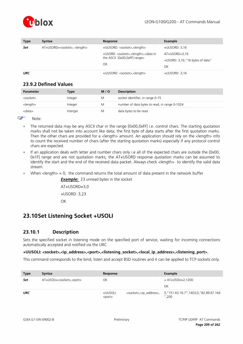
LEON-G100/G200 - AT Commands Manual
GSM.G1-SW-09002-B Preliminary TCP/IP UDP/IP AT Commands
Page 209 of 262
Type Syntax Response Example
Set AT+USORD=<socket>, <length> +UUSORD: <socket>,<length>
+USORD: <socket>,<length>,<data in the ASCII [0x00,0xFF] range>
OK
+UUSORD: 3,16
AT+USORD=3,16
+USORD: 3,16,”16 bytes of data”
OK
URC +UUSORD: <socket>,<length> +UUSORD: 3,16
23.9.2 Defined Values
Parameter Type M / O Description
<socket> Integer M socket identifier, in range 0-15
<length> Integer M number of data bytes to read, in range 0-1024
<data> Interger M data bytes to be read
Note:
The returned data may be any ASCII char in the range [0x00,0xFF] i.e. control chars. The starting quotation marks shall not be taken into account like data; the first byte of data starts after the first quotation marks.
Then the other chars are provided for a <length> amount. An application should rely on the <length> info
to count the received number of chars (after the starting quotation marks) especially if any protocol control chars are expected.
If an application deals with letter and number chars only i.e all of the expected chars are outside the [0x00,
0x1F] range and are not quotation marks, the AT+USORD response quotation marks can be assumed to identify the start and the end of the received data packet. Always check <length> to identify the valid data
stream.
When <length> = 0, the command returns the total amount of data present in the network buffer
Example: 23 unread bytes in the socket
AT+USORD=3,0
+USORD: 3,23
OK
23.10 Set Listening Socket +USOLI
23.10.1 Description
Sets the specified socket in listening mode on the specified port of service, waiting for incoming connections
automatically accepted and notified via the URC
+UUSOLI: <socket>,<ip_address>,<port>,<listening_socket>,<local_ip_address>,<listening_port>,
This command corresponds to the bind, listen and accept BSD routines and it can be applied to TCP sockets only.
Type Syntax Response Example
Set AT+USOLI=<socket>,<port> OK
+ AT+USOLI=2,1200
OK
URC +UUSOLI: <socket>,<ip_address>, <port>
3,”151.63.16.7”,1403,0,”82.89.67.164”,200

LEON-G100/G200 - AT Commands Manual
GSM.G1-SW-09002-B Preliminary TCP/IP UDP/IP AT Commands
Page 210 of 262
23.10.2 Defined Values
Parameter Type M / O Description
<socket> Integer M socket identifier, in range 0-15
<port> Integer M port of service, range 1-65535. Port numbers below 1024 are not recommended since they are usually reserved
<ip_address> String M remote host IP address (only in URC +UUSOLI)
<listening_socket> Integer socket identifier specified within the AT+USOLI command, indicates on which listening socket the connection has been accepted (only in +UUSOLI URC)
<local_ip_address> String TE IP address (only in +UUSOLI URC)
<listening_port> Integer listening port that has accepted the connection. This port is specified within the AT+USOLI command (only in +UUSOLI URC)
Note:
in case of notification via the URC +UUSOLI <port> is intended as the remote port
23.11 Firewall control +UFRW
23.11.1 Description
Enables/disables internal firewall and controls filtering settings (i.e. define IP white list). When enabled, IP
connections are accepted only if the IP address belongs to the defined IP white list.
Note:
the firewall applies for incoming connections only (i.e. listening sockets set by means of +USOLI command).
Type Syntax Response Example
Set AT+UFRW=<action>[,<white_ip_addr_mask>]
OK
AT+UFRW=0
OK
Read AT+UFRW? +UFRW: <firewall_status> [,<white_ip_addr_mask1>[, <white_ip_addr_mask2> [,...]]]
OK
Test AT+UFRW=? +UFRW: (list of supported <action>s)
OK
+UFRW: (0-4)
OK

LEON-G100/G200 - AT Commands Manual
GSM.G1-SW-09002-B Preliminary TCP/IP UDP/IP AT Commands
Page 211 of 262
23.11.2 Defined Values
Parameter Type M / O Description
<action>
Integer M 0: disable internal firewall. The parameter <white_ip_addr_mask> is not allowed in this case: if present error message will be returned
1: enable internal firewall. The parameter <white_ip_addr_mask> is not allowed in this case: if present error message will be returned
2: add specified IP address mask to firewall white list. The parameter <white_ip_addr_mask> is mandatory. The maximum size of firewall white list is 10 IP address masks: up to 10 different IP address masks can be added to firewall white list.
3: remove specified IP address mask from firewall white list. The parameter <white_ip_addr_mask> is mandatory
4: clear firewall white list. The parameter <white_ip_addr_mask> is not allowed in this case: if present error message will be returned
<white_ip_addr_mask>
String white IP address mask to be applied to remote end IP address to decide if to accept or not the remote connection. The IP address mask is made up of 4 bytes of information expressed as four numbers in range 0-255 separated by periods (e.g. “xxx.yyy.zzz.www”). An incoming connection attempt from the remote end IP address <incoming_ip_addr> is accepted if matching the following criterium for at least one of the IP address masks in the firewall white list: <incoming_ip_addr> & <white_ip_addr_mask> == <incoming_ip_addr>
<firewall_status> Integer M 0: disabled
1: enabled

LEON-G100/G200 - AT Commands Manual
GSM.G1-SW-09002-B Preliminary FTP AT Commands
Page 212 of 262
24 FTP AT Commands Proprietary u-blox AT commands. PSD or CSD connection must be established before using FTD client services
(AT commands for establishing connection are described in chapter “Data Connection Setup AT Commands”) . AT commands enable sending and receiving files over the available bearer transparently, retrieving and storing
them in the file system. Standard file and directory management operations on the remote side are possible.
In general, two AT-commands are defined for a FTP service: one command to set the profile, second command to execute a specific FTP command. The result of a FTP execute command will be notified through the URC
+UUFTPCR. Data is provided through URC +UUFTPCD.
24.1 File Transfer Protocol Control +UFTP
24.1.1 Description
Sets up a parameter for FTP service, or resets a parameter to its default value. Set command needs to be executed for each single <param_tag>. Read command returns the current setting of all the FTP parameters, one
per line (i.e. the FTP profile). The FTP parameter values set with this command are all volatile (not stored in non-
volatile memory)
Type Syntax Response Example
Set Set command
AT+UFTP=<param_tag>, <param_val>
Reset command
AT+UFTP=<param_tag>
OK
OK
AT+UFRW=0
OK
Read AT+UFTP? +UFTP: 0,<param_val0>
+UFTP: 1,<param_val1>
.....
OK
+UFTP: 0,”216.239.59.147”
+UFTP: 1,””
+UFTP: 2,”username”
+UFTP: 4,”account”
+UFTP: 5,0
+UFTP: 6,0
OK
Test AT+UFTP=? +UFTP: (list of supported <param_tag>s)
OK
+UFTP: (0-6)
OK

LEON-G100/G200 - AT Commands Manual
GSM.G1-SW-09002-B Preliminary FTP AT Commands
Page 213 of 262
24.1.2 Defined Values
Parameter Type M / O Description
<param_val>
Integer O type and supported content depend on related <param_tag> (details are given here below). If <param_val> is not specified the value of the corresponding parameter <param_tag> is reset
<param_tag>
Integer 0: FTP server IP address; <param_val> is the text string of FTP server IP address in dotted decimal notation form (e.g. 1111.2222.3333.4444)
1: FTP server name <param_val> is the text sting of FTP server name (e.g. “ftp.server.com”) Maximal length 128 chars
2: Username <param_val> is the user name text string (maximum 30 chars) for the FTP login procedure
3: Password <param_val> is the password text string (maximum 30 chars) for the FTP login procedure
4: Account <param_val> is the additional user account text string (maximum 30 chars) if required for the FTP login procedure
5: Inactivity timeout; <param_val> is the inactivity timeout period in seconds, from 0 to 86400 seconds. 0 (default) means no timeout (the FTP session will not be terminated in the absence of incoming traffic)
6: FTP mode <param_val> selects the FTP mode: o 0: Active (default) o 1: Passive
Note:
Notice that <param_tag>=0 and <param_tag>=1 are mutually exclusive. If value for <param_tag>=0 is
specified by user, then value for <param_tag>=1 is reset or vice versa.
FTP port number is fixed to 21 cannot be changed).
24.2 File Transfer Protocol Command +UFTPC
24.2.1 Description
Triggers the FTP action corresponding to <ftp_command> parameter. The response indicates if sending the
command request to FTP process was successful or not. Final result of FTP action will be returned to the user via the URC +UUFTPCR (please refer to paragraph 24.4). As well, when data is requested by user (e.g. file or
directory lists), the information is notified after reception from the FTP server via URC +UUFTPCD (please refer to
paragraph 24.3).
Type Syntax Response Example
Set AT+UFTPC=<ftp_command> [,<param1>[,<param2>]]
OK
AT+UFTPC=4,”data.zip”,”data.zip”
OK
Test AT+UFTPC=? +UFTPC: (list of supported <ftp_command>s)
OK
+UFTPC: (0-5,8,10,11,13,14)
OK

LEON-G100/G200 - AT Commands Manual
GSM.G1-SW-09002-B Preliminary FTP AT Commands
Page 214 of 262
24.2.2 Defined Values
Parameter Type M / O Description
<param1> Integer O type and content depend on related <ftp_command> (details are given below)
<param2> Integer O type and content depend on related <ftp_command> (details are given below)
<ftp_command>
Integer 0: FTP logout; terminates the FTP session by performing a logout. Notice that this AT command just sends a command request to the FTP process. The final FTP result will be notified via the URC +UUFTPCR (please refer to paragraph 24.4). o <param1>, <param2> are not allowed (do not give any
value).
1: FTP login; connects to the FTP server using the parameters of current FTP profile (set via AT+UFTP command). Notice that this AT command just sends a command request to the FTP process. The final FTP result will be notified via the URC +UUFTPCR (please refer to paragraph 24.4). o <param1> param2> are not allowed (do not give any
value).
2: Delete file from the FTP server. This AT command just sends a command request to the FTP process. The final FTP result will be notified via the URC +UUFTPCR (see 24.4). o <param1> mandatory parameter; text string of the file
name to be deleted from FTP host. o <param2> parameter is not allowed (do not give any
value).
3: Rename file. This AT command just sends requests to the FTP process. The final FTP result will be notified via the URC +UUFTPCR (see 2.1). o <param1> mandatory parameter; text string of the old file
name text string on the FTP host, to be renamed. For the limit of the length of the string please refer to 2.1.
o <param2> mandatory parameter; text string of the new file name. For the limit of the length of the string please refer to 2.1.
4: Retrieve file from the FTP server. This command just sends a command request to the FTP process. The final FTP command result is notified via the URC +UUFTPCR (see 2.1). o <param1> mandatory parameter; is the remote file name
text string to be retrieved from FTP host. o <param2> mandatory parameter; is the local file name
(LEON file system) text string to be stored on file system. For the limit of the length of the string please refer to 2.1.
5: Store file on the FTP server. This AT command just sends a command request to the FTP process. The final result will be notified via the URC +UUFTPCR (please refer to paragraph 24.4). o <param1> mandatory parameter; is the local file name
(LEON file system) text string to be sent from file system. For the limit of the length of the string please refer to 2.1.
o <param2> mandatory parameter; is the remote file name to be stored on the FTP server. For the limit of the length of the string please refer to 2.1.
6: RFU;
7: RFU;
8: Change working directory to the specified one. This AT command just sends requests to the FTP process. The final FTP command result will be notified via the URC +UUFTPCR (please refer to paragraph 24.4). o <param1> mandatory parameter; is the text string of the
destination directory name on the FTP host. For the limit of the length of the string please refer to 2.1.
o <param2> parameter is not allowed (do not give a value).
9: RFU;
10: Create a directory on the FTP host. This AT command just sends a command request to the FTP process. The final result will

LEON-G100/G200 - AT Commands Manual
GSM.G1-SW-09002-B Preliminary FTP AT Commands
Page 215 of 262
Parameter Type M / O Description
be notified via the URC +UUFTPCR (please refer to paragraph 24.4). o <param1> mandatory parameter; text string of the new
directory name to be made on FTP server. For the limit of the length of the string please refer to 2.1.
o <param2> parameter is not allowed (do not give a value).
11: Remove directory from the remote FTP server. This AT command just sends a command request to the FTP process. The final result will be notified via the URC +UUFTPCR (please refer to paragraph 24.4). o <param1> mandatory parameter; is the string of the
existing directory name to be removed. For the limit of the length of the string please refer to 2.1.
o <param2> parameter is not allowed (do not give a value).
12: RFU;
13: Information of a file or a directory. Command just sends a command request to the FTP process. Information of specified file or directory from FTP server will be returned via URC +UUFTPCD (please refer to paragraph 24.3). The final FTP command result will be notified via the URC +UUFTPCR (please refer to paragraph 24.4). o <param1> optional parameter; text string of the path
file/directory name to be listed. If not specified, the current directory list is requested. For the limit of the length of the string please refer to 2.1.
o <param2> parameter is not allowed (do not give a value).
14: List file names in a specified directory. Command just sends a command request to the FTP process. List of file names received from FTP server will be returned via URC +UUFTPCD (please refer to paragraph 24.3). The final FTP result will be notified via the URC +UUFTPCR (please refer to paragraph 24.4). o <param1> optional parameter; text string of the path (file
or directory) to be name listed. If not specified, the list of files names of current working directory is requested. For the limit of the length of the string please refer to 2.1.
o <param2> parameter is not allowed (do not give a value).
24.3 FTP Unsolicited Data Indication +UUFTPCD
24.3.1 Description
Returns the data received from the remote FTP server in response to a specified <ftp_command> request
previously sent via AT+UFTPC command.
Type Syntax Response Example
URC +UUFTPCD: <ftp_command>,<ftp_data_len>,<ftp_data>
+UUFTPCD: 13,16,“16 bytes of data”
24.3.2 Defined Values
Parameter Type M / O Description
<ftp_command> Integer M FTP command as detailed in Defined Values paragraph 24.2.2 “File Transfer Protocol Command +UFTPC”.
<ftp_data_len> Integer M amount of data in bytes
<ftp_data> String data available from FTP server in the ASCII [0x00,0xFF] range. The starting quotation mark shall not be taken into account like data, the first byte of data starts after the first quotation mark. Total number of

LEON-G100/G200 - AT Commands Manual
GSM.G1-SW-09002-B Preliminary FTP AT Commands
Page 216 of 262
Parameter Type M / O Description
bytes is <ftp_data_len>. At the end of the byte stream, another quotation mark is provided for user convenience and visualization purposes.
24.4 FTP Unsolicited Result Indication +UUFTPCR
24.4.1 Description
The result of the operation for a FTP command previously sent with +UFTPC is provided with this URC.
Type Syntax Response Example
URC +UUFTPCR: <ftp_command>,<ftp_result>
+UUFTPCR: 1,1
24.4.2 Defined Values
Parameter Type M / O Description
<ftp_command> Integer O Same values as above
<ftp_result> Integer 0: Fail
1: Success
24.5 File Transfer Protocol Error +UFTPER
24.5.1 Description
This command retrieves the error class and code of the last FTP operation.
Type Syntax Response Example
Action AT+UFTPER +UFTPER: <error_class>,<error_code>
OK
+UUFTPCR: 1,1
24.5.2 Defined Values
Parameter Type M / O Description
<error_class>
Integer O Value of error class. Values are listed in paragraph A.1
<error_code> Integer Value of class-specific error code (reply code if <error_class> is 0)

LEON-G100/G200 - AT Commands Manual
GSM.G1-SW-09002-B Preliminary HTTP AT commands
Page 217 of 262
25 HTTP AT commands u-blox proprietary AT commands. Sending requests to a remote HTTP server and receiving the server response,
transparently storing it in the file system. Supported: HEAD, GET, DELETE, PUT, POST file, POST data. GPRS or GSM data connection must be activated, using the specific AT commands described in chapter 21 “Data
Connection Setup AT Commands”.
25.1 HTTP Control +UHTTP
25.1.1 Description
Sets up the necessary parameters for HTTP service, or resets them to the default values. Up to 4 different HTTP profiles can be defined. To change the settings of a specified HTTP profile: set command needs to be executed
for each single <param_tag>. The read command returns the current setting of the specified parameter of HTTP
profile, while the reset command resets to default values all the parameters of specified HTTP profile.
HTTP parameters are not saved in the non volatile memory.
Type Syntax Response Example
Set Set command
AT+UHTTP=<profile_id>[,<param_tag>[,<param_val>]]
Get command
AT+UHTTP=<profile_id>,<param_tag>
Reset command
AT+UHTTP=<profile_id>
OK
+UHTTP: <profile_id>, <param_tag>, <param_val>
OK
AT+UHTTP=2,0,”125.24.51.133”
OK
AT+UHTTP=2,0
+UHTTP: 2,0,”125.24.51.133”
OK
AT+UHTTP=2
OK
Test AT+UHTTP=? +UHTTP: (list of supported <profile_id>s),(list of supported <param_tag>s)
OK
+UHTTP: (0-3),(0-5)
OK
25.1.2 Defined Values
Parameter Type M / O Description
<profile_id> Integer M HTTP profile identifier, in range 0-3
<param_val>
Integer O type and supported content depend on related <param_tag> (details below). If <param_val> is not specified, the current parameter value for the corresponding <param_tag> is returned.
<param_tag>
O If <param_tag> and <param_val> are not specified, all the parameters of the corresponding HTTP <profile_id> are reset to default value.
0: HTTP server IP address o <param_val>: text string of HTTP server IP address in
dotted decimal notation form (i.e. four numbers in range 0-255 separated by periods)

LEON-G100/G200 - AT Commands Manual
GSM.G1-SW-09002-B Preliminary HTTP AT commands
Page 218 of 262
Parameter Type M / O Description
1: HTTP server name o <param_val>: text string of HTTP server name (e.g.
“http.server.com”) Maximum length for string is 128 chars
2: Username o <param_val>: user name text string (maximum 30 chars)
for the HTTP login procedure if authentication is used
3: Password o <param_val>: password text string (maximum 30 chars) for
the HTTP login procedure if authentication is used
4: Authentication type o <param_val> is the HTTP authentication method (if any)
0: No authentication (default)
1: Basic authentication
5: HTTP server port o <param_val> integer type value of the HTTP server port to
be used in HTTP request, in range 1-65535. Default value is 80.
<param_tag>=0 and <param_tag>=1 are mutually exclusive. If <param_val> value for <param_tag>=0 is specified by user, then value for <param_tag>=1 is reset, or vice versa.
25.2 HTTP Command +UHTTPC
25.2.1 Description
Triggers the HTTP action specified in <http_command> parameter, using the HTTP profile settings (previously set
up by AT+UHTTP command), and corresponding to <profile_id>. The response indicates if sending the command request to HTTP process was successful or not. Final result of HTTP action will be returned to the user via the
unsolicited indication +UUHTTPCR ( chapter 25.3).
Type Syntax Response Example
Set AT+UHTTPC=<profile_id>, <http_command>,<param1>,<param2>[,<param3>[,<param4>]]
OK
AT+UHTTPC=0,1,”/path/file.html”,”responseFilename”
OK
Test AT+UHTTPC=? +UHTTPC: (list of supported <profile_id>s),(list of supported <http_command>s)
OK
+UHTTPC: (0-3), (0-5)
OK
25.2.2 Defined Values
Parameter Type M / O Description
<profile_id> Integer M HTTP profile identifier, in range 0-3
<param1> String path of HTTP server resource. Maximum length 128 characters
<param2>
String filename where the HTTP server response will be stored. If the file already exists, it will be overwritten. If <param2> is the empty string (“”), the default “http_last_response_<profile_id>” filename will be used
<param3> O type and content depend on related <http_command> (details below).
<http_command>
Integer 0: HEAD command; issue an HEAD request to HTTP server. Command just sends a command request to the HTTP process. The final HTTP command result will be notified via the URC +UUHTTPCR (see detailed description) o <param3>: not allowed

LEON-G100/G200 - AT Commands Manual
GSM.G1-SW-09002-B Preliminary HTTP AT commands
Page 219 of 262
Parameter Type M / O Description
o <param4>: not allowed
1: GET command; perform a GET request to HTTP server. Command just sends a command request to the HTTP process. The final HTTP command result will be notified via the URC +UUHTTPCR (see details below) o <param3>: not allowed o <param4>: not allowed
2: DELETE command; send a DELETE request to HTTP server. Command just sends a command request to the HTTP process. The final HTTP command result will be notified via the URC +UUHTTPCR (see detailed description) o <param3>: not allowed o <param4>: not allowed
3: PUT command; perform a PUT request to HTTP server. Command just sends a command request to the HTTP process. The final HTTP command result will be notified via the URC +UUHTTPCR (see detailed description) o <param3>: mandatory parameter; text string of the file
system filename to be sent to the HTTP server within the PUT request
o <param4>: not allowed
4: POST a file command; issue a POST request for sending a file to the HTTP server. Command just sends a command request to the HTTP process. The final HTTP command result will be notified via the URC +UUHTTPCR (see detailed description). o <param3>: mandatory parameter; text string of the file
system filename to be sent to the HTTP server with the POST request
o <param4> mandatory parameter of integer type; it is the HTTP Content-Type identifier
0: application/x-www-form-urlencoded
1: text/plain
2: application/octet-stream
3: multipart/form-data
5: POST data command; send a POST request to HTTP server using the data specified in <param3> parameter. Command just sends a command request to the HTTP process. The final HTTP command result will be notified via the URC +UUHTTPCR (see detailed description). o <param3>: mandatory parameter; text string of the data to
be sent to the HTTP server with the POST request. The data must be formatted according to the Content-Type specified in <param4> parameter.
Data string must not exceed the maximum length of 128 bytes and not all of the ASCII charset can be used. Allowed ASCII characters are: 0x20 (space), 0x21 and from 0x23 to 0xFF. Substantially all of the
alphanumeric set, symbols and extended ASCII charset from 0x80 to 0xFF. The control characters from 0x00
to 0x1F (included) and the 0x22 char, quotation mark (“), are forbidden.

LEON-G100/G200 - AT Commands Manual
GSM.G1-SW-09002-B Preliminary HTTP AT commands
Page 220 of 262
25.3 HTTP Command Result Unsolicited Indication +UUHTTPCR
25.3.1 Description
This unsolicited indication returns the final result of HTTP command AT+UHTTPC.
Type Syntax Response Example
URC +UUHTTPCR: <profile_id>,<http_command>,<http_result>
+UUHTTPCR: 0,1,1
25.3.2 Defined Values
Parameter Type M / O Description
<profile_id> Integer M HTTP profile identifier, in range 0-3
<http_command> Integer Specifies values of <http_command> used in +UHTTPC”
<http_result> Integer 0: Fail
1: Success
25.4 HTTP rotocol Error +UHTTPER
25.4.1 Description
Retrieves the error class and code of the last HTTP operation on specified HTTP profile.
Type Syntax Response Example
Set AT+UHTTPER=<profile_id> +UHTTPER: <profile_id>, <error_class>,<error_code>
OK
AT+UHTTPER=1
+UHTTPER=1,0,0
OK
25.4.2 Defined Values
Parameter Type M / O Description
<profile_id> Integer M HTTP profile identifier, in range 0-3
<error_class> Integer list of the allowed values is in annex A.1

LEON-G100/G200 - AT Commands Manual
GSM.G1-SW-09002-B Preliminary HTTP AT commands
Page 221 of 262
Parameter Type M / O Description
<error_code> Integer class-specific error codes (reply code if class is 0). When <error_class>=10 (wrong HTTP API usage), <error_code>:
0: OK, no error occurred
1: Invalid http context id
2: NULL pointer in input
3: HTTP server hostname too long
4: HTTP server hostname is not valid
5: HTTP server IP address not valid
6: Invalid authorization method
7: No server hostname (or IP address) specified
8: Username too long
9: Password too long
10: Given buffer length is too small to contain all the data
11: Not possible to connect to the HTTP server
12: NULL path pointer passed to an HTTP request function
13: NULL data pointer passed to HTTP POST request
14: HTTP POST data size is 0 bytes
15: NULL source file name passed HTTP PUT request function
16: HTTP PUT source file size is 0 bytes
17: Invalid content-type specified in the POST request
18: Invalid operation id received
19: Invalid operation type received
20: Internal error

LEON-G100/G200 - AT Commands Manual
GSM.G1-SW-09002-B Preliminary SMTP AT Commands
Page 222 of 262
26 SMTP AT Commands Proprietary u-blox AT commands. PSD or CSD connection must be activated before using SMTP AT commands.
SMTP AT commands provide the capability of sending text mails over the available data connection, with support of some header fields and attachments transparently retrieved from the file system.
26.1 SMTP Control +USMTP
26.1.1 Description
Sets up the necessary parameters for SMTP service, or resets parameters to default value. To change the settings
the Set command needs to be executed for each single <param_tag>. Read command returns the current setting of all the SMTP parameters, one per line (i.e. the SMTP profile).
The SMTP parameter values specified with this command are all volatile (not stored in non-volatile memory).
Type Syntax Response Example
Set Set
AT+USMTP=<param_tag>,[<param_val1>[,<param_val2>]]
Reset command
AT+USMTP=<param_tag>
OK AT+USMTP=0,”151.9.37.66”
OK
Read AT+USMTP? +USMTP: 0,<param_val1_0>
.....
+USMTP: 6,<param_val1_6>, <param_val2_6>
OK
+USMTP: 0,”69.147.102.58”
+USMTP: 1,””
+USMTP: 2,”username”
+USMTP: 4,1
+USMTP: 5,0
+USMTP: 6,0,0
OK
Test AT+USMTP=? +USMTP: (list of supported <param_tag>s)
OK
+USMTP: (0-6)
OK
26.1.2 Defined Values
Parameter Type M / O Description
<param_val1>
O type and content depend on <param_tag> (details below). If <param_val1> is not specified, the value for the corresponding <param_tag> is reset
<param_val2> O type and content depend on related <param_tag> (see details below)
<param_tag> Integer 0: SMTP server IP address; o <param_val1> is text string of SMTP server IP address in
dotted decimal notation form o <param_val2> parameter is not allowed
1: SMTP server name o <param_val1> is text string of SMTP server name (e.g.
“smtp.server.com”) Maximum length is 128 chars o <param_val2> is not allowed

LEON-G100/G200 - AT Commands Manual
GSM.G1-SW-09002-B Preliminary SMTP AT Commands
Page 223 of 262
Parameter Type M / O Description
2: Username o <param_val1> is user name text string (maximum 30 chars)
for the SMTP login procedure, if authentication is used o <param_val2> is not allowed.
3: Password o <param_val1> is password text string (maximum 30 chars)
for the SMTP login procedure if authentication is used o <param_val2> is not allowed
4: Authentication type o <param_val1> is the SMTP authentication method (if any): o 0: No authentication (default); o 1: Plain authentication; o 2: Login authentication. o <param_val2> is not allowed
5: Inactivity timeout o <param_val1> is the inactivity timeout period in seconds,
from 0 to 86400 seconds. 0 (default) means no timeout (the SMTP session will not be terminated in the absence of incoming traffic).
o <param_val2> is not allowed.
6: Time zone, used for the date header field of mails o <param_val1> integer type value of hour differential, in
range [-12; 12] (default is 0). o <param_val2> integer type value of minute differential, in
range [0; 59] (default is 0). This is a mandatory parameter if <param_tag>=6 and <param_val1> is specified.
<param_tag>=0 and <param_tag>=1 are mutually exclusive. If <param_val1> value for <param_tag>=0
is specified by user, then value for <param_tag>=1 is reset or viceversa
26.2 SMTP Mail Control +USMTPM
26.2.1 Description
Sets (or resets) the necessary parameters for envelope and body of a mail for subsequent transmission via SMTP protocol. The Reset command resets all internal SMTP buffers in order to create a new mail. To specify the
settings for envelope and body of mail the Set command needs to be executed for each single <param_tag>.
Type Syntax Response Example
Set Set
AT+USMTPM[=<param_tag>,<param_val1>[,<param_val2>,<param_val3>]]
Reset command
AT+USMTPM
OK AT+USMTPM=0,”[email protected]”
OK
Test AT+USMTPM=? +USMTPM: (list of supported<param_tag>s)
OK
+USMTPM: (0-5)
OK
26.2.2 Defined Values
Parameter Type M / O Description
<param_val1>
O type and content depend on <param_tag> (details below). If <param_val1> is not specified, the value for the corresponding <param_tag> is reset

LEON-G100/G200 - AT Commands Manual
GSM.G1-SW-09002-B Preliminary SMTP AT Commands
Page 224 of 262
Parameter Type M / O Description
<param_val2> O type and content depend on related <param_tag> (see details below)
<param_val3> O type and content depend on related <param_tag> (see details below)
<param_tag> Integer 0: Set mail sender address. o <param_val1> mandatory parameter, text string of the
sender address, must be in the form “local_part@domain” and not exceed 64 characters.
o <param_val2> is not allowed. o <param_val3> is not allowed.
1: Set “Replay-To” field o <param_val1> mandatory parameter, text string of the
address which replies should be sent to. Must be in form “local_part@domain” and not exceed 64 characters.
o <param_val2> parameter is not allowed. o <param_val3> parameter is not allowed.
2: Add mail receiver. Up to 10 different recipient addresses can be added for each new mail. o <param_val1> mandatory parameter, recipient address text
string, must be in form “local_part@domain” and not exceed 64 characters.
o <param_val2> is not allowed. o <param_val3> is not allowed.
3: Set mail subject. o <param_val1> mandatory parameter, text string of the
mail subject. o <param_val2> is not allowed. o <param_val3> is not allowed.
4: Set mail text. o <param_val1> mandatory parameter, text string of the
mail text. o <param_val2> parameter is not allowed. o <param_val3> parameter is not allowed.
5: Add attachment. The attachment must be a file stored in file system and accessible by the SMTP client. Up to 10 attachments can be added for each new mail. o <param_val1> mandatory parameter, text string of
attachment file name o <param_val2> mandatory integer parameter of the media
type, can be:
0: Undefined media type
1: Text media type
2: Image media type
3: Audio media type
4: Video media type
5: Application media type o <param_val3> mandatory parameter, text string of media
sub-type.
Mail subject must not exceed the maximum length of 64 bytes and not all of the ASCII charset can be used. Allowed ASCII characters are: 0x20 (space), 0x21 and from 0x23 to 0xFF. Substantially all of the
alphanumeric set, symbols and extended ASCII charset from 0x80 to 0xFF. The control characters from 0x00
to 0x1F (included) and the 0x22 char, quotation mark (“), are forbidden.
Mail text must not exceed the maximum length of 512 bytes and not all of the ASCII charset can be used.
Allowed ASCII characters are: 0x20 (space), 0x21 and from 0x23 to 0xFF. Substantially all of the
alphanumeric set, symbols and extended ASCII charset from 0x80 to 0xFF. The control characters from 0x00 to 0x1F (included) and the 0x22 char, quotation mark (“), are forbidden.
In case <param_val2> = 0 (Undefined media type), the empty string (“”) can be used as input value for
<param_val3>.

LEON-G100/G200 - AT Commands Manual
GSM.G1-SW-09002-B Preliminary SMTP AT Commands
Page 225 of 262
26.3 SMTP Command +USMTPC
26.3.1 Description
Execution of this command triggers the SMTP action corresponding to <smtp_command> parameter. The response indicates if sending the command request to SMTP process was successful or not. Final result of SMTP
action will be returned to the user via the unsolicited indication +UUSMTPCR (refer to paragraph 26.4).
Type Syntax Response Example
Set AT+USMTPC=<smtp_command> OK AT+USMTPC=1
OK
Test AT+USMTPC=? +USMTPC: (list of supported <smtp_command>s)
OK
+USMTPC: (0-2)
OK
26.3.2 Defined Values
Parameter Type M / O Description
<smtp_command>
Integer 0: SMTP quit; terminates the SMTP session issueing a QUIT command, then closes the TCP connection with the SMTP server. Notice that this AT command just sends a command request to the SMTP process. The final SMTP command result will be notified via the URC +UUSMTPCR (see detailed description).
1: SMTP connect; using the parameters of current SMTP profile (set via AT+USMTP command) connects to the SMTP server via TCP, reads its greeting and sends the HELO command, after which the handshake is complete, and the SMTP client is ready for sending mails. Notice that this AT command just sends a command request to the SMTP process. The final SMTP command result will be notified via the URC +UUSMTPCR (see details below).
2: Send mail; sends the previously prepared mail (set up via AT+USMTPM command) to the connected SMTP server via the MAIL – RCPT – DATA commands sequence. This AT command just sends a command request to the SMTP process. The final SMTP command result will be notified via the URC +UUSMTPCR (see detailed description).
26.4 SMTP Command Result Unsolicited Indication +UUSMTPCR
26.4.1 Description
Return the final result of SMTP command previously sent via AT+USMTPC.
Type Syntax Response Example
URC +UUSMTPCR: <smtp_command>,<smtp_result>[,<reject_rcpt_addr1>[,<reject_rcpt_addr2>[,…]]]
+UUSMTPCR: 1,1

LEON-G100/G200 - AT Commands Manual
GSM.G1-SW-09002-B Preliminary SMTP AT Commands
Page 226 of 262
26.4.2 Defined Values
Parameter Type M / O Description
<smtp_command> Integer M specifies the corresponding SMTP command as detailed in Defined Values Paragraph of +USMTPC command
<smtp_result> Integer result code of SMTP operation
0: Failure
1: Success
2: Partial success; this result code can be returned after AT+USMTPC=2 command (Send mail), when the mail has been delivered to some of the specified recipients only. In this case the list of mail addresses of rejected recipients follows.
<reject_rcpt_addrN> String rejected recipient N, in the form “local_part@domain”, in case the final result of AT+USMTPC=2 command (Send mail) is a Partial success.
26.5 SMTP Error +USMTPER
26.5.1 Description
This command retrieves the error class and code of the last SMTP operation.
Type Syntax Response Example
Set AT+USMTPER +USMTPER: <error_class>,<error_code>
OK
26.5.2 Defined Values
Parameter Type M / O Description
<error_class> Integer M value of error class; see annex A.1
<error_code> Integer M value of class-specific error code (reply code if class is 0)

LEON-G100/G200 - AT Commands Manual
GSM.G1-SW-09002-B Preliminary GPS AT Commands
Page 227 of 262
27 GPS AT Commands
27.1 GPS Power Management +UGPS
27.1.1 Description
Switch on or off an u-blox GPS receiver directly connected to the Wireless Module. Defins if AssistNow Online,
AssistNow Offline or local aiding shall be used.
If local aiding is enabled, the Wireless Module automatically uploads data such as ephemeris, almanac, last
position, time, etc. from the GPS receiver into its local memory, and restores back the GPS receiver at next
power up of the GPS module (if data is still valid, otherwise it uses GSM information such as country code for a rough position estimation).
Type Syntax Response Example
Set AT+UGPS=<mode>[,<aid_mode>] OK
Read AT+UGPS? +UGPS: <mode>[,<aid_mode>]
OK
Test AT+UGPS=? +UGPS (list of supported <mode>s),(list of supported <aid_mode>
+UGPS (0-1),(0-4)
OK
27.1.2 Defined Values
Parameter Type M / O Description
<mode> Integer M 0: GPS receiver powered OFF (default value)
1: GPS receiver powered ON
<aid_mode>
Integer M provides the supported aiding mode; the parameter is mandatory if <mode>=1
0: No aiding (default value)
1: Automatic local aiding
2: AssistNow offline
3: Reserved
4: AssistNow online
Note:
Almanac file must be stored in the wireless module when <aid_mode> = 2
GPRS must be activated before selecting the AssistNow Online; refer to +UGAOP command description (27.3)
and Data Connection Setup AT commands chapter 21.
Note:
A message error is provided in the following cases:
<mode> and <aid_mode> values are out of range
<mode> is set to 1 without <aid_mode> value
the value of <mode> to be set is equal to the current GPS mode
<aid_mode>=3

LEON-G100/G200 - AT Commands Manual
GSM.G1-SW-09002-B Preliminary GPS AT Commands
Page 228 of 262
27.2 GPS Profile configuration +UGPRF
27.2.1 Description
Configures the data flow to and from an u-blox GPS receiver connected to the Wireless Module. Data flow is possible to and from the:
UART (via MUX);
Over the air to a remote host;
Into a file on the Wireless module.
It is possible to send GPS data to multiple destinations (e.g. if AT+UGPRF=0, 6 the data will be sent on MUX and
stored in a file in the file system) at the same time.
A file with GPS data can be accessed via +ULSTFILE command. The file name is automatically chosen by the
Wireless Module based on date and time with a further incremental number (e.g. “GPS_20091006_001”). The
file size must not exceed 500 kBytes.
The messages to be output by the u-blox GPS receiver need to be activated separately with UBX-CFG-MSG
configuration messages according the u-blox 5 and u-blox 6 Protocol Specification.
The configuration of the GPS profile must be performed only when GPS is switched off, otherwise a
message error will be displayed.
Setting up an Internet connection and network registration is not part of this command and must be
handled by the user separately from this command; please refer to chapter 21.
Type Syntax Response Example
Set AT+UGPRF=<GPS trace>[, <IP Port>,<”server address string”>]
OK
Read AT+UGPRF? +UGPRF: <GPS trace>, <IP port>,<”server address string”>
OK
+UGPRF=0, 0, “”
OK
Test AT+UGPRF=? +UGPRF: (list of supported <GPS trace>), (list of supported <IP port>), <”server address string”>
OK
+UGPRF: (0-14), (0-65535),“addr”
OK
27.2.2 Defined Values
Parameter Type M / O Description
<GPS trace>
Integer M 0: Default value (i.e. no data flow to MUX, file or IP address)
1: Reserved
2: GPS data flow to and from MUX (note: UBX-AID messages filtered out)
3: Reserved
4: GPS data flow saved to file (note: no filtering)
5-7: Reserved
8: GPS data flow over the air to a Internet host (note: no filtering)
<IP port>
Integer IP port to be used when the GPS trace sent over GPRS (<GPS trace>=8) (default value: 0). If <GPS trace> = 8, the parameter is mandatory otherwise is forbidden
<”server address string”> String provide the address string of the server where will be sent the GPS trace over the air to a remote host (<GPS trace>=8) (default value: “”). If

LEON-G100/G200 - AT Commands Manual
GSM.G1-SW-09002-B Preliminary GPS AT Commands
Page 229 of 262
Parameter Type M / O Description
<GPS trace> is equal to 8 the parameter is mandatory otherwise is forbidden.
To support more than one way to provide the data flow is possible to set the value of <GPS trace> like the
sum of the each configuration (e.g. with <GPS trace>=14 the data flow will be provided on Mux, stored in the file and will be sent over the air).
UBX-AID messages are not passed over the multiplexer if AssistNow Online, AssistNow Online or Local Aiding is enabled (see AT+UGPS; please refer to paragraph 27.1).
27.3 AssistNow Online configuration +UGAOP
27.3.1 Description
Configures the network connection to an AssistNow Online server. Use of this command is only necessary if
changes to the default configuration are required.
Access to an AssistNow Online server is done with User Datagram Protocol (UDP). The Wireless Module will open a new socket without dropping any open socket. By default, the Wireless Module connects to u-blox’ AssistNow
Online server. Authentification on u-blox’ AssistNow Online server is done automatically (not giving u-blox any
information that could be used to identify the customer or end user); user name and passwords are not required. Access to proxy servers is possible.
Three different modes of operation are supported:
AssistNow Online data are automatically downloaded from the server when the GPS receiver is started up (i.e. with command +UGPS and <GPS mode>=1 and <aid_mode>=4);
AssistNow Online data are only requested upon the reception of a +UGAOS AT command;
AssistNow Online data are kept alive. This is done by periodically (every 2 hours) accessing the AssistNow
Online to keep the ephemeris alive. Note: a GPRS session has to be active in order to allow an automatic
update of AssistNow Online data.
Note:
Setting up Internet connection and network registration is not part of this command and must be handled by
the user separately from this command; please refer to chapter 21.
The default GPRS id for AssistNow connection is ID 0. The correct APN must be set in this id or via AT commands
or via M2M functions (i.e. AT+UPSD=0,1,”internet.wind”)”then the GPRS profile ID 0 must be activated (i.e.
AT+UPSDA=0,3).
Type Syntax Response Example
Set AT+UGAOP=<”host name”>, <server port>, <latency>, <mode>
OK
Read AT+UGPAOP? +UGAOP: <”host name”>, <server port>, <latency>, <mode>
OK
+UGAOP: “agps.u-blox.com”, 46434,1000,0
OK
27.3.2 Defined Values
Parameter Type M / O Description
<”host name”> String O Host name of the server (i.e. agps.u-blox.com); “agps.u-blox.com” will be assumed if left open. (max length 48 chars)

LEON-G100/G200 - AT Commands Manual
GSM.G1-SW-09002-B Preliminary GPS AT Commands
Page 230 of 262
Parameter Type M / O Description
<server port> Integer O Value in the range 0 – 65535. (default value: 46434)
<latency> Integer O expected network latency value from Assist now online server to client, in seconds. Range goes from 0 to 10000 ms. Shall be left blank if unknown. (default: 1000 ms)
<mode> Integer M 0: AssistNow Online data are downloaded at GPS receiver power up (default value)
1: AssistNow Online data automatically kept alive
2: Manual AssistNow Online data download
27.4 AssistNow Offline configuration +UGAOF
27.4.1 Description
configures the network connection to an AssistNow Offline server. Use of this command is only necessary if changes to the default configuration are required.
Access to an AssistNow Offline server is done with HTTP/1.1. The Wireless Module will open a new socket
without dropping any open socket. By default, the Wireless Module connects to the 14 day file on the u-blox’ AssistNow Offline server.
Setting up Internet connection and network registration is not part of this command and must be handled by the user separately from this command.
Type Syntax Response Example
Set AT+UGAOF=<”file_url”>, <reserved>, <retry timeout>, <max_retry_attempts>
OK
Read AT+UGPAOF? +UGAOF: <”file_url”>, 0, <retry timeout>, <max_retry_attempts>
OK
27.4.2 Defined Values
Parameter Type M / O Description
<”file_url”>
String O URL of AssistNow Offline file (maximum of 255 characters including “http://”). Allows choosing the size/validity of the file. By default, the Wireless Module connects to http://alp.u-blox.com/current_14d.alp
<Reserved> RFU
<Retry Timeout> Integer Timeout in minutes after a failed download for the next download attempt (0 … 999) (default value: 1)
<max_retry_attempts> Integer M maximum number of attempts in case of failed download (0-5); default value is 3

LEON-G100/G200 - AT Commands Manual
GSM.G1-SW-09002-B Preliminary GPS AT Commands
Page 231 of 262
27.5 GPS Aiding request command +UGAOS
27.5.1 Description
Triggers manual download of AssistNow Online and AssistNow Offline data from the configured server in case automatic AssistNow operation is not enabled (see +UGAOF for AssistNow Offline and +UGAOP for AssistNow
Online). The command returns only when the received data from the server are valid or an error occurs.
The command is also used to trigger manual upload of local aiding data (e.g. ephemeris, almanac, last position, time, etc) from a u-blox GPS receiver prior to shutting it down and to restore it into the receiver after the power
up of the GPS receiver. (see +UGPS).
Type Syntax Response Example
Set AT+UGAOS=<aid_mode> OK
Read AT+UGPAOS? AT+UGAOS: (list of supported <aid_mode>s)
OK
+UGAOS: (0-8)
OK
27.5.2 Defined Values
Parameter Type M / O Description
<aid_mode>
Integer M 0: Upload of local aiding data from GPS receiver to Wireless Module;
1: Download of local aiding data from Wireless Module to GPS receiver;
2: AssistNow Offline file download request (file loaded into Wireless Module);
4: AssistNow Online data download request (data loaded into GPS receiver). This is only needed if AssistNow Online is not used with automatic operation;
other values are reserved for future use.
27.6 Send of UBX string +UGUBX
27.6.1 Description
Sends UBX protocol messages - embedded in an AT command - to a u-blox GPS receiver.
Type Syntax Response Example
Set AT+UGUBX=<UBX String> +UGUBX: <UBX String>
OK
AT+UGUBX=”B56206010800010600010000000017DA”
27.6.2 Defined Values
Parameter Type M / O Description
<UBX String>
String M UBX message in hexadecimal format. The messages can include spaces to simplify copy/paste from u-center separated with spaces, e.g. AT+UGUBX=”B5 62 06 01 08 00 01 06 00 01 00 00 00 00 17 DA” (this is important when copying messages from u-center).

LEON-G100/G200 - AT Commands Manual
GSM.G1-SW-09002-B Preliminary GPS AT Commands
Page 232 of 262
The total length of the command including AT+UGUBX shall not exceed 120 bytes or 80 (depends if the spaces are inserted in the ubx string).
27.7 GPS Indications timer +UGTMR
27.7.1 Description
Sets date and time format. With <time zone> parameter is possible to set the time zone value; the time and the
date will be updated as the local time; the default value is 0. With action command is possible to synchronize the UTC timing.
Type Syntax Response Example
Action AT+UGTMR OK
Set AT+UGTMR=<time zone> OK
Read AT+UGTMR? +UGTMR=<time zone>
OK
Test AT+UGTMR=? + UGTMR: (list of supported <time zone>s)
OK
+UGTMR: (-48 - 48)
OK
27.7.2 Defined Values
Parameter Type M / O Description
<time zone>
Integer Indicates the time zone value set by the user; the data module can provide an error message if the offset has not been calculated (default value: 0)
-48, 48: defined range
The time zone is expressed in quarters of hour.
27.8 Get GPS Time and date +UGZDA
27.8.1 Description
Enables/disables storing of the last value of NMEA $ZDA messages, and get the current messaging state. If
<state> parameter is enabled, the last value of NMEA $ZDA messages can be retrieved with the read command even when the GPS is swithched off.
The NMEA $ZDA messages are volatile.
Type Syntax Response Example
Set AT+UGZDA=<state> OK
Read AT+UGZDA? +UGZDA: <state>,<$ZDA msg>
OK
+UGZDA: 1,Not available
OK
+UGZDA: 0,NULL
OK

LEON-G100/G200 - AT Commands Manual
GSM.G1-SW-09002-B Preliminary GPS AT Commands
Page 233 of 262
Type Syntax Response Example
Test AT+UGZDA=? +UGZDA: (list of supported <state>s)
OK
+UGZDA: (0-1)
OK
27.8.2 Defined Values
Parameter Type M / O Description
<state> Integer 0: disable the NMEA $ZDA messages
1: enable the NMEA $ZDA messages (default)
<$ZDA msg> String NMEA $ZDA messages. If the parameter value is “Not available” then the NMEA string is enabled but this information has not been still sent to the user.
If <$ZDA msg> value is “Not Available”, check that the I2S interface for GPS is enabled.
27.9 Get GPS fix data +UGGGA
27.9.1 Description
Enables/disables storing of the last value of NMEA $GGA messages, and gets the current messaging state. If <state> parameter is enabled, the last value of NMEA $GGA messages can be retrieved with the read command
even when the GPS is swithched off.
The NMEA $GGA messages are volatile.
Type Syntax Response Example
Set AT+UGGGA=<state> OK
Read AT+UGGGA? +UGGGA: <state>,<$GGA msg>
OK
+UGGGA: 1,Not available
OK
+UGGGA: 0,NULL
OK
Test AT+UGGGA=? +UGGGA: (list of supported <state>s)
OK
+UGGGA: (0-1)
OK
27.9.2 Defined Values
Parameter Type M / O Description
<state> Integer 0: to disable the NMEA $GGA messages
1: to enable the NMEA $GGA messages (default)
<$GGA msg> String NMEA $GGA messages. If the parameter value is “Not available” then the NMEA string is enabled but this information has not been still sent to the user.
If <$GGA msg> is “Not Available” check that the I2S interface for GPS is enabled.
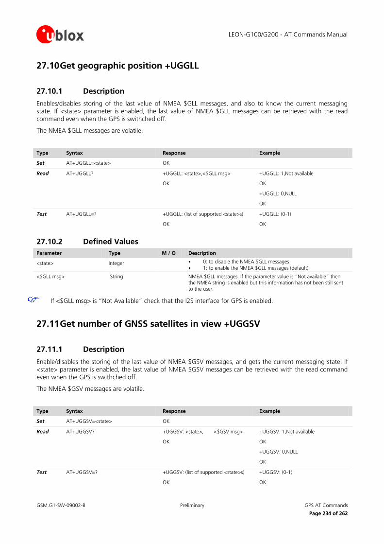
LEON-G100/G200 - AT Commands Manual
GSM.G1-SW-09002-B Preliminary GPS AT Commands
Page 234 of 262
27.10 Get geographic position +UGGLL
27.10.1 Description
Enables/disables storing of the last value of NMEA $GLL messages, and also to know the current messaging state. If <state> parameter is enabled, the last value of NMEA $GLL messages can be retrieved with the read
command even when the GPS is swithched off.
The NMEA $GLL messages are volatile.
Type Syntax Response Example
Set AT+UGGLL=<state> OK
Read AT+UGGLL? +UGGLL: <state>,<$GLL msg>
OK
+UGGLL: 1,Not available
OK
+UGGLL: 0,NULL
OK
Test AT+UGGLL=? +UGGLL: (list of supported <state>s)
OK
+UGGLL: (0-1)
OK
27.10.2 Defined Values
Parameter Type M / O Description
<state> Integer 0: to disable the NMEA $GLL messages
1: to enable the NMEA $GLL messages (default)
<$GLL msg>
String NMEA $GLL messages. If the parameter value is “Not available” then the NMEA string is enabled but this information has not been still sent to the user.
If <$GLL msg> is “Not Available” check that the I2S interface for GPS is enabled.
27.11 Get number of GNSS satellites in view +UGGSV
27.11.1 Description
Enable/disables the storing of the last value of NMEA $GSV messages, and gets the current messaging state. If
<state> parameter is enabled, the last value of NMEA $GSV messages can be retrieved with the read command even when the GPS is swithched off.
The NMEA $GSV messages are volatile.
Type Syntax Response Example
Set AT+UGGSV=<state> OK
Read AT+UGGSV? +UGGSV: <state>, <$GSV msg>
OK
+UGGSV: 1,Not available
OK
+UGGSV: 0,NULL
OK
Test AT+UGGSV=? +UGGSV: (list of supported <state>s)
OK
+UGGSV: (0-1)
OK

LEON-G100/G200 - AT Commands Manual
GSM.G1-SW-09002-B Preliminary GPS AT Commands
Page 235 of 262
27.11.2 Defined Values
Parameter Type M / O Description
<state> Integer 0: to disable the NMEA $GSV messages
1: to enable the NMEA $GSV messages (default)
<$GSV msg>
String NMEA $GSV messages. If the parameter value is “Not available” then the NMEA string is enabled but this information has not been still sent to the user.
If <$GSV msg> is “Not Available” check that the I2S interface for GPS is enabled.
27.12 Get recommended minimum GNSS data +UGRMC
27.12.1 Description
Enable/disables storing of the last value of NMEA $RMC messages, and gets the current messaging state. If
<state> parameter is enabled, the last value of NMEA $RMC messages can be retrieved with the read command
even when the GPS is swithched off.
The NMEA $RMC messages are volatile.
Type Syntax Response Example
Set AT+UGRMC=<state> OK
Read AT+UGRMC? +UGRMC: <state>, <$RMC msg>
OK
+UGRMC: 1,Not available
OK
+UGRMC: 0,NULL
OK
Test AT+UGRMC=? +UGRMC: (list of supported <state>s)
OK
+UGRMC: (0-1)
OK
27.12.2 Defined Values
Parameter Type M / O Description
<state> Integer 0: to disable the NMEA $RMC messages
1: to enable the NMEA $RMC messages (default)
<$RMC msg>
String NMEA $RMC messages. If the parameter value is “Not available” then the NMEA string is enabled but this information has not been still sent to the user.
If <$RMC msg> is “Not Available” check that the I2S interface for GPS is enalbled.
27.13 Get course over ground and ground speed +UGVTG
27.13.1 Description
Enables/disables storing of the last value of NMEA $VTG messages, and gets know the current messaging state. If <state> parameter is enabled, the last value of NMEA $VTG messages can be retrieved with the read
command even when the GPS is swithched off.
The NMEA $VTG messages are volatile.

LEON-G100/G200 - AT Commands Manual
GSM.G1-SW-09002-B Preliminary GPS AT Commands
Page 236 of 262
Type Syntax Response Example
Set AT+UGVTG=<state> OK
Read AT+UGVTG? +UGVTG: <state>, <$VTG msg>
OK
+UGVTG: 1,Not available
OK
+UGVTG: 0,NULL
OK
Test AT+UGVTG=? +UGVTG: (list of supported <state>s)
OK
+UGVTG: (0-1)
OK
27.13.2 Defined Values
Parameter Type M / O Description
<state> Integer 0: to disable the NMEA $VTG messages
1: to enable the NMEA $VTG messages (default)
<$VTG msg>
String NMEA $VTG messages. If the parameter value is “Not available” then the NMEA string is enabled but this information has not been still sent to the user.
If <$VTG msg> is “Not Available” check that the I2S interface for GPS is enalbled.
27.14 Get course over ground and ground speed +UGGSA
27.14.1 Description
Enables/disables storing of the last value of NMEA $GSA messages, and gets the current messaging state. If <state> parameter is enabled, the last value of NMEA $GSA messages can be retrieved with the read command
even when the GPS is swithched off.
The NMEA $GSA messages are volatile.
Type Syntax Response Example
Set AT+UGGSA=<state> OK
Read AT+UGGSA? +UGGSA: <state>, <$VTG msg>
OK
+UGGSA: 1,Not available
OK
+UGGSA: 0,NULL
OK
Test AT+UGGSA=? +UGGSA: (list of supported <state>s)
OK
+UGGSA: (0-1)
OK
27.14.2 Defined Values
Parameter Type M / O Description
<state> Integer 0: to disable the NMEA $GSA messages
1: to enable the NMEA $GSA messages (default)
<$GSA msg>
String NMEA $GSA messages. If the parameter value is “Not available” then the NMEA string is enabled but this information has not been still sent to the user.
If <$GSA msg> is “Not Available” check that the I2S interface for GPS is enabled.

LEON-G100/G200 - AT Commands Manual
GSM.G1-SW-09002-B Preliminary Appendix
Page 237 of 262
Appendix
A Appendix 1
A.1 Networking Error
<err> Meaning Resulting from the following commands
0 OK, no error occurred
1 FTP Protocol error class
2 SMTP Protocol error class
3 HTTP Protocol error class
4 Flash File System error class
5 DNS error class
6 Socket error class
7 Dynamic Memory error
8 Wrong FTP API usage (e.g. missing/null parameters)
9 Wrong SMTP API usage (e.g. missing/null parameters)
10 Wrong HTTP API usage (e.g. missing/null parameters)
11 Syntax error in high layer Protocol (wrong/missing/corrupted data)
12 Unspecified error
A.2 Mobile Termination error result code +CME ERROR
<err> Meaning Resulting from the following commands
0 Phone failure undeterminated
1 No connection to phone
2 Phone-adaptor link reserved
3 Operation not allowed Refer to the footnote1
4 Operation not supported Refer to the footnote1
5 PH-SIM PIN required Refer to the footnote1
10 SIM not inserted Refer to the footnote1
11 SIM PIN required Refer to the footnote1
12 SIM PUK required Refer to the footnote1
13 SIM failure Refer to the footnote1
14 SIM busy Refer to the footnote1
1 +CACM, +CALA, +CALD,+CALM, +CAMM,+CAOC, +CBC,+CBST, +CCFC, +CCLK, +CCUG, +CCWA, +CCWE, +CEER, +CFUN, +CGACT, +CGATT, +CGCLASS, +CGDATA, +CGDCONT, +CGEREP, +CGMI, +CGMM, +CGMR, +CGPADDR, +CGQMIN, +CGQREQ, +CGREG, +CGSMS, +CGSN, +CHLD, +CHUP, +CIMI, +CIND, +CLAC, +CLCC, +CLCK, +CLIP, +CLIR, +CLVL, +CMEE, +CMER, +CMOD, +CMUT, +CMUX, +CNUM, +COLP, +COPS, +CPAS, +CPBF, +CPBR, +CPBS, +CPBW, +CPIN, +CPOL, +CPUC, +CPWD, +CR, +CRC, +CREG, +CRLP, +CRSL, +CRSM, +CSCS, +CSGT, +CSNS, +CSQ, +CSSN, +CSTA, +CTFR, +CTZR, +CTZU
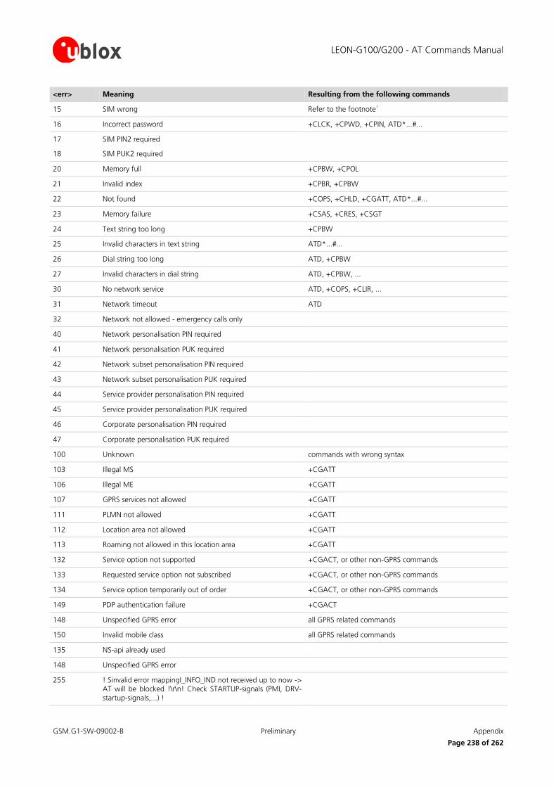
LEON-G100/G200 - AT Commands Manual
GSM.G1-SW-09002-B Preliminary Appendix
Page 238 of 262
<err> Meaning Resulting from the following commands
15 SIM wrong Refer to the footnote1
16 Incorrect password +CLCK, +CPWD, +CPIN, ATD*...#...
17 SIM PIN2 required
18 SIM PUK2 required
20 Memory full +CPBW, +CPOL
21 Invalid index +CPBR, +CPBW
22 Not found +COPS, +CHLD, +CGATT, ATD*...#...
23 Memory failure +CSAS, +CRES, +CSGT
24 Text string too long +CPBW
25 Invalid characters in text string ATD*...#...
26 Dial string too long ATD, +CPBW
27 Invalid characters in dial string ATD, +CPBW, ...
30 No network service ATD, +COPS, +CLIR, ...
31 Network timeout ATD
32 Network not allowed - emergency calls only
40 Network personalisation PIN required
41 Network personalisation PUK required
42 Network subset personalisation PIN required
43 Network subset personalisation PUK required
44 Service provider personalisation PIN required
45 Service provider personalisation PUK required
46 Corporate personalisation PIN required
47 Corporate personalisation PUK required
100 Unknown commands with wrong syntax
103 Illegal MS +CGATT
106 Illegal ME +CGATT
107 GPRS services not allowed +CGATT
111 PLMN not allowed +CGATT
112 Location area not allowed +CGATT
113 Roaming not allowed in this location area +CGATT
132 Service option not supported +CGACT, or other non-GPRS commands
133 Requested service option not subscribed +CGACT, or other non-GPRS commands
134 Service option temporarily out of order +CGACT, or other non-GPRS commands
149 PDP authentication failure +CGACT
148 Unspecified GPRS error all GPRS related commands
150 Invalid mobile class all GPRS related commands
135 NS-api already used
148 Unspecified GPRS error
255 ! Sinvalid error mappingI_INFO_IND not received up to now -> AT will be blocked !\r\n! Check STARTUP-signals (PMI, DRV-startup-signals,...) !

LEON-G100/G200 - AT Commands Manual
GSM.G1-SW-09002-B Preliminary Appendix
Page 239 of 262
<err> Meaning Resulting from the following commands
254 Invalid error mapping
701 incorrect security code
702 max attempts reached
1001 Unassigned (unallocated) number
1003 No rout to destination
1006 Channel unacceptable
1008 Operator determined barring
1016 Normal call clearing
1017 User busy
1018 No user responding
1019 User alerting, no answer
1021 Call rejected
1022 Number changed
1026 Non selected user clearing
1027 Destination out of order
1028 Invalid number format (incomplete number)
1029 Facility rejected
1030 Response to STATUS ENQUIRY
1031 Normal, unspecified
1034 No circuit/channel available
1038 Network out of order
1041 Temporary failure
1042 Switching equipment congestion
1043 Access information discarded
1044 requested circuit/channel not available
1047 Resources unavailable, unspecified
1049 Quality of service unavailable
1050 Requested facility not subscribed
1055 Incoming calls barred within the CUG
1057 Bearer capability not authorized
1058 Bearer capability not presently available
1063 Service or option not available, unspecified
1065 Bearer service not implemented
1068 ACM equal to or greater than ACMmax
1069 Requested facility not implemented
1070 Only restricted digital information bearer capability is available
1079 Service or option not implemented, unspecified
1081 Invalid transaction identifier value
1087 User not member of CUG
1088 Incompatible destination

LEON-G100/G200 - AT Commands Manual
GSM.G1-SW-09002-B Preliminary Appendix
Page 240 of 262
<err> Meaning Resulting from the following commands
1091 Invalid transit network selection
1095 Semantically incorrect message
1096 Invalid mandatory information
1097 Message type non-existent or not implemented
1098 Message type not compatible with protocol state
1099 Information element non-existent or not implemented
1100 Conditional IE error
1101 Message not compatible with protocol state
1102 Recovery on timer expiry
1111 Protocol error, unspecified
1127 Interworking, unspecified
1279 Number not allowed
1283 CCBS possible
1500 Wrong GPIO identifier +UGPIOC, +UGPIOR, +UGPIOW
1501 Set GPIO default error +UGPIOC
1502 Select GPIO mode error +UGPIOC
1503 Read GPIO error +UGPIOR
1504 Write GPIO error +UGPIOW
1520 Wrong ADC identifier +UADC
1521 Read ADC error +UADC
1540 Wrong ringer identifier +URNG
1550 GPRS generic operation error
1551 GPRS invalid APN
1552 GPRS authentication failure
1553 GPRS QoS parameters inconsistent
1554 GPRS network failure
1555 GPRS context busy
1556 CSD generic operation error
1557 CSD undefined profile
1558 CSD context busy
1600 FFS error
1612 File not found +UPLAYFILE, +UDELFILE
A.3 Message service failure result codes +CMS ERROR
<err> Meaning Resulting from the following commands
1 Unassigned (unallocated) number
8 Operator determined barring
10 Call barred
17 Network failure
21 Short message transfer rejected

LEON-G100/G200 - AT Commands Manual
GSM.G1-SW-09002-B Preliminary Appendix
Page 241 of 262
<err> Meaning Resulting from the following commands
22 Memory capacity exceeded
27 Destination out of service
28 Unidentified subscriber
29 Facility rejected
30 Unknown Subscriber
38 Network out of order
41 Temporary failure
42 Congestion
47 Resources unavailable, unspecified
50 Requested facility not subscribed
69 Requested facility not implemented
81 Invalid short message reference value
95 Invalid message, unspecified
96 invalid mandatory information
97 Message type non-existent or not implemented
98 Message not compatible with short message protocol state
99 Information element non-existent or not implemented
111 Protocol error, unspecified
127 Interworking, unspecified
128 Telematic interworking not supported
129 Short message type 0 not supported
130 Cannot replace short message
143 Unspecified TP-PID error
144 Data coding scheme (alphabet) not supported
145 Message class not supported
159 Unspecified TP-DCS error
160 Command cannot be actioned
161 Command unsupported
175 Unspecified TP-Command error
176 TPDU not supported
192 SC busy
193 No SC subscription
194 SC system failure
195 Invalid SME address
196 Destination SME barred
197 SM Rejected-Duplicate SM
198 TP-VPF not supported
199 TP-VP not supported
208 SIM SMS storage full
209 No SMS storage capability in SIM

LEON-G100/G200 - AT Commands Manual
GSM.G1-SW-09002-B Preliminary Appendix
Page 242 of 262
<err> Meaning Resulting from the following commands
210 Error in MS
211 Memory Capacity Exceeded
212 SIM Application Toolkit Busy
213 SIM data download error
224 TP_FCS_APPL_ERR_START
254 TP_FCS_APPL_ERR_STOP
255 TP_FCS_UNSPECIFIED
300 ME failure
301 SMS service of ME reserved +CSMS
302 Operation not allowed all SMS commands
303 operation not supported all SMS commands
305 Invalid Text mode parameter
310 SIM not inserted all SMS commands
311 SIM PIN necessary all SMS commands
312 PH-SIM PIN necessary all SMS commands
313 SIM failure all SMS commands
314 SIM busy all SMS commands
315 SIM wrong all SMS commands
320 memory failure +CMGR
321 invalid memory index +CMGR, +CMGL
322 memory full
330 SMSC address unknown +CMGR
331 no network service
332 network timeout +CNMA
500 unknown error commands with wrong syntax
512 MN_SMS_RP_ACK This and the following codes are manufacturer specific
513 MN_SMS_TIMER_EXPIRED
514 MN_SMS_FORW_AVAIL_FAILED
515 MN_SMS_FORW_AVAIL_ABORTED
516 MS invalid TP-Message-Type-Indicator
517 MS no TP-Status-Report in Phase 1
518 MS no TP-Reject-Duplicate in phase 1
519 MS no TP-Replay-Path in Phase 1
520 MS no TP-User-Data-Header in Phase 1
521 MS missing TP-Validity-Period
522 MS invalid TP-Service-Centre-Time-Stamp
523 MS missing TP-Destination- Address
524 MS invalid TP-Destination-Address
525 MS missing Service-Centre-Address
526 MS invalid Service-Centre-Address

LEON-G100/G200 - AT Commands Manual
GSM.G1-SW-09002-B Preliminary Appendix
Page 243 of 262
<err> Meaning Resulting from the following commands
527 MS invalid alphabet
528 MS invalid TP-User-Data-length
529 MS missing TP-User-Data
530 MS TP-User-Data to long
531 MS no Command-Request in Phase 1
532 MS Cmd-Req invalid TP-Destination-Address
533 MS Cmd-Req invalid TP-User-Data-Length
534 MS Cmd-Req invalid TP-User-Data
535 MS Cmd-Req invalid TP-Command-Type
536 MN MNR creation failed
537 MS CMM creation failed
538 MS network connection lost
539 MS pending MO SM transfer
540 RP-Error OK
541 RP-Error OK no icon display
542 SMS-PP Unspecified
543 SMS rejected By SMS CONTROL
B AT Commands List Legend:
: the parameters of the command can be saved in the profiles stored internally in the non volatile
memory;
: the command needs of the SIM module to work correctly;
: the command needs of the PIN insertion to work correctly;
: the parameter of the command can be stored in the non volatile memory of the module.
: the command is abortable by hitting a key
AT command LEON-G100 LEON-G200 Supported Feature
&A
&B
&C
&D
&E
PRF
PRF
PRF
SIM
PIN
NVM
PIN
ABT

LEON-G100/G200 - AT Commands Manual
GSM.G1-SW-09002-B Preliminary Appendix
Page 244 of 262
AT command LEON-G100 LEON-G200 Supported Feature
&F
&H
&I
&K
&M
&R
&S
&V
&W
&Y
\Q
+CACM
+CALA
+CALD
+CALM
+CAMM
+CAOC
+CBC
+CBST
+CCFC
+CCID
+CCLK
+CCUG
+CCWA
+CCWE
+CEER
+CFUN
+CGACT
+CGATT
+CGCLASS
PRF
PRF
NVM
NVM
NVM
NVM
NVM
PIN
PIN
PIN
PIN
PIN
PIN
PIN
PIN
PIN
PIN
PIN
SIM
SIM
SIM
PIN
PIN
ABT
ABT

LEON-G100/G200 - AT Commands Manual
GSM.G1-SW-09002-B Preliminary Appendix
Page 245 of 262
AT command LEON-G100 LEON-G200 Supported Feature
+CGDATA
+CGDCONT
+CGED
+CGEREP
+CGMI
+CGMM
+CGMR
+CGPADDR
+CGQMIN
+CGQREQ
+CGREG
+CGSMS
+CGSN
+CHLD
+CHUP
+CIMI
+CIND
+CLAC
+CLCC
+CLCK
+CLIP
+CLIR
+CLVL
+CMEE
+CMER
+CMGD
+CMGF
+CMGL
+CMGR
NVM
NVM
PIN
PIN
PIN
PIN
PIN
PIN
PIN
PIN
PIN
PIN
PIN
PIN
PIN
PIN
PIN
PIN
PIN
PIN
ABT
ABT
ABT
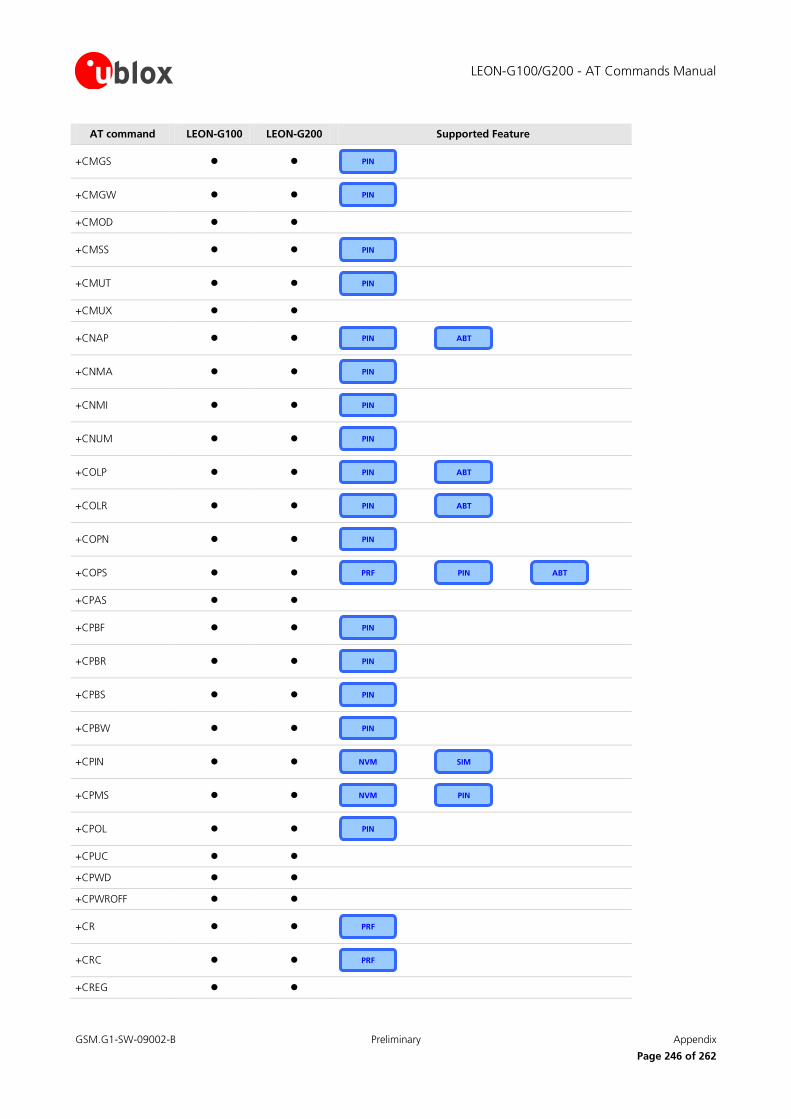
LEON-G100/G200 - AT Commands Manual
GSM.G1-SW-09002-B Preliminary Appendix
Page 246 of 262
AT command LEON-G100 LEON-G200 Supported Feature
+CMGS
+CMGW
+CMOD
+CMSS
+CMUT
+CMUX
+CNAP
+CNMA
+CNMI
+CNUM
+COLP
+COLR
+COPN
+COPS
+CPAS
+CPBF
+CPBR
+CPBS
+CPBW
+CPIN
+CPMS
+CPOL
+CPUC
+CPWD
+CPWROFF
+CR
+CRC
+CREG
PRF
PRF
PRF
NVM
NVM
PIN
PIN
PIN
PIN
PIN
PIN
PIN
PIN
PIN
PIN
PIN
PIN
PIN
PIN
PIN
PIN
PIN
PIN
SIM
ABT
ABT
ABT
ABT

LEON-G100/G200 - AT Commands Manual
GSM.G1-SW-09002-B Preliminary Appendix
Page 247 of 262
AT command LEON-G100 LEON-G200 Supported Feature
+CRES
+CRLP
+CRSL
+CRSM
+CSAS
+CSCA
+CSCB
+CSCS
+CSDH
+CSGT
+CSMP
+CSMS
+CSNS
+CSQ
+CSSN
+CSTA
+CTFR
+CTZR
+CTZU
+CUSD
+CUUS1
+FAA
+FAP
+FBO
+FBS
+FBU
+FCC
PRF
NVM
NVM
NVM
PIN
PIN
PIN
PIN
PIN
PIN
PIN
PIN
PIN
PIN
PIN
PIN
PIN
PIN
PIN
PIN
PIN
PIN
PIN
PIN
PIN

LEON-G100/G200 - AT Commands Manual
GSM.G1-SW-09002-B Preliminary Appendix
Page 248 of 262
AT command LEON-G100 LEON-G200 Supported Feature
+FCLASS
+FCQ
+FCR
+FCS
+FCT
+FDR
+FDT
+FEA
+FFC
+FFD
+FHS
+FIE
+FIP
+FIS
+FIT
+FKS, +FK
+FLI
+FLO
+FLP
+FMI
+FMM
+FMR
+FMS
+FND
+FNR
+FNS
+FPA
PIN
PIN
PIN
PIN
PIN
PIN
PIN
PIN
PIN
PIN
PIN
PIN
PIN
PIN
PIN
PIN
PIN
PIN
PIN
PIN
PIN
PIN
PIN

LEON-G100/G200 - AT Commands Manual
GSM.G1-SW-09002-B Preliminary Appendix
Page 249 of 262
AT command LEON-G100 LEON-G200 Supported Feature
+FPI
+FPP
+FPS
+FPW
+FRQ
+FRY
+FSA
+FSP
+GCAP
+GMI
+GMM
+GMR
+GSN
+ICF
+IFC
+IPR
+STKENV
+STKPRO
+STKPROF
+STKTR
+UADC
+UANTR
+UBANDSEL
+UCALLSTAT
+UCD
+UCGOPS
+UCSD
+UCSDA
+UCSND
+UDBF
PRF
NVM
NVM
PRF
PIN
PIN
PIN
PIN
PIN
PIN
PIN
PIN
PIN
PIN
PIN
PIN
PIN
ABT
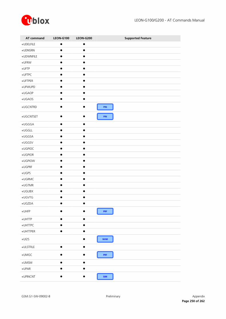
LEON-G100/G200 - AT Commands Manual
GSM.G1-SW-09002-B Preliminary Appendix
Page 250 of 262
AT command LEON-G100 LEON-G200 Supported Feature
+UDELFILE
+UDNSRN
+UDWNFILE
+UFRW
+UFTP
+UFTPC
+UFTPER
+UFWUPD
+UGAOP
+UGAOS
+UGCNTRD
+UGCNTSET
+UGGGA
+UGGLL
+UGGSA
+UGGSV
+UGPIOC
+UGPIOR
+UGPIOW
+UGPRF
+UGPS
+UGRMC
+UGTMR
+UGUBX
+UGVTG
+UGZDA
+UHFP
+UHTTP
+UHTTPC
+UHTTPER
+UI2S
+ULSTFILE
+UMGC
+UMSM
+UPAR
+UPINCNT
NVM
PRF
PRF
PIN
PIN
SIM

LEON-G100/G200 - AT Commands Manual
GSM.G1-SW-09002-B Preliminary Appendix
Page 251 of 262
AT command LEON-G100 LEON-G200 Supported Feature
+UPLAYFILE
+UPSD
+UPSDA
+UPSND
+UPSV
+URDFILE
+URNG
+USAR
+USGC
+USMTP
+USMTPC
+USMTPER
+USMTPM
+USOCL
+USOCO
+USOCR
+USOER
+USOGO
+USOLI
+USORD
+USOSO
+USOWR
+USPM
+USTN
+USTOPFILE
+UTGN
+UUBF
+VTD
+VTS
A
A/
B
D
DL
PRF
NVM
NVM
NVM
NVM
PRF
PRF
PRF
PIN
PIN
SIM
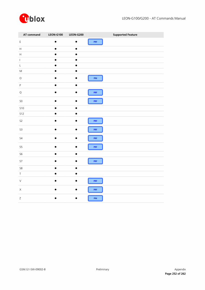
LEON-G100/G200 - AT Commands Manual
GSM.G1-SW-09002-B Preliminary Appendix
Page 252 of 262
AT command LEON-G100 LEON-G200 Supported Feature
E
H
H
I
L
M
O
P
Q
S0
S10
S12
S2
S3
S4
S5
S6
S7
S8
T
V
X
Z
PRF
PRF
PRF
PRF
PRF
PRF
PRF
PRF
PRF
PRF
PIN
PIN
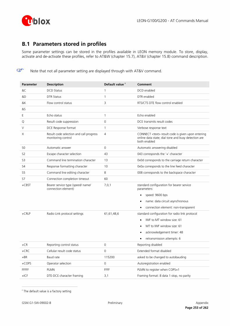
LEON-G100/G200 - AT Commands Manual
GSM.G1-SW-09002-B Preliminary Appendix
Page 253 of 262
B.1 Parameters stored in profiles
Some parameter settings can be stored in the profiles available in LEON memory module. To store, display,
activate and de-activate these profiles, refer to AT&W (chapter 15.7), AT&V (chapter 15.8) command description.
Note that not all parameter setting are displayed through with AT&V command.
Parameter Description Default value 2 Comment
&C DCD Status 1 DCD enabled
&D DTR Status 1 DTR enabled
&K Flow control status 3 RTS/CTS DTE flow control enabled
&S
E Echo status 1 Echo enabled
Q Result code suppression 0 DCE transmits result codes
V DCE Response format 1 Verbose response text
X Result code selection and call progress monitoring control
4 CONNECT <text> result code is given upon entering online data state; dial tone and busy detection are both enabled
S0 Automatic answer 0 Automatic answering disabled
S2 Escape character selection 43 043 corresponds the ‘+’ character
S3 Command line termination character 13 0x0d corresponds to the carriage return character
S4 Response formatting character 10 0x0a corresponds to the line feed character
S5 Command line editing character 8 008 corresponds to the backspace character
S7 Connection completion timeout 60
+CBST Bearer service type (speed/ name/ connection element)
7,0,1 standard configuration for bearer service parameters:
speed: 9600 bps
name: data circuit asynchronous
connection element: non-transparent
+CRLP Radio Link protocol settings 61,61,48,6 standard configuration for radio link protocol
IWF to MT window size: 61
MT to IWF window size: 61
acknowledgement timer: 48
retransmission attempts: 6
+CR Reporting control status 0 Reporting disabled
+CRC Cellular result code status 0 Extended format disabled
+BR Baud rate 115200 asked to be changed to autobauding
+COPS Operator selection 0 Autoregistration enabled
FFFFF PLMN FFFF PLMN to register when COPS=1
+ICF DTE-DCE character framing 3,1 Framing format: 8 data 1 stop, no parity
2 The default value is a factory setting

LEON-G100/G200 - AT Commands Manual
GSM.G1-SW-09002-B Preliminary Appendix
Page 254 of 262
Parameter Description Default value 2 Comment
+UPSV: 1,1 Power Saving (mode, timeout) 1,2000 Power saving enabled with a predefined timeout of 2000 GSM frames
+UMGC Microphone Gain Control Path 0: 10,9384
Path 1: 12,8192
Path 2: 6,8192
Path 0:
Analog gain:10, Digital gain: 9384
Path 1:
Analog gain:12, Digital gain: 8192
Path 2:
Analog gain:6, Digital gain: 8192
+USGC Speaker Gain Control Path 0: 6, 1, 8192, 16384, 8192
Path 1: 6, 0, 8192, 16384, 10240
Path 3: 0, 6, 8192, 16384, 8191
Path 4: 6, 6, 8192, 16384, 8191
Path 0:
Speaker gain: 6, Headset gain: 1, speech
and Tone Generator gain: 8192, Synthetizers gain: 16384, Speech gain: 8192
Path 1:
Speaker gain:6, Headset gain:0, speech and
Tone Generator gain: 8192, Synthetizers
gain: 16384, Speech gain:10240
Path 3:
Speaker gain: 0, Headset gain: 6, speech
and Tone Generator gain: 8192, Synthetizers gain:16384, Speech gain: 8191
Path 4:
Speaker gain: 6, Headset gain: 6, speech and Tone
Generator gain: 8192, Synthetizers gain: 16384, Speech gain: 8191
+USTN Sidetone Path 0: 2249
Path 1: 2249
Path 3: 0
Path 4: 0
Path 0:
Gain for side tone: 2249
Path 1:
Gain for side tone: 2249
Path 3:
Gain for side tone: 0
Path 4:
Gain for side tone: 0
+UUBF Uplink Digital Filters (Uplink Biquad Filters)
Path 0:
Filter1: -13915, 2249, 4377, -325, 23450
Filter2: 21682, -2312, 17984, -15517, 32767
Path 1:
Filter1: -29322, -29141, 29322, 26240, 29322
Filter2: 29322, 29141, 29322, 26240, 29322
Path 2:
Filter1: 0, 0, 0, 0,
Path 0:
Filter1: a1:-13915, b1:2249, a2:4377, b2:-325, a0:23450
Filter2: a1:21682, b1:-2312, a2:17984, b2:-15517, a0:32767
Path 1:
Filter1: a1:-29322, b1:-29141, a2:29322, b2:26240, a0:29322
Filter2: a1:29322, b1:29141, a2:29322, b2:26240, a0:29322
Path 2:
Filter1: a1:0, b1:0, a2:0, b2:0, a0:32767
Filter2: a1:0, b1:0, a2:0, b2:0, a0:32767

LEON-G100/G200 - AT Commands Manual
GSM.G1-SW-09002-B Preliminary Appendix
Page 255 of 262
Parameter Description Default value 2 Comment
32767
Filter2: 0, 0, 0, 0, 32767
+UDBF Downlink Biquad Digital Filters Path 0:
Filter1: 0, 0, 0, 0, 32767
Filter2: 0, 0, 0, 0, 32767
Path 1:
Filter1: -29322, -29141, 29322, 26240, 29322
Filter2: 29322, 29141, 29322, 26240, 29322
Path 3:
Filter1: 0, 0, 0, 0, 32767
Filter2: 0, 0, 0, 0, 32767
Path 4:
Filter1: 0, 0, 0, 0, 32767
Filter2: 0, 0, 0, 0, 32767
Path 0:
Filter1: a1:0, b1:0, a2:0, b2:0, a0:32767
Filter2: a1:0, b1:0, a2:0, b2:0, a0:32767
Path 1:
Filter1: a1:-29322, b1:-29141, a2:29322, b2:26240, a0:29322
Filter2: a1:29322, b1:29141, a2:29322, b2:26240, a0:29322
Path 3:
Filter1: a1:0, b1:0, a2:0, b2:0, a0:32767
Filter2: a1:0, b1:0, a2:0, b2:0, a0:32767
Path 4:
Filter1: a1:0, b1:0, a2:0, b2:0, a0:32767
Filter2: a1:0, b1:0, a2:0, b2:0, a0:32767
+UHFP Hand Free Parameters Path 0:
0x01fd, 0x016e, 2200, 250, 3, 5, 150, 0, 0, 500, 4096, 16384, 16384
Path 1:
0x01fd, 0x016e, 2200, 250, 3, 5, 150, 0, 0, 500, 4096, 16384, 16384
Path 2:
0x01fd, 0x016e, 2200, 250, 8, 5, 150, 0, 0, 500, 4096, 16384, 16384
Path 0:
HF_algorithm_init:0x01fd, HF_Algorithm_Restart:0x016e, Step_Width:2200, LMS_Length:250, LMS_Offset:3, Block_Length:5, RXTX_Relation:150, Add_Atten:0, Min_Atten:0, Max_Atten:500, NR_sw_2:4096, NR_u_fak_0:16384, NR_u_fak:16384
Path 1:
HF_algorithm_init:0x01fd, HF_Algorithm_Restart:0x016e, Step_Width:2200, LMS_Length:250, LMS_Offset:3, Block_Length:5, RXTX_Relation:150, Add_Atten:0, Min_Atten:0, Max_Atten:500, NR_sw_2:4096, NR_u_fak_0:16384, NR_u_fak:16384
Path 2:
HF_algorithm_init:0x01fd, HF_Algorithm_Restart:0x016e, Step_Width:2200, LMS_Length:250, LMS_Offset:8, Block_Length:5, RXTX_Relation:150, Add_Atten:0, Min_Atten:0, Max_Atten:500, NR_sw_2:4096, NR_u_fak_0:16384, NR_u_fak:16384

LEON-G100/G200 - AT Commands Manual
GSM.G1-SW-09002-B Preliminary Appendix
Page 256 of 262
B.2 Parameters stored in non volatile memory
Parameter Description Default value Comment
+CALM Alert sound mode 0 Mute disabled
+CRSL Ringer sound level 4 Ringer sound level: 4
+CGSMS Select service for MO SMS messages 0 GPRS service enabled
+CLVL Speech volume level 80 Speech volume level: 80
+CMUT Mute control 0 Mute disabled
+URNG Ringing tone selection 0 “pinkpanther” melody
+UMSM SMS Alert sound mode 0 Normal mode
+UI2S I2S Digital Interface Mode 4,2,1 I2S mode: normal mode 4
I2S port: I2Sy
I2S_CLK and I2S_WA signals are active in continuos mode
+USPM Audio Path mode setting 0,0,1,1 Speech audio output path: Handset microphone
Speech audio input path: Normal earpiece
Alert sound on Loudspeaker
Headset indication: considered
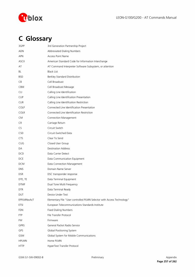
LEON-G100/G200 - AT Commands Manual
GSM.G1-SW-09002-B Preliminary Appendix
Page 257 of 262
C Glossary 3GPP 3rd Generation Partnership Project
ADN Abbreviated Dialing Numbers
APN Access Point Name
ASCII American Standard Code for Information Interchange
AT AT Command Interpreter Software Subsystem, or attention
BL Black List
BSD Berkley Standard Distribution
CB Cell Broadcast
CBM Cell Broadcast Message
CLI Calling Line Identification
CLIP Calling Line Identification Presentation
CLIR Calling Line Identification Restriction
COLP Connected Line Identification Presentation
COLR Connected Line Identification Restriction
CM Connection Management
CR Carriage Return
CS Circuit Switch
CSD Circuit-Switched Data
CTS Clear To Send
CUG Closed User Group
DA Destination Address
DCD Data Carrier Detect
DCE Data Communication Equipment
DCM Data Connection Management
DNS Domain Name Server
DSR DSC transponder response
DTE, TE Data Terminal Equipment
DTMF Dual Tone Multi Frequency
DTR Data Terminal Ready
DUT Device Under Test
EFPLMNwAcT Elementary File "User controlled PLMN Selector with Access Technology"
ETSI European Telecommunications Standards Institute
FDN Fixed Dialing Numbers
FTP File Transfer Protocol
FW Firmware
GPRS General Packet Radio Service
GPS Global Positioning System
GSM Global System for Mobile Communications
HPLMN Home PLMN
HTTP HyperText Transfer Protocol

LEON-G100/G200 - AT Commands Manual
GSM.G1-SW-09002-B Preliminary Appendix
Page 258 of 262
I Information
ICCID Integrated Circuit Card ID
ICMP Internet Control Message Protocol
IMEI International Mobile Equipment Identity
IMSI International Mobile Station Identity
IP Internet Protocol
IRA International Reference Alphabet
IRC Intermediate Result Code
ISDN Integrated Services Digital Network
ISP Internet Service Provider
L3 Layer 3
LF Line Feed
M2M Machine-To-Machine
MCC Mobile Country Code
ME Mobile Equipment
MMI Man Machine Interface
MN Mobile Network Software Subsystem
MNC Mobile Network Code
MO Mobile Originated
MS Mobile Station
MSISDN Mobile Systems International Subscriber Identity Number
MT Mobile Terminated
NITZ Network Identity and Time Zone
NVM Non-Volatile Memory
NVRAM Not Volatile RAM
OLCM On Line Commands Mode
PAD Packet Assembler/Disassembler
PDP Packet Data Protocol
PDU Protocol Data Unit
PIN Personal Identification Number
PLMN Public Land Mobile Network
PSD Packet-Switched Data
PUK Personal Unblocking Key
QoS Quality of Service
RAM Random Access Memory
RFU Reserved for Future Use
RI Ring Indicator
RTC Real Time Clock
RTS Request To Send
Rx Receiver
SC Service Centre
SI SIM Application Part Software Subsystem

LEON-G100/G200 - AT Commands Manual
GSM.G1-SW-09002-B Preliminary Appendix
Page 259 of 262
SIM Subscriber Identity Module
SMS Short Message Service
SMSC Short Message Service Center
SMTP Simple Mail Transfer Protocol
TA Terminal Adaptor
TCP Transfer Control Protocol
TE Terminal Equipment
TP Transfer layer Protocol
Tx Transmitter
TZ Time Zone
UCS2 Universal Character Set
UDP User Datagram Protocol
UI Unnumbered Information
UIH Unnumbered Information with header Check
URC Unsolicited Result Code
USIM UMTS Subscriber Identity Module
UUS1 User-to-User Signalling Supplementary Service 1
LEON-G100/G200 - AT Commands Manual
GSM.G1-SW-09002-B Preliminary Related documents
Page 260 of 262
Related documents [1] Stevens. TCP/IP Illustrated Volume1 & 2 Addison-Wesley, 1994.
[2] 3GPP TS 27.007 Technical Specification Group Core Network and Terminals; AT command set for User Equipment (UE)
[3] 3GPP TS 22.004 General on supplementary services
[4] GSM 02.04 - Digital cellular telecommunication system (Phase 2+); Mobile Stations (MS) features
[5] 3GPP TS 22.030 - Man-Machine Interface (MMI) of the User Equipment (UE)
[6] 3GPP TS 22.090 Unstructured Supplementary Service Data (USSD); Stage 1
[7] 3GPP TS 23.038 - Alphabets and language-specific information
[8] 3GPP TS 23.040 - Technical realization of Short Message Service (SMS)
[9] 3GPP TS 23.041 - Technical realization of Cell Broadcast Service (CBS)
[10] 3GPP TS 23.060 - Technical Specification Group Services and System Aspects; General Packet Radio Service (GPRS); Service description
[11] 3GPP TS 24.007 Mobile radio interface signalling layer 3; General aspects
[12] 3GPP TS 24.008 - Mobile radio interface layer 3 specification
[13] 3GPP TS 24.011 Point-to-point (PP) Short Message Service (SMS) support on mobile radio interface
[14] GSM 04.12 - Digital cellular telecommunications system (Phase 2+); Short Message Service Cell
Broadcast (SMSCB) Support on Mobile Radio Interface.
[15] 3GPP TS 22.030 - Digital cellular telecommunications system (Phase 2+); Universal Mobile
Telecommunications System (UMTS); Man-Machine Interface (MMI) of the User Equipment (UE)
[16] 3GPP TS 27.005 - Technical Specification Group Terminals; Use of Data Terminal Equipment - Data Circuit terminating Equipment (DTE-DCE) interface for Short Message Services (SMS) and Cell
Broadcast Service (CBS)
[17] 3GPP TS 27.060 - Technical Specification Group Core Network; Packet Domain; Mobile Station (MS) supporting Packet Switched Services
[18] GSM 11.11 Digital cellular telecommunications system (Phase 2+); Specification of the Subscriber
Identity Module – Mobile Equipment (SIM – ME) interface
[19] 3GPP TS 31.102 Characteristics of the Universal Subscriber Identity Module (USIM) application
[20] ITU-T Recommendation V250, 05-99.
[21] ITU-T V.25ter ITU-T V.25 ter Recommendation: Data Communications over the Telephone Network; Serial asynchronous automatic Dialling and control.
[22] ITU-T T.32 ITU-T Recommendation T.32 Asynchronous Facsimile DCE Control - Service Class 2
[23] ISO 639 (1988) Code for the representation of names of languages
[24] LEON-G100/G200 Datasheet Doc No GSM.G1-HW-09001
[25] LEON-G100/G200 System Integration Manual Doc No GSM.G1-HW-09002
[26] ITU-T Recommendation V24, 02-2000. List of definitions for interchange circuits between Data Terminal Equipment (DTE) and Data Connection Equipment (DCE).
[27] RFC 791 - Internet Protocol - http://www.ietf.org/rfc/rfc791.txt
[28] 3GPP TS 05.08 Radio subsystem link control

LEON-G100/G200 - AT Commands Manual
GSM.G1-SW-09002-B Preliminary Revision history
Page 261 of 262
[29] 3GPP TS 22.087 User-to-User Signalling (UUS)
[30] 3GPP TS 24.008 Mobile radio interface layer 3 specification
[31] 3GPP TS 22.022 Personalisation of Mobile Equipment (ME)
[32] 3GPP TS 22.082 Call Forwarding (CF) supplementary services
[33] 3GPP TS 22.083 Call Waiting (CW) and Call Holding (HOLD)
[34] 3GPP TS 22.081 Line identification Supplementary Services- Stage 1
[35] 3GPP TS 23.081 Line identification supplementary services- Stage 2
[36] 3GPP TS 22.086 Advice of Charge (AoC) Supplementary Services
[37] 3GPP TS 22.024 Description of Charge Advice Information (CAI)
[38] 3GPP TS 22.085 Closed User Group (CUG) Supplementary Services
[39] 3GPP TS 22.096 Name identification supplementary services
[40] 3GPP TS 04.18 Mobile radio interface layer 3 specification; Radio Resource Control (RRC) protocol
[41] 3GPP TS 04.60 General Packet Radio Service (GPRS); Mobile Station (MS) - Base Station System (BSS) interface; Radio Link Control/ Medium Access Control (RLC/MAC) protocol
[42] 3GPP TS 05.02 Multiplexing and Multiple Access on the Radio Path
[43] EVK-G25H Evaluation Kit Getting Started Doc No. GSM.G1-EK-09022
For regular updates to u-blox documentation and to receive product change notifications please register
on our homepage.
Revision history Revision Date Name Status / Comments
- 30/04/2009 tgri Initial release
A 03/06/2009 lpah Change of status to Advance Information
B 19/08/2009 lpah Change of status to Preliminary
Added the description of the following commands: AT+UBANDSEL, AT+UCALLSTAT, AT+UGCNTRD, AT+UGCNTSET, AT+UPINCNT
AT&W: added the following note: “Profile parameter storage is executed as a background task which can not be controlled. In specific cases, it can happen that some parameters are not saved prior to a power loss.”
some commands which interact with ME are not accepted when ME is pending SIM PINPUK, ...
BECOME: some commands which interact with ME are not accepted when ME is pending SIM PIN, SIM PUK, ...
AT+UPSV: changed the parameter name <RX_Timeout> in <Timeout>. Udpated the description of the parameter
WAS: timeout in GSM frames without receiving chars on serial RX line
BECOME: timeout in GSM frames without receiving chars on serial TX line
LEON-G100/G200 - AT Commands Manual
GSM.G1-SW-09002-B Preliminary Contact
Page 262 of 262
Contact
For complete contact information visit us at www.u-blox.com
Headquarters
u-blox AG
Zuercherstrasse 68
CH-8800 Thalwil
Switzerland
Phone: +41 44 722 74 44 Fax: +41 44 722 74 47
E-mail: [email protected]
Offices
North, Central and South America
u-blox America, Inc.
Phone: +1 (703) 483 3180 E-mail: [email protected]
Regional Office West Coast:
Phone: +1 (703) 483 3184
E-mail: [email protected]
Technical Support:
Phone: +1 (703) 483 3185
E-mail: [email protected]
Europe, Middle East, Africa
u-blox AG
Phone: +41 44 722 74 44 E-mail: [email protected]
Support: [email protected]
Asia, Australia, Pacific
u-blox Singapore Pte. Ltd.
Phone: +65 6734 3811 E-mail: [email protected]
Support: [email protected]
Regional Office China:
Phone: +86 10 68 133 545
E-mail: [email protected] Support: [email protected]
Regional Office Japan:
Phone: +81 3 5775 3850
E-mail: [email protected]
Support: [email protected]
Regional Office Korea:
Phone: +82 2 542 0861 E-mail: [email protected]
Support: [email protected]
Regional Office Taiwan:
Phone: +886 2 2657 1090
E-mail: [email protected]
Support: [email protected]