Leon F. Galle & Andre G. van Erkel On TNO-PML …
15
Leon F. Galle & Andre G. van Erkel E-mail: [email protected] WWW.MinDef.nl E-mail: [email protected] WWW.TNO.NL On TNO-PML Developments of Blast Resistant Structures for the Royal Netherlands Navy (SHIP SURVIVABILITY PART IV-B) The article reflects the views of the authors and not necessarily those of the Royal Netherlands Navy and/or Prins Maurits Laboratory. This article is based on declassified information of the classified presentation The English language has been used for this article, since this publication is an edited and extended version of the one presented and published at the SAVIAC Shock & Vibration Symposium 2000, Washington, D.C. Leon F. Galle is Senior Ship Survivability, at the Department of Naval Architecture & Marine Engineering (MarTech), Directorate of Materiel of the Royal Netherlands Navy (RNLN). He was active for 6 years in the field of Ship Vulnerability at the Prins Maurits Laboratory of the Netherlands Organisation for Applied Scientific Research (TNO-PML). He started Survivability work (Above Water Signatures & Vulnerability) for the Royal Netherlands Navy (RNLN) in 1991. The author is national representative of NATO subgroup AC/141(NG/6)SG/7 "on Ship Combat Survivability" and manages several scientific research projects on ship RCS, IR and Vulnerability for the RNLN at TNO-FEL and TNO-PML. Arie (Andre) G. van Erkel is project leader at the Prins Maurits Laboratory of the Netherlands Organisation for Applied Scientific Research (TNO-PML) since 1985. In the group Platform Technology he is an expert on blast resistance of ship structures, for in- and external explosions. He is active in the field of computational modelling of gas dynamics and dynamic structural response. He is involved in several large-scale experiments and in the application of blast resistant structures (e.g. bulkheads, doors, boxgirders etc) onboard new ships. SYNOPSIS The impact of an Anti Ship Missile is one of the most threatening scenarios for a naval ship. The accompanying warhead detonation will endanger crew, platform and its mission. A naval engineer has different options to reduce the vulnerability of his ship design, like arrangement and protection. One of the most important options is to increase the blast resistance of the longitudinal division i.e. watertight (WT) bulkheads and doors. This paper will address the ongoing developments at TNO-PML for the Royal Netherlands Navy (RNLN) and its implementation on board the new RNLN Air Defence Command Frigate (LCF). The following LCF-items will be elaborated: the development of a blast resistant WT-door for conventional WT-bulkheads, the principles of the blast & ballistic resistant PriMa Double Bulkhead and the development of a “Blast”-matching WT-door. Developments on increasing the blast resistance of single plated bulkheads will be dealt with as well, like the patented add-on Curvature Limiter measure and the single optimised bulkhead. It must be noted that, although the initiation of the development of these blast resistance structures is for Naval Defence purposes, there is a spin-off for commercial application like e.g. the offshore industry.
Transcript of Leon F. Galle & Andre G. van Erkel On TNO-PML …

Leon F. Galle & Andre G. van Erkel
E-mail: [email protected] WWW.MinDef.nl
E-mail: [email protected]
WWW.TNO.NL
On TNO-PML Developments of Blast Resistant Structures
for the Royal Netherlands Navy
(SHIP SURVIVABILITY PART IV-B)
The article reflects the views of the authors and not necessarily those of the Royal Netherlands Navy and/or Prins Maurits Laboratory.
This article is based on declassified information of the classified presentation
The English language has been used for this article, since this publication is an edited and extended version of the one presented and published
at the SAVIAC Shock & Vibration Symposium 2000, Washington, D.C.
Leon F. Galle is Senior Ship Survivability, at the Department of Naval Architecture & Marine Engineering (MarTech), Directorate of Materiel of the Royal Netherlands Navy (RNLN). He was active for 6 years in the field of Ship Vulnerability at the Prins Maurits Laboratory of the Netherlands Organisation for Applied Scientific Research (TNO-PML). He started
Survivability work (Above Water Signatures & Vulnerability) for the Royal Netherlands Navy (RNLN) in 1991. The author is national representative of NATO subgroup AC/141(NG/6)SG/7 "on Ship Combat Survivability" and manages several scientific research projects on ship RCS, IR and Vulnerability for the RNLN at TNO-FEL and TNO-PML.
Arie (Andre) G. van Erkel is project leader at the Prins Maurits Laboratory of the Netherlands Organisation for Applied Scientific Research (TNO-PML) since 1985. In the group Platform Technology he is an expert on blast resistance of ship structures, for in- and external explosions. He is active in the field of computational modelling of gas dynamics and dynamic structural response. He is involved in several large-scale
experiments and in the application of blast resistant structures (e.g. bulkheads, doors, boxgirders etc) onboard new ships.
SYNOPSIS The impact of an Anti Ship Missile is one of the most threatening scenarios for a naval ship. The accompanying warhead detonation will endanger crew, platform and its mission. A naval engineer has different options to reduce the vulnerability of his ship design, like arrangement and protection. One of the most important options is to increase the blast resistance of the longitudinal division i.e. watertight (WT) bulkheads and doors. This paper will address the ongoing developments at TNO-PML for the Royal Netherlands Navy (RNLN) and its implementation on board the new RNLN Air Defence Command Frigate (LCF). The following LCF-items will be elaborated: the development of a blast resistant WT-door for conventional WT-bulkheads, the principles of the blast & ballistic resistant PriMa Double Bulkhead and the development of a “Blast”-matching WT-door. Developments on increasing the blast resistance of single plated bulkheads will be dealt with as well, like the patented add-on Curvature Limiter measure and the single optimised bulkhead. It must be noted that, although the initiation of the development of these blast resistance structures is for Naval Defence purposes, there is a spin-off for commercial application like e.g. the offshore industry.
On TNO-PML Developments of Blast Resistant Structures for the Royal Netherlands Navy Leon F. Galle & Andre G. van Erkel
2
Details or Perish……
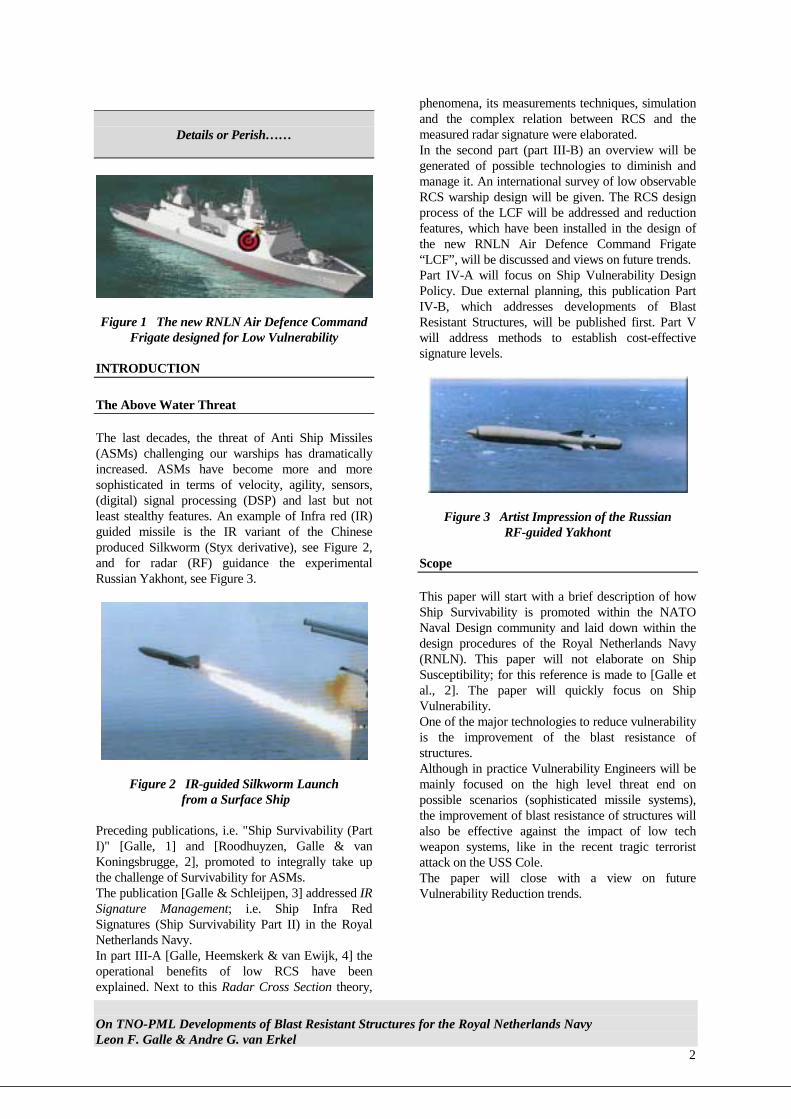
Figure 1 The new RNLN Air Defence Command
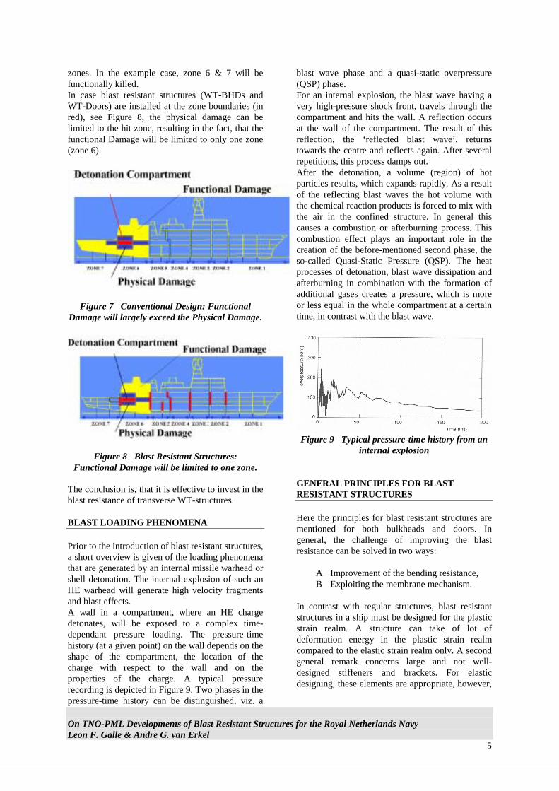
Frigate designed for Low Vulnerability INTRODUCTION The Above Water Threat The last decades, the threat of Anti Ship Missiles (ASMs) challenging our warships has dramatically increased. ASMs have become more and more sophisticated in terms of velocity, agility, sensors, (digital) signal processing (DSP) and last but not least stealthy features. An example of Infra red (IR) guided missile is the IR variant of the Chinese produced Silkworm (Styx derivative), see Figure 2, and for radar (RF) guidance the experimental Russian Yakhont, see Figure 3.
Figure 2 IR-guided Silkworm Launch from a Surface Ship
Preceding publications, i.e. "Ship Survivability (Part I)" [Galle, 1] and [Roodhuyzen, Galle & van Koningsbrugge, 2], promoted to integrally take up the challenge of Survivability for ASMs. The publication [Galle & Schleijpen, 3] addressed IR Signature Management; i.e. Ship Infra Red Signatures (Ship Survivability Part II) in the Royal Netherlands Navy. In part III-A [Galle, Heemskerk & van Ewijk, 4] the operational benefits of low RCS have been explained. Next to this Radar Cross Section theory,
phenomena, its measurements techniques, simulation and the complex relation between RCS and the measured radar signature were elaborated. In the second part (part III-B) an overview will be generated of possible technologies to diminish and manage it. An international survey of low observable RCS warship design will be given. The RCS design process of the LCF will be addressed and reduction features, which have been installed in the design of the new RNLN Air Defence Command Frigate “LCF”, will be discussed and views on future trends. Part IV-A will focus on Ship Vulnerability Design Policy. Due external planning, this publication Part IV-B, which addresses developments of Blast Resistant Structures, will be published first. Part V will address methods to establish cost-effective signature levels.
Figure 3 Artist Impression of the Russian RF-guided Yakhont
Scope This paper will start with a brief description of how Ship Survivability is promoted within the NATO Naval Design community and laid down within the design procedures of the Royal Netherlands Navy (RNLN). This paper will not elaborate on Ship Susceptibility; for this reference is made to [Galle et al., 2]. The paper will quickly focus on Ship Vulnerability. One of the major technologies to reduce vulnerability is the improvement of the blast resistance of structures. Although in practice Vulnerability Engineers will be mainly focused on the high level threat end on possible scenarios (sophisticated missile systems), the improvement of blast resistance of structures will also be effective against the impact of low tech weapon systems, like in the recent tragic terrorist attack on the USS Cole. The paper will close with a view on future Vulnerability Reduction trends.

On TNO-PML Developments of Blast Resistant Structures for the Royal Netherlands Navy Leon F. Galle & Andre G. van Erkel
3
Engineering for Survivability Warships are designed, procured and operated to perform a mission like e.g. Anti Submarine Warfare (ASW), Anti Air Warfare (AAW), Tactical Ballistic Missile Defence (TBMD) or Embargo. In most of these missions the warship will have to act under (man-made) threat conditions. This is the essence of a warship’s capability. Missions can only be successfully executed, if the warship can survive such a hostile environment. Mission Effectiveness is in principle a conditional situation; i.e. under the condition that the ship survives. Figure 4 shows the essential relation between Mission Effectiveness and Survivability.
Figure 4 The conditional relation between Mission Effectiveness & Survivability
Two Survivability factors; Susceptibility and Vulnerability, according to NATO nomenclature, were explained in [Roodhuyzen et al., 1], see Figure 5. Susceptibility; being the inability to avoid weapon effects and Vulnerability; the inability of the warship to withstand weapon effects.
OPERATIONALASPECTS
DESIGNASPECTS
MAXIMISERECOVERABILITY
MINIMISEDAMAGE
RESISTWEAPON EFFECTS
HARDKILL
SOFTKILL
PREVENT/DELAYOWN DETECTION
HIT / FUSE POINTMANAGEMENT
SUSCEPTIBILITY
VULNERABILITY
SURVIVABILITY
DETECTTHREAT
Figure 5 Generic Ship Survivability Scheme
VULNERABILITY REDUCTION
Vulnerability Reduction Measures have to be balanced with the Susceptibility Measures. Warships have different possibilities to avoid a hit (i.e. HK, SK Defence & Signature Management), see Figure 5. These susceptibility technologies have to be applied in a cost-effective way to reduce the risk of a hit. However, the importance of vulnerability reduction for warships cannot be stressed hard enough. Susceptibility measures can never eliminate the probability of a hit with its successive loss of live, casualties, loss of mission and materiel, will it be caused either by be a high tech (like e.g. latest generation of missile systems) or a low tech (like e.g. terrorist attack) threat. Survivability, often a misunderstood concept, came under question, after the dramatic experiences of the Israeli Frigate “Eilat” attacked by “Styx”-missiles in the Yom Kippur War and later for western navy warships, after the experiences in the Falklands and the Persian Gulf (USS Stark). In the Falklands 16 frigates (e.g. HMS Sheffield) and destroyers were hit of the 23 engaged in battle actions (70 %). Moreover, the only recorded interceptions of (outdated) ASMs by HK weapons were by HMS Gloucester in the "Second" Gulf war. As operations in littoral areas (brown waters) become more likely, it is expected that our warships will be at even higher risk. Therefore, the effect of a weapon hit should be taken into account in a warship's design. For a frigate-sized ship, the threatening conventional weapons comprise torpedoes, mines, shaped charges ARMs and ASMs with fragmentation and blast warheads. Non-conventional threats are nuclear, chemical and biological weapons. In this paper, the emphasis is on the conventional High Explosive (HE) missile warhead detonation of an ASM. The primary damage phenomena of the conventional weapons are penetration by fragments, blast, penetration and shock. Secondary phenomena, developing after the primary effects, which threaten the ship are fire and flooding, see Figure 6.
On TNO-PML Developments of Blast Resistant Structures for the Royal Netherlands Navy Leon F. Galle & Andre G. van Erkel
4
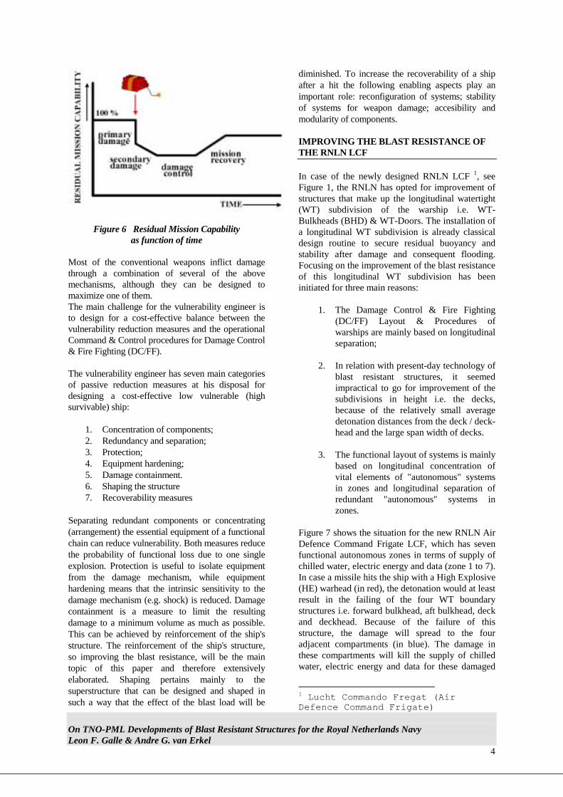
Figure 6 Residual Mission Capability as function of time
Most of the conventional weapons inflict damage through a combination of several of the above mechanisms, although they can be designed to maximize one of them. The main challenge for the vulnerability engineer is to design for a cost-effective balance between the vulnerability reduction measures and the operational Command & Control procedures for Damage Control & Fire Fighting (DC/FF). The vulnerability engineer has seven main categories of passive reduction measures at his disposal for designing a cost-effective low vulnerable (high survivable) ship:
1. Concentration of components; 2. Redundancy and separation; 3. Protection; 4. Equipment hardening; 5. Damage containment. 6. Shaping the structure 7. Recoverability measures
Separating redundant components or concentrating (arrangement) the essential equipment of a functional chain can reduce vulnerability. Both measures reduce the probability of functional loss due to one single explosion. Protection is useful to isolate equipment from the damage mechanism, while equipment hardening means that the intrinsic sensitivity to the damage mechanism (e.g. shock) is reduced. Damage containment is a measure to limit the resulting damage to a minimum volume as much as possible. This can be achieved by reinforcement of the ship's structure. The reinforcement of the ship's structure, so improving the blast resistance, will be the main topic of this paper and therefore extensively elaborated. Shaping pertains mainly to the superstructure that can be designed and shaped in such a way that the effect of the blast load will be
diminished. To increase the recoverability of a ship after a hit the following enabling aspects play an important role: reconfiguration of systems; stability of systems for weapon damage; accesibility and modularity of components. IMPROVING THE BLAST RESISTANCE OF THE RNLN LCF In case of the newly designed RNLN LCF 1, see Figure 1, the RNLN has opted for improvement of structures that make up the longitudinal watertight (WT) subdivision of the warship i.e. WT-Bulkheads (BHD) & WT-Doors. The installation of a longitudinal WT subdivision is already classical design routine to secure residual buoyancy and stability after damage and consequent flooding. Focusing on the improvement of the blast resistance of this longitudinal WT subdivision has been initiated for three main reasons:
1. The Damage Control & Fire Fighting (DC/FF) Layout & Procedures of warships are mainly based on longitudinal separation;
2. In relation with present-day technology of
blast resistant structures, it seemed impractical to go for improvement of the subdivisions in height i.e. the decks, because of the relatively small average detonation distances from the deck / deck-head and the large span width of decks.
3. The functional layout of systems is mainly
based on longitudinal concentration of vital elements of "autonomous" systems in zones and longitudinal separation of redundant "autonomous" systems in zones.
Figure 7 shows the situation for the new RNLN Air Defence Command Frigate LCF, which has seven functional autonomous zones in terms of supply of chilled water, electric energy and data (zone 1 to 7). In case a missile hits the ship with a High Explosive (HE) warhead (in red), the detonation would at least result in the failing of the four WT boundary structures i.e. forward bulkhead, aft bulkhead, deck and deckhead. Because of the failure of this structure, the damage will spread to the four adjacent compartments (in blue). The damage in these compartments will kill the supply of chilled water, electric energy and data for these damaged
1 Lucht Commando Fregat (Air Defence Command Frigate)
On TNO-PML Developments of Blast Resistant Structures for the Royal Netherlands Navy Leon F. Galle & Andre G. van Erkel
5
zones. In the example case, zone 6 & 7 will be functionally killed. In case blast resistant structures (WT-BHDs and WT-Doors) are installed at the zone boundaries (in red), see Figure 8, the physical damage can be limited to the hit zone, resulting in the fact, that the functional Damage will be limited to only one zone (zone 6).
Figure 7 Conventional Design: Functional Damage will largely exceed the Physical Damage.
Figure 8 Blast Resistant Structures: Functional Damage will be limited to one zone.
The conclusion is, that it is effective to invest in the blast resistance of transverse WT-structures. BLAST LOADING PHENOMENA Prior to the introduction of blast resistant structures, a short overview is given of the loading phenomena that are generated by an internal missile warhead or shell detonation. The internal explosion of such an HE warhead will generate high velocity fragments and blast effects. A wall in a compartment, where an HE charge detonates, will be exposed to a complex time-dependant pressure loading. The pressure-time history (at a given point) on the wall depends on the shape of the compartment, the location of the charge with respect to the wall and on the properties of the charge. A typical pressure recording is depicted in Figure 9. Two phases in the pressure-time history can be distinguished, viz. a
blast wave phase and a quasi-static overpressure (QSP) phase. For an internal explosion, the blast wave having a very high-pressure shock front, travels through the compartment and hits the wall. A reflection occurs at the wall of the compartment. The result of this reflection, the ‘reflected blast wave’, returns towards the centre and reflects again. After several repetitions, this process damps out. After the detonation, a volume (region) of hot particles results, which expands rapidly. As a result of the reflecting blast waves the hot volume with the chemical reaction products is forced to mix with the air in the confined structure. In general this causes a combustion or afterburning process. This combustion effect plays an important role in the creation of the before-mentioned second phase, the so-called Quasi-Static Pressure (QSP). The heat processes of detonation, blast wave dissipation and afterburning in combination with the formation of additional gases creates a pressure, which is more or less equal in the whole compartment at a certain time, in contrast with the blast wave.
Figure 9 Typical pressure-time history from an
internal explosion GENERAL PRINCIPLES FOR BLAST RESISTANT STRUCTURES Here the principles for blast resistant structures are mentioned for both bulkheads and doors. In general, the challenge of improving the blast resistance can be solved in two ways:
A Improvement of the bending resistance, B Exploiting the membrane mechanism.
In contrast with regular structures, blast resistant structures in a ship must be designed for the plastic strain realm. A structure can take of lot of deformation energy in the plastic strain realm compared to the elastic strain realm only. A second general remark concerns large and not well-designed stiffeners and brackets. For elastic designing, these elements are appropriate, however,

On TNO-PML Developments of Blast Resistant Structures for the Royal Netherlands Navy Leon F. Galle & Andre G. van Erkel
6
for large blast loadings they often cause cracks and as a consequence premature failure of the element. When use is made of the bending resistance, the blast forces are taken by the internal bending moments, which is the usual mechanism for many structures. To increase the bending resistance of structures, mass must be added in a conventional way, resulting in rather stiff and heavy structures that can withstand only moderate pressures. To comply with the requirement of withstanding the blast effects in the explosion compartment, membrane structures are more suitable for an acceptable mass penalty. The membrane mechanism is based on stretching a plate due to large deflections by preventing the in-plane movement of the edges of the plate (bulkhead or door). When the plate is loaded up to its maximum tensile strength the resistance of the bulkhead increases linear with its mid-deflection. The objective of the panel-designer is to find measures, which allow the highest possible deflection without failure of the panel. Designing in this way is unconventional as large reaction forces arise and a flexible connection to the regular ship structure is necessary. In this paper the focus will be on structures based on the membrane mechanism although also structures are presented based on the bending mechanism. Not all locations in the ship allow a membrane-based structure to be applied. For instance, bulkheads with no adjacent bulkheads above and beneath show a lack of in plane resistance and are less suitable for the membrane mechanism. In such cases it is inevitable to use both mechanisms (bending and membrane) for designing a blast resistant structure. Blast improvement measures aim to avoid exceeding a critical level of local strain in the panel but particularly near the weld, see Figure 10. So, locations of strain concentrations must be avoided. The strain at these locations must be balanced to obtain a balanced concept. The acceptable local strain level is determined from experiments and theoretical research. PML and the University of Delft are performing a PhD study on this subject. Note that as a result of fragment holes the allowable strain level can be much lower than for an unperforated plate.
Figure 10 High Stress and Strain at the BHD & Deck connection
Due to the curvature of the panel a plastic hinge is formed at the edge-deck connection. The tensile force from the membrane mechanism tends to concentrate this plastic hinge and hence increases the local strain at the main horizontal welds at the top and bottom of the bulkhead. Three principles are available to cope with a plastic hinge at this location: 1) Avoid a weld at the critical location to allow a
large strain; 2) Take the part of the bulkhead connected to the
deck of higher thickness to keep the ratio of the tensile force capacity of the middle plate over the capacity of this lower part below one.
3) Force the critical part of the bulkhead to follow a smooth part in order to spread the strain.
All three principles can be used for blast resistant structures. In general one can say that detailing the edge-deck connection for blast resistant bulkheads and the doorframe connection for doors, keeps the principle for obtaining an efficient design. LEVELS OF PROTECTION Roughly speaking two levels of blast resistance can be distinguished. I Bulkheads and doors which must be able to
resist the direct blast effects of a relatively small HE charge, or be able to withstand the venting pressure in a compartment adjacent to the explosion compartment. In some cases structures based on the bending mechanism can comply with this requirement.
II Bulkheads and doors, which must be able to resist the blast effects in the explosion,

On TNO-PML Developments of Blast Resistant Structures for the Royal Netherlands Navy Leon F. Galle & Andre G. van Erkel
7
compartment for larger HE charges. For this requirement the membrane mechanism have to be applied or possibly a combination of bending and membrane.
The optimal (balanced) level of the blast resistance of a door will be to design it for the same level of blast resistance as the WT-BHD in which the door will be installed (matched design). Two blast resistant doors (level I and II) and three blast resistant bulkhead concepts (level I and II) are dealt with now. BLAST RESISTANT DOOR FOR CONVENTIONAL WT-BULKHEADS Level I Shortfall Conventional Doors The most vulnerable link of "blast resistance" in the longitudinal watertight subdivision of conventional ship designs is Watertight (WT) doors. Conventional WT doors are only tested and classified for static water pressure in flooded conditions. They are not classified for the highly dynamic loadings as result of blast effects. The result of this fact is, that conventional WT-doors will fail at very low internal explosion levels. This fact has been proven during the RNLN / TNO-PML "Roofdier-Trials" on decommissioned RNLN frigates of the Roofdier class. Even an internal detonation of a medium sized naval shell was able to blow out a large number of WT-doors over a long corridor distance, see Figure 11. Exposing all involved compartments (personnel & materiel!), to overpressures and freeing the consequent spread of fire, smoke and water. The first step to improve the blast resistance of the longitudinal subdivision is by improving the blast resistance of the WT-Doors. Blast requirements of conventional WT-Doors Through failed elements like bulkheads and doors, the high pressure in the explosion compartment vents into the adjacent compartment, causing a pressure rise there. When this venting process is very rapid, compression waves arise which – in case of venting into small volumes like passageways – have a high destructive potential. The expansion of compression wave in a passage way (i.e. pressure decrease) is small, which results in a focussing effect, called ‘jetting’
Figure 11 A Roofdier Trial Result; WT-doors taken out by the detonation of a
medium sized naval shell. Especially for the load on doors in these passageways, this jetting effect plays an important role. An estimate of a typical load on a door in the adjacent compartment has been made with the aid of experimental results where the jetting effect occurred. This characteristic blast load was used as requirement for doors in conventional bulkheads. Principals of Improvement for Blast Resistance WT-Doors The relatively low blast resistance of conventional WT ship doors, based on the bending mechanism, is depicted in Figure 12. Already at low loading levels the doorplate will show a large mid deflection, particularly distortions of the doorframe. Because of the axial shortening (inplane movement) of the door, the door in itself will, at low loading levels, "pop" through the frame.

On TNO-PML Developments of Blast Resistant Structures for the Royal Netherlands Navy Leon F. Galle & Andre G. van Erkel
8
Figure 12 Failure mechanism of conventional
doors Solutions for possible improvements of these bending based designs can be divided into two categories. The first one deals with a loading direction against the frame and the second with a loading direction away from the frame. For a loading against the frame (see Figure 12b) the frame length and the nearest stiffener must be designed properly as well as the edge of the frame. For loading away from the door edge, the latches revealed to be the weakest part of the door (Figure 12c) and the designer must have a look at (the shafts of) the latches. Experimental Validation and Application of design In close concert with the RNLN, TNO-PML and a door manufacturer (Van Dam2 BV), an existing design has been improved based on the above-mentioned considerations. This door has experimentally been validated, with the defined dynamic loading, under a German - Netherlands Naval Cooperation Program (Figure 13). Doors of this type have been procured by the RNLN and will be installed at all positions where use is made of conventional bulkhead structure design on board the new RNLN LCF.
2 Fabriek van Plaatwerken Van Dam BV
Figure 13 A level I door in its test frame BLAST & FRAGMENT RESISTANT PRIMA WT-BULKHEADS Level II Shortfall Conventional WT-Bulkheads Watertight bulkheads, which are designed with conventional procedures, will not be able to resist the loadings of a missile warhead detonation, in case they are exposed to the blast effects in the explosion compartment. Bulkheads adjacent to the explosion compartment might also fail depending on the charge mass and the location of the bulkhead. Figure 14 depicts a bulkhead failed at the lower deck-connection and rotated around the deckhead into the adjacent compartment.
Figure 14 Failed conventional WT Bulkhead during the Roofdier Trials
Ship doorsShip doorsShip doors
a. Normal closed condition
b. Response mechanism when loadedagainst the frame
c. Response mechanism when loadedaway from the frame
frame length

On TNO-PML Developments of Blast Resistant Structures for the Royal Netherlands Navy Leon F. Galle & Andre G. van Erkel
9
As explained earlier, to improve the blast resistance of the bulkhead, the connections between BHD and Deck / Deckhead had to be redesigned and if possible, the membrane mechanism must be exploited. Design for Blast Resistance WT-Bulkheads A double bulkhead was designed, called the Prima Double Bulkhead, based on the membrane mechanism. The double plating was put on a small horizontal part, which was connected to a slender insert plate, see Figure 15.
Slender insert plate
Figure 15 The Principals of the Blast & Fragment Resistant PriMa Bulkhead
To cope with the plastic hinge at the deck connection the slender insert plate was carefully designed with FEM calculations based on LsDyna And Abaqus, see Figure 16.
Figure 16 FEM calculations on the PDB PriMa bulkheads present a high probability of survival against missile warhead detonation; thus preventing blast and fragments from propagating into and killing the next autonomous zone. This was shown with the in house developed internal blast code DAMINEX, [Erkel et al 6]. A large number of explosion positions were simulated where the outcome of the FEM calculations was used as failure criterion.
The bulkhead was also thoroughly designed to be able to meet the operational requirements for flooding, buckling and fatigue, see Figure 17.
98-051 2798-101
PriMa Double BulkheadPriMa Double PriMa Double BulkheadBulkhead
Figure 17 A schematic view of the PDB in the ship environment The blast resistance of the PriMa bulkheads will be compromised by penetrations of piping and cables systems, see Figure 19. This compromise has already been minimized, by decreasing the number of necessary penetrations, through concentration of system elements in one zone or even a compartment. However where penetrations cannot be avoided, the insert plate element of the PriMa bulkhead is compensated in thickness. Experimental Validation and Application A PriMa bulkhead has been successfully tested in cooperation with DERA3, Dunfermline, see Figure 18.
Figure 18 Experimental Validation under UK-NL Cooperation Program - DERA BTF Test
PriMa BHDs are installed at the zone boundaries at the RNLN LCF and at positions were special functions have to be protected, see Figure 19.
3 Defence Evaluation and Research Agency
On TNO-PML Developments of Blast Resistant Structures for the Royal Netherlands Navy Leon F. Galle & Andre G. van Erkel
10
Figure 19 Application of PriMa BHDs o/b the RNLN LCF
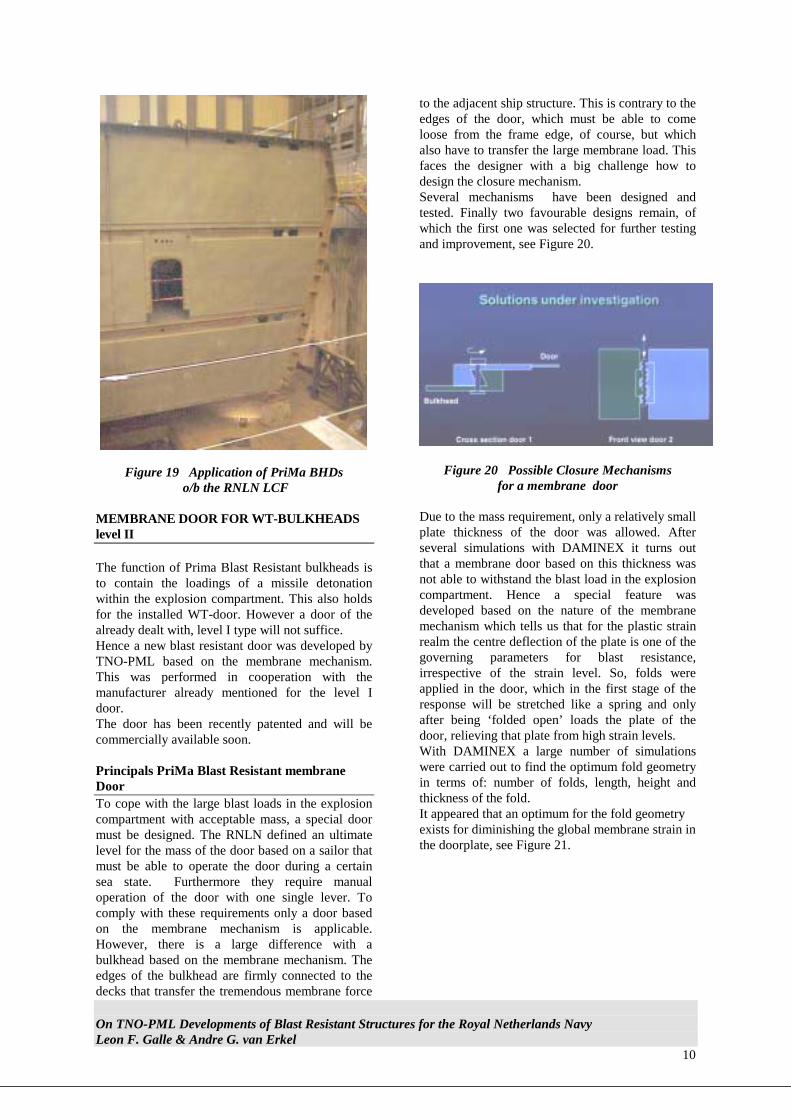
MEMBRANE DOOR FOR WT-BULKHEADS level II The function of Prima Blast Resistant bulkheads is to contain the loadings of a missile detonation within the explosion compartment. This also holds for the installed WT-door. However a door of the already dealt with, level I type will not suffice. Hence a new blast resistant door was developed by TNO-PML based on the membrane mechanism. This was performed in cooperation with the manufacturer already mentioned for the level I door. The door has been recently patented and will be commercially available soon. Principals PriMa Blast Resistant membrane Door To cope with the large blast loads in the explosion compartment with acceptable mass, a special door must be designed. The RNLN defined an ultimate level for the mass of the door based on a sailor that must be able to operate the door during a certain sea state. Furthermore they require manual operation of the door with one single lever. To comply with these requirements only a door based on the membrane mechanism is applicable. However, there is a large difference with a bulkhead based on the membrane mechanism. The edges of the bulkhead are firmly connected to the decks that transfer the tremendous membrane force
to the adjacent ship structure. This is contrary to the edges of the door, which must be able to come loose from the frame edge, of course, but which also have to transfer the large membrane load. This faces the designer with a big challenge how to design the closure mechanism. Several mechanisms have been designed and tested. Finally two favourable designs remain, of which the first one was selected for further testing and improvement, see Figure 20.
Figure 20 Possible Closure Mechanisms for a membrane door
Due to the mass requirement, only a relatively small plate thickness of the door was allowed. After several simulations with DAMINEX it turns out that a membrane door based on this thickness was not able to withstand the blast load in the explosion compartment. Hence a special feature was developed based on the nature of the membrane mechanism which tells us that for the plastic strain realm the centre deflection of the plate is one of the governing parameters for blast resistance, irrespective of the strain level. So, folds were applied in the door, which in the first stage of the response will be stretched like a spring and only after being ‘folded open’ loads the plate of the door, relieving that plate from high strain levels. With DAMINEX a large number of simulations were carried out to find the optimum fold geometry in terms of: number of folds, length, height and thickness of the fold. It appeared that an optimum for the fold geometry exists for diminishing the global membrane strain in the doorplate, see Figure 21.
On TNO-PML Developments of Blast Resistant Structures for the Royal Netherlands Navy Leon F. Galle & Andre G. van Erkel
11
moderate charge at moderate distance;one fold at each side;
width of passage way is 1.8 m with 6 mm bulkhead.
1
2
3
4
5
6
7
8
9
0 10 20 30 40 50 60 70 80height of fold [mm]
glob
al m
embr
ane
stra
in [%
]
tf =8 mm, FL=40mm
tf =10 mm, FL=40mm
tf =10 mm, FL=30mm
tf =8 mm, FL=30mm
Figure 21 The effect of various fold geometries on the membrane strain
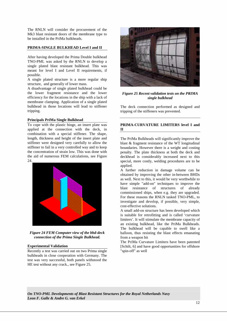
Experimental Validation and Application The membrane door has experimentally been validated in the TNO test facility with parts of the mechanism. In 1999 PriMa-door Mk2 has been tested in a large ship section in close cooperation with DERA (UK). The door endured all tests satisfactorily.
Figure 22 The Prima Membrane Mk3 door in the DERA Blast Test box (Pre Trial).
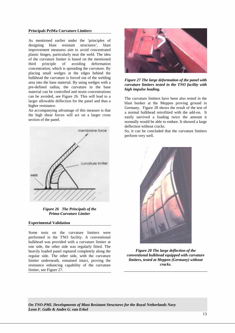
In December 2000, a final qualification blast test has been performed on the Mk3 design for the very high loading conditions of level II, see Figure 22 & 23. The Mk3 design passed the qualification blast test. The door deflected introducing membrane strain of the doorplate and unfolding of the folds and survived the explosion without any significant cracks or fractures.
Figure 23 The Prima Membrane Mk3 door in the DERA Blast Test box (Post Trial).
On TNO-PML Developments of Blast Resistant Structures for the Royal Netherlands Navy Leon F. Galle & Andre G. van Erkel
12
The RNLN will consider the procurement of the Mk3 blast resistant doors of the membrane type to be installed in the PriMa bulkheads. PRIMA-SINGLE BULKHEAD Level I and II After having developed the Prima Double bulkhead TNO-PML was asked by the RNLN to develop a single plated blast resistant bulkhead. This was meant for level I and Level II requirements, if possible. A single plated structure is a more regular ship structure, and generally of lower mass. A disadvantage of single plated bulkhead could be the lower fragment resistance and the lower efficiency for the locations in the ship with a lack of membrane clamping. Application of a single plated bulkhead in those locations will lead to stiffener tripping. Principals PriMa Single Bulkhead To cope with the plastic hinge, an insert plate was applied at the connection with the deck, in combination with a special stiffener. The shape, length, thickness and height of the insert plate and stiffener were designed very carefully to allow the stiffener to fail in a very controlled way and to keep the concentration of strain low. This was done with the aid of numerous FEM calculations, see Figure 24.
Figure 24 FEM Computer view of the bhd-deck connection of the Prima Single Bulkhead.
Experimental Validation Recently a test was carried out on two Prima single bulkheads in close cooperation with Germany. The test was very successful, both panels withstood the HE test without any crack., see Figure 25.
Figure 25 Recent validation tests on the PRIMA
single bulkhead The deck connection performed as designed and tripping of the stiffeners was prevented. PRIMA-CURVATURE LIMITERS level I and II The PriMa Bulkheads will significantly improve the blast & fragment resistance of the WT longitudinal boundaries. However there is a weight and costing penalty. The plate thickness at both the deck and deckhead is considerably increased next to this special, more costly, welding procedures are to be applied. A further reduction in damage volume can be obtained by improving the other in-between BHDs as well. Next to this, it would be very worthwhile to have simple "add-on" techniques to improve the blast resistance of structures of already commissioned ships, when e.g. they are upgraded. For these reasons the RNLN tasked TNO-PML, to investigate and develop, if possible, very simple, cost-effective solutions. A small add-on structure has been developed which is suitable for retrofitting and is called ‘curvature limiters’. It will stimulate the membrane capacity of an existing bulkhead, like the PriMa Bulkheads. The bulkhead will be capable to swell like a balloon, thus resisting the blast effects emanating from a weapon hit The PriMa Curvature Limiters have been patented [Schilt, 6] and have good opportunities for offshore "spin-off" as well
On TNO-PML Developments of Blast Resistant Structures for the Royal Netherlands Navy Leon F. Galle & Andre G. van Erkel
13
Principals PriMa Curvature Limiters As mentioned earlier under the ‘principles of designing blast resistant structures’, blast improvement measures aim to avoid concentrated plastic hinges, particularly near the weld. The idea of the curvature limiter is based on the mentioned third principle of avoiding deformation concentration; which is spreading the curvature. By placing small wedges at the edges behind the bulkhead the curvature is forced out of the welding area into the base material. By using wedges with a pre-defined radius, the curvature in the base material can be controlled and strain concentrations can be avoided, see Figure 26. This will lead to a larger allowable deflection for the panel and thus a higher resistance. An accompanying advantage of this measure is that the high shear forces will act on a larger cross section of the panel.
Figure 26 The Principals of the Prima-Curvature Limiter
Experimental Validation Some tests on the curvature limiters were performed in the TNO facility. A conventional bulkhead was provided with a curvature limiter at one side, the other side was regularly fitted. The heavily loaded panel ruptured completely along the regular side. The other side, with the curvature limiter underneath, remained intact, proving the resistance enhancing capability of the curvature limiter, see Figure 27.
Figure 27 The large deformation of the panel with curvature limiters tested in the TNO facility with high impulse loading. The curvature limiters have been also tested in the blast bunker at the Meppen proving ground in Germany. Figure 28 shows the result of the test of a normal bulkhead retrofitted with the add-on. It easily survived a loading twice the amount it normally would be able to endure. It showed a large deflection without cracks. So, it can be concluded that the curvature limiters perform very well.
Figure 28 The large deflection of the conventional bulkhead equipped with curvature limiters, tested at Meppen (Germany) without
cracks.

On TNO-PML Developments of Blast Resistant Structures for the Royal Netherlands Navy Leon F. Galle & Andre G. van Erkel
14
FUTURE TRENDS So far, only the improvement of the Blast Resistance of structures has been dealt with. However, dealing with the problem, can also be performed from an other starting point; Manipulating the loading, see Figure 29. Explosion suppression
Figure 29 The Principal Function of Explosion Suppression
In case a vulnerability engineer has the technology at his disposal to manipulate the loading, he could also match the blast resistance of his structure in order to come up with a more cost-effective solution. Trials were conducted to analyse the mitigation of the blast effects by using a mist of water spray in the explosion compartment. Until now it could be concluded that there is a reduction of the pressure, more trials will follow in the near future. Figure 30 gives a general design curve of matching the blast resistance with the pressure load mitigated by water mist.
Figure 30 Matching the Blast Resistance with the Loading
CONCLUSION / DISCUSSION The importance of vulnerability reduction for warships has been stressed. Warships have various possibilities to avoid a hit (i.e. HK, SK & Signature Management). These susceptibility technologies have to be applied in a cost-effective way to reduce the risk of a hit. However, they can never eliminate
the probability of a hit with its successive loss of lives, casualties, loss of mission and materiel, will it be caused either by be a high tech or a low tech threat. Therefore vulnerability reduction technologies have to be incorporated in the design of fighting platforms. Improving the blast resistance of structures has proven to be one of the cost-effective solutions. The RNLN, in concert with TNO-PML, has been focusing on the reduction of the longitudinal spread of damage after an internal detonation, thus improving the blast-resistance of longitudinal watertight subdivisions (i.e. bulkheads and doors). Two blast resistant doors and three blast resistant bulkhead concepts have been presented for two levels of requirement. All concepts have been validated by experiments. Both door designs and the double bulkhead design will be applied in the new Dutch LCF frigate. The development and validation of these concepts was also founded on successful international co-operation, especially with the German and British Naval Defence communities.
ACKNOWLEDGEMENTS The authors acknowledge the Department of Naval Architecture and Marine Engineering (MarTech), Directorate of the Materiel of the Royal Netherlands Navy and the Prins Maurits Laboratory (TNO-PML) of the Netherlands Organisation for Applied Scientific Research for putting data and pictures at our disposal.
Water mitigation
Resistance of structure
Pres
sure
Water mass / Explosive mass

On TNO-PML Developments of Blast Resistant Structures for the Royal Netherlands Navy Leon F. Galle & Andre G. van Erkel
15
ABBREVIATIONS AAW Anti Air Warfare ADCF Air Defence Command Frigate (RNLN) ASM Anti Ship Missile ARM Anti Radiation Missile ASW Anti Submarine Warfare ASuW Anti Surface Warfare AW Above Water BHD Bulkhead BR Blast Resistant CIWS Close In Weapon System DC Damage Control DSP Digital Signal Processing DOF Degree of Freedom ESSM Evolved Seasparrow Missile FEL Physics and Electronics Laboratory FF Fire Fighting HE High Explosive HK Hard Kill LCC Life Cycle Costing LCF Luchtverdediging en Commando Fregat (RNLN) MoE Measures of Effectiveness NSSM Nato Seasparrow Missile PML Prins Maurits Laboratory (TNO) QSP Quasi Static Pressure RNLN Royal Netherlands Navy SCC Ship’s Control Centre SK Soft Kill SM Standard Missile TBMD Tactical Ballistic Missile Defence TNO Netherlands Organisation for Applied Scientific Research WT Water Tight REFERENCES [1] Galle, Leon F. The Impact of Platform Design on Ship Survivability,
part I (Features of the new RNLN Air Defence Command Frigate), Marineblad, 1997.
[2] Roodhuyzen P.J., Galle, L.F. & van Koningsbrugge, A.J.J.M.
The Survivability Frigate; The new RNLN Air Defence Command Frigate Presented at International Maritime EXhibition and Symposium IMDEX 1997, Greenwich, UK
[3] Galle, L. F. & Schleijpen, R.M.A. Ship Infra Red (IR) Signatures Ship Survivability, part II (Features of the new RNLN Air Defence Command Frigate), Marineblad, 1998. [4] Galle, L.F., Heemskerk H.J.M & Ewijk L.J. Warship Radar Signatures Ship Survivability, part III-A (Features of the new
RNLN Air Defence Command Frigate), Marineblad, 2000.
[5] Erkel, A.G. van & Haverdings, W.
Simulation of internal blast inside ships and its subsequent damage analysis Presented at MABS-12, Perpignan, September 1991
[6] A. Schilt
Curvature Limiters Patented at the Dutch patents office Nederlandsch
Octrooibureau, under patent number 1013795, entitled “Explosiebestendige wandconstructie” (Explosion Resistant Wall Structure), in Dutch
BIBLIOGRAPHY [1] Rains, Dean A. Methods for Ship Military Effectiveness Analysis Naval Engineers Journal, March 1994. [2] Galle, Leon F. and Smit, Clarel S.
The Impact of Platform Design on Ship Survivability (Features of the new RNLN Air Defence Command Frigate "LCF") Presented at the Institute of Marine Engineers Conference "Warship Design: What is so Different ?" April 1996, Den Helder.
[3] Bosman T.N., Galle L.F., Keuning P.J. & Nieβen E.
Methods for the Assessment of Structural Strength of Naval Ships Presented at the 5th Int. Marine Design Conf. & Summer Meeting of the German Society of Naval Architects 1994, May 1994, Delft, The Netherlands.
[4] Erkel, A.G. van
Explosions in Ship Compartments, in Dutch, Proceedings of the “Themadag Scheepskwetsbaarheid en Roofdierproeven”, January 1991
[5] Haverdings, W. & Verheij, Z.C.
Vulnerability analysis of surface ships in the Netherlands and its experimental validation Presented at the 30th DRG Seminar on the defence of small ships against missile attacks, Ottawa, September 1990