Glenn R. Cockburn 321 Rabbit Run Lane Sewanee, Tennessee 37375 (931) 691-0631 [email protected].
Upload
truonglienCategory
view
216download
0
Lens Conventions From Jenkins & White: Fundamentals of Optics, pg 50 Incident rays travel left to right Object distance s + if left to vertex, - if right to vertex Image distance s' + if right to vertex, - if left to vertex Opposite to mirrors Focal length measured from focal point to vertex f positive for converging, negative for diverging r positive for convex surfaces r negative for concave Object and Image dimension + if up, - if down from axis

Gaussian Formula for a Spherical Surface The radius of curvature r controls the focus Gaussian Lens formula
r
nn
s
n
s
n
where n index on medium of light origin n’ index on medium entered r = radius of curvature of surface Clearly for s' infinite (parallel light output) then s = f (primary focal length)
r
nn
f
nn
s
n
nn
nrf

Thin Lens Assume that thickness is very small compared to s, s' distances This is often true for large focal length lenses Primary focus f on left convex lens, right concave Secondary focus f on right convex, left concave If same medium on both sides then thin lens approximation is
ff

Basic Thin Lens formula Basic Thin Lens formula
f
1
s
1
s
1
Lens Maker's formula for calculating f based on lens r1, r2 & n
21
111
1
rrn
f
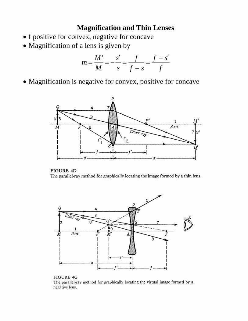
Magnification and Thin Lenses f positive for convex, negative for concave Magnification of a lens is given by
f
sf
sf
f
s
s
M
Mm
'
Magnification is negative for convex, positive for concave

Why is Light Focus by a Lens Why does the light get focused by a lens Consider a curved glass surface with index n’ on right side Radius of curvature r is centered at C Let parallel light ray P at height h from axis hit the curvature at T Normal at T is through C forming angle to parallel beam Beam is refracted by Snell’s law to angle ’ to the normal
)sin(n)sin(n
Assuming small angles then sin()~ and
n
norsin
n
n)sin(
From geometry for small angles
r
hor
r
hsin
Angle ’ the beam makes to the axis is by geometry
n
nn
r
h
n
nn
n
n
Thus the focus point is located at
nn
nr
nn
n
h
rh
h
sin
hf
Thus all light is focused at same point independent of h position This fails when small angle approx exceeded thus lens aberrations

Simple Lens Example Consider a glass (n=1.5) plano-convex lens radius r1 = 10 cm By the Lens Maker's formula
05.010
5.01
10
1)15.1(
111
1
21
rrn
f
cm.
f 20050
1
Now consider a 1 cm candle at s = 60 cm from the vertex Where is the image
fss
111
cmssfs
300333.0
1'03333.0
60
1
20
1111
Magnification 5.060
30'
s
s
M
Mm
Image at 30 cm other side of lens inverted and half object size What if candle is at 40 cm (twice f)
140
4040
05.0
1'05.0
40
1
20
1111
s
smcms
sfs
Image is at 40 cm other side of lens inverted and same size (1 cm)

Lens with Object Closer than Focus f Now place candle at 10 cm (s <f condition)
210
20
2005.0
1'05.0
10
1
20
1111
s
sm
cmssfs
Now image is on same side of lens at 20 cm (focal point) Image is virtual, erect and 2x object size Virtual image means light appears to come from it

Graphic Method of Solving Lens Optics Graphic method is why this is called Geometric Optics Use some scale (graph paper good) Place lens on axis line and mark radius C & focal F points Draw line from object top Q to lens parallel to axis (ray 4) Hits vertex line at T Then direct ray from T through focus point F and beyond Because parallel light from object is focused at f Now direct ray from object top Q through lens center (ray 5) This intersects ray 4 at image Q’ (point 7) This correctly shows both position and magnification of object This really shows how the light rays are travelling Eg Ray through the focal point F (ray 6) becomes parallel Intersects ray 5 again at image Q’

Graphical Method with Negative Lenses Same general idea as with positive lens Draw line (ray 4) from object top Q to lens parallel to axis Hits vertex line at T Now direct ray from T through focus point F on left side of lens Extend this ray beyond lens on right (ray 5) This is the diverging ray a parallel beam would make from neg lens Now direct ray from object top Q through lens center (ray 8) This intersects ray 5 at image Q’ (point 9) Virtual Image is now to right and is erect & smaller This is where and eye on the right would see the object Graphics methods great for quick understanding of optics systems Really good for understanding what happens in multi-lens optics

Thin Lens Principal Points Object and image distances are measured from the Principal Points Secondary principal point H” location depends on the lens shape H” also depends on a thin lens orientation Note if you reverse a lens it often does not focus at the same point Only symmetric lens shapes have symmetric principal & focal pt. Need to look at these lens specifications for principal points Note: Plano lenses when plane side toward source H” at vertex Thick lenses have separate Principal points

Thin and Thick Lens & Principal Surface Thin lens formulas work were radius of curvature is small Radius of curvature r >> than diameter Thus high F# & low light gathering power When lens has radius of curvature 2 or 3 times diameter then thick Now formulas must change. For biconvex/concave the thickness of centre becomes important Also now go from principal pt to principal surface Principal surface is line in lens where light appears to refract from

Thick Lens Formula Lens thickness tc (between vertex at the optical axis i.e. centre) Now lens formula much more complicated Distances measured relative to the principal points H” for light coming from the front (left) H for light coming from the back of lens (right)
21
2
21
1111
1
rr
t
n
n
rrn
fc
Note simple lens formula assumes tc = 0 which is never true But if f is large then r’s large and tc is small so good approximation Note plano-convex r2 = and fthin = fthick but principal point changes

Very Thick Lenses Now primary and secondary principal points very different A1 = front vertex (optical axis intercept of front surface) H = primary (front) principal point A2 = back vertex (optical axis intercept of back surface) H” = secondary (back) principal point tc = centre thickness: separation between vertex at optic axis Relative to the front surface the primary principal point is
21
1
r
nftHA c
Relative to the back surface the secondary principal point is
12
1
r
nftHA c
fefl effective focal length (EFL): usually different for front and back

Combining Lenses Can combine several lenses to give single lens with same effect Create a Combination Effective Focal Length fe If many thin lenses in contact (ie no space between them) then
321
1111
ffffe
Two lenses f1 and f2 separated by distance d To completely replace two lens for all calculations New image distance for object at infinity (eg laser beam)
dff
fffor
ff
d
fff ee
21
21
2121
111
Distance from first lens primary principal point to combined lens primary principal point
2f
dfD e
Distance from second lens secondary principal point to combined lens secondary principal point
1f
dfD e
Combined "thick lens" extends from D to D'

Combining Two Lens Elements Combined object distance se
Dss 1e
Combined image distance s'e
Dss 2e
NOTE: Combined object/image distance may change sign The thick lens follows the standard formula
eee f
1
s
1
s
1
Combined magnification
e
ee s
sm
Secondary focus distance relative to 2nd lens vertex is:
Dff e
Note some devices (e.g. telescopes) cannot use these formulas Reason telescopes require f1 + f2 – d = 0
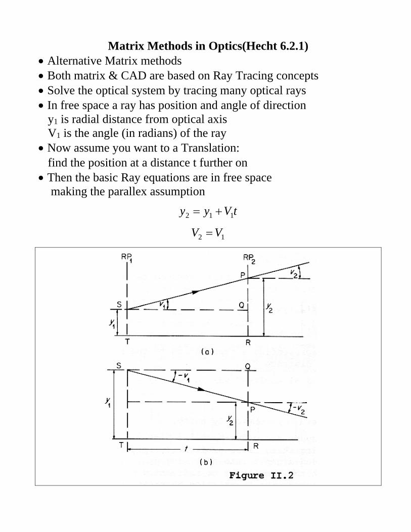
Matrix Methods in Optics(Hecht 6.2.1) Alternative Matrix methods Both matrix & CAD are based on Ray Tracing concepts Solve the optical system by tracing many optical rays In free space a ray has position and angle of direction y1 is radial distance from optical axis V1 is the angle (in radians) of the ray Now assume you want to a Translation: find the position at a distance t further on Then the basic Ray equations are in free space making the parallex assumption
tVyy 112
12 VV

Matrix Method: Translation Matrix Can define a matrix method to obtain the result for any optical process Consider a simple translation distance t Then the Translation Matrix (or T matrix)
1
1
1
1
2
2
V
y
10
t1
V
y
DC
BA
V
y
The reverse direction uses the inverse matrix
1
1
2
2
2
21
1
1
10
1
V
yt
V
y
AC
BD
V
y
DC
BA
V
y

General Matrix for Optical Devices Optical surfaces however will change angle or location Example a lens will keep same location but different angle Reference for more lens matrices & operations A. Gerrard & J.M. Burch, “Introduction to Matrix Methods in Optics”, Dover 1994 Matrix methods equal Ray Trace Programs for simple calculations

General Optical Matrix Operations Place Matrix on the left for operation on the right Can solve or calculate a single matrix for the system
1
1
2
2
V
yMMM
V
yobjectlensimage
1
1
2
2
10
11
101
10
1
V
ys
f
s
V
y

Solving for image with Optical Matrix Operations For any lens system can create an equivalent matrix Combine the lens (mirror) and spacing between them Create a single matrix
DC
BAMMMM systemn 12
Now add the object and image distance translation matrices
objectlensimagess
ss MMMDC
BA
10
s1
DC
BA
10
s1
DC
BA
ss
ss
DCsC
DCssBAsCsA
DC
BA
ss
ss
Image distance s’ is found by solving for Bs=0 Image magnification is
ss D
1m

Example Solving for the Optical Matrix Two lens system: solve for image position and size Biconvex lens f1=8 cm located 24 cm from 3 cm tall object Second lens biconcave f2= -12 cm located d=6 cm from first lens Then the matrix solution is
10
2411
8
101
10
611
12
101
10
X1
DC
BA
ss
ss
2
8
1241
2
3
12
161
10
X1
DC
BA
ss
ss
11042.0
1225.0
10
1
10
1
11
11 X
DC
BAX
DC
BA
ss
ss
ss
ss
Solving for the image position using the s1 matrix & X matrix:
cmD
BXorXDBB
s
ssss 12
1
120
1
111
Then the magnification is
11
111
1
ss DD
m
Thus the object is at 12 cm from 2nd lens, -3 cm high

Matrix Method and Spread Sheets Easy to use matrix method in Excel or matlab or maple Use mmult array function in excel Select array output cells (eg. matrix) and enter =mmult( Select space 1 cells then comma Select lens 1 cells (eg =mmult(G5:H6,I5:J6) ) Then do control+shift+enter (very important) Here is example from previous page

Optical Matrix Equivalent Lens For any lens system can create an equivalent matrix & lens Combine all the matrices for the lens and spaces The for the combined matrix
DC
BAMMMM systemn 12
Table shows how to calculate focal, nodal and principal points where RP1 = first lens left vertex RP2 = last lens right most vertex n1=index of refraction before 1st lens n2=index of refraction after last lens

Example Combined Optical Matrix Using Two lens system from before Biconvex lens f1=8 cm Second lens biconcave f2= -12 cm located 6 cm from f1 Then the system matrix is
5110420
62501
8
101
10
611
12
101
..
.
DC
BA
Second focal length (relative to H2) is
cm..C
fs 766910420
112
Second focal point, relative to RP2 (second vertex)
cm..
.
C
AfrP 4002
10420
2502
Second principal point, relative to RP2 (second vertex)
cm..
.
C
AHs 1987
10240
250112

Numerical Aperture (NA) NA is the sine of the angle the largest ray a parallel beam makes when focused
f2
sinNA
where = angle of the focused beam = diameter of the lens NA <1 are common High NA lenses are faster lenses NA is related to the F#
NA#F
2
1

Human Eye Human eye is a simple single lens system Cornea: outer surface protection Aqueous humor is water like liquid behind cornea Iris: control light Crystalline lens provide focus Retina: where image is focused Note images are inverted Brain’s programming inverts the image
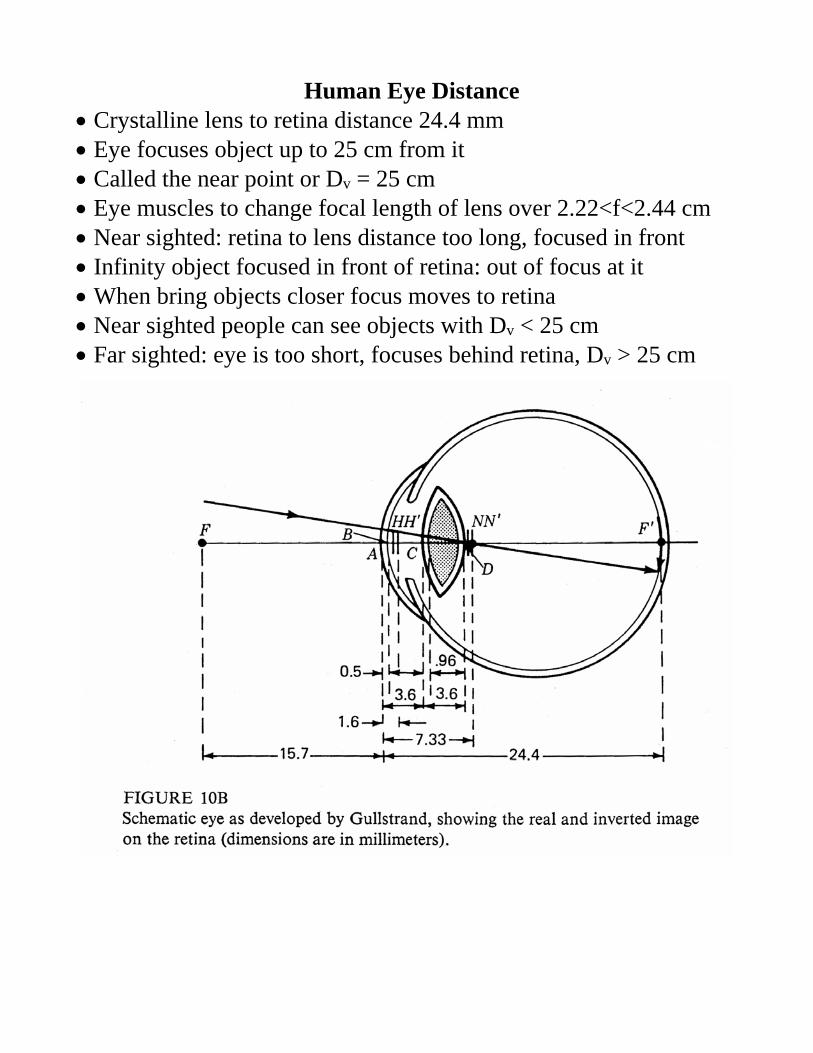
Human Eye Distance Crystalline lens to retina distance 24.4 mm Eye focuses object up to 25 cm from it Called the near point or Dv = 25 cm Eye muscles to change focal length of lens over 2.22<f<2.44 cm Near sighted: retina to lens distance too long, focused in front Infinity object focused in front of retina: out of focus at it When bring objects closer focus moves to retina Near sighted people can see objects with Dv < 25 cm Far sighted: eye is too short, focuses behind retina, Dv > 25 cm

Magnification of Lens Lateral change in distance equals change in image size Measures change in apparent image size
s
s
y
yMm
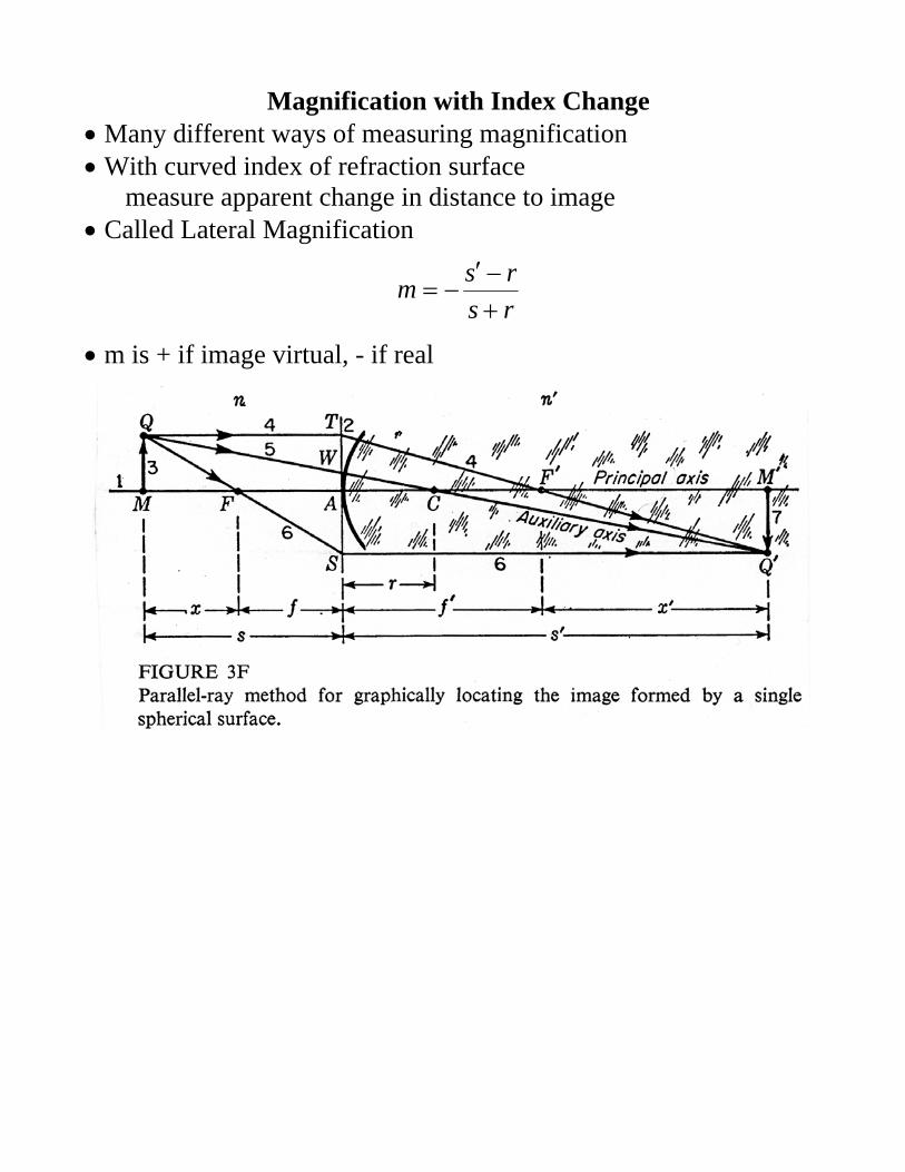
Magnification with Index Change Many different ways of measuring magnification With curved index of refraction surface measure apparent change in distance to image Called Lateral Magnification
rs
rsm
m is + if image virtual, - if real
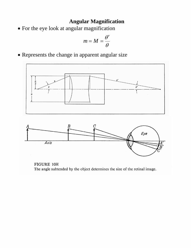
Angular Magnification For the eye look at angular magnification
Mm
Represents the change in apparent angular size

Simple Magnifying Glass Human eye focuses near point or Dv = 25 cm Magnification of object: ratio of angles at eye between unaided and lens Angle of Object with lens
25
y
D
y)tan(
v
For maximum magnification place object at lens f (in cm)
f
y
Thus magnification is (where f in cm)
fm
25
e.g. What is the magnification of a lens f = 1 inch = 2.5 cm
1052
2525
.fm

Power of a Lens or Surface Power: measures the ability to create converging/diverging light by a lens Measured in Diopters (D) or 1/m For a simple curved surface
r
nnP
For a thin lens
fP
1
Converging lens have + D, diverging - D eg f = 50 cm, D = +2 D f = -20 cm, D = -5 D Recall that for multiple lens touching
321
1111
ffffe
Hence power in Diopters is additive
21 DDD

Human Eye: A two Lens System Eye is often treated as single simple lens Actually is a two lens system Cornea with n=1.376 makes main correction Aqueous humor is nearly water index Lens n=1.406 relative to aqueous humor n causes change Eye muscles shape the lens and adjusts focus Cornea gives 44.8 D of correction Lens gives ~18.9 D of correction Cannot see in water because water index 1.33 near cornea Thus cornea correction is not there.
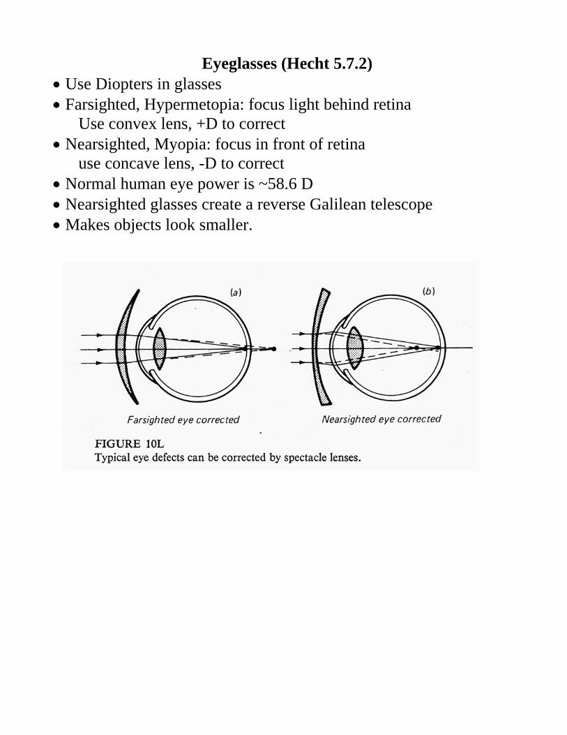
Eyeglasses (Hecht 5.7.2) Use Diopters in glasses Farsighted, Hypermetopia: focus light behind retina Use convex lens, +D to correct Nearsighted, Myopia: focus in front of retina use concave lens, -D to correct Normal human eye power is ~58.6 D Nearsighted glasses create a reverse Galilean telescope Makes objects look smaller.

Anamorphic Lenses Lenses & Mirrors do not need to be cylindrically symmetric Anamorphic Lenses have different characteristics in each axis Sphero-cylinderical most common One axis (eg vertical): cylindrical curve just like regular lens Other axis (e.g. horizontal): has no curve Result light is focused in horizontal axis but not vertical Often used to create a line of light

Astigmatism Astigmatism means light is focused in on axis not other Cylinderical lens cause as Astigmatism: focus in one plan In eyes astigmatism caused by shape of eye (& lens) Image is compressed in one axis and out of focus Typically measure D in both axis Rotation of astigmatism axis is measured Then make lens slightly cylindrical i.e. perpendicular to axis may have higher D in one than other eg. eyeglass astigmatism prescription gives +D and axis angle +D is difference between the two axis.

Ray Tracing (Hecht 6.2) For more complicated systems use CAD tools Both are based on Ray Tracing concepts Solve the optical system by tracing many optical rays Use exact surface positions & surface Do not make parallex assumption – use Snell’s law Eg.of programs Z max, Code 5, OSLO OSLO has a free limited educational version at http://www.lambdares.com/index.php/buy/educators-and-students Includes user guide at the same page