
Leica TPS800 Series -...
168
Leica TPS800 Series User Manual Version 2.1 English
Transcript of Leica TPS800 Series -...

Leica TPS800 SeriesUser Manual
Version 2.1English

Electronical Total StationCongratulations on the purchase of a TPS800 series instrument.
This manual contains important safety directions as well as instructions for setting up the product and operating it. Refer to "Safety Directions" for further information.Read carefully through the User Manual before you switch on the product.
Product identificationThe model and the serial number of your product are indicated on the type plate.Enter the model and serial number in your manual and always refer to this information when you need to contact your agency or Leica Geosystems autho-rized service workshop.
Type: ____________ Serial no.: ____________
2Leica TPS800-2.1.0en

SymbolsThe symbols used in this manual have the following meanings:
Trademarks• Windows (registered trademark of Microsoft
Corporation).• Bluetooth is a registered trademark of Bluetooth
SIG, Inc.All other trademarks are the property of their respec-tive owners.
Type Description
� Danger Indicates an imminently hazar-dous situation which, if not avoided, will result in death or serious injury.
� Warning Indicates a potentially hazardous situation or an unintended use which, if not avoided, could result in death or serious injury.
� Caution Indicates a potentially hazardous situation or an unintended use which, if not avoided, may result in minor or moderate injury and/or appreciable material, financial and environmental damage.
Important paragraphs which must be adhered to in practice as they enable the product to be used in a technically correct and efficient manner.
Type Description
3 Leica TPS800-2.1.0en

Validity of this manual
Description
General This manual applies to all TPS800 Series instruments. Where there are differences between the various models they are clearly described.
Telescope In regard to the instrument EDM, a TPS800 instrument may be equipped with one of two types of telescopes, which offer the same performance but differ in some technical details. The two different types can be distinguished by a rectangular (telescope type 1) or round (telescope type 2) shaped element, which is visible in the centre of the objective lens.Where there are technical differences between the two telescope types they are marked by the following pictograms, referring to the first or second type described above:
Telescope Type 1• When measuring distances to a reflector with EDM mode "IR" this telescope type uses
a wide infrared laser beam, which emerges coaxially from the telescope's objective.
• Instruments that are equipped with a reflectorless EDM additionally offer the EDM modes "RL" and "RL-Prism". When using these EDM modes a narrow visible red laser beam is used to measure distances.
4Leica TPS800-2.1.0en

Telescope Type 2• When measuring distances to a reflector with EDM mode "IR" this telescope type uses
a wide visible red laser beam, which emerges coaxially from the telescope's objective.
• Instruments that are equipped with a reflectorless EDM additionally offer the EDM modes "RL" and "RL-Prism". When using these EDM modes a narrow visible red laser beam is used to measure distances.
Description
5 Leica TPS800-2.1.0en

Contents - OverviewIntroduction .................................................. 10
Operating the Instrument....................... 18
Measuring Preparation / Setting up .. 26
FNC Key.......................................................... 40
Programs ....................................................... 47
Settings........................................................... 96
EDM Settings ............................................. 101
File Management ...................................... 106
Start-up sequence ................................... 109
Check & Adjust ......................................... 110
COMM Parameters .................................. 119
Data Transfer ............................................. 120
System Info................................................. 121
Instrument Protection with PIN......... 122
Care and Transport ................................. 123
Safety Directions...................................... 126
Technical Data........................................... 150
Index............................................................... 161
6Leica TPS800-2.1.0en

ContentsIntroduction .................................................. 10
Important parts............................................... 11Technical terms and abbreviations ............ 12Area of applicability....................................... 15PC Program Package Leica Geo Office Tools (LGO-Tools) ......... 15
Installation on the PC ..................................... 15Program content............................................. 15
Power Supply................................................. 17
Operating the Instrument....................... 18Keypad ............................................................ 18
Fixed keys ...................................................... 19Trigger key...................................................... 19Distance measurement ................................ 20Softkeys .......................................................... 23Symbols .......................................................... 24
Status symbol "EDM type" ............................. 24Status symbol "Battery capacity" ................... 24Status symbol "Compensator" ....................... 24Status symbol "Offset" ................................... 24Status symbol "Character Input" .................... 24
Menu tree........................................................ 25
Measuring Preparation / Setting up ... 26Unpacking....................................................... 26Batteries.......................................................... 27Setting up the tripod...................................... 29Instrument Setup........................................... 31Levelling up with the electronic level step-by-step ................................................... 33Laser intensity................................................ 34Hints for positioning ...................................... 34Input mode ..................................................... 35
Edit characters ............................................... 35Erasing characters ......................................... 35Inserting characters........................................ 35
Pointsearch .................................................... 37Wildcard search............................................. 38Measuring....................................................... 39
FNC Key.......................................................... 40Light On /Off................................................... 40Level/Plummet ............................................... 40
7 Leica TPS800-2.1.0en

IR/ RL Toggle................................................. 40Laser Pointer.................................................. 40Free-Coding ................................................... 40Units................................................................. 40Delete Last Record ....................................... 41Lock with PIN ................................................. 41Check Tie........................................................ 41Tracking .......................................................... 42Target Offset .................................................. 42Main Settings ................................................. 43Height Transfer.............................................. 44Hidden Point................................................... 45
Programs ....................................................... 47Application pre-settings................................ 47
Setting job ...................................................... 47Setting Station................................................ 48Orientation...................................................... 49
Applications .................................................... 53Introduction .................................................... 53Surveying ....................................................... 54Stake out ........................................................ 55Free Station.................................................... 57Reference Line/Arc ........................................ 63
Reference Line............................................... 63Tie Distance ................................................... 75Area & Volume ............................................... 77Remote Height ............................................... 80Construction ................................................... 812D-Road (optional)......................................... 83COGO (optional) ............................................ 87
Coding............................................................. 92Quick Code .................................................... 94
Settings........................................................... 96
EDM Settings ............................................. 101
File Management...................................... 106
Start-up sequence ................................... 109
Check & Adjust ......................................... 110Line-of-sight error (Hz-collimation)........... 111V-Index (Vertical index error) .................... 111
Tripod ........................................................... 114Circular level ................................................ 114Circular level on the tribrach ........................ 115Laser plummet ............................................. 115Chapter validity ............................................ 116Reflectorless EDM ....................................... 116
8Leica TPS800-2.1.0en

COMM Parameters .................................. 119
Data Transfer ............................................. 120
System Info ................................................. 121
Instrument Protection with PIN......... 122
Care and Transport ................................. 123Transport ...................................................... 123
Transport in the field .................................... 123Transport in a road vehicle........................... 123Shipping ....................................................... 123Shipping, transport of batteries .................... 123Field adjustment........................................... 123
Storage.......................................................... 124Product......................................................... 124Field adjustment........................................... 124Batteries ....................................................... 124
Cleaning and Drying ................................... 125Objective, eyepiece and prisms ................... 125Fogging of prisms......................................... 125Damp products............................................. 125Cables and plugs ......................................... 125
Safety Directions...................................... 126Intended Use................................................ 126
Permitted use ............................................... 126Adverse use ................................................. 126
Limits of Use ................................................ 127Responsibilities............................................ 128International Waranty, Software Licence Agreement.................... 129Hazards of use............................................. 130Laser Classification..................................... 134
Integrated Distancer, Measurements with Reflectors (IR mode)............................. 134Integrated Distancer, Measurements without Reflectors (RL mode)....................... 137Electronic Guide Light EGL.......................... 142Laser plummet ............................................. 144
Electromagnetic Compatibility EMC ........ 147FCC Statement, Applicable in U.S........... 148
Technical Data........................................... 150Atmospheric correction .............................. 156
Reduction formulae ...................................... 159
Index............................................................... 161
9 Leica TPS800-2.1.0en
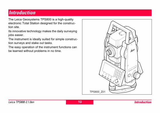
IntroductionThe Leica Geosystems TPS800 is a high-quality electronic Total Station designed for the construc-tion site.Its innovative technology makes the daily surveying jobs easier.The instrument is ideally suited for simple construc-tion surveys and stake out tasks.The easy operation of the instrument functions can be learned without problems in no time.
TPS800_Z01
F2
F1
F3
F4
PAGE
MENU
FNC
USER
78
945
612
30.
ABCDEF
GHIJKLMNO
PQRSTUVWX
/$%_@&
* ?!
YZ
ESC
10 IntroductionLeica TPS800-2.1.0en
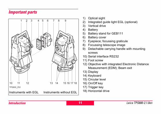
Important parts1) Optical sight2) Integrated guide light EGL (optional)3) Vertical drive4) Battery5) Battery stand for GEB1116) Battery cover7) Eyepiece; focussing graticule8) Focussing telescope image9) Detachable carrying handle with mounting
screws10) Serial interface RS23211) Foot screw12) Objective with integrated Electronic Distance
Measurement (EDM); Beam exit 13) Display14) Keyboard15) Circular level16) On/Off key17) Trigger key18) Horizontal driveInstruments with EGL Instruments without EGL
TPS800_Z02
F2
F1
F3
F4
PAGE
MENU
FNC
USER
78
945
612
30.
ABCDEF
GHIJKLMNO
PQRSTUVWX
/$%_@&
* ?!
YZ
ESC
11Introduction Leica TPS800-2.1.0en

Technical terms and abbreviationsZA = Line of sight / collimation axisTelescope axis = line from the reticle to the centre of the objective.SA = Standing axisVertical rotation axis of the telescope.KA = Tilting axisHorizontal rotation axis of the telescope (Trunion axis).V = Vertical angle / zenith angleVK = Vertical circleWith coded circular division for reading the V-angle.Hz = Horizontal directionHK = Horizontal circleWith coded circular division for reading the Hz-angle.
TPS800_Z03
12 IntroductionLeica TPS800-2.1.0en

Standing axis inclinationAngle between plumb line and standing axis. Standing axis tilt is not an instrument error and is not eliminated by measuring in both faces. Any possible influence it may have on the Hz-direction resp. V-angle is elliminated by the dual axis compensator.Line-of-sight error (Hz-collima-tion)The line-of-sight error is the devia-tion from the perpendicular between tilting axis and line-of-sight. This could be eleminated by measuring in both faces.V-Index (Vertical index error)With horizontal line-of-sight the V-circle reading should be exactly 90°(100gon). The deviation from this values is termed V-index (i).
Plumb line / CompensatorDirection of gravity. The compen-sator defines the plumb line within the instrument.
ZenithPoint on the plumb line above the observer.
ReticleGlass plate within the telescope with reticle.
TPS800_Z04
TPS800_Z05
TPS800_Z06
TPS800_Z07
TPS800_Z08
TPS800_Z09
13Introduction Leica TPS800-2.1.0en
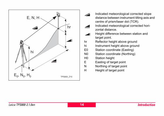
Indicated meteorological corrected slope distance between instrument tilting axis and centre of prism/laser dot (TCR).Indicated meteorological corrected hori-zontal distance.Height difference between station and target point.
hr Reflector height above groundhi Instrument height above groundE0 Station coordinate (Easting)N0 Station coordinate (Northing)H0 Station heightE Easting of target pointN Northing of target pointH Height of target point
TPS800_Z10
14 IntroductionLeica TPS800-2.1.0en

Area of applicabilityThis User Manual is valid for all instruments of the TPS800 Series.
PC Program Package Leica Geo Office Tools (LGO-Tools)The program package LGO-Tools is used for the data exchange between the Total Station and the PC. It contains several auxiliary programs in order to support your use of the Instrument.
Installation on the PCThe installation program can be found on the CD-ROM supplied. Please note that LGO-Tools can only be installed on computers with MS Windows 98, 2000 or XP operating systems.
Any previous versions of LGO-Tools on your computer must be uninstalled first before installing the new version.For the installation call program "setup.exe" in the directory \LGO-Tools on the CD-ROM and follow the input instructions of the installation program.
Program contentAfter successful installation the following programs appear:
15Introduction Leica TPS800-2.1.0en

Tools• Data Exchange Manager
For data exchange of coordinates, measure-ments, codelists and output formats between instrument and PC.
• Coordinate EditorImport/Export as well as creating and processing of coordinate files.
• Codelist Manager For creating and processing of codelists.
• Software Upload For loading system software and EDM-software.
For EDM Software upload only LGO/LGO-Tools Software Version 3.0 or higher must be used for error free operation.Not using the correct upload Software can permanently damage the instrument.
Before the Software Upload, always insert a charged battery into the instrument.
• Format Manager For creating of own, special formatted data output files.
• Configuration Manager Import/Export as well as creating of instrument configuration.
For more informationen about LGO-Tools refer to the comprehensive Online Help.
16 IntroductionLeica TPS800-2.1.0en

Power SupplyUse the Leica Geosystems batteries, chargers and accessories or accessories recommended by Leica Geosystems to ensure the correct functionality of the instrument.Power for the instrument can be supplied either internally or externally. An external battery is connected to the instrument using a LEMO cable.• Internal battery:
One GEB111 or 121 battery fit in the battery compartment.
• External battery:One GEB171 battery connected via cable.
1 GEB1212 GEB1113 Single cells in the battery adapter GAD39
Your Leica Geosystems instrument is powered by rechargeable plug-in batteries. For this product, we recommend the basic battery (GEB111) or the Pro battery (GEB121). Optionally six single cells can be used with the GAD39 battery adapter. Six single cell batteries (1.5 V each) supply 9 Volts. The voltmeter on the instrument is designed for a voltage of 6 Volts (GEB111/ GEB121).
The battery charge is not displayed correctly when using single cells. Use the single cells with the battery adapter as emergency power supply. The advantage of the single cells is in a lower rate of discharge even over long periods.
TPS800_Z63
1 2 3
17Introduction Leica TPS800-2.1.0en

Operating the InstrumentThe on / off key is located on the side cover of the Total Station.
All shown displays are examples. It is possible that local software versions are different to the basic version.
Keypad
1) FocusActively measured field.
2) Symbols3) Fixed keys
Keys with firmly assigned functions.4) Alphanumeric keys5) Navigation keys
Control of input bar in edit and input mode or control of focus bar.
6) Function keysAre assigned the variable functions displayed at the bottom of the screen.
7) Softkey barDisplays functions that can be called up with the function keys.
TPS800_Z11
6
7
18 Operating the InstrumentLeica TPS800-2.1.0en

Fixed keys[PAGE] Scrolls to next page when a dialogue-
consists of several pages.[MENU] Accesses programs, settings, the data
manager, adjustments, communica-tions parameters,system information and data transfer.
[USER] Key, programmable with function from the FNC menu.
[FNC] Quick-access to measurement-supporting functions.
[ESC] Quit a dialog or the edit mode with acti-vation of the "previous" value. Return to next heigher level.Confirm an input; continue to the next field.
Trigger keyThe measurement trigger has three settings (ALL,DIST, OFF).The key can be activated in the configuration menu.
At menus with multiple entries a shortcut number is shown on the right of each entry.Using this number allowing a direct start, without paging.
19Operating the Instrument Leica TPS800-2.1.0en

Distance measurementA laser distancer (EDM) is incorporated into the instruments of the TPS800 series.In all versions, the distance can be determined by using an Laser beam which emerges coaxially from the telescope objective.
Measurements to strongly reflecting targets such as to traffic lights in Reflector EDM mode without prism should be avoided. The measured distances may be wrong or inaccu-rate.For applications without reflector a special arrange-ment of the EDM, and appropriate arrangement of the beam paths, enable ranges of over five kilo-metres to be attained with standard prisms. Miniprisms, 360° reflectors and reflector tapes can also be used, and measurement is also possible without a reflector.
When a distance measurement is trig-gered, the EDM measures to the object which is in the beam path at that moment.
If e.g. people, cars, animals, swaying branches, etc. cross the laser beam while a measurement is being taken, a fraction of the laser beam is reflected and may lead to incorrect distance values.Avoid interrupting the measuring beam while taking reflectorless measurements or measurements using reflective foils. Measurements to prism reflectors are only critical if an object crosses the measuring beam at a distance of 0 to 30m and the distance to be measured is more than 300m.In practice, because the measuring time is very short, the user can always find a way of avoiding these critical situations.
Very short distances may be measured reflectorless in IR mode to well reflecting targets. Note that the distances are corrected with the addi-tive constant defined for the active reflector.
20 Operating the InstrumentLeica TPS800-2.1.0en

Incorrect result
Correct result
ReflectorlessBe sure that the laser beam is not reflected
by anything close to the line of sight (e.g. highly reflective objects).
When a distance measurement is triggered, the EDM measures to the object which is in the beam path at that moment. In case of temporary obstruction (e.g. a passing vehicle, heavy rain, fog or snow) the EDM may measure to the obstruction.
When measuring longer distances, any divergence of the red laser beam from the line of sight might lead to less accurate measurements. This is because the laser beam might not be reflected from the point at which the crosshairs are pointing.Therefore, it is recommended to verify that the R-laser is well collimated with the telescope line of sight (refer to the chapter "Checking and adjusting").
Do not measure with two instruments to the same target simultaneously.
TPS800_Z12
TPS800_Z13
21Operating the Instrument Leica TPS800-2.1.0en
Red laser to prismsAccurate measurements to prisms should
be made with the standard program (Reflector EDM mode).
Red laser to reflector tapeThe visible red laser beam can be used to measure to reflective foils, also. To guarantee the accuracy the red laser beam must be perpendicular to the reflector tape and it must be well adjusted (refer to the chapter "Checking and adjusting").
Make sure the additive constant belongs to the selected target (reflector).
22 Operating the InstrumentLeica TPS800-2.1.0en

Softkeys
Under softkeys, a selection of commands and functions is listed at the bottom of the screen. They can be activated with the corresponding function keys. The available scope of each function depends on the applications / functions currently active.
General softkeys:[ALL] Starts distance and angle measure-
ments and saves measured values.[DIST] Starts distance and angle measure-
ments without saving measured values.[REC] Saves displayed values.[ENTER] Deletes current value in the display and
is ready for the input of a new value.[ENH] Opens the coordinate input mode.[LIST] Displays the list of available points.[FIND] Starts the search for the point entered.[EDM] Displays EDM settings.[IR/RL] Toggles between reflector- and reflec-
torless measurement modes.[PREV] Back to last active dialog.[NEXT] Continue to next dialog.
Returns to highest softkey level.To next softkey level.
[OK] Set displayed message or dialog and quit dialog.
Find further information about menu/appli-cationspecific buttons in the relevant sections.
IR
I DIST ALL
PtID : 982Hz : 50.0000 gV : 66.6667 g : 67.903 m : 3.987 m
DIST
MEASURE 3/4
23Operating the Instrument Leica TPS800-2.1.0en

SymbolsDepending on software version different symbols are displayed indicating a particular operating status.
A double arrow indicates choice fields.
Using the navigation keys the desired parameter can be selected. Quits a selection with the enter key or the navigation keys.
Indicates that several pages are avail-able which can be selected with [PAGE].
Indicates telescope position I or II.
Indicates that Hz is set to "left side angle measurement" (anti-clockwise).
Status symbol "EDM type"Reflector EDM mode for measuring to prisms and reflective targets.Reflectorless EDM (visible) for measuring to all targets.
Status symbol "Battery capacity"The battery symbol indicates the level of the remaining battery capacity (75% full shown in the example).
Status symbol "Compensator"Compensator is on.
Compensator is off.
Status symbol "Offset"! Offset is active.
Status symbol "Character Input"Numeric Mode
Alphanumeric Mode
IR
RL
012
ABC
24 Operating the InstrumentLeica TPS800-2.1.0en

Menu tree[MENU] > Confirm menu selection.[PAGE] Scroll to next page.
Depending on user interface sequence and arrangement of menu items may be different.
-
—— Programs —— Surveying —— Stake Out —— Free Station —— COGO —— Tie Distance —— Area —— Remote Height —— Reference Line/Arc —— 2D Road —— Construction —— Settings —— Contrast, Trigger Key, USER Key, V-Setting, Tilt Correction, Hz Collimation —— Sector Beep, Beep, Hz Incrementation, Reticle Illumin., DSP Heater, Auto-Off —— Min. Reading, Angle Unit, Distance Unit, Temperature Unit, Pressure Unit, Code Record —— Face I Definition, Data Output, GSI 8/16, Mask 1/2, —— EDM Settings —— EDM-Mode —— Prism Type —— Prism Constant —— Laser-Point —— Guide Light
Menu, Page 1
—— File Management —— Job —— Fixpoints —— Measurements —— Codes —— Initialize Memory —— Memory Statistic
—— Adjustments —— Hz-Collimation —— V-Index —— View Adjustment Data —— Communication Parameters —— Baudrate —— Databits —— Parity —— Endmark —— Stopbits —— Data Transfer —— Job —— Data —— Format —— Auto Start (Start-up sequence) —— System Info —— Battery —— Instrument Temperature —— Display Heater —— Date —— Time —— SW-Info Operating-System, Application SW, Layout, Instrument Type, Serial Number —— PIN Protection
Menu, Page 1
Menu, Page 2
25Operating the Instrument Leica TPS800-2.1.0en

Measuring Preparation / Setting up
UnpackingRemove instrument from transport case and check for completeness:
1) Data cable (optional)2) Zenith eyepiece or eyepiece for steep angles
(optional)3) Counterweight for eyepiece for steep angles
(optional)4) Removable tribrach (optional)5) Battery charger and accessories (optional)6) Two Allen keys each, Adjusting pins7) Battery GEB111 (optional)8) Sun filter (optional)9) Battery GEB121 (optional)10) Mains adapter for battery charger (optional)11) Spacing bracket GHT 196 for instrument height
meter (optional)12) Instrument height meter GHM 007 (optional)13) Mini prism rod (optional)14) Total Station15) Mini prism + holder (optional)16) Mini target plate (only for TCR instruments)17) User Manual18) Protective cover / Lens hood19) Tip for mini prism (optional)
TPS800_Z1410
9
8
7
6
54321
19
18
1716
15
14
13
12
11
26 Measuring Preparation / Setting Leica TPS800-2.1.0en

BatteriesInserting / Replacing Battery
1. Remove battery holder.2. Remove battery.
3. Insert battery into battery holder.4. Insert battery holder into instrument.
Insert battery correctly (note pole markings on the inside of the battery holder). Check and insert battery holder true to side into the housing. • To charge the battery refer to chapter "Charging
the batteries".• For the type of battery refer to chapter "Tech-
nical data".
TPS800_Z15 1. 2. 3. 4.TPS800_Z16
27Measuring Preparation / Setting Leica TPS800-2.1.0en

When using the GEB121 battery, remove the spacer for the GEB111 from the battery compartment.
Primary use/charging• The batteries must be charged prior to using for
the first time because it is delivered with an energy content as low as possible.
• For new batteries or batteries that have been stored for a long time (> three months), it is effectual to make 2 - 5 charge/discharge cycles.
• The permissible temperature range for charging is between 0°C to +35°C / +32°F to +95°F. For optimal charging we recommend a low ambient temperature of +10°C to +20°C / +50°F to +68°F.
Operation/DischargingThe batteries can be operated from -20°C to
+55°C/-4°F to +131°F.Low operating temperatures reduce the capacity that can be drawn; very high operating temperatures reduce the service life of the battery.
28 Measuring Preparation / Setting Leica TPS800-2.1.0en

Setting up the tripod 1. Loosen the clamping screws on the tripod legs, pull out to the required length and tighten the clamps.
2. In order to guarantee a firm foothold sufficiently press the tripod legs into the ground. When pressing the legs into the ground note that the force must be applied along the legs.
When setting up the tripod pay attention to a horizontal position of the tripod plate. Slight corrections of inclination can be made with the foot screws of the tribrach. Larger corrections must be done with the tripod legs.
When using a tribrach with an optical plummet, the laser plummet cannot be used.
TPS800_Z19
TPS800_Z20
29Measuring Preparation / Setting Leica TPS800-2.1.0en

Careful handling of tripod• Check all screws and bolts for correct fit.• During transport always use the cover supplied.• Use the tripod only for surveying tasks.
TPS800_Z21
30 Measuring Preparation / Setting Leica TPS800-2.1.0en

Instrument SetupDescriptionThis topic describes an instrument setup over a marked ground point using the laser plummet. It is always possible to set up the instrument without the need for a marked ground point.
Important features:• It is always recommended to shield the
instrument from direct sunlight and avoid uneven temperatures around the instru-ment.
• The laser plummet described in this topic is built into the vertical axis of the instrument. It projects a red spot onto the ground, making it appreciably easier to centre the instrument.
• The laser plummet cannot be used in conjunction with a tribrach equipped with an optical plummet.
31Measuring Preparation / Setting Leica TPS800-2.1.0en

Setup step-by-step
1 Extend the tripod legs to allow for a comfortable working posture. Position the tripod over the marked ground point, centring it as well as possible.
2 Fasten the tribrach and instrument onto the tripod.
3 Turn on the instrument and switch on the laser plummet and electronic level by pressing [FNC] > [Level/Plummet].
4 Move the tripod legs (1) and use the tribrach footscrews (6) to centre the plummet (4) over the ground point.
5 Adjust the tripod legs to level the circular level (7).6 By using the electronic level turn the tribrach
footscrews (6) to precisely level the instrument.Refer to "Levelling up with the electronic
level step-by-step" for more information.7 Centre the instrument precisely over the ground
point (4) by shifting the tribrach on the tripod plate (2).
8 Repeat steps 6. and 7. until the required accu-racy is achieved.
2
6
7
5 4
5
5 1
3
1
1
TPS800_Z102
32 Measuring Preparation / Setting Leica TPS800-2.1.0en
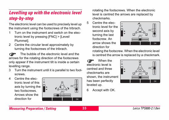
Levelling up with the electronic level step-by-stepThe electronic level can be used to precisely level up the instrument using the footscrews of the tribrach.1 Turn on the instrument and switch on the elec-
tronic level by pressing [FNC] > [Level/Plummet].
2 Centre the circular level approximately by turning the footscrews of the tribrach.
The bubble of the electronic level and the arrows for the rotating direction of the footscrews only appear if the instrument tilt is inside a certain levelling range.3 Turn the instrument until it is parallel to two foot-
screws.4 Centre the elec-
tronic level of this axis by turning the two footscrews. Arrows show the direction for
rotating the footscrews. When the electronic level is centred the arrows are replaced by checkmarks.
5 Centre the elec-tronic level for the second axis by turning the last footscrew. An arrow shows the direction for rotating the footscrew. When the electronic level is centred the arrow is replaced by a checkmark.
When the electronic level is centred and three checkmarks are shown, the instrument has been perfectly leveled up. 6 Accept with OK.
33Measuring Preparation / Setting Leica TPS800-2.1.0en

Laser intensityChanging the laser intensityExternal influences and the surface conditions may require the adjustment of the intensity of the laser. The laser can be adjusted in 25% steps as required.
Hints for positioning
Positioning over pipes or depressionsUnder some circumstances the laser dot is not visible (e.g. over pipes). In this case, the laser dot can be made visible by using a transparent plate so the the laser dot can be easily aligned to the centre of the pipe.
TPS800_Z24 TPS800_Z25
34 Measuring Preparation / Setting Leica TPS800-2.1.0en

Input modeDue to the alphanumerical keypad you can enter characters directly.• Numeric fields:
Can only contain numerical values.By pressing a button of the numeric keypad the number will be dsiplayed.
• Alphanumeric fields:Can contain numbers and letters.By pressing a button of the alphanumeric keypad the input opens. By pressing several times you can toggle through the characters. For example: 1->S->T->U->1->S....
Edit characters1. Place cursor on character to be
edited.2. Input the new character.
3. Confirm input.
Erasing characters1. Place cursor on character to be
deleted.2. Pressing the navigation key deletes
the relevant character.3. Confirm input.
[ESC] Deletes the change and restores the previous value.
Inserting charactersIf a character was skipped (e.g. -15 instead of -125) you can insert it later.
1. Place cursor on "1".
2. Inserts an empty character on the right of "1".
3. Input the new characters.
4. Confirm input.
35Measuring Preparation / Setting Leica TPS800-2.1.0en

Character setEntry mode contains the following characters for numeric and alphanumeric input.
The character entry "*" can be used in data fields where point numbers or codes can be searched for.Signs+/- In the alphanumeric character set "+" and "-" are
treated as normal alphanumeric characters with no mathematical function.
Additional characters* Place holder during Wildcard point search (see
chapter "Wildcard search"). "+" / "-" appears only in the front position of
an input.In the edit mode the position of the decimal
place cannot be changed. The decimal place is skipped.
Numerical Alphanumerical" + " " - "" . "" 0 - 9 "
(ASCII 43) (ASCII 45) (ASCII 46) (ASCII 48 - 57)
" "" ! "" # "" $ "" % "" & "" ( "" ) "" * "" + "" , "" - "" . "" / " " : "" < "" = "" > "" ? "" @ "" A - Z"" _ "
" ‘ "
(ASCII 32) [space] (ASCII 33) (ASCII 35) (ASCII 36) (ASCII 37) (ASCII 38)(ASCII 40)(ASCII 41) (ASCII 42) (ASCII 43) (ASCII 44) (ASCII 45) (ASCII 46) (ASCII 47)(ASCII 58)(ASCII 60)(ASCII 61)(ASCII 62) (ASCII 63) (ASCII 64) (ASCII 65 .. 90)(ASCII 95) [Underscore](ASCII 96)
36 Measuring Preparation / Setting Leica TPS800-2.1.0en

PointsearchPointsearch is a global function used by applications to e.g. find internally saved measured or fixed points.It is possible for the user to limit the point search to a particular job or to search the whole storage.The search procedure always finds fixed points before measured points that fulfill the same search criteria. If several points meet the search criteria, then the points are listed according to their age. The instrument finds the most current (youngest ) fixed point first.Direct searchBy entering an actual point number (e.g. "P13") all points with the corresponding point number are found.
[VIEW] Displays the coordinates of the selected point.
[ENH] For manual input of coordinates.[OK] Confirm selected point.[JOB] To select a different job.
Job : ALL JOBSPtID : P13
POINT SEARCH
VIEW JOB OK
P13 FIXPTP13 MEASP13 MEAS
37Measuring Preparation / Setting Leica TPS800-2.1.0en

Wildcard searchThe Wildcard search is indicated by a "*". The aste-risk is a place holder for any following sequence of characters.Wildcards are always used if the point number is not fully known, or if a batch of points is to be searched for.
Starts point search.Examples:* All points of any length are found.A All points with exactly the point number "A" are
found.A* All points of any length starting with "A" are
found (e.g.: A9, A15, ABCD).
*1 All points of any length with a "1" as the second character are found (e.g.: A1, B12, A1C).
A*1 All points of any length with an "A" as the first character and a "1" as the third character are found. (e.g.: AB1, AA100, AS15).
Job : PROJ_3PtID : A*1
POINT SEARCH
38 Measuring Preparation / Setting Leica TPS800-2.1.0en

MeasuringAfter switching on and setting up correctly, the Total Station is immediately ready for measuring.In the measurement display it is possible to call up fixed keys and function keys, as well as trigger keys and their functions.
All shown displays are examples. It is possible that local software versions are different to the basic version.
Example of a possible measuring display:
Calling up the assigned function.
IR
I DIST ALL
PtID : 982Hz : 50.0000 gV : 66.6667 g : 67.903 m : 3.987 m
MEASURE 2/4
-
39Measuring Preparation / Setting Leica TPS800-2.1.0en

FNC KeyUnder [FNC] several functions can be called up. Their applications are described below.
Functions can also be started directly from the different applications.
Each function from the FNC menu can be assigned to the [USER]-key (see chapter "Settings").
Light On /OffSwitches display light on / off.
Level/PlummetThis function enables the electronic bubble and the range of intensity settings of the laser plummet.
IR/ RL ToggleChange between the two EDM types IR (on Reflec-tors) and RL (Reflectorless). New setting is displayed for about one second.
IR: Distance measurements with prisms.RL: Distance measurements without prisms.Find more information in chapter "EDM Settings".
Laser PointerSwitches on or off the visible laser beam for illumi-nating the target point. The new settings are displayed for about one second and then saved.
Free-CodingSelect code from the codelist or enter a new code.
UnitsDisplays the current distance and angle unit and gives the possibility to change these.
40 FNC KeyLeica TPS800-2.1.0en

Delete Last RecordThis function deletes the last recorded data block. This can be either a measurement block or a code block.
Deleting the last record is not reversible !Only records can be deleted which were
recorded in "Surveying" or in "Measuring".
Lock with PINThis function is used to prevent unauthorized use of the instrument. It enables you to lock the instru-ment from any application by pressing [FNC] > [Lock with PIN] without switching off the instrument. After that the instrument will prompt for a PIN code entry.The function is available when the PIN protection is activated under [MENU] > [PIN].
Check TieCalculation and display of the slope and horizontal distance, height difference, azimuth, grade, and co-ordinate differences between the last two measured
points. Valid distance measurements are required for the calculation.
Important MessagesLess than two valid measurements!MeaningThe values cannot be calculated as there exist less than 2 valid measurements.
TPS800_Z79
AziN
41FNC Key Leica TPS800-2.1.0en

TrackingSwitches on or off the tracking measurement mode. The new setting is displayed for approx. one second and then set. The function can only be activated from within the same EDM type and prism type.
The following options are available:
The last active measurement mode remains set when the instrument is switched off.
Target OffsetIf it is not possible to set up the reflector directly, or it is not possible to aim the target point directly, the offset values (length, cross and/or height offset) can be entered. The values for the angle and distances are calculated directly for the target point.
MP: Measurement pointOP: Offset point
EDM Type Tracking measurement modeOff <=> On
IR IR-Fine <=> IR_Track / IR-Fast <=> IR-TrackRL RL-Short <=> RL-Track
MP
OP
TPS800_Z26
L_Off -
L_Off+T_Off -
T_Off+
42 FNC KeyLeica TPS800-2.1.0en

T_Off: Length offsetL_Off: Cross offsetH_Offset +: Offset point is higher than measurement
Procedure:1. Enter the offset values (length, cross and/or
height) as per the sketch.2. Define the period for which the offset is to apply.3. [RESET]: Sets eccentricity to zero.4. [SET]: calculates the corrected values and
jumps to the application from which the offset function was started. The corrected angle and
distances are displayed as soon as a valid distance measurement has been triggered or exists.
The period of applicability can be set as follows:
The offset values are always reset to 0 when the application is quit.
Main SettingsEnables you to change the most important settings.
INPUT RESET SET
T_Offset: 0.600 mL_Offset: 0.800 mH_Offset: 0.500 mMode : PERMANENT
TARGET OFFSETReset after REC The offset values are reset to 0
after the point is saved.
Permanent The offset values are applied to all further measurements.
43FNC Key Leica TPS800-2.1.0en

Height TransferExample:
1) Reflector 12) Reflector 23) Reflector 34) Instrument
This function determines the height of the instru-ment from measurements to a maximum of 5 target points, with known heights, in two faces.With measurements to several targets, the improve-ment is indicated in the "delta" value.Procedure:1. Select known point and input reflector height.2. After triggering the measurement with [ALL], the
calculated height H0 is displayed.[AddPt] Add another height of a known
point.[FACE] Measure to the same target in
second face.3. [SET] Save the changes and set the
station.
TPS800_Z27
44 FNC KeyLeica TPS800-2.1.0en

Hidden PointExample:
1 E, N, H of Hidden Point2 Rod Length3 Distance R1-R2
The program allows measurements to a point that is not directly visible, using a special hidden-point rod.
Procedure:1. Measure to first prism (P1).
[All] Starts measurement and proceeds to step 2.
[ROD] Allows you to define the rod and the EDM-Settings.
Rod LengthTotal length of hidden-point rod.Dist. R1-R2Spacing between the centers of reflector R1 and prism R2.Meas. TolLimit for the difference between the given and measured spacing of the reflectors. If the tolerance value is exceeded, the program will issue a warning.EDM-ModeChanges the EDM-Mode.Prism typeChanges the prism type.Prism ConstDisplays the prism constant.
1
2
3
45FNC Key Leica TPS800-2.1.0en

2. [All] Starts measurement and proceeds to the Result dialog.
3. Result is displayed.
[NEW] Returns to step 1.[FINISH] Returns to calling application.
FINISH NEW
PtID : 12
Desc. : GR
East : 110.871 m
North : 99.991 m
Heigth : 102.884 m
HIDDEN POINT RESULT
46 FNC KeyLeica TPS800-2.1.0en

Programs
Application pre-settingsThese are programs that precede the application programs and are used to set up and organize data collection. They are displayed after selecting an application. The user can select the start programs individually.
[• ] Settings made.[ ] Settings not made.
Find further information about individual start-up programs on the subsequent pages !
Setting jobAll data is saved in JOBS, like directories. Jobs contain measurement data of different types (e.g. measurements, codes, fixed points, stations,...) and are individually manageable and can be readout, edited or deleted separately.[NEW] Creating a new job.[SET] Setting the job and back to start-up
programs.All subsequent recorded data is stored in
this job/directory.If no job was defined and an application was
started or if in "Meas & Rec" [ALL] or [REC] was trig-gered, then the system automatically creates a new job and names it "DEFAULT". F1 F2 F3 F4
[ ] F1 Set Job
[ ] F2 Set Station
[ ] F3 Set Orientation
F4 Start
SETTING OUT
47Programs Leica TPS800-2.1.0en

Setting StationEach coordinate computation relates to the currently set station.At least plan coordinates (E, N) are required for the station. The station height can be entered if required. The coordinates can be entered either manually or read from the internal memory.
Known Point1. Select a PtID stored in internal memory.2. Input instrument height.
[OK] Sets the station.
Set manually1. [ENH] Calls up manual point input
dialogue.2. Input PtID and coordinates.3. [SAVE] Saves station coordinates.
Continues to the input of the instru-ment height.
4. [OK] Sets the station.If no station was set and no application
started and if in "Meas & Rec " [ALL] or [REC] was activated, then the last station is set as the current station.
TPS800_Z28
48 ProgramsLeica TPS800-2.1.0en

OrientationWith the orientation, Hz-direction can be input manually or points with known coordinates can be set.
Method 1: Manual input 1. To input a random Hz-orientation.
2. Input of Hz-direction, reflector height and PtID.3. [ALL] Triggers measurement and sets
orientation.[REC] Records Hz-direction and sets
orientation.
Method 2: with coordinatesTo determine the orientation, a target with known coordinates can also be used.1. As orientation with coordinates.2. Input of the orientation point number and to
determine the point found.3. To input and confirm the reflector height.For determining the orientation a maximum of 5 target points with known coordinates can be used.
1) 1. Target point2) 2. Target point3) 3. Target point
TPS800_Z29
49Programs Leica TPS800-2.1.0en

Orientation coordinates can be either obtained from the internal memory or entered manually.
After each measurement you are asked wether to proceed or not. Answering with yes brings you back to the Measurement dialog, to take an additional measurement. Answering with no brings you to the Result dialog1/I Status indication; shows that first point was
measured in telescope position I.1/I II First point measured in telescope pos. I and
II.
Hz: After the first measurement the finding of other target points (or the same point when changing the telescope position) is easier by setting the indicated angle difference near to 0°00'00" by turning the instrument.
: Difference between horizontal distance to target point computed from coordinates and the measured distance.
Display of computed orientation
[OK] Set computed Hz-orientation.
IR
I ALL DIST REC EDM
PtID : 201 hr : 1.300 mBsBrg: 236°56'14" Hz : 51°12'23" : 0.569 m
SIGHT TARGET POINT 3/I II
I
PREV RESID OK
NoPts. : 2 Station : 200HzCor : 123°00'23"StDev : ± 0°00'08"
ORIENTATION RESULT
50 ProgramsLeica TPS800-2.1.0en

If more than one target point is measured then the orientation is computed using the "least squares method".
Displaying residuals[RESID] Display of residuals.
1) Actual2) Design
H: Height correction: correction of the horizontal distance
Hz: Correction of Hz-angle.
RESIDUALS 1/3
PREV
BsPt : ABC1 Hz : -0°00'23" : -0.045 m H : 0.075 mHzCor: 123°00'23"
TPS800_Z30
51Programs Leica TPS800-2.1.0en

Useful information• If the orientation is only measured in telescope
position II the Hz-orientation is based on tele-sope position II. If measured only in telescope position I or mixed the Hz-orientation is based on telescope position I.
• The prism height may not be changed during measurements in the first and second telescope position.
• If a target point is measured several times in the same telescope position the last valid measure-ment is used for the computation.
If no orientation was set and an application was started resp. if in "Meas & Rec" [ALL] or [REC] was triggered, then the current Hz-direction and V-angle are set as orientation.
52 ProgramsLeica TPS800-2.1.0en

ApplicationsIntroductionApplications are predefined programs, that cover a wide spectrum of surveying duties and facilitate daily work in the field.The following applications are available:• Surveying• Stake Out• Tie Distance• Area & Volume• Free Station• Reference Line/Arc• Remote Height• Construction• Cogo (optional)• 2D-Road (optional)
[MENU] 1. Press the [MENU] fixed key.
2. Selecting the "Program" option.
3. Calling up applications and acti-vating start programs.[PAGE] Scroll to next page.
-
53Programs Leica TPS800-2.1.0en

SurveyingWith the program Surveying the measurement of an unlimited number of points is supported. It is compa-rable to "Meas & Rec", but includes stationing, orien-tation and coding.
Procedure:1. Input PtID, codes and the reflector height if
desired.2. [ALL] Triggers and records measure-
ments.[IndivPt] Switches between individual and
current point number.
Three coding methods are available:1. Simple coding:
Input a code into the relevant box. The code is stored along with the corresponding measure-ment.
2. Expanded coding: Press the [CODE] softkey. The code that was input is searched for within the code list and it is possible to add attributes to the code.
3. Quick coding:Press the [Q-Code] softkey and enter the shortcut to the code. The code is selected and the measurement starts.
TPS800_Z31
54 ProgramsLeica TPS800-2.1.0en

Stake outThis program calculates the required elements to stakeout points from coordinates or manualy entered angles, horizontal distances and heights. Stake out differences can be displayed conti-nuously.Stake out coordinates from memoryProcedure:
Select the point.[DIST] Starts measurement and calculation of
the stake-out elements.[REC] Saves the displayed values.[B&D] Input direction and Hz-distance of stake
out point.[MANUAL] Enables simplified input of a point
without PtID and without the possibility of storing the data of the point.
Polar Stake outNormal indication of polar stake out offsets.
1) Actual2) Point to be stake out
Hz: Angle offset: positive if point to be set-out is to the right of the actual direction.
: Longitudinal offset: positive if point to be stake out is further away.
: Height offset: positive if point to be stake out is higher than measured point.
TPS800_Z32
55Programs Leica TPS800-2.1.0en

Orthogonal Stake outThe position offset between measured point and stake out point is indicated in a longitudinal and transversal element.
1) Actual2) Point to be stake out
L: Longitudinal offset: positive if nominal point further away.
T: Transversal offset, perpendicular to line-of-sight: positive if nominal point is to the right of measured point.
Cartesian Stake outStake out is based on a coordinate system and the offset is divided into a north and east element.
1) Actual2) Point to be stake out
E Easting offset between stake out and actual point.
N Northing offset between stake out and actual point.
TPS800_Z33
TPS800_Z34
56 ProgramsLeica TPS800-2.1.0en
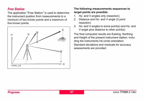
Free Station The application "Free Station" is used to determine the instrument position from measurements to a minimum of two known points and a maximum of five known points.
The following measurements sequences to target points are possible:1. Hz- and V-angles only (resection)2. Distance and Hz- and V-angle (3 point
resection)3. Hz- and V-angles to some point(s) and Hz- and
V-angle plus distance to other point(s).The final computed results are Easting, Northing and Height of the present instrument station, inclu-ding the instruments Hz-circle orientation. Standard deviations and residuals for accuracy assessments are provided.
TPS800_Z35
57Programs Leica TPS800-2.1.0en
Measuring facilitiesSingle face I or II or dual face I + II measurements are always possible. No specific point sequence or specific face sequences are required.Gross errors checks are made for dual face measu-rements to ensure the same point(s) are sighted with the other face.
If a target point is measured several times in the same telescope position the last valid measure-ment is used for computation.Measurement restrictions:• 2 face measurements
When measuring the same target in both faces, the reflector height may not be altered when changing the telescope position.
• Target points with 0.000 heightTarget points with 0.000 height are discarded for height processing. If target points have a valid height of 0.000 m, use 0.001 m to enable it for height processing.
Computation procedureThe measuring procedure automatically determines the mothod of evaluation, e.g. resection, 3 point resection, etc.If more than the minimum required measurements are performed, the processing routine uses a least squares adjustment to determine the plan position and averages orientation and heights.1. The original averaged face I and face II
measurements enter the computation process. 2. All measurements are treated with the same
accuracy, whether these are measured in single or dual face.
3. Easting and northing is determined by the method of least squares, including standard deviation and improvements for Hz-direction and horizontal distances.
4. The final height (H) is computed from averaged height differences based on the original measurements.
5. The Hz-circle orientation is computed with the original averaged face I and face II measure-ments and the final computed plan position.
58 ProgramsLeica TPS800-2.1.0en

Procedure:
Enables you to define an accuracy limit.
Here you can enter a limit for the standard deviation values. If your computed deviation exceeds the limit a warning dialog appears, where you can decide wether to proceed or not.1. Input of the name of the station and the height of
the instrument.2. Input of the target PtID and the reflector height.
[ALL] Triggers angle and distance measurement (3 point resection).
[REC] Saves Hz-direction and V-angle (resection).
[ ] F1 Set Job
F2 Set accuracy limit
F4 Start
FREE STATION
ACCURACY SETTINGEnter accuracy limit!
OK
Status : onSt.dev.East : 0.005 mSt.dev.North : 0.005 mSt.dev.Height: 0.010 mSt.dev.Angle : 0.0020 g
IR
I ALL AddPt COMPUTE
PtID : 982 hr : 1.500 mHz : 68.4132 gV : 98.4760 g : 123.760 m
FREE STATION 3/I II
I
59Programs Leica TPS800-2.1.0en

[AddPt] Input another backsight point.[COMPUTE] Calculates and displays the station
coordinates, if at least 2 points and a distance were measured.
3/I Indicates that the third point in tele-scope position I was measured.
3/I II Indicates that the third point in tele-scope positions I and II.
ResultsDisplays calculated station coordinates:
[AddPt] Switches to measurement display, to measure additional points.
[RESID] Displays residuals.[STDEV] Displays standard deviation.[SET] Sets the displayed coordinates and
instrument height as new station.
AddPt RESID StdDev SET
Station : Stp1 hi : 1.560 mE0 : 102.338 mN0 : 406.426 mH0 : 99.350 m
FREE STATION RESULT
60 ProgramsLeica TPS800-2.1.0en

If the instrument height was set to 0.000 in the setup screen, then the station height refers to height of trunnion axis.Displays standard deviations:
S.Dev E0, N0, H0 Standard deviation of the station coordinates
S.Dev Ang Standard deviation of the orien-tation
This dialog shows the computed residuals:Residual = Calculated value - Measured value
With the function keys, scroll between the residuals of the indi-vidual backsight points.
BACK
POINTS: 3 S.Dev E0: 0.028 mS.Dev N0: 0.012 mS.Dev H0: 0.030 mS.Dev Ang: 0.0020 g
FREE STATION STD. DEVIATIONS
FREE STATION RESIDUALS 1/3
BACK
PtID : Target 1 Hz : 0.0020 g : 0.030 m H : 0.028 m
61Programs Leica TPS800-2.1.0en

Warnings / Messages
Important messages Meaning
Selected point has no valid data ! This message occurs if the selected target point has no easting or northing coordinate.
Max 5 points supported ! If 5 points have already been measured and another point is selected. The system supports a maximum of 5 points.
Invalid data - no position computed ! The measurements may not allow final station coordinates (Eastings, North-ings) to be computed.
Invalid data - no height computed ! Either the target height are invalid or insufficient measurements are available to compute a final station height.
Insufficient space in job ! The present selected job is full and does not allow further storage.
Hz (I - II) > 0.9 deg, measure point again ! This error occurs if a point was measured in one face and the measurement in the other face differs by more than 180° ±0.9° for the horizontal angle.
V (I - II) > 0.9 deg, measure point again ! This error occurs if a point was measured in one face and the measurement in the other face differs by more than 360° - V ±0.9° for the vertical angle.
More points or distance required ! There is insufficient data measured to be able to compute a position. Either there are not enough points used or not enough distances measured.
62 ProgramsLeica TPS800-2.1.0en

Reference Line/ArcThis program facilitates the easy stake out or checking of lines for buildings, sections of road, simple excavations, etc.
Reference LineA reference line can be defined by referencing a known base line. The reference line can be offset either longitudinally, in parallel or vertically to the base line, or be rotated around the first base point as required. Furthermore the reference height can be selected as first point, second point or interpolated along the reference line.
Procedure:
1. Definition of the Base line:The base line is fixed by two base points that can be defined in three ways:• Measured points• Enter coordinates using keypad• Select point from memory.
a) Measuring base points:Input PtID and measure base points with [ALL] or [DIST] / [REC].
b) Base points with coordinates:[FIND] Starts to search for the PtID
entered.[ENH] Manually input coordinates.[LIST] Displays the list of available points.
Analogue procedure for the second base point.
1) 1st base point2) 2nd base point
TPS800_Z36
63Programs Leica TPS800-2.1.0en

3) Base line4) Reference line
2. Shifting/Rotating the Base lineThe base line can be offset longitudinally, parallel and vertically or rotated. This new line is called the reference line. All measured data refers to the refer-ence line.
BP: Base pointBL: Base line
RP: Reference pointRL: Reference lineOff: Parallel offsetL: Longitudinal offsetR: Rotation parameterInput of the parameters:
Use the navigation keys to select the shifting and rotation parameters of the refer-ence line.
BP1
BP2
BL
RP
RL
R+
L+
Off+TPS800_Z37
64 ProgramsLeica TPS800-2.1.0en

The following entries are possible:Offset+: Parallel offset of the reference line
to the right, referred to the direction of the base line (BP1-BP2).
Line+: Longitudinal offset of the start point (=reference point) of the reference line in the direction of base point BP2.
Rotate+: Rotation of the reference line clock-wise around the reference point.
Height+: Height offset; the reference line is higher than the selected reference height.
Ref.Hgt:Point 1 Height differences are computed
relative to the height of the first refer-ence point.
Point 2 Height differences are computed relative to the height of the second reference point.
Interpolated Height differences are computed along the reference line.
No Height Height differences are not computed and shown.
NewBL MEASURE STAKE SHIFT=0
REFERENCE LINE - MAIN 1/2 Length : 14.872 mEnter values to shift line:Offset : 1.000 mLine : 0.500 mHeight : 0.900 mRotate : 25.0000 g
NewBL MEASURE STAKE SHIFT=0
REFERENCE LINE - MAIN 2/2
Point 1 : 01Point 2 : 02Length : 14.872 mSelect Height Reference !Ref.Hgt : Interpolated
65Programs Leica TPS800-2.1.0en

3. Decide to measure or to stake out[MEASURE] Starts the subapplication to
measure Line & Offset (see issue 4).
[STAKE] Starts the subapplication to stake out (see issue 5).
4. "Line & Offset" subapplicationThe "Line & Offset" subapplication calculates from measurements or coordinates longitudinal, parallel offsets and height differences of the target point relative to the reference line.
1RP: 1st reference pointMP: Measured pointRL: Reference linepL: Longitudinal offsetpOff: Parallel offsetThe [L&O] function calculates from measurements or coordinates longitudinal, cross and height diffe-rences of the target point relative to the reference line.
1RP
MPL+
Off+
TPS800_Z38
RL
66 ProgramsLeica TPS800-2.1.0en
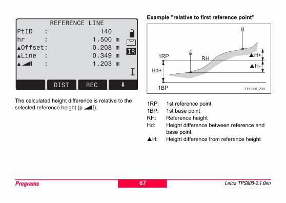
The calculated height difference is relative to the selected reference height (p ).
Example "relative to first reference point"
1RP: 1st reference point1BP: 1st base pointRH: Reference heightHd: Height difference between reference and
base pointH: Height difference from reference height
IR
I DIST REC
PtID : 140 hr : 1.500 m Offset: 0.208 m Line : 0.349 m : 1.203 m
REFERENCE LINE
H+
H-
1BP
1RP RH
Hd+
TPS800_Z39
67Programs Leica TPS800-2.1.0en
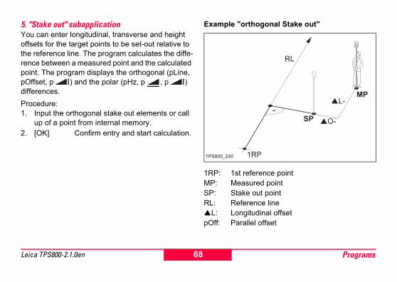
5. "Stake out" subapplicationYou can enter longitudinal, transverse and height offsets for the target points to be set-out relative to the reference line. The program calculates the diffe-rence between a measured point and the calculated point. The program displays the orthogonal (pLine, pOffset, p ) and the polar (pHz, p , p ) differences.Procedure:1. Input the orthogonal stake out elements or call
up of a point from internal memory.2. [OK] Confirm entry and start calculation.
Example "orthogonal Stake out"
1RP: 1st reference pointMP: Measured pointSP: Stake out pointRL: Reference line
L: Longitudinal offsetpOff: Parallel offset
1RP
RL
SP
MP
TPS800_Z40
L-
O-
68 ProgramsLeica TPS800-2.1.0en

Display in "Stake out" measure mode:
The signs for the distance and angle differences are correction values (required minus actual).+ Hz Turn telescope clockwise to the stake
out point.
+ The stake out point is further away than the point measured.
+ The stake out point is higher than the measured point.
IR
I DIST REC
PtID : 15 hr : 1.500 m Hz : +0.200 g : 2.368 m : 0.260 m
ORTHOGONAL STAKEOUT 1/2
IR
Offset: 2.040 m Line : 1.203 m : 0.260 m
69Programs Leica TPS800-2.1.0en

Reference ArcThis application allows the user to define a Refe-rence Arc and then measure or stake out with respect to the arc.
SP: Start point of arcEP: End point of arcCP: Centre point of circleP: Point to stakeR: Radius of circleL: Distance from start of arc, following curveOff: Perpendicular distance from arc
All arcs are defined in clockwise direction.All calculations are made in two dimensions.
Procedure:1. Define the arc
When starting the application you were asked how to define the arc. You can define the arc by:a) Center Point & Start Pointb) Start Point, End Point, RadiusDepending from type you have chosen, you have to measure/select/enter the values to proceed to step 2.
2. Decide to Measure or to Stake Out[MEASURE] Starts the subapplication to
measure Line & Offset (See issue 3).
[STAKE] Starts the subapplication to stake out (See issue 4).
3. "Line & Offset" subapplicationHere you can measure or select points from memory and you will see Line and Offset refering to the arc.
CPSP R
L+
Off - EP
P
TPS800_Z81
70 ProgramsLeica TPS800-2.1.0en
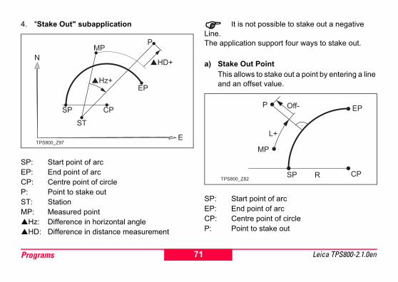
4. "Stake Out" subapplication
SP: Start point of arcEP: End point of arcCP: Centre point of circleP: Point to stake outST: StationMP: Measured point
Hz: Difference in horizontal angleHD: Difference in distance measurement
It is not possible to stake out a negative Line.The application support four ways to stake out.
a) Stake Out PointThis allows to stake out a point by entering a line and an offset value.
SP: Start point of arcEP: End point of arcCP: Centre point of circleP: Point to stake out
CPSP
MP
ST
N
E
�HD+
�Hz+
EP
P
TPS800_Z97
CPSP R
L+
Off- EPP
MP
TPS800_Z82
71Programs Leica TPS800-2.1.0en
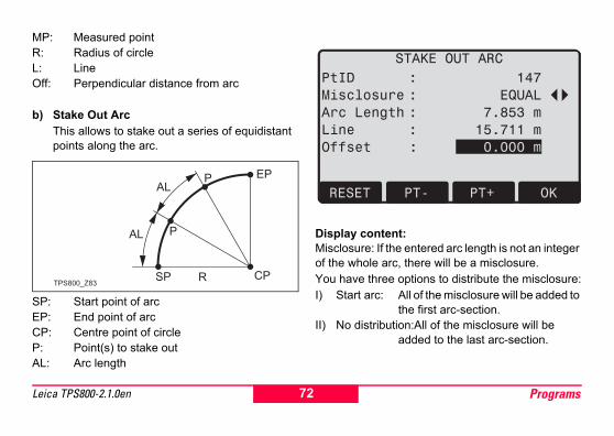
MP: Measured pointR: Radius of circleL: LineOff: Perpendicular distance from arc
b) Stake Out ArcThis allows to stake out a series of equidistant points along the arc.
SP: Start point of arcEP: End point of arcCP: Centre point of circleP: Point(s) to stake outAL: Arc length
Display content:Misclosure: If the entered arc length is not an integer of the whole arc, there will be a misclosure. You have three options to distribute the misclosure:I) Start arc: All of the misclosure will be added to
the first arc-section.II) No distribution:All of the misclosure will be
added to the last arc-section.
CPSP R
AL
AL
P
P EP
TPS800_Z83
RESET PT- PT+ OK
PtID : 147
Misclosure : EQUAL
Arc Length : 7.853 m
Line : 15.711 m
Offset : 0.000 m
STAKE OUT ARC
72 ProgramsLeica TPS800-2.1.0en

III) Equal: The misclosure will be equally distributred between all sections.
Arc Length: Enter the length of the arc-segment you want to stake out.
Line: Shows the line-value of the stake out point. This is calculated by the arc length and the selected misclo-sure distribution.
Offset: Here you can enter the offset value.[RESET] Sets the values to 0.[PT +][PT -] Toggels through the calculated
stake out points.[OK] Proceeds to Stake Out Measure
dialog.
c) Stake Out ChordThis allows to stake out a series of equidistant chords along the arc. The screen contents and the buttons shown, are the same as described in "Stake Out Arc" section.
CL: Chord length
CPSP R
CL
P
P EP
TPS800_Z84
73Programs Leica TPS800-2.1.0en

d) Stake Out AngleThis allows to stake out a series of points along the arc defined by the angle substended at the center of the angle. The screen contents and the buttons shown, are the same as described in "Stake Out Arc" section.
β: Angle
CPSP R
ββ
β
MP
EP
TPS800_Z85
74 ProgramsLeica TPS800-2.1.0en

Tie DistanceThe application Tie Distance computes slope distance, horizontal distance, height difference and azimuth of two target points measured online, selected from the Memory or entered using the Keypad. The user can choose between two different methods:
Polygonal (A-B, B-C)Radial (A-B, A-C)
Polygonal Method:
Radial Method:
CP: Centre pointIn principal both methods are the same.Any differences will be described.Procedure:1. Determine first target point.
[ALL] Starts measurement to the target point.
[FIND] Searches internal memory for point entered.TPS800_Z41
CP
1-2
1-3
1-4TPS800_Z42
75Programs Leica TPS800-2.1.0en

2. Determine second target point.Proceed as with first target point.
3. Result is displayed.Brg Azimuth between point1 and point2.
Slope distance between point1 and point2.Horizontal distance between point1 and point2.Height difference between point1 and point2.
Grade Grade [%] between point1 and point2.
Softkeys - polygonal method:[NewPt 1] An additional missing line is
computed. Program starts again (at point 1).
[NewPt 2] Point 2 is set as starting point of a new missing line. New point (Pt 2) must be measured.
[RADIAL] Switches to radial method.
Softkeys - radial method:[NewPt 1] Determine new central point.[NewPt 2] Determine new radial point.[POLY] Switch to polygonal method.
76 ProgramsLeica TPS800-2.1.0en

Area & VolumeThe application program Area is used to compute online areas of max. 50 points connected by straights. The target points have to be measured, selected from memory or entered via keyboard in clockwise direction. The calculated area is projected onto the horizontal plane (2D) or projected onto the sloped reference plane defined by 3 points (3D). Furthermore a volume with constant height can be calculated in rela-tion to the area (2D/3D)
.
a Perimeter, polygonal length from start point to the current measured point.
b Calculated area always closed to the start point P1, projected onto the horizontal plane.
P0 Station P3 Target pointP1 Start point P4 Target pointP2 Target point
P1
a
P2 P3
P4
P0
b
TPS800_Z103
77Programs Leica TPS800-2.1.0en

1 Determine area points[ALL] Starts the measurement to the
point.[FIND] / Searches for point in internal[LIST] memory.[ENH] For manual input of the coordinates.[1PtBACK] Undo measurement or selection of
last point.The area (2D) is calculated and displayed
once three points have been measured or selected. The area (3D) is calculated once the sloped refer-ence plane is defined by three points.
2 Results[Def. 3D] To define the sloped reference
plane by selecting or measuring three points.
[VOLUME] To calculate a volume with constant height. The height have to be entered or measured.
[RESULT] To display and record additional results (perimeter, volume).
Perimeter and volume are updated if further area points are added.
The graphic shows always the area projected onto the horizontal plane.
78 ProgramsLeica TPS800-2.1.0en

P0 StationP1 Target point which defines the sloped reference
planeP2 Target point which defines the sloped reference
planeP3 Target point which defines the sloped reference
planeP4 Target pointa constant heightb Perimeter (3D), polygonal length from the start
point to the current measured point of the area (3D)
c Area (3D), projected onto the sloped reference plane
d Volume (3D) = a x ce Perimeter (2D), polygonal length from the start
point to the current measured point of the area (2D)
f Area (2D), projected onto the horizontal planeg Volume (2D) = f x a
TPS800_Z101
P1
a
a
P2P3
P4
P0
cd
b
f eg
79Programs Leica TPS800-2.1.0en

Remote HeightPoints directly above the base prism can be deter-mined without a prism at the target point.
1) Remote point2) Height diff.3) Slope distance4) Base point
Procedure:1. Input PtID and reflector height
[ALL] Starts measurement to base point and continues to 2.
[hr?] Starts the program that determines an unknown reflector height.
1.1 [ALL]Starts measurement to base point.
1.2 Aim at top of reflector and confirm with [Set_V].
2. Aim at inaccessible height point[SAVE] Saves the measured data.[BasePt] Input and measurement of a new
base point.
TPS800_Z44
80 ProgramsLeica TPS800-2.1.0en

ConstructionThis application allows to define a construction site by combining set-up of the instrument along a construction line, measuring and stake out points in relation to the line.After selecting the application you have two options:a) Defining a new construction site
orb) Continue with previous site (skips set-up)Procedure:Defining new site:1. Measure line Start point [ALL], [DIST]+[REC]2. Measure second line point [ALL], [DIST]+[REC]
In case, you have entered coordinates by ENH and measured to known points a plausibility check informs you about the calculated line length, the actual length and the difference.As built check:This dialog shows you the Line, Offset and
Height of a measured point in relation to the line.
[ShiftLn] Allows you to enter values for shifting the line.
[LAYOUT] Switches to Layout-mode.
Line is positive:Measured point is in direction from line start - to line end point.
Offset is positive:Measured point is right of line.
Height is positive:Measured point height is above line start point’s height.
LAYOUT ALL
PtID : A11hr : 1.500 m : 7.225 m Off: 10.194 m : -1.673 m
AS-BUILT CHECK
81Programs Leica TPS800-2.1.0en

The height of the line start point is always used as the reference height!LayoutHere you can search or enter points for staking out related to the measured line.
[ShiftLn] Allows you to enter values for shifting the line.
[AsBUILT] Switches to AsBuilt-mode.
The graphics show you the position of the prism related to the stake out point. Below, the exact
values are displayed, combined with arrows to show the direction.
Line is positive (arrow up):Target point is further away than the measured point.
Offset is positive (arrow right):Target point is right of the measured point.
Height is positive (arrow up):Target point is higher than the measured point.
The height of the line start point is always used as the reference height!
The graphics are scaled to give a better overview. Therefore it’s possible that the station point moves in the graphics.
Be aware that the line start point and the line end point are measured in the previous coordinate system. When staking out this points they appear in the old system and appear as shifted.
During use of the application the previous Orientation and Station parameters will be replaced by the new calculated ones.
INPUT AsBUILT ALL
PtID : A11hr : 1.500 m : 7.218 m Off: 10.192 m : -1.673 m
17.000 m 0.000 m 1.500 m
LAY-OUT
82 ProgramsLeica TPS800-2.1.0en

2D-Road (optional)The application Road Alignment can be
started in total 40 times for trial. Afterwards you have to enter the license code.
This program allows you easily to define a line or curve or spiral as a reference for measurements and stake outs. It supports chainages, as well as incre-mental stake outs and offsets (right/left).
Procedure:1. Select Element
Choose, if you want to define a LINE, a CURVE or a SPIRAL.
2. Define Elementa) Line - Measure or select the start- and endpoint.b) Curve - Measure or select the start- and
endpoint, enter the radius and curve direction.
P: Point to stakeR: Radius of circleL: Distance from start of arc, following curveOff: Perpendicular distance from arcCW: ClockwiseACW: Anti-clockwise
TPS800_Z98
CP
SP
R
L+
CW
ACW
P
Off-
EP
83Programs Leica TPS800-2.1.0en

c) Spiral - Measure or select the start- and endpoint, select the data to be entered (Radius & Parameter or Radius & Length), type (Spiral In/Spiral Out) and direction (clockwise, anti-clockwise.
A: Spiral InB: Spiral Out
3. Entry of chainage and how to proceedEnter the chainage of the start point. (e.g. 100.000)[MEASURE] Sarts the subapplication
"Measure Chainage and Offset".
[STAKE] Starts the subapplication "Stake Out".
PREV OK
Method : Rad/Par.
Radius : 400.000 m
Parameter : 600.000 m
Length : 900.000 m
Direction : Clk-wise
Type : Spir.In
2D ROADSelect Method and enter data !
TPS800_Z99A
B
84 ProgramsLeica TPS800-2.1.0en

"L&O" subapplicationHere you can measure or select points from memory and you will see the Chainage, Line and Offset refe-ring to the defined object.
"Stake Out" subapplicationProcedure:1. Define the Stake Out point(s)
Input the Chainage, Line and Offset of the stake out point. Optional you can enter a height and a increment as well.
2. Stake Out the point(s)Here you can select the point and offset (center, left, right) you want to stake out and start the measurement. The correction from actual point to stake out point is shown on the display.
PREV RESET OK
Chainage : 1100.000 m
Offs.Left : 5.000 m
Offs.Right : 4.000 m
Increment : 10.000 m
Height : 0.000 m
Enter stakeout values
85Programs Leica TPS800-2.1.0en

A: LineB: SpiralC: Curve
1L ... 10L Left point of road1C ... 10C Center point of road1R ... 10R Right point of road
CH: ChainageOff_L: Offset leftOff_R: Offset rightR: Radius of curve (and spiral)
TPS800_Z95
1R
2R
3R
4R
1C
A
B
C
2C
3C
Off_L
In
Off_R
4C
1L
2L
3L
4L
5R
6R
R7R
8R
9R10R
10C
10L
CH = 103.000
CH = 104.000
CH = 111.000
CH = 102.000
86 ProgramsLeica TPS800-2.1.0en
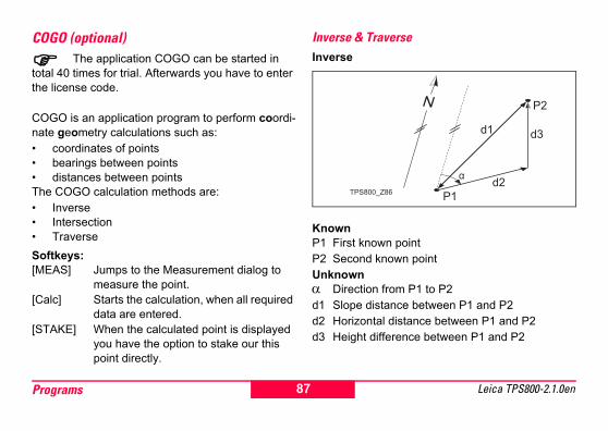
COGO (optional)The application COGO can be started in
total 40 times for trial. Afterwards you have to enter the license code.
COGO is an application program to perform coordi-nate geometry calculations such as:• coordinates of points• bearings between points• distances between pointsThe COGO calculation methods are:• Inverse• Intersection• TraverseSoftkeys:[MEAS] Jumps to the Measurement dialog to
measure the point.[Calc] Starts the calculation, when all required
data are entered.[STAKE] When the calculated point is displayed
you have the option to stake our this point directly.
Inverse & TraverseInverse
KnownP1 First known pointP2 Second known pointUnknownα Direction from P1 to P2d1 Slope distance between P1 and P2d2 Horizontal distance between P1 and P2d3 Height difference between P1 and P2
TPS800_Z86
d1d3
d2
P1
P2
87Programs Leica TPS800-2.1.0en

Traverse
KnownP1 Known pointα Direction from P1 to P2d1 Distance between P1 and P2d2 Positive offset to the rightd3 Negative offset to the leftUnknownP2 COGO point without offsetP3 COGO point with positive offsetP4 COGO point with negative offset
IntersectionsBearing - Bearing
KnownP1 First known pointP2 Second known pointα1 Direction from P1 to P3α2 Direction from P2 to P3UnknownP3 COGO point
TPS800_Z87
d1
d2
d3
P1
P3
P2P4
TPS800_Z88
P1
P2
P31
2
88 ProgramsLeica TPS800-2.1.0en

Bearing - Distance
KnownP1 First known pointP2 Second known pointα Direction from P1 to P3 and P4r Radius, as defined by the distance from P2 to
P4 and P3UnknownP3 First COGO pointP4 Second COGO point
Distance - Distance
KnownP1 First known pointP2 Second known pointr1 Radius, as defined by the distance from P1 to
P3 or P4r2 Radius, as defined by the distance from P2 to
P3 or P4UnknownP3 First COGO pointP4 Second COGO point
TPS800_Z89
r
P1
P2
P4
P3
TPS800_Z90
r1
r2
P1
P2P3
P4
89Programs Leica TPS800-2.1.0en

By Points
KnownP1 First known pointP2 Second known pointP3 Third known pointP4 Fourth known pointa Line from P1 to P2b Line from P3 to P4UnknownP5 COGO point
OffsetDistance - Offset
KnownP1 Baseline start pointP2 Baseline end pointP3 Lateral pointUnknowna Difference in length/abzissa (HD)b Lateral deviation/ordinate (Offset)P4 Base point
TPS800_Z91
a
b
P1
P2
P3
P4
P5
TPS800_Z92
d1
d2
P1
P2
P3
P4
90 ProgramsLeica TPS800-2.1.0en

Set Point by ...
KnownP1 Baseline start pointP2 Baseline end pointa Difference in length/abzissa (HD)b Lateral deviation/ordinate (Offset)UnknownP3 Lateral point
ExtentionThe "Extention" routine computes extend point from base line.
KnownP1 Baseline start pointP3 Baseline end point
L1 or L2 DistanceUnknownP2, P4 Extended point
TPS800_Z93
b
a
P1
P2
P3
TPS800_Z94
P1
P2
P3
P4
ΔL1
ΔL2
91Programs Leica TPS800-2.1.0en

CodingCodes contain information about recorded points. With the help of coding, points can be assigned to a particular group simplifying later processing.More information on coding can be found under "Data management".GSI-codingCode: Code nameDesc.: Additional remarkInfo1: more, freely editable ... informationInfo8: linesProcedure:1. Move cursor to field "Code".2. Input code.3. [ALL] Starts the distance measurement
and saves the values including the entered code.
[CODE] Searches for the entered code and offers the option of adding attributes.
[SET] Sets the code block.[AddList] Adds an entered code into codelist.[RECORD] Closes the code entry or code selection
and saves the code block.
AddList RECORD SET
Find: T*
Code: TR1
Desc: Border Line
CODE (FIND/SELECT)
92 ProgramsLeica TPS800-2.1.0en

Manual code inputIndividual code blocks can be entered directly via keypad.
1. [INPUT] Enter desired code.
2. Confirm with ENTER.3. Enter the attributes 1-8.
4. [SET] Sets the code block.
Extending / editing code1. Call available code from code list.2. Attributes can be overwritten freely.Exceptions:With the codelist editor of LGO a status can be assi-gned to the attributes.• Attributes with "fixed status" (see LGO) are
write-protected. They cannot be overwritten or edited.
• For attributes with status "Mandatory" an input or a confirmation is required.
• Attributes with status "Normal" can be edited freely.
Recording code block[SET] Sets the code block temporarily in the systemafter ending the code functions. Recording only with measurement and always with reference to the actual point number.
INPUT SET
Info1 : ------
Info2 : ------
Info3 : ------
Info4 : ------
ATTRIBUTE ENTRY
93Programs Leica TPS800-2.1.0en

Quick CodeUsing the quick code function, a predefined code can be called directly via the numeric keypad on the instrument. The code is selected by entering a two digit number, the measurement triggered and the measured data and code saved.A total of 100 codes can be assigned.Each code can be assigned a unique one or two digit number in the "Codelist Manager".
If no numbers are allocated to the codes in the "Codelist Manager", the code is selected in accor-dance with the order in which the codes were entered in the code list (01 -> first code in the code list ... 10 -> tenth code in the code list).
Procedure:1. Press the [Q-Code] button to activate Quick
coding.2. Enter a two digit number on the numeric keypad
-> code is selected, the measurement triggered and the measured data and code saved.
The name of the selected code is displayed after the measurement.
A two digit code must always be entered on the instrument's numeric keypad even if only a one digit code was assigned in the Codelist Manager.For example: 4 -> enter 04.
To end Q-Coding press the [Q-Code] button again.
94 ProgramsLeica TPS800-2.1.0en

Warnings / Messages
Individually entered code blocks are not added to the code list.Leica Geo Office Tools (LGO-Tools)Codelists can be easily created and uploaded to the instrument using the supplied "LGO-Tools" Soft-ware.
Important Messages Meaning
Attrib. cannot be changed !
Attribute with fixed status cannot be changed.
No codelist available !No codelist in memory. Manual input for code and attributes are called automatically.
Entry required ! Code missing. Extend input.
95Programs Leica TPS800-2.1.0en

SettingsThis menu enables extensive user-specific settings in order to adapt the instrument to their own require-ments.ContrastSetting the display contrast in 10% steps.Trigger keyConfiguration of the trigger key on side cover.Off Trigger key deactivated.ALL Trigger key with same function as
the [ALL]-key.DIST Trigger key with same function as
the [DIST]-key.USER KeyConfigure the USER Key with a function from the FNC-menu.V-SettingThe "0"- orientation of the vertical circle can be either selected for the zenith, the horizontal plane or in %.
• Zenith:Zenith=0°; Horizon=90°• Horizon: Zenith=90°; Horizon=0°• V-(%): 45°=100%; Horizon=0°
The % value increases rapidly. "--.--%" appears on the display above 300%".Tilt CorrectionOff Tilting compensation switched off.1-axis V-angles relate to the plumb line.2-axis V-angle refer to the plummet line and
the Hz-directions are corrected by the standing axis tilt.
If the instrument is used on an unstable base (e.g. shaking platform, ship, etc.) the compensator should be switched off.This avoids the compensator drifting out of it's measuring range and interupting the measuring process by indicating an error.
The compensator setting remains active even after the instrument is switched off.
96 SettingsLeica TPS800-2.1.0en

Sector Beep Off Sector Beep switched offOn Sector Beep sounds at right angles (0°,
90°, 180°, 270° or 0, 100, 200, 300 gon)Example Sector Beep:From 95.0 to 99.5 gon (or from 105.0 to 100.5 gon) a "Fast beep" sounds whilest from 99.5 to 99.995 gon (or from 100.5 to 100.005 gon) a "Permanent beep" sounds.
1) No beep2) Fast beep (interrupted)3) Permanent beep
TPS800_Z45
97Settings Leica TPS800-2.1.0en

BeepThe beep is an acoustic signal after each key stroke.Off Beep switched offNormal Normal volumeLoud Increased volumeHz IncrementationRight Set right Hz for "Clockwise direction
measurement".Left Set left Hz for "Counter-clockwise direc-
tion measurement". "Counter-clock-wise" directions are only displayed but saved as "Clockwise direction".
Reticle IlluminationThe reticle illumination is only switched on if the display illumination is on.Low Low illuminatonMedium Medium illuminaton High High illuminaton
Display HeaterOn Is automatically activated when the
display illumination is on and the instru-ment temperature is ≤ 5°C.
Data OutputRS232 Data is recorded via the serial interface.
For this purpose, a data storage device must be connected.
Intern All data is recorded in the internal memory.
GSI 8/16Select GSI output format.GSI 8: 81..00+12345678GSI 16: 81..00+1234567890123456Mask 1/2Select GSI output mask.Mask 1: PtID, Hz, V, SD, ppm+mm, hr, hiMask 2: PtID, Hz, V, SD, E, N, H, hr
98 SettingsLeica TPS800-2.1.0en

Hz CollimationOn Hz Collimation is switched ON. Off Hz Collimation is switched OFF. If option "Hz Collimation ON" is active, each measured Hz-angle is corrected (depending on V-angle). For normal operation the Hz-collimation remains switched on.
More information on Hz-collimation can be found under "Adjustments".Auto-OFFEnable The instrument is switched off after 20
minutes without any action (= no key pressed; V and Hz angle deviation ≤ ±3' / ±600cc).
Disable The instrument is switched on perma-nently. Battery discharges quicker.
Sleep Economy mode. Instrument is recov-ered by any key stroke.
Min. ReadingThe displayed angle format can be selected in three steps.• For 360°'":
0° 00' 01" / 0° 00' 05" / 0° 00' 10"Always " are indicated.
• For 360°:0.0005° / 0.001° / 0.0001°
• For gon:0.0005 gon / 0.001 gon / 0.0001 gon
• For mil:0.01 mil / 0.05 mil / 0.10 mil
99Settings Leica TPS800-2.1.0en

Angle Unit° ' " (degree sexagesimal)
possible angle values: 0° to 359°59'59''
DD (degree decimal)possible angle values: 0° to 359.999°
gon possible angle values: 0 gon to 399.999 gon
mil possible angle values: 0 to 6399.99mil
The setting of the angle units can be changed at any time.The actual displayed values are converted accor-ding to the selected unit.Distance Unitmeter Meterft-in1/16 US-feet-Inch-1/16 inchUS-ft US-feetINT-ft International feet
Temperature°C Degree Celsius°F Degree FahrenheitPressurembar MillibarhPa Hecto PascalmmHg Millimeter mercury columninHg Inch mercury columnFace I DefinitionDefines the telescope face I in relation to the posi-tion of the Vdrive.Code RecordSets if the codeblock is saved before or after the measurement (see chapter "Coding").
100 SettingsLeica TPS800-2.1.0en

EDM SettingsThe EDM-settings contain a detailed menu with selection boxes.
EDM ModeWith TCR instruments different settings for measu-rements with reflectorless (RL) and reflector mode (IR) EDM type are available.Depending on selected measuring mode the selec-tion prism types are different.
IR-FineFine measuring mode for high precision measurements with prisms(2mm + 2 ppm)
IR-FastQuick measuring mode with higher measuring speed and reduced accuracy (5mm + 2 ppm)
IR-TrackContinuous distance measuring (5mm + 2 ppm)
IR-TapeDistance measurement using Retro targets(5mm + 2 ppm)
101EDM Settings Leica TPS800-2.1.0en

With the RL-EDM each object in the beam is measured (possibly also branches, cars, etc.).Prism typeCalling the function in the EDM settings.
RL-ShortShort range. For distance measurements without prisms (3mm + 2 ppm)
RL-TrackContinuous distance measure-ment without prisms(5mm + 2 ppm)
RL-PrismLong range. For distance measurements with prisms (5mm + 2 ppm)
Leica Prisms
Constants[mm]
Standard prism (Round)GPH1 +GPR1
0.0
360° prism GRZ4 +23.1
360° Mini prismGRZ101 +30.0
MiniprismGMP101/102 +17.5
JPMINI +34.4 Mini prismReflective targets +34.4
USER --is set at "Prismconst" (-mm + 34.4; e.g.: mm = 14 -> input = -14 + 34.4 = 20.4)
RL +34.4 Reflectorless
Leica Prisms
Constants[mm]
102 EDM SettingsLeica TPS800-2.1.0en
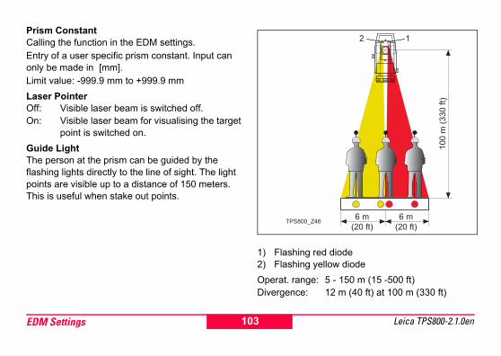
Prism ConstantCalling the function in the EDM settings.Entry of a user specific prism constant. Input can only be made in [mm].Limit value: -999.9 mm to +999.9 mmLaser PointerOff: Visible laser beam is switched off.On: Visible laser beam for visualising the target
point is switched on.Guide Light The person at the prism can be guided by the flashing lights directly to the line of sight. The light points are visible up to a distance of 150 meters. This is useful when stake out points.
1) Flashing red diode 2) Flashing yellow diodeOperat. range: 5 - 150 m (15 -500 ft)Divergence: 12 m (40 ft) at 100 m (330 ft)
TPS800_Z46
103EDM Settings Leica TPS800-2.1.0en

[SCALE]Scale of projection.
Scale factor:Entering the scale of projection. Measured values and coordinates are corrected with the PPM para-meter.[PPM=0] Sets default parameters.[PPM]Input of individual scaling parameters.
[ATMOS]Input of atmospheric parameters.
Atmospheric Parameters (ppm):Distance measurement is influenced directly by the atmospheric conditions of the air in which distance measurement are taken.
In order to take into consideration these influences distance measurements are corrected using atmospheric correction parameters.
PREV PPM=0 OK
Scale factor: 1.000060
Scale ppm : 60
PROJECTION SCALE
Enter scale factor !
INPUT PREV PPM=0 SET
Ht. a. MSL : 500 mTemperature: 16 °CPressure : 952 hPaAtmos PPM : 21 PPM
ATMOSPHERIC DATA (PPM)
104 EDM SettingsLeica TPS800-2.1.0en

• Ht. a. MSLHeight above sea level at instrument location.
• TemperatureAir temperature at instrument location.
• Pressure Air pressure at instrument location.
• Atmos PPM:Calculated and indicated atmospheric PPM.
• Refr.Coeff:Input of refraction coefficient for the atmospheric conditions.
Refraction correctionThe refraction correction is taken into account in the calculation of the height differences and the hori-zontal distance.Signal[SIGNAL] Displays EDM signal strength (reflection
strength) in steps of 1%. Permits optimal aiming at distant barely visible targets.
105EDM Settings Leica TPS800-2.1.0en

File ManagementThe File Manager contains all functions for entering, editing and for checking data in the field.
JobJobs are a summary of data of different types, e.g. fixed points, measurements, codes, results, etc.The job definition consists of the input of job name and user. Additionally, the system generates time and date at the time of creation.Job search:
Scrolling through jobs.
[DELETE] Deletes selected job.
[SET] Sets the selected job.
[NEW] Starts new job.
F1 F2 F3 F4
F1 Job
F2 Fixpoints
F3 Measurements
F4 Codes
FILE MANAGEMENT 1
F1 Initialize Memory
F2 Memory Statistic
FILE MANAGEMENT 2
106 File ManagementLeica TPS800-2.1.0en

FixpointsValid fixed points contain at least the PtID and the coordinates (E, N) or (H).[DELETE] Deletes selected fixed point.[FIND] Starts point search. Exact PtIDs can
be entered or the * wildcard-criteria used.
[NEW] Opens input for PtID and coordi-nates.
MeasurementsMeasurement data available in the internal memory can be searched and displayed or erased.[FIND] Starts point search dialogue.[VIEW] Displays all measurements.CodesTo each code a description and a maximun of 8 attri-butes with up to 16 characters can be assigned. [SAVE] Save data.
[VIEW] Starts search dialogue.[ATTRIB] Input of attributes.
SAVE VIEW ATTRIB
Code: Nr01Desc: border line
INPUT CODELIST
Info1: Nr. 123 Info2: 12.54 Info3:
107File Management Leica TPS800-2.1.0en

Initialize MemoryDeletes jobs, single data areas of a job or alldata.[DELETE] Starts deleting process within the
selected area.[ALL] Deletes all data in memory. All data
will be lost !Deleting the memory cannot be undone.
After confirming the message all data is deleted permanently.Memory StatisticDisplays job specific memory information such as:• Number of stored fixpoints.• Number of recorded data blocks (measured
points, codes, etc.).• Number of free or not defined jobs.
108 File ManagementLeica TPS800-2.1.0en

Start-up sequenceSets the screen the instrument starts in when swit-ched on. E.g. the electronic bubble can be displayed at every start.
[OK] Stores current settings.[RECORD] Defines the key presses that are
executed automatically upon start up.[Play] Starts to run the recorded sequence.
Procedure:After confirming the dialogue of notification, the "Meas & Rec" screen is displayed. A maximum of 16 of the next key presses are stored. The sequence is ended with [ESC]. If the start sequence is activated, the stored key presses are executed automatically when the instrument is switched on.
The automatic start sequence has the same effect as pressing the keys manually. Certain instru-ment settings can not be made in this way. "Relative entries" such as automatically setting "IR-FINE" upon switching on the instrument, are not possible.
RECORD Play OK
Press F1 to start recording
a new sequence
Start-Up: enabled
START-UP SEQUENCE
109Start-up sequence Leica TPS800-2.1.0en

Check & AdjustDetermining Line-of-sight error and V-IndexThe adjustment contains the determination of the following instrument errors:• Hz-collimation• V-index (simultaneously electronic level)For determining the Hz-collimation or the V-index it is necessary to measure in both telescope positions. The procedure can be started in any telescope posi-tion. The user is guided clearly through the procedure. A wrong determination of instrument error is thus eliminated.The instruments are adjusted in the factory prior to shipping.Instrument errors can change with time and tempe-rature.
These errors should be determined before the instrument is used for the first time, before preci-sion surveys, after long periods of transport, before and after long periods of work, and if the tempera-ture changes by more than 10°C (18°F).
Before determining the instrument errors, level-up the instrument using the electronic bubble. The instrument should be secure and firm, and should be
protected from direct sunlight in order to avoid thermal expansion on one side only.
Before starting to work, the instrument has to become acclimatised to the ambient temperature. Approximately two minutes per °C of temperature difference from storage to working environment but at least 15 min should be taken into account.
110 Check & AdjustLeica TPS800-2.1.0en

Line-of-sight error (Hz-collimation)
The line-of-sight error or collimation error (C) is the deviation from the perpendicular between the tilting axis and the line of sight.The effect of the line-of-sight error to the Hz-angle increases with the vertical angle.For horizontal aimings the error of Hz equals the line-of-sight error.
V-Index (Vertical index error)
The vertical circle should read exactly 90° (100 gon) when the line of sight is horizontal. Any deviation from this figure is termed vertical index error (i).By determining the vertical index error the electronic level is adjusted automatically.
Procedures and conditions required to correct line-of-sight and height index errors are the same. Thus the procedure will only be described once.
TPS800_Z47 TPS800_Z48
111Check & Adjust Leica TPS800-2.1.0en

Hz-collimationV-indexDisplay adjustment value: Summarizes saved values.
Procedure:1. Level instrument with electronic bubble. 2. Aim at a point approximately 100m from the
instrument which is within 5° of the horizontal.
3. [ALL]: Trigger measurement.4. Change telescope position and aim to the point
again.
For checking the horiontal aiming Hz and V are displayed.
5. [ALL]: Starts measurement6. Displays the old and new calculated values.
[SET] Sets new adjustment data.[ESC] Quits program without setting new
adjustment data.TPS800_Z49
TPS800_Z50
112 Check & AdjustLeica TPS800-2.1.0en
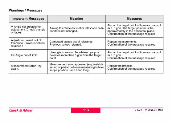
Warnings / Messages
Important Messages Meaning Measures
V-Angle not suitable for adjustment (Check V-angle or face) !
Aiming tolerance not met or telescope posi-tion/face not changed.
Aim on the target point with an accuracy of min. 5 gon. The target point must be approximately in the horizontal plane.Confirmation of the message required.
Adjustment result out of tolerance. Previous values retained !
Computed values out of tolerance. Previous values retained.
Repeat measurements.Confirmation of the message required.
Hz-Angle out of limit !Hz-angle in second face/telescope pos. deviates more than 5 gon from the target point.
Aim on the target point with an accuracy of min. 5 gon. Confirmation of the message required.
Measurement Error. Try again.
Measurement error appeared (e.g. instable set up or period between measuring in tele-scope position I and II too long).
Repeat the process.Confirmation of the message required.
113Check & Adjust Leica TPS800-2.1.0en

Tripod
The connections between metal and timber components must always be firm and tight.• Tighten the Allen screws (2) moderately.• Tighten the articulated joints on the tripod head
(1) just enough to keep the tripod legs open when you lift it off the ground.
Circular level
Level-up the instrument in advance with the elec-tronic level. The bubble must be centered. If it extends beyond the circle, use the Allen key supp-lied to center it by turning the adjustment screws.After adjustment no screw must be loose.
TPS800_Z56TPS800_Z57
114 Check & AdjustLeica TPS800-2.1.0en

Circular level on the tribrach
Level the instrument and then remove it from the tribrach. If the bubble is not centred, adjust it using the adjusting pin.Turning the adjustment screws:• to the left: the bubble approaches the screw • to the right: the bubble goes away from the
screw.After adjustment no screw must be loose.
Laser plummetThe laser plummet is integrated into the vertical axis of the instrument. Under normal circumstances setting of the laser plummet is not necessary. If an adjustment is necessary due to external influences the instrument has to be returned to any Leica service department.
Checking by turning the instrument by 360°:1. Install the instrument on the tripod approx. 1.5 m
above ground and level up.2. Switch on laser plummet and mark the centre of
the red spot.3. Turn instrument slowly by 360° and observe the
red laser dot.Inspecting the laser plummet should be carried out on a bright, smooth and horizonal surface (e.g. a sheet of paper).If the centre of the laser dot makes a clearly circular movement or if the centre of the point is moving away more than 3 mm from the first marked point an adjustment is possibly necessary. Call your nearest Leica service department.
TPS800_Z58
115Check & Adjust Leica TPS800-2.1.0en

Depending on brightness and surface the size of the laser dot can vary. At a distance of 1.5 m an average value of 2.5 mm diameter must be estimated.The maximum diameter of the circular movement described by the centre of the laser point should not exceed 3 mm at a distance of 1.5m.
Chapter validity
Reflectorless EDMThe red laser beam used for measuring without reflector is arranged coaxially with the line of sight of the telescope, and emerges from the objective port. If the instrument is well adjusted, the red measuring beam will coincide with the visual line of sight. External influences such as shock or large tempera-ture fluctuations can displace the red measuring beam relative to the line of sight.
The direction of the beam should be inspected before precise measurement of distances is attempted, because an excessive deviation of the laser beam from the line of sight can result in impre-cise distance measurements.
TPS800_Z59
This chapter is relevant for Telescope Type 1 only.
116 Check & AdjustLeica TPS800-2.1.0en

� Warning For safety aspects direct intrabeam viewing
should be considered always as hazardous.Precautions:Do not stare into the beam or direct it towards other people unnecessarily. These measures are also valid for the reflected beam.
InspectionA target plate is provided. Set it up between five and 20 metres away with the grey reflective side facing the instrument. Move the telescope to face II. Switch on the red laser beam by activating the laser-point function. Use the telescope crosshair to align the instrument with the centre of the target plate, and then inspect the position of the red laser dot on the target plate. Generally speaking the red spot cannot be seen through the telescope, so look at the target plate from just above the telescope or from just to the side of it.If the spot illuminates the cross, the achievable adju-stment precision has been reached; if it lies outside the limits of the cross, the direction of the beam needs to be adjusted.
If the spot on the more reflective side of the plate is too bright (dazzling), use the white side instead to carry out the inspection.
Adjusting the direction of the beamPull the two plugs out from the adjustment ports on the top side of the telescope housing. To correct the height of the beam, insert the screwdriver into the rear adjustment port and turn it clockwise (spot on target plate moves obliquely upwards) or anticlockwise (spot moves obliquely downwards).
TPS800_Z60
117Check & Adjust Leica TPS800-2.1.0en

To correct the beam laterally, insert the screwdriver into the front adjustment port and turn it clockwise (spot moves to the right) or anticlockwise (spot moves to the left).
Throughout the adjustment procedure, keep the telescope pointing to the target plate.
After each field adjustment, replace the plugs in the adjustment ports to keep out damp and dirt.
TPS800_Z61
TPS800_Z62
118 Check & AdjustLeica TPS800-2.1.0en

COMM ParametersFor data transfer between PC and instrument the communication parameters of the serial interface RS232 must be set.Leica Standard setting19200 Baud, 8 Databit, No Parity, 1 Stopbit, CR/LFBaudrateData transfer speed 2400, 4800, 9600, 19200 [bits / second]Databits7 Data transfer is realized with 7 databits. Is set
automatically if parity is "Even" or "Odd".8 Data transfer is realized with 8 databits. Is set
automatically if parity is "None".ParityEven Even parityOdd Odd parityNone No parity (if data bit is set to 8)EndmarkCRLF Carriage return; line feed
CR Carriage returnStopbitsFixed setting 1.Interface plug connections:
1) External battery2) Not connected / inactive3) GND 4) Data reception (TH_RXD)5) Data transfer (TH_TXD)
TH ... Theodolite
TPS800_Z51
2
345
1
119COMM Parameters Leica TPS800-2.1.0en

Data TransferWith this special function measured data can be trans-fered via the serial interface to a receiver (e.g. a Laptop). Using this type of transfer the success of the transfer is not checked.Job: Selection of job from which data should
be transfered.Data: Select the data range to be transferred
(measurements, fixed points)Format: Select output format. Select Leica-GSI-
format, or your own format created in the "Format Manager" and transfer to the LGO.
[SEND] Starts the transmission.
Example:Within the "data" setting "MEASUREMENTS" a data set could be shown as follows:11....+00000D19 21..022+1664182622..022+09635023 31..00+0000664958..16+00000344 81..00+0000334282..00-00005736 83..00+00000091
87..10+00001700If the receiver is to slow in processing data
the data could be lost. With this type of data transfer the instrument is not informed about the perfor-mance of the receiver (no protocol).GSI-ID’s11 PtID21 Horizontal direction22 Vertical angle31 Slope distance32 Horizontal distance33 Height difference41-49 Codes and attributes51 ppm [mm]58 Prism constants81-83 (E, N, H) Target point84-86 (E, N, H) Stand point87 Reflector height88 Instrument height
120 Data TransferLeica TPS800-2.1.0en

System InfoDisplays helpful information and date / time are set.
• BatteryRemaining battery power (e.g. 40%).
• Instr.Temp.Measured instrument temperature.
• DateDisplays the current date.
• TimeDisplays current time.
[DATE] Change date and format.Format: There are three display formats:• DD.MM.YYYY• MM.DD.YYYY• YYYY.MM.DDTDate: Input date
[TIME] Set time.
[SW-Info] The software of the instrument is composed of different software pack-ages. Depending on the package, different versions are possible.Op-System: Operating SystemApp.-SW: Applications, functions
and menuLayout: User displays
121System Info Leica TPS800-2.1.0en

Instrument Protection with PINThe instrument can be protected by a Personal Identification Number. If the PIN protection is acti-vated, the instrument will always prompt for a PIN code entry after starting up. If a wrong PIN has been typed in five times, a Personal UnblocKing code is required which can be found on the instrument deli-very papers. If the PUK code entered is correct then the old PIN code is set to default value "0" and the PIN protection is deactivated.Procedure: 1. [MENU] > [PIN]2. Activate PIN by setting <Use PIN Code>: On.3. Enter your desired personal PIN Code (max. 6
character numeric) and accept with [OK].
Now the instrument is protected against unauthorized use. After switching on the instrument the PIN Code entry is necessary.
If the PIN protection is activated you can furthermore lock the instrument from any applica-tion by pressing [FNC] > Lock with PIN without switching off the instrument
122 Instrument Protection with PINLeica TPS800-2.1.0en

Care and Transport
TransportTransport in the fieldWhen transporting the equipment in the field, always make sure that you• either carry the product
in its original transport container,
• or carry the tripod with its legs splayed across your shoulder, keeping the attached product upright.
Transport in a road vehicleNever carry the product loose in a road vehicle, as it can be affected by shock and vibration. Always carry the product in its transport container and secure it.
ShippingWhen transporting the product by rail, air or sea, always use the complete original Leica Geosystems packaging, transport container and cardboard box, or its equivalent, to protect against shock and vibra-tion.
Shipping, transport of batteriesWhen transporting or shipping batteries, the person in charge of the product must ensure that the appli-cable national and international rules and regula-tions are observed. Before transportation or ship-ping, contact your local passenger or freight trans-port company.
Field adjustmentAfter transport inspect the field adjustment parame-ters given in this user manual before using the product.
TPS800_Z52
123Care and Transport Leica TPS800-2.1.0en

StorageProductRespect the temperature limits when storing the equipment, particularly in summer if the equipment is inside a vehicle. Refer to "Technical Data" for information about temperature limits.
Field adjustmentAfter long periods of storage inspect the field adjust-ment parameters given in this user manual before using the product.
Batteries• Refer to "Technical Data" for information about
storage temperature range.• The permissible temperature range for storing is
-40°C to +55°C / -40°F to +131°F. We recom-mend a storage temperature range of 0°C to +20°C / +32°F to 68°F in dry environment to minimize self-discharging.
• At the recommended storage temperature range, batteries containing a 10% to 50% charge can be stored for up to one year. After this storage period the batteries must be recharged.
• Remove batteries from the product and the charger before storing.
• After storage recharge batteries before using.• Protect batteries from damp and wetness. Wet
or damp batteries must be dried before storing or use.
124 Care and TransportLeica TPS800-2.1.0en

Cleaning and DryingObjective, eyepiece and prisms• Blow dust off lenses and prisms.• Never touch the glass with your fingers.• Use only a clean, soft, lint-free cloth for
cleaning. If necessary, moisten the cloth with water or pure alcohol.Do not use other liquids; these may attack the polymer components.
Fogging of prismsReflector prisms that are cooler than the ambient temperature tend to fog. It is not enough simply to wipe them. Keep them for some time inside your jacket or in the vehicle to allow them to adjust to the ambient temperature.
Damp productsDry the product, the transport container, the foam inserts and the accessories at a temperature not greater than 40°C / 108°F and clean them. Do not repack until everything is completely dry.
Cables and plugsKeep plugs clean and dry. Blow away any dirt lodged in the plugs of the connecting cables.
TPS800_Z55
125Care and Transport Leica TPS800-2.1.0en

Safety DirectionsThe following directions should enable the person responsible for the product, and the person who actually uses the equipment, to anticipate and avoid operational hazards.
The person responsible for the product must ensure that all users understand these directions and adhere to them.
Intended UsePermitted use• Measuring horizontal and vertical angles.• Measuring distances.• Recording measurements.• Computing by means of application software.• Visualizing the aiming direction and vertical axis.• Visualizing the target (with laser pointer).
Adverse use• Use of the product without instruction.• Use outside of the intended limits.• Disabling safety systems.• Removal of hazard notices.• Opening the product using tools, for example
screwdriver, unless this is specifically permitted for certain functions.
• Modification or conversion of the product.• Use after misappropriation.
126 Safety DirectionsLeica TPS800-2.1.0en

• Use of products with obviously recognizable damages or defects.
• Use with accessories from other manufacturers without the prior explicit approval of Leica Geosystems.
• Aiming directly into the sun.• Inadequate safeguards at the surveying site, for
example when measuring on roads.• Deliberate dazzling of third parties.• Controlling of machines, moving objects or
similar monitoring application without additional control- and safety installations.
� WarningAdverse use can lead to injury, malfunction
and damage.It is the task of the person responsible for the equip-ment to inform the user about hazards and how to counteract them. The product is not to be operated until the user has been instructed on how to work with it.
Limits of UseEnvironmentSuitable for use in an atmosphere appropriate for permanent human habitation: not suitable for use in aggressive or explosive environments.
� DangerLocal safety authorities and safety experts
must be contacted before working in hazardous areas, or in close proximity to electrical installations or similar situations by the person in charge of the product.
127Safety Directions Leica TPS800-2.1.0en

ResponsibilitiesManufacturer of the productLeica Geosystems AG, CH-9435 Heerbrugg, hereinafter referred to as Leica Geosystems, is responsible for supplying the product, including the user manual and original accessories, in a comple-tely safe condition.Manufacturers of non Leica Geosystems acces-soriesThe manufacturers of non Leica Geosystems acces-sories for the product are responsible for developing, implementing and communicating safety concepts for their products, and are also responsible for the effectiveness of those safety concepts in combination with the Leica Geosystems product.
Person in charge of the productThe person in charge of the product has the follo-wing duties:• To understand the safety instructions on the
product and the instructions in the user manual.• To be familiar with local regulations relating to
safety and accident prevention.• To inform Leica Geosystems immediately if the
product and the application becomes unsafe.
� WarningThe person responsible for the product must
ensure that it is used in accordance with the instruc-tions. This person is also accountable for the training and the deployment of personnel who use the product and for the safety of the equipment in use.
128 Safety DirectionsLeica TPS800-2.1.0en

International Waranty, Software Li-cence AgreementInternational WarantyThe International Warranty can be downloaded from the Leica Geosystems AG home page at http://www.leica-geosystems.com/internationalwarrantyor received from your Leica Geosystems dealer.Software Licence AgreementThis product contains software that is preinstalled on the product, or that is supplied to you on a data carrier medium, or that can be downloaded by you online pursuant to prior authorization from Leica Geosystems. Such software is protected by copy-right and other laws and its use is defined and regu-lated by the Leica Geosystems Software Licence Agreement, which covers aspects such as, but not limited to, Scope of the Licence, Warranty, Intellec-tual Property Rights, Limitation of Liability, Exclusion of other Assurances, Governing Law and Place of Jurisdiction. Please make sure, that at any time you
fully comply with the terms and conditions of the Leica Geosystems Software Licence Agreement.
Such agreement is provided together with all products and can also be found at the Leica Geosy-stems home page at http://www.leica-geosystems.com/swlicenseor your Leica Geosystems dealer.
You must not install or use the software unless you have read and accepted the terms and conditions of the Leica Geosystems Software Licence Agree-ment. Installation or use of the software or any part thereof, is deemed to be an acceptance of all the terms and conditions of such licence agreement. If you do not agree to all or some of the terms of such licence agreement, you may not download, install or use the software and you must return the unused software together with its accompanying documen-tation and the purchase receipt to the dealer from whom you purchased the product within ten (10) days of purchase to obtain a full refund of the purchase price.
129Safety Directions Leica TPS800-2.1.0en

Hazards of use
� WarningThe absence of instruction, or the inadequate
imparting of instruction, can lead to incorrect or adverse use, and can give rise to accidents with far-reaching human, material, financial and environ-mental consequences.Precautions:All users must follow the safety directions given by the manufacturer and the directions of the person responsible for the product.
� CautionWatch out for erroneous measurement
results if the product has been dropped or has been misused, modified, stored for long periods or trans-ported.Precautions:Periodically carry out test measurements and perform the field adjustments indicated in the user manual, particularly after the product has been
subjected to abnormal use and before and after important measurements.
� DangerBecause of the risk of electrocution, it is very
dangerous to use poles and extensions in the vicinity of electrical installations such as power cables or electrical railways.Precautions:Keep at a safe distance from electrical installations. If it is essential to work in this environment, first contact the safety authorities responsible for the electrical installations and follow their instructions.
� WarningBy surveying during a thunderstorm you are
at risk from lightening.Precautions:Do not carry out field surveys during thunderstorms.
130 Safety DirectionsLeica TPS800-2.1.0en

� CautionBe careful when pointing the product towards
the sun, because the telescope functions as a magnifying glass and can injure your eyes and/or cause damage inside the product.Precautions:Do not point the product directly at the sun.
� WarningDuring dynamic applications, for example
stakeout procedures there is a danger of accidents occurring if the user does not pay attention to the environmental conditions around, for example obstacles, excavations or traffic.Precautions:The person responsible for the product must make all users fully aware of the existing dangers.
� WarningInadequate securing of the surveying site can
lead to dangerous situations, for example in traffic, on building sites, and at industrial installations.
Precautions:Always ensure that the survey site is adequately secured. Adhere to the regulations governing safety and accident prevention and road traffic.
� WarningIf computers intended for use indoors are
used in the field there is a danger of electric shock.Precautions:Adhere to the instructions given by the computer manufacturer with regard to field use in conjunction with Leica Geosystems products.
� CautionIf the accessories used with the product are
not properly secured and the product is subjected to mechanical shock, for example blows or falling, the product may be damaged or people may sustain injury.Precautions:When setting-up the product, make sure that the accessories, for example tripod, tribrach, connecting
131Safety Directions Leica TPS800-2.1.0en

cables, are correctly adapted, fitted, secured, and locked in position.Avoid subjecting the product to mechanical stress.
� CautionDuring the transport, shipping or disposal of
batteries it is possible for inappropriate mechanical influences to constitute a fire hazard.Precautions:Before shipping the product or disposing of it, discharge the batteries by running the product until they are flat.When transporting or shipping batteries, the person in charge of the product must ensure that the appli-cable national and international rules and regula-tions are observed. Before transportation or ship-ping contact your local passenger or freight trans-port company.
� WarningUsing a battery charger not recommended by
Leica Geosystems can destroy the batteries. This can cause fire or explosions.
Precautions:Only use chargers recommended by Leica Geosy-stems to charge the batteries.
� WarningHigh mechanical stress, high ambient
temperatures or immersion into fluids can cause leackage, fire or explosions of the batteries.Precautions:Protect the batteries from mechanical influences and high ambient temperatures. Do not drop or immerse batteries into fluids.
� WarningShort circuited battery terminals can overheat
and cause injury or fire, for example by storing or transporting in pockets if battery terminals come in contact with jewellery, keys, metallized paper or other metals.Precautions:Make sure that the battery terminals do not come into contact with metallic objects.
132 Safety DirectionsLeica TPS800-2.1.0en

� WARNINGIf the product is improperly disposed of, the
following can happen:• If polymer parts are burnt, poisonous gases are
produced which may impair health.• If batteries are damaged or are heated strongly,
they can explode and cause poisoning, burning, corrosion or environmental contamination.
• By disposing of the product irresponsibly you may enable unauthorized persons to use it in contravention of the regulations, exposing them-selves and third parties to the risk of severe injury and rendering the en-vironment liable to contamination.
• Improper disposal of silicone oil may cause environmental contamination.
Precautions:The product must not be disposed with household waste. Dispose of the product appropriately in accordance with the national regula-tions in force in your
country. Always prevent access to the product by unauthorized personnel.
Product specific treatment and waste management information can be downloaded from the Leica Geosystems home page at http://www.leica-geosy-stems.com/treatment or received from your Leica Geosystems dealer.
� WarningOnly Leica Geosystems authorized service
workshops are entitled to repair these products.
133Safety Directions Leica TPS800-2.1.0en

Laser Classification
Integrated Distancer, Measurements with Reflectors (IR mode)
The product is a Class 1 Laser Product in accor-dance with:• IEC 60825-1 (2001-08): "Safety of Laser Prod-
ucts"• EN 60825-1:1994 + A11:1996 + A2:2001:
"Safety of Laser Products"Class 1 Laser Products are safe under reasonably foreseeable conditions of operation and are not harmful to the eyes provided that the products are used and maintained in accordance with the instruc-tions.
The EDM module built into the product produces an invisible laser beam which emerges from the telescope objective.
Description ValueMaximum average radiant power 0.33 mW ± 5%Maximum peak radiant power 4.12 mW ± 5%Pulse duration 800 psPulse repetition frequency 100 MHzBeam divergence 1.5 mrad x 3 mrad
134 Safety DirectionsLeica TPS800-2.1.0en

The product is a Class 1 Laser Product in accor-dance with:• IEC 60825-1 (2001-08): "Safety of Laser Prod-
ucts"• EN 60825-1:1994 + A11:1996 + A2:2001:
"Safety of Laser Products"Class 1 Laser Products are safe under reasonably foreseeable conditions of operation and are not harmful to the eyes provided that the products are used and maintained in accordance with the instruc-tions.
The EDM module built into this product produces a visible laser beam which emerges from the telescope objective.
Description ValueMaximum average radiant power 0.33 mW ± 5%Maximum peak radiant power 4.12 mW ± 5%Pulse duration 800 psPulse repetition frequency 100 MHz - 150 MHzBeam divergence 1.5 mrad x 3 mrad
135Safety Directions Leica TPS800-2.1.0en

Labelling
a) Laser beam
Type: TC.... Art.No.: ......Power: 12V/6V ---, 1A maxLeica Geosystems AGCH-9435 HeerbruggManufactured: 2003Made in Switzerland S.No.: ......Complies with 21 CFR 1040.10 and 1040.11 except for deviations pursuant to Laser Notice No.50, dated July 26,2001.This device complies with part 15 of the FCC Rules. Operation is subject to the following two conditions: (1) This device may not cause harm-ful interference, and (2) this device must accept any interference received, including inter-ference that may cause undesired operation.
TPS800_Z69
Class 1 Laser Product
according to IEC 60825-1(2001-08)
136 Safety DirectionsLeica TPS800-2.1.0en

Integrated Distancer, Measurements without Reflectors (RL mode)
The products are Class 3R Laser Products in accor-dance with:• IEC 60825-1 (2001-08): "Safety of Laser Prod-
ucts"• EN 60825-1:1994 + A11:1996 + A2:2001:
"Safety of Laser Products"Class 3R Laser Products:For safety aspects direct intrabeam viewing should always be considered as hazardous. Avoid direct eye exposure. The accessible emission limit is within five times the accessible emission limits of Class 2 in the wavelength range from 400 nm to 700 nm.
As an alternative to the invisible laser, the EDM incorporated into the product produces a visible red laser beam which emerges from the telescope objective.
Description R100 R300Maximum average radiant power 4.75 mW ± 5% 4.75 mW ± 5%
Maximum peak radiant power 59 mW ± 5% 59 mW ± 5%
Pulse duration 800 ps 800 psPulse repetition frequency 100 MHz 100 MHz -
150 MHz
Beam divergence 1.5 mrad x 0.35 mrad
1.5 mrad x 0.5 mrad
137Safety Directions Leica TPS800-2.1.0en

The products are Class 3R Laser Products in accor-dance with:• IEC 60825-1 (2001-08): "Safety of Laser Prod-
ucts"• EN 60825-1:1994 + A11:1996 + A2:2001:
"Safety of Laser Products"Class 3R Laser Products:For safety aspects direct intrabeam viewing should always be considered as hazardous. Avoid direct eye exposure. The accessible emission limit is within five times the accessible emission limits of Class 2 in the wavelength range from 400 nm to 700 nm.
� WarningFor safety aspects direct intrabeam viewing
should be considered always as hazardous.Precautions:Do not stare into the beam or direct it towards other people unnecessarily. These measures are also valid for the reflected beam.
� WarningLooking directly into the reflected laser beam
could be dangerous to the eyes when the laser beam is aimed at areas that reflect like a mirror or emit reflections unexpectedly, for example prisms, mirrors, metallic surfaces or windows.
The EDM module built into the product produces a visible laser beam which emerges from the telescope objective.
Description ValueMaximum average radiant power 4.75 mW ± 5%Maximum peak radiant power 59 mW ± 5%Pulse duration 800 psPulse repetition frequency 100 MHz - 150 MHzBeam divergence 0.2 mrad x 0.3 mrad
138 Safety DirectionsLeica TPS800-2.1.0en

Precautions:Do not aim at areas that are essentially reflective, such as a mirror, or which could emit unwanted reflections.Do not look through or beside the optical sight at prisms or reflecting objects when the laser is swit-ched on, in laserpointer or distance measurement mode. Aiming at prisms is only permitted when looking through the telescope.
� WarningThe use of Laser Class 3R equipment can be
dangerous.Precautions:To counteract hazards, it is essential for every user to respect the safety precautions and control measures specified in the standard IEC 60825-1 (2001-08) resp. EN 60825-1:1994 + A11:1996 + A2:2001, within the hazard distance *); pay parti-cular attention to Section Three "User's Guide".".
Following an interpretation of the main points in the relevant section of the standard quoted.
Class 3R Laser Products used on construction sites and outdoors, for example surveying, alignment, levelling:a) Only qualified and trained persons should be
assigned to install, adjust and operate the laser equipment.
b) Areas in which these lasers are used should be posted with an appropriate laser warning sign.
c) Precautions should be taken to ensure that persons do not look directly, with or without an optical instrument, into the beam.
d) The laser beam should be terminated at the end of its useful beam path and should in all cases be terminated if the hazardous beam path extends beyond the limit (hazard distance *)) of the area in which the presence and activities of personnel are monitored for reasons of protec-tion from laser radiation.
e) The laser beam path should be located well above or below eye level wherever practicable.
139Safety Directions Leica TPS800-2.1.0en

f) When not in use the Laser Product should be stored in a location where unauthorized personnel cannot gain access.
g) Precautions should be taken to ensure that the laser beam is not unintentionally directed at mirror-like, specular surfaces for example mirrors, metal surfaces or windows. But, more importantly, at flat or concave mirror-like surfaces.
*) The hazard distance is the distance from the laser at which beam irradiance or radiant expo-sure equals the maximum permissible value to which personnel may be exposed without being exposed to a health risk.
For products with an integrated distancer of laser class 3R the hazard distance is 96 m / 315 ft. At this distance, the laser beam rates as Class 1M, that means direct intrabeam viewing is not hazardous.
140 Safety DirectionsLeica TPS800-2.1.0en

Labelling
a) Laser beam
TPS800_Z70
Laser RadiationAvoid direct eye exposure Class 3R Laser Product
according to IEC 60825-1( 2001 - 08 )
Po ≤ 4.75 mWλ = 650 - 690 nm
Laser Aperture
141Safety Directions Leica TPS800-2.1.0en

Electronic Guide Light EGLThe integrated electronic guide light produces a visible LED beam from the front side of the tele-scope. Depending on the type of telescope the EGL may be designed differently.
The product is a Class 1 LED product in accordance with:• IEC 60825-1 (2001-08): "Safety of Laser Prod-
ucts"• EN 60825-1:1994 + A11:1996 + A2:2001:
"Safety of Laser Products"
Class 1 LED products are safe under reasonably foreseeable conditions of operation and are not harmful to the eyes provided that the products are used and maintained in accordance with the instruc-tions.
TPS800_Z96
Type: TC.... Art.No.: ......Power: 12V/6V ---, 1A maxLeica Geosystems AGCH-9435 HeerbruggManufactured: 2003Made in Switzerland S.No.: ......Complies with 21 CFR 1040.10 and 1040.11 except for deviations pursuant to Laser Notice No.50, dated July 26,2001.This device complies with part 15 of the FCC Rules. Operation is subject to the following two conditions: (1) This device may not cause harm-ful interference, and (2) this device must accept any interference received, including inter-ference that may cause undesired operation.
142 Safety DirectionsLeica TPS800-2.1.0en

Labelling
a) LED beam redb) LED beam yellow
Flashing LED Yellow RedMaximum average radiant power 0.28 mW ± 5% 0.47 mW ± 5%
Maximum peak radiant power 0.75 mW ± 5% 2.5 mW ± 5%
Pulse duration 2 x 10⁵ ms 1 x 10⁵ msPulse repetition frequency 1.786 Hz 1.786 Hz
Beam divergence 2.4 ° 2.4 °
TPS800_Z72
a
b
Type: TC.... Art.No.: ......Power: 12V/6V ---, 1A maxLeica Geosystems AGCH-9435 HeerbruggManufactured: 2003Made in Switzerland S.No.: ......Complies with 21 CFR 1040.10 and 1040.11 except for deviations pursuant to Laser Notice No.50, dated July 26,2001.This device complies with part 15 of the FCC Rules. Operation is subject to the following two conditions: (1) This device may not cause harm-ful interference, and (2) this device must accept any interference received, including inter-ference that may cause undesired operation.
Class 1 LED Product
according to IEC 60825-1(2001-08)
143Safety Directions Leica TPS800-2.1.0en

Laser plummetThe laser plummet built into the product produces a visible red laser beam which emerges from the bottom of the product.
The product is a Class 2 Laser Product in accor-dance with:• IEC 60825-1 (2001-08): "Safety of Laser Prod-
ucts"• EN 60825-1:1994 + A11:1996 + A2:2001:
"Safety of Laser Products".
Class 2 Laser Products: Do not stare into the beam or direct it unnecessarily at other persons. Eye protection is normally afforded by aversion responses including the blink reflex.
� WarningIt can be dangerous to look into the beam with
optical equipment, for example binoculars or tele-scopes.Precautions:Do not look directly into the beam with optical equip-ment.
Description ValueMaximum average radiant power 0.95 mW ± 5%Pulse duration c.w.Beam divergence 0.16 mrad x 0.6 mrad
144 Safety DirectionsLeica TPS800-2.1.0en

Labelling
a) Will be replaced by a Class 3R warning label if applicable
TPS800_Z73
a
Type: TC.... Art.No.: ......Power: 12V/6V ---, 1A maxLeica Geosystems AGCH-9435 HeerbruggManufactured: 2003Made in Switzerland S.No.: ......Complies with 21 CFR 1040.10 and 1040.11 except for deviations pursuant to Laser Notice No.50, dated July 26,2001.This device complies with part 15 of the FCC Rules. Operation is subject to the following two conditions: (1) This device may not cause harm-ful interference, and (2) this device must accept any interference received, including inter-ference that may cause undesired operation.
Laser RadiationDo not stare into beamClass 2 Laser Product
according to IEC 60825-1(2001-08)
P0 ≤ 0.95 mWλ = 620 - 690 nm
145Safety Directions Leica TPS800-2.1.0en
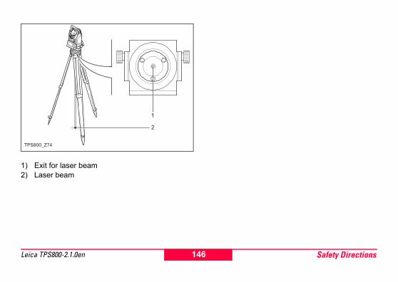
1) Exit for laser beam2) Laser beam
TPS800_Z74
146 Safety DirectionsLeica TPS800-2.1.0en

Electromagnetic Compatibility EMCThe term Electromagnetic Compatability is taken to mean the capability of the product to function smoothly in an environment where electromagnetic radiation and electrostatic discharges are present, and without causing electromagnetic disturbances to other equipment.
� WarningElectromagnetic radiation can cause distur-
bances in other equipment.
Although the product meets the strict regulations and standards which are in force in this respect, Leica Geosystems cannot completely exclude the possibility that other equipment may be disturbed.
� CautionThere is a risk that disturbances may be
caused in other equipment if the product is used in conjunction with accessories from other manufac-
turers, for example field computers, personal computers, two-way radios, non-standard cables or external batteries.Precautions:Use only the equipment and accessories recom-mended by Leica Geosystems. When combined with the product, they meet the strict requirements stipulated by the guidelines and standards. When using computers and two-way radios, pay attention to the information about electromagnetic compatibi-lity provided by the manufacturer.
� CautionDisturbances caused by electromagnetic
radiation can result in erroneous measurements.Although the product meets the strict regulations and standards which are in force in this respect, Leica Geosystems cannot completely exclude the possibility that the product may be disturbed by very intense electromagnetic radiation, for example, near radio transmitters, two-way radios or diesel genera-tors.
147Safety Directions Leica TPS800-2.1.0en

Precautions:Check the plausibility of results obtained under these conditions.
� WarningIf the product is operated with connecting
cables attached at only one of their two ends, for example external supply cables, interface cables, the permitted level of electromagnetic radiation may be exceeded and the correct functioning of other products may be impaired.Precautions:While the product is in use, connecting cables, for example product to external battery, product to computer, must be connected at both ends.
FCC Statement, Applicable in U.S.
� WarningThis equipment has been tested and found to
comply with the limits for a Class B digital device, pursuant to part 15 of the FCC rules.These limits are designed to provide reasonable protection against harmful interference in a residen-tial installation.This equipment generates, uses and can radiate radio frequency energy and, if not installed and used in accordance with the instructions, may cause harmful interference to radio communication.However, there is no guarantee that interference will not occur in a particular installation.
If this equipment does cause harmful interference to radio or television reception, which can be deter-mined by turning the equipment off and on, the user is encouraged to try to correct the interference by one or more of the following measures:• Reorient or relocate the receiving antenna.
148 Safety DirectionsLeica TPS800-2.1.0en

• Increase the separation between the equipment and receiver.
• Connect the equipment into an outlet on a circuit different from that to which the receiver is connected.
• Consult the dealer or an experienced radio/TV technician for help.
� Warning Changes or modifications not expressly
approved by Leica Geosystems for compliance could void the user's authority to operate the equip-ment.Labelling:
TPS800_Z75
........ ..............
. . . . . . . .
. . . . . . . . . . . . . . . . . . . . .
. . . . . . . . . . . . . . . . . . . . .
. . . . . . . . . . . . . . . . .
. . . . . . . . . . . . . . . . . . . . . .
. . . . . . . . . . . . . . . . . . .
This device complies with part 15 of the FCC Rules. Operation is subject to the following two conditions: (1) This device may not cause harm-ful interference, and (2) this device must accept any interference received, including inter-ference that may cause undesired operation.
149Safety Directions Leica TPS800-2.1.0en

Technical DataTelescope• Transit fully• Magnification:............................................. 30x• Image: ................................................... upright• Free Objective aperture: ....................... 40 mm• Focusing: ..................... 1.7 m (5.6 ft) to infinity• Field of view: ..............................1°30' (1.7gon)• Field of view at 100m.............................. 2.6 mAngle measurement• absolute, continuous, • Updates each 0.3 seconds• Units selectable
360° sexagesimal, 400gon, 360° decimal, 6400 mil, V%, ±V
• Accuracy standard deviation Hz, V(acc. to ISO 17123-3)TC(R)802 ................................... 2" (0.6 mgon)TC(R)803 ................................... 3" (1.0 mgon)TC(R)805 ................................... 5" (1.5 mgon)
• Display resolutiongon........................................................ 0.0001360d...................................................... 0.0001360s ..............................................................1"mil ............................................................. 0.01
Level sensitivity• Circular level: ...................................... 6'/2 mmCompensator:• 2-axis-oil compensator• Setting range ............................. ±4' (0.07 gon)• Setting accuracy ..............................................
TC(R)802 ................................ 0.5" (0.2 mgon)TC(R)803 ................................... 1" (0.3 mgon)TC(R)805 ................................ 1.5" (0.5 mgon)
150 Technical DataLeica TPS800-2.1.0en

Laser plummet• Location: ..............in vertical axis of instrument• Type: ...........................visible red laser class 2• Carrier wave: ....................................... 635 nm• Accuracy: ..................................Deviation from
.............................................plumbline 1.5 mm
............................................ (2 sigma) at 1.5 m
............................................. instrument height• Diameter of laser point:............ 2.5 mm / 1.5 mKeyboard:• Tilt angle: ....................................................70°• optional 2nd keyboardDisplay:• Backlit• Heatable................................... (Temp. < -5°C)• LCD:........................................ 280 x 160 Pixel• 8 lines with 31 characters eachType of tribrach:• Tribrach removable GDF111
Thread diam.:.............................................5/8" .........................................(DIN 18720 / BS 84)
Dimensions:• Instrument: .......................................................
Height (including tribrach and carrying handle):- with tribrach GDF111.................................................................................... 360 mm ± 5 mmWidth:.................................................. 207 mmLength: ................................................ 150 mm
• Case: ................................... 468x254x355mm............................................................ (LxBxH)
Weight: (including battery and tribrach)• with tribrach GDF111............................. 5,2 kgTilting axis height:• without tribrach ................................... 196 mm• with tribrach GDF111............. 240 mm ± 5 mmPower supply:• Battery GEB111: ......................................NiMh
Voltage:........................................................6VCapacity: ..........................................2100 mAh
• Battery GEB121: ......................................NiMhVoltage:........................................................6VCapacity: ..........................................4200 mAh
151Technical Data Leica TPS800-2.1.0en

• External supply(via serial interface)............................. If an external cable is used,........................ then the voltage range must lie ..................................between 11.5V and 14V.
No. of measurements (angle + distance):• GEB111: ..................................... approx. 4000• GEB121: ..................................... approx. 9000Temperature range:
Automatic corrections:• Line-of-sight error ......................................Yes• Vertical-index error.....................................Yes• Earth curvature ..........................................Yes• Refraction ..................................................Yes• Tilt correction .............................................Yes
Recording:• RS232 interface .........................................Yes• Internal Memory ........................................Yes
Total capacity....................................... 576 KB................................... ≈ 10000 data blocks or............................................ ≈ 16000 fixpoints
Type Operating temperature
Storage temperature
TPS800 -20°C to +50°C / -4°F to +122°F
-40°C to +70°C / -40°F to +158°F
Battery internal -20°C to +50°C / -4°F to +131°F
-40°C to +55°C / -40°F to +131°F
152 Technical DataLeica TPS800-2.1.0en

Distance measurement (IR: Reflector mode):
* Beam interruptions, severe heat shimmer and moving objects within the beam path can result in deviations of the specified accuracy.
1) Strong haze, visibility 5km; or strong sunlight, severe heat shimmer
2) Light haze, visibility about 20km; or moderate sunlight, slight heat shimmer
3) Overcast, no haze, visibility about 40km; no heat shimmer
Principle: Phase measurementType: Coaxial, infrared laser
Class 1Carrier wave: 780 nmMeasuring system: Special frequency
system basis 100 MHz 1.5 m
Principle: Phase measurementType: Coaxial, visible red
laser Class 1Carrier wave: 660 nmMeasuring system: System analyser basis
100 MHz - 150 MHz
EDM measuring program
Accuracy*(Standard deviation acc. to ISO 17123-4)
Time per measure-
mentIR_Fine 2 mm + 2 ppm <1 sec.
IR_Fast 5 mm + 2 ppm <0.5 sec.
Tracking 5 mm + 2 ppm <0.3 sec.
IR Tape 5 mm + 2 ppm <0.5 sec
Range: (normal and rapid measurement)
Standard prism
3 prisms (GPH3)
360° reflector
Tape 60mm x 60mm
Mini prism
360° Mini prism
1 1800 m (6000 ft)
2300 m(7500 ft)
800 m (2600 ft)
150 m (500 ft)
450 m (1500 ft)
450 m (1500 ft)
2 3000 m (10000 ft)
4500 m(14700 ft)
1500 m (5000 ft)
250 m (800 ft)
800 m (2600 ft)
800 m (2600 ft)
3 3500 m (12000 ft)
5400 m(17700 ft)
2000 m (7000 ft)
250 m (800 ft)
1000 m (3500 ft)
1000 m (3500 ft)
EDM measuring program
Accuracy*(Standard deviation acc. to ISO 17123-4)
Time per measure-
ment
153Technical Data Leica TPS800-2.1.0en

Distance measurement (RL: Reflectorless mode) Distance measurement (with reflector)• Range of measurement: .......... from 1000m up• Display unambiguous: ....................... to 12 km
1) Strong haze, visibility 5km; or strong sunlight, severe heat shimmer
2) Light haze, visibility about 20km; or moderate sunlight, slight heat shimmer
3) Overcast, no haze, visibility about 40km; no heat shimmer
Measuring system R100:
Special frequency system basis 100 MHz 1.5 m
Measuring system R300:
System analyser basis 100 MHz - 150 MHz
Type: Coaxial, visible red laser Class 3R
Carrier wave: 670 nm
Measuring system:
System analyser basis 100 MHz - 150 MHz
Type: Coaxial, visible red laser Class 3R
Carrier wave: 660 nm
Ultra&Power: Range (with reflector)Atmospheric conditions
Standard-prism
Reflector tape60 x 60
1 2200 m (7200 ft) 600 m (2000 ft)2 7500 m (24600 ft) 1000 m (3300 ft)3 > 10000 m (33000 ft) 1300 m (4200 ft)
154 Technical DataLeica TPS800-2.1.0en

Distance measurement (without reflector)• Range of measurement:
Power....................................... 1.5 m to 300 m...................................(to target plate 710 333)Ultra ...................................... 1.5 m to > 500 m...................................(to target plate 710 333)
• Display unambiguous:........................ to 760 m• Prism constant (additive constant):.+ 34.4 mm
* Kodak Grey Card used with exposure meter for reflected light
4) Object in strong sunlight, severe heat shimmer5) Object in shade, or sky overcast6) Day, night and twilight
** Beam interruptions, severe heat shimmer and moving objects within the beam path can result in deviations of the specefied accuracy.
Power: Range (without reflector)Atmospheric conditions
No reflector (white target)*
No reflector (grey, albedo 0.25)
4 140 m (460 ft) 70 m (230 ft)5 170 m (560 ft) 100 m (330 ft)6 >170 m (560 ft) >100 m (>330 ft)
Ultra: Range (without reflector)Atmospheric conditions
No reflector (white target)*
No reflector (grey, albedo 0.25)
4 300 m (990 ft) 200 m (660 ft)5 500 m (1640 ft) 300 m (990 ft)6 >500 m (1640 ft) >300 m (>990 ft)
EDM measuring program
Accuracy**(Standard deviation acc. to ISO 17123-4)
Time per measure-ment
Short 3 mm + 2 ppm 3.0 sec. +1.0 sec./10m > 30m
Prism 5 mm + 2 ppm 2.5 sec.
Tracking 5 mm + 2 ppm 1.0 sec. +0.3 sec./10m > 30m
155Technical Data Leica TPS800-2.1.0en

Atmospheric correctionThe distance displayed is correct only if the scale correction in ppm (mm/km) which has been entered corresponds to the atmospheric conditions prevai-ling at the time of the measurement.
The atmospheric correction takes air pressure and air temperature into account.For utmost precision in distance measurements, atmospheric correction must be determined with 1 ppm accuracy, air temperature to 1°C and air pres-sure to 3mb accuracy.
156 Technical DataLeica TPS800-2.1.0en

Atmospheric correction in ppm with °C, mb, H (metres) at 60% relative humidity
TPS800_Z76
-40-3
5-30-2
5-20-1
5-10
-5
0
5101
5202
5303
5
404
5505
5
606
5
707
5
808
5
90
95100105110115120125130135140
50°C50°C
40°C40°C
30°C30°C
20°C20°C
10°C10°C
0°C 0°C
-10°C-10°C
-20°C-20°C
550 mb
5000 m 4500
600 650 700 750 800 850 900 950 1000 1050 mb
550 mb 600 650 700 750 800 850 900 950 1000 1050 mb
4000 3500 3000 2500 2000 1500 1000 500 0 m
157Technical Data Leica TPS800-2.1.0en

Atmospheric correction in ppm with °F, inch Hg, H (feet) at 60% relative humidity
TPS800_Z77
130°F
120°F
110°F
100°F
90°F
80°F
70°F
60°F
50°F
40°F
30°F
20°F
10°F
0°F
-10°F
-20°F
130°F
120°F
110°F
100°F
90°F
80°F
70°F
60°F
50°F
40°F
30°F
20°F
10°F
0°F
-10°F
-20°F
16
[ ft ]
17 18 19 20 21 22 23 24 25 26 27 28 29 30 31 32 inch Hg
16 17 18 19 20 21 22 23 24 25 26 27 28 29 30 31 32 inch Hg
16000
15000
14000
13000
12000
11000
10000
9000
8000
7000
6000
5000
4000
3000
2000
1000
o ft
-15
-20
-25
-30
-35
-40
-45
-50
-55
-10-5
051
0152
0253
0354
0455
0556
0657
0758
0859
095100105110115120125130135140145
158 Technical DataLeica TPS800-2.1.0en

Reduction formulae
Height measurement1) Mean sea level2) Instrument3) Reflector
The instrument calculates slope distance, horizontal distance and height difference in accordance with the following formula. Earth curvature and mean refraction coefficient (k = 0.13) are taken into account automatically. The calculated horizontal distance relates to the station height, not to the reflector height.
= displayed slope distance [m]D0 = uncorrected distance [m]ppm = scale correction [mm/km]mm = prism constant [mm]
= horizontal distance [m]= height difference [m]
TPS800_Z78
= D0 · (1 + ppm · 10-6) + mm
= Y - A · X · V
= X + B · Y2
159Technical Data Leica TPS800-2.1.0en

Y = · |sin ζ |X = · cos ζζ = vertical-circle reading
A = = 1.47 · 10-7 [m-1]
B = = 6.83 · 10-8 [m-1]
k = 0.13R = 6.37 · 106 m
160 Technical DataLeica TPS800-2.1.0en

Index2D-Road ....................................................... 53, 83
AAbbreviations ...................................................... 12Additional characters .......................................... 36Adverse uses .................................................... 126Alphanumeric keys ............................................. 18Angle measurement ......................................... 150Angle Unit ......................................................... 100Application default settings ................................. 47Applications ........................................................ 53Area .................................................................... 77ATMOS ............................................................. 104Atmospheric correction ..................................... 156Automatic corrections ....................................... 152Auto-OFF ............................................................ 99Azimuth .............................................................. 76
BBase Line ..................................................... 63, 64Battery .............................................................. 121Battery capacity .................................................. 24
Baudrate ........................................................... 119Beep ................................................................... 98Brg ...................................................................... 76
CCare and Transport .......................................... 123Cartesian Stake out ............................................ 56Centring .............................................................. 30Character set ...................................................... 36Check & Adjust ................................................. 110Check Tie ........................................................... 41Circular level .................................................... 114Cleaning and Drying ......................................... 125Code Record .................................................... 100Codelist ............................................................ 107Codelist Manager ............................................... 16COGO .......................................................... 53, 87Collimation axis .................................................. 12Communication parameters ............................. 119Compensator .............................................. 24, 150Computation procedure ...................................... 58Construction ....................................................... 53
161Index Leica TPS800-2.1.0en
Construction application ..................................... 81Contrast .............................................................. 96Coordinate Editor ............................................... 16
DData Exchange Manager .................................... 16Data Output ........................................................ 98Data Transfer ................................................... 120Databits ............................................................ 119Date .................................................................. 121Delete Last Record ............................................. 41Dimensions ....................................................... 151Display .............................................................. 151Display Heater .................................................... 98Distance measurement .............. 20, 153, 154, 155Distance Unit .................................................... 100
EEdit mode ........................................................... 35EDM Mode ....................................................... 101EDM Settings ................................................... 101EDM type ............................................................ 24EGL .................................................................. 103Electromagnetic Compatibility EMC ................. 147Electronic Guide Light EGL .............................. 142
Electronic level ............................................. 32, 33Endmark ........................................................... 119Erasing characters ............................................. 35ESC .................................................................... 19Extending / editing code ..................................... 93
FFace I Definition ............................................... 100FCC Statement ................................................ 148File Management ............................................. 106Fixed keys .......................................................... 19Fixpoints ........................................................... 107FNC .............................................................. 19, 40Free Station ........................................................ 57Free-Coding ....................................................... 40Function keys ..................................................... 18
GGSI 8/16 ............................................................. 98GSI output format ............................................... 98GSI output mask ................................................ 98GSI-coding ......................................................... 92GSI-ID’s ............................................................ 120Guide Light ....................................................... 103
162 IndexLeica TPS800-2.1.0en

HHazards of use ................................................. 130Height transfer .................................................... 44Hidden Point ....................................................... 45Horizontal circle .................................................. 12Horizontal direction ............................................. 12Hz Collimation .................................................... 99Hz Incrementation .............................................. 98
IInitialize Memory .............................................. 108Input mode - method 1 ....................................... 35Inserting / Replacing Battery .............................. 27Inserting characters ............................................ 35Instr.Temp. ....................................................... 121Instrument Protection ....................................... 122Interface ........................................................... 119Interface plug connections ............................... 119Intersection
Bearing - Bearing ......................................... 88Bearing - Distance ....................................... 89By Points ...................................................... 90Distance - Distance ...................................... 89
Intersections ....................................................... 88
Inverse ............................................................... 87IR ........................................................................ 40IR/ RL Toggle ..................................................... 40IR-Fast ............................................................. 101IR-Fine ............................................................. 101IR-Tape ............................................................ 101IR-Track ........................................................... 101
JJob ................................................................... 106JPMINI ............................................................. 102
KKeyboard .......................................................... 151Keypad ............................................................... 18Known Point ....................................................... 48
LLabelling ........................................... 136, 145, 149Laser Classification
Integrated Distancer, Visible Laser .... 134, 137Laser classification ........................................... 134Laser intensity .................................................... 34Laser plummet ................................. 115, 144, 151Laser Pointer .................................................... 103
163Index Leica TPS800-2.1.0en

Laserpointer ....................................................... 40Leica Geo Office Tools ................................. 15, 95Level ................................................................... 33Level sensitivity ................................................ 150Level/Plummet .................................................... 40Light On /Off ....................................................... 40Limits of use ..................................................... 127Line of sight ........................................................ 12Line-of-sight error ....................................... 13, 110
MMain Settings ...................................................... 43Manual
Validity of user manual ................................... 4Manual code input .............................................. 93Mask 1/2 ............................................................. 98Measurements ............................................ 57, 107Measuring ........................................................... 39Measuring facilities ............................................. 58Memory ............................................................ 108MENU ........................................................... 19, 25Menu tree ........................................................... 25Min. Reading ...................................................... 99
NNavigation keys .................................................. 18No. of measurements ....................................... 152
OOffset
Distance - Offset .......................................... 90Extention ...................................................... 91Set Point by ... ............................................. 91
Orientation .......................................................... 49Orthogonal Setout .............................................. 68Orthogonal Stake out ......................................... 56
PPAGE ................................................................. 19Parity ................................................................ 119Permitted uses ................................................. 126PIN ............................................................. 41, 122Plumb line .......................................................... 13Pointsearch ........................................................ 37Polar Stake out ................................................... 55Polygonal Method .............................................. 75Positioning .......................................................... 34Power supply .................................................... 151PPM ................................................................. 104
164 IndexLeica TPS800-2.1.0en

Pressure ........................................................... 100Prism Constant ................................................. 103Prism type ........................................................ 102Programs ............................................................ 47PUK code ......................................................... 122
QQuick Code ......................................................... 94
RRadial Method .................................................... 75Range ............................................... 153, 154, 155Recording ......................................................... 152Recording code block ......................................... 93Reduction formulae .......................................... 159Reference Arc .................................................... 70Reference height ................................................ 63Reference Line ................................................... 63Reference Line/Arc ............................................. 63Reflective targets .............................................. 102Reflectorless EDM ............................................ 116Refraction correction ........................................ 105Remote Height ................................................... 80Responsibilities ................................................ 128Reticle ................................................................ 13
Reticle Illumin. .................................................... 98RL ....................................................................... 40RL-Prism .......................................................... 102RL-Short ........................................................... 102RL-Track .......................................................... 102Rod Length ......................................................... 45RS232 ................................................................ 98
SSafety Directions .............................................. 126SCALE ............................................................. 104Sector Beep ....................................................... 97Set manually ...................................................... 48Setting job .......................................................... 47Setting Station .................................................... 48Settings .............................................................. 96Signal ............................................................... 105Signs .................................................................. 36Softkeys ............................................................. 23Software Upload ................................................. 16Stake out ............................................................ 55Stake Out Angle ................................................. 74Stake Out Arc ..................................................... 72Stake Out Chord ................................................ 73Stake Out Point .................................................. 71
165Index Leica TPS800-2.1.0en

Standard prism ................................................. 102Standing axis ...................................................... 12Standing axis inclination ..................................... 13Start programs .................................................... 47Start-up sequence ............................................ 109Statistics ........................................................... 108Stopbits ............................................................ 119Storage ............................................................. 124Surveying ........................................................... 54Symbols .............................................................. 24System Info ...................................................... 121
TTarget Offset ...................................................... 42Technical Data ................................................. 150Technical terms .................................................. 12Telescope ......................................................... 150Temperature ..................................................... 100Temperature range ........................................... 152Tie Distance ....................................................... 75Tilt Correction ..................................................... 96Tilting axis .......................................................... 12Tilting axis height .............................................. 151Time ................................................................. 121Tracking .............................................................. 42
Transport .......................................................... 123Traverse ............................................................. 88Tribrach .................................................... 115, 151Trigger key ................................................... 19, 96Tripod ................................................... 29, 32, 114
UUnits ................................................................... 40USER ................................................................. 19USER Key .......................................................... 96
VVertical angle ..................................................... 12Vertical circle ...................................................... 12V-Index ....................................................... 13, 110Volume ......................................................... 53, 77V-Setting ............................................................ 96
WWeight .............................................................. 151Wildcard search ................................................. 38
ZZenith ................................................................. 13Zenith angle ....................................................... 12
166 IndexLeica TPS800-2.1.0en

167Index Leica TPS800-2.1.0en

Total Quality Management: Our commitment to total customer satisfaction.
Leica Geosystems AG, Heerbrugg, Switzerland, has been certified as being equipped with a quality system which meets the International Standards of Quality Management and Quality Systems (ISO standard 9001) and Environmental Management Systems (ISO standard 14001).
Ask your local Leica dealer for more information about our TQM program
7426
17-2
.1.0
en O
rigin
al t
ext
Prin
ted
in S
witz
erla
nd ©
200
5 Le
ica
Geo
syst
ems
AG, H
eerb
rugg
, Sw
itzer
land
Leica Geosystems AGHeinrich-Wild-StrasseCH-9435 HeerbruggSwitzerlandPhone +41 71 727 31 31www.leica-geosystems.com