Leica TCS SP5 II Instructions -...
34
Hilenski February 2013 http://medicine.emory.edu/MIMCore 1 Leica TCS SP5 II Instructions Leica True Confocal Scanning-Spectral Photometric 5 Microscopy in Medicine (MiM) Core Leica TCS SP5 II Located in WMB 1011: KEY CARD ACCESS ONLY Emory University Department of Medicine
Transcript of Leica TCS SP5 II Instructions -...

Hilenski February 2013 http://medicine.emory.edu/MIMCore
1
Leica TCS SP5 II Instructions Leica True Confocal Scanning-Spectral Photometric 5
Microscopy in Medicine (MiM) Core
Leica TCS SP5 II Located in WMB 1011: KEY CARD ACCESS ONLY
Emory University
Department of Medicine

Hilenski February 2013 http://medicine.emory.edu/MIMCore
2
OPERATION OF THE LEICA TCS SP5 II
YOU MUST SIGN UP TO USE THE LEICA SYSTEM OR COMPUTER EVERY TIME—NO EXCEPTIONS
YOUR EMORY ID # SHOULD BE GIVEN TO THE MiM CORE STAFF TO ALLOW KEY CARD ACCESS TO WMB 1011
Before attempting to use the microscope:
• you should grow or mount specimens on glass with 1.5 thickness (see MatTek dishes ordering information below). For a discussion on why this is important, see http://www.microscopyu.com/articles/formulas/formulascoverslipcorrection.html.
• you should read information on live cell imaging and issues such as photobleaching. A good place to start is http://microscopyu.com/articles/livecellimaging/index.html.
• you should also know the excitation and emission spectra for your particular fluorochromes so that you can select the proper configurations available in the software. See the charts with this information at http://www.mcb.arizona.edu/ipc/fret/default.htm.
• the Leica TCS SP5 II has four lasers with the following lines for excitation: Lasers
Diode 50 mW with 405 nm emission line "Blue" argon multi-line 65 mW with 458/476/488/514 nm
emission lines "Yellow" diode 20 mW with 561 nm emission line "Red" 10 mW with 633 nm emission line
• Detector Channels TLD brightfield detector One internal detector channel (PMT) Three internal GaAsP detector channels (HyD)
• you should familiarize yourself with the choices of objectives on the microscope and the meanings of the markings on the objectives (e.g., the magnification, the numerical aperture (NA), the coverslip thickness requirements). To learn these markings and their meaning, see http://olympusmicro.com/primer/anatomy/specifications.html.
Objective/Leica # Magnification Air/Oil/Glycerol
Numerical Aperture
Working Distance
HC PL APO CS 11506285 10x air 0.40 NA 2.2 mm WD HC PL APO CS 15506513 20x air 0.70 NA 0.59 mm WD HCX PL APO 15506331 40x oil 1.3 NA 0.22 mm WD HCX PL APO CS 11506188 63x oil 1.4-0.6 NA 0.10 mm WD HCX PL APO CS 11506194 63x GLYCEROL 1.3 NA 0.28 mm WD
The revised edition of HANDBOOK OF BIOLOGICAL CONFOCAL MICROSCOPY edited by
James B. Pawley is available for reading on the theory of confocal imaging systems (a newer 2nd edition is available from the Emory Woodruff Library); also available is CONFOCAL MICROSCOPY FOR BIOLOGISTS by Alan Hibbs.
A good introduction to light microscopy is OPTIMIZING LIGHT MICROSCOPY FOR BIOLOGICAL AND CLINICAL LABORATORIES by Barbara Foster available on book shelf (Hilenski personal copy, so please return).

Hilenski February 2013 http://medicine.emory.edu/MIMCore
3
A good introduction to image acquisition is North, A.J. 2006. Seeing is believing? A beginners’ guide to practical pitfalls in image acquisition. J Cell Biol 172:9-18. Copies are also available in the MiM Core. What users should consider purchasing: Glass Coverslips (# 1.5) Blank CDs and DVDs
Glass Bottom 35 mm Dishes (MatTek Corporation, 200 Homer Ave., Ashland, MA 01721; Phone 508-881-6771; FAX 508-879-1532) (used for viewing live cells/living tissue in a fluid). Order coverglass thickness 1.5. Chambered coverglasses (available from Applied Scientific at 650-244-9851 or http://www.appliedsci.com for part #’s AS-4851 one-chamber; AS-4852 two- chambers; AS-4854 four-chambers; AS-4858 eight-chambers) (used for viewing live cells) IMPORTANT NOTE: Please read about Digital Image Manipulation from Nature (Guide for Digital Images http://www.nature.com/authors/policies/image.html), Journal of Cell Biology http://jcb.rupress.org/site/misc/ifora.xhtml, and the Doug Cromey imaging facility at http://swehsc.pharmacy.arizona.edu/exppath/resources/pdf/Digital_Imaging_Ethics.pdf on the on the acquisition, storage and image processing of digital images taken on the Leica TCS SP5 II system. We advise you to save your original digital images exactly as they were acquired and to record your instrument settings.
BEFORE USING THE SYSTEM, YOU MUST CONTACT:
LU HILENSKI (WMB 329, 7-8116, [email protected]) for TRAINING
You can download a free version of the Leica LAS AF software at the following website: ftp://ftp.llt.de/softlib/LAS_AF_Lite/ (file "setup.exe" from the Leica FTP server). You can also use the Leica LAS AF full software on the WMB 306 workstation computer. Please check out the dongle from WMB 303. Other excellent websites for understanding microscopy are listed below:
http://micro.magnet.fsu.edu/primer/index.html
http://microscopyu.com/
http://olympusmicro.com/

Hilenski February 2013 http://medicine.emory.edu/MIMCore
4
The following instructions are taken from the Leica TCS SP5II Operating Manual (http://taltos.stanford.edu/docs/QUICK-START%20LASAF%20SP5.pdf) and from other microscopy
facilities, including the following: University of Maryland:
http://www.cbmg.umd.edu/files/cbmg/corelab/SP5X%20Quick%20Start%20Guide.pdf
McMaster Biophotonics Facility: http://www.macbiophotonics.ca/PDF/SP5System.pdf LSU Health Sciences: http://www.sh.lsuhsc.edu/oor/rcf/Microscopy/Leica%20Confocal/QuickStartGuide/Leica%20Quick%20Start%20Guide.pdf

Hilenski February 2013 http://medicine.emory.edu/MIMCore
5
POWER UP Procedure for Leica TCS SP5 II
Record Steps Below on the Leica LOG SHEET 1. Starting up the Cube and Box environmental chamber and The Brick gas mixer: NOTE: The Cube ALWAYS STAYS ON so that the temperature inside the Box is held at 37° C. NOTE: The house compressed air TO THE VIBRATION TABLE ALWAYS STAYS ON (on the wall behind the Leica). Make sure the deionized water level in the humidifier column inside the environmental Box is filled to the black mark. If necessary, add deionized water. Turn on the valves (1) on the house compressed air (mounted on the wall to the left of the CO2 tank) and (2) on the CO2 tank. If these pressures are not correct, contact Lu Hilenski, WMB 329, 404-727-8116.
Air pressure should read between 0.8-1.2 bars or 11.6-17.4 psi
CO2 pressure should read between 5-7 bars or 11.6-17.4 psi

Hilenski February 2013 http://medicine.emory.edu/MIMCore
6
Turn on the Brick. You should see bubbles in the humidifier column inside the environmental Box.
Start the Hardware 1. Turn on the Leica mercury lamp power supply. The green power light and the yellow shutter light will come on. Be sure to record in the log sheet the number of hours displayed. Once turned on, the lamp should remain on for a minimum of 30 minutes. 2-5. Turn on the PC Microscope switch (#2), the Scanner Power switch (#3) and the Laser Power switch (#4). Then turn the key to the Laser Emission switch (#5) clockwise to the On-1 position.
Hilenski February 2013 http://medicine.emory.edu/MIMCore
7
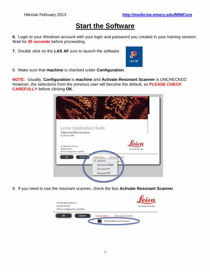
Start the Software 6. Login to your Windows account with your login and password you created in your training session. Wait for 45 seconds before proceeding. 7. Double click on the LAS AF icon to launch the software. 8. Make sure that machine is checked under Configuration. NOTE: Usually, Configuration is machine and Activate Resonant Scanner is UNCHECKED. However, the selections from the previous user will become the default, so PLEASE CHECK CAREFULLY before clicking OK. 9. If you need to use the resonant scanner, check the box Activate Resonant Scanner.

Hilenski February 2013 http://medicine.emory.edu/MIMCore
8
10. IMPORTANT: Read below BEFORE proceeding. When the Microscope Stand windows appears, select No unless you plan to use the Tile or Mark and Find functions for the motorized stage. NOTE: If you need to initialize the stage, you must first tilt the transmitted light arm (condenser arm) back from the stage, because the motorized stage might possibly hit the condenser during initialization. Then click Yes.
If YES, then tilt condenser arm UP. 11. Click on the Configuration tab and select Laser. 12. In the Laser Switch box, activate only the lasers you need by checking the boxes. If you are using the Argon laser, type in 25% in the box. Click ENTER on the keyboard.

Hilenski February 2013 http://medicine.emory.edu/MIMCore
9
Find your Sample: Choose an Objective Lens 1. Click on Acquire>Acquisition. Click on Objective and choose an objective lens from the drop down menu. 10x air 0.40 NA 20x air 0.70 NA 40x oil 1.3 NA 63x oil 1.4-0.6 NA 63x GLYCEROL 1.3 NA 2. Place the appropriate immersion media (EXCEPT for the air lenses 10x and 20x) on the objective lens. Place your sample on the microscope stage. BE VERY GENTLE--the stage is very delicate. Position the sample over the lens using the stage controller on the SmartMove and focus using the Z axis wheels (either Fine or Course settings). 3. After you have focused the sample, set the upper focus stop by pressing both SET + Z on the right front of the microscope until the Z position on the LCD panel on the front of the microscope reads 0 μm. (NOTE: If the upper focus is not set, the display will read --.--mm). Press together
Fine
Course

Hilenski February 2013 http://medicine.emory.edu/MIMCore
10
Find your Sample: Brightfield 1. Select the CHG TL button on the left side of the microscope. 2. The LCD screen on the microscope front should display TLD_BF. You can switch between BF and DIC by pressing the CHG TL button.
Z-position
Imaging mode/shutter position
Lens and magnification
Illumination intensity and aperture setting
Focus mode

Hilenski February 2013 http://medicine.emory.edu/MIMCore
11
3. If you are planning to use DIC (transmitted image), you need to set up Köhler illumination by the following steps: 1. Focus on your sample. 2. Close the field iris diaphragm.
3. Focus the condenser using the focusing knob until you see a small circle of light with clear, sharp edges. 4. Center the circle of light with the alignment pins. 5. Open the field diaphragm just beyond the field of view.

Hilenski February 2013 http://medicine.emory.edu/MIMCore
12
I3: Green LP N2.1: Red A: UV
Find your Sample: Fluorescence 1. Choose one of the filter sets on the front of the microscope and press the shutter button. 2. You can adjust the intensity of the mercury lamp with the INT button and the field diaphragm with the FD button on the left side of the microscope.

Hilenski February 2013 http://medicine.emory.edu/MIMCore
13
Image Acquisition 1. Click on Acquire. 2. The default settings are as follows: Acquisition Mode: xyz Image format: 512x512 pixels
NOTE: Image size and pixel size are automatically calculated and displayed.
Speed: 400 Hz with a zoom factor of 1. Pinhole size: 1 Airy unit
NOTE: To change the pinhole size, check the box next to the Pinhole and adjust.
Bit depth: 8 You can expand any menu by clicking on the arrows at the upper right of the menu window.
Hilenski February 2013 http://medicine.emory.edu/MIMCore
14
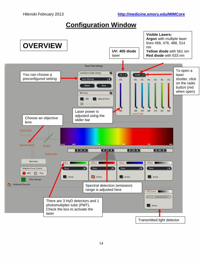
Configuration Window
UV: 405 diode laser
You can choose a preconfigured setting
Visible Lasers: Argon with multiple laser lines 458, 476, 488, 514 nm Yellow diode with 561 nm Red diode with 633 nm
Transmitted light detector
Laser power is adjusted using the slider bar
There are 3 HyD detectors and 1 photomultiplier tube (PMT). Check the box to activate the laser
Choose an objective lens
Spectral detection (emission) range is adjusted here
To open a laser shutter, click on the radio button (red when open)
OVERVIEW

Hilenski February 2013 http://medicine.emory.edu/MIMCore
15
Beam Path Settings 1. To activate a detector (HyD or PMT), click on the Active button and choose the color for your fluorophore emission.
Click on Active button.
Choose the color for the fluorophore emission by clicking on the box next to the laser, then choosing an LUT in the LUT selection window.

Hilenski February 2013 http://medicine.emory.edu/MIMCore
16
2. Choose the laser power by either (1) moving the digital slider arrow up or down OR (2) by clicking on the laser power % and typing in the number, then OK.
OR
3. Choose the spectral range of the emission fluorophore by clicking on the arrows and dragging them to the left or right OR by double clicking on the slider bar and typing in new minimum/maximum numbers.
NOTE: The spectral range should always be at least 10 nm greater than the excitation laser line. Example: If using the 405 nm laser, then the minimum in the spectral range should be at least 415 nm.

Hilenski February 2013 http://medicine.emory.edu/MIMCore
17
Beam Path Settings Setting up sequential scans: DAPI/FITC/TRITC example 1. Click on Seq in the Acquisition Mode window. 2. In the Sequential Scan window, select the between frames radio button. 3. Set up Scan 1 for DAPI only.
Make sure the UV laser red button is activated.
Load the DAPI emission curve by selecting DAPI from the drop-down menu.
Set the UV laser power with the slider. Start with 3%. REMEMBER: The HyD detectors are very sensitive. Make sure all the other lasers are at 0% power.
Select Substrate dichroic for DAPI.
Click on the Active button below the HyD1 detector.
Set the spectral range and LUT for DAPI as described above. REMEMBER: The minimum in the spectral range should be 10 nm greater than the 405 nm laser line.

Hilenski February 2013 http://medicine.emory.edu/MIMCore
18
4. Make sure that the correct beam path settings are chosen and that the scan parameters are set up correctly by clicking on the Live button to scan your sample. Keep the default values (xyz, 512x512, zoom 1, 400 Hz) initially. 5. Turn the Smart Gain knob on the Smartboard until you can see a signal. FOR HyD DETECTORS, THE SMART OFFSET IS ALWAYS 0.0%, so you can only adjust the gain.

Hilenski February 2013 http://medicine.emory.edu/MIMCore
19
6. To set the proper acquisition parameters, click on the QLUT (Quick Look Up Table) to show pixel intensity values in the image scaled between 0 (black) and 255 (white) in an 8-bit image (256 shades of grey).
Blue= Saturated pixels > 255
Black to Orange to White= Pixels between 1-254
Green= No signal < 0
Adjust Gain
Adjust Offset

Hilenski February 2013 http://medicine.emory.edu/MIMCore
20
7. Adjust the Smart Gain on the Smartboard until there are very few blue pixels in the image. REMEMBER: FOR HyD DETECTORS, THE SMART OFFSET IS ALWAYS 0.0%, so you can only adjust the gain.
Setting up scan 2 (FITC) in the sequential scan
1. In the Sequential Scan window, click on + for scan 2.
Make sure the Visible laser red button is activated.
Load the FITC emission curve by selecting FITC from the drop-down menu.
Set the 488 laser power with the slider. Start with 10%. Make sure all the other lasers are at 0% power.
Select RSP500 dichroic for FITC.
Click on the Active button below the PMT2 detector.
Set the spectral range and LUT for FITC as described above. REMEMBER: The minimum in the spectral range should be 10 nm greater than the 488 nm laser line.

Hilenski February 2013 http://medicine.emory.edu/MIMCore
21
2. Make sure that the correct beam path settings are chosen and that the scan parameters are set up correctly by clicking on the Live button to scan your sample. Keep the default values (xyz, 512x512, zoom 1, 400 Hz) initially. 3. Turn the Smart Gain knob on the Smartboard until you can see a signal.

Hilenski February 2013 http://medicine.emory.edu/MIMCore
22
4. To set the proper acquisition parameters, click on the QLUT (Quick Look Up Table) to show pixel intensity values in the image scaled between 0 (black) and 255 (white) in an 8-bit image (256 shades of grey). 5. Adjust the Smart Gain until there are very few blue pixels in the image. Adjust the Smart Offset until there are few green pixels. NOTE: Gain and Offset can both be set on PMTs.

Hilenski February 2013 http://medicine.emory.edu/MIMCore
23
Setting up scan 3 (TRITC) in the sequential scan 1. In the Sequential Scan window, click on + for scan 3.
Make sure the Visible laser red button is activated.
Load the TRITC emission curve by selecting TRITC from the drop-down menu.
Set the 561 laser power with the slider. Start with 5%. Make sure all the other lasers are at 0% power.
Select TD 488/561/633dichroic for TRITC.
Click on the Active button below the HyD3 detector.
Set the spectral range and LUT for TRITC as described above. REMEMBER: The minimum in the spectral range should be 10 nm greater than the 561 nm laser line.

Hilenski February 2013 http://medicine.emory.edu/MIMCore
24
2. Make sure that the correct beam path settings are chosen and that the scan parameters are set up correctly by clicking on the Live button to scan your sample. Keep the default values (xyz, 512x512, zoom 1, 400 Hz) initially. 3. Turn the Smart Gain knob on the Smartboard until you can see a signal.

Hilenski February 2013 http://medicine.emory.edu/MIMCore
25
4. To set the proper acquisition parameters, click on the QLUT (Quick Look Up Table) to show pixel intensity values in the image scaled between 0 (black) and 255 (white) in an 8-bit image (256 shades of grey). 5. Adjust the Smart Gain on the Smartboard until there are very few blue pixels in the image. REMEMBER: FOR HyD DETECTORS, THE SMART OFFSET IS ALWAYS 0.0%, so you can only adjust the gain.

Hilenski February 2013 http://medicine.emory.edu/MIMCore
26
5. When the adjustments in each detector channel have been made (minimum blue, minimum green pixels in glow scale), use the Z position knob on the Smartboard for final focus adjustment. Then click on the Start button to capture the sequential scans for all channels. In ‘between frames’ mode, each channel will be scanned sequentially.
Click to show LUT pseudocolors.
Click to show merged channel.
Double click on active (outlined) window to show single channel.

Hilenski February 2013 http://medicine.emory.edu/MIMCore
27
Image Optimization 1. In addition to setting the proper dynamic range (few blue, few green pixels in glow scale), there are other adjustments to improve image quality:
Line Average or Frame Average. The sample will be scanned several times (line by line or frame by frame) and the average will be displayed.
Slowing the scan speed. Averaging and slowing the scan speed will slow down the acquisition speed, thus increasing photobleaching. Increasing Format will increase image resolution. Opening the Pinhole (check Pinhole, then set number using slider) allows more light to the
detector, but also allows more out-of-focus light to reach detector. A pinhole of Airy 1 results in the best resolution in the Z axis.

Hilenski February 2013 http://medicine.emory.edu/MIMCore
28
Z-Stack 1. Set the Acquisition Mode to xyz. 2. Click on the Z-Stack window and choose z-Galvo (see window below). 3. Click on the Live button to being scanning. 4. Using the Z-position knob on the Smartboard, move to the top of the sample. 5. Click on the Begin arrowhead (the arrowhead will go from black to brick-colored). 6. Using the Z-position knob on the Smartboard, move to the bottom of the sample. 7. Click on the End arrowhead.

Hilenski February 2013 http://medicine.emory.edu/MIMCore
29
8. Click on Stop. 9. Leave the System optimized to ensure Nyquist sampling. To change the number of steps, click on Nr. of steps or z-step size and enter a new value. 10. Click on Start and the Z-stack will being and end automatically.
3-D Projection
1. To make a MIP (maximum intensity projection) of a Z-stack, click on the Experiments tab and select the Series name. 2. Click on the Process tab. 3. Click on Tools. 4. In the Tools window, click on 3D Projection. 5. Keep the default settings: Viewing Angles 0.0 Options: Maximum Scaling factor 1.00 Threshold 10
6. Click Apply.

Hilenski February 2013 http://medicine.emory.edu/MIMCore
30

Hilenski February 2013 http://medicine.emory.edu/MIMCore
31

Hilenski February 2013 http://medicine.emory.edu/MIMCore
32
3-D Animation 1. To make a 3-D animation of a Z-stack, click on the Experiments tab and select the Series name. 2. Go to Process>Tools. 3. Click under Visualization and 3-D Projection. Click on Create Movie button. 4. Enter the Start Rotation angel (e.g., -45°). Then click Set Start. 5. Enter the End Rotation angle (e.g., +45°). Then click Set End. 6. Enter Options>Maximum. 7. Enter the Number of Frames (the higher the number, the slower the speed of rotation). 8. Click on Apply.

Hilenski February 2013 http://medicine.emory.edu/MIMCore
33
Shutdown Procedure Record Steps Below on the Leica LOG SHEET
1. IF SOMEONE IS SCHEDULED TO USE THE MICROSCOPE AFTER YOU (check the microscope sign-up sheet): SAVE YOUR IMAGES by clicking on Experiments tab>Save All. Exit the LAS AF software. Log out of your Windows account. Copy your images either to a DVD using the Nero software, or copy the images to the I Book
external hard drive. Transfer the images to your lab/personal computer. NOTE: When you have the images safely on your lab/personal computer, DELETE the images from the Leica hard drive.
If using an oil lens, clean the lens with Sparkle and LENS PAPER only. Leave the microscope area CLEAN. DO NOT TURN OFF THE LASERS IF SOMEONE IS SIGNED UP AFTER YOU.
2. IF YOU ARE THE LAST PERSON IN THE DAY TO USE THE SYSTEM: Go to Experiments tab, and SAVE YOUR IMAGES.
Go to the Configuration tab and uncheck all the lasers.
Exit the LAS AF software.
Log out of your Windows account.

Hilenski February 2013 http://medicine.emory.edu/MIMCore
34
Copy your images either to a DVD using the Nero software, or copy the images to the I Book external hard drive. Transfer the images to your lab/personal computer. NOTE: When you have the images safely on your lab/personal computer, DELETE the images from the Leica hard drive.
Go to START, Shutdown.
If using an oil lens, clean the lens with Sparkle and LENS PAPER only.
Leave the microscope area CLEAN.
Turn the laser safety key counter-clockwise to the ‘Off-0’ position.
Wait 2 minutes for the argon laser cooling fan to click off.
Turn off Laser Power (#4), Scanner Power (#3), and then PC Microscope (#2).
Fill in the information in the log book. Be sure to record the Leica mercury lamp hours.
Turn off the Leica mercury lamp.
IF YOU WERE USING THE ENVIRONMENTAL CHAMBER: Turn off the Brick. Turn off the valves (1) on the house compressed air (mounted on the wall to the left of the CO2
tank) and (2) on the CO2 tank.