Leica ScanStation C10/C5 - kb.sccssurvey.co.uk C10/C5, Introduction 2 Introduction To use the...
248
Leica ScanStation C10/C5 System Field Manual Version 5.0 English
Transcript of Leica ScanStation C10/C5 - kb.sccssurvey.co.uk C10/C5, Introduction 2 Introduction To use the...

Leica ScanStation C10/C5System Field Manual
Version 5.0English

2ScanStation C10/C5, Introduction
Introduction
To use the product in a permitted manner, please refer to the detailed safety direc-tions in the User Manual.
Purchase Congratulations on the purchase of a Leica ScanStation C10/C5 instrument.
Productidentification
The type and the serial number of your product are indicated on the type plate.Enter the model and serial number in your manual and always refer to this informa-tion when you need to contact your agency or Leica Geosystems authorised service workshop.
Type: _______________
Serial No.: _______________

ScanStation C10/C5, Introduction 3
Symbols The symbols used in this manual have the following meanings:
Trademarks • Windows is a registered trademark of Microsoft CorporationAll other trademarks are the property of their respective owners.
Validity of this manual
This manual applies to the Leica ScanStation C10 and C5 instruments. Differences for the C5 model are marked and described.
Available docu-mentation
Type Description
Important paragraphs which must be adhered to in practice as they enable the product to be used in a technically correct and efficient manner.
Name Description/Format
Leica ScanStation C10/C5 User Manual
All instructions required in order to operate the product to a basic level are contained in the User Manual. Provides an overview of the product together with technical data and safety directions.

4ScanStation C10/C5, Introduction
Refer to the following resources for all Leica ScanStation C10/C5 documenta-tion and software• Leica ScanStation C10/C5 System CD-ROM• http://www.leica-geosystems.com/downloads• http://www.leica-geosystems.com/en/HDS-Laser-Scanners-SW_5570.htm
Name Description/Format
Leica ScanStation C10/C5 System Field Manual
Describes the general operation of the product in standard use. Intended as a quick reference field guide.
Leica Geosystems External Camera Getting Started
All instructions required in order to setup the external camera kit and to prepare the external camera for operation.
Leica Geosystems HDS Training Manual
Training manual provided in the Leica HDS training course by the local Leica HDS training and support team.
ScanStation C10/C5, Table of Contents 5
Table of ContentsIn this manual Chapter Page
1 Description of the System 10
1.1 Packing / Unpacking 102 Setting Up the Instrument 12
2.1 General Information 122.2 Scanner Setup on Tripod 132.3 Setup Over a Benchmark with the Internal Laser Plummet 152.4 Instrument Height 18
3 Description of the User Interface 20
3.1 Front Side 203.2 Display 213.3 Status Bar 233.4 User Input 30
4 Switching the System On/Off 32
5 Remote Control 34
6 Main Menu 38

6ScanStation C10/C5, Table of Contents
7 Scan 42
7.1 Scan\Scan Begin 427.2 Scan\Setup 45
7.2.1 Scan\Setup\Standard Setup 457.2.2 Scan\Setup\Quick Orientation 467.2.3 Scan\Setup\Set Azimuth 497.2.4 Scan\Setup\Known Backsight 587.2.5 Scan\Setup\Resection 677.2.6 Scan\Setup\Setup Confirmation 79
7.3 Scan\Scan Parameter 887.3.1 Scan\Scan Parameter\Field of View 897.3.2 Scan\Scan Parameter\Resolution 1007.3.3 Scan\Scan Parameter\Image Control\Internal Camera 1057.3.4 Scan\Scan Parameter\Image Control\External Camera 1117.3.5 Scan\Scan Parameter\Filters 1247.3.6 Scan\Scan Parameter\...\Target Definition 127
7.4 Favorite Scan 144

ScanStation C10/C5, Table of Contents 7
8 Manage 146
8.1 Manage\Projects 1488.1.1 Manage\Projects\New Project 1508.1.2 Manage\Projects\Edit Project 1528.1.3 Manage\Projects\Delete Project 1548.1.4 Manage\Projects\Data 1568.1.5 Manage\Projects\Transfer Project 162
8.2 Manage\Targets 1638.2.1 Manage\Targets\New Target 1658.2.2 Manage\Targets\Edit Target 1678.2.3 Manage\Targets\Delete Target 169
8.3 Manage\Control Points 1718.3.1 Manage\Control Points\New Project 1738.3.2 Manage\Control Points\Edit Project 1738.3.3 Manage\Control Points\Delete Project 1738.3.4 Manage\Control Points\Import Control Points 1748.3.5 Manage\Control Points\Data 1798.3.6 Manage\Control Points\Data\New Control Point 1818.3.7 Manage\Control Points\Data\Edit Control Point 1838.3.8 Manage\Control Points\Data\Delete Control Point 1858.3.9 Manage\Control Points\Data\Import Control Points 1868.3.10 Manage\Control Points\Data\Delete All Control Points 186

8ScanStation C10/C5, Table of Contents
9 Status 188
9.1 Status\Battery & Memory 1919.2 Status\System Information 1959.3 Status\Level & Laser Plummet 2009.4 Status\WiFi 207
10 Configuration 212
10.1 Config\Units 21410.2 Config\Time & Date 21610.3 Config\Language 21810.4 Config\Define Favorite 220
11 Tools 226
11.1 Tools\Format 22811.2 Tools\Transfer 23011.3 Tools\License 23711.4 Tools\Display Calibration 241
Index 244

ScanStation C10/C5, Table of Contents 9

10ScanStation C10/C5, Description of the System
1 Description of the System1.1 Packing / Unpacking
Unpacking When in its transport container, the ScanStation C10/C5 can sit in either a face-up or face-down position.
Pack the instrument the same way it is delivered.
To take the instrument out of its container, grasp the handle and the base of the instru-ment, and lift.Use caution due to the weight of the instru-ment (13 kg).
C10_001

ScanStation C10/C5, Description of the System 11
12ScanStation C10/C5, Setting Up the Instrument
2 Setting Up the Instrument2.1 General Information
Use the tripod The instrument should always be set up on its tripod. Using the tripod specified for the scanning system guarantees maximum stability during scanning operations.
Always set up the instrument on its tripod. Do not set up the instrument directly on the ground for scanning operations.
It is always recommended to shield the instrument from direct sunlight and avoid uneven temperatures around the instrument.

ScanStation C10/C5, Setting Up the Instrument 13
2.2 Scanner Setup on Tripod
Setup step-by-step
Shield the instrument from direct sunlight and avoid uneven temperatures around the instrument.
C10_018
1
1
1 3
66
3
34
4
4
25
2

14ScanStation C10/C5, Setting Up the Instrument
1. Extend the tripod legs to allow for a comfortable working posture. Tighten the screws at the bottom of the legs.
2. Place the tribrach on the tripod and secure it with the central fixing screw.3. Set up the tripod so that the tripod plate is as horizontal as possible.4. Push the tripod legs firmly into the ground.5. Place the instrument on the tribrach and secure it with the tribrach’s locking
knob.6. Level up the instrument using the instrument’s circular level. Turn two of the foot
screws together in opposite directions. The index finger of your right hand indi-cates the direction in which the bubble should move. Now use the third foot screw to centre the bubble.
The instrument must be levelled before it is switched ON. If not levelled using the tribrach’s or the instrument’s circular level, it may not power up properly or scanning accuracy may not be achieved.

ScanStation C10/C5, Setting Up the Instrument 15
2.3 Setup Over a Benchmark with the Internal Laser Plummet
Description This topic describes an instrument setup over a marked ground point using the laser plummet. Geo-referencing of the Leica ScanStation C10/C5 is established by setting up over a known or assumed control point, with optional reference target measure-ment to set the azimuth direction, and establishing a local or global coordinate system.The Leica ScanStation C10/C5 allows you to traverse, resect or free-station. Known azimuth or known backsight measurements can be observed.
It is always possible to set up the instrument without the need for a marked ground point.
The data scanned with Leica ScanStation C10/C5 is corrected by an internal dual-axis compensator*, when the dual-axis compensator is enabled (via onboard control or Cyclone).
* Optional for C5
• The laser plummet described in this topic is built into the vertical axis of the instrument. It projects a red spot onto the ground, making it much easier to centre the instrument.
• The laser plummet cannot be used in conjunction with a tribrach equipped with an optical plummet.

16ScanStation C10/C5, Setting Up the Instrument
Setup step-by-step
1. Extend the tripod legs to allow for a comfortable working posture (a). Position the tripod approximately over the marked ground point, centring it as well as possible (b).
2. Place the tribrach on the tripod (c) and secure it with the central fixing screw (d).
Shield the instrument from direct sunlight and avoid uneven temperatures around the instrument.
C10_019
a
ab
a jj
j
c
e
d
i
h
k
fg

ScanStation C10/C5, Setting Up the Instrument 17
3. Place the instrument on the tribrach (e) and secure it with the tribrach’s locking knob.
4. Turn on the instrument by pressing the ON/OFF button (f). Go to Status, Level and Laser Plummet, Plummet and activate the laser plummet (g).
5. Move the tripod legs (a) and use the tribrach footscrews (h) to centre the plummet (i) over the ground point.
6. Adjust the tripod legs (j) to level the circular level (k).7. By using the electronic level (Status, Level and Laser plummet, Level) turn the
tribrach footscrews (h) to precisely level the instrument.8. Centre the instrument precisely over the ground point (i) by shifting the tribrach
on the tripod plate.9. Repeat steps 7. and 8. until the required accuracy is achieved.

18ScanStation C10/C5, Setting Up the Instrument
2.4 Instrument Height
Measure instrument height
To get an accurate height measurement use the GHM008 instrument height meter in conjunction with the GHT196 distance holder which are both included with the scanner.
1. Place tripod centrally over the ground point, level instrument.
2. Click GHT196 distance holder to tribrach.It must "snap" onto the cover over an adjusting screw.
3. Unfold measuring tongue, pull out tape measure a little.
4. Insert GHM008 instrument height meter in the distance holder and attach.
5. Swivel measure in the direction of the ground point, pull out until the tip of the measuring tongue touches the point on the ground, keep under tension and do not allow to sag, clamp if necessary.
6. Read height of the instrument (ground - tilt axis) in the reading window at the red marking (in the example 1.627 m).
65
2
1.62
7
C10_040

ScanStation C10/C5, Setting Up the Instrument 19
• For detailed information about the GHM008 instrument height meter and GHT196 distance holder refer to the GHM008/GHT196 user manual which is delivered with these items.
• The tilt axis height of the ScanStation C10/C5 is 250 mm. Take care to use the GHM008 which has a special scale to measure the height of instruments with a tilt axis height of 250 mm. Do not use a tape with any other scale.
• Alternatively the instrument height can be measured with a common, 1:1 scaled measuring tape from the point on the ground to the little notch under the red Leica logo at both side covers of the scanner. This distance will then be from the ground point to the tilt axis.

20ScanStation C10/C5, Description of the User Interface
3 Description of the User Interface3.1 Front Side
Overview
a) ON/OFF buttonb) USB socketc) Stylusd) Touchscreen user interfaceC10_017
a
bc
d

ScanStation C10/C5, Description of the User Interface 21
3.2 Display
Overview
a) Timeb) Captionc) Title bard) Screen areae) Message barf) Status barg) Escape buttonh) Scroll bari) Menu iconj) SHIFT buttonk) Softkeys
Element Description
Time The current local time is shown.
Caption Shows location in menu system.
Title bar Shows name of current screen.
Screen area Working area of the screen.
C10_035
a f
g
i
h
j
k
bc
d
e

22ScanStation C10/C5, Description of the User Interface
Message bar Shows messages.
Status bar Shows current status information for the instrument.
Escape button Returns to the previous screen.
Scroll bar Scrolls the screen up and down.
Menu icon Selecting menu icons opens submenus. Menu icons will change depending on which menu is displayed.
SHIFT button Displays the second level of softkeys.
Softkeys Commands can be executed with the softkeys. Commands assigned to the softkeys are menu dependent.
Element Description

ScanStation C10/C5, Description of the User Interface 23
3.3 Status Bar
Overview The icons in the status bar display the current status information of the instrument. Clicking a status icon gives direct access to a detailed status description.
• Internal battery A indicates the status of the battery in compartment A which is located at the same side cover as the touchscreen.
• Internal battery B indicates the status of the battery in compartment B at the opposite side cover without a screen.
a) Range filterb) Active target typec) Dual-axis compensator*d) WiFie) External cameraf) Internal hard discg) Status of external memoryh) External memoryi) External battery / AC power
supplyj) Internal battery Ak) Internal battery B
* Optional for C5
C10_036
b c ed f i jhga k
24ScanStation C10/C5, Description of the User Interface
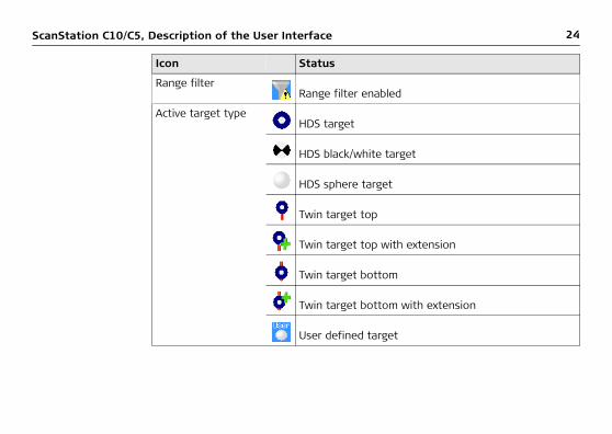
Icon Status
Range filterRange filter enabled
Active target typeHDS target
HDS black/white target
HDS sphere target
Twin target top
Twin target top with extension
Twin target bottom
Twin target bottom with extension
User defined target

ScanStation C10/C5, Description of the User Interface 25
Dual-axis compen-sator On and levelled
Off
On but out of range
WiFi WiFi adapter connected to scanner and ready for communication.
External camera External camera connected and selected for image acquisition.
External camera connected but not selected for image acquisition.
Internal hard discEmpty
13% memory used
25% memory used
38% memory used
Icon Status

26ScanStation C10/C5, Description of the User Interface
50% memory used
63% memory used
75% memory used
88% memory used
Full
Status of external memory
Ready to be removed.
Do not remove!
External memory Empty
17% memory used
33% memory used
50% memory used
67% memory used
Icon Status

ScanStation C10/C5, Description of the User Interface 27
83% memory used
Full
Icon Status
28ScanStation C10/C5, Description of the User Interface
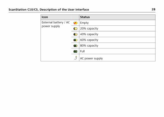
External battery / AC power supply
Empty
20% capacity
40% capacity
60% capacity
80% capacity
Full
AC power supply
Icon Status

ScanStation C10/C5, Description of the User Interface 29
Internal battery A/B Empty
Currently in use - 20% capacity
Currently in use - 40% capacity
Currently in use - 60% capacity
Currently in use - 80% capacity
Currently in use - full
Currently not in use - empty
Currently not in use - 20% capacity
Currently not in use - 40% capacity
Currently not in use - 60% capacity
Currently not in use - 80% capacity
Currently not in use - full
Icon Status

30ScanStation C10/C5, Description of the User Interface
3.4 User Input
Overview The system offers two different virtual keyboards for user input:
1. User input for alphanumeric input fields:When an alphanumeric input field is selected with the stylus, an alphanumeric keypad opens offering letters, numbers and special characters.
a) Alphanumeric input fieldb) Alphanumeric keypadc) Backspaced) Entere) Toggle between letters and
numbers/special charactersf) Shift - Toggle between
lower case and upper case charactersC10_037
a
bc
de
f
ScanStation C10/C5, Description of the User Interface 31
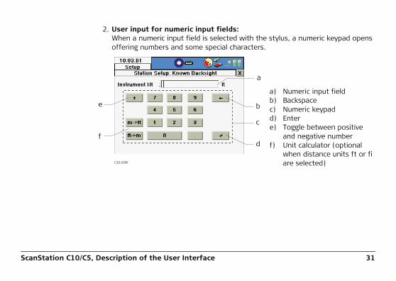
2. User input for numeric input fields:When a numeric input field is selected with the stylus, a numeric keypad opens offering numbers and some special characters.
a) Numeric input fieldb) Backspacec) Numeric keypadd) Entere) Toggle between positive
and negative numberf) Unit calculator (optional
when distance units ft or fi are selected)C10_038
a
c
b
d
e
f

32ScanStation C10/C5, Switching the System On/Off
4 Switching the System On/Off
Switch on procedure
1. Set up the instrument as desired. Refer to chapter "2 Setting Up the Instrument" for more information.
2. Press and hold the ON/OFF button until a beep is audible.3. The instrument’s fan starts.4. The Leica Geosystems welcome screen starts.5. Wait until the Main Menu appears on the display and the Idle State message is
shown in the message bar.6. Once in Idle State the scanner is ready for operation.
Switch off procedure
1. From the current menu return to the Main Menu.
2. In the Main Menu press the button.3. In the popup window confirm the question
Do you really want to power down the scanner? with Yes.4. Wait for the scanner to shut down.

ScanStation C10/C5, Switching the System On/Off 33
Alternative switch off procedure
In the event of a system crash follow the alternative switch off procedure:1. Press and hold the ON/OFF button for a minimum of 6 seconds.2. After 3 seconds a single beep and after 6 seconds a double beep is audible.3. After the double beep release the ON/OFF button.4. Wait for the scanner to shut down.
34ScanStation C10/C5, Remote Control
5 Remote ControlOverview The ScanStation C10/C5 can be controlled remotely by a Viva Controller via WiFi
communication.The following hardware is needed:• Viva Controller (CS10 or CS15) equipped with a WiFi adapter. Check the sticker
This device contains… in the battery compartment of the Viva Controller: In case a WLAN module is listed, the controller is equipped with a WiFi adapter.
• Windy31 wireless USB router.
Installation of the ScanStation C10/C5 Remote Control Application on the Leica Viva Controller
1. Copy the installation file C10_RemoteControl.CAB onto a USB memory device.2. Switch on the Viva Controller and connect the USB memory device to the
controller.3. In case SmartWorx Viva application is running, close this application by pressing
Fn -> Exit.4. Double-click My Device and navigate to the USB memory device.5. Double-click the file C10_RemoteControl.CAB.6. Confirm the suggested installation folder Program Files by pressing OK within
the Install Leica Geosystems AG C10 … dialog.7. The application will be installed. A start-up menu folder as well as a desktop icon
will be created.8. Disconnect the USB memory device.

ScanStation C10/C5, Remote Control 35
Enable the WiFi adapter of your Viva Controller
1. Go to Start -> Settings -> Control Panel.2. Double-click on Network and Dial-up Connections.3. Select the icon of the WiFi device (e. g. NXPWLAN1) and press File. If the menu
lists Disable, the WiFi device is already enabled. In this case leave the control panel without any changes. If the menu lists Enable, press Enable and leave the control panel.
4. Close the control panel.
ScanStation C10/C5 Remote Control
1. Switch on the ScanStation C10/C5 and connect the Windy31 wireless router.2. Wait for the WiFi adapter to finish its configuration. This may take up to two
minutes.3. Start the ScanStation C10/C5 Remote Control application on your Viva Controller
by double-clicking the desktop icon.4. Within the ScanStation C10/C5 Remote Control dialog press Find scanner and
wait for your ScanStation C10/C5 to be listed within the list of available scanners.5. As soon as your ScanStation C10/C5 is listed, select it and press Connect.6. Wait until the ScanStation C10/C5 onboard control is displayed on your Viva
Controller.7. Close the ScanStation C10/C5 Remote Control window as well as the
ScanStation C10/C5 Remote Control dialog by pressing in the respective dialog.

36ScanStation C10/C5, Remote Control
The USB port of the Viva Controller will not replace the USB port of the ScanStation C10/C5 while you are connected to the scanner. In order to download scanning projects, upload control point files or system files you always have to use the USB port of the ScanStation C10/C5.
Since the Viva Controller CS10 has a screen in upright format the C10 Remote Control application offers the option to rotate the onboard control by 90° on the controller's screen. In order to activate the 90°-rotation, select Rotate screen. This option is not available on the Viva Controller CS15.
For details about the CS10/CS15 controllers refer to the CS10/CS15 user manual.

ScanStation C10/C5, Remote Control 37

38ScanStation C10/C5, Main Menu
6 Main Menu
Description The Main Menu will be displayed after the system boot process. Idle State in the message bar indicates that the instrument is ready for scanning.
Main Menu screen

ScanStation C10/C5, Main Menu 39
Icon Function
Scan Offers access to all commands for scanner setup and operation control.
Favorite Scan Starts scan immediately with pre-defined setting.
Manage Offers access to all commands for project, target and control point management.
Status Offers access to all commands for the scanner’s status information.
Config Offers access to all commands for the configuration of the system.
Tools Offers access to all commands for disc formatting, data transfer, license management and display calibration.

40ScanStation C10/C5, Main Menu
Menu independent commands:
Command Function
Escape Return to previous menu in menu hierarchy.
Shift -> Quit Return to main menu.
Page Switch between pages in a menu.

ScanStation C10/C5, Main Menu 41

42ScanStation C10/C5, Scan
7 Scan
Access Select Main Menu, Scan .
Description In the Scan menu all commands for the scanner setup and operation control are available.
7.1 Scan\Scan Begin
Access Select Main Menu, Scan .
Description Scan data is stored on the ScanStation C10/C5 by projects which contain stations for each scanner position. In the Scan Begin screen a new project can be created or an existing project can be selected. For a chosen project a new station can be defined by various setup methods (Standard, Quick Orientation, Set Azimuth, Known Back-sight or Resection) or an existing one can be used to continue.

ScanStation C10/C5, Scan 43
Scan Begin screen
Field Description
Project Shows the current project. Click the name field to open the Manage, Projects screen for selecting another project, adding a new project, editing or deleting an existing project, and displaying project details.

44ScanStation C10/C5, Scan
Available commands:
Command Function
Cont Continue with the current project. Opens the Current Station Information window.
Setup Opens the Station Setup screen for station setup viaQuick Orientation, Set Azimuth, Known Backsight or Resection.
StdStp Create a new station with standard setup parameters (Northing, Easting, Height, Instrument height = 0). Opens the Scan Parameter screen.
ChkBS Open Check Backsight screen to define a known backsight target for current setup control.
Shift -> Conf Open the Setup Configuration screen to define limits and attributes of the various setup methods.

ScanStation C10/C5, Scan 45
7.2 Scan\Setup
Access Select Main Menu, Scan .
Description In the Scan, Scan Begin screen various methods for station setup can be chosen:1. Standard Setup2. Quick Orientation3. Set Azimuth4. Known Backsight5. Resection (by 4 or 6 parameter transformation)
7.2.1 Scan\Setup\Standard Setup
Access Select Main Menu, Scan , StdStp.

46ScanStation C10/C5, Scan
Description The command StdStp in the Scan Begin screen creates a new station with standard setup parameters and proceeds to the Scan Parameter screen.
When Stn ID & Ht in Setup Configuration, StdStp has been set to By User, the command StdStp in Scan Begin opens the Standard Station Setup screen where user-defined station ID and instrument height can be entered before proceeding to the Scan Parameter screen.
7.2.2 Scan\Setup\Quick Orientation
Access Select Main Menu, Scan , Setup.
Description The Quick Orientation setup option offers scanner setup over a known control point and azimuth definition without aiming at a target.
Station Parameter Value for Standard Setup
Northing 0
Easting 0
Height 0
Instrument Height 0
Bearing Current bearing of glass circle.

ScanStation C10/C5, Scan 47
Station Setup: Quick Orientation
Field Description
Station Project Select the project which contains the current station control point.
Station ID Select the station ID of the current station.
Instrument Ht Enter the instrument height (control point to tilt axis).
Azimuth Enter the azimuth to define the orientation of the project coordinate system.

48ScanStation C10/C5, Scan
Command Function
Set Accept station setup and proceed to Scan Parameter screen.
Az=0 Set the Azimuth = 0.
New Opens the New Control Point screen to create a new control point in the selected project.
ChkExp Opens video camera window to check and adjust exposure time to set exposure time manually.
PickAz Select azimuth direction from the video image.
Page Switch to the Set Az page.

ScanStation C10/C5, Scan 49
7.2.3 Scan\Setup\Set Azimuth
Access Select Main Menu, Scan , Setup.
Description The Set Azimuth setup option offers scanner setup over a known control point and azimuth definition by aiming at a backsight target.
Station Setup: Set Azimuth screen

50ScanStation C10/C5, Scan
Field Description
Station Project Select the project which contains the current station control point.
Station ID Select the station ID of the current station.
Instrument Ht Enter the instrument height (control point to tilt axis).
Command Function
Cont Confirm station input and continue with DefineBacksight: Set Azimuth.
Conf Opens the General tab in Setup Configuration where a reminder for the station information can be enabled/disa-bled.
• Yes: Current Setup Information will be displayed every time the Cont button is pressed within the Scan Begin panel
• No: No Current Setup Information panel reminder
New Opens the New Control Point screen to create a new control point in the selected project.
Page Switch to the Known BS page.

ScanStation C10/C5, Scan 51
Define Backsight: Set Azimuth screen
Field Description
Backsight ID Enter the target ID of a new backsight target.
Target Height Enter the target height of the selected backsight target.
Target Type Enter the target type of the selected backsight target.
Azimuth Enter the azimuth to define the orientation of the project coordinate system.

52ScanStation C10/C5, Scan
Command Function
Calc Execute backsight target scan and setup calculation. Show results in Set Azimuth Results screen.
List Change the screen to select a known backsight target from an existing control point project.
Az=0 Set the Azimuth = 0.
ChkExp Open video camera window to check and adjust exposure time for manual exposure time setting.
PickT Select target from the video image. After selection, the target is listed on the Target List page.
Page Switch to the Target List page.

ScanStation C10/C5, Scan 53
Define Backsight: Set Azimuth screen
Field Description
Backsight ID Shows the target ID of a new backsight target after PickT was executed.
Target Type Shows the target type of the selected backsight target after PickT was executed.

54ScanStation C10/C5, Scan
Set Azimuth Results screen
Command Function
Calc Start backsight target scan to selected target and setup calculation. Show results in Set Azimuth Results screen.
Del Delete selected target from the target list.
Page Switch to the Target Def page.

ScanStation C10/C5, Scan 55
Field Description
Station ID Station ID of current station.
InstrumentHeight Instrument height as entered by the user.
Backsight ID Target ID of the selected backsight target.
Target Height Target height as entered by the user.
Target Type Target type of the selected backsight target.
Horiz Dist Horizontal distance between station and backsight target.
Command Function
Set Accept the setup results for this station and proceed to Scan Parameter screen.
View View point cloud of selected backsight target scan.
Page Switch to the Tgt Coords page.
Shift -> Redo Repeat backsight target scan to selected target and setup calculation.
56ScanStation C10/C5, Scan
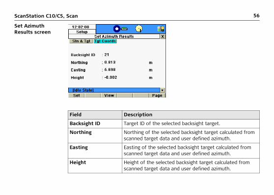
Set Azimuth Results screen
Field Description
Backsight ID Target ID of the selected backsight target.
Northing Northing of the selected backsight target calculated from scanned target data and user defined azimuth.
Easting Easting of the selected backsight target calculated from scanned target data and user defined azimuth.
Height Height of the selected backsight target calculated from scanned target data and user defined azimuth.

ScanStation C10/C5, Scan 57
Command Function
Set Accept the setup results for this station and proceed to Scan Parameter screen.
View View point cloud of selected backsight target scan.
Page Switch to the Stn & Tgt page.

58ScanStation C10/C5, Scan
7.2.4 Scan\Setup\Known Backsight
Access Select Main Menu, Scan , Setup and switch to Known BS tab.
Description The Known Backsight setup option offers scanner setup over a known control point and scanner orientation by aiming at a known backsight target.
Station Setup: Known Backsight screen

ScanStation C10/C5, Scan 59
Field Description
Station Project Select the project which contains the current station control point.
Station ID Select the station ID of the current station.
Instrument Ht Enter the instrument height (control point to tilt axis).
Command Function
Cont Confirm station input and continue with Define Backsight: Known Backsight.
Conf Opens the Setup Configuration for the known backsight method.
New Opens the New Control Point screen to create a new control point.
Page Switch to the Resection page.

60ScanStation C10/C5, Scan
Station Setup: Known Backsight screen
Field Description
Ctrl Pt Project Select the control point project which contains the back-sight point.
Backsight ID Enter the ID of the backsight point.
Target Height Enter the height of the backsight target.
Target Type Select the type of the backsight target.

ScanStation C10/C5, Scan 61
Command Function
Calc Execute backsight target scan and setup calculation. Show results in Known Backsight Results screen.
New Opens the New Control Point screen.
ChkExp Open video camera window to check and adjust exposure time for manual exposure time setting.
PickT Select target from the video image. After selection, the target is listed on the Target List page.
Page Switch to the Target List page.

62ScanStation C10/C5, Scan
Station Setup: Known Backsight
Field Description
Backsight ID Shows the point ID of the backsight point after PickT was executed.
Target Type Shows the target type on the backsight point after PickT was executed.

ScanStation C10/C5, Scan 63
Station Setup: Known Backsight Results screen
Command Function
Calc Execute backsight target scan and setup calculation. Show results in Known Backsight Results screen.
Del Delete selected target from the target list.
Page Switch to the Target Def page.

64ScanStation C10/C5, Scan
Field Description
Station ID Station ID of current station.
Instrument Height Instrument height as entered by the user.
Backsight ID Point ID of the backsight point.
Target Height Target height as entered by the user.
Target Type Target type on the backsight point.
Horiz Dist Horizontal distance between station and backsight point.
Command Function
Set Accept the setup results for this station and proceed to Scan Parameter screen.
View View point cloud of backsight target scan.
Page Switch to the Delta page.
Shift -> Redo Rerun backsight target scan and setup calculation.

ScanStation C10/C5, Scan 65
Station Setup: Known Backsight Results screen
Field Description
Backsight ID Point ID of the backsight point.
ΔNorthing Difference in Northing between calculated and measured coordinate.
ΔEasting Difference in Easting between calculated and measured coordinate.
ΔHeight Difference in Height between calculated and measured coordinate.
ΔHoriz Dist Difference in Horizontal Distance between calculated and measured distance.

66ScanStation C10/C5, Scan
Command Function
Set Accept results from Known Backsight station setup and proceed to Scan Parameter screen.
View View point cloud of backsight target scan.
Page Switch to the Stn & Tgt page.
ScanStation C10/C5, Scan 67
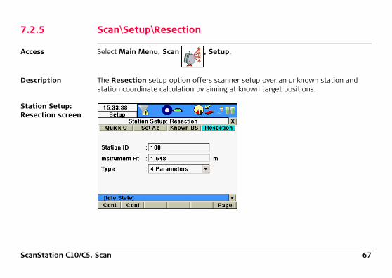
7.2.5 Scan\Setup\Resection
Access Select Main Menu, Scan , Setup.
Description The Resection setup option offers scanner setup over an unknown station and station coordinate calculation by aiming at known target positions.
Station Setup: Resection screen

68ScanStation C10/C5, Scan
Field Description
Station ID Enter the station ID of the current station.
Instrument Ht Enter the instrument height (control point to tilt axis).
Type Chose resection type by 4 or 6 parameter transformation.• 4 Parameters: 3 translations and 1 rotation around
z axis. Min. 2 targets required.• 6 Parameters: 3 translations and 3 rotations.
Min. 3 targets required.
Command Function
Cont Confirm station input and continue with Define Resection Targets.
Conf Opens the Setup Configuration for the resection method.
Page Switch to the Set Az page.

ScanStation C10/C5, Scan 69
Define Resection Targets screen, Target Def
Field Description
Ctrl Pt Project Select the control point project which contains the target coordinates.
Target ID Enter the target ID of a known control point target.
Target Height Enter the target height of the selected control point target.
Target Type Enter the target type of the selected control point target.
No of Targets Number of picked targets to be scanned.

70ScanStation C10/C5, Scan
Command Function
Calc Start target scan to selected targets and setup calculation. Show results in Resection Results screen.
New Change the screen to select a known target from an existing control point project.
ChkExp Open video camera window to check and adjust exposure time for manual exposure time setting.
PickT / Add Select target centre from the video camera image. After selection, the target is listed on the Target List page as a candidate for target acquisition.
When an orientation has already been computed then the additional target can be added from a list by Add and aimed automatically without any target picking.
Page Switch to the Target List page.

ScanStation C10/C5, Scan 71
Define Resection Targets screen, Target List
Field Description
Target ID Shows the target ID of a new target after PickT was executed.
Target Type Shows the target type of the selected target after PickT was executed.

72ScanStation C10/C5, Scan
Resection Results screen, StnCoords
Command Function
Calc Start target scan to selected targets and setup calculation. Show results in Resection Results screen.
Del Delete selected target from the target list.
Page Switch to the Target Def page.

ScanStation C10/C5, Scan 73
Field Description
Station ID Station ID of current station.
InstrumentHeight Instrument height as entered by the user.
No of Targets Number of targets used for resection calculation.
Stn Northing Northing of current station calculated by resection setup.
Stn Easting Easting of current station calculated by resection setup.
Stn Height Height of current station calculated by resection setup.
Command Function
Set Accept the setup results for this station and proceed to Scan Parameter screen.
Page Switch to the Sigma page.

74ScanStation C10/C5, Scan
Resection Results screen, Sigma
Field Description
Station ID Station ID of current station.
σNorthing Standard deviation of station northing.
σEasting Standard deviation of station easting.
σHeight Standard deviation of station height.
σHz Orient Standard deviation of horizontal orientation.

ScanStation C10/C5, Scan 75
Command Function
Set Accept the setup results for this station and proceed to Scan Parameter screen.
Orient / E,N,H For a 6 parameter resection toggle between display of standard deviations for the station coordinates and the 3 rotation angles.
Page Switch to the Target List page.

76ScanStation C10/C5, Scan
Resection Results screen, Target List
Field Description
Target ID Target ID of scanned target.
dN Target residuals dN,dE,dH. Display can be changed by More softkey.
Use Target status for resection calculation (Yes = used, No = not used).

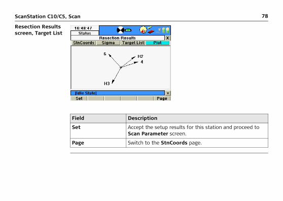
ScanStation C10/C5, Scan 77
Command Function
Set Accept the setup results for this station and proceed to Scan Parameter screen.
Add Switch to Define Resection Targets and define additional targets for resection.
When an orientation has already been computed then the additional target can be aimed automat-ically and no target picking is required.
View View point cloud of selected target scan.
Use Change the target status in the Use field from Yes to No.
More Switch the target residuals display from dN to dE and dH.
Page Switch to the Plot page.
Shift->Redo Repeat target scan to selected target and setup calculation.
78ScanStation C10/C5, Scan
Resection Results screen, Target List
Field Description
Set Accept the setup results for this station and proceed to Scan Parameter screen.
Page Switch to the StnCoords page.

ScanStation C10/C5, Scan 79
7.2.6 Scan\Setup\Setup Confirmation
Access Select Main Menu, Scan , Shift -> Conf.
Description In the Setup Configuration menu the user can configure limits and specifications for the various setup methods.
General page

80ScanStation C10/C5, Scan
Field Options Description
Reminder Yes Enable a reminder for the station informa-tion: Current Setup Information will be displayed every time the Cont button is pressed within the Scan Begin screen.
No Disable the reminder for the station infor-mation.
Command Function
Cont Confirm settings for setup configuration and continue with the Scan Begin screen.
Page Switch to the Resection page.

ScanStation C10/C5, Scan 81
Current Station Information

82ScanStation C10/C5, Scan
Resection page
Field Description
Hz Acc Ori Threshold for standard deviation of horizontal orientation.
Pos Acc Tgt Threshold for the Easting and Northing residuals (ΔE and ΔN) of the targets used in resection.
Ht Acc Tgt Threshold of height residuals (ΔH) of the targets used in re-section.

ScanStation C10/C5, Scan 83
Known BS page
Command Function
Cont Confirm settings for resection setup and continue with the Scan Begin screen.
Page Switch to the Known BS page.

84ScanStation C10/C5, Scan
Field Options Description
Pos Check Yes Enable checking of horizontal coordinate difference (hz range) between existing and measured known backsight point. If defined Pos Limit is exceeded, the setup can be repeated, skipped or stored.
No Disable checking of horizontal coordinate difference between existing and measured known backsight point.
Pos Limit Threshold of horizontal coordinate differ-ence accepted in Pos Check.
Ht Check Yes Enable checking of vertical difference (in z) between existing and measured known backsight point. If defined Ht Limit is exceeded, the setup can be repeated, skipped or stored.
No Disable checking of vertical difference between existing and measured known backsight point.
Ht Limit Threshold of vertical difference accepted in Ht Check.

ScanStation C10/C5, Scan 85
Std Setup page
Command Function
Cont Confirm settings for known backsight setup and continue with the Scan Begin screen.
Page Switch to the Std Setup page.

86ScanStation C10/C5, Scan
Field Options Description
Reminder No No reminder asks for a new station when scans, targets or images are added to an existing station with data in it.
Yes When scans, targets or images are created in an existing station with data in it, a reminder opens and asks if a new station should be created when:
• the current station has been created by Stdstp
• the current ScanWorld is not empty
Stn ID & Ht Automatic Standard setup Stdstp does not ask for station ID and instrument height but creates new station with standard setup parameter and proceeds to the Scan Parameter screen.
By user Standard setup Stdstp opens the Standard Station Setup screen and asks for user-defined station ID and instrument height before proceeding to the Scan Parameter screen.

ScanStation C10/C5, Scan 87
Standard Station Setup
Command Function
Cont Confirm settings for standard setup and continue with the Scan Begin screen.
Page Switch to the General page.

88ScanStation C10/C5, Scan
7.3 Scan\Scan Parameter
Access Select Main Menu, Scan , Scan Parameter.
Description Once a project and station are chosen, the Scan Parameter menu offers four pages for all kinds of scan and image controls: Fld of View, Resolution, Image Ctrl. and Filters.
Scan Parameter screen

ScanStation C10/C5, Scan 89
7.3.1 Scan\Scan Parameter\Field of View
Access Select Main Menu, Scan , Scan Parameter, Fld of View.
Description In the Fld of View page of the Scan Parameter screen the area to be scanned can be defined by several different methods. For detailed information about the different options and commands that can be executed from this page refer to the descriptions on the following pages.
Fld of View page

90ScanStation C10/C5, Scan
PresetsIn the Presets field the following different predefined settings for the field of view (FoV) are listed.
Field Description
Presets Selection of fixed or user defined area to scan or take pictures.
Left Left limit of the area to scan or take pictures.
Right Right limit of the area to scan or take pictures.
Bottom Bottom limit of the area to scan or take pictures.
Top Top limit of the area to scan or take pictures.
Preset Horizontal FoV [°] Vertical FoV [°]
Custom View User defined User defined
Quick Scan Defined by Quick Scan aiming User defined (default: -45 to +90)
Rectangle 60x60 60 60
Rectangle 90x90 90 90
Rectangle 360x60 360 60

ScanStation C10/C5, Scan 91
All presets except Custom View and Quick Scan have fixed values for left/right and bottom/top that cannot be edited.
Available commands:
Rectangle 360x90 360 90
Target All 360 270
Preset Horizontal FoV [°] Vertical FoV [°]
Command Function
Sc+Img Start scan and image acquisition* with selected FoV and reso-lution.
Scan Start scan only with selected FoV and resolution, no images.
ScWin Open scan window for area selection from video stream image.
VwSc View point cloud of last scan with zoom, pan and show previous/next functionality.
VwImg View last image with next/previous functionality*.
Page Switch to the Resolution page.

92ScanStation C10/C5, Scan
* Image acquisition is optional for C5.
Quick Scan
Shift -> Target Open the Target Definition screen to select target ID, target height and target type.
Shift -> Image Start image acquisition* with selected FoV, exposure time and image resolution.
Shift -> ChkBS Open Check Backsight screen to define a known backsight target for current setup control.
Command Function

ScanStation C10/C5, Scan 93
In the Quick Scan preset the Left/Right fields show the current scanner direction. For a quick definition of the scan or image FoV aim the scanner in the designated horizontal direction and press the green Unlocked button to lock the current scanner direction for the Left field. The button changes to the red Locked button and the locked value is greyed out. Repeat the procedure for the Right field or unlock again. Then edit the default Bottom and Top fields manually if needed.
Scan Window screen

94ScanStation C10/C5, Scan
Available commands:
Command Function
Continue Continue and return to the Fld of View page of the Scan Parameter screen. The boundaries of a defined scan/image area will be copied into the corresponding fields.
Scan Return to Fld of View page and start a scan only of the specified area.
Scan & Image
Return to Fld of View page and start a scan and image acquisition of the specified area.
Image Start image acquisition of the specified area.
Zoom In Zoom in to the centre of the video camera image.
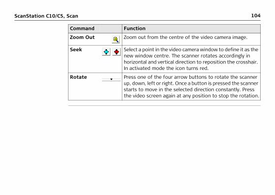
Zoom Out Zoom out from the centre of the video camera image.
Seek Select a point in the video camera window to define it as the new window centre. The scanner rotates accordingly in horizontal and vertical direction to reposition the crosshair. In activated mode the icon turns red.

ScanStation C10/C5, Scan 95
Fence Select the scan/image area by fencing the area in the current video camera image. In activated mode the icon turns red.
Corner Press one of the four corner buttons to define the current position of the crosshair as a corner of a new scan/image area. Orientate the scanner to any other direction and press the opposite corner button to define the opposite corner of the new scan/image area. Once selected the icon turns green.
Rotate Press one of the four arrow buttons to rotate the scanner up, down, left or right. Once a button is pressed the scanner starts to move in the selected direction constantly. Press the video screen again at any position to stop the rotation.
Command Function

96ScanStation C10/C5, Scan
Scanning screen
Field Description
Progress bar Scan progress in percent.
Scan Number of scan.
Est. Time Estimated time to finish scan.

ScanStation C10/C5, Scan 97
Available commands:
View scan screen
Command Function
Pause Pause current scan. Once paused the button changes to Resume. Press again to resume paused scan.
Cancel Cancel current scan and return to the Fld of View menu.

98ScanStation C10/C5, Scan
Available commands:
Command Function
Colourise Switch between coloured and black & white
intensity display.
Add Scan Add fenced scan area to Scan List.
View Scan List View Scan List of selected scan areas.
Fence Select the scan area by fencing the area. In activated mode the icon turns red.
Pan Pan mode to move current scan on screen. In activated mode the icon turns red.
Continue Continue and return to Fld of View menu.
Scan Return to Fld of View menu and start a scan only of all scan areas as listed in the Scan List.
Scan & Image Return to Fld of View menu and start scan and image acquisition of all scan areas as listed in the Scan List.
Image Start image acquisition of all scan areas as listed in the Scan List.

ScanStation C10/C5, Scan 99
Multiple scan areas can be added to the scan list. They are all scanned with the current resolution setting as defined in Resolution tab of the Scan Parameter screen.
Zoom In Zoom in to the centre of the scan image.
Zoom Out Zoom out from the centre of the scan image.
Zoom 1:1 Zoom back to fit complete scan to screen.
Next Show next scan of current station.
Previous Show previous scan of current station.
Command Function

100ScanStation C10/C5, Scan
7.3.2 Scan\Scan Parameter\Resolution
Access Select Main Menu, Scan , Scan Parameter, Resolution.
Description In the Resolution page of the Scan Parameter screen the horizontal and vertical point spacing can be defined by several different methods. For detailed information about the different options and commands that can be executed from this page refer to the descriptions on the following pages.
Resolution page

ScanStation C10/C5, Scan 101
Resolution settings:
Field Description
Resolution Selection of fixed or user defined resolution settings.
Distance Distance for which the horizontal and vertical resolution apply.
Horizontal Horizontal resolution at given distance.
Vertical Vertical resolution at given distance.
No Pts Hz x V Number of points in horizontal and vertical direction for specified resolution.
Setting Horizontal spacing
Vertical spacing Range
Custom Res User defined(0.5 m default)
User defined(0.5 m default)
User defined(100 m default)
Low Res 0.2 m 0.2 m 100 m
Medium Res 0.1 m 0.1 m 100 m
High Res 0.05 m 0.05 m 100 m
Highest Res 0.02 m 0.02 m 100 m

102ScanStation C10/C5, Scan
Available commands:
* Image acquisition is optional for C5.
Command Function
Sc+Img Start scan and image acquisition* with selected FoV and resolu-tion.
Scan Start scan only with selected FoV and resolution, no images.
ScWin Open scan window for area selection from video stream image.
Dist Open video camera window to measure the distance to the object to be scanned.
Page Switch to the Image Ctrl page.
Shift -> Target Open the Target Definition menu to select target ID, target height and target type.
Shift -> Image Start image acquisition* with selected FoV, exposure time and image resolution.
Shift -> ChkBS Open Check Backsight screen to define a known backsight target for current setup control.

ScanStation C10/C5, Scan 103
Measure Distance screen
Available commands:
Command Function
Dist Measure the distance to the point indicated by the crosshair in the video screen. The measured distance will be copied into the Distance field in the Resolution page of the Scan Parameter screen.
Zoom In Zoom in to the centre of the video camera image.
104ScanStation C10/C5, Scan
Zoom Out Zoom out from the centre of the video camera image.
Seek Select a point in the video camera window to define it as the new window centre. The scanner rotates accordingly in horizontal and vertical direction to reposition the crosshair. In activated mode the icon turns red.
Rotate Press one of the four arrow buttons to rotate the scanner up, down, left or right. Once a button is pressed the scanner starts to move in the selected direction constantly. Press the video screen again at any position to stop the rotation.
Command Function

ScanStation C10/C5, Scan 105
7.3.3 Scan\Scan Parameter\Image Control\Internal Camera
Access Select Main Menu, Scan , Scan Parameter, Image Ctrl, Internal Camera.
Description In the Image Ctrl page of the Scan Parameter screen the parameters of the internal camera can be defined. Please refer to the descriptions on the following pages for detailed information about the different options and commands that can be executed from this page.
Image Ctrl page

106ScanStation C10/C5, Scan
Field Option Description
Used Camera
Internal Camera
Field is visible when external camera is connected, then two options are offered: Internal Camera and <Name of internal camera>
Exposure Automatic Image exposure time for each single image is calculated automatically.
Manual Image exposure time is set manually. See Time field.
Time Exposure time in ms (milliseconds) for manual exposure.
Image Type Compressed Images are stored in compressed J2X format with single image size of approx. 0.5 MB to 0.75 MB. The only supported resolution is 1920 x 1920 pixels.
Uncompressed Images are stored in uncompressed RAW format with single image size of approximately 3.5 MB. Different image resolutions are supported.
Image Res 1920x1920 Set single image resolution to 1920 x 1920 pixels.
960x960 Set single image resolution to 960 x 960 pixels.
640x640 Set single image resolution to 640 x 640 pixels.

ScanStation C10/C5, Scan 107
Available commands:
Command Function
Sc+Img Start scan and image acquisition with selected FoV and resolution.
Scan Start scan only with selected FoV and resolution, no images.
ScWin Open scan window for area selection from video stream image.
VwImg View last image with next/previous functionality.
ChExp Open video camera window to check and adjust exposure time for manual exposure time setting.
Page Switch to the Filters page.
Shift -> Target Open the Target Definition screen to select target ID, target height and target type.
Shift -> Image Start image acquisition with selected FoV, exposure time and image resolution.
Shift -> ChkBS Open Check Backsight screen to define a known backsight target for current setup control.
108ScanStation C10/C5, Scan
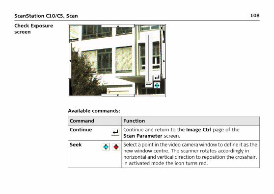
Check Exposure screen
Available commands:
Command Function
Continue Continue and return to the Image Ctrl page of the Scan Parameter screen.
Seek Select a point in the video camera window to define it as the new window centre. The scanner rotates accordingly in horizontal and vertical direction to reposition the crosshair. In activated mode the icon turns red.

ScanStation C10/C5, Scan 109
Capture Images screen
Slider Move slider to adjust exposure time in the video camera window from 0 ms to 800 ms and transfer setting to the Time field of the Image Ctrl page in the Scan Parameter screen.
Rotate Press one of the four arrow buttons to rotate the scanner up, down, left or right. Once a button is pressed the scanner starts to move in the selected direction constantly. Press the video screen again at any position to stop the rotation.
Command Function

110ScanStation C10/C5, Scan
Available commands:
Field Description
Progress bar Image acquisition progress in percent.
Image Number of images already acquired / number of total images to be acquired.
Command Function
Pause Pause current image acquisition process. Once paused the button changes to Resume. Press again to resume paused image acquisition process.
Cancel Cancel the current image acquisition process and return to the Image Ctrl page in the Scan Parameter screen.

ScanStation C10/C5, Scan 111
7.3.4 Scan\Scan Parameter\Image Control\External Camera
Access Select Main Menu, Scan , Scan Parameter, Image Ctrl, External Camera.
Description In the Image Ctrl page of the Scan Parameter screen the parameters of the external camera can be defined. Please refer to the descriptions on the following pages for detailed information about the different options and commands that can be executed from this page.
For details about the external camera setup, the wizard for the initial calcu-lation of interior and exterior camera parameters and the calibration process refer to the External Camera Getting Started document.
To be able to use the external camera the external camera SDK (CanonSDK.add) must be installed (see "11.2 Tools\Transfer") and a valid external camera license must be available (see "11.3 Tools\License").

112ScanStation C10/C5, Scan
Image Ctrl page
Field Option Description
Used Camera
Name of external camera
Serial number of external camera or camera name as entered in the camera calibration process. Reads the camera parameters of the selected camera.

ScanStation C10/C5, Scan 113
Available commands:
Exposure Automatic Image exposure time for each single image is calculated automatically (mode dial on camera is set to Av = Aperture value).
Manual Image exposure time is set manually (mode dial on camera is set to M = Manual). See Time field.
Time Exposure time in ms (milliseconds) for manual exposure.
Command Function
Sc+Img Start scan and image acquisition with selected FoV and resolution.
Scan Start scan only with selected FoV and resolution, no images.
ScWin Open scan window for area selection from video stream image.
VwImg View last image with next/previous functionality.
ChExp With exposure time set to Manual (setting M on the mode dial) the Check Exposure screen opens to check and adjust exposure time on the external camera LCD monitor.
Field Option Description

114ScanStation C10/C5, Scan
Page Switch to the Filters page.
Shift -> Target Open the Target Definition screen to select target ID, target height and target type.
Shift -> Image Start image acquisition with selected FoV, exposure time and image resolution.
Shift -> CamOri Start camera orientation process.
Shift -> ChkBS Open Check Backsight screen to define a known backsight target for current setup control.
Command Function

ScanStation C10/C5, Scan 115
Check Exposure screen
Command Function
Continue Continue and return to the Image Ctrl page of the Scan Pa-rameter screen.
Slider Move slider to adjust exposure time in the external camera LCD monitor and transfer setting to the Time field of the Image Ctrl page in the Scan Parameter screen.

116ScanStation C10/C5, Scan
Capture Images screen
Rotate Press the left or right arrow button to rotate the scanner. The scanner starts to move in the selected direction with a constant movement. Press the video screen again at any position to stop the rotation.
Command Function
Field Description
Progress bar Image acquisition progress in percent.

ScanStation C10/C5, Scan 117
Available commands:
Image Number of images already acquired / number of total images to be acquired.
Command Function
Pause Pause current image acquisition process. Once paused the button changes to Resume. Press again to resume paused image acquisition process.
Cancel Cancel the current image acquisition process and return to the Image Ctrl page in the Scan Parameter screen.
Field Description

118ScanStation C10/C5, Scan
Define External Camera Orienta-tion Targets, page Target Def
Field Description
Target ID Target ID. May include letters such as A-Z, a-z, numbers from 0-9 and any special characters of the virtual keyboard except "[" and "]".
Target Type List of target types which are supported by the scanner.
Target Height Target height in meters from target base point to target centre.

ScanStation C10/C5, Scan 119
Available commands:
Pick From Select the source for target picking. With Video Image selected the PickT command opens the video camera image for target selection. With Scan selected the PickT command opens the scan viewer for target selection.
No of Targets Number of selected targets for the camera orientation process (minimum 1 target to be selected).
Command Function
Cont Continue and start target acquisition process for all targets listed in Target List. These targets will be used for the calcu-lation of the camera orientation.
New Define a new target with target ID, target height and target type. Once pressed the button is labeled List which allows to select again from a drop-down list in the Target field.
ChkExp Open video camera window to check and adjust exposure time for manual exposure time setting.
Field Description

120ScanStation C10/C5, Scan
Define External Camera Orienta-tion Targets, page Target List
PickT Select target centre from the video camera image (Video Image) or from an existing scan (Scan). After selection, the target is listed on the Target List page as a candidate for target acquisition.
Page Switch to the Target List page.
Command Function
ScanStation C10/C5, Scan 121
Available commands:
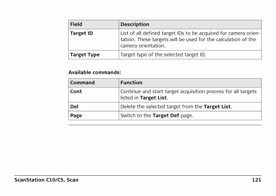
Field Description
Target ID List of all defined target IDs to be acquired for camera orien-tation. These targets will be used for the calculation of the camera orientation.
Target Type Target type of the selected target ID.
Command Function
Cont Continue and start target acquisition process for all targets listed in Target List.
Del Delete the selected target from the Target List.
Page Switch to the Target Def page.

122ScanStation C10/C5, Scan
Define External Camera Orienta-tion Targets, page Results
Field Description
Target ID Target ID of scanned target.
Image Image name with target number and image number.
ΔPix Target residuals to image (in pixels).
Use Target status for calculation of camera orientation (Yes = used, No = not used).

ScanStation C10/C5, Scan 123
Available commands:
Command Function
Store Store external camera orientation results and return to Scan Parameter screen.
VwImg View selected image with next/previous functionality.
ViewT View selected target.
Use Change the target status in the Use field from Yes to No.

124ScanStation C10/C5, Scan
7.3.5 Scan\Scan Parameter\Filters
Access Select Main Menu, Scan , Scan Parameter, Filters
Description In the Filters page of the Scan Parameter screen filters for the minimum and maximum range of scanned points can be set.
Filters page

ScanStation C10/C5, Scan 125
Once range filtering is enabled the icon in the status bar is visible.
At system start the range filtering is disabled by default.
Field Description
Range Filter Enable or disable the range filters.
Min Range Minimum range for point filtering. All points with a range lower than this limit will not be stored.
Max Range Maximum range for filtering. All points with a range higher than this limit will not be stored.
Command Function
Sc+Img Start scan and image acquisition with selected FoV and reso-lution.
Scan Start scan only with selected FoV and resolution, no images.
ScWin Open scan window for area selection from video stream im-age.
MinDis Open video camera window to select a point from video stream image for a probe distance measurement which is entered in the Min Range field.

126ScanStation C10/C5, Scan
MaxDis Open video camera window to select a point from video stream image for a probe distance measurement which is entered in the Max Range field.
Page Switch to the Image Ctrl page.
Shift -> Target Open the Scan, Target Definition menu to select target ID, target height and target type.
Shift -> Image Start image acquisition with selected FoV, exposure time and image resolution
Shift -> ChkBS Open Check Backsight screen to define a known backsight target for current setup control.
Command Function

ScanStation C10/C5, Scan 127
7.3.6 Scan\Scan Parameter\...\Target Definition
Access Select Main Menu, Scan , Scan Parameter,
Fld of View/ Resolution/ ImageCtrl, Shift -> Target or
press the active target icon in the status bar to access the Target Definition screen directly.
Description In the Target Definition screen all options for target acquisition are available.
Target Def page

128ScanStation C10/C5, Scan
Target Type:
Field Description
Target ID Target ID. May include letters such as A-Z, a-z, numbers from 0-9 and any special characters of the virtual keyboard except "[" and "]".
Target Height Target height in meters from target base point to target centre.
Target Type List of target types which are supported by the scanner.
Pick From Select the source for target picking. With Video Image selected the PickT command opens the video camera image for target selection. With Scan selected the PickT command opens the scan viewer for target selection.
Type Description
HDS Tgt 6 inch HDS 6” circular planar target.
HDS Tgt 3 inch HDS 3” x 3”square planar target.
HDS Sphere Tgt HDS 6” spherical target.
HDS B/W Tgt HDS 6” Black&White planar target.

ScanStation C10/C5, Scan 129
Available commands:
Twin Tgt Top Top target of Twin Target Pole without extension. Target height automatically changes to 1.900 m.
Twin Tgt Btm Bottom target of Twin Target Pole without extension. Target height automatically changes to 0.200 m.
Twin Top/Ext Top target of Twin Target Pole with extension. Target height automatically changes to 2.150 m.
Twin Btm/Ext Bottom target of Twin Target Pole with extension. Target height automatically changes to 0.450 m.
Command Function
Cont Continue and start target acquisition process for all targets listed in the Target List page.
New Define a new target with target ID, target height and target type. Once pressed the button is labeled List which allows to select again from a drop-down list in the Target field.
ChkExp Open video camera window to check and adjust exposure time for manual exposure time setting.
Type Description
130ScanStation C10/C5, Scan
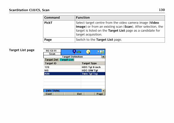
Target List page
PickT Select target centre from the video camera image (Video Image) or from an existing scan (Scan). After selection, the target is listed on the Target List page as a candidate for target acquisition.
Page Switch to the Target List page.
Command Function

ScanStation C10/C5, Scan 131
Available commands:
Field Description
Target ID List of all defined target IDs to be acquired.
Target Type Target type of the selected target ID.
Command Function
Cont Continue and start target acquisition process for all targets listed in Target List.
Del Delete the selected target from the Target List.
Page Switch to the Target Def page.

132ScanStation C10/C5, Scan
Target definition from video page
Command Function
Continue Continue and return to Target Def menu.
Zoom In Zoom in to the centre of the scan image.
Zoom Out Zoom out from the centre of the scan image.

ScanStation C10/C5, Scan 133
Seek Select a point in the video camera window to define it as the new window centre. The scanner rotates accordingly in horizontal and vertical direction to reposition the crosshair. In activated mode the icon turns red.
Fence Select the target scan area by fencing the area.
By pressing the target is scanned with a default reso-lution so that the user can pick the final target scan from the recent scan. In activated mode the icon turns red.
Command Function
134ScanStation C10/C5, Scan
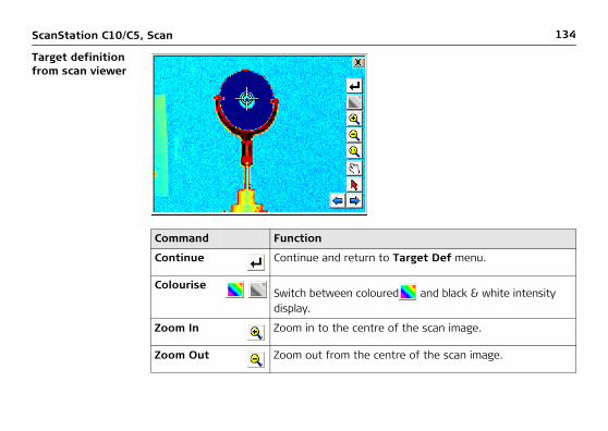
Target definition from scan viewer
Command Function
Continue Continue and return to Target Def menu.
ColouriseSwitch between coloured and black & white intensity display.
Zoom In Zoom in to the centre of the scan image.
Zoom Out Zoom out from the centre of the scan image.

ScanStation C10/C5, Scan 135
Zoom 1:1 Zoom back to fit complete scan to screen.
Pan Pan mode to move current scan on screen. In activated mode the icon turns red.
Pick Pick a point close to the target centre. In activated mode the icon turns red.
Next Show next scan of current station.
Previous Show previous scan of current station.
Command Function

136ScanStation C10/C5, Scan
Target Scan Progress screen
Field Description
Progress bar Current target scan progress in percent.
Target Number of targets already scanned / number of total targets to be scanned.
Est. Time Estimated time to finish current target scan.

ScanStation C10/C5, Scan 137
Available commands:
Target Results screen
Command Function
Pause Pause current target scan process. Once paused the button changes to Resume. Press again to resume paused target scan process.
Cancel Cancel current target scan process and continue to the Target Results screen.

138ScanStation C10/C5, Scan
Available commands:
Field Description
Target ID Target ID of scanned target.
Target Type Target type of scanned target.
Stat Status of scanned target. OK indicates a successful acquisi-tion of the target centre. A bad target centre acquisition is marked as BAD.
Command Function
Store Store all targets listed in the Targets Results list.
Dist Open Distance between Targets screen to measure slope distance between two targets in a ScanWorld.
Info Open Info Targets Results screen with information about the selected target.
Del Delete selected target from the Targets Results list.
View View point cloud of selected target scan.
Shift -> Redo Repeat target scan of target which has been selected in the Target Results list.

ScanStation C10/C5, Scan 139
View Target screen
Available commands:
Command Function
Rotate Rotate the target point cloud counter-clockwise by incre-ments of 30°.
Change colour
Switch between coloured and black & white intensity display.
Zoom In Zoom in to the centre of the scan image.

140ScanStation C10/C5, Scan
Confirmation message
Zoom Out Zoom out from the centre of the scan image.
Zoom 1:1 Zoom back to fit complete target scan to screen.
Command Function

ScanStation C10/C5, Scan 141
Info Target Results screen
Option Description
Yes Confirm deletion of selected target and return to the Targets Results screen.
No Cancel deletion of selected target and return to the Targets Results screen.

142ScanStation C10/C5, Scan
Available commands:
Field Description
Target ID Target ID of selected target.
Target Type Target type of selected target.
Northing Northing of target base point.
Easting Easting of target base point.
Height Height of target base point.
Distance Slope distance from scanner base point to target base point.
Command Function
Cont Continue and return to Target Results screen.

ScanStation C10/C5, Scan 143
Distance between Targets screen
Field Description
From Target Select first target for distance measurement.
To Target Select second target for distance measurement.
Slope Dist Slope distance between selected targets.
Hz Dist Horizontal distance between selected targets.
Ht Diff Height difference between selected targets.

144ScanStation C10/C5, Scan
7.4 Favorite Scan
Access Select Main Menu, Favourite Scan .
Description The Favorite Scan menu starts a scan immediately with user defined settings as configured in the Define Favorite menu (see chapter "10.4 Config\Define Favorite").

ScanStation C10/C5, Scan 145
146ScanStation C10/C5, Manage
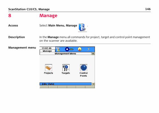
8 Manage
Access Select Main Menu, Manage .
Description In the Manage menu all commands for project, target and control point management on the scanner are available.
Management menu

ScanStation C10/C5, Manage 147
Icon Function
Projects Offers access to all commands for project management.
Targets Offers access to all commands for target management.
Control Points Offers access to all commands for control points management.
148ScanStation C10/C5, Manage
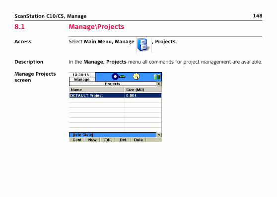
8.1 Manage\Projects
Access Select Main Menu, Manage , Projects.
Description In the Manage, Projects menu all commands for project management are available.
Manage Projects screen

ScanStation C10/C5, Manage 149
Available commands:
Field Description
Name Unique name of the project.
Size (MB) File size (in MB) of the project on the scanner’s hard disc.
Command Function
Cont Confirm selection and return to previous screen.
New Create new project with project name, description, name of creator and storage device.
Edit Edit description and creator of selected project. Also show name, date and size of existing project.
Del Selected project will be deleted after confirmation.
Data Show data details of selected project such as station name, scan name, scan view, target ID, target type and target view.
Shift -> Trans Transfer selected project or all projects to a USB memory storage device.

150ScanStation C10/C5, Manage
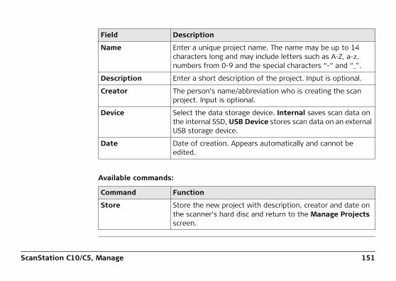
8.1.1 Manage\Projects\New Project
Access Select Main Menu, Manage , Projects, New.
Description In the New Project screen a new project with details such as name, description, creator and storage device can be created.
New Project screen
ScanStation C10/C5, Manage 151
Available commands:
Field Description
Name Enter a unique project name. The name may be up to 14 characters long and may include letters such as A-Z, a-z, numbers from 0-9 and the special characters “-“ and “_”.
Description Enter a short description of the project. Input is optional.
Creator The person’s name/abbreviation who is creating the scan project. Input is optional.
Device Select the data storage device. Internal saves scan data on the internal SSD, USB Device stores scan data on an external USB storage device.
Date Date of creation. Appears automatically and cannot be edited.
Command Function
Store Store the new project with description, creator and date on the scanner’s hard disc and return to the Manage Projects screen.

152ScanStation C10/C5, Manage
8.1.2 Manage\Projects\Edit Project
Access Select Main Menu, Manage , Projects, Edit.
Description In the Edit Project screen the description and creator of the selected project can be changed. Name, storage device, date and size of the selected project are listed but are not editable.
Edit Project screen

ScanStation C10/C5, Manage 153
Available commands:
Field Description
Name Name of selected project. Not editable.
Description Edit/add project description.
Creator Edit/add creator details.
Device Storage device. Not editable.
Date Creation date of selected project. Not editable.
Size File size of selected project. Not editable.
Command Function
Store Store new information and return to the Manage Projects screen.

154ScanStation C10/C5, Manage
8.1.3 Manage\Projects\Delete Project
Access Select Main Menu, Manage , Projects, Del.
Description In the Delete Project screen an existing project can be deleted from the scanner’s hard disc.

ScanStation C10/C5, Manage 155
Confirmation message
Option Description
Yes Confirm deletion of the selected project.
A deleted project cannot be restored.
No Decline deletion of the selected project.

156ScanStation C10/C5, Manage
8.1.4 Manage\Projects\Data
Access Select Main Menu, Manage , Projects, Data.
Despription In the Data screen details of scan data are available such as station name, scan name, target ID, target type and target coordinates. Point clouds of scans and target scans can be viewed.
Select Station/ScanWorld screen

ScanStation C10/C5, Manage 157
Available commands:
Field Description
Station List of available stations in the selected project.
ScanWorld Name of the ScanWorld. A ScanWorld is created for each new Setup. Scans and images that belong to the same coordinate system are combined in a ScanWorld. Several ScanWorlds can belong to the same station.
Command Function
Cont Confirm station selection and continue to Manage Data screen.
Info Open Station Information for details about selected station.

158ScanStation C10/C5, Manage
Scans page
Available commands:
Field Description
Scan All scans from the selected station are listed.
Command Function
View View the point cloud of the selected scan.
Page Switch to the Targets page.

ScanStation C10/C5, Manage 159
Targets page
Field Description
Target ID List of all targets that have been acquired on the selected station.
Target Type The target's associated target type.

160ScanStation C10/C5, Manage
Available commands:
Command Function
View View point cloud of the selected target scan.
Dist Open Distance between Targets screen to measure slope distance between two targets.
Info Show target results of the selected target such as target ID, target type, northing, easting, height and distance from scanner. Coordinates and distances refer to the target base point. For details about the target results refer to chapter "7.3.6 Scan\Scan Parameter\...\Target Definition".
Page Switch to the Images page.

ScanStation C10/C5, Manage 161
Images page
Command Function
View Open image viewer to display the selected image.
Page Switch to the Scans page.

162ScanStation C10/C5, Manage
8.1.5 Manage\Projects\Transfer Project
Access Select Main Menu, Manage , Projects, Shift -> Trans.
Description In the Transfer screen projects can be transferred from the scanner’s hard disc to an external USB memory storage device.Refer to chapter "11.2 Tools\Transfer" for more information.

ScanStation C10/C5, Manage 163
8.2 Manage\Targets
Access Select Main Menu, Manage , Targets
Description In the Manage, Targets menu all commands for target management on the scanner are available.
Manage Targets screen
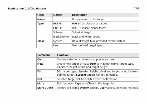
164ScanStation C10/C5, Manage
Field Option Description
Name - Unique name of the target.
Type HDS 6" HDS 6" circular planar target.
HDS 3" HDS 3" square planar target.
Sphere Spherical target.
Black&White Black and White target.
Class System Default target type provided by the system
User User-defined target type.
Command Function
Cont Confirm selection and return to previous screen.
New Create new target of class User with target name, target type, diameter, height offset and target height.
Edit Edit target type, diameter, height offset and target type of a user-defined target. System targets cannot be edited.
Del Selected target will be deleted after confirmation.
More Shift between Type and Class in the target list.
Shift->Deflt Restore all deleted System targets. User targets cannot be restored.

ScanStation C10/C5, Manage 165
8.2.1 Manage\Targets\New Target
Access Select Main Menu, Manage , Targets , New
Description In the New Target menu a new target with details such as name, target type, diam-eter, height offset and target height can be created.
New Target page

166ScanStation C10/C5, Manage
Field Description
Name Enter a unique target name. The name may be up to 16 char-acters long and may include letters such as A-Z, a-z, numbers from 0 -9 and the special characters "-" and "_".
Target Type Enter the target type from a drop-down list to specify the target fitting algorithm.
Diameter Enter the target diameter for a spherical target.
Height Offset Enter a fixed height offset which is added to the target height. Input optional.
Target Ht Enter the default target height. Input optional.
Command Function
Store Store new target with name, target type, diameter, height offset and target height on the scanner's hard disk and return to the Manage Target menu.

ScanStation C10/C5, Manage 167
8.2.2 Manage\Targets\Edit Target
Access Select Main Menu, Manage , Targets , Edit.
Description In the Edit Target menu the target type, diameter, height offset and target height of an existing target can be changed. The name of the selected target is listed but is not editable.
Edit Target page

168ScanStation C10/C5, Manage
Field Description
Name Name of the selected target. Not editable.
Target Type Enter the target type from a drop-down list to specify the target fitting algorithm.
Diameter Edit/add the target diameter for a spherical target.
Height Offset Edit/add the fixed height offset which is added to the target height.
Target Ht Edit/add the default target height.
Command Function
Store Store new information and return to the Manage Targets menu.

ScanStation C10/C5, Manage 169
8.2.3 Manage\Targets\Delete Target
Access Select Main Menu, Manage , Targets , Del.
Description In the Delete Target menu an existing target can be deleted from the target list.
Warning message

170ScanStation C10/C5, Manage
Option Description
Yes Confirm the deletion of the selected target.
A deleted system target can be restored by Shift->Deflt. A deleted user target cannot be restored.
No Decline deletion of the selected target.

ScanStation C10/C5, Manage 171
8.3 Manage\Control Points
Access Select Main Menu, Manage , Control Points .
Description In the Manage, Control Points menu all commands for control points management are available.

172ScanStation C10/C5, Manage
Available commands:
Field Description
Name Unique name of the project.
No of points Number of control points included in the project.
Command Function
Cont Confirm selection and return to previous screen.
New Create new project with project name, description and name of creator.
Edit Edit description and creator of selected project.Also show name, creation date and size of the project.
Del Selected project will be deleted after confirmation.
Imprt Open Import Control Points screen to import control points from ASCII file.
Shift -> Data Open the Control Points list with a list of all control points of the selected project and commands to create, edit, delete or import control points.

ScanStation C10/C5, Manage 173
8.3.1 Manage\Control Points\New Project
Access Select Main Menu, Manage , Control Points , New.
Description Refer to chapter "8.1.1 Manage\Projects\New Project".
8.3.2 Manage\Control Points\Edit Project
Access Select Main Menu, Manage , Control Points , Edit.
Description Refer to chapter "8.1.2 Manage\Projects\Edit Project".
8.3.3 Manage\Control Points\Delete Project
Access Select Main Menu, Manage , Control Points , Del.
Description Refer to chapter "8.1.3 Manage\Projects\Delete Project".

174ScanStation C10/C5, Manage
8.3.4 Manage\Control Points\Import Control Points
Access Select Main Menu, Manage , Control Points , Imprt.
Description In the Import Control Points screen an external ASCII file can be selected for control point import. The import parameters can be defined in the Define ASCII Import screen.

ScanStation C10/C5, Manage 175
The ASCII file must be located in the main directory of the connected USB device. No particular file extension is required.
Field Description
From File Select the ASCII file containing the control points to be imported.
Header Lines Select the number of lines in the ASCII file to be skipped at import.
Command Function
Cont Confirm and import the control points from the selected file.
Conf Open the Define ASCII Import screen to adjust import settings.

176ScanStation C10/C5, Manage
Define ACSII Import
Field Description
Delimiter Select the delimiting character used to separate one column from the next in the ASCII file (Semicolon, Comma, Space, Tab).
Point ID Pos Select the position of the column which contains the point ID information.
Northing Pos Select the position of the column which contains the Northing information.

ScanStation C10/C5, Manage 177
Easting Pos Select the position of the column which contains the Easting information.
Height Pos Select the position of the column which contains the Height information.
Example Shows example of selected import settings (e.g. P;N;E;H).
Command Function
Cont Confirm and return to the Import Control Points screen.
Conf Reset to default import settings (P,E,N,H).
Field Description

178ScanStation C10/C5, Manage
Confirmation message
Option Description
Yes Confirm and return to Import Control Points screen to import more data.
No Decline import of more data and return to Projects screen.

ScanStation C10/C5, Manage 179
8.3.5 Manage\Control Points\Data
Access Select Main Menu, Manage , Control Points , Shift -> Data.
Description In the Manage, Control Points screen all control points of a selected project are listed. For detailed information about the different options and commands that can be executed from this page refer to the descriptions on the following pages.

180ScanStation C10/C5, Manage
Field Description
Point ID Point ID of control point.
Date Date of creation of control point.
Command Function
Cont Continue to Projects screen.
New Create new control point with Point ID, Northing, Easting and Height.
Edit Edit Northing, Easting or Height of selected control point. Also show Point ID of existing control point.
Del Selected control point will be deleted after confirmation.
Imprt Open Import Control Points screen to import control points from ASCII file.
Shift -> D-all All control points of selected project will be deleted after confirmation.

ScanStation C10/C5, Manage 181
8.3.6 Manage\Control Points\Data\New Control Point
Access Select Main Menu, Manage , Control Points , Shift -> Data, New.
Description In the New Control Point screen a new control point can be created by entering Point ID, Northing, Easting and Height.

182ScanStation C10/C5, Manage
Field Description
Point ID Enter Point ID of new control point.
Northing Enter Northing of new control point.
Easting Enter Easting of new control point.
Height Enter Height of new control point.
Command Function
Store Store new information and return to Control Points screen.
ScanStation C10/C5, Manage 183
8.3.7 Manage\Control Points\Data\Edit Control Point
Access Select Main Menu, Manage , Control Points , Shift -> Data, Edit.
Description In the Edit Control Point screen Northing, Easting and Height of the selected control point can be changed. The point ID is listed but is not editable.

184ScanStation C10/C5, Manage
Field Description
Point ID Point ID of selected control point. Not editable.
Northing Northing of selected control point.
Easting Easting of selected control point.
Height Height of selected control point.
Command Function
Store Store new information and return to Control Points screen.

ScanStation C10/C5, Manage 185
8.3.8 Manage\Control Points\Data\Delete Control Point
Access Select Main Menu, Manage , Control Points , Shift -> Data, Del.
Description In the Delete Control Point screen a selected control point can be deleted.
Confirmation message
Option Description
Yes Confirm deletion of selected control point.
A deleted control point cannot be restored.
No Decline deletion of selected control point.

186ScanStation C10/C5, Manage
8.3.9 Manage\Control Points\Data\Import Control Points
Access Select Main Menu, Manage , Control Points , Shift -> Data, Imprt.
Description Refer to chapter "8.3.4 Manage\Control Points\Import Control Points".
8.3.10 Manage\Control Points\Data\Delete All Control Points
Access Select Main Menu, Manage , Control Points , Shift -> Data, Shift D-all.
Description In the Delete All Control Points screen all control points of a project can be deleted.

ScanStation C10/C5, Manage 187
Confirmation message
Option Description
Yes Confirm deletion of all control points in the selected project.
Deleted control points cannot be restored.
No Decline deletion of all control points in the selected project.

212ScanStation C10/C5, Configuration
10 Configuration
Access Select Main Menu, Config .
Description In the Configuration Menu the Units, the local Time & Date, the MMI Language and the Define Favorite scan settings can be configured.
Configuration Menu screen

ScanStation C10/C5, Configuration 213
Icon Command Description
Units Distance Unit
Select unit for distances (Metre, Int Ft, Us Ft).
Distance Dec
Select number of decimal digits for distance display.
Time & Date
Local Time Set local time.
Local Date Set local date.
Language Language Select language for the user interface or delete a language from the list.
Define Favorite Fld of View Select area of interest and scanner action for Favorite Scan.
Resolution Define horizontal and vertical point spacing for Favorite Scan.
Image Ctrl Define parameters of internal camera for Favorite Scan.
Filters Define filter parameters for FavoriteScan.

214ScanStation C10/C5, Configuration
10.1 Config\Units
Access Select Main Menu, Config , Units .
Description In the Units screen linear units and the number of decimals can be defined.
Units screen

ScanStation C10/C5, Configuration 215
Available commands:
Field Option Description
Distance Unit Metre (m) Metre: Uses SI base unit metre.
Int Ft (fi) International feet: Uses 1 ft = 1’ = 12 in. = 1/3 yd = 30.48 cm
US Ft (ft) U.S. survey feet: Uses 39,37 in. = 1 m (1 U.S. survey foot = 1200/3937 m equates approximately 30.48006 cm)
Distance Dec 0 to 3 Decimals
Number of decimal digits for distance related fields.
Command Function
Cont Confirm and return to the Configuration Menu.

216ScanStation C10/C5, Configuration
10.2 Config\Time & Date
Access Select Main Menu, Config , Time & Date .
Description In the Time & Date screen the system time and date can be configured.
Time & Date screen

ScanStation C10/C5, Configuration 217
Available commands:
Field Description
Local Time Enter the local time in the format hh:mm:ss.
Local Date Enter the local date in the format MM/DD/YY.
Command Function
Cont Confirm and return to the Configuration Menu.

218ScanStation C10/C5, Configuration
10.3 Config\Language
Access Select Main Menu, Config , Language .
Description In the Firmware Language screen a list of available languages for the user interface is shown. A language can be selected or deleted from the list.
Additional languages can be installed by uploading language files. Refer to "11.2 Tools\Transfer" for more information.
Firmware Language screen

ScanStation C10/C5, Configuration 219
Available commands:
Field Description
Language List of installed languages on the scanner.
Command Function
Cont Activate the selected language and return to the Main Menu.
Del Delete the selected language. English is part of the firmware and cannot be deleted.

220ScanStation C10/C5, Configuration
10.4 Config\Define Favorite
Access Select Main Menu, Config, Define Favorite .
Description In the Scan, Define Favorite menu the settings for the Favorite Scan menu can be defined.
Fld of View page

ScanStation C10/C5, Configuration 221
Field Option Description
Presets Rectang 60 x 60 Set the Field of View to 60° x 60° (Hz x V).
Rectang 90 x 90 Set the Field of View to 90° x 90° (Hz x V).
Panorama 360 x 60
Set the Field of View to 360° x 60° (Hz x V).
Panorama 360 x 90
Set the Field of View to 360° x 90° (Hz x V).
Target All Set the Field of View to 360° x 270° (Hz x V).
Acquire Scan only Acquire scans only.
Scan + Image Acquire scans and images.
Image only Acquire images only.

222ScanStation C10/C5, Configuration
Resolution page
Refer to chapter "7.3.2 Scan\Scan Parameter\Resolution" for the Resolution settings.

ScanStation C10/C5, Configuration 223
Image Ctrl page
Refer to chapter "7.3.3 Scan\Scan Parameter\Image Control\Internal Camera" for the Image Control settings.
The external camera cannot be configured in the Image Control settings of the Define Favorite menu.

224ScanStation C10/C5, Configuration
Filters page
Field Description
Range Filter Enable or disable the range filters.
Min Range Minimum range for point filtering. All points with a range lower than this limit will not be stored.
Max Range Maximum range for filtering. All points with a range higher than this limit will not be stored.

ScanStation C10/C5, Configuration 225
Once a Favorite Scan with range filtering enabled is started the icon in the status bar is visible.Filter settings for the Favorite Scan do not affect the general filter settings
Available commands in all Define Favorite tabs:
Command Function
Set Store the selected settings for the Favorite Scan menu and return to the Configuration Menu.

188ScanStation C10/C5, Status
9 Status
Access Select Main Menu, Status .
Description The Status Menu provides general status information about different components of the scanner such as battery and memory, general system information, level and laser plummet and WiFi status information.
Status Menu screen

ScanStation C10/C5, Status 189
Icon Command Description
Battery & Memory
Battery Status information about internal battery, external battery and AC power supply.
Memory Status information about size and free space of internal hard disc’s data partition.
System Informa-tion
Instrument Status information about instrument type, serial number, equipment number and system language.
Firmware Status information about installed firmware version and firmware maintenance expiry date.
Options Status information about the installed external camera option and installed set of options on a C5.
Level & Ls Plummet
Level Numerical and graphical display of instrument's tilt.
Plummet Switch laser plummet on/off.
Compens Switch dual-axis compensator* on/off. Define how scanner should react when compensator goes out of range.

190ScanStation C10/C5, Status
* Optional for C5.
WiFi WiFi Define region code and TX power for external WiFi communication device. The WiFi device should be connected to the scanner before this function is selected.
Icon Command Description

ScanStation C10/C5, Status 191
9.1 Status\Battery & Memory
Access • Select Main Menu, Status , Battery & Memory .
OR
• Press one of the power icons in the status bar to access the Battery
page directly.OR
• Press the memory icon in the status bar to access the Memory page
directly.
Description In the Status, Battery & Memory screen detailed information about the scanner’s battery and memory status can be obtained.

192ScanStation C10/C5, Status
Battery page
The battery status is also indicated by the power icons in the status bar.Refer to "3.3 Status Bar" for more information.
Field Description
Battery A Percentage of remaining power of battery A in compartment on scanner’s front side (the side with touch screen).
Battery B Percentage of remaining power of battery B in compartment on scanner’s reverse side (the side without touch screen).
Ext Battery Percentage of remaining power of external battery.
ScanStation C10/C5, Status 193
Available commands:
Memory page
Command Function
Cont Return to previous menu.
Page Switch to the Memory page.

194ScanStation C10/C5, Status
Available commands:
Field Option Description
Data Size Total space for data storage on data partition of scanner’s hard disc.
Free Free space for data storage on data partition of scanner’s hard disc.
Command Function
Cont Return to previous menu.
Page Switch to the Battery page.

ScanStation C10/C5, Status 195
9.2 Status\System Information
Access Select Main Menu, Status , System Information .
Description The System Information screen provides detailed information about instrument type, serial number, system language and firmware version.
Instrument page

196ScanStation C10/C5, Status
Available commands:
Field Description
Instr Type Instrument type.
Serial No Serial number of the instrument.See also serial number plate on instrument’s bottom side.
Equipm No Leica unique identification code of the instrument.
System Lang Active system language.
Command Function
Cont Return to Status Menu.
Page Switch to the Firmware page.

ScanStation C10/C5, Status 197
Options page
* Optional for C5
Field Description
Ext. Camera Status of the external camera option (Activated/Deactivated).
Extend Rnge * Status of the C5 extended range option (Activated/Deactivated).
Full Speed * Status of the C5 full speed option (Activated/Deactivated).
Tilt Compens * Status of the C5 tilt compensator option (Activated/Deactivated).
Camera * Status of the C5 camera option (Activated/Deactivated).

198ScanStation C10/C5, Status
Available commands:
Firmware page
Command Function
Cont Return to Status Menu.
Page Switch to the Firmware page.

ScanStation C10/C5, Status 199
Available commands:
Field Description
Firmware Firmware version of the installed onboard software.
Maint End Expiry date of firmware maintenance period. All firmware versions with release date prior to this date can be uploaded.
Canon SDK SDK for external camera (Installed/Not installed).
Command Function
Cont Return to Status Menu.
Page Switch to the Instrument page.

200ScanStation C10/C5, Status
9.3 Status\Level & Laser Plummet
Access • Select Main Menu, Status , Level & Ls Plummet .
OR
• Press the compensator icon in the status bar to access the Level page
directly.
Description The Level & Laser Plummet screen provides detailed information about the elec-tronic level, the laser plummet and the compensator settings.
ScanStation C10/C5, Status 201
Level page
Field Option Description
Tilt L - Longitudinal tilt of the vertical axis.
Tilt T - Transversal tilt of the vertical axis.
Bubble Level green Tilt L and Tilt T < 5’, level is within the high accuracy working range of the compensator. The accuracy of the compensator in the ± 5' working range is 1.5''.
red Tilt L or Tilt T > 5’, level is out of the high accuracy working range of the compensator.

202ScanStation C10/C5, Status
As soon as the bubble level colour changes from green (within compensator range) to red (outside of ± 5' compensator range) the compensator icon in the status bar
changes from to .
The level moves linearly with the inclination values Tilt L and Tilt T. It moves down if the value in Tilt L increases and vice versa. It moves left if the value in Tilt T gets bigger and vice versa.
Align the scanner side cover with the touch screen parallel to two of the tribrach footscrews. Rotating these two footscrews then causes the bubble to move only left/right. Rotating the third footscrew causes the bubble to move only up/down.
1 2
3C10_045

ScanStation C10/C5, Status 203
Available commands:
Plummet page
Command Function
Cont Return to previous menu.
Page Switch to the Plummet page.

204ScanStation C10/C5, Status
By default the laser plummet is Off after system boot.Changing this setting to On turns the laser plummet on immediately. It is only visible when the Level & Laser Plummet screen is active.
Available commands:
Field Option Description
Ls Plummet On Turn the red laser plummet on.
Off Turn the red laser plummet off.
Command Function
Cont Return to previous menu.
Page Switch to the Compens page.

ScanStation C10/C5, Status 205
Compens page*
* Optional for C5. Requires activated Tilt Compensator option for C5.
Field Option Description
Compensator On Turns the compensator on.
Off Turns the compensator off temporarily. After system restart, the compensator will be on again.
Always Off Turns the compensator off. After system restart, the compensator will remain off.

206ScanStation C10/C5, Status
By default the compensator is On after system boot.When changing this setting to Off or Always Off the compensator icon in the status
bar changes to .
Available commands:
Out of Range Cancel scan&img
If the compensator goes out of range, cancel the current scan or image acquisition.
Flag data & cont
If the compensator goes out of range, continue current scan or image acquisition, but flag unlev-eled object for subsequent data import.
Command Function
Cont Return to previous menu.
Page Switch to the Level page.
Field Option Description

ScanStation C10/C5, Status 207
9.4 Status\WiFi
Access Select Main Menu, Status , WiFi .
Description In the WiFi screen the communication parameters of the external WiFi device can be defined. Depending on the local regulations it might be necessary to adjust these parameters.
WiFi screen

208ScanStation C10/C5, Status
Available commands:
Field Option Description
Region Code Region 0(CH1-11)Region 1(CH1-13)Region 2(CH10-11)Region 3(CH10-13)Region 4(CH14)Region 5(CH1-14)Region 6(CH3-9)Region 7(CH5-13)
Restricts the external WiFi device to a particular sub-set of the 802.11 channels. Depending on local regulations the required setting might be different.
TX Power 100%75%50%25%Lowest
Controls the output power of the external WiFi device. At 100% the output power is 100 mW.
Command Function
Cont Confirm and transfer current settings to the connected external WiFi device.

ScanStation C10/C5, Status 209
• Region Code and TX Power settings typically should not need to be changed. The scanner provides these in case there are changes to national laws which regulate the use of the 2.4GHz band. Restrictions of channel use and power have existed in the past and could be reintroduced.
• The following EEA member states apply restrictions on the placing on the market or on the putting into service or require authorisation for use:• France• Italy• Norway (if used in the geographical area within a radius of 20km from the
centre of Ny-Ålesund)• The system supports the Windy31 and Windy31N USB WiFi adapters for wireless
communication.For purchase information of these third-party products contact your local Leica Geosystems dealer
or contact
SYNET Electronics, Inc.201 Gates Road, Unit C, Little Ferry, NJ07643, USAToll Free : 1-866-US-SYNET (877-9638)Tel : (201) 931-1177e-mail : [email protected]

210ScanStation C10/C5, Status
Installing the Windy31/Windy31N USB WiFi adapter
1. After scanner bootup, plug in the Windy31 or Windy31N into the scanner’s USB socket.All files to support the Windy31 or Windy31N USB WiFi adapters are installed with the Leica ScanStation C10/C5 firmware. No additional files need to be installed.
3. Wait for the counter to finish and the message to disappear.4. If required in your country, change the values for Region Code and TX Power
on the WiFi page to your country specific settings and press Cont to transfer the new settings to the USB WiFi adapter.The Windy31 Enabler window appears again. Wait for the counter to finish and the message to disappear.
5. On your laptop computer with Cyclone SCAN installed, activate the wireless network device and connect to network Leica C10 126xxxx WiFi with 126xxxx being the scanner’s serial number.
6. Start Cyclone and connect to the ScanStation C10/C5 wirelessly in the same way as with an Ethernet cable connection.
For details about Cyclone refer to the Cyclone online help menu or the Leica HDS training manual provided by your regional Leica HDS support.
2. After a maximum of 60 sec, the Windy31 Enabler window appears to initialise the USB WiFi adapter with the current settings from the ScanStation C10/C5 WiFi page.

ScanStation C10/C5, Status 211

226ScanStation C10/C5, Tools
11 Tools
Access Select Main Menu, Tools .
Description In the Tools menu all commands for disc formatting, data transfer, license manage-ment and display calibration are available.
Tools Menu screen

ScanStation C10/C5, Tools 227
Icon Command Description
Format Confirma-tion
Format the complete data partition of the internal hard disc.
All project data will be erased.
Transfer Projects Transfer selected project or all projects to a USB memory storage device.
System Files
Upload a new firmware or firmware languages to the instrument.
License Manual Enter license key manually.
Upload Upload license key file from a USB memory storage device.
Display Calibration
Touch Calibration
Recalibrate the touch screen by clicking three points on the display.

228ScanStation C10/C5, Tools
11.1 Tools\Format
Access Select Main Menu, Tools , Format .
Description In the Format screen the data partition of the scanner’s hard disc can be formatted.
Confirmation message

ScanStation C10/C5, Tools 229
• Formatting is irreversible. It is recommended to backup any project files before starting Format.
• The Format command does not affect any system files. Only scan data will be erased.
Option Description
Yes Starts formatting the data partition.
All project data will be erased.
No Cancels the formatting process and returns to the Tools menu.

230ScanStation C10/C5, Tools
11.2 Tools\Transfer
Access Select Main Menu, Tools , Transfer .
Description In the Transfer menu projects can be transferred from the scanner’s hard disc to an external USB memory storage device and new firmware and languages can be uploaded from an external USB memory storage device to the scanner.
Transfer Project screen

ScanStation C10/C5, Tools 231
Available commands:
The file system on the USB memory storage device must be NTFS, FAT32 or FAT.
Field Description
Project Name of the project to be transferred. Touch the name field to open the Manage, Projects menu for selecting another project.
Size File size (in MB) of the selected project.
Command Function
Cont Transfer the selected project to the connected USB memory storage device into the folder \Scan-Projects\Project.
Logs Transfer system log files to the connected USB memory storage device into the folder \Logs.

232ScanStation C10/C5, Tools
Information message
In case that no USB memory storage device has been connected, the following screen will appear:
Please check whether the USB memory storage device has been connected properly and try again.

ScanStation C10/C5, Tools 233
Firmware page
• The firmware file (*.fw) or external camera SDK (CanonSDK.add) must be located in the main directory of the USB memory storage device.
• Firmware files are named for example C10_v1.2.3.456.fw with 1.2 being the firmware version in this case.
Field Description
Firmware Select firmware file (*.fw) or external camera SDK (CanonSDK.add) from connected USB memory storage device.

234ScanStation C10/C5, Tools
• Uploading a new firmware file can take up to 40 min. Ensure sufficient battery power or provide AC power and do not interrupt power supply during the upload process.
• Refer to the document UpdateSSC10_ver2.0.pdf which is enclosed with each new firmware file for detailed instructions.
Available commands:
After the upload process, the instrument restarts two times and then displays the Main Menu.
Command Function
Cont Starts the upload process of the selected firmware file.
Page Switch to the Languages page.

ScanStation C10/C5, Tools 235
Language page
• The language file (*.lng) must be located in the main directory of the USB memory storage device.
Field Description
Language Select language file (*.lng) from connected USB memory storage device.

236ScanStation C10/C5, Tools
Available commands:
After the upload process, the language is available as an additional entry in the Language page of the Firmware Language screen. Refer to chapter "10.3 Config\Language" for more information.
Command Function
Cont Starts the upload process of the selected language file.
Page Switch to the Firmware page.

ScanStation C10/C5, Tools 237
11.3 Tools\License
Access Select Main Menu, Tools , License .
Description In the License screen the firmware maintenance license key can be entered manually or uploaded via key file. A valid license key is required to be able to update the ScanStation C10/C5 firmware.
Manual page

238ScanStation C10/C5, Tools
Available commands:
Field Description
Key Enter the 14-digit license key manually.
The license key is not case sensitive.
Command Function
Cont Confirm the entered license key.
Page Switch to the Upload page.

ScanStation C10/C5, Tools 239
Upload page
Field Description
Key File Select the license key file (*.key) from the connected USB memory storage device to load onto the scanner.
• The license key file (*.key) must be located in the main directory of the USB memory storage device.
• License key files are named for example "L_126xxxx.key" with 126xxxx being the scanner’s serial number.

240ScanStation C10/C5, Tools
Available commands:
Command Function
Cont Confirm and load the license key from the selected license key file.
Page Switch to the Manual page.

ScanStation C10/C5, Tools 241
11.4 Tools\Display Calibration
Access Select Main Menu, Tools , Display Calibration .
Description In the Display Calibration menu the onboard touch screen can be calibrated.
Confirmation message

242ScanStation C10/C5, Tools
Option Description
Yes Start the touch screen calibration process. Then click the centres of three calibration points which appear consecutively on the display.
No Cancel the touch screen calibration process and return to the Tools menu.

ScanStation C10/C5, Tools 243

244ScanStation C10/C5, Index
Index
AAC power supply ........................................... 23, 28Arrow buttons .................................... 95, 104, 109Azimuth .............................................................. 49
BBacksight ............................................................ 58Battery, external ........................... 23, 28, 189, 192Battery, internal ............................ 23, 29, 189, 192
CCamera, external
Scan Parameter, Image Control .................... 111Camera, internal
Scan Parameter, Image Control .................... 105Check Backsight ............................ 44, 92, 102, 107Check exposure ................. 102, 106, 107, 108, 113Circular level ................................................. 14, 17Compensator, dual-axis .........15, 25, 200, 201, 205Control point ........................................ 39, 50, 147Control Points ................................................... 171
DDistance ....................................................101, 142Distance, measure .....................................102, 103
EExposure, Automatic .................................106, 113Exposure, Manual ......................................106, 113External memory .................................................26
FFavorite Scan ....................................................144
Define Favorite ............................................220Menu ...........................................................144
Field of view (FoV) ..............................................90Horizontal ......................................................90Vertical ...........................................................90
Filter ...................................................88, 124, 224Filters ................................................................124Firmware ...................................189, 195, 199, 210
Firmware file ................................................233Firmware language ...............................218, 227Firmware upload ..........................................230

ScanStation C10/C5, Index 245
IImage control ..................................................... 88Image resolution ............................................... 101Instrument height ............................................... 18Internal hard disc ................................................ 25
KKeyboard, virtual ................................................. 30Known Backsight .......................................... 44, 58
LLanguage .................................................. 218, 227
Language file ............................................... 235Language upload ......................................... 230
Laser plummet ......................15, 17, 189, 200, 204Level .....................................14, 17, 189, 200, 201License ..................................................... 227, 237
License key .......................................... 237, 238License key file ............................................ 239License key file upload ................................. 239
MMaintenance ............................................. 199, 237Memory, external ................................................ 26Message bar ....................................................... 21
QQuick Orientation ........................42, 44, 45, 46, 47Quick Scan ....................................................90, 93
RRange ...............................................................101Range filter ...................................................23, 24Remote Control .......................................34, 35, 36Resection Results screen .....................................72Resection setup ..................................................67
SSerial number ................................2, 195, 210, 239Set Azimuth ..................................................44, 49Set up the tripod ...........................................13, 16Spacing, horizontal ............................................101Spacing, vertical ................................................101Station Setup ......................................................44Status bar .............................21, 23, 191, 200, 206System date ......................................................217System time ................................................21, 217
TTarget .........................................92, 127, 130, 136
Target height .........................92, 102, 128, 129

246ScanStation C10/C5, Index
Target ID ...................... 102, 128, 131, 156, 159Target list .................................................... 130Target results .............................. 137, 141, 160Target scan .................................................. 136Target type ............24, 102, 128, 131, 156, 159
Target, view ...................................................... 139Targets ............................................................. 163Title bar .............................................................. 21Transport container ............................................ 10Tripod ..................................................... 12, 13, 16Twin target ................................................. 24, 129
UUnit, distance ................................................... 215USB memory storage device .............. 149, 230, 233
File system .................................................. 231USB socket ................................................. 20, 210USB WiFi adapter .............................................. 210
VViva Controller .................................................... 34
WWeight ................................................................ 10WiFi .......................................................... 190, 207
Communication device ..................................190Output power ..............................................208Region code .................................................208USB WiFi Adapter .........................................210

ScanStation C10/C5, Index 247

7812
84-5
.0.0
en O
rigin
al t
ext
Prin
ted
in S
witz
erla
nd ©
201
2 Le
ica
Geo
syst
ems
AG, H
eerb
rugg
, Sw
itzer
land
Leica Geosystems AGHeinrich-Wild-StrasseCH-9435 HeerbruggSwitzerlandPhone +41 71 727 31 31www.leica-geosystems.com