Leica M Stereo- microscopes - UCSF Macromolecular ... · joy the quality and performance of Leica...
73
Leica M Stereo- microscopes User Manual
Transcript of Leica M Stereo- microscopes - UCSF Macromolecular ... · joy the quality and performance of Leica...
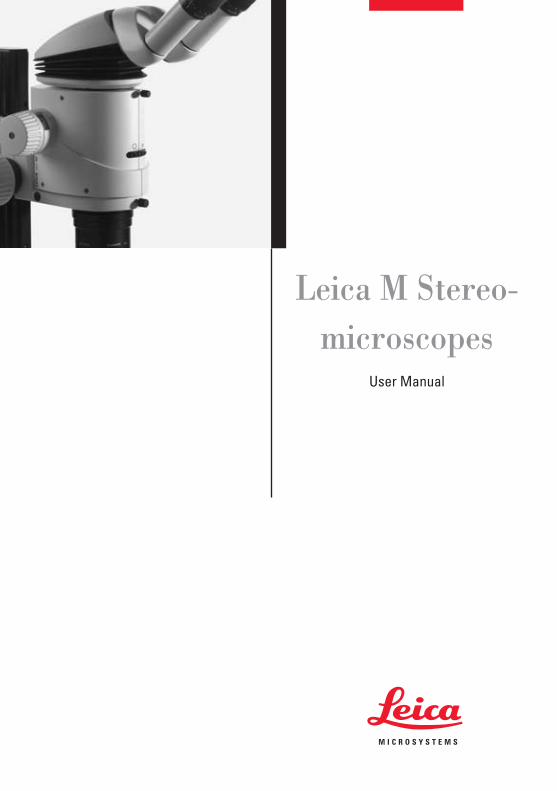
Leica M Stereo-microscopes
User Manual
3Leica M Stereomicroscopes User Manual
Dear User
Thank you for choosing our products. We hope that you will en-joy the quality and performance of Leica Microsystems products.
In developing our instruments, we have placed great emphasison simple, self-explanatory directions. In order to utilize all thebenefits of your new stereomicroscope, we suggest studyingthis user manual in detail. Should you have any questions, pleaseconsult your local Leica representative. You will find the addressof the closest local representative as well as valuable informa-tion about products and services from Leica Microsystems onour homepage at www.leica-microsystems.comWe are gladly at your service. Customer service is a big thingwith us. Not only before the sale, but afterwards as well.
Leica Microsystems (Switzerland) LtdStereo & Macroscope Systemswww.stereomicroscopy.com
User ManualYour instrument is accompanied by a printed English user man-ual. Additional language versions and information can be foundon the interactive CD-ROM. User manuals and updates areavailable for download on our homepage at www.stereomicroscopy.com.
This user manual contains an explanation of the safety regula-tions, assembly, handling and accessories of the Leica MS5,MZ6, MZ75, MZ95, MZ125, MZ16, MZ16 A and MZ16 FA(if identical) stereomicroscopes. The special functions of theautomated stereomicroscopes Leica MZ16 A and MZ16 FA canbe found in separate user manuals.
Leica M Stereomicroscopes User Manual
Table of contents
4
PageOverviewSafety concept . . . . . . . . . . . . . . . . . . . . . . . . . . . . . . . . . . . . . . . . . . 6Symbols . . . . . . . . . . . . . . . . . . . . . . . . . . . . . . . . . . . . . . . . . . . . . . . . 9Controls and functions . . . . . . . . . . . . . . . . . . . . . . . . . . . . . . . . . . 10
UseChanging the magnification . . . . . . . . . . . . . . . . . . . . . . . . . . . . . . 12Ergonomics . . . . . . . . . . . . . . . . . . . . . . . . . . . . . . . . . . . . . . . . . . . . 14Interpupillary distance . . . . . . . . . . . . . . . . . . . . . . . . . . . . . . . . . . 15Eyepoint . . . . . . . . . . . . . . . . . . . . . . . . . . . . . . . . . . . . . . . . . . . . . . 15Eye contact, eyecups . . . . . . . . . . . . . . . . . . . . . . . . . . . . . . . . . . . 16Focusing . . . . . . . . . . . . . . . . . . . . . . . . . . . . . . . . . . . . . . . . . . . . . . 16Microscope carrier: Stereoscopic and axial observation . . . . 18Diopter settings . . . . . . . . . . . . . . . . . . . . . . . . . . . . . . . . . . . . . . . . 20
Assembly Overview: Components . . . . . . . . . . . . . . . . . . . . . . . . . . . . . . . . . . 22
StandProfile column for incident light and transmitted-light stands . . 23Transmitted-light stand, bright field, 20 W . . . . . . . . . . . . . . . . . . 23Transmitted-light stand, bright and dark field . . . . . . . . . . . . . . . 26Transmitted-light stand HL . . . . . . . . . . . . . . . . . . . . . . . . . . . . . . . 27Swinging-arm stand ESD . . . . . . . . . . . . . . . . . . . . . . . . . . . . . . . . 28Large swinging-arm and table-clamp stands . . . . . . . . . . . . . . . 30
Optics carrier, optical accessoriesSpacer rings, objective combinations . . . . . . . . . . . . . . . . . . . . . 32Microscope carrier . . . . . . . . . . . . . . . . . . . . . . . . . . . . . . . . . . . . . 34Optics carrier . . . . . . . . . . . . . . . . . . . . . . . . . . . . . . . . . . . . . . . . . . 34Binocular tubes, optical accessories . . . . . . . . . . . . . . . . . . . . . . 35Objective nosepiece (MZ16 and MZ16 A) . . . . . . . . . . . . . . . . . . 36
5
PageIlluminatorsTransformers . . . . . . . . . . . . . . . . . . . . . . . . . . . . . . . . . . . . . . . . . . . 38Incident lamp 6 V/10 W . . . . . . . . . . . . . . . . . . . . . . . . . . . . . . . . . . 40Incident lamp 6 V/20 W . . . . . . . . . . . . . . . . . . . . . . . . . . . . . . . . . . 42Cold light sources . . . . . . . . . . . . . . . . . . . . . . . . . . . . . . . . . . . . . . 45Fiber-optic light guide . . . . . . . . . . . . . . . . . . . . . . . . . . . . . . . . . . .46LED illumination . . . . . . . . . . . . . . . . . . . . . . . . . . . . . . . . . . . . . . . . 46Supply (line) lamp 25 W . . . . . . . . . . . . . . . . . . . . . . . . . . . . . . . . . 47Coaxial illuminator . . . . . . . . . . . . . . . . . . . . . . . . . . . . . . . . . . . . . . 47Near-vertical illuminator . . . . . . . . . . . . . . . . . . . . . . . . . . . . . . . . . 48
AccessoriesFitting accessory tubes . . . . . . . . . . . . . . . . . . . . . . . . . . . . . . . . . . 50Double-iris diaphragm . . . . . . . . . . . . . . . . . . . . . . . . . . . . . . . . . . 50Drawing tube, discussion tube . . . . . . . . . . . . . . . . . . . . . . . . . . . 51Video/phototubes: Photography, video, TV, filming, digital imaging . . . . . . . . . . . . . 52Attachment for vertical and oblique observation . . . . . . . . . . . . 56Graticules . . . . . . . . . . . . . . . . . . . . . . . . . . . . . . . . . . . . . . . . . . . . . 56Stages, polarization . . . . . . . . . . . . . . . . . . . . . . . . . . . . . . . . . . . . . 57
Special notesTips and hints: What to do if . . . . . . . . . . . . . . . . . . . . . . . . . . . . . . 58Care and maintenance . . . . . . . . . . . . . . . . . . . . . . . . . . . . . . . . . . 59Calculating total magnification and field of view diameter . . . . . . . . . . . . . . . . . . . . . . . . . . . . . . . . . . . . . . . 61Optical data for MS5, MZ6 . . . . . . . . . . . . . . . . . . . . . . . . . . . . . . . 62Optical data for MZ75, MZ95 . . . . . . . . . . . . . . . . . . . . . . . . . . . . . 64Optical data for MZ125, MZ16, MZ16 A . . . . . . . . . . . . . . . . . . . . 66Dimensions . . . . . . . . . . . . . . . . . . . . . . . . . . . . . . . . . . . . . . . . . . . . 67
Leica M Stereomicroscopes User Manual
Read the user manual and safety instructions before starting up.
The Leica MS5, MZ6, MZ75, MZ95, MZ125, MZ16 and MZ16 A stereomicro-scopes are optical instruments which use magnification for improvedvisualization of objects, their details and specimens from technology andnatural sciences. The basic outfit, which includes a stand and a lightsource, can be supplemented with various modules for photography, TV,dual station viewing and other applications.
• The use of the instrument in a different manner from that described inthis user manual can lead to injury, malfunction and damage.
• The Leica MS5, MZ6, MZ75, MZ95, MZ125, MZ16 and MZ16 A stereo-microscopes must not be used for eye examinations and operations.
• Do not fit different plugs. Do not dismantle optical systems or mechani-cal parts unless instructions for doing so are given in the user manual.
• The Leica MS5, MZ6, MZ75, MZ95, MZ125, MZ16 and MZ16 A stereo-microscopes are intended mainly for indoor use.
• If the stereomicroscope is used outdoors, protect it from dirt and mois-ture. Lamps and electrically-operated stands from Leica may not beused outdoors.
The optics carriers MS5, MZ6, MZ75, MZ95, MZ125, MZ16 and MZ16 A, thebinocular tube, ErgoTube™, ErgoWedge™ 5°–25°, the swinging-armstand ESD and the cold light sources Leica L2 and CLS consist of ESD-discharging material (surface resistance <1011 ohms/squared, dischargetime <2 seconds, 1,000 V to 100 V).– A connection socket for a ∅ 4 mm grounding cable is provided on the
microscope carrier.– There are two connection sockets for ∅ 4 mm grounding cables in the
base of the swinging-arm stand.
The Leica M series can be used in clean rooms without any problems andthey can be cleaned as described on page 60. Please observe the following rules:– Do not clean our stereomicroscopes and accessories in a different
manner from that described in this user manual. Do not use unsuitablecleaning agents, chemicals and techniques. Do not clean painted surfaces and accessories with rubber parts such as the ErgoTube®
10° – 50° with chemicals. This can damage the surfaces. Particles or grindings can contaminatethe specimen.
– If the customer cleans our instruments with chemicals without ourwritten approval he will do it at his own risk.
– In most cases we can offer special solutions on request. Some products can be modified or we could recommend other accessoriesfor use in clean rooms.
6 Leica M Stereomicroscopes – Safety concept
General directions
Permitted uses
Prohibited uses
Place of use
Use in ESD protected rooms
Use in Clean Rooms
Safety concept
7Leica M Stereomicroscopes – Safety regulations
Repairs may only be carried out by Leica-trained service tech-nicians. Only original Leica spare parts may be used.
• Ensure that personnel who use the instrument have read andunderstood this user manual and in particular the safety instructions.
• Ensure that the Leica MS5, MZ6, MZ75, MZ95, MZ125, MZ16and MZ16 A stereomicroscopes are operated, maintainedand repaired only by authorized and trained personnel.
Workplaces with stereomicroscopes facilitate and improvethe viewing task, but they also impose high demands on theeyes and holding muscles of the user. Dependent upon theduration of uninterrupted activity, this may lead to asthenictrouble and muscular-skeletal pain so that suitable measuresmust be taken to reduce the strain:
– perfect design of workplace (see p.14), work content andwork process (frequently changing activities).
– detailed introduction of the personnel while consideringergonomic and organizational work-related aspects.
The ergonomic optics concept and the design of the Leica Mseries aim at limiting the strain on the user to the lowest possi-ble level.
Direct contact with eyepieces can be a potential transmissionpath for bacterial and viral infections of the eye. Users shouldbe made aware of the potential risk of infection. The risk can bekept at a minimum by using individual eyepieces or attachableeyecups (see p.16).
Servicing
Responsibilities of person in charge
of instrument
Safety regulations
Liquids
Power cables
Cable routing
Opening the instrument
Supply voltage
Connections
Changing bulbs
8 Leica M Stereomicroscopes – Safety regulations
Electrically-operated items
The safety regulations listed below apply to the following items:– Transmitted-light stand, bright field, 20 W (page 24)– Supply (line) lamp 25 W (page 47)– Regulating transformer 0–7 V/40 W (page 38)– Step transformer 4/5/6 V (page 39)– Motor focus (separate instructions)– Motorized Leica MZ16 A
Be careful when handling liquids.If spilt on the equipment, they can: – cause the stereomicroscopes and accessories to become
electrically live, endangering personnel, – cause damage to the equipment.
Inspect cables regularly for damage. Defective cables can:– directly endanger personnel,– cause the stereomicroscopes and accessories to become
electrically live, endangering personnel.
Route cables with care. Make sure that personnel do not getentangled with them. The instrument could fall over, fall down,become damaged, damage other equipment, or cause personalinjury.
Only authorized Leica personnel are permitted to repair electri-cal equipment. Before opening up the equipment, pull out thepower cable. If you touch the live interior of the equipment, youmay receive an electric shock.
Ensure that the voltage setting on the equipment is correct.A wrong setting can cause damage to the equipment.
When connecting power-consuming devices to the transform-ers, do not exceed the maximum permitted loading, as this cancause damage to the equipment.
• Before changing a bulb, disconnect the power cable.• Never attempt to touch the inside of a lamp housing or
transmitted-light stand while the instrument is connectedto the power supply.
• Before changing a bulb, wait until it is cool, otherwise youmay burn your fingers.
The following must be observed if Leica products are build intothird-party products:The manufacturer of the complete system or the person puttingit on the market is responsible for adhering to applicable safetyregulations, laws and guidelines.
Adhere to general and local regulations relating to accidentprevention and environmental protection.
The products described here must be disposed off in accor-dance with applicable local laws and regulations.
The electrically-operated accessories for the Leica MS5, MZ6,MZ75, MZ95, MZ125, MZ16 and MZ16 A stereomicroscopes areconstructed in accordance with the latest technologies andprovided with a statement of conformity with EC requirements.
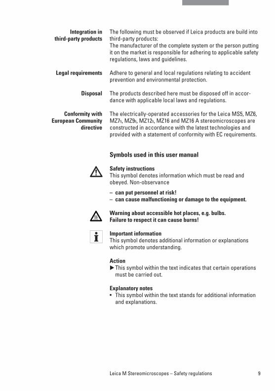
Symbols used in this user manual
Safety instructionsThis symbol denotes information which must be read andobeyed. Non-observance
– can put personnel at risk!– can cause malfunctioning or damage to the equipment.
Warning about accessible hot places, e.g. bulbs.Failure to respect it can cause burns!
Important informationThis symbol denotes additional information or explanations which promote understanding.
Action�This symbol within the text indicates that certain operations
must be carried out.
Explanatory notes• This symbol within the text stands for additional information
and explanations.
Integration in third-party products
Legal requirements
Disposal
Conformity with European Community
directive
9Leica M Stereomicroscopes – Safety regulations
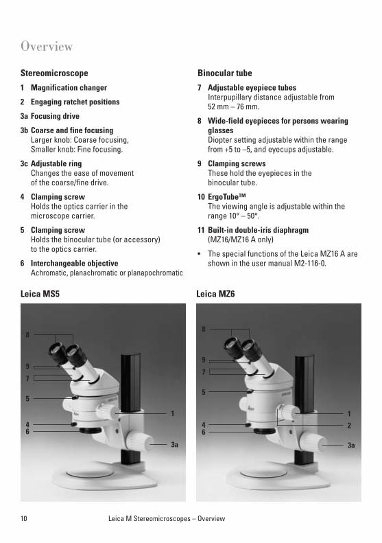
Stereomicroscope
1 Magnification changer
2 Engaging ratchet positions
3a Focusing drive
3b Coarse and fine focusingLarger knob: Coarse focusing, Smaller knob: Fine focusing.
3c Adjustable ringChanges the ease of movement of the coarse/fine drive.
4 Clamping screwHolds the optics carrier in the microscope carrier.
5 Clamping screwHolds the binocular tube (or accessory) to the optics carrier.
6 Interchangeable objectiveAchromatic, planachromatic or planapochromatic
Binocular tube
7 Adjustable eyepiece tubesInterpupillary distance adjustable from 52 mm – 76 mm.
8 Wide-field eyepieces for persons wearingglasses Diopter setting adjustable within the rangefrom +5 to –5, and eyecups adjustable.
9 Clamping screwsThese hold the eyepieces in the binocular tube.
10 ErgoTube™ The viewing angle is adjustable within therange 10° – 50°.
11 Built-in double-iris diaphragm(MZ16/MZ16 A only)
• The special functions of the Leica MZ16 A areshown in the user manual M2-116-0.
10 Leica M Stereomicroscopes – Overview
Overview
Leica MS5
9
7
5
46
1
3a
8
Leica MZ6
9
7
5
46
1
2
3a
8
11Leica M Stereomicroscopes – Overview
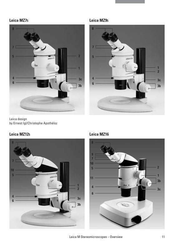
Leica designby Ernest Igl/Christophe Apothéloz
Leica MZ95
7
5
46
21
3c
3b
8
Leica MZ75
7
5
46
2
1
3c
3b
8
Leica MZ125
7
510
46
21
3c
3b
8
Leica MZ16
7
510
11
4
6
9
1
2
3b
3c
8
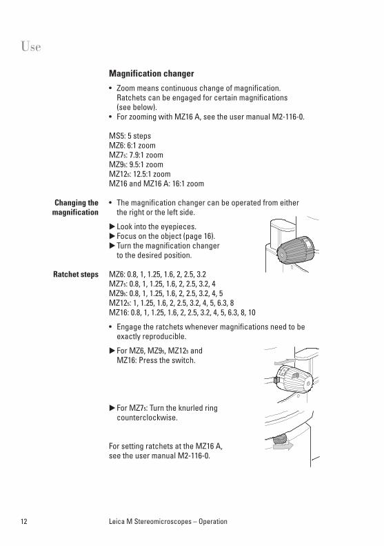
Magnification changer
• Zoom means continuous change of magnification. Ratchets can be engaged for certain magnifications (see below).
• For zooming with MZ16 A, see the user manual M2-116-0.
MS5: 5 stepsMZ6: 6:1 zoomMZ75: 7.9:1 zoomMZ95: 9.5:1 zoomMZ125: 12.5:1 zoomMZ16 and MZ16 A: 16:1 zoom
• The magnification changer can be operated from either the right or the left side.
�Look into the eyepieces.�Focus on the object (page 16).�Turn the magnification changer
to the desired position.
MZ6: 0.8, 1, 1.25, 1.6, 2, 2.5, 3.2MZ75: 0.8, 1, 1.25, 1.6, 2, 2.5, 3.2, 4 MZ95: 0.8, 1, 1.25, 1.6, 2, 2.5, 3.2, 4, 5MZ125: 1, 1.25, 1.6, 2, 2.5, 3.2, 4, 5, 6.3, 8MZ16: 0.8, 1, 1.25, 1.6, 2, 2.5, 3.2, 4, 5, 6.3, 8, 10
• Engage the ratchets whenever magnifications need to beexactly reproducible.
�For MZ6, MZ95, MZ125 and MZ16: Press the switch.
�For MZ75: Turn the knurled ring counterclockwise.
For setting ratchets at the MZ16 A, see the user manual M2-116-0.
Changing the magnification
Ratchet steps
12 Leica M Stereomicroscopes – Operation
Use
MS5, MZ6: Display of magnification factors from 0.63–4.
MZ75: Display of magnification factors from 0.63–5. Corresponding scales for other objective and eyepiece combi-nations can be affixed to the rotary knobs (page 34).
MZ95: Display of magnification factors from 0.63–6.
MZ125: Display of magnification factors from 0.8–10.
MZ16, MZ16 A: Display of magnification factors from 0.71–11.5
MZ16 A: For the digital display of the magnification see the usermanual M2-116-0.
The tables on pages 62 – 66 provide information about the magnifications and field of view diameters as a function of themagnification changer position of the eyepiece-objective combination used.
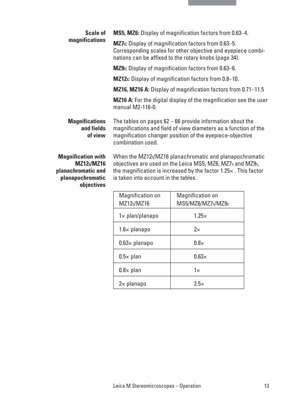
When the MZ125/MZ16 planachromatic and planapochromaticobjectives are used on the Leica MS5, MZ6, MZ75 and MZ95, the magnification is increased by the factor 1.25× . This factoris taken into account in the tables.
Scale of magnifications
Magnifications and fields
of view
Magnification withMZ125/MZ16
planachromatic andplanapochromatic
objectives
13Leica M Stereomicroscopes – Operation
Magnification on Magnification on MZ125/MZ16 MS5/MZ6/MZ75/MZ95
1× plan/planapo 1.25×
1.6× planapo 2×
0.63× planapo 0.8×
0.5× plan 0.63×
0.8× plan 1×
2× planapo 2.5×
14 Leica M Stereomicroscopes – Operation
Ergonomics, viewing height
• Pay great attention when setting up your stereomicroscope.You will only benefit fully from the outstanding optical andergonomic advantages of the instrument if you set it up precisely in accordance with the directions already given.
• For fatigue-free work, use the ErgoModules™.• Arrange your workplace as well as possible, and pay
attention to the heights of chair and table.• When sitting, use the entire seat area and also the back
support of the chair.• Support your forearms.• During work breaks, stand up and move around for exercise.
Please also observe the note on p. 7.
The reasons why users often cannot work comfortably withthe 45° tube are the differing heights of the outfits, the variousaccessories and working distances, and the fact that thesame instrument is often used by several people of differingbuilds. This problem can be effectively solved by using theLeica ErgoModules™.If you have problems with the viewing configuration on yourstereomicroscope, ask your Leica consultant for the most ergonomic Leica solutions.
With the achromatic Ergo objective 0.4×– 0.63× for the LeicaMS5, MZ6, MZ75 and MZ95 it is possible to focus in the region of 90mm (63.5 mm – 153.5 mm) ergonomically and precisely,without changing the viewing height. At the same time, magnification and working distance can be changed withoutany time-consuming changing of the objectives.
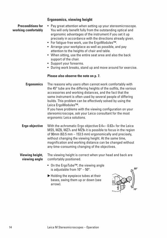
The viewing height is correct when your head and back arecomfortably positioned.
• On the ErgoTube™, the viewing angle is adjustable from 10° – 50°.
�Holding the eyepiece tubes at theirbases, swing them up or down (seearrow).
Preconditions forworking comfortably
Ergonomics
Ergo objective
Viewing height, viewing angle
– ErgoWedge™ 5° – 25°– ErgoWedge™ ±15°– ErgoModule™ 50 mm – The ErgoTube™ 45° has eyepiece tubes which are 65 mm
longer than the standard ones. Magnification factor 1.6×.
MZ16 A: The magnification factor can be toggled on and offusing the OPT key.
– ErgoModule™ 30 – 120 mmRelubrication may be required after several years (please send the item to Leica Service).
The achromatic Ergo objective 0.4×–0.63× can be used toergonomically and accurately focus in the range of 90 mm(63.5–153.5 mm) without changing the viewing height. At thesame time, magnification and working distance can be changed without time-consuming change of objectives.
Frequently repeated fine-motor tasks, such as focusing byhand, can lead to muscle fatigue and hand problems. Using theLeica motor focusing system, every equipment can be movedup and down without applying force.
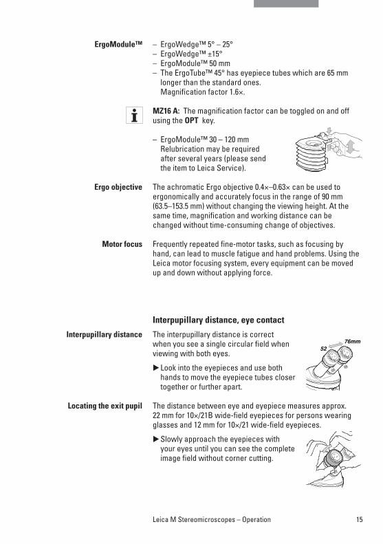
Interpupillary distance, eye contact
The interpupillary distance is correct when you see a single circular field whenviewing with both eyes.
�Look into the eyepieces and use bothhands to move the eyepiece tubes closertogether or further apart.
The distance between eye and eyepiece measures approx.22 mm for 10×/21B wide-field eyepieces for persons wearingglasses and 12 mm for 10×/21 wide-field eyepieces.
�Slowly approach the eyepieces with your eyes until you can see the completeimage field without corner cutting.
ErgoModule™
Ergo objective
Motor focus
Interpupillary distance
Locating the exit pupil
15Leica M Stereomicroscopes – Operation
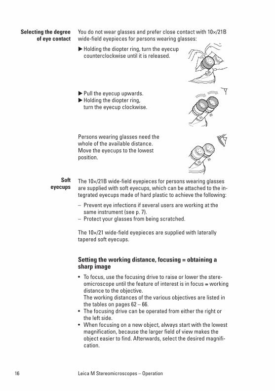
You do not wear glasses and prefer close contact with 10×/21Bwide-field eyepieces for persons wearing glasses:
�Holding the diopter ring, turn the eyecupcounterclockwise until it is released.
�Pull the eyecup upwards.�Holding the diopter ring,
turn the eyecup clockwise.
Persons wearing glasses need the whole of the available distance. Move the eyecups to the lowest position.
The 10×/21B wide-field eyepieces for persons wearing glassesare supplied with soft eyecups, which can be attached to the in-tegrated eyecups made of hard plastic to achieve the following:
– Prevent eye infections if several users are working at thesame instrument (see p. 7).
– Protect your glasses from being scratched.
The 10×/21 wide-field eyepieces are supplied with laterallytapered soft eyecups.
Setting the working distance, focusing = obtaining asharp image
• To focus, use the focusing drive to raise or lower the stere-omicroscope until the feature of interest is in focus ≅ workingdistance to the objective. The working distances of the various objectives are listed inthe tables on pages 62 – 66.
• The focusing drive can be operated from either the right orthe left side.
• When focusing on a new object, always start with the lowestmagnification, because the larger field of view makes theobject easier to find. Afterwards, select the desired magnifi-cation.
Selecting the degree of eye contact
Softeyecups
16 Leica M Stereomicroscopes – Operation
17Leica M Stereomicroscopes – Operation
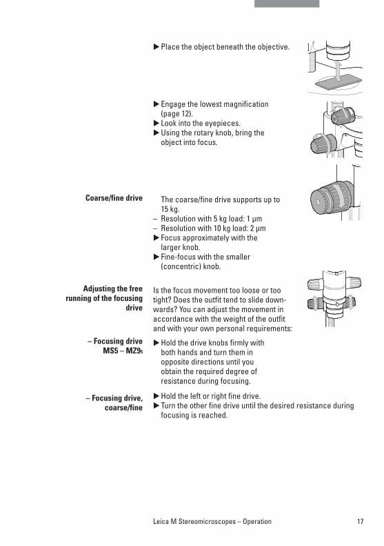
�Place the object beneath the objective.
�Engage the lowest magnification (page 12).
�Look into the eyepieces.�Using the rotary knob, bring the
object into focus.
The coarse/fine drive supports up to15 kg.
– Resolution with 5 kg load: 1 µm – Resolution with 10 kg load: 2 µm�Focus approximately with the
larger knob.�Fine-focus with the smaller
(concentric) knob.
Is the focus movement too loose or tootight? Does the outfit tend to slide down-wards? You can adjust the movement inaccordance with the weight of the outfitand with your own personal requirements:
�Hold the drive knobs firmly with both hands and turn them in opposite directions until you obtain the required degree of resistance during focusing.
�Hold the left or right fine drive.�Turn the other fine drive until the desired resistance during
focusing is reached.
Coarse/fine drive
Adjusting the free running of the focusing
drive
– Focusing driveMS5 – MZ95
– Focusing drive,coarse/fine
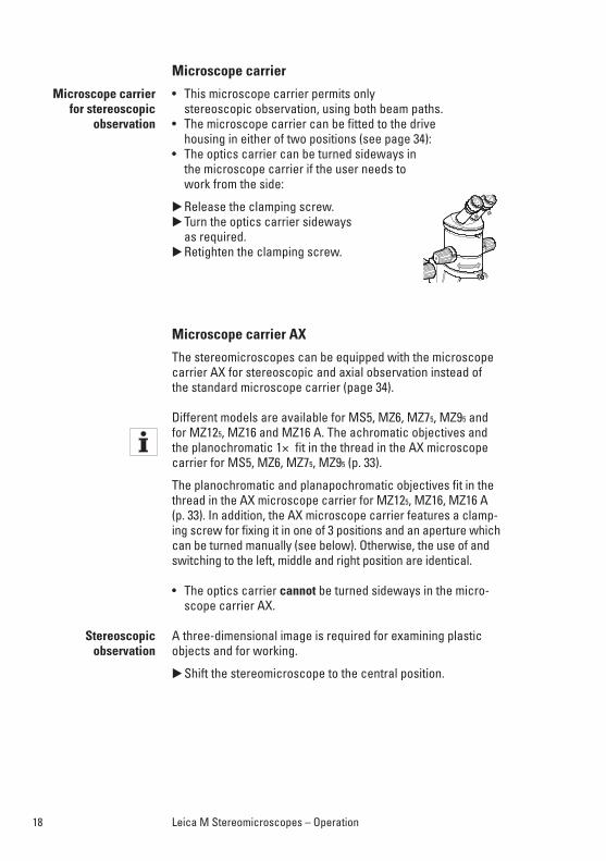
Microscope carrier
• This microscope carrier permits only stereoscopic observation, using both beam paths.
• The microscope carrier can be fitted to the drive housing in either of two positions (see page 34):
• The optics carrier can be turned sideways in the microscope carrier if the user needs to work from the side:
�Release the clamping screw.�Turn the optics carrier sideways
as required.�Retighten the clamping screw.
Microscope carrier AX
The stereomicroscopes can be equipped with the microscopecarrier AX for stereoscopic and axial observation instead of the standard microscope carrier (page 34).
Different models are available for MS5, MZ6, MZ75, MZ95 andfor MZ125, MZ16 and MZ16 A. The achromatic objectives andthe planochromatic 1× fit in the thread in the AX microscopecarrier for MS5, MZ6, MZ75, MZ95 (p. 33).
The planochromatic and planapochromatic objectives fit in thethread in the AX microscope carrier for MZ125, MZ16, MZ16 A (p. 33). In addition, the AX microscope carrier features a clamp-ing screw for fixing it in one of 3 positions and an aperture whichcan be turned manually (see below). Otherwise, the use of andswitching to the left, middle and right position are identical.
• The optics carrier cannot be turned sideways in the micro-scope carrier AX.
A three-dimensional image is required for examining plasticobjects and for working.
�Shift the stereomicroscope to the central position.
Microscope carrier for stereoscopic
observation
Stereoscopic observation
18 Leica M Stereomicroscopes – Operation
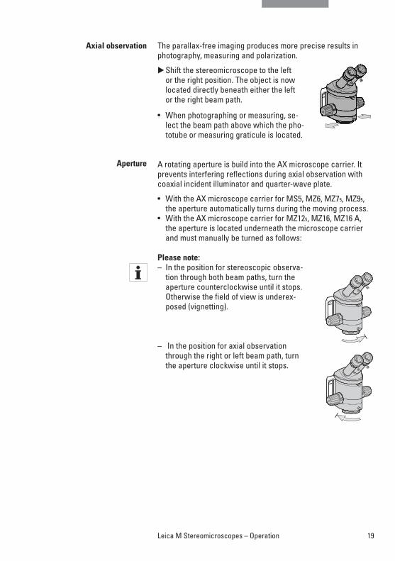
The parallax-free imaging produces more precise results inphotography, measuring and polarization.
�Shift the stereomicroscope to the left or the right position. The object is now located directly beneath either the left or the right beam path.
• When photographing or measuring, se-lect the beam path above which the pho-totube or measuring graticule is located.
A rotating aperture is build into the AX microscope carrier. Itprevents interfering reflections during axial observation withcoaxial incident illuminator and quarter-wave plate.
• With the AX microscope carrier for MS5, MZ6, MZ75, MZ95,the aperture automatically turns during the moving process.
• With the AX microscope carrier for MZ125, MZ16, MZ16 A,the aperture is located underneath the microscope carrierand must manually be turned as follows:
Please note:– In the position for stereoscopic observa-
tion through both beam paths, turn theaperture counterclockwise until it stops.Otherwise the field of view is underex-posed (vignetting).
– In the position for axial observationthrough the right or left beam path, turnthe aperture clockwise until it stops.
Axial observation
Aperture
19Leica M Stereomicroscopes – Operation
20 Leica M Stereomicroscopes – Operation
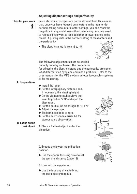
Adjusting diopter settings and parfocality
Leica stereomicroscopes are parfocally matched. This meansthat, once you have focused on a feature in the manner de-scribed, taking account of diopter settings, you can zoom themagnification up and down without refocusing. You only needto refocus if you want to look at higher or lower planes in theobject. A prerequisite is the correct setting of the diopters andthe parfocality.
• The dioptric range is from +5 to –5.
The following adjustments must be carriedout only once by each user. The proceduresfor adjusting the dioptric setting and the parfocality are some-what different if an eyepiece contains a graticule. Refer to theuser manuals for the MPS modular photomicrographic systemsor for measuring.
� Install the lamp.�Set the interpupillary distance and,
if necessary, the viewing height.�On the video/phototube: Move the
lever to position "VIS" and open thediaphragm.
�Set the double-iris diaphragm to "OPEN."�Adjust the eyecups.�Set both eyepieces to zero.�Set the microscope carrier AX for
stereoscopic observation.
1. Place a flat test object under theobjective.
2. Engage the lowest magnificationposition.
�Use the coarse focusing drive to set the working distance (page 16).
3. Look into the eyepieces
�Use the focusing drive, to bring the test object into focus.
Tips for your work
A Preparations
B Focus on the test object
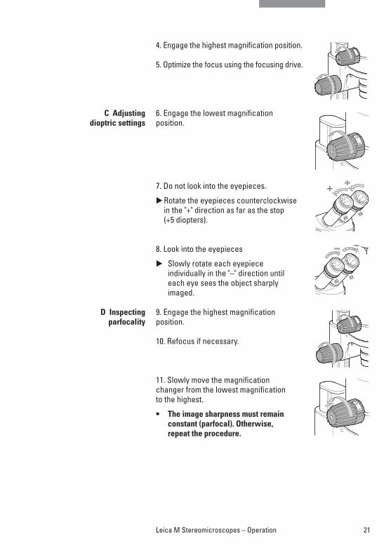
4. Engage the highest magnification position.
5. Optimize the focus using the focusing drive.
6. Engage the lowest magnificationposition.
7. Do not look into the eyepieces.
�Rotate the eyepieces counterclockwise in the "+" direction as far as the stop (+5 diopters).
8. Look into the eyepieces
� Slowly rotate each eyepiece individually in the "–" direction until each eye sees the object sharplyimaged.
9. Engage the highest magnificationposition.
10. Refocus if necessary.
11. Slowly move the magnification changer from the lowest magnification to the highest.
• The image sharpness must remain constant (parfocal). Otherwise, repeat the procedure.
C Adjusting dioptric settings
D Inspecting parfocality
21Leica M Stereomicroscopes – Operation
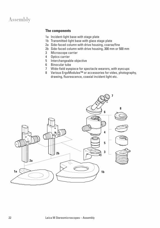
The components
1a Incident-light base with stage plate1b Transmitted-light base with glass stage plate2a Side-faced column with drive housing, coarse/fine2b Side-faced column with drive housing, 300 mm or 500 mm3 Microscope carrier4 Optics carrier5 Interchangeable objective6 Binocular tube 7 Wide-field eyepiece for spectacle wearers, with eyecups8 Various ErgoModules™ or accessories for video, photography,
drawing, fluorescence, coaxial incident light etc.
22 Leica M Stereomicroscopes – Assembly
Assembly
1a
2a
2b
1b
7
6
4
5
3
8
23Leica M Stereomicroscopes – Assembly
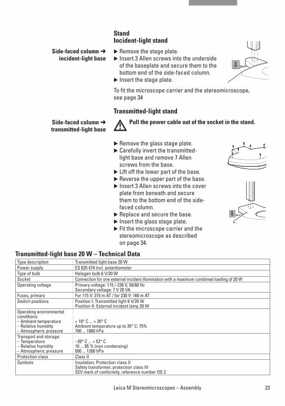
StandIncident-light stand
� Remove the stage plate.� Insert 3 Allen screws into the underside
of the baseplate and secure them to thebottom end of the side-faced column.
� Insert the stage plate.
To fit the microscope carrier and the stereomicroscope, see page 34
Transmitted-light stand
Pull the power cable out of the socket in the stand.
� Remove the glass stage plate.� Carefully invert the transmitted-
light base and remove 7 Allen screws from the base.
� Lift off the lower part of the base.� Reverse the upper part of the base.� Insert 3 Allen screws into the cover
plate from beneath and secure them to the bottom end of the side-faced column.
� Replace and secure the base.� Insert the glass stage plate.� Fit the microscope carrier and the
stereomicroscope as described on page 34.
Side-faced column ➜ incident-light base
Side-faced column ➜ transmitted-light base
Type description Transmitted light base 20 WPower supply ES 635 474 incl. potentiometerType of bulb Halogen bulb 6 V/20 W Socket Connection for one external incident illumination with a maximum combined loading of 20 WOperating voltage Primary voltage: 115 /-230 V, 50/60 Hz
Secondary voltage: 7 V 28 VAFuses, primary For 115 V: 315 m AT / for 230 V: 160 m ATSwitch positions Position I: Transmitted light 6 V/20 W
Position II: External incident lamp 20 WOperating environmentalconditions:– Ambient temperature + 10° C ... + 35° C– Relative humidity Ambient temperature up to 35° C: 75% – Atmospheric pressure 700 ... 1060 hPaTransport and storage:– Temperature –20° C ... + 52° C– Relative humidity 10 ... 95 % (non condensing)– Atmospheric pressure 500 ... 1200 hPaProtection class Class IISymbols Insulation, Protection class II
Safety transformer, protection class IIISEV mark of conformity, reference number OG 2
Transmitted-light base 20 W – Technical Data
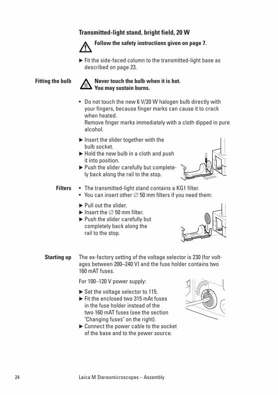
Transmitted-light stand, bright field, 20 W
Follow the safety instructions given on page 7.
� Fit the side-faced column to the transmitted-light base asdescribed on page 23.
Never touch the bulb when it is hot. You may sustain burns.
• Do not touch the new 6 V/20 W halogen bulb directly withyour fingers, because finger marks can cause it to crackwhen heated. Remove finger marks immediately with a cloth dipped in purealcohol.
� Insert the slider together with the bulb socket.
� Hold the new bulb in a cloth and pushit into position.
� Push the slider carefully but complete-ly back along the rail to the stop.
• The transmitted-light stand contains a KG1 filter.• You can insert other ∅ 50 mm filters if you need them:
� Pull out the slider.� Insert the ∅ 50 mm filter.� Push the slider carefully but
completely back along the rail to the stop.
The ex-factory setting of the voltage selector is 230 (for volt-ages between 200–240 V) and the fuse holder contains two160 mAT fuses.
For 100–120 V power supply:
� Set the voltage selector to 115.� Fit the enclosed two 315 mAt fuses
in the fuse holder instead of thetwo 160 mAT fuses (see the section"Changing fuses" on the right).
� Connect the power cable to the socket of the base and to the power source.
Fitting the bulb
Filters
Starting up
24 Leica M Stereomicroscopes – Assembly
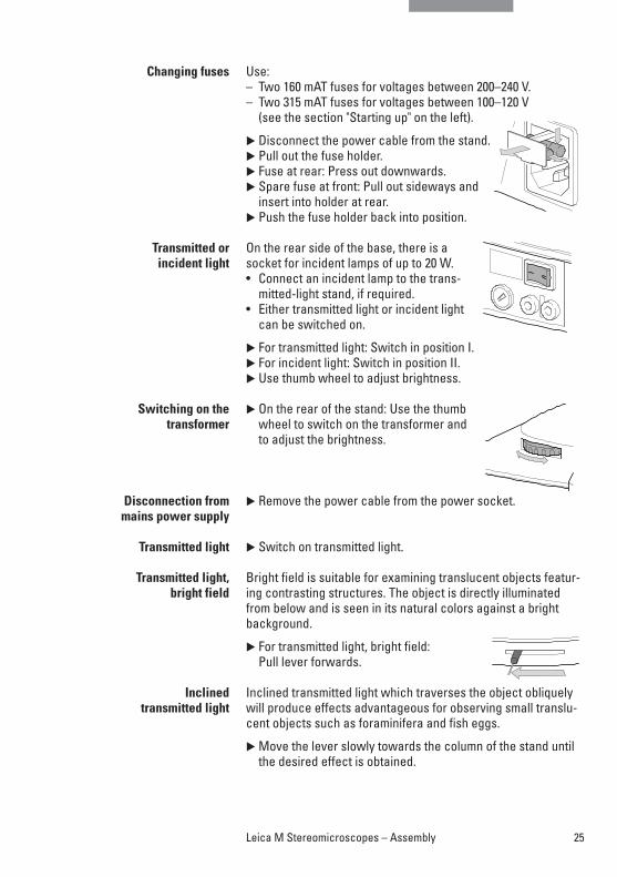
Use:– Two 160 mAT fuses for voltages between 200–240 V.– Two 315 mAT fuses for voltages between 100–120 V
(see the section "Starting up" on the left).
� Disconnect the power cable from the stand.� Pull out the fuse holder. � Fuse at rear: Press out downwards. � Spare fuse at front: Pull out sideways and
insert into holder at rear.� Push the fuse holder back into position.
On the rear side of the base, there is asocket for incident lamps of up to 20 W.• Connect an incident lamp to the trans-
mitted-light stand, if required.• Either transmitted light or incident light
can be switched on.
� For transmitted light: Switch in position I. � For incident light: Switch in position II.� Use thumb wheel to adjust brightness.
� On the rear of the stand: Use the thumbwheel to switch on the transformer andto adjust the brightness.
� Remove the power cable from the power socket.
� Switch on transmitted light.
Bright field is suitable for examining translucent objects featur-ing contrasting structures. The object is directly illuminatedfrom below and is seen in its natural colors against a brightbackground.
� For transmitted light, bright field: Pull lever forwards.
Inclined transmitted light which traverses the object obliquelywill produce effects advantageous for observing small translu-cent objects such as foraminifera and fish eggs.
� Move the lever slowly towards the column of the stand untilthe desired effect is obtained.
Changing fuses
Transmitted or incident light
Switching on thetransformer
Disconnection frommains power supply
Transmitted light
Transmitted light,bright field
Inclined transmitted light
25Leica M Stereomicroscopes – Assembly
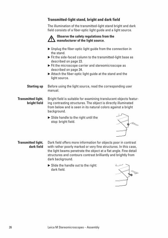
Transmitted-light stand, bright and dark field
The illumination of the transmitted-light stand bright and darkfield consists of a fiber-optic light guide and a light source.
Observe the safety regulations from the manufacturer of the light source.
� Unplug the fiber-optic light guide from the connection in the stand.
� Fit the side-faced column to the transmitted-light base asdescribed on page 23.
� Fit the microscope carrier and stereomicroscope as described on page 34.
� Attach the fiber-optic light guide at the stand and the light source.
Before using the light source, read the corresponding usermanual.
Bright field is suitable for examining translucent objects featur-ing contrasting structures. The object is directly illuminatedfrom below and is seen in its natural colors against a brightbackground.
� Slide handle to the right until the stop: bright field.
Dark field offers more information for objects poor in contrastwith rather poorly marked or very fine structures. In this case,the light beams penetrate the object at a flat angle. Fine detailstructures and contours contrast brilliantly and brightly fromdark background.
� Slide the handle out to the right: dark field.
Starting up
Transmitted light,bright field
Transmitted light, dark field
26 Leica M Stereomicroscopes – Assembly
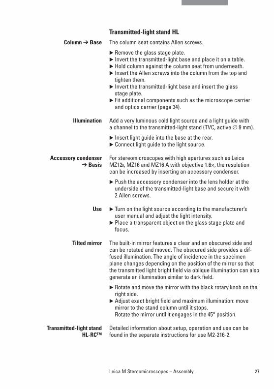
Transmitted-light stand HL
The column seat contains Allen screws.
� Remove the glass stage plate.� Invert the transmitted-light base and place it on a table.� Hold column against the column seat from underneath. � Insert the Allen screws into the column from the top and
tighten them.� Invert the transmitted-light base and insert the glass
stage plate.� Fit additional components such as the microscope carrier
and optics carrier (page 34).
Add a very luminous cold light source and a light guide with a channel to the transmitted-light stand (TVC, active ∅ 9 mm).
� Insert light guide into the base at the rear.� Connect light guide to the light source.
For stereomicroscopes with high apertures such as LeicaMZ125, MZ16 and MZ16 A with objective 1.6×, the resolutioncan be increased by inserting an accessory condenser.
� Push the accessory condenser into the lens holder at theunderside of the transmitted-light base and secure it with2 Allen screws.
� Turn on the light source according to the manufacturer’suser manual and adjust the light intensity.
� Place a transparent object on the glass stage plate andfocus.
The built-in mirror features a clear and an obscured side andcan be rotated and moved. The obscured side provides a dif-fused illumination. The angle of incidence in the specimenplane changes depending on the position of the mirror so thatthe transmitted light bright field via oblique illumination can alsogenerate an illumination similar to dark field.
� Rotate and move the mirror with the black rotary knob on theright side.
� Adjust exact bright field and maximum illumination: move mirror to the stand column until it stops. Rotate the mirror until it engages in the 45° position.
Detailed information about setup, operation and use can befound in the separate instructions for use M2-216-2.
Column ➔ Base
Illumination
Accessory condenser➔ Basis
Use
Tilted mirror
Transmitted-light stand HL-RC™
27Leica M Stereomicroscopes – Assembly
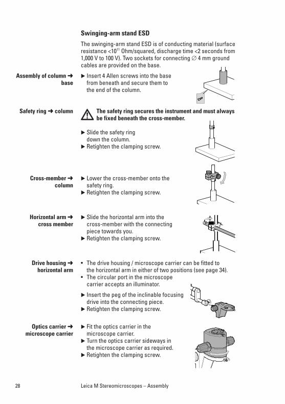
Swinging-arm stand ESD
The swinging-arm stand ESD is of conducting material (surfaceresistance <1011 Ohm/squared, discharge time <2 seconds from1,000 V to 100 V). Two sockets for connecting ∅ 4 mm groundcables are provided on the base.
� Insert 4 Allen screws into the base from beneath and secure them to the end of the column.
The safety ring secures the instrument and must alwaysbe fixed beneath the cross-member.
� Slide the safety ring down the column.
� Retighten the clamping screw.
� Lower the cross-member onto the safety ring.
� Retighten the clamping screw.
� Slide the horizontal arm into the cross-member with the connecting piece towards you.
� Retighten the clamping screw.
• The drive housing / microscope carrier can be fitted to the horizontal arm in either of two positions (see page 34).
• The circular port in the microscopecarrier accepts an illuminator.
� Insert the peg of the inclinable focusingdrive into the connecting piece.
� Retighten the clamping screw.
� Fit the optics carrier in the microscope carrier.
� Turn the optics carrier sideways in the microscope carrier as required.
� Retighten the clamping screw.
Assembly of column ➜base
Safety ring ➜ column
Cross-member ➜column
Horizontal arm ➜cross member
Drive housing ➜horizontal arm
Optics carrier ➜microscope carrier
28 Leica M Stereomicroscopes – Assembly
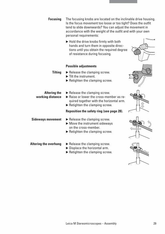
The focusing knobs are located on the inclinable drive housing.Is the focus movement too loose or too tight? Does the outfittend to slide downwards? You can adjust the movement in accordance with the weight of the outfit and with your own personal requirements:
� Hold the drive knobs firmly with bothhands and turn them in opposite direc-tions until you obtain the required degreeof resistance during focusing.
Possible adjustments
� Release the clamping screw. � Tilt the instrument.� Retighten the clamping screw.
� Release the clamping screw.� Raise or lower the cross-member as re-
quired together with the horizontal arm. � Retighten the clamping screw.
Reposition the safety ring (see page 28).
� Release the clamping screw.� Move the instrument sideways
on the cross-member. � Retighten the clamping screw.
� Release the clamping screw.� Displace the horizontal arm.� Retighten the clamping screw.
Focusing
Tilting
Altering the working distance
Sideways movement
Altering the overhang
29Leica M Stereomicroscopes – Assembly
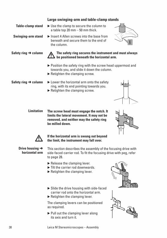
Large swinging-arm and table-clamp stands
� Use the clamp to secure the column toa table top 20 mm – 50 mm thick.
� Insert 4 Allen screws into the base frombeneath and secure them to the end ofthe column.
The safety ring secures the instrument and must alwaysbe positioned beneath the horizontal arm.
� Position the safety ring with the screw head uppermost andtowards you, and slide it down the column.
� Retighten the clamping screw.
� Lower the horizontal arm onto the safetyring, with its end pointing towards you.
� Retighten the clamping screw.
The screw head must engage the notch. Itlimits the lateral movement. It may not beremoved, and neither may the safety ring be milled down.
If the horizontal arm is swung out beyondthe limit, the instrument may fall over.
This section describes the assembly of the focusing drive withside-faced carrier rod. To fit the focusing drive with peg, referto page 28.
� Release the clamping lever.� Tilt the carrier rod downwards.� Retighten the clamping lever.
� Slide the drive housing with side-facedcarrier rod onto the horizontal arm.
� Retighten the clamping lever.
The clamping levers can be positionedas required.
� Pull out the clamping lever along its axis and turn it.
Table-clamp stand
Swinging-arm stand
Safety ring ➜ column
Safety ring ➜ column
Limitation
Drive housing ➜ horizontal arm
30 Leica M Stereomicroscopes – Assembly
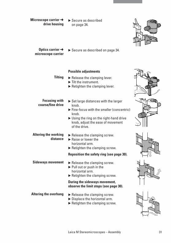
� Secure as described on page 34.
� Secure as described on page 34.
Possible adjustments
� Release the clamping lever. � Tilt the instrument.� Retighten the clamping lever.
� Set large distances with the larger knob.
� Fine-focus with the smaller (concentric)knob.
� Using the ring on the right-hand driveknob, adjust the ease of movement of the drive.
� Release the clamping screw.� Raise or lower the
horizontal arm. � Retighten the clamping screw.
Reposition the safety ring (see page 30).
� Release the clamping screw.� Pull out or push in the
horizontal arm. � Retighten the clamping screw.
During the sideways movement, observe the limit stops (see page 30).
� Release the clamping screw.� Displace the horizontal arm.� Retighten the clamping screw.
Microscope carrier ➜drive housing
Optics carrier ➜microscope carrier
Tilting
Focusing withcoarse/fine drive
Altering the workingdistance
Sideways movement
Altering the overhang
31Leica M Stereomicroscopes – Assembly
10 445 614 MZ6
10 411 589 1x10 422 562 1.5x10 447 081 2x10 473 832 0.8x10 445 201 0.63x10 422 563 0.5x10 422 564 0.32xAchromat
M1-
105-
MZ1
6 / 0
1.04
10 446 371 MZ75
10 446 272 MZ95
10 447 102 MZ16
10 447 103 MZ16 A
10 445 613 MS5
10 446 172
10 411 589 1x10 422 562 1.5x10 447 081 2x10 473 832 0.8x10 445 201 0.63x10 422 563 0.5x10 422 564 0.32xAchromat
10 446 275 1xPlan
10 446 275 1xPlan
10 445 819 1x Plan10 446 157 0.5x Plan10 447 075 0.8x Plan10 447 157 1x Planapo10 447 101 2x Planapo10 447 050 1.6x Planapo10 447 051 0.63x PlanapoPlan/Planapo
10 445 35210 315 306
10 367 929
10 445 35210 315 306
10 367 929
10 446 157 0.5x Plan10 447 075 0.8x Plan10 447 157 1x Planapo10 447 101 2x Planapo10 447 050 1.6x Planapo10 447 051 0.63x PlanapoPlan/Planapo
10 446 370 MZ125
10 447 148 0.4-0.63x Ergo
10 447 107
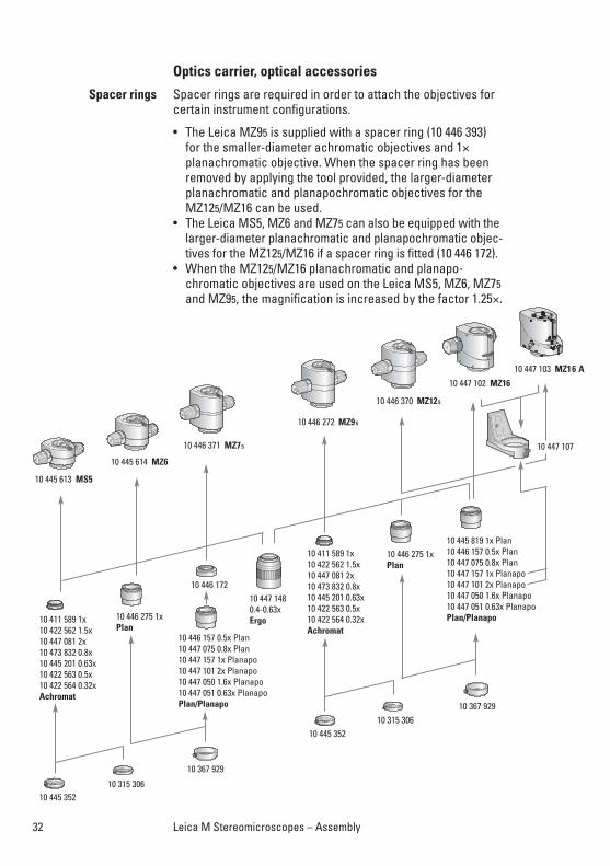
Spacer rings
32 Leica M Stereomicroscopes – Assembly
Optics carrier, optical accessories
Spacer rings are required in order to attach the objectives forcertain instrument configurations.
• The Leica MZ95 is supplied with a spacer ring (10 446 393)for the smaller-diameter achromatic objectives and 1×planachromatic objective. When the spacer ring has beenremoved by applying the tool provided, the larger-diameterplanachromatic and planapochromatic objectives for theMZ125/MZ16 can be used.
• The Leica MS5, MZ6 and MZ75 can also be equipped with thelarger-diameter planachromatic and planapochromatic objec-tives for the MZ125/MZ16 if a spacer ring is fitted (10 446 172).
• When the MZ125/MZ16 planachromatic and planapo-chromatic objectives are used on the Leica MS5, MZ6, MZ75and MZ95, the magnification is increased by the factor 1.25×.
33Leica M Stereomicroscopes User Manual
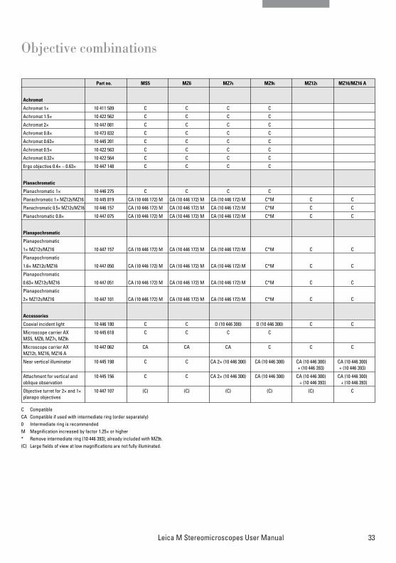
Objective combinations
C CompatibleCA Compatible if used with intermediate ring (order separately)0 Intermediate ring is recommendedM Magnification increased by factor 1.25× or higher* Remove intermediate ring (10 446 393); already included with MZ95.(C) Large fields of view at low magnifications are not fully illuminated.
Part no. MS5 MZ6 MZ75 MZ95 MZ125 MZ16/MZ16 A
Achromat
Achromat 1× 10 411 589 C C C C
Achromat 1.5× 10 422 562 C C C C
Achromat 2× 10 447 081 C C C C
Achromat 0.8× 10 473 832 C C C C
Achromat 0.63× 10 445 201 C C C C
Achromat 0.5× 10 422 563 C C C C
Achromat 0.32× 10 422 564 C C C C
Ergo objective 0.4× – 0.63× 10 447 148 C C C C
Planachromatic
Planachromatic 1× 10 446 275 C C C C
Planachromatic 1× MZ125/MZ16 10 445 819 CA (10 446 172) M CA (10 446 172) M CA (10 446 172) M C*M C C
Planachromatic 0.5× MZ125/MZ16 10 446 157 CA (10 446 172) M CA (10 446 172) M CA (10 446 172) M C*M C C
Planachromatic 0.8× 10 447 075 CA (10 446 172) M CA (10 446 172) M CA (10 446 172) M C*M C C
Planapochromatic
Planapochromatic
1× MZ125/MZ16 10 447 157 CA (10 446 172) M CA (10 446 172) M CA (10 446 172) M C*M C C
Planapochromatic
1.6× MZ125/MZ16 10 447 050 CA (10 446 172) M CA (10 446 172) M CA (10 446 172) M C*M C C
Planapochromatic
0.63× MZ125/MZ16 10 447 051 CA (10 446 172) M CA (10 446 172) M CA (10 446 172) M C*M C C
Planapochromatic
2× MZ125/MZ16 10 447 101 CA (10 446 172) M CA (10 446 172) M CA (10 446 172) M C*M C C
Accessories
Coaxial incident light 10 446 180 C C O (10 446 300) O (10 446 300) C C
Microscope carrier AX 10 445 618 C C C CMS5, MZ6, MZ75, MZ95
Microscope carrier AX 10 447 062 CA CA CA C C CMZ125, MZ16, MZ16 A
Near vertical illuminator 10 445 198 C C CA 2× (10 446 300) CA (10 446 300) CA (10 446 300) CA (10 446 300)+ (10 446 393) + (10 446 393)
Attachment for vertical and 10 445 156 C C CA 2× (10 446 300) CA (10 446 300) CA (10 446 300) CA (10 446 300)oblique observation + (10 446 393) + (10 446 393)
Objective turret for 2× and 1× 10 447 107 (C) (C) (C) (C) (C) Cplanapo objectives
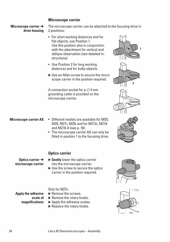
Microscope carrier
The microscope carrier can be attached to the focusing drive in2 positions:
• For short working distances and forflat objects, use Position 1.Use this position also in conjunction with the attachment for vertical andoblique observation (see detailed in-structions).
• Use Position 2 for long working distances and for bulky objects.
� Use an Allen screw to secure the micro-scope carrier in the position required.
A connection socket for a ∅ 4 mm grounding cable is provided on the microscope carrier.
• Different models are available for MS5,MZ6, MZ75, MZ95 and for MZ125, MZ16and MZ16 A (see p. 18).
• The microscope carrier AX can only befitted in position 1 to the focusing drive.
Optics carrier
� Gently lower the optics carrier into the microscope carrier.
� Use the screw to secure the optics carrier in the position required.
Only for MZ75:� Remove the screws.� Remove the rotary knobs.� Apply the adhesive scales.� Replace the rotary knobs.
34 Leica M Stereomicroscopes – Assembly
Microscope carrier ➜drive housing
Microscope carrier AX
Optics carrier ➜microscope carrier
Apply the adhesivescale of
magnifications
35Leica M Stereomicroscopes – Assembly
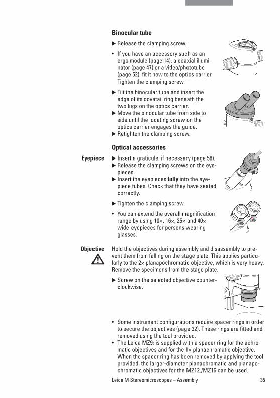
Binocular tube
� Release the clamping screw.
• If you have an accessory such as an ergo module (page 14), a coaxial illumi-nator (page 47) or a video/phototube (page 52), fit it now to the optics carrier.Tighten the clamping screw.
� Tilt the binocular tube and insert theedge of its dovetail ring beneath the two lugs on the optics carrier.
� Move the binocular tube from side toside until the locating screw on theoptics carrier engages the guide.
� Retighten the clamping screw.
Optical accessories
� Insert a graticule, if necessary (page 56).� Release the clamping screws on the eye-
pieces. � Insert the eyepieces fully into the eye-
piece tubes. Check that they have seatedcorrectly.
� Tighten the clamping screw.
• You can extend the overall magnificationrange by using 10×, 16×, 25× and 40×wide-eyepieces for persons wearingglasses.
Hold the objectives during assembly and disassembly to pre-vent them from falling on the stage plate. This applies particu-larly to the 2× planapochromatic objective, which is very heavy.Remove the specimens from the stage plate.
� Screw on the selected objective counter-clockwise.
• Some instrument configurations require spacer rings in orderto secure the objectives (page 32). These rings are fitted andremoved using the tool provided.
• The Leica MZ95 is supplied with a spacer ring for the achro-matic objectives and for the 1× planachromatic objective.When the spacer ring has been removed by applying the toolprovided, the larger-diameter planachromatic and planapo-chromatic objectives for the MZ125/MZ16 can be used.
Eyepiece
Objective
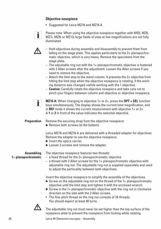
Objective nosepiece
• Suggested for Leica MZ16 and MZ16 A
Please note: When using the objective nosepiece together with MS5, MZ6,MZ75, MZ95 or MZ125 large fields of view at low magnifications are not fully illuminated.
– Hold objectives during assembly and disassembly to prevent them from falling on the stage plate. This applies particularly to the 2× planapochro-matic objective, which is very heavy. Remove the specimens from thestage plate.
– The adjustable ring nut with the 1× planapochromatic objective is fastenedwith 2 Allen screws after the adjustment. Loosen the Allen screws if youneed to remove the objective.
– Attach the limit stop to the stand column. It prevents the 2× objective fromhitting the limit stop when the objective nosepiece is rotating, if the work-ing distance was changed ×while working with the 1 objective.
– Caution: Carefully rotate the objective nosepiece and take care not topinch your fingers between column and objective or objective nosepiece.
MZ16 A: When changing to objective 1× or 2×, press the OPT + SEL functionkeys simultaneously. The display shows the current total magnification, andin REF mode it shows the current measurement with objective 1× or 2×. A 1 or 2 in front of the value indicates the selected objective.
Remove the securing strap from the objective nosepiece:� Remove both screws (at the bottom).
Leica MZ16 and MZ16 A are delivered with a threaded adapter for objectives.Remove the adapter to use the objective nosepiece.� Invert the optics carrier.� Loosen 3 screws and remove the adapter.
The objective nosepiece features two threads:– a fixed thread for the 2× planapochromatic objective – a thread with 2 Allen screws for the 1× planapochromatic objective with
adjustable ring nut. The adjustable ring nut is supplied separately and usedto adjust the parfocality between both objectives.
Invert the objective nosepiece to simplify the assembly of the objectives.� Screw on the adjustable ring nut on the thread of the 1× planapochromatic
objective until the limit stop and tighten it with the enclosed wrench.� Screw in the 1× planapochromatic objective with the ring nut in clockwise
direction on the side with the 2 Allen screws. • The fine-pitch thread on the ring nut consists of 24 threads.
You should expect at least 40 turns.
The adjustable ring nut must never be set higher than the top surface of thenosepiece plate to prevent the nosepiece from locking while rotating.
Preparation
Assembling1× planapochromatic
36 Leica M Stereomicroscopes – Assembly
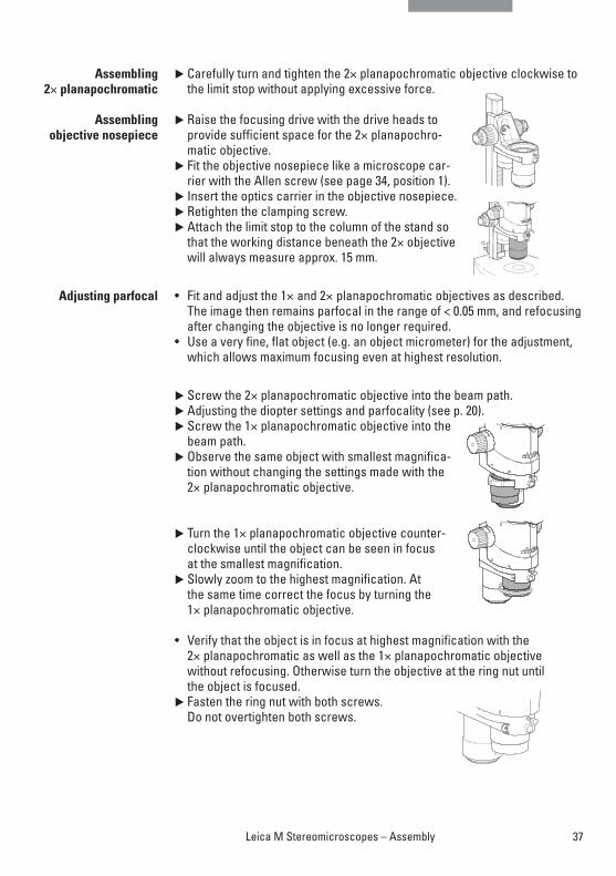
� Carefully turn and tighten the 2× planapochromatic objective clockwise tothe limit stop without applying excessive force.
� Raise the focusing drive with the drive heads toprovide sufficient space for the 2× planapochro-matic objective.
� Fit the objective nosepiece like a microscope car-rier with the Allen screw (see page 34, position 1).
� Insert the optics carrier in the objective nosepiece.� Retighten the clamping screw.� Attach the limit stop to the column of the stand so
that the working distance beneath the 2× objectivewill always measure approx. 15 mm.
• Fit and adjust the 1× and 2× planapochromatic objectives as described.The image then remains parfocal in the range of < 0.05 mm, and refocusingafter changing the objective is no longer required.
• Use a very fine, flat object (e.g. an object micrometer) for the adjustment,which allows maximum focusing even at highest resolution.
� Screw the 2× planapochromatic objective into the beam path.� Adjusting the diopter settings and parfocality (see p. 20).� Screw the 1× planapochromatic objective into the
beam path.� Observe the same object with smallest magnifica-
tion without changing the settings made with the2× planapochromatic objective.
� Turn the 1× planapochromatic objective counter-clockwise until the object can be seen in focus at the smallest magnification.
� Slowly zoom to the highest magnification. At the same time correct the focus by turning the 1× planapochromatic objective.
• Verify that the object is in focus at highest magnification with the 2× planapochromatic as well as the 1× planapochromatic objective without refocusing. Otherwise turn the objective at the ring nut until the object is focused.
� Fasten the ring nut with both screws.Do not overtighten both screws.
Assembling2× planapochromatic
Assembling objective nosepiece
Adjusting parfocal
37Leica M Stereomicroscopes – Assembly
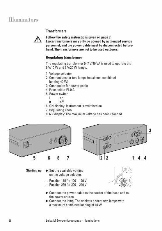
Transformers
Follow the safety instructions given on page 7.Leica transformers may only be opened by authorized servicepersonnel, and the power cable must be disconnected before-hand. The transformers are not to be used outdoors.
Regulating transformer
The regulating transformer 0–7 V/40 VA is used to operate the 6 V/10 W and 6 V/20 W lamps.
1 Voltage selector2 Connections for two lamps (maximum combined
loading 40 W)3 Connection for power cable4 Fuse holder F1.0 A5 Power switch
I on0 off
6 ON display: Instrument is switched on.7 Regulating knob8 6 V display: The maximum voltage has been reached.
� Set the available voltage on the voltage selector.
– Position 115 for 100 – 120 V– Position 230 for 200 – 240 V
� Connect the power cable to the socket of the base and to the power source.
� Connect the lamp. The sockets accept two lamps with a maximum combined loading of 40 W.
38 Leica M Stereomicroscopes – Illuminations
22 1 4 4
3
5 6 8 7
Starting up
Illuminators
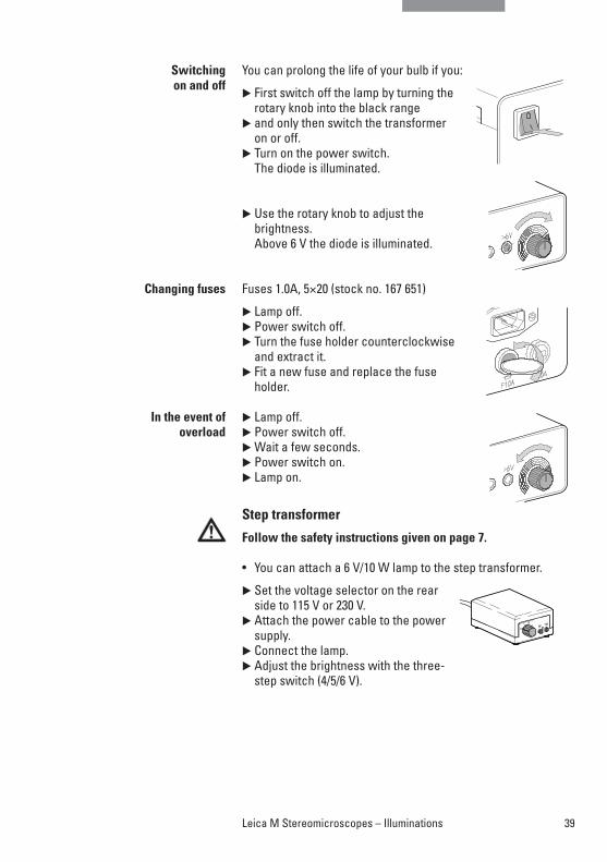
You can prolong the life of your bulb if you:
� First switch off the lamp by turning the rotary knob into the black range
� and only then switch the transformer on or off.
� Turn on the power switch. The diode is illuminated.
� Use the rotary knob to adjust the brightness. Above 6 V the diode is illuminated.
Fuses 1.0A, 5×20 (stock no. 167 651)
� Lamp off.� Power switch off.� Turn the fuse holder counterclockwise
and extract it. � Fit a new fuse and replace the fuse
holder.
� Lamp off.� Power switch off.� Wait a few seconds.� Power switch on.� Lamp on.
Step transformer
Follow the safety instructions given on page 7.
• You can attach a 6 V/10 W lamp to the step transformer.
� Set the voltage selector on the rearside to 115 V or 230 V.
� Attach the power cable to the powersupply.
� Connect the lamp.� Adjust the brightness with the three-
step switch (4/5/6 V).
Switching on and off
Changing fuses
In the event of overload
39Leica M Stereomicroscopes – Illuminations
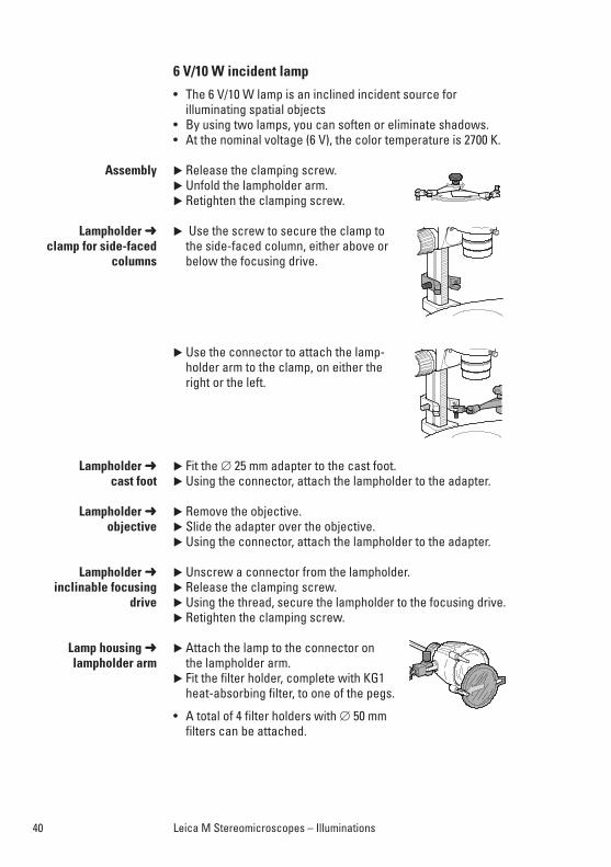
6 V/10 W incident lamp
• The 6 V/10 W lamp is an inclined incident source for illuminating spatial objects
• By using two lamps, you can soften or eliminate shadows.• At the nominal voltage (6 V), the color temperature is 2700 K.
� Release the clamping screw.� Unfold the lampholder arm.� Retighten the clamping screw.
� Use the screw to secure the clamp tothe side-faced column, either above orbelow the focusing drive.
� Use the connector to attach the lamp-holder arm to the clamp, on either theright or the left.
� Fit the ∅ 25 mm adapter to the cast foot.� Using the connector, attach the lampholder to the adapter.
� Remove the objective.� Slide the adapter over the objective.� Using the connector, attach the lampholder to the adapter.
� Unscrew a connector from the lampholder.� Release the clamping screw.� Using the thread, secure the lampholder to the focusing drive. � Retighten the clamping screw.
� Attach the lamp to the connector on the lampholder arm.
� Fit the filter holder, complete with KG1 heat-absorbing filter, to one of the pegs.
• A total of 4 filter holders with ∅ 50 mm filters can be attached.
Assembly
Lampholder ➜clamp for side-faced
columns
Lampholder ➜cast foot
Lampholder ➜objective
Lampholder ➜inclinable focusing
drive
Lamp housing ➜lampholder arm
40 Leica M Stereomicroscopes – Illuminations
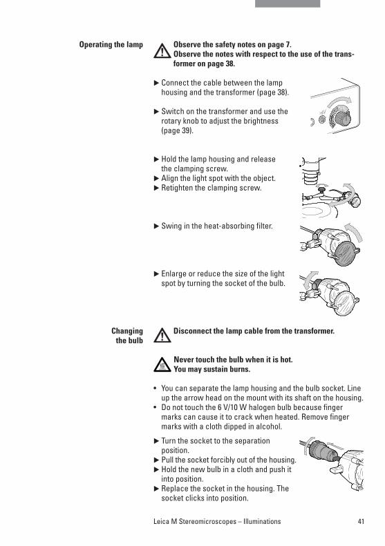
Observe the safety notes on page 7. Observe the notes with respect to the use of the trans-former on page 38.
� Connect the cable between the lamphousing and the transformer (page 38).
� Switch on the transformer and use therotary knob to adjust the brightness(page 39).
� Hold the lamp housing and release the clamping screw.
� Align the light spot with the object.� Retighten the clamping screw.
� Swing in the heat-absorbing filter.
� Enlarge or reduce the size of the lightspot by turning the socket of the bulb.
Disconnect the lamp cable from the transformer.
Never touch the bulb when it is hot. You may sustain burns.
• You can separate the lamp housing and the bulb socket. Lineup the arrow head on the mount with its shaft on the housing.
• Do not touch the 6 V/10 W halogen bulb because fingermarks can cause it to crack when heated. Remove fingermarks with a cloth dipped in alcohol.
� Turn the socket to the separation position.
� Pull the socket forcibly out of the housing.� Hold the new bulb in a cloth and push it
into position.� Replace the socket in the housing. The
socket clicks into position.
Operating the lamp
Changing the bulb
41Leica M Stereomicroscopes – Illuminations
42 Leica M Stereomicroscopes – Illuminations
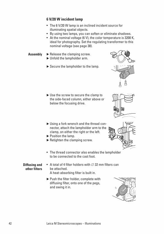
6 V/20 W incident lamp
• The 6 V/20 W lamp is an inclined incident source for illuminating spatial objects.
• By using two lamps, you can soften or eliminate shadows.• At the nominal voltage (6 V), the color temperature is 3200 K,
ideal for photography. Set the regulating transformer to thisnominal voltage (see page 38).
� Release the clamping screw.� Unfold the lampholder arm.
� Secure the lampholder to the lamp.
� Use the screw to secure the clamp to the side-faced column, either above orbelow the focusing drive.
� Using a fork wrench and the thread con-nector, attach the lampholder arm to theclamp, on either the right or the left.
� Position the lamp.� Retighten the clamping screw.
• The thread connector also enables the lampholder to be connected to the cast foot.
• A total of 4 filter holders with ∅ 32 mm filters can be attached. A heat-absorbing filter is built in.
� Push the filter holder, complete with diffusing filter, onto one of the pegs, and swing it in.
Assembly
Diffusing and other filters
43Leica M Stereomicroscopes – Illuminations
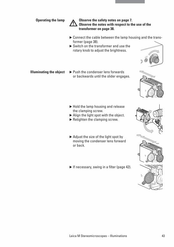
Observe the safety notes on page 7. Observe the notes with respect to the use of the transformer on page 38.
� Connect the cable between the lamp housing and the trans-former (page 38).
� Switch on the transformer and use therotary knob to adjust the brightness.
� Push the condenser lens forwards or backwards until the slider engages.
� Hold the lamp housing and release the clamping screw.
� Align the light spot with the object. � Retighten the clamping screw.
� Adjust the size of the light spot by moving the condenser lens forward or back.
� If necessary, swing in a filter (page 42).
Operating the lamp
Illuminating the object
44 Leica M Stereomicroscopes – Illuminations
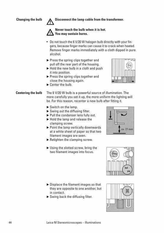
Disconnect the lamp cable from the transformer.
Never touch the bulb when it is hot. You may sustain burns.
• Do not touch the 6 V/20 W halogen bulb directly with your fin-gers, because finger marks can cause it to crack when heated.Remove finger marks immediately with a cloth dipped in purealcohol.
� Press the spring clips together and pull off the rear part of the housing.
� Hold the new bulb in a cloth and push it into position.
� Press the spring clips together and close the housing again.
� Center the bulb.
The 6 V/20 W bulb is a powerful source of illumination. Themore carefully you set it up, the more uniform the lighting willbe. For this reason, recenter a new bulb after fitting it.
� Switch on the lamp.� Swing out the diffusing filter.� Pull the condenser lens fully out.� Hold the lamp and release the
clamping screw. � Point the lamp vertically downwards
at a white sheet of paper so that twofilament images are seen.
� Retighten the clamping screw.
� Using the slotted screw, bring the two filament images into focus.
� Displace the filament images so thatthey are opposite to one another, but in contact.
� Swing back the diffusing filter.
Changing the bulb
Centering the bulb
45Leica M Stereomicroscopes – Illuminations
Leica L2 cold-light source
The antistatic Leica L2 cold-light source is powerful, small,compact, inexpensive and suitable for simple observation taskswith the Leica MS5 and MZ6 stereo microscopes. In addition toone or two-arm light guides, corresponding accessories are al-so available for the coaxial, vertical and transmitted-light illumi-nation methods. The Leica L2 can be directly connected on thestand.
The light guides can be mounted with arms in the threads onthe microscope carrier. For instructions on mounting the clampfor fiber-optic light guides, see page 46.
For detailed information, refer to the separate user manual Leica L2 M2-288-0.
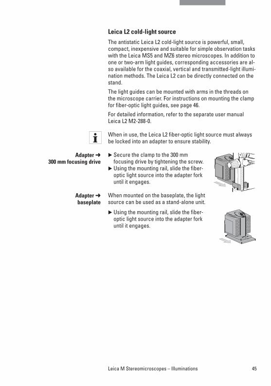
When in use, the Leica L2 fiber-optic light source must always be locked into an adapter to ensure stability.
� Secure the clamp to the 300 mm focusing drive by tightening the screw.
� Using the mounting rail, slide the fiber-optic light source into the adapter forkuntil it engages.
When mounted on the baseplate, the lightsource can be used as a stand-alone unit.
� Using the mounting rail, slide the fiber-optic light source into the adapter forkuntil it engages.
Adapter ➜300 mm focusing drive
Adapter ➜baseplate
46 Leica M Stereomicroscopes – Illuminations
Cold light source Leica CLS series
The Leica CLS series is a high-performance line for high lightintensity within the smallest possible space and flicker-freewhite light with the lowest possible thermal effect on the ob-jects. The comprehensive line of accessories enables unlimiteduse. The CLS series is produced of antistatic material.
When using the ring lamp (∅ 76 mm) on the planachromatic objective 0.8× (∅ 80 mm), a special adapter (10 447 078) is required.
For a detailed information, refer to the user manual Leica CLS.
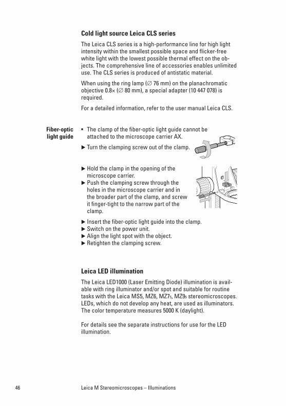
• The clamp of the fiber-optic light guide cannot be attached to the microscope carrier AX.
� Turn the clamping screw out of the clamp.
� Hold the clamp in the opening of the microscope carrier.
� Push the clamping screw through theholes in the microscope carrier and inthe broader part of the clamp, and screwit finger-tight to the narrow part of theclamp.
� Insert the fiber-optic light guide into the clamp.� Switch on the power unit.� Align the light spot with the object.� Retighten the clamping screw.
Leica LED illumination
The Leica LED1000 (Laser Emitting Diode) illumination is avail-able with ring illuminator and/or spot and suitable for routinetasks with the Leica MS5, MZ6, MZ75, MZ95 stereomicroscopes.LEDs, which do not develop any heat, are used as illuminators.The color temperature measures 5000 K (daylight).
For details see the separate instructions for use for the LED illumination.
Fiber-optic light guide
47Leica M Stereomicroscopes – Illuminations
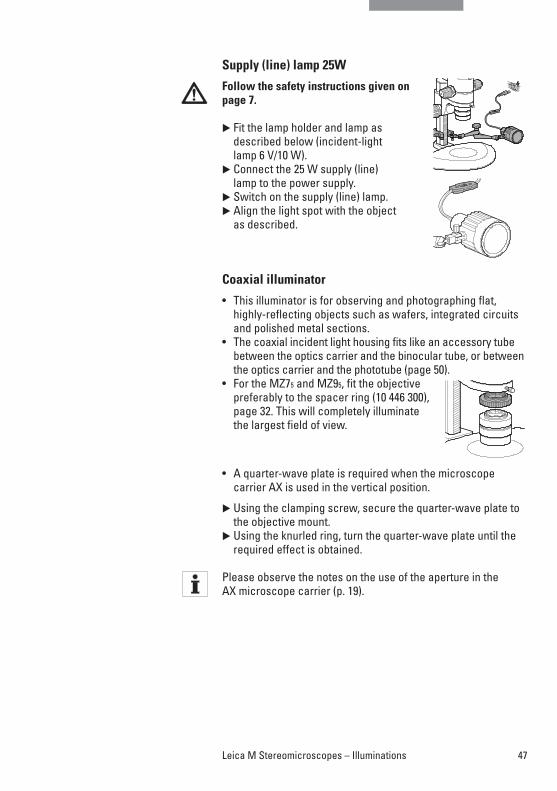
Supply (line) lamp 25W
Follow the safety instructions given onpage 7.
� Fit the lamp holder and lamp as described below (incident-light lamp 6 V/10 W).
� Connect the 25 W supply (line) lamp to the power supply.
� Switch on the supply (line) lamp.� Align the light spot with the object
as described.
Coaxial illuminator
• This illuminator is for observing and photographing flat, highly-reflecting objects such as wafers, integrated circuitsand polished metal sections.
• The coaxial incident light housing fits like an accessory tubebetween the optics carrier and the binocular tube, or betweenthe optics carrier and the phototube (page 50).
• For the MZ75 and MZ95, fit the objectivepreferably to the spacer ring (10 446 300),page 32. This will completely illuminatethe largest field of view.
• A quarter-wave plate is required when the microscope carrier AX is used in the vertical position.
� Using the clamping screw, secure the quarter-wave plate tothe objective mount.
� Using the knurled ring, turn the quarter-wave plate until therequired effect is obtained.
Please observe the notes on the use of the aperture in the AX microscope carrier (p. 19).
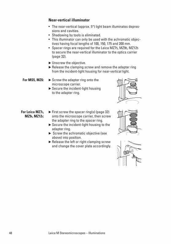
Near-vertical illuminator
• The near-vertical (approx. 5°) light beam illuminates depres-sions and cavities.
• Shadowing by tools is eliminated.• This illuminator can only be used with the achromatic objec-
tives having focal lengths of 100, 150, 175 and 200 mm.• Spacer rings are required for the Leica MZ75, MZ95, MZ125
to secure the near-vertical illuminator to the optics carrier(page 32).
� Unscrew the objective.� Release the clamping screw and remove the adapter ring
from the incident-light housing for near-vertical light.
� Screw the adapter ring onto the microscope carrier.
� Secure the incident-light housing to the adapter ring.
� First screw the spacer ring(s) (page 32) onto the microscope carrier, then screwthe adapter ring to the spacer ring.
� Secure the incident-light housing to theadapter ring.
� Screw the achromatic objective (seeabove) into position.
� Release the left or right clamping screwand change the cover plate accordingly.
For MS5, MZ6:
For Leica MZ75, MZ95, MZ125:
48 Leica M Stereomicroscopes – Illuminations
49Leica M Stereomicroscopes – Illuminations
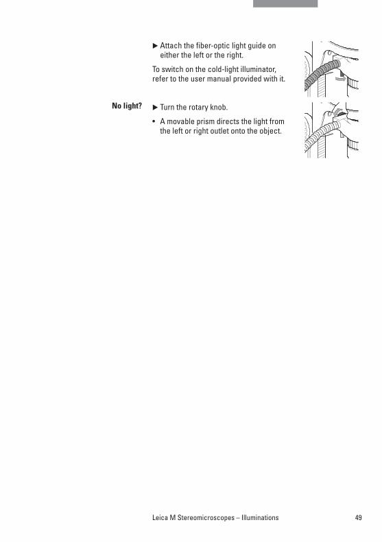
� Attach the fiber-optic light guide on either the left or the right.
To switch on the cold-light illuminator, refer to the user manual provided with it.
� Turn the rotary knob.
• A movable prism directs the light fromthe left or right outlet onto the object.
No light?
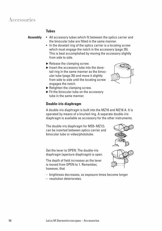
Tubes
• All accessory tubes which fit between the optics carrier andthe binocular tube are fitted in the same manner.
• In the dovetail ring of the optics carrier is a locating screwwhich must engage the notch in the accessory (page 35).This is best accomplished by moving the accessory slightlyfrom side to side.
� Release the clamping screw.� Insert the accessory tube into the dove-
tail ring in the same manner as the binoc-ular tube (page 35) and move it slightlyfrom side to side until the locating screwengages the notch.
� Retighten the clamping screw.� Fit the binocular tube on the accessory
tube in the same manner.
Double-iris diaphragm
A double-iris diaphragm is built into the MZ16 and MZ16 A. It isoperated by means of a knurled ring. A separate double-iris diaphragm is available as accessory for the other instruments.
The double-iris diaphragm for MS5–MZ125
can be inserted between optics carrier andbinocular tube or video/phototube.
Set the lever to OPEN: The double-iris diaphragm (aperture diaphragm) is open.
The depth of field increases as the lever is moved from OPEN to 1. Remember,however, that
– brightness decreases, so exposure times become longer– resolution deteriorates.
Assembly
50 Leica M Stereomicroscopes – Accessories
Accessories
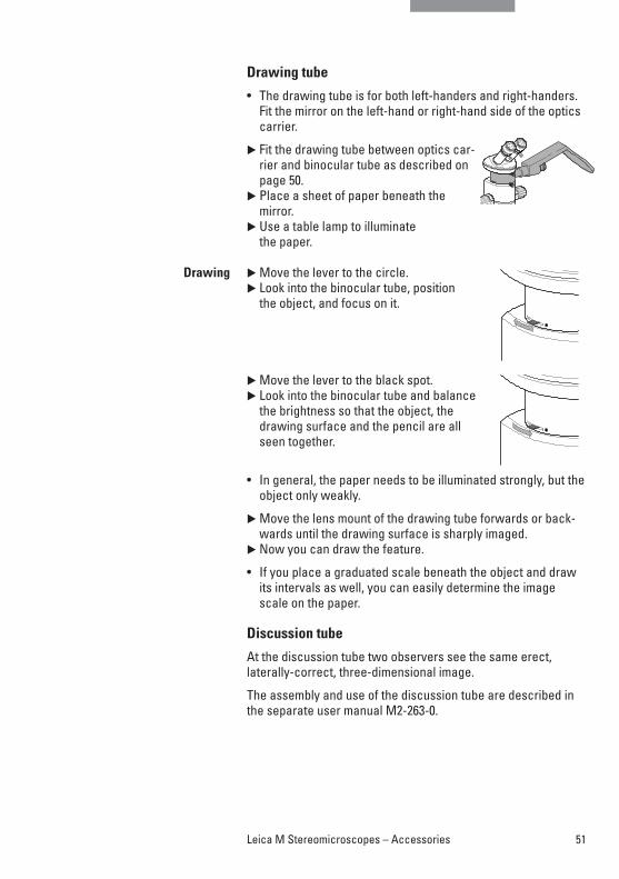
Drawing tube
• The drawing tube is for both left-handers and right-handers.Fit the mirror on the left-hand or right-hand side of the opticscarrier.
� Fit the drawing tube between optics car-rier and binocular tube as described onpage 50.
� Place a sheet of paper beneath themirror.
� Use a table lamp to illuminate the paper.
� Move the lever to the circle.� Look into the binocular tube, position
the object, and focus on it.
� Move the lever to the black spot.� Look into the binocular tube and balance
the brightness so that the object, thedrawing surface and the pencil are allseen together.
• In general, the paper needs to be illuminated strongly, but theobject only weakly.
� Move the lens mount of the drawing tube forwards or back-wards until the drawing surface is sharply imaged.
� Now you can draw the feature.
• If you place a graduated scale beneath the object and drawits intervals as well, you can easily determine the imagescale on the paper.
Discussion tube
At the discussion tube two observers see the same erect,laterally-correct, three-dimensional image.
The assembly and use of the discussion tube are described inthe separate user manual M2-263-0.
Drawing
51Leica M Stereomicroscopes – Accessories
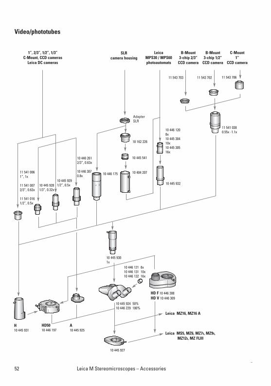
Video/phototubes
52 Leica M Stereomicroscopes – Accessories
LeicaMPS30 / MPS60photoautomats
10 445 927
10 445 924 50%10 446 229 100%
10 446 121 8x10 446 131 10x10 446 132 16x
11 541 0380.55x -1.1x
11 543 703 11 543 706
10 445 932
10 446 1208x10 445 30410x 10 445 30516x
10 404 207
10 445 541
10 162 226
AdapterSLR
SLRcamera housing
10 445 9291/2”, 0.5x10 445 928
1/3”, 0.32x
11 541 0061”, 1x
11 541 0072/3”, 0.63x
11 541 0161/2”, 0.5x
1”, 2/3”, 1/2”, 1/3”C-Mount, CCD cameras
Leica DC cameras
C-Mount1”
CCD camera
B-Mount3-chip 1/2”
CCD camera
B-Mount3-chip 2/3”
CCD camera
HD F 10 446 308HD V 10 446 309
HD5010 446 197
A10 445 925
H10 445 931
Leica MS5, MZ6, MZ75, MZ95, MZ125, MZ FLIII
11 543 702
10 445 9301x
10 446 175
4
10 446 2612/3”, 0.63x
10 446 3070.8x
Leica MZ16, MZ16 A
• Video/phototubes are designed to support modularphotomicrography systems, and Leica digital, video, film or SLR cameras.
• The modular photomicrographic systems and the Leica digi-tal cameras are detailed in a separate user manual, alongwith instructions for their assembly and use.
• When you are not taking photographs, engage the observa-tion beam path.
• Accessories such as the coaxial incident illuminator alwaysfit between the stereomicroscope and the phototube.
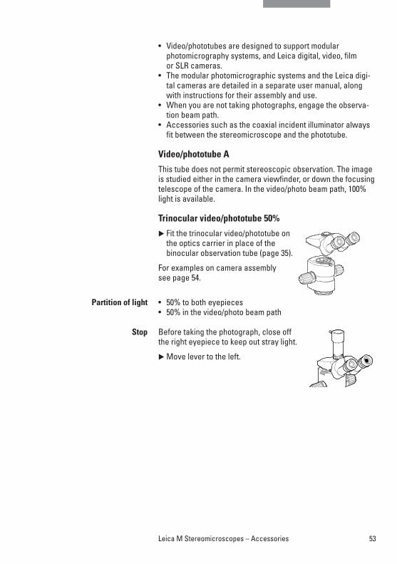
Video/phototube A
This tube does not permit stereoscopic observation. The imageis studied either in the camera viewfinder, or down the focusing telescope of the camera. In the video/photo beam path, 100%light is available.
Trinocular video/phototube 50%
� Fit the trinocular video/phototube onthe optics carrier in place of thebinocular observation tube (page 35).
For examples on camera assembly see page 54.
• 50% to both eyepieces• 50% in the video/photo beam path
Before taking the photograph, close off the right eyepiece to keep out stray light.
� Move lever to the left.
Partition of light
Stop
53Leica M Stereomicroscopes – Accessories
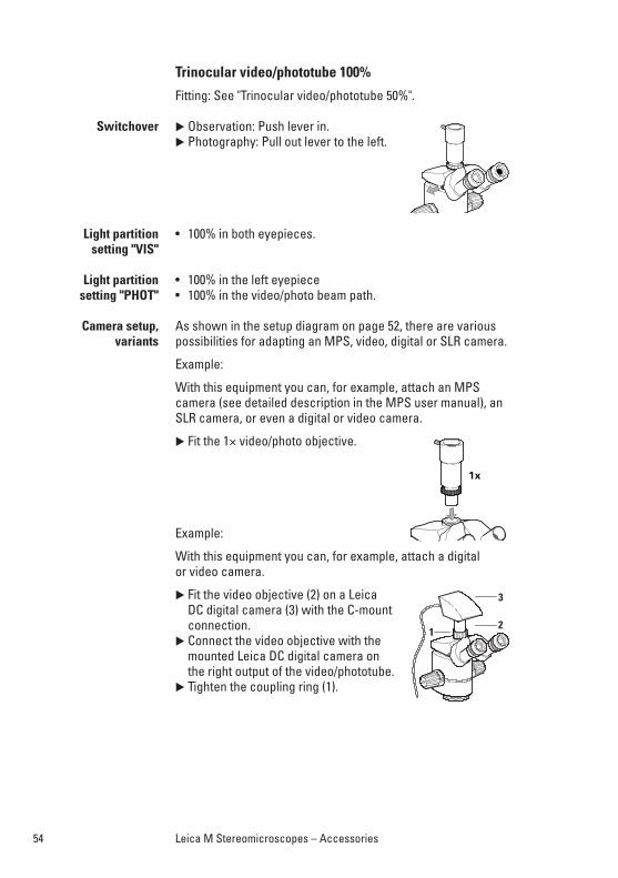
Trinocular video/phototube 100%
Fitting: See "Trinocular video/phototube 50%".
� Observation: Push lever in.� Photography: Pull out lever to the left.
• 100% in both eyepieces.
• 100% in the left eyepiece• 100% in the video/photo beam path.
As shown in the setup diagram on page 52, there are variouspossibilities for adapting an MPS, video, digital or SLR camera.
Example:
With this equipment you can, for example, attach an MPS camera (see detailed description in the MPS user manual), anSLR camera, or even a digital or video camera.
� Fit the 1× video/photo objective.
Example:
With this equipment you can, for example, attach a digital or video camera.
� Fit the video objective (2) on a Leica DC digital camera (3) with the C-mountconnection.
� Connect the video objective with themounted Leica DC digital camera on the right output of the video/phototube.
� Tighten the coupling ring (1).
Switchover
Light partition setting "VIS"
Light partition setting "PHOT"
Camera setup,variants
54 Leica M Stereomicroscopes – Accessories
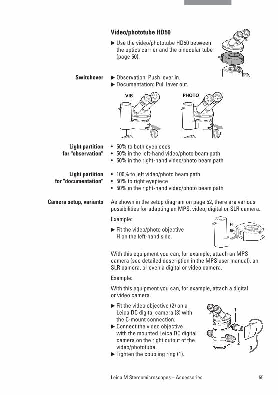
Video/phototube HD50
� Use the video/phototube HD50 between the optics carrier and the binocular tube(page 50).
� Observation: Push lever in.� Documentation: Pull lever out.
• 50% to both eyepieces• 50% in the left-hand video/photo beam path• 50% in the right-hand video/photo beam path
• 100% to left video/photo beam path• 50% to right eyepiece• 50% in the right-hand video/photo beam path
As shown in the setup diagram on page 52, there are variouspossibilities for adapting an MPS, video, digital or SLR camera.
Example:
� Fit the video/photo objective H on the left-hand side.
With this equipment you can, for example, attach an MPS camera (see detailed description in the MPS user manual), anSLR camera, or even a digital or video camera.
Example:
With this equipment you can, for example, attach a digital or video camera.
� Fit the video objective (2) on a Leica DC digital camera (3) with the C-mount connection.
� Connect the video objective with the mounted Leica DC digitalcamera on the right output of thevideo/phototube.
� Tighten the coupling ring (1).
Switchover
Light partition for "observation"
Light partition for "documentation"
Camera setup, variants
55Leica M Stereomicroscopes – Accessories
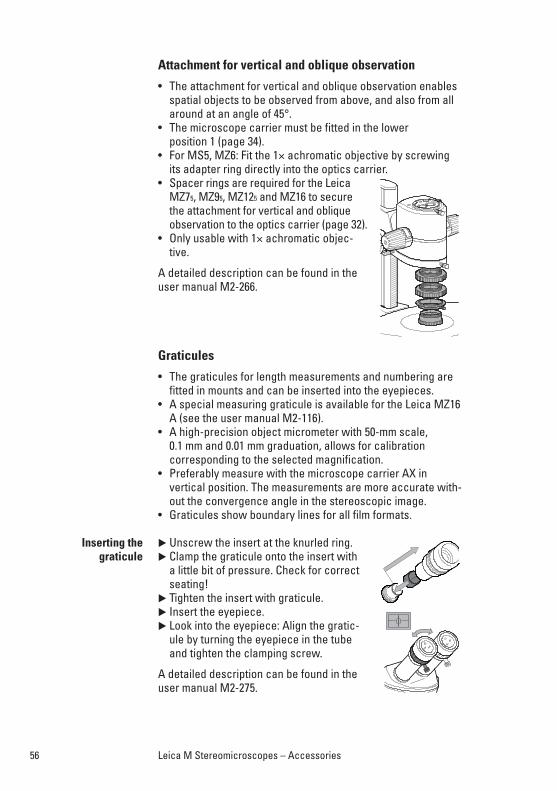
Attachment for vertical and oblique observation
• The attachment for vertical and oblique observation enablesspatial objects to be observed from above, and also from allaround at an angle of 45°.
• The microscope carrier must be fitted in the lower position 1 (page 34).
• For MS5, MZ6: Fit the 1× achromatic objective by screwingits adapter ring directly into the optics carrier.
• Spacer rings are required for the LeicaMZ75, MZ95, MZ125 and MZ16 to securethe attachment for vertical and obliqueobservation to the optics carrier (page 32).
• Only usable with 1× achromatic objec-tive.
A detailed description can be found in the user manual M2-266.
Graticules
• The graticules for length measurements and numbering arefitted in mounts and can be inserted into the eyepieces.
• A special measuring graticule is available for the Leica MZ16A (see the user manual M2-116).
• A high-precision object micrometer with 50-mm scale,0.1 mm and 0.01 mm graduation, allows for calibration corresponding to the selected magnification.
• Preferably measure with the microscope carrier AX in vertical position. The measurements are more accurate with-out the convergence angle in the stereoscopic image.
• Graticules show boundary lines for all film formats.
� Unscrew the insert at the knurled ring.� Clamp the graticule onto the insert with
a little bit of pressure. Check for correctseating!
� Tighten the insert with graticule.� Insert the eyepiece.� Look into the eyepiece: Align the gratic-
ule by turning the eyepiece in the tubeand tighten the clamping screw.
A detailed description can be found in theuser manual M2-275.
Inserting the graticule
56 Leica M Stereomicroscopes – Accessories
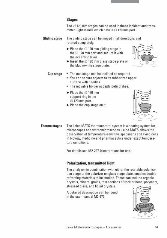
Stages
The ∅ 120 mm stages can be used in those incident and trans-mitted-light stands which have a ∅ 120 mm port.
The gliding stage can be moved in all directions and rotated completely.
� Place the ∅ 120 mm gliding stage in the ∅ 120 mm port and secure it with the eccentric lever.
� Insert the ∅ 120 mm glass stage plate orthe black/white stage plate.
• The cup stage can be inclined as required.• You can secure objects to its rubberized upper
surface with needles.• The movable holder accepts petri dishes.
� Place the ∅ 120 mm support ring in the ∅ 120 mm port.
� Place the cup stage on it.
The Leica MATS thermocontrol system is a heating system formicroscopes and stereomicroscopes. Leica MATS allows theobservation of temperature-sensitive specimens and living cellsin biology, medicine and pharmaceutics under exact tempera-ture conditions.
For details see M2-227-0 instructions for use.
Polarization, transmitted light
The analyzer, in combination with either the rotatable polariza-tion stage or the polarizer on glass stage plate, enables double-refracting materials to be studied. These can include organiccrystals, mineral grains, thin sections of rock or bone, polymers,stressed glass, and liquid crystals.
A detailed description can be found in the user manual M2-277.
Gliding stage
Cup stage
Thermo stages
57Leica M Stereomicroscopes – Accessories
58 Leica M Stereomicroscopes – Notes
Tips and hints: What to do if …
Remedy:
• Set the interpupillary distance correctly (page 15).• Locate the eyepoint (page 15).
Remedy:
• Fit the eyepieces correctly (page 35).• Adjust your dioptric settings exactly as described (page 20).
Remedy:
• Adjust the ease of movement (pages 16, 29, 31).
• Is the voltage selector set correctly (bright-field transmittedlight stand, page 24; transformer, page 38)?
• Is the power switch on?• Is the power cable attached correctly?• Are all connecting cables attached correctly?• Are the fuses in order?
Remedy:
• Turn up the regulating knob high enough (bright-field transmitted light stand, page 24; transformer, page 38).
• Open the double-iris diaphragm of the phototube.
TV, photography
Remedy:
• Adjust the video camera / monitor system in accordance with the directions of the manufacturer.
• Refer to the remedies listed above under "The image is too dark."
Remedy:
• Focus precisely (page 16).• Adjust your dioptric settings exactly as described (page 20).
Remedy:
• Use artificial-light film.• Turn the regulating knob of the transformer clockwise to the
position of maximum voltage (bright field transmitted-lightstand, page 24; transformer, page 38).
The field of view ispartly shadowed.
The image does notstay in focus.
The focusing driftsdownwards or can
be moved only withdifficulty.
If an electrical faultdevelops, first check
the following:
The image is too dark.
The image on the screen
is too dark.
Blurred photographs.
Color photographshave a yellow cast.
Notes
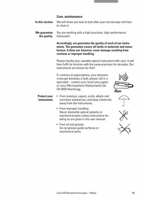
59Leica M Stereomicroscopes – Notes
Care, maintenance
We will show you how to look after your microscope and howto clean it.
You are working with a high-precision, high-performance instrument.
Accordingly, we guarantee the quality of each of our instru-ments. The guarantee covers all faults in materials and manu-facture. It does not, however, cover damage resulting fromcareless or improper handling.
Please handle your valuable optical instrument with care. It willthen fulfill its function with the same precision for decades. Ourinstruments are known for that!
If, contrary to expectations, your stereomi-croscope develops a fault, please call in aspecialist – contact your local Leica agent or Leica Microsystems (Switzerland) Ltd, CH-9435 Heerbrugg.
• From moisture, vapors, acids, alkalis and corrosive substances, and keep chemicalsaway from the instruments.
• From improper handling. Never dismantle optical systems or mechanical parts unless instructions fordoing so are given in the user manual.
• From oil and grease.Do not grease guide surfaces ormechanical parts.
In this section
We guarantee the quality.
Protect your instruments
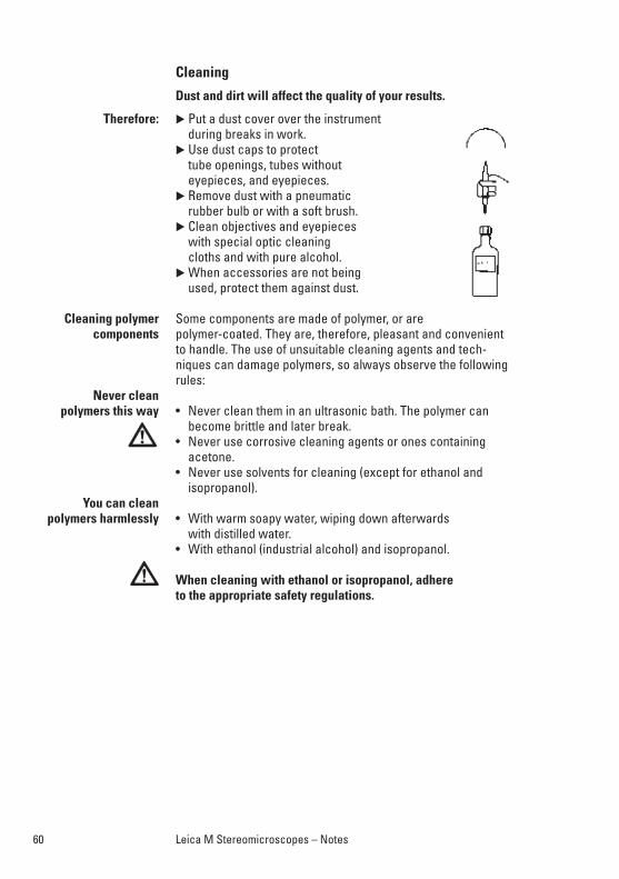
60 Leica M Stereomicroscopes – Notes
Cleaning
Dust and dirt will affect the quality of your results.
� Put a dust cover over the instrument during breaks in work.
� Use dust caps to protect tube openings, tubes without eyepieces, and eyepieces.
� Remove dust with a pneumatic rubber bulb or with a soft brush.
� Clean objectives and eyepieces with special optic cleaning cloths and with pure alcohol.
� When accessories are not being used, protect them against dust.
Some components are made of polymer, or arepolymer-coated. They are, therefore, pleasant and convenientto handle. The use of unsuitable cleaning agents and tech-niques can damage polymers, so always observe the followingrules:
• Never clean them in an ultrasonic bath. The polymer canbecome brittle and later break.
• Never use corrosive cleaning agents or ones containingacetone.
• Never use solvents for cleaning (except for ethanol andisopropanol).
• With warm soapy water, wiping down afterwards with distilled water.
• With ethanol (industrial alcohol) and isopropanol.
When cleaning with ethanol or isopropanol, adhere to the appropriate safety regulations.
Therefore:
Cleaning polymer components
Never clean polymers this way
You can clean polymers harmlessly
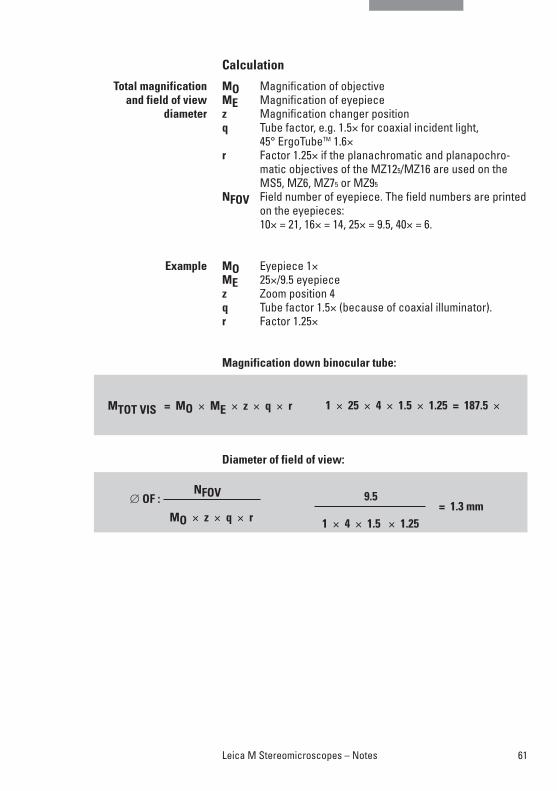
61Leica M Stereomicroscopes – Notes
Calculation
MO Magnification of objective ME Magnification of eyepiece z Magnification changer positionq Tube factor, e.g. 1.5× for coaxial incident light,
45° ErgoTubeTM 1.6×r Factor 1.25× if the planachromatic and planapochro-
matic objectives of the MZ125/MZ16 are used on theMS5, MZ6, MZ75 or MZ95
NFOV Field number of eyepiece. The field numbers are printedon the eyepieces:10× = 21, 16× = 14, 25× = 9.5, 40× = 6.
MO Eyepiece 1×ME 25×/9.5 eyepiecez Zoom position 4 q Tube factor 1.5× (because of coaxial illuminator).r Factor 1.25×
Magnification down binocular tube:
Diameter of field of view:
1 × 25 × 4 × 1.5 × 1.25 = 187.5 ×MTOT VIS = MO × ME × z × q × r
∅ OF :NFOV
MO × z × q × r
9.5 = 1.3 mm
1 × 4 × 1.5 × 1.25
Total magnificationand field of view
diameter
Example
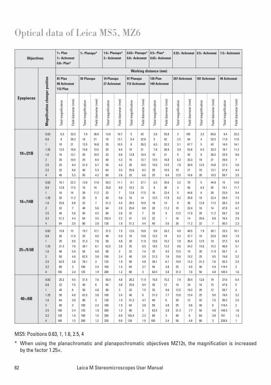
62 Leica M Stereomicroscopes User Manual
Optical data of Leica MS5, MZ6
Objectives
Working distance (mm)
Fiel
d di
amet
er (m
m)
Tota
l mag
nific
atio
n
0.63 25.2 9.5 31.5 7.6 50.4 4.8 20.2 11.9 15.8 15.2 7.9 30.4 12.6 19 37.6 6.4
0.8 32 7.5 40 6 64 3.8 25.6 9.4 20 12 10 24 16 15 47.8 5
1 40 6 50 4.8 80 3 32 7.5 25 9.6 12.5 19.2 20 12 59.7 4
1.25 50 4.8 62.5 3.8 100 2.4 40 6 31.3 7.7 15.6 15.4 25 9.6 74.6 3.2
1.6 64 3.8 80 3 128 1.9 51.2 4.7 40 6 20 12 32 7.5 95.5 2.5
2 80 3 100 2.4 160 1.5 64 3.8 50 4.8 25 9.6 40 6 119.4 2
2.5 100 2.4 125 1.9 200 1.2 80 3 62.5 3.8 31.3 7.7 50 4.8 149.3 1.6
3.2 128 1.9 160 1.5 256 0.9 102.4 2.3 80 3 40 6 64 3.8 191 1.3
4 160 1.5 200 1.2 320 0.8 128 1.9 100 2.4 50 4.8 80 3 238.8 1
0.63 15.8 15 19.7 12.1 31.5 7.5 12.6 18.8 9.8 24.2 4.9 48.5 7.9 30.1 23.5 10.1
0.8 20 11.9 25 9.5 40 5.9 16 14.8 12.5 19 6.3 37.7 10 23.8 29.9 7.9
1 25 9.5 31.3 7.6 50 4.8 20 11.9 15.6 15.2 7.8 30.4 12.5 19 37.3 6.4
1.25 31.3 7.6 39.1 6.1 62.5 3.8 25 9.5 19.5 12.2 9.8 24.2 15.6 15.2 46.6 5.1
1.6 40 5.9 50 4.8 80 3 32 7.4 25 9.5 12.5 19 20 11.9 59.7 4
2 50 4.8 62.5 3.8 100 2.4 40 5.9 31.3 7.6 15.6 15.2 25 9.5 74.6 3.2
2.5 62.5 3.8 78.1 3 125 1.9 50 4.8 39.1 6.1 19.5 12.2 31.3 7.6 93.3 2.5
3.2 80 3 100 2.4 160 1.5 64 3.7 50 4.8 25 9.5 40 5.9 119.4 2
4 100 2.4 125 1.9 200 1.2 80 3 62.5 3.8 31.3 7.6 50 4.8 149.3 1.6
0.63 10.1 22.2 12.6 17.8 20.2 11.1 8.1 27.7 6.3 35.6 3.2 70 5 44.8 15 14.9
0.8 12.8 17.5 16 14 25.6 8.8 10.2 22 8 28 4 56 6.4 35 19.1 11.7
1 16 14 20 11.2 32 7 12.8 17.5 10 22.4 5 44.8 8 28 23.9 9.4
1.25 20 11.2 25 9 40 5.6 16 14 12.5 17.9 6.3 35.6 10 22.4 29.9 7.5
1.6 25.6 8.8 32 7 51.2 4.4 20.5 10.9 16 14 8 28 12.8 17.5 38.2 5.9
2 32 7 40 5.6 64 3.5 25.6 8.8 20 11.2 10 22.4 16 14 47.8 4.7
2.5 40 5.6 50 4.5 80 2.8 32 7 25 9 12.5 17.9 20 11.2 59.7 3.8
3.2 51.2 4.4 64 3.5 102.4 2.2 41 5.5 32 7 16 14 25.6 8.8 76.4 2.9
4 64 3.5 80 2.8 128 1.8 51.2 4.4 40 5.6 20 11.2 32 7 95.5 2.3
0.63 6.3 33.3 7.9 26.6 12.6 16.7 5 42 3.9 53.8 2 105 3.2 65.6 9.4 22.3
0.8 8 26.3 10 21 16 13.1 6.4 32.8 5 42 2.5 84 4 52.5 11.9 17.6
1 10 21 12.5 16.8 20 10.5 8 26.3 6.3 33.3 3.1 67.7 5 42 14.9 14.1
1.25 12.5 16.8 15.6 13.5 25 8.4 10 21 7.8 26.9 3.9 53.8 6.3 33.3 18.7 11.2
1.6 16 13.1 20 10.5 32 6.6 12.8 16.4 10 21 5 42 8 26.3 23.9 8.8
2 20 10.5 25 8.4 40 5.3 16 13.1 12.5 16.8 6.3 33.3 10 21 29.9 7
2.5 25 8.4 31.3 6.7 50 4.2 20 10.5 15.6 13.5 7.8 26.9 12.5 16.8 37.3 5.6
3.2 32 6.6 40 5.3 64 3.3 25.6 8.2 20 10.5 10 21 16 13.1 47.8 4.4
4 40 5.3 50 4.2 80 2.6 32 6.6 25 8.4 12.5 16.8 20 10.5 59.7 3.5
10×/21B
16×/14B
25×/9.5B
40×/6B
Eyepieces
Tota
l mag
nific
atio
n
Fiel
d di
amet
er (m
m)
Tota
l mag
nific
atio
n
Fiel
d di
amet
er (m
m)
Tota
l mag
nific
atio
n
Fiel
d di
amet
er (m
m)
Tota
l mag
nific
atio
n
Fiel
d di
amet
er (m
m)
Tota
l mag
nific
atio
n
Fiel
d di
amet
er (m
m)
Tota
l mag
nific
atio
n
Fiel
d di
amet
er (m
m)
Tota
l mag
nific
atio
n
Fiel
d di
amet
er (m
m)
1× Plan 1× Achromat0.8× Plan*
81 Plan89 Achromat112 Plan
55 Planapo 19 Planapo27 Achromat
97 Planapo112 Achromat
135 Plan149 Achromat
297 Achromat 187 Achromat 49 Achromat
1× Planapo* 1.6× Planapo*2× Achromat
0.63× Planapo*0.8× Achromat
0.5× Plan*0.63× Achromat
0.32× Achromat 0.5× Achromat 1.5× Achromat
Mag
nific
atio
n ch
ange
r pos
ition
MS5: Positions 0.63, 1, 1.6, 2.5, 4
* When using the planachromatic and planapochromatic objectives MZ125, the magnification is increased by the factor 1.25×.
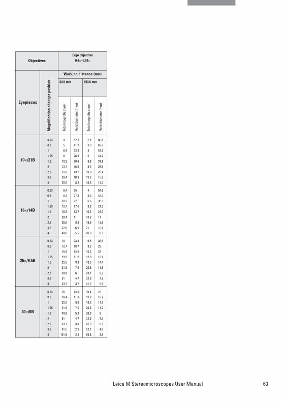
63Leica M Stereomicroscopes User Manual
Objectives
Working distance (mm)
0.63 16 14.9 10.4 23
0.8 20.4 11.8 13.2 18.2
1 25.5 9.4 16.5 14.5
1.25 31.8 7.5 20.6 11.7
1.6 40.8 5.9 26.3 9
2 51 4.7 32.9 7.3
2.5 63.7 3.8 41.2 5.8
3.2 81.5 2.9 52.7 4.6
4 101.9 2.4 65.8 3.6
0.63 10 23.8 6.5 36.5
0.8 12.7 18.7 8.2 29
1 15.9 14.9 10.3 23
1.25 19.9 11.9 12.9 18.4
1.6 25.5 9.3 16.5 14.4
2 31.8 7.5 20.6 11.5
2.5 39.8 6 25.7 9.2
3.2 51 4.7 32.9 7.2
4 63.7 3.7 41.2 5.8
0.63 6.4 35 4 54.6
0.8 8.2 27.3 5.3 42.3
1 10.2 22 6.6 33.9
1.25 12.7 17.6 8.2 27.3
1.6 16.3 13.7 10.5 21.3
2 20.4 11 13.2 17
2.5 25.5 8.8 16.5 13.6
3.2 32.6 6.9 21 10.6
4 40.8 5.5 26.3 8.5
0.63 4 52.5 2.6 80.8
0.8 5 41.2 3.3 63.6
1 6.4 32.8 4 51.2
1.25 8 26.3 5 41.2
1.6 10.2 20.6 6.6 31.8
2 12.7 16.5 8.2 25.6
2.5 15.9 13.2 10.3 20.4
3.2 20.4 10.3 13.2 15.9
4 25.5 8.2 16.5 12.7
10×/21B
16×/14B
25×/9.5B
40×/6B
Eyepieces
Tota
l mag
nific
atio
n
Fiel
d di
amet
er (m
m)
Tota
l mag
nific
atio
n
Fiel
d di
amet
er (m
m)
Ergo objective0.4×–0.63×
63.5 mm 153.5 mm
Mag
nific
atio
n ch
ange
r pos
ition
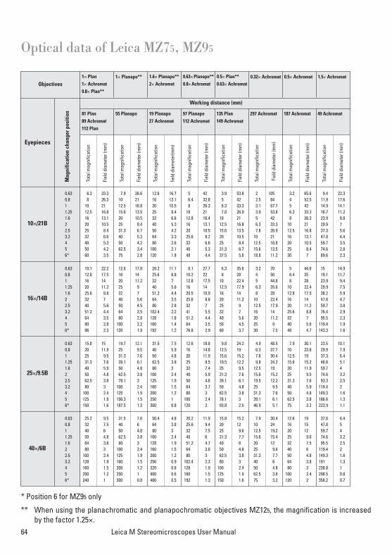
64 Leica M Stereomicroscopes User Manual
Optical data of Leica MZ75, MZ95
Objectives
40×/6B
0.63 25.2 9.5 31.5 7.6 50.4 4.8 20.2 11.9 15.8 15.2 7.9 30.4 12.6 19 37.6 6.4 0.8 32 7.5 40 6 64 3.8 25.6 9.4 20 12 10 24 16 15 47.8 5 1 40 6 50 4.8 80 3 32 7.5 25 9.6 12.5 19.2 20 12 59.7 4 1.25 50 4.8 62.5 3.8 100 2.4 40 6 31.3 7.7 15.6 15.4 25 9.6 74.6 3.2 1.6 64 3.8 80 3 128 1.9 51.2 4.7 40 6 20 12 32 7.5 95.5 2.5 2 80 3 100 2.4 160 1.5 64 3.8 50 4.8 25 9.6 40 6 119.4 2 2.5 100 2.4 125 1.9 200 1.2 80 3 62.5 3.8 31.3 7.7 50 4.8 149.3 1.6 3.2 128 1.9 160 1.5 256 0.9 102.4 2.3 80 3 40 6 64 3.8 191 1.3 4 160 1.5 200 1.2 320 0.8 128 1.9 100 2.4 50 4.8 80 3 238.8 1 5 200 1.2 250 1 400 0.6 160 1.5 125 1.9 62.5 3.8 100 2.4 298.5 0.8 6* 240 1 300 0.8 480 0.5 192 1.3 150 1.6 75 3.2 120 2 358.2 0.7
0.63 15.8 15 19.7 12.1 31.5 7.5 12.6 18.8 9.8 24.2 4.9 48.5 7.9 30.1 23.5 10.1 0.8 20 11.9 25 9.5 40 5.9 16 14.8 12.5 19 6.3 37.7 10 23.8 29.9 7.9 1 25 9.5 31.3 7.6 50 4.8 20 11.9 15.6 15.2 7.8 30.4 12.5 19 37.3 6.4 1.25 31.3 7.6 39.1 6.1 62.5 3.8 25 9.5 19.5 12.2 9.8 24.2 15.6 15.2 46.6 5.1 1.6 40 5.9 50 4.8 80 3 32 7.4 25 9.5 12.5 19 20 11.9 59.7 4 2 50 4.8 62.5 3.8 100 2.4 40 5.9 31.3 7.6 15.6 15.2 25 9.5 74.6 3.2 2.5 62.5 3.8 78.1 3 125 1.9 50 4.8 39.1 6.1 19.5 12.2 31.3 7.6 93.3 2.5 3.2 80 3 100 2.4 160 1.5 64 3.7 50 4.8 25 9.5 40 5.9 119.4 2 4 100 2.4 125 1.9 200 1.2 80 3 62.5 3.8 31.3 7.6 50 4.8 149.3 1.6 5 125 1.9 156.3 1.5 250 1 100 2.4 78.1 3 39.1 6.1 62.5 3.8 186.6 1.3 6* 150 1.6 187.5 1.3 300 0.8 120 2 93.8 2.5 46.9 5.1 75 3.2 223.9 1.1
0.63 10.1 22.2 12.6 17.8 20.2 11.1 8.1 27.7 6.3 35.6 3.2 70 5 44.8 15 14.9 0.8 12.8 17.5 16 14 25.6 8.8 10.2 22 8 28 4 56 6.4 35 19.1 11.7 1 16 14 20 11.2 32 7 12.8 17.5 10 22.4 5 44.8 8 28 23.9 9.4 1.25 20 11.2 25 9 40 5.6 16 14 12.5 17.9 6.3 35.6 10 22.4 29.9 7.5 1.6 25.6 8.8 32 7 51.2 4.4 20.5 10.9 16 14 8 28 12.8 17.5 38.2 5.9 2 32 7 40 5.6 64 3.5 25.6 8.8 20 11.2 10 22.4 16 14 47.8 4.7 2.5 40 5.6 50 4.5 80 2.8 32 7 25 9 12.5 17.9 20 11.2 59.7 3.8 3.2 51.2 4.4 64 3.5 102.4 2.2 41 5.5 32 7 16 14 25.6 8.8 76.4 2.9 4 64 3.5 80 2.8 128 1.8 51.2 4.4 40 5.6 20 11.2 32 7 95.5 2.3 5 80 2.8 100 2.2 160 1.4 64 3.5 50 4.5 25 9 40 5.6 119.4 1.9 6* 96 2.3 120 1.9 192 1.2 76.8 2.9 60 3.7 30 7.5 48 4.7 143.3 1.6
0.63 6.3 33.3 7.9 26.6 12.6 16.7 5 42 3.9 53.8 2 105 3.2 65.6 9.4 22.3 0.8 8 26.3 10 21 16 13.1 6.4 32.8 5 42 2.5 84 4 52.5 11.9 17.6 1 10 21 12.5 16.8 20 10.5 8 26.3 6.3 33.3 3.1 67.7 5 42 14.9 14.1 1.25 12.5 16.8 15.6 13.5 25 8.4 10 21 7.8 26.9 3.9 53.8 6.3 33.3 18.7 11.2 1.6 16 13.1 20 10.5 32 6.6 12.8 16.4 10 21 5 42 8 26.3 23.9 8.8 2 20 10.5 25 8.4 40 5.3 16 13.1 12.5 16.8 6.3 33.3 10 21 29.9 7 2.5 25 8.4 31.3 6.7 50 4.2 20 10.5 15.6 13.5 7.8 26.9 12.5 16.8 37.3 5.6 3.2 32 6.6 40 5.3 64 3.3 25.6 8.2 20 10.5 10 21 16 13.1 47.8 4.4 4 40 5.3 50 4.2 80 2.6 32 6.6 25 8.4 12.5 16.8 20 10.5 59.7 3.5 5 50 4.2 62.5 3.4 100 2.1 40 5.3 31.3 6.7 15.6 13.5 25 8.4 74.6 2.8 6* 60 3.5 75 2.8 120 1.8 48 4.4 37.5 5.6 18.8 11.2 30 7 89.6 2.3
Working distance (mm)
10×/21B
Eyepieces
16×/14B
25×/9.5B
Tota
l mag
nific
atio
n
Fiel
d di
amet
er (m
m)
Tota
l mag
nific
atio
n
Fiel
d di
amet
er (m
m)
Tota
l mag
nific
atio
n
field
dia
met
er(m
m)
Tota
l mag
nific
atio
n
Fiel
d di
amet
er (m
m)
Tota
l mag
nific
atio
n
Fiel
d di
amet
er (m
m)
Tota
l mag
nific
atio
n
Fiel
d di
amet
er (m
m)
Tota
l mag
nific
atio
n
Fiel
d di
amet
er (m
m)
Tota
l mag
nific
atio
n
Fiel
d di
amet
er (m
m)
1× Plan 1× Achromat0.8× Plan**
81 Plan89 Achromat112 Plan
55 Planapo 19 Planapo27 Achromat
97 Planapo112 Achromat
135 Plan149 Achromat
297 Achromat 187 Achromat 49 Achromat
1× Planapo** 1.6× Planapo**2× Achromat
0.63× Planapo**0.8× Achromat
0.5× Plan**0.63× Achromat
0.32× Achromat 0.5× Achromat 1.5× Achromat
Mag
nific
atio
n ch
ange
r pos
ition
* Position 6 for MZ95 only
** When using the planachromatic and planapochromatic objectives MZ125, the magnification is increasedby the factor 1.25×.
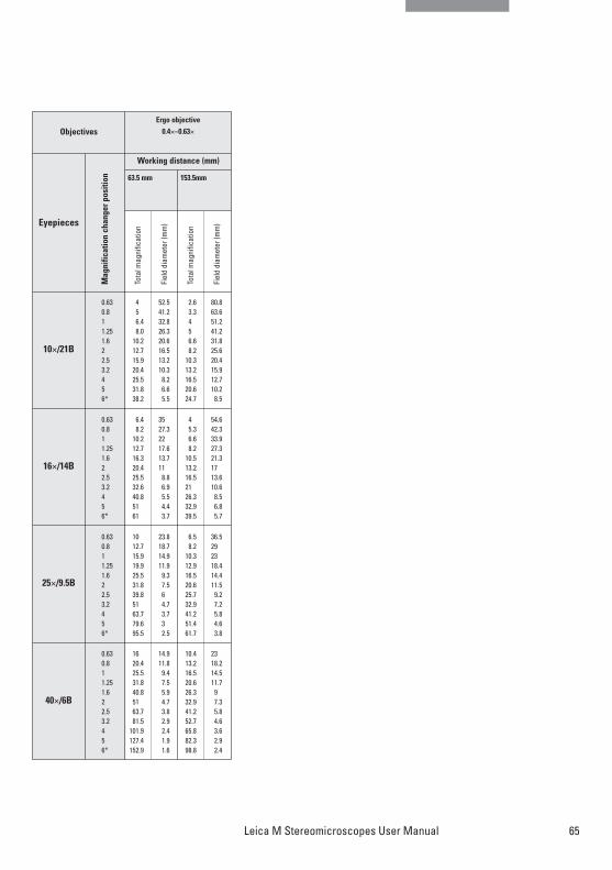
65Leica M Stereomicroscopes User Manual
Objectives
40×/6B
0.63 16 14.9 10.4 230.8 20.4 11.8 13.2 18.2 1 25.5 9.4 16.5 14.5 1.25 31.8 7.5 20.6 11.7 1.6 40.8 5.9 26.3 92 51 4.7 32.9 7.3 2.5 63.7 3.8 41.2 5.8 3.2 81.5 2.9 52.7 4.6 4 101.9 2.4 65.8 3.6 5 127.4 1.9 82.3 2.9 6* 152.9 1.6 98.8 2.4
0.63 10 23.8 6.5 36.5 0.8 12.7 18.7 8.2 291 15.9 14.9 10.3 231.25 19.9 11.9 12.9 18.4 1.6 25.5 9.3 16.5 14.4 2 31.8 7.5 20.6 11.5 2.5 39.8 6 25.7 9.2 3.2 51 4.7 32.9 7.2 4 63.7 3.7 41.2 5.8 5 79.6 3 51.4 4.6 6* 95.5 2.5 61.7 3.8
0.63 6.4 35 4 54.60.8 8.2 27.3 5.3 42.3 1 10.2 22 6.6 33.9 1.25 12.7 17.6 8.2 27.3 1.6 16.3 13.7 10.5 21.3 2 20.4 11 13.2 172.5 25.5 8.8 16.5 13.6 3.2 32.6 6.9 21 10.6 4 40.8 5.5 26.3 8.5 5 51 4.4 32.9 6.8 6* 61 3.7 39.5 5.7
0.63 4 52.5 2.6 80.8 0.8 5 41.2 3.3 63.6 1 6.4 32.8 4 51.2 1.25 8.0 26.3 5 41.2 1.6 10.2 20.6 6.6 31.8 2 12.7 16.5 8.2 25.6 2.5 15.9 13.2 10.3 20.4 3.2 20.4 10.3 13.2 15.9 4 25.5 8.2 16.5 12.7 5 31.8 6.6 20.6 10.2 6* 38.2 5.5 24.7 8.5
Working distance (mm)
10×/21B
Eyepieces
16×/14B
25×/9.5B
Tota
l mag
nific
atio
n
Fiel
d di
amet
er (m
m)
Tota
l mag
nific
atio
n
Fiel
d di
amet
er (m
m)
Ergo objective0.4×–0.63×
63.5 mm 153.5mm
Mag
nific
atio
n ch
ange
r pos
ition
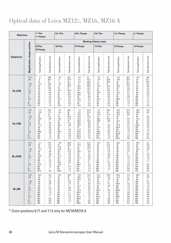
66 Leica M Stereomicroscopes User Manual
Optical data of Leica MZ125, MZ16, MZ16 A
Eyepieces
Working distance (mm)
Objectives
0.71 28.4 8.4 14.2 16.9 17.9 13.4 22.7 10.5 45.4 5.3 56.8 4.20.8 32 7.5 16 15 20.5 11.7 25.6 9.4 51.2 4.7 64 3.81 40 6 20 12 25.6 9.4 32 7.5 64 3.8 80 31.25 50 4.8 25 9.6 32 7.5 40 6 80 3 100 2.41.6 64 3.8 32 7.5 41 5.9 51.2 4.7 102.4 2.3 128 1.92 80 3 40 6 51.2 4.7 64 3.8 128 1.9 160 1.52.5 100 2.4 50 4.8 64 3.8 80 3 160 1.5 200 1.23.2 128 1.9 64 3.8 81.9 2.9 102.4 2.3 204.8 1.2 256 0.94 160 1.5 80 3 102.4 2.3 128 1.9 256 0.9 320 0.85 200 1.2 100 2.4 128 1.9 160 1.5 320 0.8 400 0.66.3 252 1 126 1.9 161.3 1.5 201.6 1.2 403.2 0.6 504 0.58 320 0.8 160 1.5 204.8 1.2 256 0.9 512 0.5 640 0.4
10 400 0.6 200 1.2 256 0.9 320 0.8 640 0.4 800 0.311.5 460 0.5 230 1 289.8 0.8 368 0.6 736 0.3 920 0.3
0.71 17.7 13.4 8.9 26.8 11.1 21.2 14.2 16.7 28.3 8.4 35.4 6.70.8 20 11.9 10 23.8 12.8 18.6 16 14.8 32 7.4 40 5.91 25 9.5 12.5 19 16 14.8 20 11.9 40 5.9 50 4.81.25 31.3 7.6 15.6 15.2 20 11.9 25 9.5 50 4.8 62.5 3.81.6 40 5.9 20 11.9 25.6 9.3 32 7.4 64 3.7 80 32 50 4.8 25 9.5 32 7.4 40 5.9 80 3 100 2.42.5 62.5 3.8 31.3 7.6 40 5.9 50 4.8 100 2.4 125 1.93.2 80 3 40 5.9 51.2 4.6 64 3.7 128 1.9 160 1.54 100 2.4 50 4.8 64 3.7 80 3 160 1.5 200 1.25 125 1.9 62.5 3.8 80 3 100 2.4 200 1.2 250 16.3 157.5 1.5 78.8 3 100.8 2.4 126 1.9 252 0.9 315 0.88 200 1.2 100 2.4 128 1.9 160 1.5 320 0.7 400 0.6
10 250 1 125 1.9 160 1.5 200 1.2 400 0.6 500 0.511.5 287.5 0.8 143.8 1.7 181.1 1.3 230 1 460 0.5 575 0.4
0.71 11.4 19.7 5.7 39.4 7.2 31.3 9.1 24.6 18.2 12.3 22.8 9.80.8 12.8 17.5 6.4 35 8.2 27.3 10.2 22 20.5 10.9 25.6 8.81 16 14 8 28 10.2 22 12.8 17.5 25.6 8.8 32 71.25 20 11.2 10 22.4 12.8 17.5 16 14 32 7 40 5.61.6 25.6 8.8 12.8 17.5 16.4 13.7 20.5 10.9 41 5.5 51.2 4.42 32 7 16 14 20.5 10.9 25.6 8.8 51.2 4.4 64 3.52.5 40 5.6 20 11.2 25.6 8.8 32 7 64 3.5 80 2.83.2 51.2 4.4 25.6 8.8 32.8 6.8 41 5.5 81.9 2.7 102.4 2.24 64 3.5 32 7 41 5.5 51.2 4.4 102.4 2.2 128 1.85 80 2.8 40 5.6 51.2 4.4 64 3.5 128 1.8 160 1.46.3 100.8 2.2 50.4 4.4 64.5 3.5 80.6 2.8 161.3 1.4 201.6 1.18 128 1.8 64 3.5 81.9 2.7 102.4 2.2 204.8 1.1 256 0.9
10 160 1.4 80 2.8 102.4 2.2 128 1.8 256 0.9 320 0.711.5 184 1.2 92 2.4 115.9 1.9 147.2 1.5 294.4 0.8 368 0.6
0.71 7.1 29.6 3.5 59.1 4.5 47 5.7 37 11.4 18.5 14.2 14.80.8 8 26.3 4 52.5 5.1 41.2 6.4 32.8 12.8 16.4 16 13.11 10 21 5 42 6.4 32.8 8 26.3 16 13.1 20 10.51.25 12.5 16.8 6.3 33.3 8 26.3 10 21 20 10.5 25 8.41.6 16 13.1 8 26.3 10.2 20.6 12.8 16.4 25.6 8.2 32 6.62 20 10.5 10 21 12.8 16.4 16 13.1 32 6.6 40 5.32.5 25 8.4 12.5 16.8 16 13.1 20 10.5 40 5.3 50 4.23.2 32 6.6 16 13.1 20.5 10.2 25.6 8.2 51.2 4.1 64 3.34 40 5.3 20 10.5 25.6 8.2 32 6.6 64 3.3 80 2.65 50 4.2 25 8.4 32 6.6 40 5.3 80 2.6 100 2.16.3 63 3.3 31.5 6.7 40.3 5.2 50.4 4.2 100.8 2.1 126 1.78 80 2.6 40 5.3 51.2 4.1 64 3.3 128 1.6 160 1.3
10 100 2.1 50 4.2 64 3.3 80 2.6 160 1.3 200 1.111.5 115 1.8 57.5 3.7 72.5 2.9 92 2.2 184 1.1 230 0.9
10×/21B
16×/14B
25×/9.5B
40×/6B
Tota
l mag
nific
atio
n
Fiel
d di
amet
er (m
m)
Tota
l mag
nific
atio
n
Fiel
d di
amet
er (m
m)
Tota
l mag
nific
atio
n
Fiel
d di
amet
er (m
m)
Tota
l mag
nific
atio
n
Fiel
d di
amet
er (m
m)
Tota
l mag
nific
atio
n
Fiel
d di
amet
er (m
m)
Tota
l mag
nific
atio
n
Fiel
d di
amet
er (m
m)
1× Plan 1× Planapo
60 Plan 55 Planapo
135 Plan 97 Planapo 112 Plan 19 Planapo
0.5× Plan 0.63× Planapo 0.8× Plan 1.6× Planapo
15 Planapo
2× Planapo
Mag
nific
atio
n ch
ange
r pos
ition
* Zoom positions 0.71 and 11.5 only for MZ16/MZ16 A
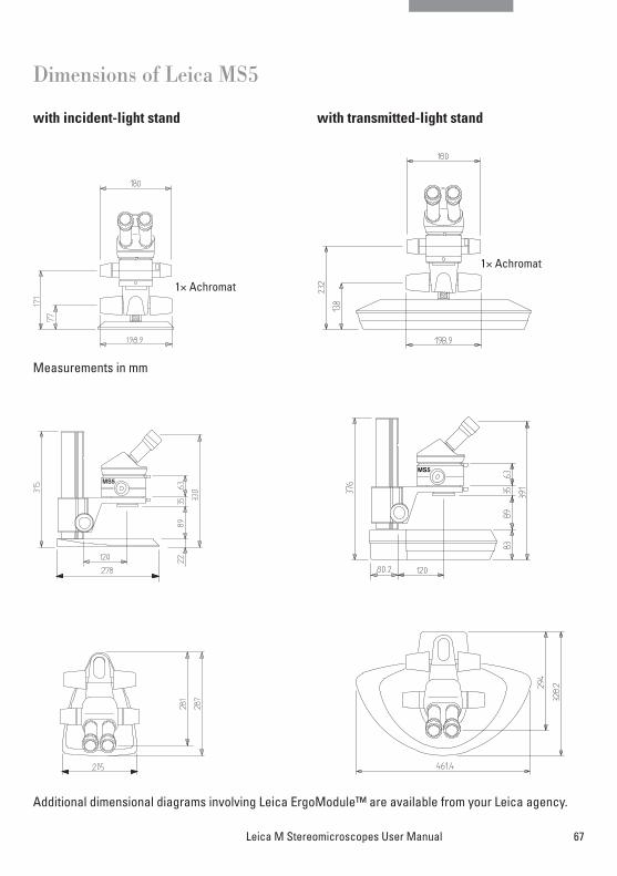
67Leica M Stereomicroscopes User Manual
MS5
1.0x Achromat
MS5
Dimensions of Leica MS5
with incident-light stand with transmitted-light stand
Additional dimensional diagrams involving Leica ErgoModule™ are available from your Leica agency.
Measurements in mm
1× Achromat
1× Achromat
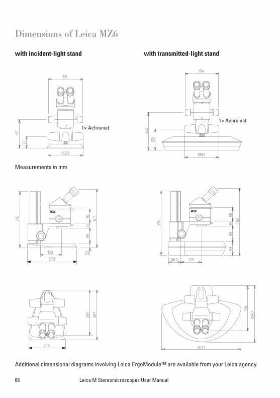
68 Leica M Stereomicroscopes User Manual
Dimensions of Leica MZ6
with incident-light stand with transmitted-light stand
Additional dimensional diagrams involving Leica ErgoModule™ are available from your Leica agency.
MZ6 MZ6
1.0x Achromat
Measurements in mm
1× Achromat1× Achromat
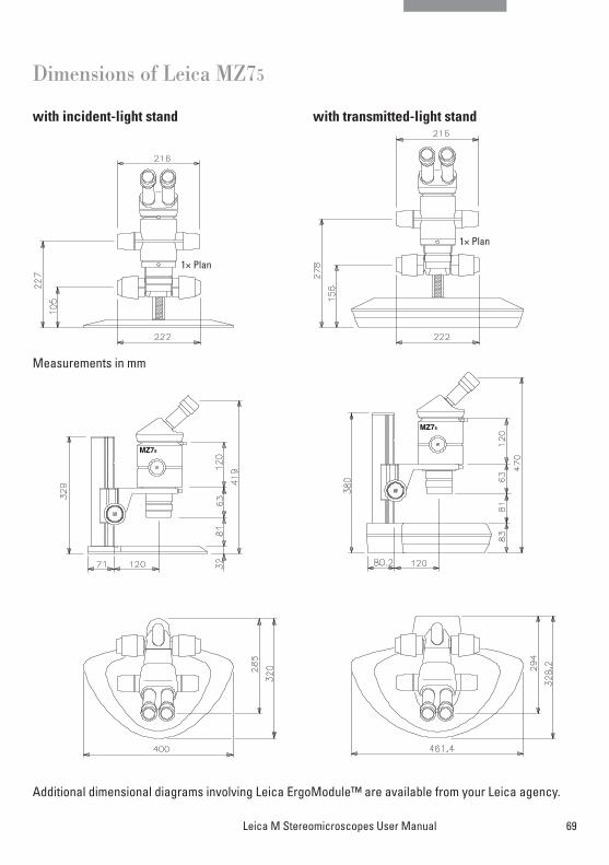
69Leica M Stereomicroscopes User Manual
Dimensions of Leica MZ75
with incident-light stand with transmitted-light stand
Additional dimensional diagrams involving Leica ErgoModule™ are available from your Leica agency.
1.0x Plan
1.0x Plan
MZ75
MZ75
Measurements in mm
1× Plan
1× Plan
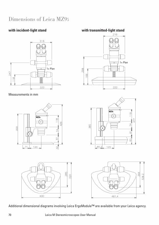
70 Leica M Stereomicroscopes User Manual
Dimensions of Leica MZ95
with incident-light stand with transmitted-light stand
Additional dimensional diagrams involving Leica ErgoModule™ are available from your Leica agency.
1.0x Plan
1.0x Plan
MZ95
MZ95
Measurements in mm
1× Plan
1× Plan
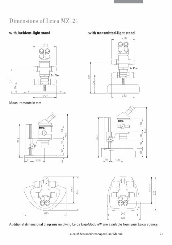
71Leica M Stereomicroscopes User Manual
Dimensions of Leica MZ125
with incident-light stand with transmitted-light stand
Additional dimensional diagrams involving Leica ErgoModule™ are available from your Leica agency.
1.0x Plan
1.0x Plan
MZ125
MZ125
Measurements in mm
1× Plan
1× Plan
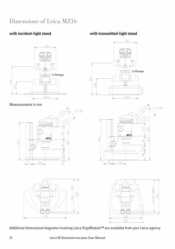
1x Planapo1x Planapo
MZ16
MZ16
72 Leica M Stereomicroscopes User Manual
Dimensions of Leica MZ16
with incident-light stand with transmitted-light stand
Additional dimensional diagrams involving Leica ErgoModule™ are available from your Leica agency.
Measurements in mm
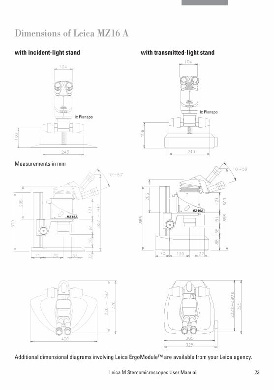
73Leica M Stereomicroscopes User Manual
Additional dimensional diagrams involving Leica ErgoModule™ are available from your Leica agency.
Dimensions of Leica MZ16 A
with incident-light stand with transmitted-light stand
Measurements in mm