LEHIGH UNIVERSITY I
87
«73 18528 IFSM -72-32 „«*». I A R c ;H U A T IM s s LEHIGH UNIVERSITY I HYDROGEN ADSORPTION AND DIFFUSION, AND SUBCRITICAL-CRACK GROWTH IN HIGH-STRENGTH STEELS AND NICKEL BASE ALLOYS First Annual Report November 1, 1971 to October 31, 1972 CAS COPY R. P. Wei K. Klier G. W. Simmons E. Chornet il V AV January 1973 National Aeronautics and Space Administration Grant NCR 39-007-067
Transcript of LEHIGH UNIVERSITY I

« 7 3 1 8 5 2 8IFSM -72-32
„«*».
I A
R c
;HU AT IM
s s
LEHIGH UNIVERSITY I
HYDROGEN ADSORPTION AND DIFFUSION, ANDSUBCRITICAL-CRACK GROWTH IN HIGH-STRENGTH
STEELS AND NICKEL BASE ALLOYS
First Annual Report
November 1, 1971 to October 31, 1972
CASCOPY R. P. Wei
K. KlierG. W. Simmons
E. Chornet
i l V AV January 1973
National Aeronautics and Space Administration
Grant NCR 39-007-067

F I R S T A N N U A L R E P O R T
SUBJECT: NASA Grant NCR 39-007-067"Hydrogen Adsorption and Diffusion, and Subcritlcal-Crack Growth in High-Strength Steels and NickelBase Alloys"First Annual Report - November 1, 1971 to
October 31, 1972
ATTENTION: Mr. John Misencik
NASA Lewis Research Center21000 Brookpark RoadCleveland, Ohio 44135
PREPARED BY: Drs. R. P. Wei, K. Klier,G. W. Simmons, and E. ChornetLEHIGH UNIVERSITYBethlehem, Pennsylvania 18015

FIRST ANNUAL REPORTNASA GRANT NCR 39-007-067
HYDROGEN ADSORPTION AND DIFFUSION, AND SUBCRITICAL-CRACKGROWTH IN HIGH-STRENGTH STEELS AND NICKEL BASE ALLOYS
by
R. P. Wei, K. KLier, G. W. Simmons and E. ChornetLEHIGH UNIVERSITY
Bethlehem, Pennsylvania\
ABSTRACT\
Embrlttlement, or the enhancement of crack growth by gaseous hydrogen inhigh-strength alloys, is of primary interest in selecting alloys for various componentsin the Space Shuttle. Embrittlement is known to occur at hydrogen gas pressuresranging from fractions to several hundred atmospheres, and is most severe hi thecase of martensitic high-strength steels. Kinetic information on subcritical-crackgrowth in gaseous hydrogen is sparse at this time. Corroborative information onhydrogen adsorption and diffusion is inadequate to permit a clear determination ofthe rate controlling process and possible, mechanism in hydrogen enhanced crackgrowth, and for estimating behavior over a range of temperatures and pressures.Therefore, coordinated studies of the kinetics of crack growth, and adsorption anddiffusion of hydrogen, using identical materials, have been initiated. Comparableconditions of temperature and pressure will be used in the chemical and mechanicalexperiments. Inconel 718 alloy and 18Ni(200) maraging steel have been selected forthese studies. Results from these studies are expected to provide not only a betterunderstanding of the gaseous hydrogen embrittlement phenomenon itself, but alsofundamental information on hydrogen adsorption and diffusion, and crack growthmformation that can be used directly for design.
No sustained-load crack growth was observed for the Inconel 718 alloy higaseous hydrogen (~1000 torr) at about -50°C, 25°C and +300°C for stress intensitiesup to 90 ksi -/in. The rate of fatigue crack growth at room temperature, with R =Kmin/Kmax = 0-5 an{l f = 5. 0 Hz, was also unaffected by gaseous hydrogen (atxx/1000torr).
Preliminary results on the 18Ni(200) maraging steel indicate that sustained-load crack growth was unaffected by hydrogen (~1000 torr) at room temperature,but was affected by hydrogen at about -30°C. The rate limiting speed was about1.5 x 10~4 in./sec at -30°C, and was about 1/5 of that for the 18Ni(250) maragingsteel. These very preliminary results suggest that the rate and temperaturedependence for hydrogen enhanced crack growth is a function of alloy compositionand/or of strengthleveL Additional experiments are in progress.
The surface activity toward hydrogen exchange reactions of the 18Ni(250)maraging steel, 18Ni(200) maraging steel, and of iron single crystal of (111)orientation was investigated. The 18Ni(250) maraging steel was studied as an

-2-
additlonal material not included in the original proposal. The rates of hydrogen 'atomization by the three types of materials are high and probably sufficient to sus-tain the crack growth through a mechanism limited by hydrogen atom formation.The order of activities for the formation of surface hydrogen atoms from the gasmolecules has been found to be:
Fe (111) > 18Ni(200) > 18Ni(250)
Aged specimens were found to be more active than non-aged specimens, and highlyperturbed surfaces were more active than annealed surfaces. It appears that theprevention of hydrogen embrittlement in maraging steels should be sought in addingalloying elements which would poison the catalytic activity of the surface for hydrogenatomization, or which would act as traps for hydrogen atoms preventing their sur-face diffusion. No significant bulk diffusion was observed in the range of temperaturesbetween -190 and 300°C in any of the materials studied. The testing of the Inconel718 alloy and an austenitic (316) stainless steel for surface reactivity toward hydro-gen is planned for the second year of the project.

-3-
FIRST ANNUAL REPORTNASA GRANT NCR 39-007-067
HYDROGEN ADSORPTION AND DIFFUSION, AND SUBCRITICAL-CRACKGROWTH IN HIGH-STRENGTH STEELS AND NICKEL BASE ALLOYS
I. JNTRQDUCTION
The embrittling effect of hydrogen on the fracture behavior of steels and certain
nickel-base alloys is well known and is of great technological importance. In general,
hydrogen embrittlement problems may be broadly separated into those that are caused
by dissolved hydrogen* (introduced by prior treatments or chemical reactions) and those
that result from the exposure to gaseous hydrogen environment during service, at pres-
sures ranging from tens of torrs to several hundred atmospheres. The problems of
embrittlement by hydrogen in solution have been investigated extensively and several
mechanisms have been proposed to explain the observed behavior. The first mechanism,
the pressure mechanism, suggests that embrittlement is caused by the development
of high pressures within internal voids. The pressure build-up results from the
accumulation of molecular hydrogen formed from hydrogen that diffuses into these
voids [1-4], The second, the lattice-interaction mechanism, suggests that hydrogen
would diffuse to regions of high hydrostatic tension within the lattice, under the influence
of a strong stress gradient near the crack tip, and interact with the metal and reduce
its cohesive strength [5-8]. The precise nature of the hydrogen-metal interaction is
not clearly defined. The third proposed mechanism is the stress-sorption mechanism
which suggests the reduction in fracture stress, vis a vis, embrittlement, arises from
a reduction in surface energy caused by the adsorption of hydrogen on the surfaces of
* Dissolved hydrogen includes hydrogen dissolved in the crystal lattice, as well as,hydrogen trapped at dislocations, intergranular space and voids.

-4-
internal voids [9].
These proposed mechanisms vary widely in rigor and acceptability. The pressure
mechanism has been well documented and is generally accepted for explaining phenomena
such as quench cracking of steel ingots and forgings, and embrittlement under hydrogen
charging conditions [2-4]. Its applicability to cracking of high-strength steels in
mildly corrosive environments, such as distilled water, has been seriously questioned
[4,10] (although it appears to be the most plausible mechanism for moisture-enhanced
fatigue-crack growth in aluminum and aluminum alloys [11-14].) The other two mecha-
nisms are less established and still need to be tested critically.
Embrittlement by gaseous hydrogen has begun to receive serious attention only
in the past few years [15-20]. The effect of gaseous hydrogen at 1 atmosphere on sub-
critical-crack growth in high-strength steels at room temperature was studied by
Hancock and Johnson [15] and Wei and Landes [16] for static loading, and by Spitzig,
et al. [17] and Wei and Landes [16] for fatigue. Crack growth studies at low hydrogen
pressures and in partially dissociated hydrogen were carried out by Williams and
Nelson [18] and Nelson, et al [19] on an AISI 4130 steel over a range of test temperatures.
Hydrogen embrittlement caused by gaseous hydrogen at pressures up to 10,000 psi on
smooth and notched bars for a variety of materials was investigated by Walter [20], These
investigations indicated that the high-strength martensitic steels are severely embrittled
by gaseous hydrogen at pressures ranging from *^100 torr to several hundred atmos-
pheres [15-20]. Nickel-base alloys such as Inconel 718 are also embrittled [20].
Austenltlc steels, on the other hand, experienced little or no embrittlement [20]. On
the basis of their experimental data, Williams and Nelson suggested that the rate con-
trolling process in hydrogen enhanced crack growth is that of adsorption of hydrogen
-5-
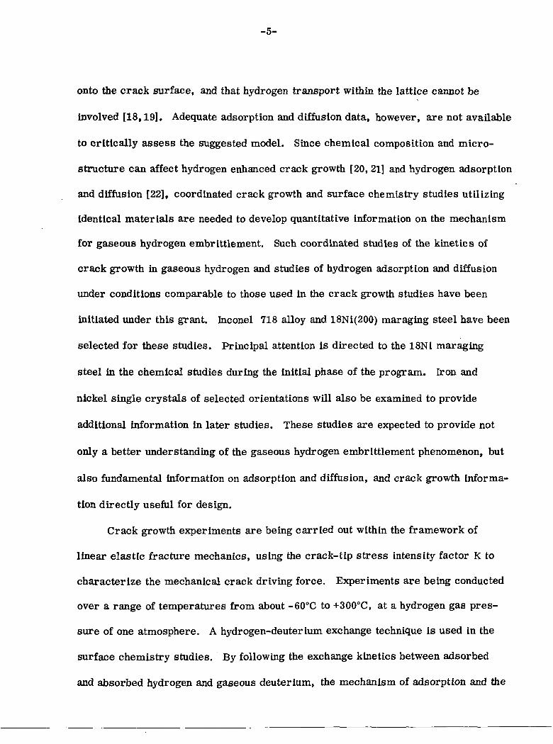
onto the crack surface, and that hydrogen transport within the lattice cannot be
involved [18,19]. Adequate adsorption and diffusion data, however, are not available
to critically assess the suggested model. Since chemical composition and micro-
structure can affect hydrogen enhanced crack growth [20, 21] and hydrogen adsorption
and diffusion [22], coordinated crack growth and surface chemistry studies utilizing
Identical materials are needed to develop quantitative information on the mechanism
for gaseous hydrogen embrittlement. Such coordinated studies of the kinetics of
crack growth in gaseous hydrogen and studies of hydrogen adsorption and diffusion
under conditions comparable to those used in the crack growth studies have been
initiated under this grant. Ihconel 718 alloy and 18Ni(200) maraging steel have been
selected for these studies. Principal attention is directed to the 18Ni maraging
steel in the chemical studies during the initial phase of the program. Iron and
nickel single crystals of selected orientations will also be examined to provide
additional Information in later studies. These studies are expected to provide not
only a better understanding of the gaseous hydrogen embrittlement phenomenon, but
also fundamental information on adsorption and diffusion, and crack growth Informa-
tion directly useful for design.
Crack growth experiments are being carried out within the framework of
linear elastic fracture mechanics, using the crack-tip stress intensity factor K to
characterize the mechanical crack driving force. Experiments are being conducted
over a range of temperatures from about -60°C to +300°C, at a hydrogen gas pres-
sure of one atmosphere. A hydrogen-deuterium exchange technique is used in the
surface chemistry studies. By following the exchange kinetics between adsorbed
and absorbed hydrogen and gaseous deuterium, the mechanism of adsorption and the

-6-
magnitude of the diffusion coefficients in the test material will be determined. The
deuterium labelling method was selected after careful consideration of tritium
labelling, X-ray absorption and electron probe methods.
Progress during the first year of this grant is summarized herein. The
crack growth and the chemical experiments are discussed separately.
H. KINETICS OF SUBCRITICAL CRACK GROWTH
A. Materials
An 1/8-inch-thick Inconel 718 alloy sheet and an 1/4-inch-thick 18Ni(200)
maraging steel plate are used in these studies. Both of these alloys were vacuum
melted.
The Inconel 718 alloy sheet was obtained from the Huntington Alloy Products
Division of INCO in the cold rolled and pickle annealed condition, and was heat
treated. Chemical composition and heat treatment for this alloy are given in
Table 1. Longitudinal and transverse tensile properties are given in Table 2.
These results show that this material generally conforms to AMS 5596C specifica-
tions and is acceptable. Crack growth resistance curves for this alloy (for mono-
tonically increasing loads) in the longitudinal (LT) and transverse (TL) directions
were determined using 3-inch-wide SEN specimens, Figure 1. These crack growth
resistance curves are shown in Figure 2.
The 18Ni(200) maraging steel was obtained as I/2-inch-thick plate from the
United States Steel Corporation. It was hot rolled straight-away into 1/4-inch-thick
plate and heat treated. Chemical composition and heat treatment for this steel are
given in Table 3. A 16-hour aging treatment was used in an attempt to develop

-7-
yield strength of approximately 200 ksi in this alloy. Longitudinal tensile properties
of this steel are given in Table 4. Because of the considerable warpage of this steel
from heat treatment, crack growth resistance curves were not determined. This
steel, however, had been tested by Dabkowski et al [23] and is representative of
this grade of maraging steel.
B. Procedures
The kinetics of subcritical crack growth under sustained-load in dehumidified
hydrogen is being examined over a range of temperatures from -60 to +300°C.
3-inch-wide center-cracked specimens, Figure 3, oriented in the longitudinal (LT)
direction are used for the Inconel 718 alloy sheet in this investigation. Because of
the warpage problem, modified wedge-opening-load (WOL) specimens, Figure 4,
oriented in the longitudinal (LT) direction are used for the 18Ni(200) maraging
steel plate. * All specimens contain starter notches introduced by electro-discharge
machining (EDM) and are precracked in fatigue in dehumidified argon before testing.
The precrack is extended from the end of the starter notch by approximately 0. 1
inch. Fatigue precracking and testing are carried out in an 100, 000-lb. capacity
MTS closed-loop electrohydraulic testing operated in load control. Load control
was estimated to be better than + 1 percent. The stress intensity factor K for the
center-cracked specimens is computed from Equation 1; where P = applied load,
B = specimen thickness, W = specimen width, and a = half-crack length.
Vrcasec (ira/W) (1)
* Preliminary data were obtained on 3-inch-wide center-cracked specimens of thismaterial.

-8-
A secant correction for finite specimen width was used [24]. This correction closely
approximates the series correction given by Isida [24,25]. The stress intensity
factor K for the WOL specimens is computed from Equation 2 [26]:
30.K=— 130.96-195.8 (-) + 730.6 (-) -1186.3<-) + 754. 6 (—) (2)
Equation 2 was developed for a specimen with height to width ratio (H/W), Figure 4,
of 0.486, and is valid for a/W from about 0. 3 to 0. 7.
A continuous recording electrical potential system is used for monitoring
crack growth [27]. This system monitors crack growth by measuring changes in
electrical potential (vis-a-vis, resistance) across the crack and gives a measure of
the change in average (through-thickness average) crack length. The detailed experi-
mental procedure for this method has been described elsewhere [27]. For the
center-cracked specimens, an analytical calibration curve developed by Johnson is used
[27,28]. For the WOL specimens, an experimental calibration curve, Figure 5, is
used. Resolution at room temperature for the center-cracked Inconel 718 alloy
specimens is better than 0.001 inch in half-crack length (a). Resolution for 18Ni(200)
maraging steel (WOL) specimens at room temperature is also better than 0. 001 inch
in crack length (a). Based on overall system stability and sensitivity, the lower
limit for rate measurement is estimated to be about 10~7 inch per second.
Dehumidified high purity hydrogen is used as the test environment. The dehu-
midified hydrogen environment is maintained around the crack by clamping alumi-
num chambers to the faces of the center-cracked test specimen, or by enclosing the
entire WOL specimen in an environment chamber, Figure 6. Dehumidification and
additional purification are accomplished by passing hydrogen (99. 999% purity) through
-9-
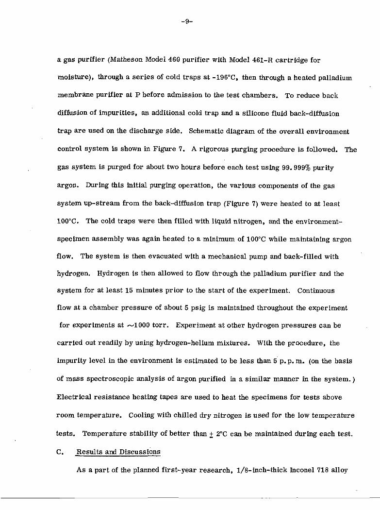
a gas purifier (Matheson Model 460 purifier with Model 461-R cartridge for
moisture), through a series of cold traps at -196°C, then through a heated palladium
membrane purifier at P before admission to the test chambers. To reduce back
diffusion of impurities, an additional cold trap and a silicone fluid back-diffusion
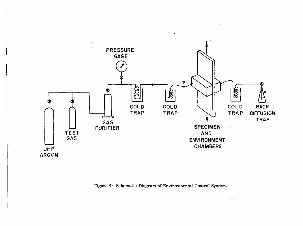
trap are used on the discharge side. Schematic diagram of the overall environment
control system is shown in Figure 7. A rigorous purging procedure is followed. The
gas system is purged for about two hours before each test using 99.999% purity
argon. During this initial purging operation, the various components of the gas
system up-stream from the back-diffusion trap (Figure 7) were heated to at least
100°C. The cold traps were then filled with liquid nitrogen, and the environment-
specimen assembly was again heated to a minimum of 100°C while maintaining argon
flow. The system is then evacuated with a mechanical pump and back-filled with
hydrogen. Hydrogen is then allowed to flow through the palladium purifier and the
system for at least 15 minutes prior to the start of the experiment. Continuous
flow at a chamber pressure of about 5 psig is maintained throughout the experiment
for experiments at —1000 torr. Experiment at other hydrogen pressures can be
carried out readily by using hydrogen-helium mixtures. With the procedure, the
impurity level in the environment is estimated to be less than 5 p. p. m. (on the basis
of mass spectroscopic analysis of argon purified in a similar manner in the system.)
Electrical resistance heating tapes are used to heat the specimens for tests above
room temperature. Cooling with chilled dry nitrogen is used for the low temperature
tests. Temperature stability of better than + 2°C can be maintained during each test.
C. Results and Discussions
As a part of the planned first-year research, 1/8-inch-thick Inconel 718 alloy

-10-
and 1/4- inch- thick 18Ni(200) maraging steel plate specimens are being tested in
dehumidified gaseous hydrogen under a slightly positive pressure of about 5 psig (or,
about 1000 torr) over a range of temperatures from about -60°C to +300°C. Available
results on the two materials will be discussed separately below.
1. Inconel 718 Alloy
Crack growth experiments have been carried out on the Inconel 718 alloy
at about -50, +25 and +300°C. Increasing K levels for the sustained-load crack
growth tests were obtained by increases in the applied load, or by further extension
of the crack by fatigue. By the latter procedure some fatigue crack growth data in
gaseous hydrogen were obtained. The results showed that there was no detectable
crack growth under sustained loading at these temperatures for K levels up to about
i 790 ksi-in. 2 (the lower limit of detectability for crack growth being about 10"' in/sec. ).
Fatigue crack growth data obtained during these tests also show the absence of hydro-
gen effect at room temperature for 1^^ up to 90 ksi-in. 5, at R =
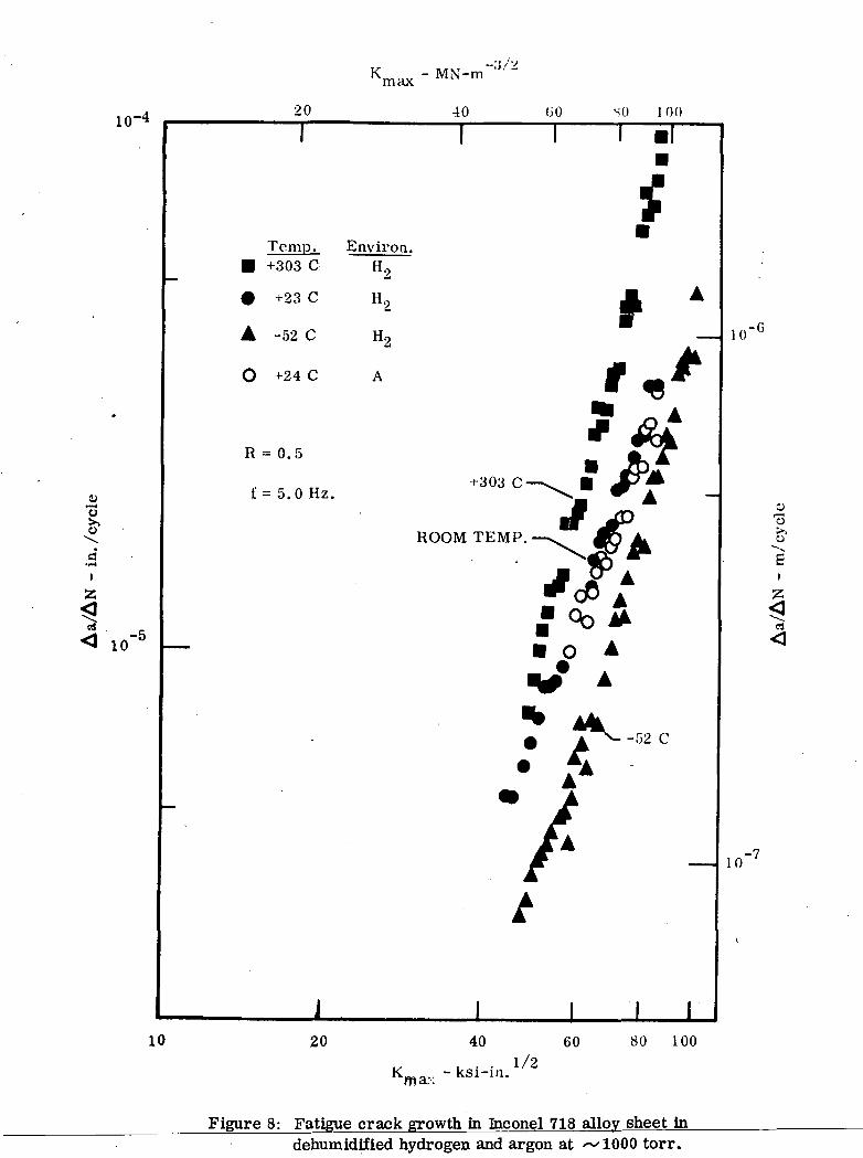
0. 5 and a test frequency of 5. 0 Hz. (Figure 8). These results are consistent with
fatigue test results obtained previously on a 0. 06- inch- thick Inconel 718 alloy sheet
[29]. These results suggest that there is little effect of hydrogen under these condi-
tions of temperature and pressure (~/ 1000 torr). The absence of gaseous hydrogen
embrittlement under these conditions, however, does not preclude the possibility
of embrittlement at other temperatures and pressures. Embrittlement of this alloy
in high pressure hydrogen has been observed by Walter and Chandler [20] using
smooth and notched round tensile specimens. Evaluation of the crack growth charac-
teristics, coupled with surface chemistry studies, at other conditions would be
desirable. Fatigue crack growth has been shown to be a function of temperature

-11-
(see Figure 8) decreasing by about a factor of 3 from +300°C to -50°C. This tempera-
ture dependence is of importance to service performance and needs to be considered
in design.
2. 18Ni(200) Maraging Steel
Because of delays and technical difficulties in the procurement and prepara-
tion of the 18Ni(200) maraging steel, experimental work on this material has just
begun. Modified WOL specimens (Figure 4) are being used in place of the 3-inch-
wide center-cracked specimen (Figure 3) as planned in the original program. Some
preliminary results were obtained on the 3-inch-wide center-cracked specimens.
The results indicate that no detectable crack growth occurred in gaseous hydrogen
(tvlOQQ torr) at room temperature for K levels up to about 70 ksi-inA Crack
growth, however, was observed at about -30°C and exhibited a rate limiting speed
of about 1. 5 x 10~4 in. /sec. This speed is about 1/5 of that for the 18Ni(250)
maraging steel tested at the same temperature, Figure 9. These very preliminary
results suggest that the temperature dependence for hydrogen enhanced crack growth
is a function of alloy composition and/or of strength level, Figure 10 [30]. Addi-
tional experiments to fully characterize the temperature and pressure dependence
of crack growth in hydrogen for this alloy are in progress.
III. HYDROGEN ADSORPTION AND DIFFUSION
A. Experimental Arrangement and Procedure
Hydrogen adsorption and diffusion to metals and alloys are be tog studied
using a hydrogen-deuterium exchange technique. Based on a statistical treatment
of the exchange reactions to which diatomic molecules react with solids containing

-12-
the same kind of atoms [31], the mechanism of adsorption and the diffusion coeffici-i
ents can be determined by following two derived quantities K and W during the
exchange experiment:
[HDL2)"K = "K- [D2](g)[H2](g)
W=2[D2] (g )+[HD] (g ) (4)
)» anc^ tHDl(g) are tne m°lecular fractions of the D2, H2 and HD mole-
cules, respectively, in the gaseous phase at a given time. At equilibrium, the
quantity K assumes the value of 4, and becomes equal to the equilibrium constant.
Deviation of K from this equilibrium value provides a direct measure of the propor-
tion of different possible mechanisms of the exchange, and identification of the likely
process associated with gaseous hydrogen embrittlement [31]. Measurements of
the change in atomic deuterium concentration (W) in the gaseous phase give infor-
mation regarding the extent of hydrogen diffusion into the bulk material and the
relative contribution of this process to crack growth.
An ultrahigh vacuum (UHV) apparatus for the hydrogen deuterium exchange
experiment has been constructed. A schematic diagram of this apparatus is shown
in Figure 11. Ultrahigh vacuum is obtained by cryostatic roughing, followed by
pumping with a titanium sublimation pump and a titanium sputter ion pump. The
total pressures in the apparatus are measured by an ionization gage (low pressures)
and by a Pirani gage (intermediate and high pressures). A quadrupole residual gas
analyzer is used to monitor the D2, H2 and HD components in the gaseous phase
during the exchange experiments through a calibrated capillary. To provide a
-13-
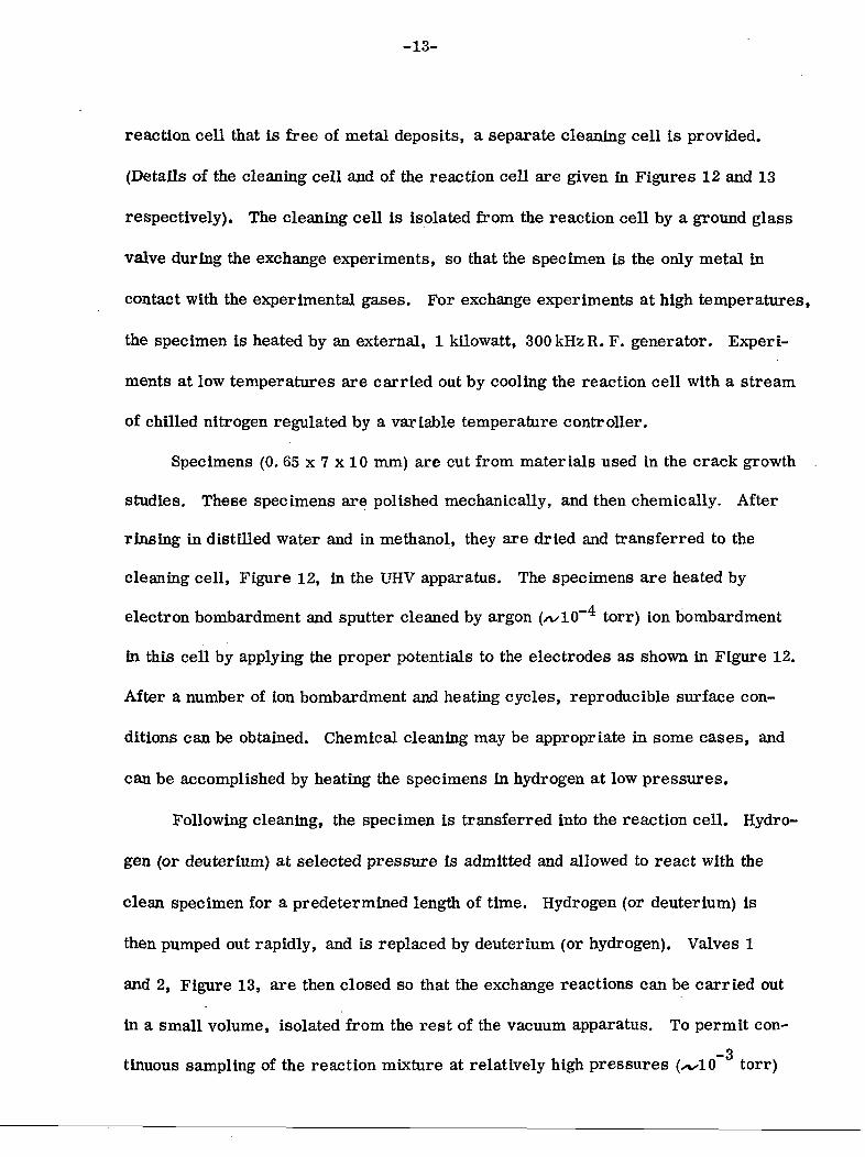
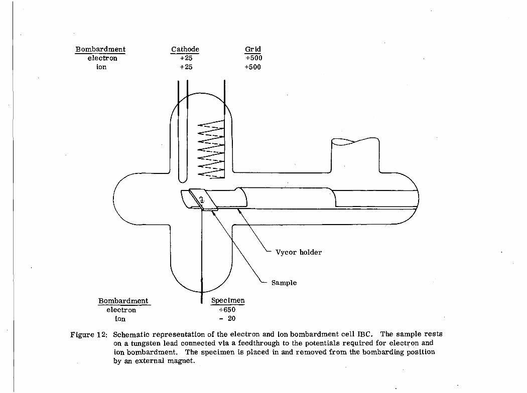
reaction cell that is free of metal deposits, a separate cleaning cell is provided.
(Details of the cleaning cell and of the reaction cell are given in Figures 12 and 13
respectively). The cleaning cell is isolated from the reaction cell by a ground glass
valve during the exchange experiments, so that the specimen is the only metal in
contact with the experimental gases. For exchange experiments at high temperatures,
the specimen is heated by an external, 1 kilowatt, 300 kHzR. F. generator. Experi-
ments at low temperatures are carried out by cooling the reaction cell with a stream
of chilled nitrogen regulated by a variable temperature controller.
Specimens (0. 65 x 7 x 10 mm) are cut from materials used in the crack growth
studies. These specimens are polished mechanically, and then chemically. After
rinsing in distilled water and in methanol, they are dried and transferred to the
cleaning cell, Figure 12, in the UHV apparatus. The specimens are heated by
electron bombardment and sputter cleaned by argon (/vlO torr) ion bombardment
in this cell by applying the proper potentials to the electrodes as shown in Figure 12.
After a number of ion bombardment and heating cycles, reproducible surface con-
ditions can be obtained. Chemical cleaning may be appropriate in some cases, and
can be accomplished by heating the specimens in hydrogen at low pressures.
Following cleaning, the specimen is transferred into the reaction cell. Hydro-
gen (or deuterium) at selected pressure is admitted and allowed to react with the
clean specimen for a predetermined length of time. Hydrogen (or deuterium) is
then pumped out rapidly, and is replaced by deuterium (or hydrogen). Valves 1
and 2, Figure 13, are then closed so that the exchange reactions can be carried out
in a small volume, isolated from the rest of the vacuum apparatus. To permit con-
-3tinuous sampling of the reaction mixture at relatively high pressures (xwlO torr)

-14-
with the quadrupole analyzer, and to prevent contact with the metal walls of the
analyzer, a small amount of the reaction mixture is admitted directly into the ioni-
zation chamber of the analyzer through a calibrated capillary leak, C, Figure 13.
The amounts of deuterium (Do), hydrogen (H2) and the mixed molecules (HD) are
monitored as functions of time to determine the time variation of K and W.
In the apparatus described above, the activity-of a metal surface can be
investigated in three ways:
1. By mass spectrometric monitoring of an exchange reaction between hydro-
gen (H2) and deuterium (D2) molecules catalyzed by the metal surface. This rate
is a measure of the ability of the metal to atomize hydrogen in its surface.
2. By mass-spectrometric monitoring of a replacement reaction in which
hydrogen is placed in the material first and then isothermally replaced by deuterium
from the gas phase. The total rate of production of hydrogen in the gaseous phase
is a measure of the extent of adsorption and diffusion. The rates of appearance of
the individual molecules H2 and HD and of disappearance of D2 from the gas phase
are measures of the mechanism by which hydrogen enters the surface layer.
3. By flash desorption of hydrogen from the metal surfaces. This technique
enables the determination of the total adsorbed amounts and approximate binding
strength of hydrogen to the surface.
B. Materials
The materials studied in the first year were the 18Ni(250) maraging steel,
18Ni(200) maraging steel, and a single crystal of iron cut and polished to expose
the (111) plane. The 18Ni(250) maraging steel was investigated as an additional
material not included in the original proposal. The samples were 0.6 mm thick
rectangular slabs of total surface area of about 1.5 cm2.
-15-
The following pretreatments were employed:
1. The metal surface was cleaned by argon ion bombardment (denoted as AB)
under the conditions specified in section III-A. According to the results of Auger
spectroscopic analyses, the surface composition of the ion bombarded material was
the same as the nominal bulk composition (within the limits of accuracy of Auger
spectroscopy). This cleaning procedure was employed prior to any of the subse-
quent treatments.
2. Some specimens were then surf ace-annealed at 400°C by electron bombard-
ment for 5-10 minutes. This treatment is denoted A (annealed sample); absence
of this treatment is denoted NA (non-annealed sample).
3. Prior to any cleaning procedure, the steel specimens were always heated
to 850°C in vacuo and subsequently cooled to room temperature without aging at
500°C. Experiments on these annealed, non-aged specimens are marked by the
symbol NAG. However, some specimens were aged at 500°C for 3 hrs. after the
first argon ion bombardment, and subsequently ion bombarded again. These speci-
mens are denoted AG (aged).
C. Results and Discussion
The replacement reactions (process #2, page 14) were attempted by loading
othe specimens with deuterium (D2) at 10 torr and 25°C and replacing the gas phase
by hydrogen (H2) at 10~4 torr from a volume of 1. 5 liter. No replacement reactions
were observed at temperatures between -190°C and 200°C. This result indicates
that not much hydrogen was picked up by the materials studied, at least not in excess
of 10-20 layers. Further experiments are in progress at lower pressures of hydro-
gen to pursue the replacement reaction with a greater sensitivity.

-16-
The exchange reactions (process #1, page 14) were then investigated to pro-
vide a measure of the activity of the steel and iron crystal surfaces towards atomiza-q o
tion of hydrogen. The ranges of pressures 10 to 10"^ torr and temperatures
between -190°C and +300°C were investigated. Measurable rates of the exchange
H2/g\ + D 2(g)* I— 2HD(g) were obtained at temperatures between 0°C and 300°C.
The results of the measurements of the total homo molecular rate of exchange (R +
R! + R") for the different materials and treatments are summarized in Table 5. The
experimental material substantiating these data is presented in Appendix I.
The rates (R + R1 + R") are those of overall adsorption, atomization, and
recombination of hydrogen molecules on the given surface, irrespective of the
mechanism by which the surface atomization takes place. These rates are therefore
representative of the ability of the given material to atomize and recomblne hydrogen.
The data In Table 5 demonstrate the following order of chemical activities:
Fe (111) crystal > 18Ni(200) > 18Ni(250)
The effect of pretreatments is such that non-annealed surfaces are more active than
annealed surfaces and that aged specimens are more active than non-aged specimens.
The activation energies for all samples are between 0. 5 and 4. 0 kcal/mole and are
higher on 18Ni(250) specimens than on 18Nl(200) specimens. The kinetic data pre-
sented in Table 5 are based on the Initial rates. The rates themselves are not con-
stant with time as shown in the last column of Table 5, and Indicate some decay of
the surface activity with time. This phenomenon Is most likely caused by hydrogen
self-poisoning of the surface.
The initial rates (R + R1 + R") on the iron crystal (^ 1017 molecules/cm. 2
sec at 25°C and 10 torr) are quite comparable to the adsorption rates of hydrogen

-17-
on polycrystalline iron, obtained by extrapolation of data reported by Chornet and
Coughlin [32]. These authors also determined the activation energy for adsorption
to be 0.5 kcal/mole which is at the lower end of the range of activation energies for
the H2/D2 exchange observed in this work. We can thus tentatively conclude that
the exchange rates are kinetically limited by and coincide with the adsorption rates,
and conversely, that the adsorption rates are determined by the rates of surface
atomization of the impinging hydrogen molecules. The dissociation of the hydrogen
molecules into atoms is the most common mechanism for activation of hydrogen for
chemical reactions, and may be suggested as one possible reason for hydrogen
embrittlement. The hydrogen atoms adsorbed in the vicinity of a crack tip may
weaken the metal-metal bond and cause an enhancement of the crack growth rate
(stress sorption cracking), or may diffuse ahead of the crack tip and form a com-
posite zone whose mechanical cohesion is weaker than that of the hydrogen-free
material. In order to test these possibilities, it is desirable to compare the rates
of hydrogen atom production with the crack growth rates under comparable tempera-
ture and pressure conditions. So far the chemical rates and the crack growth rates
have been obtained at different pressures but the pressure dependence of the crack
growth rates permits tentative comparison to be made. Taking the crack growth
rate of the 18Ni(250) maraging steel to be 10~3 cm/sec in 86 torr hydrogen [30] and
assuming the rate to be proportional to the square root of pressure [30], we obtain
o oa linear rate of 1000 A/sec at 10 torr. If the crack growth rate is determined by
the supply of hydrogen atoms, the rate of formation of the new surface will be given
by the rate of production of hydrogen atoms that can reach the crack tip. Calcula-
tions based on the observed rates of atomization show that hydrogen atoms from the

-18-
region extending to 50 A on both sides of the crack tip would be sufficient to sustaino
the crack growth rate of 1000 A/sec. The rate of transport of the hydrogen atomso
within the 50 A distance would have to be sufficiently high for this mechanism to
operate. On the surface of pure iron, the lateral mobility of hydrogen atoms is
indeed high since the entropy of the adsorbed hydrogen has been found to be close
to the entropy of a two-dimensional monatomic gas [32].
The situation on alloy surfaces which are our main concern may or may not
be different from that on pure iron. The differences may stem from different
chemical composition, structure and texture of the iron and steel surfaces, and may
affect both the reactivity of the surface and the lateral mobility of the hydrogen atoms.
From the comparison of the activities in Table 5, the steel surfaces do not appear
to have components more active than iron itself. In fact, their activities are so
close to that of pure iron that it would seem that the iron alone may be responsible
for their reactivity toward hydrogen. The effects of chemical composition will be
further investigated on steel specimens aged at 400-500°C for 3 hrs. at which
temperatures and times Auger spectroscopy revealed a substantial enrichment of
the surface by titanium and molybdenum.
The effects of texture and surface roughness can be crudely estimated from
the comparison of argon bombarded, non-annealed surfaces with argon bombarded
and annealed surfaces. There is a distinct difference in the reactivities of the non-
annealed and annealed surfaces, although their chemical composition is approximately
the same. The non-annealed surfaces have in average about half order of magnitude
higher activity than the non-annealed surfaces (Table 5). This effect is easily under-
stood in terms of higher activity of atoms displaced from their regular positions,

-19-
increased concentration of vacancies, and generally higher energy content of the
non-annealed, highly perturbed surfaces. The difference hi the activity of the
annealed and non-annealed surfaces is not great, however, and one can expect that
slightly perturbed surfaces will have their activity close to that of the annealed sur-
face. It would of course be desirable to know what kind of surface perturbations
occur at the crack surface, and therefore it is planned to carry out the hydrogen
adsorption and exchange experiments on the actual crack surface which will yield
additional kinetic information for comparison with that presently obtained for pure
iron and steel surfaces cleaned by argon bombardment.
The effects of structure are perhaps reflected in the differences in the activities
of the aged and non-aged specimens of the 18Ni(250) maraging steel (Table 5, rows
6 and 7). The aged specimens exhibit about one order greater activity than the
non-aged specimens indicating a higher reactivity of the aged martensitic structure
over the annealed structure. These results should be compared with crack growth
data on the aged and the annealed maraging steels.
IV. SUMMARY
1. No sustained-load crack growth was observed for the Inconel 718 alloy
in gaseous hydrogen (~-1000 torr) at about -50°C, 25°C and +300°C for stress inten-
sities up to 90 ksi /in. The rate of fatigue crack growth at room temperature,
with R = Kmm/Kmax = 0. 5 and f = 5. 0 Hz, was also unaffected by gaseous hydrogen
(at~1000 torr).
2. Preliminary results on the 18Ni(200) maraging steel indicated that sus-
tained-load crack growth was unaffected by hydrogen (xvxlOOO torr) at room

-20-
temperature, but was affected by hydrogen at about -30°C. The rate limiting speed
was about 1. 5 x 10~4 in. /sec. at -30°C, and was about 1. 5 of that for the 18Ni(250)
maraging steel. These very preliminary results suggest that the rate and temperature
dependence for hydrogen enhanced crack growth is a function of alloy composition
and/or of strength level. Additional experiments are in progress.
3. The rates of hydrogen atomization by the three types of materials investi-
gated are high and probably sufficient to sustain the crack growth through a mechanism
limited by hydrogen atom formation.
4. The differences between the activities of the 18Ni(250), 18Ni(200) and
iron (111) surfaces are small, indicating that either the alloying elements (mainly
nickel) exhibit activity close to that of iron or that iron may be the principal carrier
of the hydrogen activation.
5. Aged specimens are more active for hydrogen atomization than non-aged
specimens.
6. Surface roughness induced by ion bombardment increases the activity of
all materials studied.
7. It appears that prevention of hydrogen embrittlement in maraging steels»
should be sought in adding alloying elements which would poison the catalytic
activity of the surface for hydrogen atomization, or which would act as traps for
hydrogen atoms preventing their surface diffusion. The effects of gaseous poisons
such as C>2> ^O, CS, and CS2 should also be considered if the presence of these
gases can be accepted on technological grounds. The experiments on poisoning of
the steel surfaces by these gases with respect to hydrogen adsorption and exchange
can be carried out hi our present system without modification.

-21- "•• ;
REFERENCES
1. C. Zapffe and C. Sims, AIME Trans. 145, 225 (1941).
2. F. Garofalo, Y. T. Chou,and V. Ambegaokar, Acta Met., J, 504 (1960).
3. B. A. BUby and J. Hewitt, Acta Met. , 10, 587 (1962).
4. A. S. Tetelman, Proceedings - Fundamental Aspects of Stress CorrosionCracking, Natl. Assoc. Corr. Engrs. , Houston, 446 (1969).
5. R. P. Frohmberg, W. J. Barnett, and A. R. Troiano, Trans. ASM, 47,892 (1955).
6. H. H. Johnson, J. G. Morlet,and A. R. Troiano, Trans. TMS-AIME, 212,528 (1958).
7. E. A. Steigerwald, F. W. Schaller, and A. R. Troiano, Trans. TMS-AIME,215, 1048 (1959).
8. A. R. Troiano, Trans. ASM, 52, 54 (1960).
9. N. O. Fetch and P. Stables, Nature, 169. 842 (1952).
10. H. H. Johnson, Proceedings - Fundamental Aspects of Stress CorrosionCracking, Natl. Assoc. Corrosion Engrs., Houston, 439 (1969).
11. R. P. Wei, Intl. J. Fract. Mech., 4, 159 (1968).
12. R. P. Wei, J. Eng'g. Fract. Mech., I, 633 (1970).
13. F. J. Bradshaw and C. Wheeler, RAE Tech. Memo. No. MAT 26 (1968).
14. T. Bloom and A. J. Nicholson, J. List. Metals, J39, 183 (1960).•
15. G. G. Hancock and H. H. Johnson, Trans. TMS-AIME (1966).
16. R. p. Wet and J. D. Landes, Matl. Res. & Std., ASTM, Vol. 9, No. 7, 25(1969).
17. W. A. Spitzig, P. M. Talda, and R. P. Wei, J. Eng'g. Fract. Mech., 1,155 (1968).
18. D. P. Williams and H. G. Nelson, Metallurgical Trans., 1, 63 (1970).
19. H. G. Nelson, D. P. Williams, and A- S, Tetelman, "Embrittlement of aFerrous Alloy in a Partially Dissociated Hydrogen Environment," preprint ofa paper submitted for publication in the Metallurgical Trans. (1970).

-22-
20. R. J. Walter and W. T. Chandler, "Effect of High-Pressure Hydrogen onMetals," paper presented at the Symposium on Effects of Gaseous Hydrogenon Metals, 1968, Materials Eng'g. Congress, Detroit, Mich., 13-17 October1968.
21. R. P. Wei, "The Effects of Temperature and Environment on SubcriticalCrack Growth," presented at the WESTEC Conference (1972); Rept. IFSM-72-14,Lehigh University (April 1972).
22. R. A. Oriani, Proceedings - Fundamental Aspects of Stress CorrosionCracking, Natl. Assoc. Corr. Engrs., Houston, 32 (1969).
23. D. S. Dabkowski, L. F. Porter, and G. E. Loveday, "Evaluation of VacuumInduction Melted 18Ni(180) and 18Ni(250) Maraging Steels," Rept. 39. 018-007(3),Applied Research Laboratory, U. S. Steel Corporation, January 1, 1967.
24. W. F. Brown, Jr. and J. E. Srawley, ASTM STP 410 (1966).
25. M. Isida, "Crack Tip Stress Intensity Factors for the Tension of an Eccen-trically Cracked Strip," Lehigh University, Dept. of Mechanics Report (1965).
26. W. G. Clark, Jr., private communication.
27. J. D. Landes, "Kinetics of Subcritical-Crack Growth and Deformation in aHigh-Strength Steel, " Ph. D. Dissertation, Lehigh University, (1970).
28. Che-Yu Li and R. P. Wei, Mat'l. Res. and Stds., ASTM, j», 392 (1966).
29. R. P. Wei, unpublished results.
30. S. J. Hudak, Jr. and R. P. Wei, "The Kinetics of Hydrogen Enhanced CrackGrowth in High Strength Steels," to be published.
31. K. Kller, J. Novakova, and P. Jiru, J. Catalysis 2, 479 (1963).
32. E. ChornetandR. W. Coughlin, J. Catalysis 27, 246 (1972).
-23-
APPENDIX I
The data on the time dependences of the concentrations of gaseous H2>
and HD molecules over various metal specimens investigated are given herein.
The relative concentrations of the individual molecules at any given time are repre-
sented as molecular fractions, for example 777-; — rTJT^ , , is the relative con-ing + LnJJj + IJJ2J
centration of the HD molecules. The reduced concentrations are *
HDK = r- — T is a measure of the mixing entropy in the gaseous pahse, and is also
IH2J ID2J
plotted in some of the graphs. Its time dependence is a measure of the approach of
me system metal-hydrogen to the equilibrium where K has a maximum value of 4.
The data are presented in three separate sets, one for each material studied.
A. 18Ni(250) Maraging Steel
1. NAG-AB-NA (non-aged, argon bombarded, non-annealed) specimen.
The time dependences of the relative concentrations of H2, HD, and D2
at pressures around 10~2 torr are given for the individual temperature runs in
Figures 14-18. The variations in the pressure from one experiment to another
were slight and did not significantly affect the measured rates. Also plotted in»
Figures 14-18 is the function K = [HD]2/[H2] . [D21. The rates of exchange are
quantitatively evaluated by plotting the logarithms of the reduced concentrations
of the D2 and HD molecules against time. The slopes of the lines drawn through
the experimental points in these coordinates give the rates of homomolecular
exchange, — (R + R1 + R"), where a = [H2] + [HD] + [D2]. An experimental check3.
for the validity of this treatment is that the slopes for the reduced concentrations
-24-
of H2, HD, and D2 coiBcide. Figures 19-23 show the replotted data of Figures
14-18 for the reduced concentrations of the D2 and HD molecules. The concentra-
tions of D2 and HD follow roughly the same lines, demonstrating that the true rates
(R + R1 + R") are measured. The temperature dependence of the rates (R + R1 + R")
is shown in Figure 24. The maximum exhibited on this temperature dependence was
not found with other preparations of the 18Ni(250) mar aging steel and is not under-
stood at the present moment.
2. AG-AB-NA (aged, argon bombarded, non-annealed) specimen.
The rates of the H2/D2 exchange are represented as the time variations
of the logarithms of the reduced concentrations of HD and D2 in Figures 25-32
The temperatures and pressures at which these experiments were carried out
are given in the figure captions.
The temperature dependence of the rates is presented hi Figure 33, together
with the temperature dependence on the AG-AB-A 18Ni(250) maraging steel.
3. AG-AB-A (aged, argon bombarded, non-annealed) specimen.
The rates of the H2/D2 exchange are represented as the variations of the
logarithms of the reduced concentrations of HD and D2 in Figures 34-40. The
temperatures and pressures at which these experiments were carried out are again
given in the figure captions.
The temperature dependence of the rates is presented in Figure 33, together
with the temperature dependence on the AG-AB-NA 18Ni(250) maraging steel.
B. 18Ni(200) Maraging Steel
1. AG-AB-NA (aged, argon bombarded, non-annealed) specimen.
The rates of the H2/D2 exchange are again represented as the time

-25-
dependences of the logarithm of the reduced concentrations of HD and D^ in
Figures 41-45, with temperatures and pressures given in the figure captions.
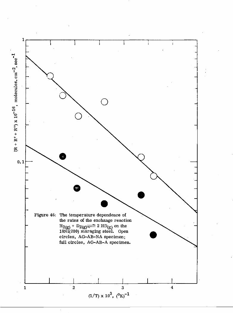
The temperature dependence of the rates is represented in Figure 46, together
with the temperature dependence of the exchange rates on the AG-AB-A 18Ni(200)
mar aging steel.
2. AG-AB-A (aged, argon bombarded, non-annealed) specimen.
The rates of the H2/D2 exchange are again represented as the time dependences
of the logarithms of the reduced concentrations of HD and D- in Figures 47-51, with
temperatures and pressures given in the figure captions.
The temperature dependence of the rates is represented in Figure 46, along
with the temperature dependence of the rates on the AG-AB-NA 18Ni(200) maraging
steel.
Fe (111) Single Crystal
The iron single crystal was cut along the (111) plane, mechanically and
chemically polished, and cleaned in the ultrahigh vacuum system by repeated
argon ion and electron bombardments. The final treatment was electron bombard-
ment annealing at 750-800°C. By this procedure, the (111) crystallographic orien-
tation of iron crystal is restored. The data on iron crystal serve as a reference
for comparison of the various ferrous alloys. The rates of the H2/D2 exchange
•
on Fe (111) were the highest observed. The time dependence of the logarithm of
the reduced concentrations of HD and D2 are represented in Figures 52-54. The data
on activation energies are not available since time limits permitted the experiments
to be done only at room temperatures.

-26-
The Time Dependence of the Rates
All rates measured in this work decayed with time by varying factors of
2-5 in 10 minutes (Table 5). The time dependence will certainly affect the slopes
of the logarithms of the reduced concentrations vs. time, and therefore the calcu-
lated rates (R + R1 + R") are time averages over the duration of the experiment. It
is unlikely that the time dependence is caused by poisoning of the surface by residual
gases other than hydrogen since the clean surfaces retain their activity when kept
in vacuum without the presence of hydrogen. The poisoning of the surface by the
diffusion of Impurities from the bulk Is also unlikely since the time effects are
little temperature dependent and since no time changes in surface chemical compo-
sition were observed by Auger spectroscopy at the temperatures of these experi-
ments. A physical relaxation of the surface Is ruled out on the annealed specimens
which still show a similar time dependence as the non-annealed specimens. The
remaining possibility is self-poisoning of the surface by hydrogen. At the present
time this seems to be the best explanation of the time decay of the activity. Hydro-
gen may exist in the surface in various forms, one or more of which may be formed
by a slow reaction. The question of time dependence of the reaction rates will be
given further attention in the next year of the project.

TABLE 1
CHEMICAL COMPOSITION AND HEAT TREATMENTFOR INCONEL 718 ALLOY SHEET
Chemical Composition, Weight Percent(ESfCO Huntington Alloy Products Div. Heat No. HT94B1ES)
C
Mn
Si
P
S
Ni
Cr
Mo
Cu
Cb+Ta
Ti
Al
Co
B
Fe
AMS 5596 Cmin. max.
0.10
0. 35
0. 35
0.015
0.015
50.0 55.0
17.0 21.0
2.8 3.3
0.1
5.0 5.5
0.65 1.15
0.4 0.8
1. 0
Balance
Supplier'sAnalysis
0.05
0.07
0.19
0.009
0.007
53.81
18.40
2.96
0.04
5.19
1.00
0.58
0.03
0.0028
17.65
CheckAnalysis
0.03
0.40
0.17
0.007
0.004
54.2
17.9
2.94
0.05
3.68
1.00
0.43
0.12
ND*
ND*(~19. 1)
*ND - Not Determined
Heat Treatment
Solution Anneal - 1800°F, 1 hour + Air Cool
Age - 1325°F, 8 hours + Furnace Cool to 1150°F + Holdat 1150°F for total aging time of 18 hours + Air Cool

TABLE 2
Huntlngton Alloy(Supplier)
AMS 5596C
Tensile Properties of Inconel 718 Sheet(Heat No. HT94B1ES)
Tensile StrengthSource Orientation ksl
Lehigh LongitudinalUniversity
(Average)
Transverse
203.4205.1202.8203.8
200.5201.9201.7201.4
Yield Strengthksi
166.8168.5166.2167.2
167.4168.4168.5168.1
Elongationin 2 in.percent
18.018.017.517.8
17.017.017.017.0
Transverse
Transverse
202.0
180.0 (min.)
177.0 18.0
150.0 (mln.) 12 (min.)

TABLE 3
CHEMICAL COMPOSITION AND HEAT TREATMENTFOR 18Ni(200) MARAGESfG STEEL PLATE
Chemical Composition, Weight Percent(U.S.
cMn
Si
P
S
Ni
Co
Mo
Ti
Al (sol. )
N
O
Fe
Steel Corporation Heat No.
Supplier'sAnalysis [ ]
0.002
<0.02
0.003
0.003
0.007
17.50
7.60
2.93
0.20
0.007
0.004
0.0011
Balance
L-50446)
CheckAnalysis^
ND*
ND
ND
ND
ND
17.89
7.50
2.75
0.18
ND
ND
ND
Balance
* ND - Not Determined
Heat Treatment
Solution Anneal - 1650°F, 1/2 hour + Air Cool
Re-solution Anneal - 1500°F, 1/2 hour + Water Quench
Age - 900°F, 16 hours + Water Quench

TABLE 4
Tensile Properties of 18Ni(200) Maraging Steel Plate(U. S. Steel Heat No. L-50446)
ElongationTensile Strength Yield Strength in 2 in.
Orientation ksi ksi percent
Longitudinal 193.1 185.7 13.0192.8 185.5 13.0193.2 185.0 12.5
(Average) 193.0 185.4 12.8

TABLE 5
Summary of the Rates, Activation Energies, and Time Dependencesof the H2/D2 Exchange on 18 Ni (250) Maraging Steel,
18 Ni (200) Maraging Steel, and Iron Crystal of (111) Orientation
Material
Iron singlecrystal, (111) plane
18 Ni 200maraging steel
18 Ni 250maraging steel
Treatment3"
AB-A (750°C)
AG-AB-A
AG-AB-NA
AG-AB-A
AG-AB-NA
NAG-AB-NA
Rate of homomolecularexchange R + R' + R"
at 25°C b
1 x 10¹⁷
5 x 10¹⁶
1 x 1017
i x 1016
4 x 10¹⁶
4. 5 x 10¹⁵
EA (kcal/mole)
0.55
1.0
2.25
1.2
1. 0-4. 0
Time Dependence
1017-»4 x 10¹⁶ in 10 min
5 x 10¹⁶->1 x 10¹⁶ in 10 min
3 x 10¹⁶-»1016 in 10 min (200°C)1. 5 x 10¹⁶->6 x 10¹⁵ in 10 min (100°C)
AG = aged, NAG = non-aged, AB = argon bombarded, A = annealed at 700 - 800°C after argon bombardment,NA = non-annealed.
Rates are in molecules/cm2 sec. Homomolecular exchange is the reaction H2/g\ + D2/g\T— 2HD, . catalyzed by thesurface.

1.000Diam.
<N
1.00
"A" "B"
oin
W = 3.000
oo
Note: "A" = "B" + 0. 001
Figure 1: SEN Fracture Toughness Test Specimen

»H <N eoI I I
EH H H
n o <
eo -So i
IK
<N H
oM
rt <O PH
O
Ooeo
oo
OO
H.LMOHD HOVHO
°X 1 ix « §\ g 8
X., CO
^S>vx^^ a
. 1 \<
iH 0] CO.
1 1 1
a o < -
3 0
.1
0.2
0
.3C
RA
CK
GR
OW
TH
(A
a) -
in
.
0 0 0 0o o • oeO (N rH
•in/ isii - 30NVXSIS3H HiAVOHO HOVHO
Figure 2: Crack growth resistance curves for 1/8-inch-thick Inconel 718allnv shpp.t /solution annealed -and aered^

0.40
-\p— rii ! ii-nii I"A" • "B
NOTCH DETAIL
Note: "A" = "B" + 0. 001
1. 000 Diam.
Figure 3: Center-Cracked Crack Growth Test Specimen

0.55
0.55
a0 = 0. 60
W = 2. 06
300
ooo
ooo
IIa
Figure 4: Modified Wedge-Opening-Load (WOL) Specimen

1.40
1.30
1.20
I 1.10
o0,
•a
0.80
0.70
0.600.00
O Specimen S3-CAL [ I = 2,1 amp., Vr = 443. 2 v v at a = 0. 602 In. ]
__ A Specimen S4-CAL [ I = 3. 3 amp., Vr = 708. 2 \i v at a = 0. 602 In. ]
Figure 5: Calibration curve for 2. 06-uichwide modified WOL specimens.
I0.04 0.08 0.12 0.16 0.20 0.24
v-vr/v0.28 0.32 0.36 0 40 0.44 0.48

(b)
(a)
Figure G: (a) Environment chamber and load train for modified WOL specimens(both covers removed); (b) close-up of environment chamber andspecimen.
TESTGAS
UHPARGON
PRESSUREGAGE
-H-
COLDTRAP
GASPURIFIER
COLDTRAP
COLDTRAP
BACKDIFFUSION
TRAP
SPECIMENAND
ENVIRONMENTCHAMBERS
Figure 7: Schematic Diagram of Environmental Control System.
K m a v - MN-mmax
10-420 40 GO SO 100
0)13
d•f-t
25
• 5< 10'5
\
tTemp.
• +303 C
• ^23 C
A -52 C
O +24 C
Environ.Ho
H
A
10~G
f - 5 . 0 H » .
20
ROOM TEMP. >o
"g
ca
-52 C
ID'7
40 60 80 100
Figure 8: Fatigue crack growth in Inconel 718 alloy sheet indehumidified hydrogen and argon at ~1000 torr.

10-3
uoen
atTJ
10-4
10 20
K - 1VLN -m
:*()
18Ni(250) MARAGING STEEL
18Ni(200) MARAGING STEEL
A J A>^i
A
10-4
10~
OS•a
10.-6
10 20 40
K - ksi-in. 1/2
60
Figure 9: Hydrogen-enhanced subcritical crack growth at about -

40 20
10-3
oo>w
c
I
rt-a
10-4
-1
Tcmpevaluvi' - < '
0 -20 -40
1 1
3.0
I
18Ni(2f»0) MARAGDs'C; STKKL
$\
/^
I I
I I
\
I It
3.8 4.2 4.6
10~a
rt•o
5.0
Figure 10: Effect of temperature on stage II cruek growth at ^1000 torr.

CSP
Figure 11: Block diagram of the UHV system for exchange measurements. Framedpart is an all-glass apparatus with magnetically operated glass ball-to-socket valves 1, 2 and 3; ion and electron bombardment cell IBC; ioniza-tlon gauge IG and Plranl gauge P as pressure sensors; reaction cell RC;and calibrated leak C. The sputter ion pump IP is a Varian 50 Is"1 model,used conjointly with an air cooled 50 ls~l Varian titanium sublimationpump TSP; the cryosorbent, CSP, uses Llnde Molecular Sieve 13X; thebellow valves are Granvllle- Phillips Type C metal valves; and a Varianquadrupole residual gas analyzer (QRGA) is used to monitor the exchangeexperiments.
Bombardmentelectron
ion
Cathode+25+25
Grid+500+500
f \
I
Bombardmentelectron
ion
\Vycor holder
Sample
Specimen+650- 20
Figure 12: Schematic representation of the electron and ion bombardment cell EEC. The sample restson a tungsten lead connected via a feedthrough to the potentials required for electron andion bombardment. The specimen is placed in and removed from the bombarding positionby an external magnet.

Graded Seal
Vycor6 mm Pyrex Sample
To Pumps
Figure 13: Arrangement between the reaction cell and the quadrupole. The calibratedconductance is a 0. 002 inch capillary mounted on a Pyrex envelope. Thereaction products reach the ionization chamber of the quadrupole via a6 mm o. d. Pyrex tubing.

0.8
0.7
Figure 14: The time course of the concentrations of the H2 (Q)' HD ((and D£ (0) molecules over the ion-bombarded 18Ni(250)maraging steel at 1. 4 x 10~2 torr and 0°C. The time dependence of the function K is given as a dashed line.
0.6
a<BO
O
cSI-H0)
0.5
0.4
0.3
0.2
0.1
K
12

T T T T T T T T
0.8
0.7
Figure 15: The time course of the concentrations of the H2 (Q)» HD ((J)D2 (0) molecules over the ion-bombarded 18Ni(250) maraging steelat 7.4 x 10~3 torr and 25°C. The time dependence of the function Kis given as a dashed line.
§
<uo§o
i-H(U
0.6
0.5
0.4 —
0.1
6 7time (min)
10 11
K

0.8 — Figure 16: The time course of the con-centrations of the H£ (Q)» HD ((J)» and
molecules over the ion-bombarded18Ni(250) maraging steel at 8. 8 x 10~3
torr and 100°C. The time dependence ofthe function K is given as a dashed line.
K
6 7time (min)
12

§
O
§O
0>
«•s
1 1 1 1 1 1 I I 1 1 10.8r-
0.1
Figure 17: The time dependence of the con-centrations of the H£ (Q)» HD ((J)> and D2(A) molecules over the ion-bombarded18Ni(250) maraging steel at 1. 0 x 1(T2 torrand 200°C. The time dependence of the func-tion K is given as a dashed line.
K
6 7time (min)
10 11 12

Figure 18: The time dependence of the concentrations of the H2 (Q)» HD ((f)» and
D2 (0) molecules over the ion-bombarded 18N 1(250) mar aging steel at9. 9 x 10~3 torr and 300°C. The time dependence of the function K is givenas a dashed line.
6 7time (mtn)
.9
.8
.7
.6
§3I0)
I
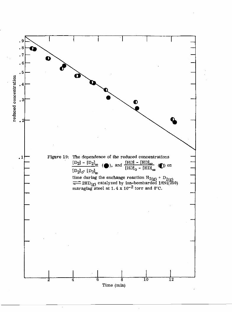
.1 — Figure 19: The dependence of the reduced concentrations
[P2l - ) and1
(C»on
time during the exchange reaction H2/g\ + D2(g)^=^2HD/g\ catalyzed by ion-bombarded 18Ni(250)maraging steel at 1.4 x 10~2 torr and 0°C.
6 8Time (min)
10 12
"3 .4 —
goo•acu§
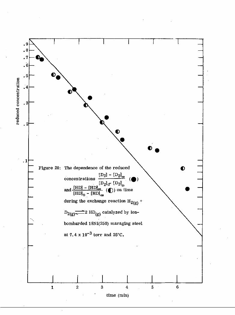
Figure 20: The dependence of the reduced
and [HD] "[HD]0 - [HD]^
during the exchange reaction
2 HD/_v catalyzed by ion-
bombarded 18Ni(250) maraging steel
at 7.4 x 10~3 torr and 25°C.
time (mm)
and
on time during the[HP] - [HDL,HD]0 - [HD],
exchange reaction H2(g) + D2(g)** ^"^{g)
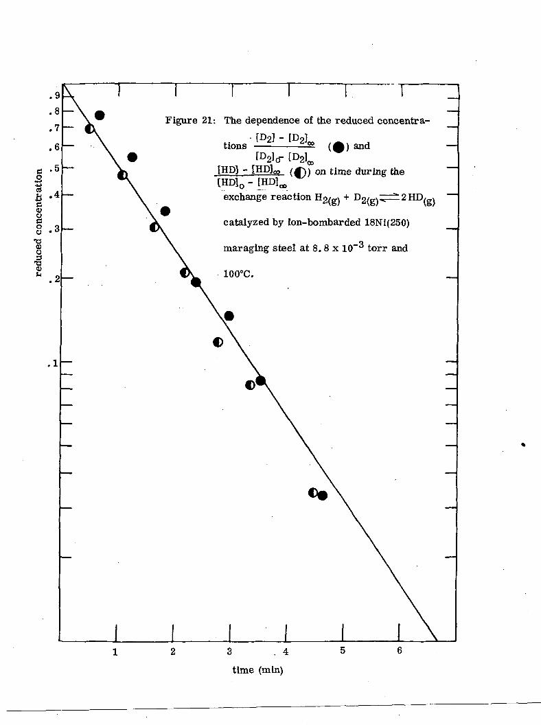
catalyzed by ion-bombarded 18N 1(250)
mar aging steel at 8.8 x 10~3 torr and
100°C.
time (min)

Figure 22: The dependence of the reduced concentrations
time during the exchange reaction
HD/g\ catalyzed by ion-bombarded
18Ni(250) maraging steel at 1. 0 x 10~2 torr
and 200°C.

.9
.8
.7
.6
.5
rt 4ro>
1.3u
•a<D.2
.1Figure 23: The dependence of the reduced concentrations
[HP] - [HDU ^(•>• and [HD]0 - [HDJ^ (O>
on time during the exchange reaction H2/g.v +
r>p/ x——=» 2 HD/p-\ catalyzed by ion-bombarded**\&/ \&/
18Ni(250) maraging steel at 9. 9 x 10~3 torr
and 300°C.
6 8
time (rain)
10 12

o8 8
S fto 6•
CQ
OrH
X
K+
6.
1. OxlO"2 torrV-i 8. 8 x 10"3 torr
7.4xlO~3 torr
1.4x 10~2 torr
Figure 24: The temperature dependence of the rates of theexchange reaction H£/g\ + D£/g\^±2 HD/g\ onion-bombarded 18Ni(250) maraging steel. Thepressures are given as labels.

0.01
Figure 25: The dependence of the reduced concentrations[D2] - [02k .^, [HP] - [HDlco
'V'1 n [HD]0 - [HDl^j ((J) on
time during the exchange reaction ^2(s) +
D2/ffy^^2 HD,ffx catalyzed by AG-AB-NA 18Ni(250)\o/ \o/
maraging steel at 9.4 x 10~3 torr and 0°C.
1 L.2 3
time (mln)

[HD]0 - [HD]{
Figure 26: The dependence of the reduced concentrations
[HP] - [HDL,(Cl)
on time during the exchange reaction
D2/g\^=^2 HD/g) catalyzed by AG-AB-NA
18Ni(250) maraging steel at 8. 3 x 10~3 torr
and 0°C.
IS 0.1g
"8
0.01 —
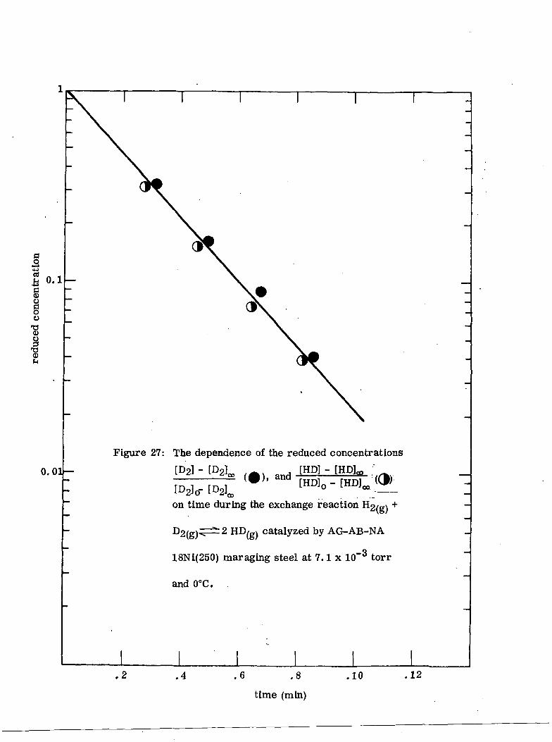
Figure 27: The dependence of the reduced concentrations
[D21 - P2 v [HP] -
[D2]0- [D^
on time during the exchange reaction H-2(e)
catalyzed by AG-AB-NA
18Ni(250) maraging steel at 7.1 x 10~3 torr
and 0°C.
.4 .6 .8
time (min)
.10 .12

I IFigure 28: The dependence of the reduced concentrations
on time during the exchange reaction H2/g\ +
D2/g\T—^ 2 HD /gv catalyzed by AG-AB-NA
18Ni(250) maraging steel at 8.4 x 10~3 torr
and
,8 1.2
time (min)

§••
3
<0
§o^I
I I I ' I
Figure 29: The dependence of the reduced concentrations
[HD] - [HD[HD]0 - [HD?^ .
on time during the exchange reaction
2 HD/_v catalyzed by AG-AB-NA
18Nl(250) maraglng steel at 9.1 x 10~3 torr
and 23°C.
0.01 —
time (min)

0.11
IIoo•a<o
Figure 30: The dependence of the reduced concentrations
[HP] - [HDL, ,^.and
[HD]0 - [HDL
on time during the exchange reaction H2/g\ +
D2, ,^±2 HD{g) catalyzed by AG-AB-NA
18Ni(250) maraglng steel at 8. 8 x 10~3 torr
23°C.
0.01
3 4
time (min)

0.1 —
•o•otJ<0
I4)
Figure 31: The dependence of the reduced concentrations[HP] -jHDlo,
on time during the exchange reaction
D2/g)^=^2 HD/gv catalyzed by AG-AB-NA
18N 1(250) maraglng steel at 10. 3 x 10~3 torr
and 200°C.
.2 .4 6 .8
time (min)
1.0 1.2

\-
0.1
IiO
3
•8
0.01
Figure 32: The dependence of the reduced concentrations[HD] -
on time during the exchange reaction
D2/ffv^=^ 2 HD/gv catalyzed by AG-AB-NA
18N 1(250) maraglng steel at 10.7 x 10~3 torr
and 300°C.
time (mln)

o0)CD
<MIao
»030)
3O
t-rH
- Of-V
fc
K
0.1
Figure 33: The temperature dependence of the rates ofthe exchange reaction H2(g) + D2(g)^^2 HD^on the 18Ni(250) maraglng steeL Open circles,AG-AB-NA specimen; full circles, AG-AB-Aspecimen.
(1/T) x 103,

0.1
§3-a§§o
•8IQ>
0.01
Figure 34: The dependence of the reduced concentrations
[HD]0 -
on time during the exchange reaction Ho,_v +
Dr
18Ni(250) maraging steel at 12. 3 x 10~3 torr
23°C.
! 2 HD, » catalyzed by AG-AB-A
time (min)

0.1
§
00)
o0
•8§•8
'T
0.01
Figure 35: The dependence of the reduced concentrations
(-) and tHDl - [HDL.' ' •
on time during the exchange reaction
D2/g\^^ 2 HD,g) catalyzed by AG-AB-A
18Nl(250) maraglng steel at 12. 9 x 10~3 torr
and 100°C.
3 4
time (mui)

0.1
0.01
Figure 36: The dependence of the reduced concentrations
P2l - [D2L (-) and tHDl - [HP].,
on time during the exchange reaction
n2feV-"^ 2 HD(e) catalyzed by AG-AB-A
18Ni(250) maraging steel at 9.8 x 10~3 torr
and 100°C.
3 4
time (mln)

cd-fa
Io
•8o0)f-l
0.1
0.01
Figure 37: The dependence of the reduced concentrations
CD
on time during the exchange reaction H2/ff\ +
Dnx-y^^ 2 HD, , catalyzed by AG-AB-A\o/ vo/
18Ni(250) maraging steel at 10. 3 x 10~3 torr
and 100°C.
3 4
time (min)

0.1
ah§o
•a<o
0.01
Figure 38: The dependence of the reduced concentrations•l ')2] ~ f n 9 l ^ , [HP] - [HD]m
f I J , , ] - i i M ° (0)> and r-HD]0 - [HOI" <d>" ' • ' * - on ' ^_
on time during the exchange reaction H2/_v +
D2/_v^z± 2 HD/_v catalyzed by AG-AB-A\o/ \o/ ,
18Nl(250) maraglng steel at 10.5 x 10"3 torr
and 200°C.
2
tlm (min)

0.1
tj.b
§o
I0)
0.01
Figure 39: The dependence of the reduced concentrations
> 'i .• IHDJ°
on time during the exchange reaction
D2/g\T~^2 HD,gv catalyzed by AG-AB-A
18Ni(250) maraging steel at 12. 6 x 10"3 torr
and 300°C.
.2 .4 .6 .8
time (min)
1.0 1.2

4-0- The dependence of the reduced concentrations
:
[D2]0-on time during the exchange reaction H2/g\ +
n - 2 HD/0., catalyzed by AG-AB-A2(g)"^ ie^
~3l8Ni(250) maraging steel at 12.7 x 10~ torr
and 400°C.
0.01^

o.i
c.2•uajha
oo
1i
0.01Figure 41: The dependence of the reduced concentrations
[HP] -
on time during the exchange reaction
D2/g)TT^ 2 HD/g^ catalyzed by AG-NA-A
18Ni(200) maraging steel at 12.1 x 10~3 torr
and 0°C.
.2 .4 .6 .8time (min)
1.0 1.2

0.1
•g
O
§O
T)0)
§
"8
o.oi
Figure 42: The dependence of the reduced concentrations
[D21- [D ,- . [HD]-[HDU ;. '[D2]0-
on time during the exchange reaction
HD(g) by AG-NA-A
18Ni(200) maraging steel at 9.5 x 10~3 torr
and 25°C.
.2 .4
time (min)
.6

0.1
bd<oo§o
0>
0.01
Figure 43: The dependence of the reduced concentrations
UM, ,.,, and IM.-
on time during the exchange reaction
- 2 HD (g) by AG-NA-A
~3!8Ni(200) maraging steel at 14. 6 x 10~ torr
and 100°C.
.1 .2 .4
time (min)
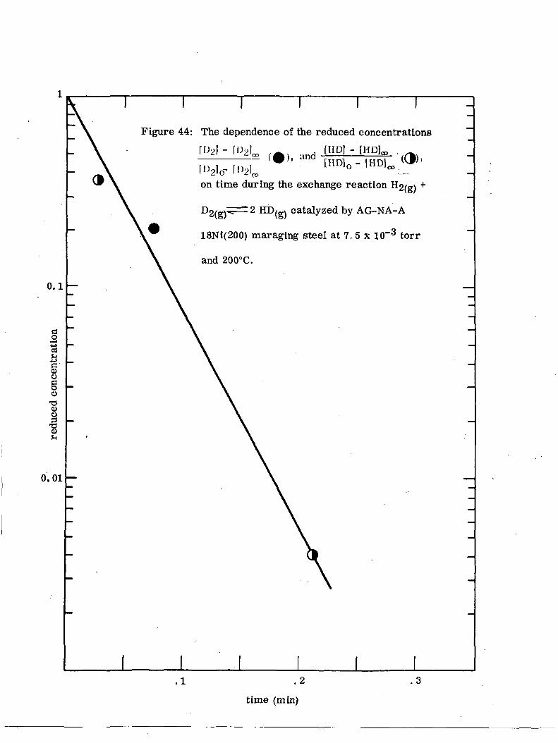
[HD]0 - [HD]^
on time during the exchange reaction HO,_» +
catalyzed by AG-NA-A
18NI(200) maraging steel at 7. 5 x 10"3 torr
and 200°C.
time (min)
0.01 -

Figure 45: The dependence of the reduced concentrations
0.1
-fa§
oo
I0)
0.01
on time during the exchange reaction
D2/gv^=±2 HD/gv catalyzed by AG-NA-A
18Ni(200) maraglng steel at 12. 1 x 10~3 torr
and 300°C.
.1 .2
time (mm)
.3
o<oCQ
CQ0
•3o<0
I— Ioa O
to
K
£
0.1
Figure 46: The temperature dependence ofthe rates of the exchange reactionH2(g) 2 HD(g) on tne
18Ni(200) maraging steel. Opencircles, AG-AB-NA specimen;full circles, AG-AB-A specimen.
(1/T) x 103, (°K)~l

0.1
ctf
I<u8oo
T3CD
I0
0.01
Figure 47: The dependence of the reduced concentrations[HP] - [HD]m
[HD]0 - [HD]^ '<CP
on time during the exchange reaction
,_v catalyzed by AG-AB-A
"318Ni(200) maraging steel at 13. 9 x 10" torr
and 0°C.
time (mln)

0.1
§ogo
730>
I
0.01
Figure 48: The dependence of the reduced concentrations
[HP] -'(3)[HD]0 - [HD]^
on time during the exchange reaction
D2, x^i±2 HD/g.x catalyzed by AG-AB-Aio/ \o/
t
18Ni(200) maraging steel at 14. 6 x 10~3 torr
and 25°C.
.2 .4 .6 .8
time (min)
1.0 1.2

I I
0.1
Io
"8
o.oi
Figure 49: The dependence of the reduced concentrations
[HP] - [HD]m fc[HD]0 - [HD]^1^
on time during the exchange reaction H2/g\ +
D2/o.x^^2 HD,_x catalyzed by AG-AB-A\o/ \&/
18Ni(200) maraging steel at 14. 0 x 10~3 torr
and 100°C.
.2 .4 .6 .8
time (min)
1.0 1.2

0.1
§o
•8o-30>
0.01
Figure 50: The dependence of the reduced concentrations
[HP] -[HD]0 -
on time during the exchange reaction H2/g\ +
y AG-AB-A
18Ni(200) maraging steel at 14. 6 x 10~3 torr
and 200°C.
I I.2 .4 .6
time (min)
.8 1.0 1.2

0.1
§
<oo
o730)O
-gO)
T T T T
Figure 51: The dependence of the reduced concentrations
[HP] -[HD]0 -
on time during the exchange reaction H2/ff\ +
D2/g^r± 2 HD,_v catalyzed by AG-AB-A
18Ni(200) maraging steel at 14. 1 x 10~3 torr
and 300°C.
0.01
.4 .6 .8
time (min)
1.0 1.2

0.1
§33CSI0)§o
•go3•o0>S-t
0.01
Figure 52: The dependence of the reduced concentrations
[HP] - [HDL, '//fr}-[HD]0 - [HD]^ ^
on time during the exchange reaction H2/g\ +
P2(g)^~^2 HD(g) catalyzed by AB-A Fe (111)
18Ni(200) maraging steel at 13. 5 x 10~3 torr
and 23°C.
.2 .3 .4
time (min)
.5 .6

0.1
I•8.fa§oo•oa)u
0.01
Figure 53: The dependence of the reduced concentrations
[HP] - [HD]m ((>)
[HD]0 - [HD]^ IVP'on time during the exchange reaction H2/g\ +
D2(g^^^2 HD^ catalyzed by AB-A Fe (111)
18Nl(200) maraglng steel at 11. 6 x 10~3 torr
and 23°C.
.1 .2 ,3 .4
time (mln)
.5 .6 .7

0.1
IIo
-s0)
0.01
Figure 54: The dependence of the reduced concentrations
[HP] - [HDL, '[HD]0- [HD]^ ^
on time during the exchange reaction H2/g\ +
D2/g\^^2 HD/gv catalyzed by AB-A Fe (111)
18Ni(200) maraging steel at 15. 8 x 10~3 torr
and 23°C.
.6 .8
time (min)
1.0 1.2