Led Tv Light
28
MAJOR UPDATE: Hey Guys! A lot of things have changed since I began my project and I didn't expect so many ideas, comments and improvements. Because it is much easier to build an Ambilight than in my instruction, I decided to update my instructable. First of all, there are, of course, many other solutions out there. Checkout this link, it's easy and really cool: http://hackaday.com/2011/10/05/adalight-ladyadas-ambilight/ THIS instructable is not up to date. If you want to find out about my new approach of building a 30 channel ambilight just search for my other instructable dealing with this topic or click this link: http://www.instructables.com/id/30-channel-LED-RGB-Ambilight-Clone/ (http://www.instructables.com/id/30-channel-LED-RGB-Ambilight-Clone/) Step 1: Java Microcontroller LED TV Ambient Light Recommendations (http://cdn.instructables.com/FPT/DOE9/GKQ3D7ZY/FPTDOE9GKQ3D7ZY.LARGE.jpg) About This Instructable Posted: Mar 1, 2011 License: 30,499 views 36 favorites (/member/ledtvlight/) ledtvlight (/member/ledtvlight/) Follow 21 (/id/30-channel-LED-RGB- Ambilight-Clone) More by ledtvlight LED (/tag/type-id/category-technology/keyw ord- led/) TV (/tag/type-id/category-technology/keyw ord-tv/) Light (/tag/type-id/category-technology/keyw ord- light/) AmbiLight (/tag/type-id/category- technology/keyw ord-ambilight/) Ambient (/tag/type-id/category- technology/keyw ord-ambient/) Dynamic (/tag/type-id/category- technology/keyw ord-dynamic/) Tags: Group Add instructable to: LED TV LIGHT by ledtvlight (/member/ledtvlight/) + Collection I Made it! Download (/id/Java-Microcontroller-LED-TV-Ambient-Light/?download=pdf) 14 Steps Favorite (/id/Java-Microcontroller-LED-TV-Ambient-Light/) (/) let's make share what you make > (/editInstructable/) (/) Explore (/tag/type-id/) Create (/about/submit.jsp) Contests (/contest/) Community (/community/) You (/you/)
-
Upload
lucasandrade930 -
Category
Documents
-
view
33 -
download
0
Transcript of Led Tv Light
MAJOR UPDATE:
Hey Guys!
A lot of things have changed since I began my project and I didn't expect so many
ideas, comments and improvements.
Because it is much easier to build an Ambilight than in my instruction, I decided to
update my instructable. First of all, there are, of course, many other solutions out
there. Checkout this link, it's easy and really cool:
http://hackaday.com/2011/10/05/adalight-ladyadas-ambilight/
THIS instructable is not up to date. If you want to find out about my new approach
of building a 30 channel ambilight just search for my other instructable dealing with
this topic or click this link:
http://www.instructables.com/id/30-channel-LED-RGB-Ambilight-Clone/
(http://www.instructables.com/id/30-channel-LED-RGB-Ambilight-Clone/)
Step 1: Java Microcontroller LED TV Ambient Light
Recommendations
(http://cdn.instructables.com/FPT/DOE9/GKQ3D7ZY/FPTDOE9GKQ3D7ZY.LARGE.jpg)
About This Instructable
Posted:Mar 1, 2011
License:
30,499 views
36 favorites
(/member/ledtvlight/)
ledtvlight
(/member/ledtvlight/)
Follow 21
(/id/30-channel-LED-RGB-Ambilight-Clone)
More by ledtvlight
LED (/tag/type-id/category-technology/keyw ord-
led/)
TV (/tag/type-id/category-technology/keyw ord-tv/)
Light (/tag/type-id/category-technology/keyw ord-
light/)
AmbiLight (/tag/type-id/category-
technology/keyw ord-ambilight/)
Ambient (/tag/type-id/category-
technology/keyw ord-ambient/)
Dynamic (/tag/type-id/category-
technology/keyw ord-dynamic/)
Tags:
Group
Add instructable to:
LED TV LIGHT by ledtvlight (/member/ledtvlight/)
+ Collection I Made it!
Download (/id/Java-Microcontroller-LED-TV-Ambient-Light/?download=pdf)
14 Steps
Favorite
(/id/Java-Microcontroller-LED-TV-Ambient-Light/)
(/)
let's make
share what you make >
(/editInstructable/)
(/)
Explore (/tag/type-id/) Create (/about/submit.jsp) Contests (/contest/) Community (/community/) You (/you/)
This instruction is intended to explain a simple and cheap way to build your own
dynamic LED Ambient Light.
First of all I want to let you guys know that my English is not that good (I am from
Germany, so... ). But I guess you'll understand enough to follow these instructions.
I think my results are pretty cool, so I let you guys know how to rebuild this stuff.
If you want to see the final result check out this video:
INSPIRATION
A few weeks ago I came across a blog entry by SiliconRepublic (Roy). His original
post can be found here:
http://siliconrepublic.blogspot.com/2011/02/arduino-based-pc-ambient-lighting.html
(http://siliconrepublic.blogspot.com/2011/02/arduino-based-pc-ambient-
lighting.html)
The author wrote a small Processing sketch that sums-up all RGB values of his
computer display, calculates the mean values and sends them via serial connection
to a micro controller (in his case an Arduino). The Arduino controls a strip of RGB
LEDs.
That is an easy assembly and really useful at the same time. It appreciates your
way of watching movies a lot. My aim was to enhance his ideas so I could have
something like the Philips Ambilight: Different colors on different positions of the
screen. I also wanted a little user interface so I could easily change parameters
without changing my source code.
Because I am not familiar with Processing I used pure Java in this project. I guess
you can easily transfer my program to Processing due to the fact that Processing
and Java are really similar.
Beside that Java application the other main component you need to accomplish this
task is a micro controller (perhaps two?) to operate the LED strips.
ambientLED.zip (/files/orig/F75/1KBP/GKQ3D9N2/F751KBPGKQ3D9N2.zip)669 KB
(http://cdn.instructables.com/FBA/NBB4/GKGL5IKS/FBANBB4GKGL5IKS.LARGE.jpg)
(http://cdn.instructables.com/FCJ/WQAD/GKQ39I6W/FCJWQADGKQ39I6W.LARGE.jpg)
Step 2: Overview
The first half of this instruction set will explain everything concerning the hardware
of the project. In the second half I will explain how my Java application can be used
to control the LED strips.
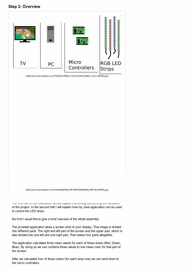
But first I would like to give a brief overview of the whole assembly.
The provided application takes a screen shot of your display. That image is divided
into different parts. The right and left part of the screen and the upper part, which is
also divided into one left and one right part. That makes four parts altogether.
The application calculates three mean values for each of these areas (Red, Green,
Blue). By doing so we can combine those values to one mean color for that part of
the screen.
After we calculated four of those colors (for each area one) we can send them to
the micro controllers.
(http://cdn.instructables.com/FV2/ACCZ/GKLJ1J3L/FV2ACCZGKLJ1J3L.LARGE.jpg)
(http://cdn.instructables.com/F52/9S88/GKLIWF7M/F529S88GKLIWF7M.LARGE.jpg)
The computer and the micro controllers are connected via serial connection.
After the micro controllers (in my case two Arduinos) received their messages they
can change the color of the LED strips. Therefor they change the PWM value of
their output pins. Each of these pins is connected to a transistor that switches the
externally powered 12V LED strips on and off.
Step 3: LED strips
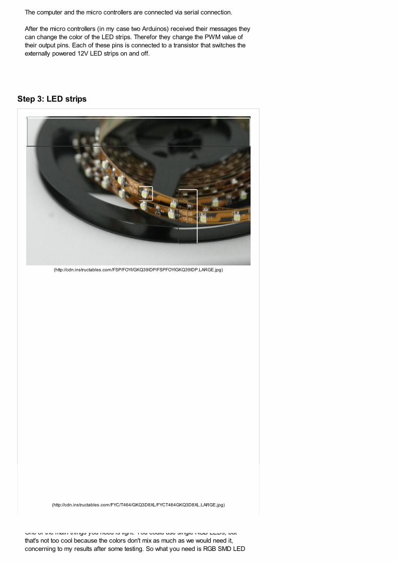
One of the main things you need is light. You could use single RGB LEDs, but
that's not too cool because the colors don't mix as much as we would need it,
concerning to my results after some testing. So what you need is RGB SMD LED
(http://cdn.instructables.com/FSP/FOYI/GKQ39IDP/FSPFOYIGKQ39IDP.LARGE.jpg)
(http://cdn.instructables.com/FYC/T464/GKQ3D8XL/FYCT464GKQ3D8XL.LARGE.jpg)
strips (abbreviations LOL).
These strips contain many RGB LEDs that mix color just like we want it. You can
cut them into pieces, another useful feature we need.
I bought a 5m (16 feet) strip on eBay for 32€ (44$) shipping included. That
package also contained a remote and a receiver so you can use the rest as
ambient light or do as I did. I sold the rest for 20€.
So what I got was 2m (6.5 feet, about 80 inches) of LED strip for 10€ (14$). And
that's okay, I guess. I cut it into four peaces. One for the left side, one for the
upper left, one for the right and one for the upper right part of my TV.
There are different kinds of strips. Some have got 60 LEDs/m and some only 30. I
bought one with only 30 LEDs/m which means 15 LEDs/part and that's enough for
this project.
These strips need an extra power supply because the micro controller must not be
used. So have (or buy) a power supply (12V) serving at least 1A (better measure,
because there are some really hungry LED strips out there). Mine is energy saving
(<0.7A on full white light for the length of 80 inches (2m)).
Step 4: Micro controller
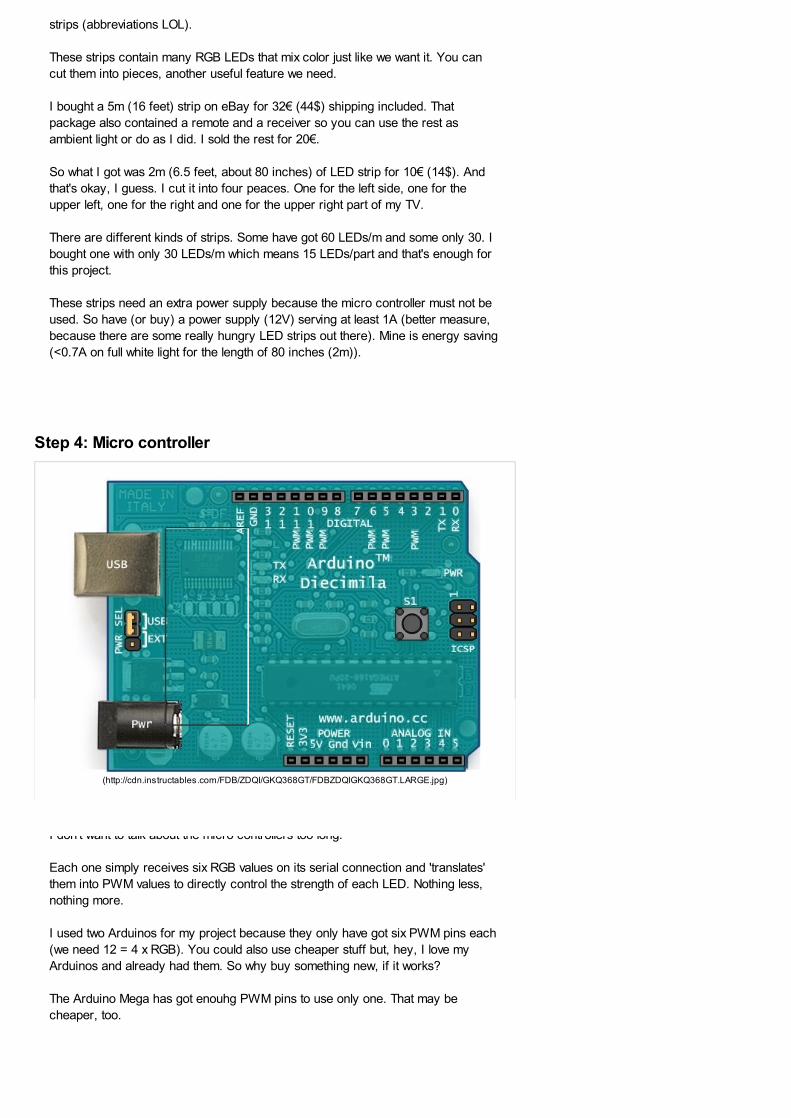
I don't want to talk about the micro controllers too long.
Each one simply receives six RGB values on its serial connection and 'translates'
them into PWM values to directly control the strength of each LED. Nothing less,
nothing more.
I used two Arduinos for my project because they only have got six PWM pins each
(we need 12 = 4 x RGB). You could also use cheaper stuff but, hey, I love my
Arduinos and already had them. So why buy something new, if it works?
The Arduino Mega has got enouhg PWM pins to use only one. That may be
cheaper, too.
(http://cdn.instructables.com/FDB/ZDQI/GKQ368GT/FDBZDQIGKQ368GT.LARGE.jpg)
Step 5: Hardware
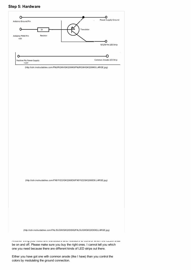
Another thing you need are transistors and resistors to control when the LEDs shall
be on and off. Please make sure you buy the right ones. I cannot tell you which
one you need because there are different kinds of LED strips out there.
Either you have got one with common anode (like I have) than you control the
colors by modulating the ground connection.
(http://cdn.instructables.com/FMJ/RGXH/GKQ39IK8/FMJRGXHGKQ39IK8.LARGE.jpg)
(http://cdn.instructables.com/FX6/YV22/GKQ368D8/FX6YV22GKQ368D8.LARGE.jpg)
(http://cdn.instructables.com/FAL/SUGW/GKQ3D8XQ/FALSUGWGKQ3D8XQ.LARGE.jpg)
Or your LED strip has got a common cathode. Than it's the opposite. Your LEDs
share their ground and what you control is the positive (+12V) power supply.
In the figure I attached to this step you can see how the pins have to be connected
when using a common anode LED strip. You need to solder this 12 times (for each
value = 4 x RGB).
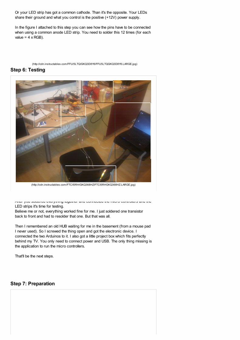
Step 6: Testing
After you soldered everything together and connected the micro controllers and the
LED strips it's time for testing.
Believe me or not, everything worked fine for me. I just soldered one transistor
back to front and had to resolder that one. But that was all.
Then I remembered an old HUB waiting for me in the basement (from a mouse pad
I never used). So I screwed the thing open and got the electronic device. I
connected the two Arduinos to it. I also got a little project box which fits perfectly
behind my TV. You only need to connect power and USB. The only thing missing is
the application to run the micro controllers.
That'll be the next steps.
Step 7: Preparation
(http://cdn.instructables.com/FFU/5LTQ/GKQ3D8Y6/FFU5LTQGKQ3D8Y6.LARGE.jpg)
(http://cdn.instructables.com/FTC/I5RH/GKQ368HZ/FTCI5RHGKQ368HZ.LARGE.jpg)
Because my source code is fully documented and easily to understand by looking
at the code I will explain what the application can do instead of explaining my
source code in deep. If you want to, you can just look up the code next to the
runnable jar file.
Nevertheless I will give a short overview of how the calculations work.
But first of all let's get my application to work.
INSTALL JAVA
The first thing you have to do if you want my program to run on your PC is to make
sure you have got a Java Runtime Environment installed on your computer. If you
do not have one installed yet, you can download it right here:
http://www.java.com/ (http://www.java.com/)
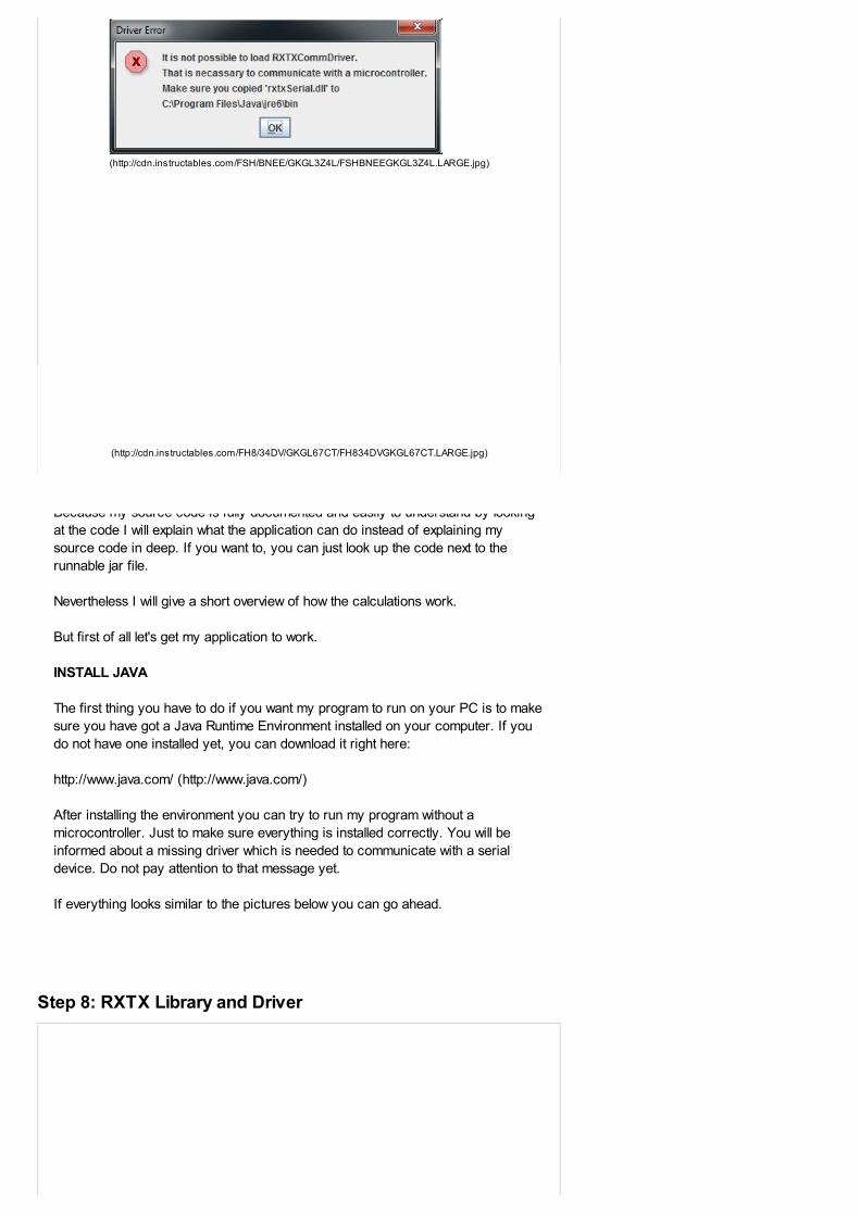
After installing the environment you can try to run my program without a
microcontroller. Just to make sure everything is installed correctly. You will be
informed about a missing driver which is needed to communicate with a serial
device. Do not pay attention to that message yet.
If everything looks similar to the pictures below you can go ahead.
Step 8: RXTX Library and Driver
(http://cdn.instructables.com/FSH/BNEE/GKGL3Z4L/FSHBNEEGKGL3Z4L.LARGE.jpg)
(http://cdn.instructables.com/FH8/34DV/GKGL67CT/FH834DVGKGL67CT.LARGE.jpg)
My Java application uses the RXTXcomm library to communicate with the
microcontrollers. That library allows an easy setup of serial connections to many
devices including the Arduino. Because a special serial driver is needed to access
a COM Port under Java you have to make sure that RXTX is installed correctly.
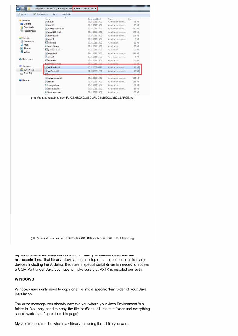
WINDOWS
Windows users only need to copy one file into a specific 'bin' folder of your Java
installation.
The error message you already saw told you where your Java Environment 'bin'
folder is. You only need to copy the file 'rxtxSerial.dll' into that folder and everything
should work (see figure 1 on this page).
My zip file contains the whole rxtx library including the dll file you want:
(http://cdn.instructables.com/FLI/CEM6/GKGL8BCL/FLICEM6GKGL8BCL.LARGE.jpg)
(http://cdn.instructables.com/FQN/OGRR/GKLJ1IBJ/FQNOGRRGKLJ1IBJ.LARGE.jpg)
TVBarLight\rxtx-2.1-7-bins-r2\Windows\i368-mingw32\rxtxSerial.dll
Copy that file into your 'bin' folder. That could be something like C:\Program
Files\Java\jre6\bin
LINUX
I've also tested my setup under Linux (Ubuntu 10.04) and it works. To use RXTX
with Linux you need to copy the file 'librxtxSerial.so' (you can find it in the rxtx folder
next to my jar) to another specific folder in your java path. For me, that folder is
/usr/lib/jvm/java-6-sun-1.6.0.24/jre/lib/i386
You should have a comparable folder on your system.
I really must say that my program slows down my Ubuntu. I cannot even watch a
movie while using my program and one cycle takes up to a quarter of a second.
That means the update rate is too slow. Windows works much better for this. I don't
know why. It's not the calculations.
MAC
Sorry guys, you have to find out by yourself, because I don't know anything about
Java and Mac OS (X).
FURTHER INFORMATION
If you still do not understand what I'm trying to tell you or just want to make sure
you really understood what I said have a look at this page:
http://www.jcontrol.org/download/readme_rxtx_en.html
(http://www.jcontrol.org/download/readme_rxtx_en.html)
If you want to know more about the libraries and how to use them this Wiki may
help you:
http://rxtx.qbang.org/wiki/index.php/Main_Page
(http://rxtx.qbang.org/wiki/index.php/Main_Page)
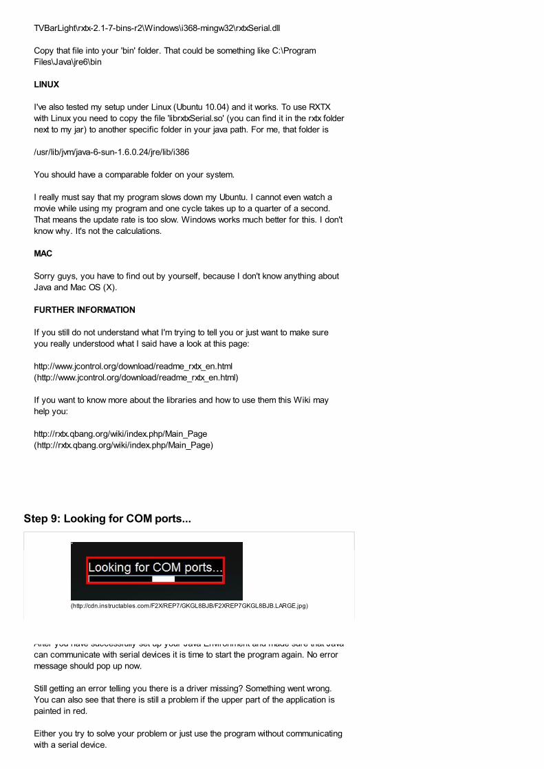
Step 9: Looking for COM ports...
After you have successfully set up your Java Environment and made sure that Java
can communicate with serial devices it is time to start the program again. No error
message should pop up now.
Still getting an error telling you there is a driver missing? Something went wrong.
You can also see that there is still a problem if the upper part of the application is
painted in red.
Either you try to solve your problem or just use the program without communicating
with a serial device.
(http://cdn.instructables.com/F2X/REP7/GKGL8BJB/F2XREP7GKGL8BJB.LARGE.jpg)
Let's say you solved all problems and no error message pops up. It now takes some
time to look for available COM-Ports (up to 30 seconds).
The waiting screen automatically closes when all COM ports are found. The main
application starts.
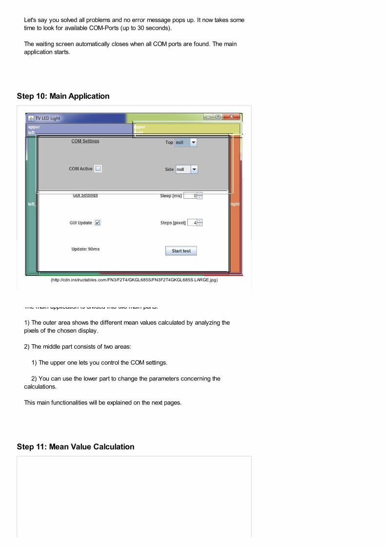
Step 10: Main Application
The main application is divided into two main parts:
1) The outer area shows the different mean values calculated by analyzing the
pixels of the chosen display.
2) The middle part consists of two areas:
1) The upper one lets you control the COM settings.
2) You can use the lower part to change the parameters concerning the
calculations.
This main functionalities will be explained on the next pages.
Step 11: Mean Value Calculation
(http://cdn.instructables.com/FN3/F2T4/GKGL685S/FN3F2T4GKGL685S.LARGE.jpg)
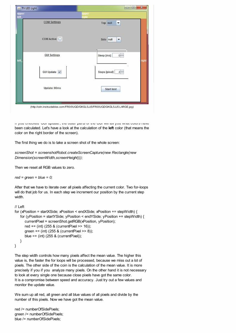
If you checked 'GUI update', the outer parts of the GUI will tell you what colors have
been calculated. Let's have a look at the calculation of the left color (that means the
color on the right border of the screen).
The first thing we do is to take a screen shot of the whole screen:
screenShot = screenshotRobot.createScreenCapture(new Rectangle(new
Dimension(screenWidth,screenHeight)));
Then we reset all RGB values to zero.
red = green = blue = 0;
After that we have to iterate over all pixels affecting the current color. Two for-loops
will do that job for us. In each step we increment our position by the current step
width.
// Left
for (xPosition = startXSide; xPosition < endXSide; xPosition += stepWidth) {
for (yPosition = startYSide; yPosition < endYSide; yPosition += stepWidth) {
currentPixel = screenShot.getRGB(xPosition, yPosition);
red += (int) (255 & (currentPixel >> 16));
green += (int) (255 & (currentPixel >> 8));
blue =+ (int) (255 & (currentPixel));
}
}
The step width controls how many pixels affect the mean value. The higher this
value is, the faster the for loops will be processed, because we miss out a lot of
pixels. The other side of the coin is the calculation of the mean value. It is more
precisely if you if you analyze many pixels. On the other hand it is not necessary
to look at every single one because close pixels have got the same color.
It is a compromise between speed and accuracy. Just try out a few values and
monitor the update value.
We sum up all red, all green and all blue values of all pixels and divide by the
number of this pixels. Now we have got the mean value.
red /= numberOfSidePixels;
green /= numberOfSidePixels;
blue /= numberOfSidePixels;
(http://cdn.instructables.com/FR0/0UQD/GKGL5JJ5/FR00UQDGKGL5JJ5.LARGE.jpg)
If you want the application to sleep for a while after one calculation cycle you can
change the value for 'Sleep'.
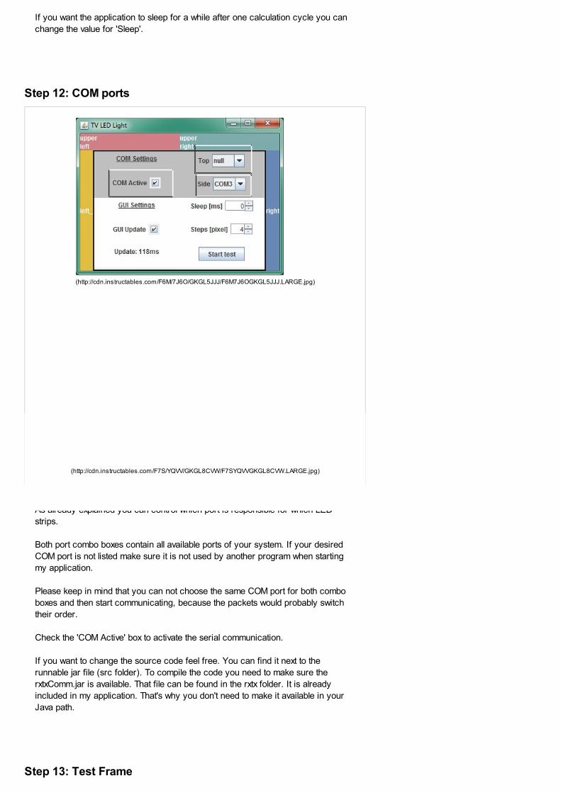
Step 12: COM ports
As already explained you can control which port is responsible for which LED
strips.
Both port combo boxes contain all available ports of your system. If your desired
COM port is not listed make sure it is not used by another program when starting
my application.
Please keep in mind that you can not choose the same COM port for both combo
boxes and then start communicating, because the packets would probably switch
their order.
Check the 'COM Active' box to activate the serial communication.
If you want to change the source code feel free. You can find it next to the
runnable jar file (src folder). To compile the code you need to make sure the
rxtxComm.jar is available. That file can be found in the rxtx folder. It is already
included in my application. That's why you don't need to make it available in your
Java path.
Step 13: Test Frame
(http://cdn.instructables.com/F6M/7J6O/GKGL5JJJ/F6M7J6OGKGL5JJJ.LARGE.jpg)
(http://cdn.instructables.com/F7S/YQVV/GKGL8CVW/F7SYQVVGKGL8CVW.LARGE.jpg)
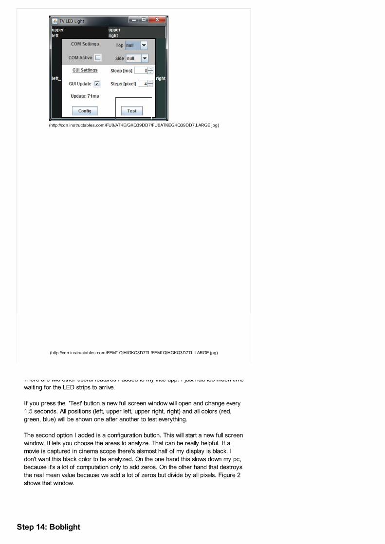
There are two other useful features I added to my little app. I just had too much time
waiting for the LED strips to arrive.
If you press the 'Test' button a new full screen window will open and change every
1.5 seconds. All positions (left, upper left, upper right, right) and all colors (red,
green, blue) will be shown one after another to test everything.
The second option I added is a configuration button. This will start a new full screen
window. It lets you choose the areas to analyze. That can be really helpful. If a
movie is captured in cinema scope there's alsmost half of my display is black. I
don't want this black color to be analyzed. On the one hand this slows down my pc,
because it's a lot of computation only to add zeros. On the other hand that destroys
the real mean value because we add a lot of zeros but divide by all pixels. Figure 2
shows that window.
Step 14: Boblight
(http://cdn.instructables.com/FU0/ATKE/GKQ39DD7/FU0ATKEGKQ39DD7.LARGE.jpg)
(http://cdn.instructables.com/FEM/1QIH/GKQ3D7TL/FEM1QIHGKQ3D7TL.LARGE.jpg)

EDIT:
My program just works fine for Windows Users. For my computer it takes about 20
Screenhots per second which is more than enough. I can even make it faster by
incrementing the step width to 10 or something.
But then I switched back to Ubuntu and wanted to watch a movie with my Dolby
Digital Sound System and my new LED Lights. There was a problem. Linux does
not allow fast screenshot taking as Windows does. It was about 4 screenshots per
second and the movie stopped while processing. That was not acceptable so I
found another useful program, which is written in C++ and does just as much as
my application does (acutally it makes a loooooooot more, if you want). But without
the nice user interface. It's called Boblight and Linux users can compile the source
code on their own.
Make sure you have all required libs:
sudo apt-get install libx11-dev libgl1-mesa-dev libxrender-dev portaudio19-dev
libavcodec-dev libavformat-dev libswscale-dev libavdevice-dev
Here you can find the source code of Boblight.
http://code.google.com/p/boblight/source/checkout
(http://code.google.com/p/boblight/source/checkout)
After you installed the program you need to create a file called boblight.conf. That
file tells boblight daemon where to find the micro controller and what 'protocol' to
use.
I just added my boblight.conf-file to this step, so you can download it and change it
to your desires. You have to change the devices output to your serial ports.
In my example file one device is set up for Ubuntu and one for Windows. That is
just an example and does not work, because you need to have both Linux or both
Windows. I just wanted to show how to name the ports. So either change it to
"comXX" (Windows) or /dev/usbXX for Linux.
After everything is installed you can start the boblightd (daemon) which waits for
clients to connect and then sends data to the micro controllers.
That client may be boblight-X11 which takes screenshots of the screen and
analyzes them just like my application did.
Windows users can also use boblight (not the current version, but an old one).
You only need to download this folder and copy the boblight.conf file into
http://www.xs4all.nl/~loosen/boblight/boblight-1.3-beta1.rar
(http://www.xs4all.nl/%7Eloosen/boblight/boblight-1.3-beta1.rar)
After you changed the the configuration file to your needs start the daemon and
then start getpixel.
Windows Vista and W7 Users have to change their theme to Windows 7 Classic,
because the getpixel()-function does not work with aero-themes.
For me it just works fine on Windows 7 and Ubuntu and does not require that much
computation power.
If you want to find out more about boblight and how to use it (especially about the
config-files) checkout
http://blogger.xs4all.nl/loosen/ (http://blogger.xs4all.nl/loosen/)
(old)
or http://code.google.com/p/boblight/ (http://code.google.com/p/boblight/) (current
project location).
We have a be nice comment policy.
Please be positive and constructive. I Made it! Add Images Post
(/member/Eclipse+TV+Lights/)
9 months ago Reply (CVJMHH6HLSH803K)
flag
(/member/rajshrimohanks/)
1 year ago Reply (C5ZXTRAH6MF3WXX)
flag
(/member/GeneRalf/)
2 years ago Reply (CLL0AYBGSVJVTJ5)
flag
(/member/ledtvlight/)
2 years ago Reply (CYKI5DZGSVJVUTS)
boblight.conf (/files/orig/F43/ETY7/GKS0RSQS/F43ETY7GKS0RSQS.tmp)877 bytes
1-40of 67
Next » (http://www.instructables.com/id/Java-Microcontroller-LED-TV-Ambient-Light/?&sort=ACTIVE&limit=40&offset=40#DISCUSS)
Eclipse TV Lights (/member/Eclipse+TV+Lights/)
Simply amazing job on this ambient LED
setup. I can tell a lot of thought and time wentinto figuring this all out. How long is
everyone spending to put these LED kits
together using your instructable?
rajshrimohanks (/member/rajshrimohanks/)
Can C/C++ be used to program the software part..? Is there any way using it?
GeneRalf (/member/GeneRalf/)
Please help,
I am desperate with my MEGA2560 and the SW for this project.
There is a package in all of the java-files "package de.zucizu.ledlights" which can not
be found by the compiler. So I deleted this in every file and the compiler is actuallydoing his job.
Everything seems to work however the LED / PWM is not working at all with the
provided Arduino-SW.
If I am using a port-sniffer I can see, the RGB values sent by the Java app to thearduino, I do also see the flickering of the Rx LED... but the brightness is not
changing.
Using a terminal programm and send it manully it is working fine at least for LEDpin
13 (not testest the other outputs yet)
Is this because of the missing package "package de.zucizu.ledlights" ?
Or is there anything else what I miss here ?
Thanks for your help
ledtvlight (/member/ledtvlight/) (author) GeneRalf
Hi.Actually I've build another one for
somebody and I used an Arduino
Mega, too. I had to change some
code because I haven't tried it
before and couldn't confirm if itworks or not. But now everything
works fine. I've packed everything
into a jar file to use it immediately
flag
(/member/GeneRalf/)
2 years ago Reply (CLNWQ4WGSWZBPPM)
flag
out of the box. But you can also
see the source code, because I
added them to the package. The
Arduino source code is differentnow. But just have a look.
http://uploaded.to/file/9h8d5n1s
The order of bytes sent to the μCis the following:
First 0xFF to synchronize and then
left RGB and then upper left RGB.
After that 0xFE another
synchronisation, Upper right RGB,
right RGB.
And Arduino Pins: Left RGB = 2,3,4
Upper Left = 5,6,7
Upper Right = 8,9,10
Right = 11, 12, 13
Of course you can change it just
how you need it in the source
code. Hope I could help you.
Just ask if there are any problemsleft.
GeneRalf (/member/GeneRalf/) ledtvlight
Even with the SW for the
MEGA2560 I am experiencing the
same problem that the LED/PWM is
not switching according to the
transmitted data from the JAVA appwhile sending the data via a terminal
program it works fine.
I am wondering, how the
synchronization is working anyway ?
Let say the PC is
sendingcontinously some data ...
00 00 FF 00 00 00 FE 00 00 00 00
...You don't know the exact timing
when the uC starts reading the data.
If the uC missed the e.g. FF for the
left - lefttop side, the next FE which
was actually meant as a color valueis miinterpreted as start value for
right - top right.
So to avoid this we need to adjust
the max value in the JAVA app ofthe sent data to 253 instead of 254
and 255.
And even the JAVA is not sending
FE and FF as color value anymore,we still do not know when the
inputBuffer of the uC is loaded with
just color values
(/member/ledtvlight/)
2 years ago Reply (CTRBHPWGSWZ9WNS)
flag
(/member/GeneRalf/)
2 years ago Reply (C4J4IWWGSUSMUDE)
ledtvlight (/member/ledtvlight/) (author) GeneRalf
Mine really works fine.
You wrote:
>Let say the PC is
sendingcontinously some data
...
> 00 00 FF 00 00 00 FE 00 0000 00 ...
> You don't know the exact
timing when the uC starts
reading the data.
> If the uC missed the e.g. FFfor the left - lefttop side, the next
FE which was > >actually
meant as a color value is
miinterpreted as start value for
right - top right.
It won't be misinterpreted.
remember the boolean called
'left'. If the uC misses the FF it
would jump into the if-queryasking for left, because left is
true. then it would read a byte
and see that the byte is not FF.
nothing would happen. That
would continue as long as notFF is being sent.
GeneRalf (/member/GeneRalf/) ledtvlight
I am still haveing issues but I am ableto narrow it down.
So everything is working fine with the
following method
(I am using eclipse for the JAVA)
0. Put a breakpoint in the JAVA
before the RGB data are written to
the Outputstream
1. start the app with the debugger 2. select in the JAVA app the COM
port and activate the port
>> Now here I am experiencing that
LED13 goes ON and remains ONeven
no data is sent ?
3. Wait a couple seconds (e.g. 10s)
and let the debugger run for another turn
>> All LEDs are ON respectively on
the level what was sent
I am using a Arduino Mega2560 and
progrmam it with the IDE from
www.arduino.cc and program the uC
via USB.
So there is a bootloader on it..is thebootloader turning on the LED13 ?
Does this might cause the problem?
Even the Java is sending for 10sec.
the uC is not doing what expect. with
the break I have mentioned here it isworking fine ..
flag
(/member/ledtvlight/)
2 years ago Reply (C8S180ZGSYEQCHN)
Any idea ?
ledtvlight (/member/ledtvlight/) (author) GeneRalf
Hey!
Always plugin the uC, wait at
least 10 seconds and _THEN_
start the java program. I guess
you know that, but maybesomeone else could need that
info. Also make sure no other
program wants to send anything
over your COM. close the
Arduino IDE, although it shouldn'tmake any problems, but who
knows.
You wrote:
>> Now here I am experiencing
that LED13 goes ON and
remains ON even
no data is sent ?
That is not correct and does not
happen in my setup. maybe you
chose the wrong board in your
Arduino IDE? for example
arduino mega 1280 instead of2560 or something. if that is not
the problem, try to restart your uC
manually by pushing the reset
button on your board at that time.
but i guess that wouldn't helpeither.
LED 13 is connected to a strip of
LEDs, too isn't it? So one color
of one strip has to blinkrandomly, too. It has to be the
blue color of the right strip, if you
connected everything the way I
wrote it in one comment,
otherwise it has to be anothercolor. but pin 13 has to be
connected with a strip, because
only pins 2 to 13 are PWM pins
and that's exactly 12, just as we
need it. Am i correct?
I guess you connected everything
correctly because you say, it is
working with your method
explained. At least for one cycle.
Probably it is an issue caused by
the operating system handling
the COM ports. Windows 7 for
example always checks thewhole bunch of Com ports which
takes up to 5 seconds everytime
you try to change something with
your serial. you should note that
when you use the Arduion IDEand try to change the comport or
the board.
data is being sent over the serial
connection to checkout if that
flag
(/member/GeneRalf/)
2 years ago Reply (CYZ9OKDGSUSNDB8)
flag
(/member/Soulforger/)
2 years ago Reply (C8ZENYUGTCP481H)
port is available (or something
like that). That lets the
microcontroller restart and blinkrandomly, which is no problem
but should be mentioned. That
could happen when the 'Looking
for Com Ports' waiting screen
appears or when you plugin youruC for the first time. Just wait a
few seconds before activating
the COM port in my program until
the uC is setup correctly and
waiting for data.
If all that won't help i have got
another idea. we have to check
out if it is a problem on your pc or
on your uC. we could try it withboblight. for that we have to
change the source code. we
have to break down the problem
to solve it. but we will solve it, I'm
sure :-)
Check your hardware (pins 2-
13), check your board settings in
arduino IDE!
GeneRalf (/member/GeneRalf/) ledtvlight
I am almost 100% positiv that LED is.Set by the bootlloader, not from you
java app. When activating the com
port in thd java,led13 turns on. So the
uc is receiving the rgb data and is
doing nothing with it since the crc isprob,@ably always wrong. Thats way
it is working perfect once i stop the
java with a breakpoint and let it run
after 10s have ellapsed. It would help
jf you could add a start sequence sentby the uC eg 0xAA 0x55 to the java.
Once this sequence was received the
uc us ready to go otherwise still he us
still busy in the bootlader. It is
independent of win7 becauze samebehavior with xp.
Thx
Soulforger (/member/Soulforger/) GeneRalf
Hi,
First of, thank you very much for a verynice instructable!
Unfortunately I too have the same
problem that only blue light is showing
from the pin 13 and that's it. Nothingelse is happening even though I see
that the Java app is sending data to
the Mega.
Did you guys figure this out or is it stilla work in progress?
flag
(/member/GeneRalf/)
2 years ago Reply (CZ66WCAGTKH9QNO)
flag
(/member/aborsciov/)
2 years ago Reply (CBZGR8CGV1HFILH)
flag
(/member/GeneRalf/)
2 years ago Reply (C8T4AN1GV0KKFT1)
flag
Thanks for your time and I too hope
that this problem can be solved!
GeneRalf (/member/GeneRalf/) Soulforger
Try my Python program. My ArduinoMega2560 runs perfectly fine with it
now http://db.tt/vguZrVVH
Everybody else who want to checkout this program let me know how to
improve it. This is actually my veryfirst Python program ;-)
aborsciov (/member/aborsciov/) GeneRalf
Thank you for the Python program. Atthe moment I tested it just on
breadboard with the multimeter andthe pwm pins vary the voltage.I had the same problem with pin 13
and it seems to be because of theserial communication but I don't know
how to solve it.
boblight does not work for me at all.
I hope that after I get all my parts
everything will work fine with thispython program.Great job!
I struggled a bit though to find and
install all libraries that were necessary.
Is there a posibility to compile it to an
executable? so I don't have to open itin python all the time.
GeneRalf (/member/GeneRalf/) aborsciov
Once the libraries and Python are
installed you can have a shortcut onyour Desktop and doubleclick thePython script and it starts
automatically. Or you can start it from the comand line
python yourscript.py
But I will post you an exe-file soon.
Regarding the functionality of boblight
and ledtvlights original JAVA program,I am pretty sure it is because of thedifferent Serial-Port-conections on the
different Arduino boards. Some are having the FT232 chip,
some of them are having a ATMega8with bootloader which needs an extrasecond before respectively is making
an Auto SW Reset .. look here forsome details
http://arduino.cc/en/Main/ArduinoBoardMega2560
(/member/aborsciov/)
2 years ago Reply (CN58BYNGV35847E)
flag
(/member/ledtvlight/)
2 years ago Reply (COHHBK4GUGDANII)
flag
(/member/ledtvlight/)
2 years ago Reply (CQDVU58GSUSPOCL)
flag
aborsciov (/member/aborsciov/) GeneRalf
I know about the different chips, I havemega2560 which has ATMega8 andyes it causes problems.
I read many posts about this and foundout that there is actually a new
firmware supposed to correct this. Iflashed it on my arduino using the FLIPutility from Atmel, but I'm not completely
sure it changed sth. I mean the logshowed that the update was successful
but I'm not sure if it changed sth, thebootloader version that I have now is1.2.0 and I don't know which is the
original one.It is tricky to reset the board and put it
in DFU mode for the flash update but Imanaged to collect several pieces ofinformation from different forums.
I tried again the JAVA application with
no success. Your application worksnow just if I change the delay value in itto 0 vs 4 the default that you put.
I still need to receive the uln2003a ICs
and then I will be able to fully test it withLEDs.Your app is fine now, I managed to
launch it directly so it's all right.
With boblight the problem comesbecause I don't quite understand howto change the config file for my needs,
thus it gives me an error on launch thatit cannot access the com port, although
in the config file I modified it.
I can't wait to finish the whole thing,
maybe then we can give the creator ofthis topic some info about some
tweaks that need to be made in orderfor it to work.I would like to have the JAVA app
running as well or at least boblight butthe only solution I find is to order a
mega1280.
ledtvlight (/member/ledtvlight/) (author) GeneRalf
Hi, thanks but I don't have theMega anymore. But as soon as I
have build my own again I willrewrite the code to use it with mysetup and will post the results.
ledtvlight (/member/ledtvlight/) (author) Soulforger
Hey, I do not have a working
arduino here at the time,because I sold the ambient lights
I built. Until I get my tlc5940 icannot test it, sorry! But as soonas I get them I will work on that
problem.
(/member/GeneRalf/)
2 years ago Reply (CLEKRK5GUEK9SD4)
flag
(/member/ledtvlight/)
2 years ago Reply (CYKANT6GUGDANI3)
flag
(/member/n3v/)
2 years ago Reply (CFC2GV9GTE4JYCT)
flag
(/member/ledtvlight/)
2 years ago Reply (CH4TIXSGUGDANIE)
flag
(/member/Wes1180/)
2 years ago Reply (COZP2ZNGS3BF3Z2)
flag
GeneRalf (/member/GeneRalf/) ledtvlight
" ... The Mega2560 differs from allpreceding boards in that it does not
use the FTDI USB-to-serial driverchip. Instead, it features the
Atmega8U2 programmed as a USB-to-serial converter ..."
could this be the root cause incombination of the Auto-Reset when
the controlling PC opens the com port?After Reset (Com port opening) it
takes about 1s before the Arduino isready to receive and control the PWM
...
ledtvlight (/member/ledtvlight/) (author) GeneRalf
May be. I don't know and actually Ido not have the time to test theMega anymore. I built the whole
thing for a person with an ArduinoMega and didn't have any
problems at all. Now I don't havethe Mega anymore.
I will update the whole tutorial in afew days to two weeks which will
make it much easier. By the waythis is much easier and gives youreally good results:
http://ladyada.net/make/adalight/
n3v (/member/n3v/)
Really nice project, I came across it when looking into the Software side, since I cam
up with an own HW design, using a TLC5940. Its been working really nice under Linuxwith boblight. However, under Windows it seems that the config file does not allowhaving two bytes for synchronising (works perfectly fine in ubuntu) and because of this
i keep getting flashing colors, as the FF value is sent as a color directly to the LEDs. I was wondering if anyone else has had such problems, or if it has something to do
with windows7 dropping serial data. I'm using a FTDI FT232RL for the usb to serial.
ledtvlight (/member/ledtvlight/) (author) n3v
Just change the 'protocol' to onlyhave one sync-byte.
Wes1180 (/member/Wes1180/)
This looks like a really cool project, I am considering doing it and so I have a couple
of questions.
How long should the strips be for a 22" screen?
I have never done anything like this before so what sites should I look at to get similar
prices to what you did?
ledtvlight (/member/ledtvlight/) (author) Wes1180
(/member/ledtvlight/)
2 years ago Reply (CMNSRDMGSIP0ZB8)
flag
(/member/Wes1180/)
2 years ago Reply (CH9MAV3GSNQR8JR)
flag
(/member/ledtvlight/)
2 years ago Reply (CFON2MDGSUT1N8U)
A 22" screen means the diagonal is 22" long which means the width of
your screen is 19.2" and the height is 10.8" (Pythagoras, lol).
You need (2*10.8")+19.2" of strip. So about 40" which is 1m. Here you
could buy it online in China without shipping costs. I guess it takes about1-2 weeks to arrive and I have never had any trouble with this store.
http://www.dealextreme.com/p/waterproof-1-meter-4-5w-30-led-rgb-light-strip-dc-12v-16868
You could also buy it on eBay for about the same price I guess.
The other parts:
TLC5940 and ULN2003 - Electronic store nearby or eBay.Arduino - Ebay (Fake from china works good as well) or Sparkfun (if you
want it original, but more expensive).
Wes1180 (/member/Wes1180/) ledtvlight
So I had a search and came acrossthese.
http://bit.ly/nQLrz4 (arduino mega)
http://bit.ly/nhN9HI (ULN2003)
http://bit.ly/n8KYSy (LEDs)
A person in the comments of the LED
page mention 3 parts where you cancut off, is that going to be a problemsaying this requires 4 parts, should I
consider getting a different one?
Also what type of power supply am Igetting, I know 12v with at least 1ampbut would it be one of these?
http://bit.ly/nEdEr1
And I'd just like to say that I reallyappreciate your help, especially since
I am new to all of this and may beasking some silly questions :)
ledtvlight (/member/ledtvlight/) (author) Wes1180
The Arduino price is okay.
You would need more LEDs, I
guess. So buy at least two of the1m strips. For my 37" TV 2meters of LED strips was
perfect. And for a 46" tv it wasstill really good. So if you have a
TV of this size or even biggeryou would definitely need longerstrips. You looked for waterproof
strips which is absolutely notnecassary. Look at this article:
http://goo.gl/EeoFc
It costs a little bit more but youget 5 Meters and could sell the
rest on the internet and get atleast 20$ for the rest so it's still
flag
(/member/Wes1180/)
2 years ago Reply (CIEOQOLGT2P39Q5)
flag
(/member/ledtvlight/)
2 years ago Reply (CKNU7TUGSUSPOCZ)
cheaper. And these LEDs canbe used for all kind of stuff.
Maybe you want to build anotherone for a friend or something.
These LED strips can be cutevery 3 LEDs, so every 10cm.
But then you have to solder yourown connections which may be
a bit tricky. But every 50cm thereare solder points on the stripswhere you just have to solder a
cable to the strip and that isreally easy.
Your power supply link doesn'twork.
I would prefer a bigger powersupply than 1A because you can
use these power supplies for allkinds of projects and maybe youwant to use it with the rest of
your LED strip which is 3 metersof length and need more power.
Also you have got somereserves and the supply doesn'tget that hot.
I guess you come from Great
Britain, because one of yourlinks leaded me to a britishhomepage. but you can get
these power supplieseverywhere:
http://goo.gl/MUBqu
Wes1180 (/member/Wes1180/) ledtvlight
First I'd like to say thanks for beingpatient with me.
I am considering getting a 3 screen
setup, so would you suggest using 6strips, 2 on the top of each screen andnon on the sides becuase of the
positioning. (this would be half a meteron the top of each screen as they are
only 22")
Can the arduino mega support 6
strips?And can your program support 3
screens?
The resolution would be 5760 x 1080
ledtvlight (/member/ledtvlight/) (author) Wes1180
No my java program lets youonly choose one single monitorbut you can change that, so you
can use your three screens. theonly problem is the power of
your cpu because thecalculations will be calculated inone single thread and not on
your GPU. i could change that ifyou want. Then I guess it would
flag
(/member/Wes1180/)
2 years ago Reply (CG00JU1GSUSPOHD)
flag
(/member/ledtvlight/)
2 years ago Reply (CUMFLU6GSUSPOPH)
flag
(/member/Wes1180/)
2 years ago Reply (CENNMC2GTCP49JH)
flag
(/member/LassiVV/)
2 years ago Reply (COFV32NGT8EUQYN)
flag
(/member/ledtvlight/)
2 years ago Reply (CZAX2AKGSUSPOD7)
flag
get faster. maybe you woulddonate a few dollars for mywork, because it's a little bit
more investment :-/
Wes1180 (/member/Wes1180/) ledtvlight
I don't think i'm going to be getting thethree screens, but i would donate if I
could, but unfortunately I don't reallyhave enough money at the minute,one of the reasons why I haven't
gotten any of the stuff for this yet,sorry.
ledtvlight (/member/ledtvlight/) (author) Wes1180
Hi, no that shouldn't mean you
have to send me money. I justwanted to tell you that if I have to
make such big changes to thesource code and test everythingthat this costs a lot of time and it
would just be fair if i at least geta little something for it. I'm sorry
for your current financialsituation and hope you can getall the parts in a near future.
Wes1180 (/member/Wes1180/) ledtvlight
I was just wanting you to know that if I
could, I would donate as I like the stuffyou have done
LassiVV (/member/LassiVV/)
Hello, first of all awesome project thanks to you :) I make hardware ok, but no i dont
get boblight to work anyway. With you own java program all works ok, but i want useboblight because you recommend that.
I try change boblight config file. I can change all com port, channels pcs and othersettings ok. But no light light up my arduino board. And tx/rx leds no blinking when i
start boblighttd and after that getpixel progman. Both programs shows only black(black) Windows CMD -window.
Can you copy/paste or upload config file what works with your arduino code? Orexplain can i change arduino code/or boblight config file right.
I am very thankfull if you can answer to me with this problem :) I can c/p somepicture/video with my setup when i get that working, if that ok.
ledtvlight (/member/ledtvlight/) (author) LassiVV
I will do that as soon as I get mytlc5940 and can build anotherambilight. I will then update my
project as well because I think itis much easier and really cheap.
desol007 (/member/desol007/)

(/member/desol007/)
2 years ago Reply (CSHGTB1GQX1VN4U)
flag
(/member/ledtvlight/)
2 years ago Reply (C6DOWT1GSVJVV7M)
flag
(/member/desol007/)
2 years ago Reply (CKFIBQKGSVJVZ1C)
flag
(/member/estqwerty/)
3 years ago Reply (C0PXVPRGNRT22CT)
flag
(/member/ledtvlight/)
3 years ago Reply (CI5TS6BGNRT22EP)
flag
(/member/estqwerty/)
3 years ago Reply (C5KNY3JGNSNINH9)
flag
(/member/ledtvlight/)
2 years ago Reply (CKAOAHLGSVJVV7R)
flag
(/member/ledtvlight/)
2 years ago Reply (CN6LY12GP7II7GR)
flag
I am not sure how to install boblight. I have your software working but I can not getboblight to work. I have win7, arduino mega and uno. I am not sure how or where to
put the boblight.conf file at. Thanks for any help
ledtvlight (/member/ledtvlight/) (author) desol007
It's not necassary to 'install'boblight. It just works out of the
box. First start boblightd (thedaemon who listens) and afterthat start the getpixel-program
which analyzes your screen andsends the data to the daemon
who then sends the bytes to yourmicrocontroller.
desol007 (/member/desol007/) ledtvlight
Thanks, I was confused now I got it
estqwerty (/member/estqwerty/)
Great video, i'll build it only to watch star wars again !!!
i researched how to add more PWM ports to arduino.take a look at this : http://www.arduino.cc/playground/Learning/TLC5940
may will be able to use only one arduino ???
ledtvlight (/member/ledtvlight/) (author) estqwerty
Yes, it seems as if that is a goodhardware part. I guess you can
use it to drive more LEDs.
estqwerty (/member/estqwerty/) ledtvlight
can you update the code if this isworking?
will one arduino will be able to controlmore strips - i mean it is not a cpuissue?
ledtvlight (/member/ledtvlight/) (author) estqwerty
no it's not a cpu issue. just add a
few tlc5940 and you can controlmany strips. i just ordered two
tlc5940 from china. it takes sometime to arrive but then i will testthem out. maybe it's still
interesting for you.
ledtvlight (/member/ledtvlight/) (author) estqwerty
Yes it seems possible to me.
gacorda (/member/gacorda/)
(/member/gacorda/)
3 years ago Reply (CEBR9RZGMJT3Y55)
flag
We have a be nice comment policy.
Please be positive and constructive. I Made it! Add Images Post
You could use tlc5940 chip which can prevent the use or pucrchase of anotherarduino.
1-40of 67
Next » (http://www.instructables.com/id/Java-Microcontroller-LED-TV-Ambient-Light/?&sort=ACTIVE&limit=40&offset=40#DISCUSS)
About Us
Who We Are (/about/)
Advertise (/advertise/)
Contact (/about/contact.jsp)
Jobs (/community/Positions-available-at-Instructables/)
Help (/community?categoryGroup=Help)
Find Us
Facebook (http://www.facebook.com/instructables)
Youtube (http://www.youtube.com/user/instructablestv)
Twitter (http://www.twitter.com/instructables)
Pinterest (http://www.pinterest.com/instructables)
Google+ (https://plus.google.com/+instructables)
Tumblr (http://instructables.tumblr.com)
Resources
For Teachers (/teachers/)
Artists in Residence (/group/air/)
Gift Pro Account (/account/give?sourcea=footer)
Forums (/community/)
Answers (/tag/type-question/?sort=RECENT)
Sitemap (/sitemap/)
Go Pro Today » (/account/gopro?sourcea=footer)
We're Hiring! » (/community/Positions-available-at-Instructables/)
Mobile
Download our new apps for iOS,Android and Windows 8!
Android
(https://play.google.com/store/apps/details?
id=com.adsk.instructables)
iOS
(https://itunes.apple.com/app/instructables/id586765571)
Windows
(http://apps.microsoft.com/windows/en-
us/app/7afc8194-c771-441a-9590-
54250d6a8300)
Join our newsletter:
Terms of Service (http://usa.autodesk.com/adsk/servlet/item?siteID=123112&id=21959721) |
Privacy Statement (http://usa.autodesk.com/adsk/servlet/item?siteID=123112&id=21292079) |
Legal Notices & Trademarks (http://usa.autodesk.com/legal-notices-trademarks/) | Mobile Site (http://m.instructables.com)
(http://usa.autodesk.com/adsk/servlet/pc/index?id=20781545&siteID=123112)
Join!
© 2014 Autodesk, Inc.
Englishenter email