LED Perimeter EPR-1800 Ezer - US Ophthalmic1 DearUsers: Thank you very much for choosing EPR-1800...
44
0
Transcript of LED Perimeter EPR-1800 Ezer - US Ophthalmic1 DearUsers: Thank you very much for choosing EPR-1800...

0

1
Dear Users:Thank you very much for choosing EPR-1800 automatic computer perimeter
manufactured by us.
For your security and benefit, please read the <Operation Instruction> as well as
all the datum of the instrument carefully before using it.
If you do not operate the instrument according to the Operation Instruction, we shall
not take any responsibility.
About <Operation Instruction> of this InstrumentThe copyright of the operation instruction belongs to us;
The content of the operation instruction is written according to the physical goods;
If you can not understand some of the content or clause, or if you meet technical
problems when using it, please do not hesitate to contact us,
We have the right of interpreting and revising this operation instruction.
.

2
Content
1. Introduction………………………………………………3
2. Note………………………………………………………4
3. Technical service of Parameters …………………………5
4. Installation ………………………………………………7
5. Function of the Software…… …………………………19
6. Operation Steps ……………………………………… 23
7. Maintenance……………………………………………29
8. Interpretation …………………………………………31
9. Parameter Introduction…………………………………35
10. Declaration…………………………….…………………42

3
1. Introduction
1.1 Brief IntroductionThe system of EPR-1800 fully automatic perimeter is a new generation based on
the old generation. It has two examination resource colors, kinds test program and
strategy. It has the characteristics of full-function, high precision and speed.
Besides the above characteristics, the whole system also has the characteristic of
high dependability and steady performance.
1.2 Registering Information Name: EPR-1800 perimeter
1.3 Purpose of InstrumentThis instrument is used for examining the change of visual field which may be
hurt by glaucoma, visual disease, disease of brain surgery and disease of retina.

4
2. Notes2.1 Caution:The local voltage must measure up to the standard voltage required by us. If the
voltage is not steady, please install a steady- voltage instrument. We shall not take
any responsibility for the damage due to the unstable voltage.
2.2 Notes:To avoid being damaged by the environment (Damp, Dusty, Liquid, under the sunand so on), the instrument should be putted at the dry place.
Do not let the liquid or any other small objects run into the instrument, otherwisethese objects may make the inner parts of the instrument short-circuit, and evenmake the users get an electric shock or even cause a fire hazard.
2.3 Caution:Without the permission of us, do not open the box of the instrument,or we will nottake the consequences.
2.4 Notes:The instrument can only be installed in the dark room. And it can only be operated
by those who have been trained by engineers of us, or our authorized distributor.
It belongs to BF common instrument according to thedegree of protecting voltage
Dangerous Voltage
Notes!Look through the file
Earth wire

5
3. Technical Service of the Parameter
3.1 Transport and StoragePrevent the instrument from damp, being inverted and being shaken violently. Keep
it in the room in which the relative humidity is less than or equal to 85 percent, the
environment temperature is between :5℃ -40℃ , the scope of air pressure: 760
hPa~1060 hPa and well ventilated without corrosion gases.
If the instrument need moving or transporting in a short distance, you should take
apart all the connection wires and be transported by single. If the instrument must be
transported in a long distance, re-pack it into its packaging box and then transport it.
3.2 Performance of Perimeter Scanner3.2.1 Radius of stimul
3.2.2 ator: 30cm
3.2.3 Stimulating source of white LED. fixing spot is green.
3.2.4 Stimulating intensity :0 db-40 db
3.2.5 Intensity of background illumination: 31.5asb
3.2.6 Rear projection, and the diameter of light spot is Goldman III.
3.2.7 The number of stimulating and the stimulating time:
A.390 spots;
B: Stimulating retention time: 0.2s/Adaptive
C: Stimulating spacing interval: 0.2s/Adaptive
Window of eye-position tracking: White-black CCD, directly tracking the
testing eye;3.2.8 0°~90°scope can be tested in one time
3.2.9 The trip of chin rest: up-down: ≥60mm; right-left ≥30mm;
3.3 Working Environment of the Perimeter3.1 Environment temperature: 5degree –40degree
3.2 Relative humidity: ≤85%
3.3 Atmospheric pressure: 700hPa--1060hPa
3.4 Power: AV 100~240V ; Frequency: 50~60Hz
3.5 Input power: ≤400VA

6
3.4 Characteristics3.4.1 The instrument belongs to type I, BF Model common instrument
3.4.2 The instrument is supplied by single-phase net power
3.4.3 The form of the instrument is intermittent working form

7
4. Installation4.1 Hardware4.1.1 Picture of the Whole Instrument
4.1.2 Introduction of Hardware-Perimeter stimulus unit.
-Laptop computer with large capability memory and hard disk, CD-ROM driver,
USB ports and one combination-port.
- Laser-jet printer▲The Front Picture of the Stimulator
▲ The Back Picture of the Stimulator
StimulatorComputer
Printer
Forehead Rest
Chin Rest
Power On/Off
USB Port

8
▲Main Spare-Parts
Printer
Structure Flowchart
4.2 Installation Environment4.2.1 The instrument must be installed in the flat ground with no slope;
4.2.2 The instrument must be installed in the clean, quiet and dry room;
4.2.3 The instrument must be installed in the dark room where nothing can be
seen within one meter.
4.2.4 The instrument must be installed with special ground wire;
4.3 Hardware Setup4.3.1 Connect Perimeter and Computer with the new USB Serial Port Wires we
provide.
ResponderStick
Serial Port Wire
Stimulator Responder
Computer
Display Print
Power wire

9
4.3.2 Connect the Power of the Perimeter.
4.3.3 Take out the fixed foam inside the Perimeter. Fix the Responder into the connector.
4.4 Software Setup
4.4.1 Windows System Requirements
English/ Simplified Chinese Version Window XP 32 bit ProfessionalEnglish/ Simplified Chinese Version Windows 7 32bit/ 64bit ProfessionalEnglish/ Simplified Chinese Version Windows 7 32bit/ 64bit Ultimateor English/ Simplified Chinese Version Windows 8 32bit/64bit ProfessionalPS: Our perimeter software only support English/ Simplified Chinese Version
Windows system, if user running others language Windows system, there will beunreadable code showed during install procedure and on software, or otherunpredictable error will be occur. Please use relevant system we recommended.
Power on/off
Power supply USB connectingport

10
4.4.2 Hardware RequirementsBefore you install PERIMETER V-2.0, make sure your computer meets the followingminimum requirements:
*CPUMainboard: Intel chipsetProcessor:≥1.7Ghzmulticore:Dual core,4 threaded.* Memory minimum:≥2GB* Hard diskRotational Speed:≥7200 RPM (Solid-state drives without this parameter)Caching:≥2MBSpace:≥500GB*DisplaySupporting 1440 * 900 resolution or greater,1440 * 900 recommended.Perimeter software show normally on resolution of:1440*900,1600*900,
1920*1080.* USB 2.0 Port▲Make sure there are at least 2 partition “C:” and “D:” existing in the hard disk,Otherwise the software will run error. Software will go wrong;
▲Make sure there is at least 5GB free space for data storage in partition “D”,otherwise the software will go wrong.
4.4.3 After you install the computer system software, Insert install disk we providedinto CD-ROM and copy all the files we provide to your computer’s “D” partition,After the installation, please Do keep the disc well !
4.4.4 Software installation procedure
4.4.4.1 Install USB capture card driver for computer
A:If you runWin XP system,please install the capture card driver as followed steps:(1) Right click at [My computer],select [Manage] and enter in [ComputerManagement]

11
(2) Click at [Computer Management], And select [Imaging devices] in the rightwindow.
(3) Right click at [USB Driver] and Click at“Update Driver”as followed pic.

12
(4) A window will pop-up,select [Yes this time only],and continue by clicking [Next].
(5) A window [Hardware Update Wizard] will pop-up,select {Install the softwareautomatically [Recommended]},then click [Next]

13
(6) A window pop-up like bellow,select [Continue Anyway]
(7) Click [Finish] to end the installation

14
(8) Image shows like below means the driver installed successfully.
B: If you runWin7 system, please install the capture card driver as followed steps:(1) Open the profile [Driver]

15
(2) Double click at profile to open it and double click at to startinstallation
(3) Click [Next] to continue,

16
(4).Click [Finish] icon, restart the computer.
4.4.4.2 Open the file and double click on icon to start the installationprocess.

17
Relocate the file path, recommend Disc D:/ for patient data security.

18
19
5. Function of the Software5.1 Main Function of the Software5.1.1 Visual Checking
The main functions of this module are for: visual checking, statistic analysisof the checking result, storing the data and printing;
5.2.2 File ManagementThe main functions are: file searching, report comparison and printing,document deleting;
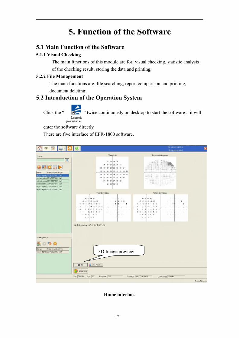
5.2 Introduction of the Operation System
Click the “ ” twice continuously on desktop to start the software,it will
enter the software directlyThere are five interface of EPR-1800 software.
Home interface
3D Image preview

20
Interface Bar: Back to Homeinterface, Back to Examination interface, User-define test interface, Printing, Systemsetting and About us
Patient info area: Recheck (the same eye of same patient) ,Edit, Delete(Selected patient data), All patient list, Last record
Waiting area: Register new patient, Start check, Edit, Delete
Testing interface
MonitoringWindow
Chin RestControl
Auto pupil monitoring – The system willadjust the chinrest automatically accordingto pupil monitoring-Doctors do not need tomonitor the whole testing after starting thetest
Gaze TrackingCurve

21
System setting interface
Double Name: For EU,USA and AUS etc market which need the first name andfamily name inputting.Gaze Tracking/EyeMove: Tick on for activating the gaze tracking function which willgenerate gaze tracking curve and Auto pupil measurement function.
Start test
Stop the test
Save the test result
Setting the parameter
Select test program
Test another eye
Diagnosis inputting

22
User-defined test interface
5.3 Several important programs and parameters of visual testingFirst choose a Testing Program (threshold test, screen test, special, custom). Once
the program is selected, go to the Parameter to choose a Strategy (full threshold,
auto threshold, fast auto threshold) accordingly.

23
6.Operation Steps
Operation Steps
6.1 Patient’s Preparation6.1.1 Perimeter examination should be done in the dark room, or the result is not
precise;6.1.2 Before examination, the patient should be relaxed and know the whole
examination process6.1.3 Automatic perimeter will adjust itself and control the testing stimulus light
automatically according to the operator’s requirement (Through the parameterssetup);
Note: As most of the ophthalmic patients are old men whose comprehension may benot very good, we should tell them the whole examining process carefully beforethe examination so that they will not be nervous and in a state of a totallyrelaxation during the process of examination. Since the patient should stare at thefixing spot for a long time and another hand will also became nervous, they willbe likely to feel fatigue. If this happened, the patient would not see things clearly,which may influence the examination result. So during the examination process,let the patient relax and tell them the right reaction. This is very important for asuccessful examination.
6.2 Doctor’s Preparation
The patient’s preparation The doctor’s Preparation
Patient’s examination
Treating after examination
Print report

24
6.2.1 Power on the perimeter and Enter into the perimeter system as the way in 5.2;Notes:After powering on the perimeter, it will take 3~4 minutes for aself-checking by running the stimulus lights automatically. This willguarantee the test accuracy. Do not treat it as an system error and do notenter into testing procedure while self-checking in processing, the systemwill not run correctly. Enter the testing only after self-checking finished.
6.2.2 Input the patient’s information;
6.2.3 Operator should inform patient the examination process before the examination:1) The patient should be familiar with the responder: demonstrate him the rightway of responding, the way of clicking the responder, and make him relax assoon as possible.
2) Demonstration him the fixing sight3) Cover the patient’s eye which will not be tested with an eye shroud.4) Put the patient’s jaw on the right side of the chin rest when examining the left
eye; put the patient’s jaw on the left of the chin rest when examining the righteye. If the patient testing Esterman binocular program, patient can either puttheir chin on left or right chinrest, but doctor need to adjust the cross inmonitoring window aimed at center of patient’s nose bridge.
5) Put his forehead on the ribbon of the forehead bracket slightly.6) The eyeball shall stare at the center fixation light, and cannot move, only
glance to perceive the stimulus light and respond to it by pressing theresponder

25
6.3 Starting Checking6.3.1 Before you start the test, you should Click the Register[ ] icon on the maininterface to setup the patient profile and input the info of patient, a patient profile willbe saved automatically after you clicking [Save] .
Patient with myopia, hyperopia and astigmatism will need to correct their diopterbefore starting the testing,our perimeter set trial lens holder for this function. Click onthe icon of [ ] and inputting patient’s real refractive diopter, then click on the[Auto Calc] to get the corrected lens you need to put on perimeter trial lens holder.
For example, if we inputting -5.0D under Sphere of Right eye, click on Auto Calc, thesystem will generate the corrected lens need to adapt for patient is -1.75D. Doctorshould test the patient with a -1.75D corrected lens.
6.3.2 After save patient data, you can find the patient record at [Waiting Room].

26
Click on the patient colume you wish to enter, and click on [ ] enter the testinginterfaceThe default testing program is 30-2,and strategy is auto threshold, if youwant to change to other program, click at the , select the programyou want to use as following image.
Or, if you want to change the strategy, click at and choose as below
Notes: The program and strategy will automatically resume to default value oncecurrently testing finished. System will not memory your last program and strategysetting. Operator need to proceed this process if default value needed to be

27
changed.
6.3.3 Then click to start testing. During the testing, doctor can use thefunction of [Auto Puil] monitoring so that do not need to monitor the whole processpersonally. The system will adjust the chinrest the headrest automatically.
6.3.4 After testing, you should save the test result by clicking at andthen you can diagnosis.
6.3.3 Click at the , choose the test report you need and preview. There are
Single, 3in1, and Overview test report optional.6.3.4 If your patient have come to you and test for several times, you should use theOverview report to see the progressing of patient.For doing more than one test with a same patient, you should click toproceed.For GPA analysis, at least 3 reports of (24-2 or 30-2) of same client shall begenerated before running this function.

28
6.3.5 Patient ListThrough this section, you can delete a patient profile by clicking the icon of ,andfind/recall a patient profile by clicking the icon of after you inputting thekeywords

29
7. Maintenance7.1 Common Problems
Breakdown Cause Treating methods
Can’t start system or
system doesn’t work
Failed to setup USB device Re-set USB device
Voltage isn’t enough or too
high
Replace power
Memory lost or damaged Insert again or replace the
computer memory card
Infect virus Use anti-virus software to
scan virus
Crashes while working or
show that the program is wrong.
Open too many
application programs,
re-start the computer
Hard disk is damaged Replace the hard disk
Nothing in the screen
when opening it
LCD monitor doesn’t display any
image
Properly connect the wire,
switch on power
The responder does
not work
Connection wire is damaged Replace the Connection
wire
Pressing button is damaged Replace the pressing key
The controlling card in the
stimulator does not work
Replace or maintain the
controlling card
7.2 Maintenance7.2.1 You should firstly turn on the power switch of the monitor and then turn on the
power switch of the main frame when opening the machine. When closing it,you should firstly log out, and then turn off the power supply of the monitorand the main frame.
7.2.2 Scan disk and arrange pieces in a certain period.7.2.3 Keep air clean, dry; use air-conditioner if possible7.2.4 If the instrument has not been used for a long time, you should supply power
for the main frame at intervals. (Usually three times a week, four hours onetime)
7.2.5 If there is something wrong with the instrument, please contact us immediately

30
or ask the special maintainers to maintain.Notes: You should clean the chin rest before and after each time you use it.
7.3 Fusing Parts:Model of fuse: φ5×20mm, T2A L250VReplace the fuse: Screw off the cover of fuse, replace it with a new good fuse,
then cover again (see the picture of the perimeter)

31
8. Interpretation of the report

32
1. False Negative Errors (False NEG Errors):False Negative errors occur when the patient does not respond to a suprathreshold
stimulus in an area where the threshold has already been measured. The interpretationof false-negative errors is not as clear as that of false-positive ones, because they canbe produced by a variety of sources. Visual field test results of patients whose falsenegative errors exceed 33% are not considered reliable.
2. False Positive Errors (False POS Errors):False positive errors occur if patients respond when no stimulus is presented. Forthe purposes of this study, we define a false positive response as randomlyoccurring, independent of stimulus presentation, and hence independent of anymonitored response window. The system will count it and if it’s over 20%, the testreport will be treated as unreliable. . Visual field test results of patients whosefalse positive errors exceed 33% are not considered reliable.
3. Fixation LossFixation losses occur when the patient’s eye wanders from the fixation target.Visual field test results of patients whose fixation losses exceed 20% are notconsidered reliable.
4. Percentage(Expressed as Letter P)
Less than 5 people within 100 people have this kind of visual situation
Less than 2 people within 100 people have this kind of visual situation
Less than 1 people within 100 people have this kind of visual situation
Less than 0.5 people within 100 people have this kind of visual situation
5. Total deviationThe difference between a patient’s threshold sensitivity and the age-corrected normalsensitivity from the perimeter’s internal normative database at each tested location ofthe visual field.
6. Pattern deviation (PD)

33
The localized loss at each tested point, after the removal of the effects of anygeneralized loss; pattern deviation decibel (dB) values are the total deviation valuesminus the general value.
7.Pattern standard deviation (PSD)It is a measurement of the degree which the shape of the patient's measured fieldor hill of vision departs from the "NORMAL" age-corrected reference field model.The value is expressed in decibels and any value of 2dB or greater will have a (P)value next to it indicating the significance of the deviation
8. Glaucoma Hemifield Test (GHT):It is for automated evaluation of single static threshold visual field test results inglaucoma. It is also constructed to detect field loss that is symmetric around thehorizontal meridian.
Outside normal limits. The GHT is described as “outside normal limits” whendifferences between a matched pair of corresponding zones exceeds thedifference found in 99% of the normal population, or when both members of apair of zones are more abnormal than 99.5% of the individuals with thenormative population.
Borderline. The GHT is described as borderline when matched pairs of zonesare abnormal at the 97th percentile within the normative database
General reduction of sensitivity. Visual Fields (VF) are described to havegeneralized reduction of sensitivity when both conditions for “outside normallimits” are not met, and the best region of the VF is depressed to a level at the99.5th percentile within individuals of the normative database.
Abnormally high sensitivity. The GHT is described as having abnormally highsensitivity when the overall sensitivity in the affected region of the VF isbetter than 99.5% of individuals within the normative population.
Within normal limits. VFs are described as being within normal limits whennone of the above conditions are met.
9.Bebie Curves:

34
Bebie curves. Bebie, or cumulative defect, curves are useful in detecting diffuse
depression of the visual field. The curve is a graphic ranking of the defect (the
difference between the measured threshold and the age-corrected normal threshold)
for each point in the visual field. The x axis represents the rank of the defect from
smallest (left side) to largest (right side). The y axis represents the magnitude of the
defect.
10.Mean Defects: (MD):The average of the examination value of all spots minus normal value, it shows thecondition of the patient’s vision sensitivity comparing with those of the same age.
11. Short Floating (SF):It shows the light sensitivity deviation appearing in one perimeter examinationprocess; it shows the reaction consistency in the course of examining. The biggerthe value is, the worse the cooperation the patient shows. The short wave willbecome height in the scope of abnormal visual field. When more scope in the visualfield become abnormal or the degree of abnormal increases, the whole wave willbecome higher.
12.Decibel (dB)In perimetry, the intensity of a stimulus expressed as 0.1 log-unit of attenuation of themaximal available stimulus; the higher the dB, the dimmer the stimulus intensity.
13.Fixation monitoringAssessing the ability of the patient to maintain gaze by the experimenter’sobservation.

35
9.Introduction of test parameter
1. Threshold test program:(1)30-2(recommend)Main applications:Common test,
glaucoma, optic nerve disease,retinal disease
Test Range:0°~30°Test points:76 dots
(2)24-2Main applications:Common test,
glaucoma, optic nerve diseaseTest Range:0°~24°Test points:54 dots
36
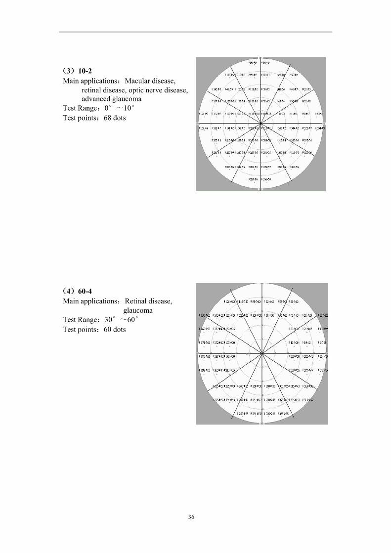
(3)10-2Main applications:Macular disease,
retinal disease, optic nerve disease,advanced glaucoma
Test Range:0°~10°Test points:68 dots
(4)60-4Main applications:Retinal disease,
glaucomaTest Range:30°~60°Test points:60 dots

37
(5) Macula program:Main applications:Macular diseaseTest Range:0°~5°Test points:16 dots
(6) Nasal step program:Main applications:GlaucomaTest Range:30°~50°Test points:14 dots

38
2. Screening test program
(1) C-40Main applications:Common testTest Range:0°~30°Test points:40 dots
(2) C-76Main applications:Common test,
glaucoma, optic nerve diseaseTest Range:0°~30°Test points: 76 dots

39
(3) FF-81Main applications:Full-field screening
test, retinal disease, glaucoma,optic nerve disease
Test Range:0°~60°Test points:81 dots
(4) FF-120Main applications:Full-field screening
test, retinal disease, glaucoma,optic nerve disease
Test Range:0°~60°Test points:120 dots

40
(5)FF-135Main applications:Full-field screening testTest Range:0°~55°,Temporal side 87°Test points:135 dots
3. Specialty test program(1)Esterman monocularMain applications:Driver test for single eyeTest Range:0°~60°,Temporal side 75°Test points:100 dots

41
(2) Esterman binocularMain applications:Driver test for double
eyesTest Range:Double temporal side 150°Test points:120 dots
(3) Superior 36Main applications:Screening upper
visual fieldMain applications:
upper visual field 60°Test points:36 dots

42
10. Declarations
We can provide you with the information of those parts need maintained.
1. We will provide maintenance and enquiry free for one life.
2. We will maintain the machine for free for one year since the date of purchasing if
the machine is operated according to the operation instruction.
3. During the maintenance, we will charge fee for the maintenance under the
following conditions
● Do not use, maintain, store the instruments according to operation instruction;
● Take apart or amend the instruments without the permission of us, which cause
damage;
● Damages is caused by accidents, use wrongly or caused by other major nature
factors.
● Please forgive us for not informing you if the design or the assigned type changes.

43