LED Pattern Projector - Smart Vision Lights integrate standard C-mount 2/3” lenses. Telecentric...
3
Smart Vision Lights • 1887 Holton Rd. • Suite D 353 • Muskegon, MI 49445 •Phone 231.722.1199 www.smartvisionlights.com SHARP UNIFORM LIGHT High Power LED Projector Driver built in – No External wiring to a driver PNP and NPN Strobe input Continuous operation or Strobe mode Dimmable via built in potentiometer Analog intensity via 0-10VDC signal SP30 Series Projector Light LED Pattern Projector Structured Light Standard patterns are available and custom patterns can be etched. Patterns can be changed. Line Grid Cross Multiple Lines Edge LED Projector can provide thinner lines with sharper edges and a more uniform illumination. Laser emitters have thicker lines with blurred edges. Non uniformity with decay at the ends along with speckle are present in laser emitters. Multiple LED Wavelengths UV to IR Available ANY SHAPE CAN BE PROJECTED
Transcript of LED Pattern Projector - Smart Vision Lights integrate standard C-mount 2/3” lenses. Telecentric...
Smart Vision Lights • 1887 Holton Rd. • Suite D 353 • Muskegon, MI 49445 •Phone 231.722.1199 www.smartvisionlights.com
SHARP UNIFORM LIGHT
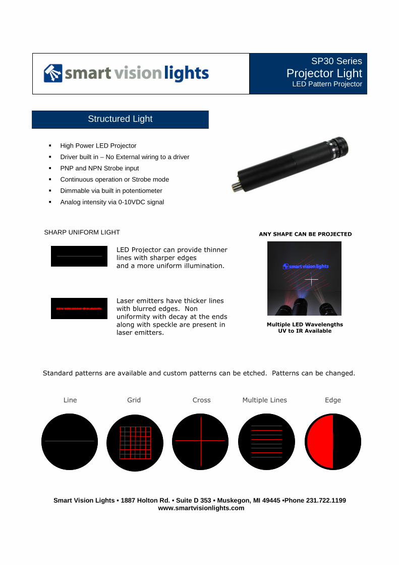
� High Power LED Projector
� Driver built in – No External wiring to a driver
� PNP and NPN Strobe input
� Continuous operation or Strobe mode
� Dimmable via built in potentiometer
� Analog intensity via 0-10VDC signal
SP30 Series Projector Light
LED Pattern Projector
Structured Light
Standard patterns are available and custom patterns can be etched. Patterns can be changed.
Line Grid Cross Multiple Lines Edge
LED Projector can provide thinner
lines with sharper edges
and a more uniform illumination.
Laser emitters have thicker lines
with blurred edges. Non
uniformity with decay at the ends
along with speckle are present in
laser emitters.
Multiple LED Wavelengths
UV to IR Available
ANY SHAPE CAN BE PROJECTED
Joe
Text Box
Smart Vision Lights · 2359 Holton Road · Muskegon, MI 49445 · Phone 231.722.1199

Smart Vision Lights • 1887 Holton Rd. • Suite D 353 • Muskegon, MI 49445 •Phone 231.722.1199 www.smartvisionlights.com
Sq
ua
re A
rea
of
Illum
ina
tion
Projectors integrate standard C-mount 2/3” lenses. Telecentric lenses can also be used for
telecentric pattern projection. Projector lenses and pattern sizes with distances are listed in
the chart below. Chart is approximations due to differences of lens manufacturers.
Working Distance
100mm 150mm 200mm 300mm 400mm 500mm 600mm 750mm 1000mm 1500mm 2000mm
60mm2 25 50
100mm2 8 12 16 25 35 35 50 50
150mm2 6 8 12 16 25 25 35 35 50 75
200mm2 6 8 12 16 16 25 25 35 50 100
300mm2 6 8 12 12 16 16 25 35 50
400mm2 6 8 8 12 12 16 25 35
500mm2 6 8 12 16 25 25
Number in box represents the focal length of lens (example - 6 is a 6mm focal length lens)
1 = 24VDC 2 = NPN STROBE 3 = GND 4 = PNP STROBE 5 = 0-10VDC Analog
BROWN WHITE BLUE BLACK *GRAY (GREEN/YELLOW)
Standard M12 mating cable color code:
* 5 pin Standard M12 mating cable must be used: +VDC must be connected to pin 5 if Analog 0-10 VDC is not used.
Electrical Input Voltage - 24 VDC +/- 10% Maximum 12 Watts
Strobe PNP ► +5VDC or greater to activate. NPN ► GND (<1VDC) to activate
Strobe Mode
The Light will operate in either continuous or strobe mode. In strobe mode, the output pulse width will track the pulse width of the strobe pulse.
Analog Intensity The output is adjustable from 10%-100% of brightness by a 0 -10 VDC signal
Dimmable The output is manually adjustable from 10%-100% of brightness by potentiometer
Continuous Mode Light will be in continuous mode by leaving signal on strobe input
SP30 – XXX – XXX Product Family:
Projector Light 30mm Barrel
Pattern: Line – LN Grid– GD Cross Hair – CH Contact us for more details
─» Part Number Key Color :
625 – Red White – WHI 470 – Blue 530 – Green Contact us for other wavelengths
Joe
Text Box
Smart Vision Lights · 2359 Holton Road · Muskegon, MI 49445 · Phone 231.722.1199
Smart Vision Lights • 1887 Holton Rd. • Suite D 353 • Muskegon, MI 49445 •Phone 231.722.1199 www.smartvisionlights.com
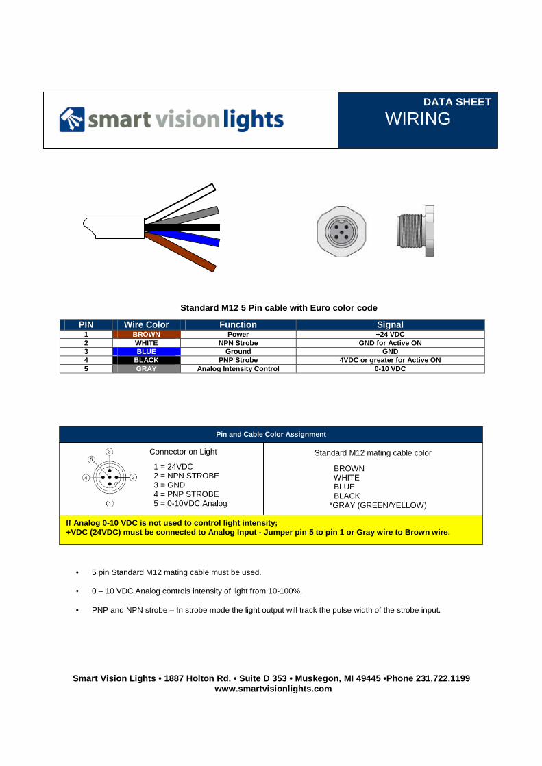
• 5 pin Standard M12 mating cable must be used.
• 0 – 10 VDC Analog controls intensity of light from 10-100%.
• PNP and NPN strobe – In strobe mode the light output will track the pulse width of the strobe input.
PIN Wire Color Function Signal 1 BROWN Power +24 VDC 2 WHITE NPN Strobe GND for Active ON 3 BLUE Ground GND 4 BLACK PNP Strobe 4VDC or greater for Active ON 5 GRAY Analog Intensity Control 0-10 VDC
Standard M12 5 Pin cable with Euro color code
DATA SHEET
WIRING
Pin and Cable Color Assignment
1 = 24VDC 2 = NPN STROBE 3 = GND 4 = PNP STROBE 5 = 0-10VDC Analog
BROWN WHITE BLUE BLACK *GRAY (GREEN/YELLOW)
Standard M12 mating cable color
If Analog 0 -10 VDC is not used to control light intensity; +VDC (24VDC) must be connected to Analog Input - Ju mper pin 5 to pin 1 or Gray wire to Brown wire.
Connector on Light
Joe
Text Box
Smart Vision Lights · 2359 Holton Road · Muskegon, MI 49445 · Phone 231.722.1199