LED FLASHING SYSTEM FOR APPROACH, REIL, CGL...LED Light Emitting Diode ... EASA European Aviation...
44
www.ocem.com [email protected] LED FLASHING SYSTEM FOR APPROACH, REIL, CGL INSTRUCTION MANUAL FOR USE AND MAINTENANCE Document name UT-MT-0893_EN Edition 01/08/2018 Edited by ALAN, EBER, MCAS Checked by MMAZ Via della Solidarietà, 2/1 40056 Valsamoggia, Loc. Crespellano Bologna - ITALY
Transcript of LED FLASHING SYSTEM FOR APPROACH, REIL, CGL...LED Light Emitting Diode ... EASA European Aviation...

www.ocem.com
LED FLASHING SYSTEM FOR APPROACH, REIL, CGL
INSTRUCTION MANUAL FOR USE AND MAINTENANCE
Document name UT-MT-0893_EN
Edition 01/08/2018
Edited by ALAN, EBER, MCAS
Checked by MMAZ
Via della Solidarietà, 2/1
40056 Valsamoggia, Loc. Crespellano
Bologna - ITALY

THIS COPY IS NOT SIGNED SINCE IT IS FILED AND DELIVERED BY MEANS OF THE AUTOMATIC KNOWLEDGE MANAGEMENT SYSTEM
(IT CAN BE SIGNED ON REQUEST). THIS DOCUMENT AND THE DATA CONTAINED HERE IN, IS PROPRIETARY PROPERTY AND SHALL
NOT BE DUPLICATED, USED OR DISCLOSED - IN WHOLE OR IN PART - FOR ANY POURPOSE WITHOUT WRITTEN CONSENT OF OCEM.

LED FLASHING SYSTEM FOR APPROACH, REIL, CGL
INSTRUCTION MANUAL FOR USE AND MAINTENANCE
Document UT-MT-0893 _EN Page 3 of 44 Edition 01/08/2018
INDEX
1 INTRODUCTION ................................................................................................... 5
1.1 Safety Instructions ............................................................................................................. 5
1.2 Icons used in the manual ................................................................................................ 6
1.3 Abbreviations and terms ................................................................................................. 7
2 DESCRIPTION ....................................................................................................... 8
2.1 Applications and compliances ....................................................................................... 8
2.2 LED Flashing System overview ......................................................................................... 8 2.2.1 Flash Master Control Unit FMCU ................................................................................................... 9 2.2.2 Touch Pad ...................................................................................................................................... 10 2.2.3 Flash Field Unit (FFU) ...................................................................................................................... 11 2.2.4 Inset light fixture LIFL ...................................................................................................................... 11 2.2.5 Elevated light fixture LEFL ............................................................................................................. 12 2.2.6 Installation ....................................................................................................................................... 13
3 USE OF THE SYSTEM ........................................................................................... 13
3.1 Touch Pad Main Page .................................................................................................... 13
3.2 Configuration .................................................................................................................. 14 3.2.1 Configuration Parameters ........................................................................................................... 14 3.2.2 How to modify IP Address ............................................................................................................ 17 3.2.3 Configuration procedure of a new Flash Field Unit (FFU) ..................................................... 18 3.2.4 Configuration procedure of a whole new Flash System ....................................................... 20 3.2.5 Uninstallation procedure of a Flash Field Unit (FFU) ................................................................ 21 3.2.6 Commands .................................................................................................................................... 22
3.3 Diagnostic ....................................................................................................................... 23
4 MAINTENANCE .................................................................................................. 25
4.1 Flash Master Control Unit (FMCU) .................................................................................. 25 4.1.1 Periodical maintenance .............................................................................................................. 25 4.1.2 Master board replacement ........................................................................................................ 26 4.1.3 Touch Pad Replacement ............................................................................................................ 27 4.1.4 Troubleshooting ............................................................................................................................. 28
4.2 Flash Field Unit (FFU) ....................................................................................................... 29 4.2.1 FFU Replacement .......................................................................................................................... 29
4.3 Elevated light fixture LEFL ............................................................................................... 31 4.3.1 Periodical Checks ......................................................................................................................... 31 4.3.2 Light fixture replacement ............................................................................................................ 31 4.3.3 Electronic board replacement .................................................................................................. 32 4.3.4 LED module replacement ........................................................................................................... 33 4.3.5 Cable lead with plug replacement .......................................................................................... 34 4.3.6 LEFL Troubleshooting ..................................................................................................................... 36
4.4 Inset light fixture LIFL ....................................................................................................... 37

LED FLASHING SYSTEM FOR APPROACH, REIL, CGL
INSTRUCTION MANUAL FOR USE AND MAINTENANCE
Document UT-MT-0893 _EN Page 4 of 44 Edition 01/08/2018
4.4.1 Periodical Checks ......................................................................................................................... 37 4.4.2 Removing and opening the light unit from the base ............................................................ 38 4.4.3 Prism Cleaning and replacement ............................................................................................. 40 4.4.4 LED module replacement ........................................................................................................... 41 4.4.5 Cable lead with plug replacement .......................................................................................... 41 4.4.6 Pressure valve replacement ....................................................................................................... 42 4.4.7 LIFL Troubleshooting ...................................................................................................................... 42
5 SPARE PARTS ...................................................................................................... 43
6 APPENDIX .......................................................................................................... 44
INDEX OF FIGURES
Figure 1. FMCU external components and interfaces ..................................................................... 9 Figure 2. Touch Pad rear description ................................................................................................ 10 Figure 3. LIFL exploded view ............................................................................................................... 11 Figure 4. LEFL exploded view .............................................................................................................. 12 Figure 5. Master board replacement ................................................................................................ 26 Figure 6. Touch Pad replacement ..................................................................................................... 27 Figure 7. FFU replacement .................................................................................................................. 30 Figure 8. LEFL Light fixture replacement ............................................................................................ 31 Figure 9. LEFL Electronic Board replacement .................................................................................. 32 Figure 10. LEFL Led module replacement .......................................................................................... 33 Figure 11. Lower Cover with Pressure Valve....................................................................................... 39 Figure 12. Prism replacement components ....................................................................................... 40 Figure 13. LED Module Replacement components ......................................................................... 41 Figure 14. PAFLC0001.01 ........................................................................................................................ 44

LED FLASHING SYSTEM FOR APPROACH, REIL, CGL
INSTRUCTION MANUAL FOR USE AND MAINTENANCE
Document UT-MT-0893 _EN Page 5 of 44 Edition 01/08/2018
1 INTRODUCTION
1.1 Safety Instructions
The following section contains important safety information that you must follow when install, use
and repair the apparatus.
To a proper and safe use of the apparatus:
- Refer to IEC 61821 (Electrical installations for lighting and beaconing of aerodromes - Maintenance
of aeronautical ground lighting circuits) for safety precaution;
- Observe precaution for low voltage equipment (230VAC);
- Do not carry out any installation or maintenance operation on apparatus connected to energized
circuits. Remove power supply to avoid contact with voltage or current sources;
- For no reason the protections and the safety devices must be removed;
- Read safety instruction for all used equipment and follow the safety instructions of your company,
government or other regulatory agencies.
Different use of the apparatus than described in this manual may result in personal injury,
death, or property and equipment damage. Use the apparatus only as described in the
manual. WARNING
Before installation or maintenance read carefully the apparatus manuals.
MANUALS
Only qualified personnel should operate on the apparatus. The qualified personnel must be
physically capable and well informed and trained on the risks related to the electricity and
low voltage apparatus. During any operation on apparatus, cables or other equipment, the
personnel should respect the safety rules.
The maintenance staff must be aware of the criteria to prevent the risk of electric shock and
resuscitation techniques. PERSONNEL
Before any access, inspection or intervention be sure to have switched-off the system. It is
also recommended to remove the power supply to the system (by opening the circuit
breaker/switch in the main distribution board feeding the Flash Master Control Unit). Then
wait discharge time (at least 5 minutes), ground carefully the system, and check for voltage
presence before accessing. WARNING
During the installation or maintenance operations on the apparatus:
- Follow the general safety rules;
- Make sure that environmental conditions, means of transports or animals will not damage the
electrical system;
- Don’t touch energized voltage or current sources;
- Pay attention when operate with electrical equipment in presence of high humidity environment
- Use unapproved equipment will void the warranty.

LED FLASHING SYSTEM FOR APPROACH, REIL, CGL
INSTRUCTION MANUAL FOR USE AND MAINTENANCE
Document UT-MT-0893 _EN Page 6 of 44 Edition 01/08/2018
In case of removal of safety device, restore them as soon as possible.
Do not operate on the apparatus if it is not working properly or alarms are enable.
For maintenance, use only approved spare parts; using unapproved or modified spare parts may
create safety hazards and invalidate the warranty.
This equipment complies with the requirements of European regulations for the CE mark.
The user has to respect all prescriptions reported in this document.
This equipment complies with the requirements of the EEC directives 2004/108/EEC and
2006/95/EEC with regard to “Electromagnetic Compatibility” and “Low Voltage Electrical
Apparatus” respectively. CE MARK
OUT OF SERVICE
In case of dismantling, decommissioning, destruction, disposal, the user shall follow all the required
precautions for component and material elimination, according to local rules and applicable law.
1.2 Icons used in the manual
GENERAL DANGER
ELECTRIC DISCHARGES
DO NOT INTERVENE MANUALLY
READ THE ATTACHED DOCUMENTATION
AUTHORIZED PERSONNEL ONLY
CE MARK
ADDITIONAL INFORMATION
QUALIFIED TECHNICIAN

LED FLASHING SYSTEM FOR APPROACH, REIL, CGL
INSTRUCTION MANUAL FOR USE AND MAINTENANCE
Document UT-MT-0893 _EN Page 7 of 44 Edition 01/08/2018
ELECTRICALLY DISCONNECT BEFORE CARRYING OUT WORK OR REPAIRS
GENERAL OBBLIGATION
1.3 Abbreviations and terms
LED Light Emitting Diode
ICAO International Civil Aviation Organization
EASA European Aviation Safety Agency
PMMA Polymethylmethacrylate
CCR Constant Current Regulator
FAA Federal Aviation Administration
FMCU Flash Master Control Unit
FFU Flash Field Unit

LED FLASHING SYSTEM FOR APPROACH, REIL, CGL
INSTRUCTION MANUAL FOR USE AND MAINTENANCE
Document UT-MT-0893 _EN Page 8 of 44 Edition 01/08/2018
2 DESCRIPTION
2.1 Applications and compliances
The LED Flashing System can be used as:
- Approach Sequential Flash Light (SFL);
- Runway Threshold Identification Light (RTIL);
- Circling Guidance Light (CGL);
- A combination of two or three parts mentioned above, managed by a single FMCU (that have to
flash in a coordinated manner and at the same frequency).
The Flashing System is compliant to:
- ICAO Annex 14 Vol.1;
- ICAO doc 9157 - Aerodrome Design Manual - Parts: 4, 5 and 6;
- EASA CS-ADR-DSN;
- FAA Engineering Brief No67;
- IEC TS 61827;
- NATO-STANAG 3316;
- CASA MOS 139;
2.2 LED Flashing System overview
Typically, the LED Flashing System is composed by:
- Nr. 1 Flash Master Control Unit (FMCU), including a Touch Pad for local HMI and an interface to
remote system (ALCMS);
- Nr. N Flash Field Units (FFU);
- Nr. N elevated/inset light fixture (one fixture for each FFU);
In addition, some accessories can be ordered (separately):
- Connectors to realize electrical junctions;
- Other installation equipment (frangible couplings, poles, shallow bases, etc.).
LED FLASHING SYSTEM FOR APPROACH, REIL, CGL
INSTRUCTION MANUAL FOR USE AND MAINTENANCE
Document UT-MT-0893 _EN Page 9 of 44 Edition 01/08/2018
2.2.1 Flash Master Control Unit FMCU
The FMCU is the interface between the control system and the Flashing System. Its main functions
consist in supplying power to the flashing units on the field and in controlling and monitoring the
entire system.
The FMCU communicate through a Power line communication to the Flashing System (all the FFUs)
for the following functions:
- Control and monitoring the Flashing System from both local interface (Touch Pad) and remote
system (ALCMS);
- Regulate the Flashing System parameters, as brightness level and flashing frequency of the light
fixtures;
- Synchronize all the FFU;
- Receive diagnostic information as LED status, faults etc. from each Flash Field Unit (FFU).
FMCU characteristics:
- Power supply: Single Phase, 230 VAC (+/-10%), 50-60 Hz;
- IP Class: IP43
- Electrical Protection: Input and Output Circuit Breaker
- Environment Temperature: -10°C to +50°C
- Installation: Metal Housing Wall Mounted
- Humidity (not condensed): 20-90%
- Max Altitude: 2500 m
- Dimensions: 50 x 30 x 25 cm
- Weight: 15 kg
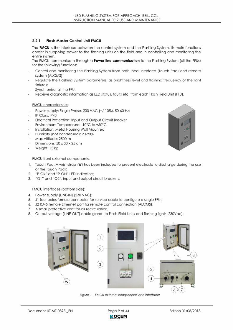
FMCU front external components:
1. Touch Pad. A wrist-strap (W) has been included to prevent electrostatic discharge during the use
of the Touch Pad);
2. “P-OK” and “P-ON” LED indicators;
3. “Q1” and “Q2”, input and output circuit breakers.
FMCU interfaces (bottom side):
4. Power supply (LINE-IN) (230 VAC);
5. J1 four poles female connector for service cable to configure a single FFU;
6. J2 RJ45 female Ethernet port for remote control connection (ALCMS);
7. A small protective vent for air recirculation;
8. Output voltage (LINE-OUT) cable gland (to Flash Field Units and flashing lights, 230Vac);
Figure 1. FMCU external components and interfaces

LED FLASHING SYSTEM FOR APPROACH, REIL, CGL
INSTRUCTION MANUAL FOR USE AND MAINTENANCE
Document UT-MT-0893 _EN Page 10 of 44 Edition 01/08/2018
FMCU internal components:
- OCEM Master board (F316);
- Inductor L1 and OCEM Input Filter Board (F340);
- X1 and X2 Input & Output terminal board;
- Q1 and Q2 Input & Output circuit breakers (one to protect the power supply
line and one to protect the FMCU in case of short circuit or overcurrent
events);
- Fuses F1 and F2 (to protect against short circuits inside the auxiliary power
supply)
- Fuse F3 (to protect the panel board against short-circuit of LED “P-ON” light)
- Fuses F4 and F5 (to protect the panel board against short-circuit in the J1 /
Service Cable / FFU under programming)
- T1 and T2 power supply (to feed the Touch Pad and the Master board).
2.2.2 Touch Pad
The Touch Pad is a touch screen interface, located in the FMCU cabinet.
The main functions of the Touch Pad are:
- setting up the configuration parameter of the Flashing System directly
from the FMCU;
- providing commands to the Flashing System;
- installing and de-installing new FFU units;
- providing diagnostic information about every flashing unit on the field.
Touch Pad Rear Description
1. Ethernet
2. RS-485
3. Rotary Switch
o Position 0 (normal usage mode): Run
o Position 1: Update OS
o Position 9: Update AP
4. Micro USB
Figure 2. Touch Pad rear description
The circuit breaker is not equipped with differential protection. It is customer responsibility to
provide this protection in the main power supply line energizing the regulator.
WARNING

LED FLASHING SYSTEM FOR APPROACH, REIL, CGL
INSTRUCTION MANUAL FOR USE AND MAINTENANCE
Document UT-MT-0893 _EN Page 11 of 44 Edition 01/08/2018
2.2.3 Flash Field Unit (FFU)
The main Flash Field Unit (FFU) functions are:
- Receiving and executing commands from the FMCU;
- Supplying power to the associate elevated/inset light fixture;
- Provide diagnostic information (LED status, faults etc.) to the FMCU.
FFU characteristics:
- Power supply (from FMCU): Single Phase, 230 VAC(+/-10%), 50-60 Hz
- IP Class: IP67
- Environment Temperature: -40°C to +55°C
- Max. Altitude: 2500 m
- Dimensions: 22 x 25 x 12 cm
2.2.4 Inset light fixture LIFL
The LIFL fixture is a 12’’ inset LED flash light, unidirectional steady burning
type.
Each light assembly installed in the field consists of a removable fixture
and a shallow base receptacle (separately provided). The fixture is
waterproof and designed to withstand aircraft impact and rollover
loads without damage.
1. Dome with prisms and gaskets;
2. O-Ring for dome (external);
3. O-Ring for dome (internal);
4. O-Ring for lower cover;
5. Reflector;
6. LED module;
7. Lower cover with electronic, plug
and valve;
8. Valve for water tightness test;
9. FAA L-823 plug;
10. Prism Gasket;
11. Prism;
12. Prism holder gasket;
13. Mounting plate;
Figure 3. LIFL exploded view

LED FLASHING SYSTEM FOR APPROACH, REIL, CGL
INSTRUCTION MANUAL FOR USE AND MAINTENANCE
Document UT-MT-0893 _EN Page 12 of 44 Edition 01/08/2018
2.2.5 Elevated light fixture LEFL
The LEFL fixture is an elevated LED flash light, unidirectional steady burning
type.
Each light assembly consists of a body balanced on a special support for
proper and accurate horizontal and vertical aiming. The support allows the
direct mounting on the breakable coupling or on the top of 60 mm dia
supporting pole.
1. Cover
2. Cover gasket
3. LED module support
4. LED module support gasket
5. LED module
6. Lens array for LED module
7. Body
8. Transparent front protection gasket
9. Transparent front protection
10. Transparent front protection holder plate (painted white)
11. Vertical aiming adjusting device
12. Special support
13. Power connector
14. Electronic interface
Figure 4. LEFL exploded view

LED FLASHING SYSTEM FOR APPROACH, REIL, CGL
INSTRUCTION MANUAL FOR USE AND MAINTENANCE
Document UT-MT-0893 _EN Page 13 of 44 Edition 01/08/2018
2.2.6 Installation
For detailed information about the installation of the Flashing System on the field,
see the OCEM UT-MT-0892 Installation Manual.
NOTE
3 USE OF THE SYSTEM
The LED Flashing System is provided with some pre-configured options that can be changed after
the installation. The following paragraphs describe how to configure and use the system.
3.1 Touch Pad Main Page
1. Software version;
2. IP Address: the device is based on Modbus/TCP protocol. To set IP Address see the paragraph
3.2.2.
3. Serial Status: it reports the state of communication between the Touch Pad and the master board
based on RS-485 protocol
o Green light indicates that the communication is established;
o Red light indicates a problem in the communication.
Every time the operator uses the Touch Pad, he have to wear the wrist-strap against
electrical discharge that can be provided to the panel.
WARNING

LED FLASHING SYSTEM FOR APPROACH, REIL, CGL
INSTRUCTION MANUAL FOR USE AND MAINTENANCE
Document UT-MT-0893 _EN Page 14 of 44 Edition 01/08/2018
3.2 Configuration
3.2.1 Configuration Parameters
1. Polling Period: time interval in seconds between two requests of FFU status from the Touch Pad to
the Master board. The Master reports:
- If the units are working correctly;
- If there are active warnings;
- If the units are correctly calibrated;
- If the units are correctly configured.
To change the value: press at the corresponding bar and swipe with the finger.
For more precise adjustment, press on the bar and then uses the UP/DOWN button (A). Polling Period
is defined in the range 5 – 240 sec.
Press “Apply” to confirm the changes; press “Undo” to cancel the changes.
2. Flash Total Number: total number of FFU of the system. Change as described in 1, so press “Apply”
or “Undo”. The maximum possible value is 64.
3. Flashing Group Total Number: indicates how many groups of simultaneously flashing units are
present. Clearly, this value cannot be greater than the flash total number. Change as described
in 1, so press “Apply” or “Undo”;
The following setting procedure shall be done before the configuration of a new FFUs. This
operation is typically performed in the factory and the FFUs are provided as already
configured. In this case all the FFUs are labelled according their IDs, groups and position in
the flashing sequence. INFO
After the first configuration of the FFUs, every time the parameters are changed, the new
configuration values are automatically distributed to all the FFUs connected to the system.
INFO

LED FLASHING SYSTEM FOR APPROACH, REIL, CGL
INSTRUCTION MANUAL FOR USE AND MAINTENANCE
Document UT-MT-0893 _EN Page 15 of 44 Edition 01/08/2018
4. Frequency Setup: indicates the frequency of the main power supply line of the system. Select the
frequency in Hz used in the country of installation (50Hz or 60Hz). Press “Apply” to confirm the
selection; press “Back” to return to the configuration view.
By pressing the right arrow, the frame for the installation of a new FFU appears on the Touch Pad.
5. Flash unit’s ID: ID of the FFU;
6. Unit’s flashing group; indicates
the group of lights to which the
unit ID belongs;
7. Normal: select “Normal” to
install a simple FFU;
8. Repeater (no light): select
“Repeater (no light)” to install an
FFU box without any associated
flashing fixture. This configuration
can be beneficial in case of
long cable distances between
the FMCU and the first FFU of the
chain;
9. Repeater: select “Repeater” to
install an FFU used also as SMART
repeater for some kind of
messages;
After the installation of a repeater
FFU (with or without associated
flashing light), the buttons (7), (8),
and (9) are disabled and they
cannot be selected for other FFUs.
In fact, it is possible to configure
only one FFU as a repeater within
the system. To unlock the buttons
and select another FFU as a
repeater, the current repeater
must be first uninstalled.

LED FLASHING SYSTEM FOR APPROACH, REIL, CGL
INSTRUCTION MANUAL FOR USE AND MAINTENANCE
Document UT-MT-0893 _EN Page 16 of 44 Edition 01/08/2018
10. Elevated: select “Elevated” to install an FFU associated to an elevated light fixture;
11. Inset: select “Inset” to install an FFU associated to an inset light fixture;
12. RTIL: flag “RTIL” box to install a RTIL FFU;
Units set as RTIL flash simultaneously. In case of failure of one RTIL light, all the units marked as RTIL will
switch off to guarantee consistency of visual information, according to ICAO requirements. If the
RTIL box is checked, the “Unit’s flashing group” box changes color, to highlight that the RTIL group
must be unique within the system.
13. Install: after all the parameters are set for the considered FFU, pressing the button the installation
starts;
14. Calibrate: when the color is orange, indicates that a calibration is in progress. When the color is
green, indicates that the calibration is successfully completed;
15. Uninstall: uninstall an FFU already installed.

LED FLASHING SYSTEM FOR APPROACH, REIL, CGL
INSTRUCTION MANUAL FOR USE AND MAINTENANCE
Document UT-MT-0893 _EN Page 17 of 44 Edition 01/08/2018
3.2.2 How to modify IP Address
To change the IP Address, follow the steps described below:
1. From the main page, click on the IP Address (A)
2. In the new page, click on the empty spaces (B) or (C) to select one of them
3. Use the numeric keypad to write the new IP Address
4. Press Reset (D) to erase the content of the two cell (B) and (C)
5. Press Back (E) to return to the main page or Confirm (F) to confirm the new IP Address
When the new IP Address is set, all the buttons in the page are disabled and the message (G)
appears.
It is necessary to power off and restart the FMCU to apply the modification.

LED FLASHING SYSTEM FOR APPROACH, REIL, CGL
INSTRUCTION MANUAL FOR USE AND MAINTENANCE
Document UT-MT-0893 _EN Page 18 of 44 Edition 01/08/2018
3.2.3 Configuration procedure of a new Flash Field Unit (FFU)
In order to configure a new FFU, it is required that all the other FFUs connected to the system are
already configured. In other words, during the configuration procedure, only one new (i.e. not-yet-
configured) FFU can be visible to the FMCU at any time.
To configure a new FFU that has been connected to the system, follow the steps described below.
1. Open the “Configuration parameters” frame from the main page of the Touch Pad by pressing
the “Configuration” button as described in the paragraph 3.2.1;
2. Press the right arrow to visualize to the page for the installation of a new flash unit;
3. Select “Normal” (F) to install an FFU without activate repeater function;
4. Select “Elevated” or “Inset” (G) to install an elevated/inset FFU. Flag “RTIL” to configure the FFU as
a RTIL unit;
5. Set the ID of the FFU using the arrows (H);
6. Set the flashing group of belonging of the FFU using the arrows (I).

LED FLASHING SYSTEM FOR APPROACH, REIL, CGL
INSTRUCTION MANUAL FOR USE AND MAINTENANCE
Document UT-MT-0893 _EN Page 19 of 44 Edition 01/08/2018
Then the button “Install” becomes green: this means that the FFU has communicated to the Master
board its presence in the system with positive result.
7. Press “Install”(J);
The button “Install” becomes orange and a first acoustic signal is emitted. This indicates that
configuration parameters have been sent to the FFU.
Now the button “Calibrate” becomes orange. This indicates that a calibration is ongoing. The unit
starts to flash for a few seconds.
The button “Calibrate” become green and the system emits a second acoustic signal, confirming
that the operation is successfully completed.
When the installation is successfully completed, “Flash unit’s ID” and “Unit’s flashing group” becomes
green. This indicates to the user that the FFU is already installed and configured.
If the calibration does not terminate correctly, the button “Calibrate” becomes red and a
second acoustic signal of error is emitted.
This can happen for two reasons:
- Some units of the system are not correctly connected to the power supply;
- The FFU is not able to communicate with the Master board of the FMCU.
If this happen, check the electrical connections of the units in the system and try
again. INFO

LED FLASHING SYSTEM FOR APPROACH, REIL, CGL
INSTRUCTION MANUAL FOR USE AND MAINTENANCE
Document UT-MT-0893 _EN Page 20 of 44 Edition 01/08/2018
3.2.4 Configuration procedure of a whole new Flash System
1. Set the Polling Value (A) as described in the paragraph 3.2.1;
2. Set the number of flash unit (B) as described in the paragraph 3.2.1;
3. Set the flashing group (C) as described in the paragraph 3.2.1;
4. Set the frequency (D) as described in the paragraph 3.2.1;
5. Keeping the FMCU powered (Q1 = ON), open the circuit breaker “Q2” to power down the lights in
the field;
6. Insert the supplied service cable GEMMN0056 in the connector “J1” of the FMCU;
7. Connect the other end of the service cable to the 5 pole connector of the new FFU;
8. Press the arrow (E);
9. Install the new FFU from the Touch Pad as described in the paragraph 3.2.3;
10. Disconnect the service cable from both the ends;
11. Repeat the steps above starting from point 9 for all the FFUs that need to be configured.
At this point, the configured FFUs can be connected to the power line in the field. Now, It’s possible
to:
12. Close the circuit breaker “Q2”;
13. Power up the lights in the field by using commands described in the paragraph 3.3.
Switch off the circuit breaker Q2 is important to guarantee electrical safety for the operators
and to avoid functional problems during the installation of the new FFU.
WARNING
5 POLE CONNECTOR

LED FLASHING SYSTEM FOR APPROACH, REIL, CGL
INSTRUCTION MANUAL FOR USE AND MAINTENANCE
Document UT-MT-0893 _EN Page 21 of 44 Edition 01/08/2018
3.2.5 Uninstallation procedure of a Flash Field Unit (FFU)
To erase the configuration of an already installed FFU, follow the steps below:
1. Open the “Configuration parameters” frame from the main page of the Touch Pad by pressing
the “Configuration” button as described in the paragraph Errore. L'origine riferimento non è stata
trovata.;
2. Press the right arrow (E) to visualize to the page for the installation of a new flash unit;
3. Select the ID of the FFU to be uninstalled (L);
4. Press the uninstall button (K).
The system emits an acoustic signal. The button “Calibrate” becomes black, as well as the “Flash
unit’s ID” and “Unit’s flashing group” values.

LED FLASHING SYSTEM FOR APPROACH, REIL, CGL
INSTRUCTION MANUAL FOR USE AND MAINTENANCE
Document UT-MT-0893 _EN Page 22 of 44 Edition 01/08/2018
3.2.6 Commands
From the main page of the Touch Pad, press the “Commands” button to go to the relative page.
The control panel of the flashing system is visualized.
It is possible to set the following parameters:
- Flash Period: flashing frequency (every second / half second);
- Flash Intensity: flashing intensity (high and compliant to the standard ICAO / normal);
- Flash Level: flashing brightness level (high – level 1 / medium – level 2 / low – level 3 / OFF).
“Back” button (4) to return to the main frame.

LED FLASHING SYSTEM FOR APPROACH, REIL, CGL
INSTRUCTION MANUAL FOR USE AND MAINTENANCE
Document UT-MT-0893 _EN Page 23 of 44 Edition 01/08/2018
3.3 Diagnostic
From the main page of the Touch Pad, press the
“Diagnostic” button to go to the corresponding
page. A grid that offer a synoptic of all the units
installed is visualized.
The system can assign the following
specifications to every unit:
- IN: inset FFU;
- R: Repeater FFU;
If the FFU is an Elevated unit, no symbol is
visualized in the grid.
For every installed unit, the corresponding group
is specified with a number reported in the right-
bottom side of the circle.
Moreover, for every unit, the system reports the current status, according to the colors:
- GREEN: FFU works properly;
- YELLOW: FFU reports a warning;
- RED: FFU reports an error;
By clicking one of the colored circles representing the installed units, it is possible to visualize the
diagnostic frame of every single unit, where are reported the parameter of that unit. The same frame
can be recalled by pressing the “Flash Unit Status” button on the Touch Pad and selecting the unit
ID of interest.
After a few seconds, during which the system polls the FFU and the indication “Value acquisition…”
(1) is visible, values previously set and other useful information for the user appears on the screen.
The information visualized are the following:
2. Flash Unit ID;
3. Flashing group of the flash unit;
4. Firmware version of the PIC
(Programmable Interrupt
Controller);
5. Firmware version of the CPU;
6. Unit status;
7. Current value (Ampere);
8. Temperature (Celsius);
9. Voltage (Volts);
10. Auxiliary Voltage (Volts);
11. Forward Voltage (Volts);

LED FLASHING SYSTEM FOR APPROACH, REIL, CGL
INSTRUCTION MANUAL FOR USE AND MAINTENANCE
Document UT-MT-0893 _EN Page 24 of 44 Edition 01/08/2018
Using the arrows (12) is possible to go directly from the status frame of one FFU to another one.
In the case the voice “Status” (6) reports a condition of error, it’s necessary:
- Resolve the problem of the unit restoring the condition of normal operation (the status
visualized will be still alarmed)
- Press the button “Reset Alarm” (13); status becomes “Correctly working”;
“Back” button (14) to return to the frame of the synoptic of the FFUs.

LED FLASHING SYSTEM FOR APPROACH, REIL, CGL
INSTRUCTION MANUAL FOR USE AND MAINTENANCE
Document UT-MT-0893 _EN Page 25 of 44 Edition 01/08/2018
4 MAINTENANCE
In order to ensure maximum Flashing System life, the installed units should be subject to a
maintenance program in accordance with the following instructions and taking the Airport Service
Manual ICAO - Part 9 - Airport Maintenance Practices or FAA AC 150 5340-30 as a reference.
4.1 Flash Master Control Unit (FMCU)
4.1.1 Periodical maintenance
INTERVAL MAINTENANCE WORK
Every six months
Check the tight connections of the input and
output power cables, respectively to the
terminal board X1 and X2.
Check the unit grounding connections to the
grounding terminal of terminal board X1 e X2.
Check the mechanical fixation of the
components and the electrical connections.
Check the main circuit breakers Q1 e Q2; in
case of dusty place, clean the equipment by
means of compressed air.
Check the auxiliary fuses F1 ÷ F5
Check the proper tightening of the wires
connected to the magnetic component “L1”.
Check the “vent” aeration provided on the
bottom of Panel Board is not obstructed, in order
to grant the proper cooling; if necessary clean
by means of compressed air
BEFORE ANY MAINTENANCE INTERVENTION, MAKE SURE THE POWER SUPPLY BE SWITCHED OFF.
DO NOT OPERATE ON LIVE PARTS!
WARNING
Because dangerous voltages are present inside the FMCU, all interventions must be carried
out by skilled personnel in confidence with 230VAC circuits; the personnel must be well
informed of the reanimation techniques, widely described on first aid handbooks. QUALIFIED
TECHNICIAN
Before any inspection or maintenance intervention, be sure to have switched-off the FMCU,
opened the input circuit breaker Q1 and removed the power supply to the FMCU (by
opening the circuit breaker/switch provided on the distribution board of the main power
supply line energizing the FMCU). DISCONNECT
Wait at least 5 minutes to allow a complete discharge of the power capacitors installed on
the Input Filter Board.
MANDATORY

LED FLASHING SYSTEM FOR APPROACH, REIL, CGL
INSTRUCTION MANUAL FOR USE AND MAINTENANCE
Document UT-MT-0893 _EN Page 26 of 44 Edition 01/08/2018
4.1.2 Master board replacement
In case of substitution of a damaged Master board (F316), follow the steps described below:
- Power down the system
- Open the double door (external with glass and internal with the touch pad);
- Disconnect the electrical connections of the board:
o (1) J3 = PE
o (2) J1 = 11
o (3) J2 = 12
o (4)
- Exert a pressure on the pins that fix the board on the FMCU cabinet (5);
- Remove the board;
- Replace the damaged board with the new one;
- Restore the electrical connections;
- Close and power up the FMCU.
The next step consists in restoring the configuration of the system and saving it in the new master
board. This procedure can be performed through a dedicated application (Flash Remote
Configurator) provided by OCEM.
Figure 5. Master board replacement

LED FLASHING SYSTEM FOR APPROACH, REIL, CGL
INSTRUCTION MANUAL FOR USE AND MAINTENANCE
Document UT-MT-0893 _EN Page 27 of 44 Edition 01/08/2018
4.1.3 Touch Pad Replacement
If the Touch Pad need a replacement because it does not work properly or it is damaged, follow
the steps described below:
- Power down the system;
- Open the double front door (external with glass and internal front door with Touch Pad);
- Disconnect physically the supply and Ethernet cables;
- Unlock the eight pins in the rear of the Touch Pad from the fixed frame on the internal front door
(it may be used a screwdriver);
- Remove the damaged Touch Pad;
- Fix the new Touch Pad provided by OCEM to the frame;
- Restore the electrical connections (supply and Ethernet cables);
- Close and power up the FMCU.
Figure 6. Touch Pad replacement
Every time the operator use the Touch Pad, he have to wear the wrist-strap against
electrical discharge provided in the FMCU cabinet.
WARNING

LED FLASHING SYSTEM FOR APPROACH, REIL, CGL
INSTRUCTION MANUAL FOR USE AND MAINTENANCE
Document UT-MT-0893 _EN Page 28 of 44 Edition 01/08/2018
4.1.4 Troubleshooting
PROBLEM POSSIBLE CAUSE SOLUTION
No led or display
indications on the internal
front door (P-ok & P-on)
Problem with the
power supply to the
board
Check:
- the presence of the input
power supply (terminal X1);
- the input circuit breaker Q1
be in ON state;
- the fuses F1-2 and F3 are not
blown (see figure xx);
- the cables connection on the
P-ok and/or P-on LED lights.
No led indications on the T1
and/or T2 Auxiliary power
supply
Problem with the
power supply to the
cards.
See the above paragraph
Fault of the T1 and/or
T2 Auxiliary power
supply.
Replace the Auxiliary power supply (see
the electrical connection PAFLC0001.0 in
appendix).

LED FLASHING SYSTEM FOR APPROACH, REIL, CGL
INSTRUCTION MANUAL FOR USE AND MAINTENANCE
Document UT-MT-0893 _EN Page 29 of 44 Edition 01/08/2018
4.2 Flash Field Unit (FFU)
4.2.1 FFU Replacement
In case of substitution of a damaged FFU, follow the steps described below:
- From the Touch Pad, take note of the ID and group flash number of the damaged FFU, then
uninstall the damaged FFU (see par. 3.2.5);
- Keeping the FMCU powered (Q1 = ON), open the circuit breaker “Q2” to power down the lights in
the field;
- Insert the supplied service cable GEMMN0056 in the connector “J1” of the FMCU;
- Connect the other end of the service cable to the 5 pole connector of the new FFU (see 30);
- Install the new FFU from the Touch Pad with the same ID and group of the damaged unit (see par.
3.2.3);
- Write the new ID and group info on the label of new FFU with permanent marker;
- Disconnect the service cable GEMMN0056 from both the ends (see 30);
- In field, remove the damaged FFU by disconnecting the power cables;
Because dangerous voltages are present, all the interventions must be carried out by skilled
personnel, well informed about electrical hazards.
QUALIFIED
TECHNICIAN
Every time the operator uses the Touch Pad, he/she has to wear the wrist-strap against
possible electrostatic discharges.
WARNING
Switch off the circuit breaker Q2 is important to guarantee electrical safety for the operators
and to avoid functional problems during the installation of the new FFU.
DISCONNECT
After switching OFF the circuit breaker Q2, the diagnostic page of the Touch Pad
may temporary report a series of not responding FFUs (in fault). In general, this is
not a problem, as all the alarms will disappear after switching ON again the circuit
breaker Q2. INFO
For the FFU replacement, the new FFU must be clean, no ID or group defined.
INFO

LED FLASHING SYSTEM FOR APPROACH, REIL, CGL
INSTRUCTION MANUAL FOR USE AND MAINTENANCE
Document UT-MT-0893 _EN Page 30 of 44 Edition 01/08/2018
- Install the new configured FFU and restore the electric connections;
- Close the circuit breaker “Q2” to power up the lights in the field.
Figure 7. FFU replacement
5 POLE CONNECTOR
GEMMN005

LED FLASHING SYSTEM FOR APPROACH, REIL, CGL
INSTRUCTION MANUAL FOR USE AND MAINTENANCE
Document UT-MT-0893 _EN Page 31 of 44 Edition 01/08/2018
4.3 Elevated light fixture LEFL
4.3.1 Periodical Checks
INTERVAL CHECK DETAILS
Monthly Cleaning of the transparent front protections
Correct setting of the lights
Annual
Stability of the civil works
Stability and assembly of lights
Electrical connections and insulation degree
Luminous efficiency of luminous sources
Condition of all the gaskets
Unscheduled After unusual atmospheric precipitation, check the light condition
and remove any luminous beam obstructions
SNOWPLOW OPERATIONS
Snowplow operators should exercise extra care not to strike the light fixtures with snowplow blades.
After snow removal operations, inspect all light fixtures to locate and replace, if necessary, any
damaged light assemblies.
Recommended snow removal techniques are described in Airport Service Manual ICAO - Part 9 -
Airport Maintenance Practices or FAA AC 150/5200-30.
4.3.2 Light fixture replacement
- releasing the locking screws of the support with vertical aiming adjusting device and unscrewing
the nut of the bulkhead connector; (fig. 17)
- remove the light unit from the breakable coupling, from the supporting pole or from the frangible-
lowering mast; (fig. 17)
- Remove the external grounding wiring too, when provided. In this way, the existing electrical
connections can be reused.
- replace the light unit, reconditioning the electrical connections
- Aiming the fixture following the instructions of the specific manuals (OCEM UT-MT-0892
INSTALLATION MANUAL).
Figure 8. LEFL Light fixture replacement
UNSCREW

LED FLASHING SYSTEM FOR APPROACH, REIL, CGL
INSTRUCTION MANUAL FOR USE AND MAINTENANCE
Document UT-MT-0893 _EN Page 32 of 44 Edition 01/08/2018
4.3.3 Electronic board replacement
To remove the electronic board (F311) operate as follows:
- unscrew in the rear side the two captive screws;
- disconnect the power supply and grounding wires and the LED module connector;
- replace the faulty electronic board with a new equivalent one;
- reconnect the power supply and grounding wires;
- screw the two captive screws.
NOTE: no new adjustments are necessary.
Figure 9. LEFL Electronic Board replacement

LED FLASHING SYSTEM FOR APPROACH, REIL, CGL
INSTRUCTION MANUAL FOR USE AND MAINTENANCE
Document UT-MT-0893 _EN Page 33 of 44 Edition 01/08/2018
4.3.4 LED module replacement
NOTE: it is advisable to perform all the operation in a maintenance center.
Remove the light fixture as described in par 4.3.2, then:
- Unscrew the four captive screw in the front of the light fixture and remove the transparent
protection with its holder plate;
- unscrew the two pairs of M4 screws which lock both the two lens arrays and the LED module, and
then the central screw;
- disconnect the LED module power supply wires;
- replace the faulty LED module and reconnect the power supply wires;
- set the LED module by means of the central screw (don’t tighten the screw);
- set the two lens arrays by means of the four M4 screws;
- Tight the central screw.
Figure 10. LEFL Led module replacement

LED FLASHING SYSTEM FOR APPROACH, REIL, CGL
INSTRUCTION MANUAL FOR USE AND MAINTENANCE
Document UT-MT-0893 _EN Page 34 of 44 Edition 01/08/2018
4.3.5 Cable lead with plug replacement
Replacing the cable lead needs a complete removal of the light fixture, including the faulty cable
lead.
NOTE: it is advisable to perform all the operation in a maintenance center.
TWO POLE CABLE
- Unscrew the external nut of the bulkhead connector from the
internal body, provided to fasten the wires;
- Extract the bulkhead connector and remove the old cable;
- Cut the new cable sheath for a length of approx. 40 mm;
- Insert the cable through the nut and then the gasket of the
bulkhead connector body;
- Screw, only one turn, the nut to the body. Fit-in the wires of the cable
lead into the terminals 1 and 2;
- Cut the wires, flush with the body of the bulkhead connector;
Insert the bulkhead connector nut-body assembly through the
special support with vertical aiming adjusting device;
- Tighten the nut-body assembly to the fixed section of the
bulkhead connector mounted on the fixture body, in this way
providing the electrical connection (tightening torque: 5 Nm).
- Use special tubular wrench 22 mm for bulkhead connector
tightening (P/N. 798.0006);
The cable can be wired only when the fixture is not powered!
The bulkhead connector can be reused for a maximum of ten times using the same
conductor size.
DANGER

LED FLASHING SYSTEM FOR APPROACH, REIL, CGL
INSTRUCTION MANUAL FOR USE AND MAINTENANCE
Document UT-MT-0893 _EN Page 35 of 44 Edition 01/08/2018
- Assembly the support with vertical aiming adjusting device to the body by
means of the two screws with washer, which act as fulcrum; fasten the
vertical aiming adjusting device to the body by means the bush with
screw before removed. Tighten the two screws with a torque of 5 Nm and
the bush screw with a torque of 3 Nm;
- Provide the grounding wiring by means of the suitable external screw,
placed at the bottom of the body.
TWO SINGLE – POLE CABLES
- unscrew the nut by the internal body locking the wires, make free them
and removed the faulty cable lead;
- insert the new cable leads with plug and the grounding wire
through the bulkhead connector nut, and the through the
grommet with three holes. Pull the wires for approx. 40 mm in
respect to the grommet;
- place the grommet complete with wires inside the bulkhead
connector internal body;
- screw, only one turn, the nut to the body. Fit-in the wires of the cable lead
into the terminals 1 and 2;
- cut the wires, flush with the body of the bulkhead cone;
-

LED FLASHING SYSTEM FOR APPROACH, REIL, CGL
INSTRUCTION MANUAL FOR USE AND MAINTENANCE
Document UT-MT-0893 _EN Page 36 of 44 Edition 01/08/2018
- tighten the nut-body assembly to the fixed section of the bulkhead
connector mounted on the fixture body, in this way providing the
electrical connection (tightening torque: 5 Nm).
4.3.6 LEFL Troubleshooting
PROBLEM POSSIBLE CAUSE SOLUTION
Distorted light beam output Broken or damaged
lens Replace lens
Weak light output
Primary loop with
partial short circuit Check cable assembly
Defect in the
isolation transformer Replace transformer
More than 25% LED
in short circuit (only
without the
monitoring option)
Replace the LEDs board
Wrong power PCB
installed Check parts list and install the correct PCB
Luminous source not
working
LEDs defective Replace the LEDs board
Power PCB
defective Replace the Power PCB
No connection of
primary circuit
Check transformer output current with A-
meter
Defective isolation
transformer or
secondary wiring
Check power line between the light fixture
and the transformer, including connectors
Monitoring device
locked (only if this
option)
Unlocked monitoring device
Water or moisture inside the
fixture
Lens gasket Replace the gasket
Pinched fixture
power cables Replace fixture leads

LED FLASHING SYSTEM FOR APPROACH, REIL, CGL
INSTRUCTION MANUAL FOR USE AND MAINTENANCE
Document UT-MT-0893 _EN Page 37 of 44 Edition 01/08/2018
4.4 Inset light fixture LIFL
4.4.1 Periodical Checks
INTERVAL CHECK DETAILS
Weekly Cleaning of the prisms and the light output channel of runway fixtures
Bi-monthly Cleaning of the prisms and the light output channel of taxiway fixtures
Annual Check for burned-out led
Unscheduled
Check for moisture inside the fixture
STABILITY OF THE CIVIL WORKS OF RUNWAY FIXTURES
Check for water in base
ELECTRICAL CONNECTIONS AND INSULATION DEGREE
LEAKAGE TEST
Condition of all gaskets
Check torque of mounting bolts after a month of their first installation
SNOWPLOW OPERATIONS
Whenever snowplows must traverse in-pavement light fixtures, they should be either travelling at less
than 10 km/h or have the blades lifted clear of the fixtures.
Do not strike the light fixture with snowplow blades.
WARNING

LED FLASHING SYSTEM FOR APPROACH, REIL, CGL
INSTRUCTION MANUAL FOR USE AND MAINTENANCE
Document UT-MT-0893 _EN Page 38 of 44 Edition 01/08/2018
4.4.2 Removing and opening the light unit from the base
REMOVING THE LIGHT FIXTURE
- Switch off the light unit alimentation and unscrew the six locking screws complete with washers;
- Raise the fixture from the base by using the two lifting tools (P/N 332.4140 or 332.4230) inserted in
the suitable slots provided on the dome. As an alternative, two screwdrivers can be used;
- Disconnect the fixture plug/s and grounding cable from those inside the shallow base.
OPENING THE LIGHT FIXTURE
- Bring the internal light fixture pressure to the atmospheric pressure by unscrew the leak valve cap
and push the valve central pin;
- Open the fixture by unscrewing the six locking screws HSFH M5x10, placed in the bottom side of
the dome.
Every time the fixture is opened, inspect the following parts and replace them if necessary:
- prism, if it is dirty or damaged (see par. 4.4.3)
- prism gasket, check the integrity (see par. 4.4.3)
- cable lead with plug (see par.4.4.5)
- two O-Ring between dome and lower cover;
WARNING
P/N332.4140
332.4230
LED FLASHING SYSTEM FOR APPROACH, REIL, CGL
INSTRUCTION MANUAL FOR USE AND MAINTENANCE
Document UT-MT-0893 _EN Page 39 of 44 Edition 01/08/2018
CLOSING THE LIGHT FIXTURE
- Mount the lower cover on the dome and fasten it by means the six screws HSFH M5x10
- One drop of anaerobic adhesive lower type (e.g. LOXEAL 24-18) should be applied to the screws
before installation.
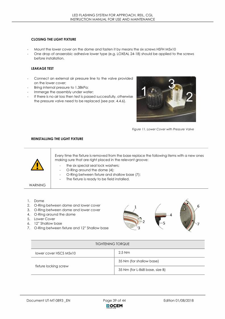
LEAKAGE TEST
- Connect an external air pressure line to the valve provided
on the lower cover;
- Bring internal pressure to 1.38kPa;
- Immerge the assembly under water;
- If there is no air loss then test is passed successfully, otherwise
the pressure valve need to be replaced (see par. 4.4.6).
Figure 11. Lower Cover with Pressure Valve
REINSTALLING THE LIGHT FIXTURE
1. Dome
2. O-Ring between dome and lower cover
3. O-Ring between dome and lower cover
4. O-Ring around the dome
5. Lower Cover
6. 12” Shallow base
7. O-Ring between fixture and 12” Shallow base
TIGHTENING TORQUE
lower cover HSCS M5x10 2.5 Nm
fixture locking screw
35 Nm (for shallow base)
35 Nm (for L-868 base, size B)
Every time the fixture is removed from the base replace the following items with a new ones
making sure that are right placed in the relevant groove:
- the six special seal lock washers;
- O-Ring around the dome (4);
- O-Ring between fixture and shallow base (7);
- The fixture is ready to be field installed.
WARNING

LED FLASHING SYSTEM FOR APPROACH, REIL, CGL
INSTRUCTION MANUAL FOR USE AND MAINTENANCE
Document UT-MT-0893 _EN Page 40 of 44 Edition 01/08/2018
4.4.3 Prism Cleaning and replacement
CLEANING
Outside Cleaning:
- Clean the prisms surface with non-abrasive glass product (NO paint thinner). Removing or opening
the fixture is not necessary.
Inside Cleaning:
NOTE: Prisms inside cleaning usually is not necessary because fixture is watertight.
- Remove the fixture from the base and open it (par 4.4.2)
- clean the prisms surfaces (Errore. L'origine riferimento non è
stata trovata. - n°1) with non-abrasive glass product (NO
paint thinner)
- dry them carefully
- Reassembly the light unit following instructions of par. 4.4.2
REPLACEMENT
Remove the fixture from the base and open it par. 4.4.2.
- Clean out possible pieces of the old prism
and all accumulated debris from the inside;
- Unscrew the two screws HSCS M5x12 (6) and
remove the mounting plate (5);
- Remove the old prism and the gasket;
carefully clean the prism seat by scraping
and taking care not to damage the relevant
walls;
- Place a new gasket (2) in the prism cavity on
the dome;
- Position and press by hand the prism (3) in the
relevant seat and place a new gasket in the
backside of the prism (4);
- Fasten the mounting plate (5) with the two
relevant screws HSCS M5x12 (6); tightening
torque is 2.5 Nm.
Figure 12. Prism replacement components
In case the prism is damaged, it must be replaced. It is highly recommended to do a
complete overhaul of the fixture. Contact OCEM - ENERGY TECHNOLOGY for any
suggestion.
WARNING

LED FLASHING SYSTEM FOR APPROACH, REIL, CGL
INSTRUCTION MANUAL FOR USE AND MAINTENANCE
Document UT-MT-0893 _EN Page 41 of 44 Edition 01/08/2018
4.4.4 LED module replacement
Remove the fixture from the base and open it following instructions of par. 4.4.2 and proceed as
follow:
- disconnect the power supply connector from the LED
module (4);
- remove the LED module (3) and the relevant reflector (1)
from the mounting plate unscrewing the two screw HSCS
M3x12;
- replace the LED module it with a new one;
- place the thermal interface (5) under the LED module
and right-positioned;
- place the Kapton insulating sheet (2) over the LED board
in the right position;
- fasten the LED module and the relevant reflector with a
tightening torque of 0.6 Nm;
- reconnect the power supply connector (4) to the LED
module.
Reassembly the fixture following instructions of par. 4.4.2.
Figure 13. LED Module Replacement components
4.4.5 Cable lead with plug replacement
Remove the fixture from the base and open it following instructions of par. 4.4.2.
- Inside the lower cover, disconnect the pair of wires from the electronics and cut the female faston
terminal;
- Unscrew the gland and pull out the cable lead with gland gasket;
- Insert on the new power supply cable lead with plug (1), the new gland nut (2) so that the available
length of cables outside the fixture is 0.46 m when re-assembled;
- Pull both cables through the suitable hole provided in the bottom of the lower cover;
- Cut the new cable sheath for the remaining length; - Splice each cable for a length of approx. 7 mm;
- Clamp the female faston terminal to the cable (3);
- Tighten the gland nut at 6Nm torque;
- Restore internally the electrical connections.
Close the light fixture following instructions of par. 4.4.2.

LED FLASHING SYSTEM FOR APPROACH, REIL, CGL
INSTRUCTION MANUAL FOR USE AND MAINTENANCE
Document UT-MT-0893 _EN Page 42 of 44 Edition 01/08/2018
4.4.6 Pressure valve replacement
In case the pressure valve needs replacing, operate as follows:
- Unscrew the valve body with gasket from the outside of the lower cover by clamping the
hexagonal end section of the valve body.
- Screw the new valve on the lower cover; tightening torque is 0.35 Nm.
Reassembly the light unit following instructions of par. 4.4.2.
4.4.7 LIFL Troubleshooting
PROBLEM POSSIBLE CAUSE SOLUTION
Distorted light beam
output
Broken or damaged prism Replace prism
Wrong prism installed CHECK PARTS LIST AND INSTALL THE
CORRECT PRISM
Weak light output
Dirty prism or dome Clean the light fixture
One LED of the luminous
source damaged in short
circuit (only without the
monitoring option)
Replace the LEDs board
Wrong electronic interface Check parts list and install the correct
electronic
Luminous source not
working
LEDS DEFECTIVE Replace the LEDs board
Moisture inside the fixture
Execute leakage test and replace
damaged components. Clean and
dry the inside area of the fixture
Water or moisture inside
the fixture
Prism gasket, O-rings
between dome and lower
cover
Replace all gasket and execute
leakage test
Pinched fixture power
cables Replace fixture leads
In case of leakage between the valve and the lower cover, check the tightening of the
valve body to the lower cover from the outside of the fixture.
WARNING

LED FLASHING SYSTEM FOR APPROACH, REIL, CGL
INSTRUCTION MANUAL FOR USE AND MAINTENANCE
Document UT-MT-0893 _EN Page 43 of 44 Edition 01/08/2018
5 SPARE PARTS
GROUP CODE DESCRIPTION
Flash Master Control
Unit (FMCU)
RISLF0002 Master Board (F316)
RISLF0003 Fuses kit
RISLF0004 Input Filter Board (F340)
RISLF0005 Touch Pad
RISLF0006 Auxiliary power supply
RISLF0007 Circuit breaker Q1
RISLF0008 Circuit breaker Q2
Flash Field Unit (FFU) RISLF0001 Flash Field Unit cabinet
LIFL
RISLF0009 Assembled dome
RISLF0010 Gasket Kit
RISLF0011 Prisms assembly
RISLF0012 Led module kit (F312)
RISLF0013 Electronic board Kit (F311)
RISLF0014 Kit power supply cable with plug
LEFL
RISLF0015 Led module Kit (F313)
RISLF0016 Electronic board Kit (F311)
RISLF0017 Transparent front protection
RISLF0018 Gasket Kit
LED FLASHING SYSTEM FOR APPROACH, REIL, CGL
INSTRUCTION MANUAL FOR USE AND MAINTENANCE
Document UT-MT-0893 _EN Page 44 of 44 Edition 01/08/2018
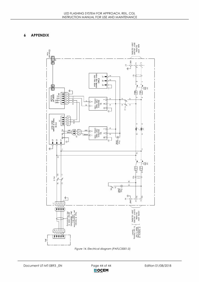
6 APPENDIX
Figure 14. Electrical diagram (PAFLC0001.0)