LED Driver Linear dimming Driver LC 50W 250–400mA 140V o4a ...
8
www.tridonic.com 1 Subject to change without notice. Information provided without guarantee. Data sheet 09/21-LC626-5 LED Driver Linear dimming Product description • Dimmable built-in constant current LED Driver • Dimming range 10 – 100 % (min. 25 mA) • For luminaires of protection class I and protection class II • Temperature protection as per EN 61347-2-13 C5e • Adjustable output current between 250 and 400 mA via I-SELECT 2 plugs • Max. output power 50 W • Up to 91 % efficiency • Power input on stand-by < 0.4 W • Nominal lifetime up to 100,000 h • 5 years guarantee (conditions at www.tridonic.com) Housing properties • Low profile metal casing with white cover • Type of protection IP20 Interfaces • one4all (DALI-2 DT 6, DSI, switchDIM, corridorFUNCTION V2) • Terminal blocks: 0° push terminals Functions • Adjustable output current in 1-mA-steps (I-SELECT 2) • Protective features (overtemperature, short-circuit, overload, no-load, input voltage range) • Suitable for emergency lighting acc. to EN 50172 Benefits • Application-oriented operating window for maximum compatibility Typical applications • For linear/area lighting È Standards, page 4 Driver LC 50W 250–400mA 140V o4a lp ADV advanced DALI non-SELV series
Transcript of LED Driver Linear dimming Driver LC 50W 250–400mA 140V o4a ...
www.tridonic.com 1Subject to change without notice. Information provided without guarantee.
Data sheet 09/21-LC626-5
LED Driver
Linear dimming
Product description
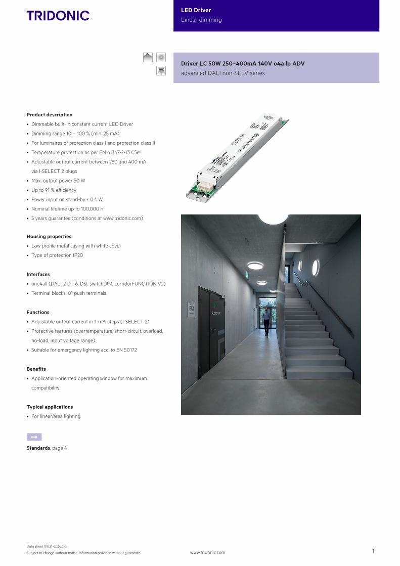
• Dimmable built-in constant current LED Driver
• Dimming range 10 – 100 % (min. 25 mA)
• For luminaires of protection class I and protection class II
• Temperature protection as per EN 61347-2-13 C5e
• Adjustable output current between 250 and 400 mA
via I-SELECT 2 plugs
• Max. output power 50 W
• Up to 91 % efficiency
• Power input on stand-by < 0.4 W
• Nominal lifetime up to 100,000 h
• 5 years guarantee (conditions at www.tridonic.com)
Housing properties
• Low profile metal casing with white cover
• Type of protection IP20
Interfaces
• one4all (DALI-2 DT 6, DSI, switchDIM, corridorFUNCTION V2)
• Terminal blocks: 0° push terminals
Functions
• Adjustable output current in 1-mA-steps (I-SELECT 2)
• Protective features (overtemperature, short-circuit, overload,
no-load, input voltage range)
• Suitable for emergency lighting acc. to EN 50172
Benefits
• Application-oriented operating window for maximum
compatibility
Typical applications
• For linear/area lighting
ÈStandards, page 4
Driver LC 50W 250–400mA 140V o4a lp ADV
advanced DALI non-SELV series
www.tridonic.com 2Subject to change without notice. Information provided without guarantee.
Data sheet 09/21-LC626-5
LED Driver
Linear dimming
Specific technical dataType Output
current5Min. forward
voltageMax. forward
voltageMax. output
powerTyp. power consumption
(at 230 V, 50 Hz, full load)Typ. current consumption (at 230 V, 50 Hz, full load)
Max. casing temperature tc
Ambient temperature ta max.
I-SELECT 2
resistor value4
LC 50/250-400/140 o4a lp ADV
250 mA 50 V 140 V 35.0 W 38.0 W 168 mA 70 °C -25 ... +50 °C open
275 mA 50 V 140 V 38.5 W 40.0 W 185 mA 70 °C -25 ... +50 °C 18.18 kΩ
300 mA 50 V 140 V 42.0 W 46.0 W 203 mA 70 °C -25 ... +50 °C 16.67 kΩ
325 mA 50 V 140 V 45.5 W 50.0 W 220 mA 70 °C -25 ... +50 °C 15.38 kΩ
350 mA 50 V 140 V 49.0 W 54.0 W 235 mA 70 °C -25 ... +50 °C 14.29 kΩ
375 mA 50 V 133 V 50.0 W 55.0 W 240 mA 75 °C -25 ... +50 °C 13.33 kΩ
400 mA 50 V 125 V 50.0 W 55.0 W 240 mA 75 °C -25 ... +50 °C short circuit (0 Ω)
1 Valid at 100 % dimming level.
2 Depending on the selected output current.
3 Depending on the DALI traffic at the interface.
4 Not compatible with I-SELECT (generation 1). Calculated resistor value.
5 Output current is mean value.
6 Valid for immediate change of power supply type otherwise the starting time is valid.
EL
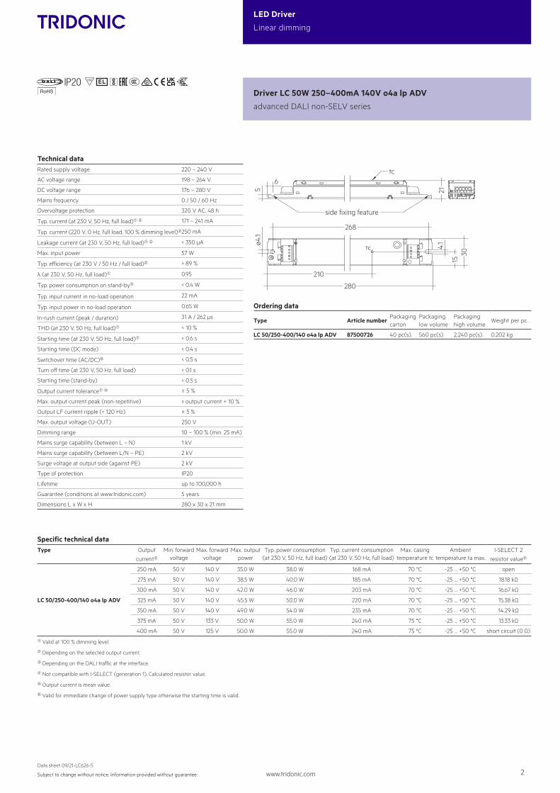
Technical dataRated supply voltage 220 – 240 V
AC voltage range 198 – 264 V
DC voltage range 176 – 280 V
Mains frequency 0 / 50 / 60 Hz
Overvoltage protection 320 V AC, 48 h
Typ. current (at 230 V, 50 Hz, full load)1 2 171 – 241 mA
Typ. current (220 V, 0 Hz, full load, 100 % dimming level)2250 mA
Leakage current (at 230 V, 50 Hz, full load)1 2 < 350 µA
Max. input power 57 W
Typ. efficiency (at 230 V / 50 Hz / full load)2 > 89 %
λ (at 230 V, 50 Hz, full load)1 0.95
Typ. power consumption on stand-by3 < 0.4 W
Typ. input current in no-load operation 22 mA
Typ. input power in no-load operation 0.65 W
In-rush current (peak / duration) 31 A / 262 µs
THD (at 230 V, 50 Hz, full load)1 < 10 %
Starting time (at 230 V, 50 Hz, full load)1 < 0.6 s
Starting time (DC mode) < 0.4 s
Switchover time (AC/DC)6 < 0.5 s
Turn off time (at 230 V, 50 Hz, full load) < 0.1 s
Starting time (stand-by) < 0.5 s
Output current tolerance1 5 ± 5 %
Max. output current peak (non-repetitive) ≤ output current + 10 %
Output LF current ripple (< 120 Hz) ± 5 %
Max. output voltage (U-OUT) 250 V
Dimming range 10 – 100 % (min. 25 mA)
Mains surge capability (between L – N) 1 kV
Mains surge capability (between L/N – PE) 2 kV
Surge voltage at output side (against PE) 2 kV
Type of protection IP20
Lifetime up to 100,000 h
Guarantee (conditions at www.tridonic.com) 5 years
Dimensions L x W x H 280 x 30 x 21 mm
Driver LC 50W 250–400mA 140V o4a lp ADV
advanced DALI non-SELV series
15
210
280
4.1
30
268
ø4.1
6
5 21
side fixing feature
tc
tc
Ordering data
Type Article numberPackaging carton
Packaging low volume
Packaging high volume
Weight per pc.
LC 50/250-400/140 o4a lp ADV 87500726 40 pc(s). 560 pc(s). 2,240 pc(s). 0.202 kg
I-SELECT 2 PLUG PRE / EXC
ACC
ES-
SOR
IES
3,5
xxxx
xxxx
5,5 4,5
7,513
,5
9
Ordering data
TypeArticle number
Colour Marking CurrentResistor value
Packaging bag
Weight per pc.
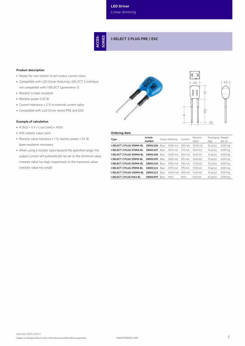
I-SELECT 2 PLUG 250MA BL 28001106 Blue 0250 mA 250 mA 20.00 kΩ 10 pc(s). 0.001 kg
I-SELECT 2 PLUG 275MA BL 28001107 Blue 0275 mA 275 mA 18.20 kΩ 10 pc(s). 0.001 kg
I-SELECT 2 PLUG 300MA BL 28001108 Blue 0300 mA 300 mA 16.50 kΩ 10 pc(s). 0.001 kg
I-SELECT 2 PLUG 325MA BL 28001109 Blue 0325 mA 325 mA 15.40 kΩ 10 pc(s). 0.001 kg
I-SELECT 2 PLUG 350MA BL 28001110 Blue 0350 mA 350 mA 14.30 kΩ 10 pc(s). 0.001 kg
I-SELECT 2 PLUG 375MA BL 28001111 Blue 0375 mA 375 mA 13.30 kΩ 10 pc(s). 0.001 kg
I-SELECT 2 PLUG 400MA BL 28001112 Blue 0400 mA 400 mA 12.40 kΩ 10 pc(s). 0.001 kg
I-SELECT 2 PLUG MAX BL 28001099 Blue MAX MAX 0.00 kΩ 10 pc(s). 0.001 kg
www.tridonic.com 3Subject to change without notice. Information provided without guarantee.
Data sheet 09/21-LC626-5
LED Driver
Linear dimming
I-SELECT 2 PLUG PRE / EXC
ACC
ES-
SOR
IES
3,5
xxxx
xxxx
5,5 4,5
7,513
,5
9
Ordering data
TypeArticle number
Colour Marking CurrentResistor value
Packaging bag
Weight per pc.
I-SELECT 2 PLUG 250MA BL 28001106 Blue 0250 mA 250 mA 20.00 kΩ 10 pc(s). 0.001 kg
I-SELECT 2 PLUG 275MA BL 28001107 Blue 0275 mA 275 mA 18.20 kΩ 10 pc(s). 0.001 kg
I-SELECT 2 PLUG 300MA BL 28001108 Blue 0300 mA 300 mA 16.50 kΩ 10 pc(s). 0.001 kg
I-SELECT 2 PLUG 325MA BL 28001109 Blue 0325 mA 325 mA 15.40 kΩ 10 pc(s). 0.001 kg
I-SELECT 2 PLUG 350MA BL 28001110 Blue 0350 mA 350 mA 14.30 kΩ 10 pc(s). 0.001 kg
I-SELECT 2 PLUG 375MA BL 28001111 Blue 0375 mA 375 mA 13.30 kΩ 10 pc(s). 0.001 kg
I-SELECT 2 PLUG 400MA BL 28001112 Blue 0400 mA 400 mA 12.40 kΩ 10 pc(s). 0.001 kg
I-SELECT 2 PLUG MAX BL 28001099 Blue MAX MAX 0.00 kΩ 10 pc(s). 0.001 kg
Product description
• Ready-for-use resistor to set output current value
• Compatible with LED Driver featuring I-SELECT 2 interface;
not compatible with I-SELECT (generation 1)
• Resistor is base insulated
• Resistor power 0.25 W
• Current tolerance ± 2 % to nominal current value
• Compatible with LED Driver series PRE and EXC
Example of calculation
• R [kΩ] = 5 V / I_out [mA] x 1000
• E96 resistor value used
• Resistor value tolerance ≤ 1 %; resistor power ≥ 0.1 W;
base insulation necessary
• When using a resistor value beyond the specified range, the
output current will automatically be set to the minimum value
(resistor value too big), respectively to the maximum value
(resistor value too small)
www.tridonic.com 4Subject to change without notice. Information provided without guarantee.
Data sheet 09/21-LC626-5
LED Driver
Linear dimming
1. Standards
EN 55015EN 61000-3-2EN 61000-3-3EN 61347-1 EN 61347-2-13 EN 62384EN 61547EN 62386-101 (DALI-2)EN 62386-102 (DALI-2)EN 62386-207 (DALI-2)According to EN 50172 for use in central battery systemsAccording to EN 60598-2-22 suitable for emergency lighting installations
2. Thermal details and lifetime
2.1 Expected lifetime
The LED Driver is designed for a lifetime stated above under reference conditions and with a failure probability of less than 10 %.
The relation of tc to ta temperature depends also on the luminaire design. If the measured tc temperature is approx. 5 K below tc max., ta temperature should be checked and eventually critical components (e.g. ELCAP) measured. Detailed information on request.
3. Installation / wiring
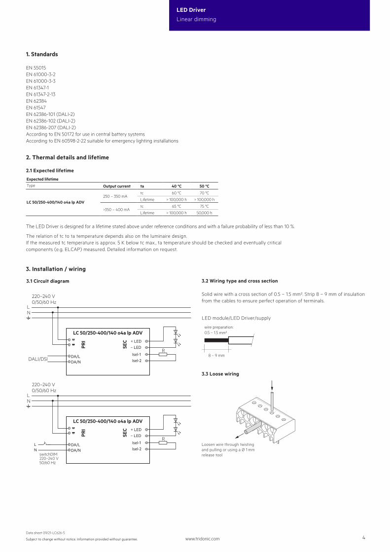
3.1 Circuit diagram
LC 50/250-400/140 o4a lp ADV
SEC
PRI
220–240 V
LN
0/50/60 Hz
+ LED– LED
Isel-1Isel-2
R
~~
DA/LDALI/DSIDA/N
LC 50/250-400/140 o4a lp ADV
SEC
PRI + LED
– LED
Isel-1Isel-2
R~~
220–240 V
LN
0/50/60 Hz
DA/LDA/N
switchDIM220–240 V50/60 Hz
LN
LED module/LED Driver/supply
8 – 9 mm
wire preparation:0.5 – 1.5 mm²
3.2 Wiring type and cross section
Solid wire with a cross section of 0.5 – 1.5 mm². Strip 8 – 9 mm of insulationfrom the cables to ensure perfect operation of terminals.
3.3 Loose wiring
Loosen wire through twisting and pulling or using a Ø 1 mm release tool
Expected lifetimeType Output current ta 40 °C 50 °C
LC 50/250-400/140 o4a lp ADV250 – 350 mA
tc 60 °C 70 °C
Lifetime > 100,000 h > 100,000 h
>350 – 400 mAtc 65 °C 75 °C
Lifetime > 100,000 h 50,000 h
www.tridonic.com 5Subject to change without notice. Information provided without guarantee.
Data sheet 09/21-LC626-5
LED Driver
Linear dimming
3.4 Wiring guidelines
• The cables should be run separately from the mains connections and mains cables to ensure good EMC conditions.
• The LED wiring should be kept as short as possible to ensure good EMC. The max. secondary cable length is 2 m (4 m circuit), this applies for LED output as well as for I-SELECT 2.• Secondary switching is not permitted.• The LED Driver has no inverse-polarity protection on the secondary side. Wrong polarity can damage LED modules with no inverse-polarity protection.• Wrong wiring of the LED Driver can lead to malfunction or irreparable damage.• To avoid the damage of the Driver, the wiring must be protected against short circuits to earth (sharp edged metal parts, metal cable clips, louver, etc.).
3.5 Hot plug-in
Hot plug-in is not supported due to residual output voltage of > 0 V. If a LED load is connected the device has to be restarted before the output will be activated again. This can be done via mains reset or via interface (DALI, DSI, switchDIM).
4. Electrical values
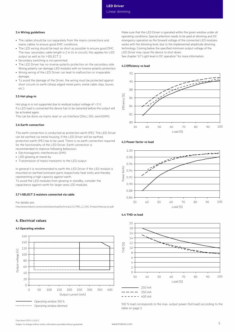
4.1 Operating window
80
84
86
82
88
90
30 50 7060 80 9040 100
92
Load [%]
Eic
ienc
y [%
]
4.2 Efficiency vs load
0,86
0,88
0,92
0,90
0,94
0,96
0,98
1,00
30 50 60 70 80 9040 100
Load [%]
Pow
er fa
ctor
4.3 Power factor vs load
0
20
30 80 9050 60 7040 100
8
6
4
2
12
10
14
16
18
Load [%]
TH
D [%
]
4.4 THD vs load
100 % load corresponds to the max. output power (full load) according to the table on page 2.
Operating window 100 %Operating window dimmed
250 mA
400 mA350 mA
0
20
40
60
100
80
200 250 300 350 40050 100 150
160
120
140
0
Output current [mA]
Out
put v
olta
ge [V
]
Make sure that the LED Driver is operated within the given window under all operating conditions. Special attention needs to be paid at dimming and DC emergency operation as the forward voltage of the connected LED modules varies with the dimming level, due to the implemented amplitude dimming technology. Coming below the specified minimum output voltage of the LED Driver may cause the device to shut-down. See chapter “6.7 Light level in DC operation” for more information.
3.7 I-SELECT 2 resistors connected via cable
For details see: http://www.tridonic.com/com/en/download/technical/LCA_PRE_LC_EXC_ProductManual_en.pdf.
3.6 Earth connection
The earth connection is conducted as protection earth (PE). The LED Driver can be earthed via metal housing. If the LED Driver will be earthed, protection earth (PE) has to be used. There is no earth connection required for the functionality of the LED Driver. Earth connection is recommended to improve following behaviour:• Electromagnetic interferences (EMI)• LED glowing at stand-by• Transmission of mains transients to the LED output
In general it is recommended to earth the LED Driver if the LED module is mounted on earthed luminaire parts respectively heat sinks and thereby representing a high capacity against earth.To avoid the LED modules from glowing in standby, consider the capacitance against earth for larger area LED modules.
www.tridonic.com 6Subject to change without notice. Information provided without guarantee.
Data sheet 09/21-LC626-5
LED Driver
Linear dimming
Automatic circuit breaker type C10 C13 C16 C20 B10 B13 B16 B20 Inrush current
Installation Ø 1.5 mm2 1.5 mm2 2.5 mm2 2.5 mm2 1.5 mm2 1.5 mm2 2.5 mm2 2.5 mm2 Imax
time
LC 50/250-400/140 o4a lp ADV 16 21 28 35 10 13 17 21 31 A 262 µs
4.7 Dimming
Dimming range 10 % to 100 %Digital control with:• DSI signal: 8 bit Manchester Code
Speed 10 % to 100 % in 1.4 s• DALI signal: 16 bit Manchester Code Speed 10 % to 100 % in 0.2 s Programmable parameter:
Minimum dimming level Maximum dimming level
Default minimum = 10 % Programmable range 10 % ≤ MIN ≤ 100 % Default maximum = 100 % Programmable range 100 % ≥ MAX ≥ 10 %
Dimming curve is adapted to the eye sensitiveness.Dimming is realized by amplitude dimming.
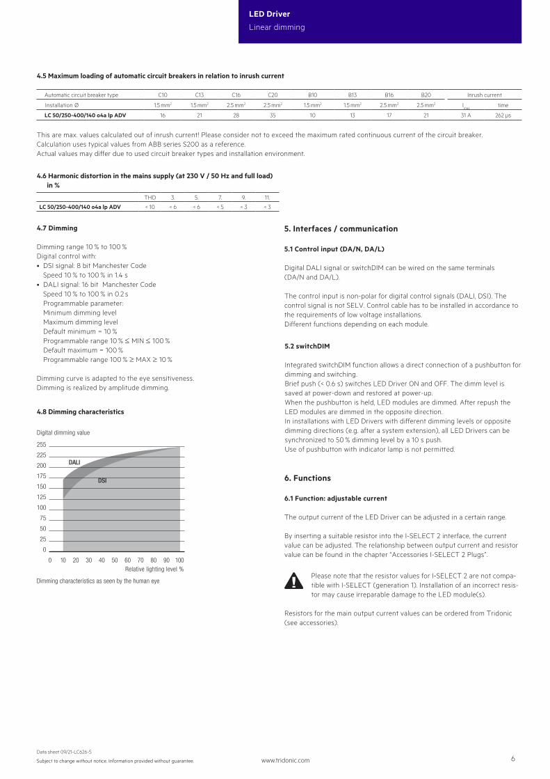
4.8 Dimming characteristics
4.6 Harmonic distortion in the mains supply (at 230 V / 50 Hz and full load) in %
THD 3. 5. 7. 9. 11.
LC 50/250-400/140 o4a lp ADV < 10 < 6 < 6 < 5 < 3 < 3
5.2 switchDIM
Integrated switchDIM function allows a direct connection of a pushbutton for dimming and switching.Brief push (< 0.6 s) switches LED Driver ON and OFF. The dimm level is saved at power-down and restored at power-up.When the pushbutton is held, LED modules are dimmed. After repush the LED modules are dimmed in the opposite direction.In installations with LED Drivers with different dimming levels or opposite dimming directions (e.g. after a system extension), all LED Drivers can be synchronized to 50 % dimming level by a 10 s push.Use of pushbutton with indicator lamp is not permitted.
6. Functions
5. Interfaces / communication
5.1 Control input (DA/N, DA/L)
Digital DALI signal or switchDIM can be wired on the same terminals (DA/N and DA/L).
The control input is non-polar for digital control signals (DALI, DSI). The control signal is not SELV. Control cable has to be installed in accordance to the requirements of low voltage installations. Different functions depending on each module.
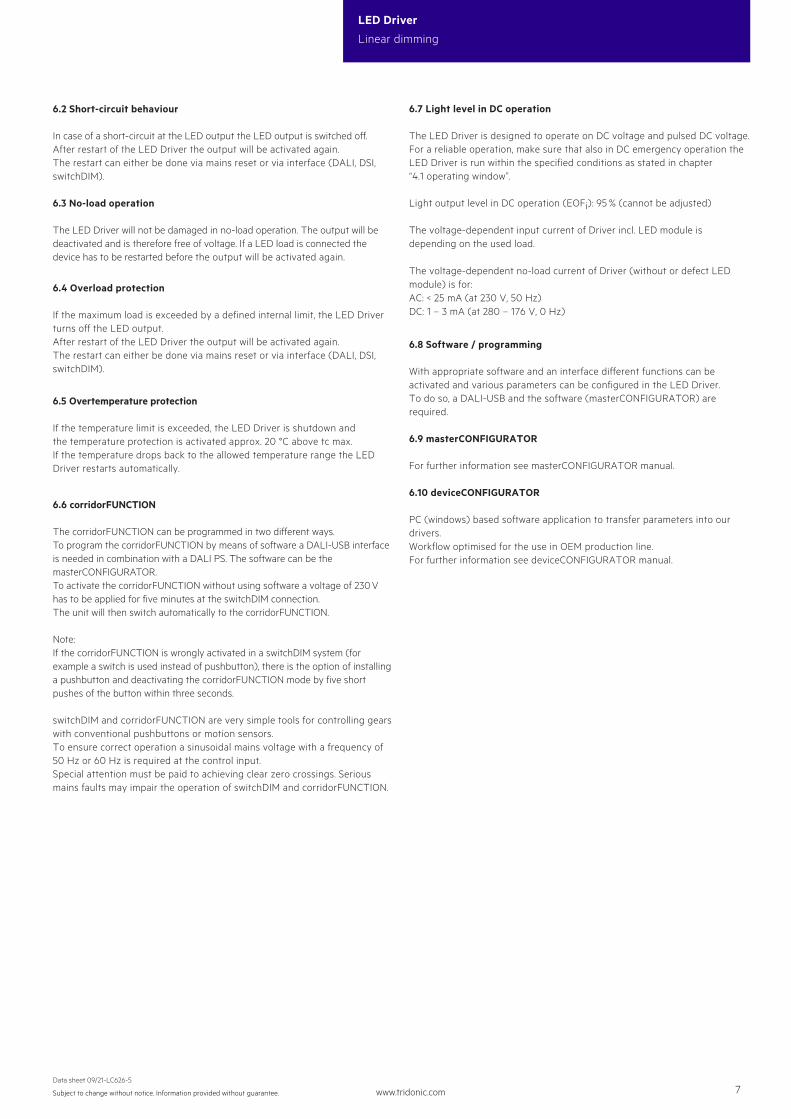
6.1 Function: adjustable current
The output current of the LED Driver can be adjusted in a certain range.
By inserting a suitable resistor into the I-SELECT 2 interface, the current value can be adjusted. The relationship between output current and resistor value can be found in the chapter “Accessories I-SELECT 2 Plugs”.
Please note that the resistor values for I-SELECT 2 are not compa-tible with I-SELECT (generation 1). Installation of an incorrect resis-tor may cause irreparable damage to the LED module(s).
Resistors for the main output current values can be ordered from Tridonic (see accessories).
225
255
DALI200
175
150
125
100
75
50
25
0
1009080706050403020100
Dimming characteristics
Digital dimming value
Relative lighting level %
DSI
Dimming characteristics as seen by the human eye
4.5 Maximum loading of automatic circuit breakers in relation to inrush current
This are max. values calculated out of inrush current! Please consider not to exceed the maximum rated continuous current of the circuit breaker. Calculation uses typical values from ABB series S200 as a reference.Actual values may differ due to used circuit breaker types and installation environment.
www.tridonic.com 7Subject to change without notice. Information provided without guarantee.
Data sheet 09/21-LC626-5
LED Driver
Linear dimming
6.2 Short-circuit behaviour
In case of a short-circuit at the LED output the LED output is switched off. After restart of the LED Driver the output will be activated again. The restart can either be done via mains reset or via interface (DALI, DSI, switchDIM).
6.3 No-load operation
The LED Driver will not be damaged in no-load operation. The output will be deactivated and is therefore free of voltage. If a LED load is connected the device has to be restarted before the output will be activated again.
6.4 Overload protection
If the maximum load is exceeded by a defined internal limit, the LED Driver turns off the LED output. After restart of the LED Driver the output will be activated again. The restart can either be done via mains reset or via interface (DALI, DSI, switchDIM).
6.5 Overtemperature protection
If the temperature limit is exceeded, the LED Driver is shutdown and the temperature protection is activated approx. 20 °C above tc max.If the temperature drops back to the allowed temperature range the LED Driver restarts automatically.
6.6 corridorFUNCTION
The corridorFUNCTION can be programmed in two different ways.To program the corridorFUNCTION by means of software a DALI-USB interface is needed in combination with a DALI PS. The software can be the masterCONFIGURATOR.To activate the corridorFUNCTION without using software a voltage of 230 V has to be applied for five minutes at the switchDIM connection. The unit will then switch automatically to the corridorFUNCTION.
Note:If the corridorFUNCTION is wrongly activated in a switchDIM system (for example a switch is used instead of pushbutton), there is the option of installing a pushbutton and deactivating the corridorFUNCTION mode by five short pushes of the button within three seconds.
switchDIM and corridorFUNCTION are very simple tools for controlling gears with conventional pushbuttons or motion sensors.To ensure correct operation a sinusoidal mains voltage with a frequency of 50 Hz or 60 Hz is required at the control input.Special attention must be paid to achieving clear zero crossings. Serious mains faults may impair the operation of switchDIM and corridorFUNCTION.
6.8 Software / programming
With appropriate software and an interface different functions can be activated and various parameters can be configured in the LED Driver. To do so, a DALI-USB and the software (masterCONFIGURATOR) are required.
6.9 masterCONFIGURATOR
For further information see masterCONFIGURATOR manual.
6.10 deviceCONFIGURATOR
PC (windows) based software application to transfer parameters into our drivers.Workflow optimised for the use in OEM production line.For further information see deviceCONFIGURATOR manual.
6.7 Light level in DC operation
The LED Driver is designed to operate on DC voltage and pulsed DC voltage. For a reliable operation, make sure that also in DC emergency operation the LED Driver is run within the specified conditions as stated in chapter “4.1 operating window”. Light output level in DC operation (EOFi): 95 % (cannot be adjusted)
The voltage-dependent input current of Driver incl. LED module is depending on the used load.
The voltage-dependent no-load current of Driver (without or defect LED module) is for:AC: < 25 mA (at 230 V, 50 Hz)DC: 1 – 3 mA (at 280 – 176 V, 0 Hz)
www.tridonic.com 8Subject to change without notice. Information provided without guarantee.
Data sheet 09/21-LC626-5
LED Driver
Linear dimming
7.2 Conditions of use and storage
Humidity: 5 % up to max. 85 %, not condensed (max. 56 days/year at 85 %)
Storage temperature: -40 °C up to max. +80 °C
The devices have to be acclimatised to the specified temperature range (ta) before they can be operated.
The LED Driver is declared as inbuilt LED controlgear, meaning it is intended to be used within a luminaire enclosure.If the product is used outside a luminaire, the installation must provide suitable protection for people and environment (e.g. in illuminated ceilings).
7.1 Insulation and electric strength testing of luminaires
Electronic devices can be damaged by high voltage. This has to be considered during the routine testing of the luminaires in production.
According to IEC 60598-1 Annex Q (informative only!) or ENEC 303-Annex A, each luminaire should be submitted to an insulation test with 500 V DC for 1 second. This test voltage should be connected between the interconnected phase and neutral terminals and the earth terminal. The insulation resistance must be at least 2 MΩ.
As an alternative, IEC 60598-1 Annex Q describes a test of the electrical strength with 1500 V AC (or 1.414 x 1500 V DC). To avoid damage to the electronic devices this test must not be conducted.
7.4 Additional information
Additional technical information at www.tridonic.com → Technical Data
Lifetime declarations are informative and represent no warranty claim.No warranty if device was opened.
7. Miscellaneous
7.3 Maximum number of switching cycles
All LED Driver are tested with 50,000 switching cycles.