Lectures The Power of Feedback - Automatic Control · acc um l tors Variable stroke ... Robert...
8
1 Ships and Aerospace Karl Johan Åström Department of Automatic Control LTH Lund University Ships and Aerospace K. J. Åström 1. Introduction 2. Ships 3. Early Autopilots for Aircrafts 4. German Autopilots 5. Missiles 6. Later Developments 7. Summary Theme: Gyroscopes, powerful actuators and mission critical systems. Lectures 1940 1960 2000 1 Introduction 2 Governors | | | 3 Process Control | | | 4 Feedback Amplifiers | | | 5 Harry Nyquist | | | 6 Aerospace | | | | 7 Servomechanisms ← | | 8 The Second Phase ← ← | 9 The Third Phase ← ← ← 10 The Swedish Scene 11 The Lund Scene The Power of Feedback Feedback has some amazing properties, it can ◮ make a system insensitive to disturbances, ◮ make good systems from bad components, ◮ follow command signals, ◮ stabilize an unstable system, ◮ create desired behavior, for example linear behavior from nonlinear components. The major drawbacks are that ◮ feedback can cause instabilities ◮ sensor noise is fed into the system Introduction ◮ Driving forces: Emerging technologies such as expanded use of steam power, airplanes, space ships ◮ New components Actuators Flywheels, Steam servos, Hydraulic servos Sensors Gyroscopes, Pendulums, Accelerometers ◮ Control principles PID rediscovered ◮ New elements Integrated process and control design Mission critical applications Man-in-the-loop ◮ Parallels with governors up to 1910 ◮ Interesting continuation through 1940 and beyond Ships and Aerospace K. J. Åström 1. Introduction 2. Ships 3. Early Autopilots for Aircrafts 4. German Autopilots 5. Missiles 6. Later Developments 7. Summary Theme: Gyroscopes, powerful actuators and mission critical systems. Ships ◮ Era of large steam ships 1835 Great Western Railway Company 1837 Great Western Bristol-New York 1845 Great Britain 1859 Great Eastern ◮ Engine control overlap with governors Open loop Augusta 1855 Closed loop steam servo Great Eastern ◮ Steering ◮ Servo motor (Servomoteur) ◮ Roll stabilization ◮ Gun-turrets ◮ Torpedos ◮ Submarines Hydraulic Steering Engines ◮ Drawback of steam ◮ Servo-moteur 1868 Jean Joseph Farcot ◮ 1870 A. B. Brown patent on hydraulic servomechanism ◮ Farcot: Le servo-moteur ou moteur asservi (1873) ◮ Multi-stage systems ◮ A helmsman exerts 30-40 N to operate the rudder which requires loads as high as 10 5 N. ◮ Could operate large 800 kW engines ◮ Constant pressure fixed displacement pumps and accumulators ◮ Variable stroke pumps 1911 ◮ Hele-Shaw and Martineau: Measurement of dynamic input output characteristics
Transcript of Lectures The Power of Feedback - Automatic Control · acc um l tors Variable stroke ... Robert...
1
Ships and Aerospa ce
Karl Johan Åström
Department of Automatic Control LTHLund University
Ships and Aerospa ce
K. J. Åström
1. Introduction
2. Ships
3. Early Autopilots for Aircrafts
4. German Autopilots
5. Missiles
6. Later Developments
7. Summary
Theme: Gyroscopes, powerful actuators and mission criticalsystems.
Lectures
1940 1960 20001 Introduction2 Governors | | |3 Process Control | | |4 Feedback Amplifiers | | |5 Harry Nyquist | | |6 Aerospace | | |
|7 Servomechanisms ← | |8 The Second Phase ← ← |9 The Third Phase ← ← ←
10 The Swedish Scene11 The Lund Scene
The Power of Feedback
Feedback has some amazing properties, it can
◮ make a system insensitive to disturbances,◮ make good systems from bad components,◮ follow command signals,◮ stabilize an unstable system,◮ create desired behavior, for example linear behavior from
nonlinear components.
The major drawbacks are that
◮ feedback can cause instabilities◮ sensor noise is fed into the system
Int roduc tion
◮ Driving forces: Emerging technologies such as expandeduse of steam power, airplanes, space ships
◮ New componentsActuators
Flywheels, Steam servos, Hydraulic servosSensors
Gyroscopes, Pendulums, Accelerometers
◮ Control principlesPID rediscovered
◮ New elementsIntegrated process and control designMission critical applicationsMan-in-the-loop
◮ Parallels with governors up to 1910◮ Interesting continuation through 1940 and beyond
Ships and Aerospa ce
K. J. Åström
1. Introduction
2. Ships
3. Early Autopilots for Aircrafts
4. German Autopilots
5. Missiles
6. Later Developments
7. Summary
Theme: Gyroscopes, powerful actuators and mission criticalsystems.
Ships
◮ Era of large steam ships1835 Great Western Railway Company1837 Great Western Bristol-New York1845 Great Britain1859 Great Eastern
◮ Engine control overlap with governorsOpen loop Augusta 1855Closed loop steam servo Great Eastern
◮ Steering◮ Servo motor (Servomoteur)◮ Roll stabilization◮ Gun-turrets◮ Torpedos◮ Submarines
Hydraul ic Steering Engi nes
◮ Drawback of steam◮ Servo-moteur 1868 Jean Joseph Farcot◮ 1870 A. B. Brown patent on hydraulic servomechanism◮ Farcot: Le servo-moteur ou moteur asservi (1873)◮ Multi-stage systems◮ A helmsman exerts 30-40 N to operate the rudder which
requires loads as high as 105 N.◮ Could operate large 800 kW engines◮ Constant pressure fixed displacement pumps and
accumulators◮ Variable stroke pumps 1911◮ Hele-Shaw and Martineau: Measurement of dynamic input
output characteristics

2
Farcos 2 Stage Servo
Feedback in the actuator
|
Torpedos
◮ Most advanced control systems in the late 1800◮ Robert Whitehead showed a torpedo driven by pneumatic
engine at Fiume for Austrian Navy in 1869◮ Great interest from England◮ Whitehead torpedos built for the Admiralty◮ Depth control
The secret - proportional feedback from depth and attitude
◮ In the US the Howell torpedo driven by heavy flywheel(10000 rpm). Depth control by mechanical servo poweredfrom flywheel. Flywheel acted as a gyro, roll tendencycompensated for by feedback.
◮ 1895 Ludwig Obry of the Austrian Navy invented agyroscope for use in torpedo.
Stabi lization and Steering of Ships
◮ Impact of gyrosGyro stabilization Schlick 1904Anschütz gyro compass 1906 (Max Schuler)Sperry gyrocompass 1911Sperry 1908 active stabilizer
◮ Automatic steering◮ Werner Siemens automatic steering of torpedo boats
1872-74. Rudder operated by electric motor, relays,connected to magnetic needle.
◮ Connect steering engine to gyrocompass◮ Brown failed with proportional control◮ Similar problems encountered with torpedoes◮ Problem was fixed by James B. Henderson in 1913 with
check helm (derivative action), implemented by a rate gyro
Elmer Sperry 1860-1930
◮ Cornell 1878-79◮ Several electric companies Sperry Electric Mining Machine
Company, 1888◮ Sperry Gyroscope Company 1910
Gyrocompass, autopilots, bomb-sights, flight control, IP◮ London office 1913
◮ Major supplier of gyro-compasses to Britain and Russia incompetition with Anschütz
◮ Sperry Rand (Remington Rand) 1955 Univac Computer◮ Unisys after merger with Burroughs 1986◮ Sperry Marine 1913 now part of Northrup Grumman
Sperry’s Gyropi lot - Metal Mike
◮ Sperry’s philosophy: "An experienced helmsman should‘meet’ the helm, that is, back off the helm and put it overthe other way to prevent the angular momentum of the shipcarrying it past the desired heading."
◮ Work started 1912◮ Compare with Fuzzy control◮ Patent on anticipator applied
1914, granted 1920◮ Trials April and October 1922◮ The metal-Mike behaved like an
experienced helmsman.◮ More than 400 systems installed
by 1932
Block Diagram of Metal Mike
◮ Notice actuation with an electric motor, with relay as anamplifier.
◮ Feedback makes the combination behave as a linearsystem.
◮ Nice example of how feedback can be used to shape linearbehavior from nonlinear components. See Billmanregulator later.
Metal Mike 2 The Autopi lot - From Sperry Manual
Controller parameters
◮ Rudder ratio (proportional gain kp = 1, 2, 3, 4)◮ Rate sensitivity (derivative gain kd = 0− 135)◮ Rate signal filtering (T f = 0, 5, 10, 15 factory chosen)◮ Rudder bias (integral gain ki ( 0.001◮ Weather adjust (dead zone max 3○)
Under practical seaway conditions, ships are always subject tosome yawing and this can create large rudder swings throughthe rate channel action. Such rudder swings may not contributeto course regulation of the ship since the ship’s response is notfast enough, and these useless rudder swings are classified as’rudder activity’. Rudder activity must be avoided since itinduces additional drag on the ship and wear of the steeringsystem. The solution is to filter the derivative. This filtering canbe very effective, but the filter constants must be prudentlychosen.
3
Nichol as Minor sky 1885 -
◮ Born 1885 in Karcheva◮ Imperial Technical School St. Petersburg (Vyshnegradski?)◮ Joined Russian Navy 1917◮ Emigrated USA 1918◮ Assistant to Steimetz at GE Research◮ Experiments with US Navy 1922 PID◮ Successful but never pursued◮ Competed with Sperry◮ Patents sold to Bendix 1930◮ Professor at Stanford
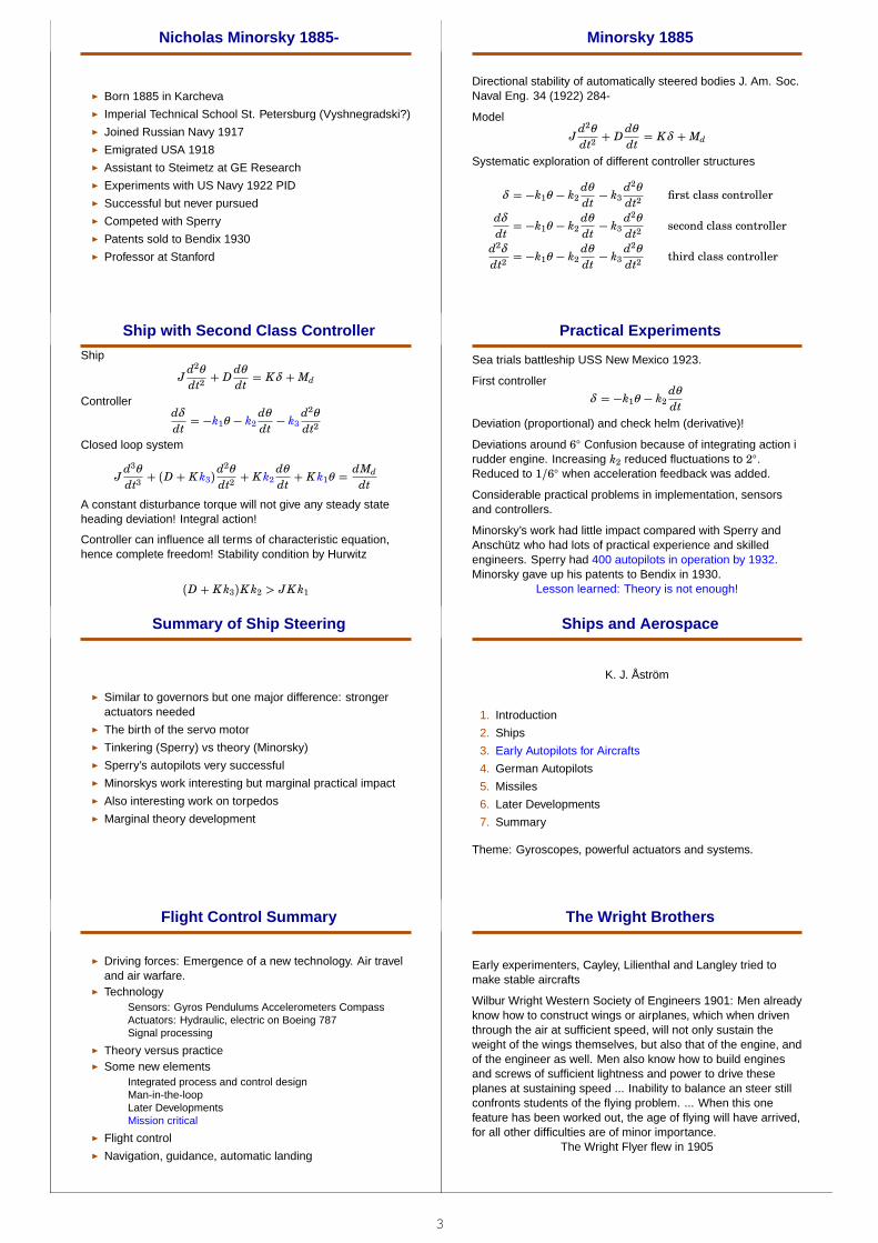
Minor sky 1885
Directional stability of automatically steered bodies J. Am. Soc.Naval Eng. 34 (1922) 284-
Model
Jd2θ
dt2+ D
dθ
dt= Kδ + Md
Systematic exploration of different controller structures
δ = −k1θ − k2dθ
dt− k3
d2θ
dt2first class controller
dδ
dt= −k1θ − k2
dθ
dt− k3
d2θ
dt2second class controller
d2δ
dt2= −k1θ − k2
dθ
dt− k3
d2θ
dt2third class controller
Ship with Second Class Cont rol ler
Ship
Jd2θ
dt2+ D
dθ
dt= Kδ + Md
Controllerdδ
dt= −k1θ − k2
dθ
dt− k3
d2θ
dt2
Closed loop system
Jd3θ
dt3+ (D + Kk3)
d2θ
dt2+ Kk2
dθ
dt+ Kk1θ =
dMd
dt
A constant disturbance torque will not give any steady stateheading deviation! Integral action!
Controller can influence all terms of characteristic equation,hence complete freedom! Stability condition by Hurwitz
(D + Kk3)Kk2 > JKk1
Practical Experiments
Sea trials battleship USS New Mexico 1923.
First controller
δ = −k1θ − k2dθ
dt
Deviation (proportional) and check helm (derivative)!
Deviations around 6○ Confusion because of integrating action irudder engine. Increasing k2 reduced fluctuations to 2○.Reduced to 1/6○ when acceleration feedback was added.
Considerable practical problems in implementation, sensorsand controllers.
Minorsky’s work had little impact compared with Sperry andAnschütz who had lots of practical experience and skilledengineers. Sperry had 400 autopilots in operation by 1932.Minorsky gave up his patents to Bendix in 1930.
Lesson learned: Theory is not enough!
Summary of Ship Steering
◮ Similar to governors but one major difference: strongeractuators needed
◮ The birth of the servo motor◮ Tinkering (Sperry) vs theory (Minorsky)◮ Sperry’s autopilots very successful◮ Minorskys work interesting but marginal practical impact◮ Also interesting work on torpedos◮ Marginal theory development
Ships and Aerospa ce
K. J. Åström
1. Introduction
2. Ships
3. Early Autopilots for Aircrafts
4. German Autopilots
5. Missiles
6. Later Developments
7. Summary
Theme: Gyroscopes, powerful actuators and systems.
Flight Cont rol Summary
◮ Driving forces: Emergence of a new technology. Air traveland air warfare.
◮ TechnologySensors: Gyros Pendulums Accelerometers CompassActuators: Hydraulic, electric on Boeing 787Signal processing
◮ Theory versus practice◮ Some new elements
Integrated process and control designMan-in-the-loopLater DevelopmentsMission critical
◮ Flight control◮ Navigation, guidance, automatic landing
The Wright Brothers
Early experimenters, Cayley, Lilienthal and Langley tried tomake stable aircrafts
Wilbur Wright Western Society of Engineers 1901: Men alreadyknow how to construct wings or airplanes, which when driventhrough the air at sufficient speed, will not only sustain theweight of the wings themselves, but also that of the engine, andof the engineer as well. Men also know how to build enginesand screws of sufficient lightness and power to drive theseplanes at sustaining speed ... Inability to balance an steer stillconfronts students of the flying problem. ... When this onefeature has been worked out, the age of flying will have arrived,for all other difficulties are of minor importance.
The Wright Flyer flew in 1905

4
Draper on Wright
Draper Head of Department of Aeronautical Engineering andfounding Director of the Instrumentation Laboratory at MIT
The 43rd Wilbur Wright Memorial Lecture before the RoyalAeronautical Society, May 19 1955.
The Wright Brothers rejected the principle that aircraft shouldbe made inherently so stable that the human pilot would onlyhave to steer the vehicle, playing no part in stabilization.Instead they deliberately made their airplane with negativestability and depended on the human pilot to operate themovable surface controls so that the flying system - pilot andmachine - would be stable. This resulted in and increase inmanoeuvrability and controllability.
Sperry Autopi lot 1914
Air Club of France: Le Concours de la Securité en Aeroplane.
Curtis Flying Boat
Sperry Autopi lot 1914
◮ Directional and horizontal gyros◮ Propeller driven air-turbine◮ Solenoid clutches
The Role of Theory
◮ The Royal Aircraft Establishment RAE in Great Britain◮ Strong applied mathematics tradition◮ Routh’s stability conditions known and used◮ Melvill Jones: "In spite .. of the completeness of the
experimental an theoretical structure ... it is undoubtedlytrue that, at the time of writing, calculations of this kind arevery little used by any but a few research workers. It is infact rare for anyone actually engaged upon the design ofaeroplanes to make direct use of computations ..., or evento be familiar with the methods by which they are made. ...In my own opinion it is the difficulty of computation ...which as prevented designers of aeroplanes from makinguse of the methods. ..."
Flight Dynamics
◮ G. H. Bryan Stability in Aviation, Mc Millan London. 1911.Linearization, separation of longitudinal and lateral, coined"stability derivative".
◮ 1911 Bairstow and Melvill Jones measured stabilityderivatives and calculated motions of practical airplanes.
◮ 1924 Gates, Garner and Cowley assumed that controlsmoved according to certain "control laws" and calculatedmotion of aircraft. Garner made provision for lag inapplication of control (actuator dynamics!).
◮ 1935 Melvill Jones: Dynamics of the Airplane, in W.Durand, editor Aerodynamic Theory, Durand ReprintingCommittee, Pasadena, CA. Practical experiments thatverified theory is applicable
Ships and Aerospa ce
K. J. Åström
1. Introduction
2. Ships
3. Early Autopilots for Aircrafts
4. German Autopilots
5. Missiles
6. Later Developments
7. Summary
Theme: Gyroscopes, powerful actuators and systems.
Flight Cont rol in Germany
Driving forces:
◮ The Versailles Peace Treaty of June 28, 1919 prohibitedGermany to have air force, tanks and heavy artillery.
◮ Development civil aviation, rockets and missiles◮ Requirements and specifications for flight-control systems
from Lufthansa who made regular flights to Moscow,London, Paris and Rome in the 1920s. Interest to keepschedules under all meteorological conditions. Instrumentssuch as turn indicators, magnetic compass, air speedindicators used. Desire to control direction automatically.
◮ Instrument flight tedious, one person keeps the course bylooking at the compass, the other holds speed and altitude.Instruments were important.
Major actors:
◮ Air Ministry, The Army Ordinance Department◮ Industry: Anschütz, Siemens, Askania, Möller-Patin
Winfried Oppelt 1912-1999
◮ Dipl. ing. Technische Physik, Technische HochschuleDarmstadt 1934
◮ Deutsche Versuchsanstalt für Luftfahrt Berlin 1934-37◮ Anschütz Kiel 1937-42◮ Siemens Luftfahrtgerätewerk Berlin 1942-45◮ PhD Darmstadt 1943◮ TH Braunschweig 1943-47, Hartmann und Braun 1947-57◮ Built a premier control department in Darmstadt◮ Lecturer in EE TH Darmstadt 1952-57◮ Professor TH Darmstadt 1957-77◮ Kleines Handbuch technischer Regelvorgänge, 1954.◮ A Historical Review of Autopilot Development, Research
and Theory in Germany. ASME J. Dynamics Systems,Measurement and Control 98:3(1976) 215-222.
5
Advances in Theory
W. Oppelt: "A general theory of flight control did not exist at thattime, it was unknown that all control problems followed thesame rules. In every application-filed an own control philosophyarose and led sometimes to very curious ideas. Since the basisfor an objective proof was not available, the different opinionswere presented with persistence according to the temperamentof the individual."
Works by Stodola and Tolle well known. Teaching by MaxSchuler, head of the Institute of Applied Mechanics in Göttingensince 1923. "Einführung in die Theorie der selbstättigenregeler." Leipzig 1956.
Karl Küpfmüller (1897-1977) Prof Darmstadt 1928. "Über dieDynamik der selbstättigen Verstärkungsregeler" ENT Vol 51928, circuit theory, stability, block diagrams. Stability from stepresponses with an interesting mathematical model.
Prof Adolf Leonhard Stuttgart 1936 (1899-1995)
Askania 1927
Experience in airplane instrumentation, altimeter, air-driventurn-indicator, magnetic compass with pneumatic pickoff,airspeed indicator. Also experience with jet-tube basedindustrial controllers.
◮ Askania◮ Sensors: Altimeter, turn indicator, magnetic compass,
air-speed indicator (all pneumatic)◮ Actuator: pneumatic jet tube◮ Test flights in 1927 airship Zeppelin LZ 127◮ Production unit tested on Junkers W32 and Ju 52◮ Disappointing results◮ Only mean value of magnetic compass could be used for
feedback, gyroscope was needed for good results◮ Great improvement with gyroscope licensed from Sperry
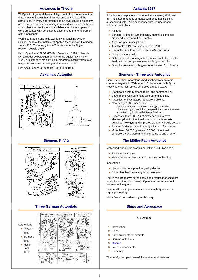
Askania’s Autopi lot Siemens - Three axis Autopi lot
Siemens Central-Laboratories had finished work on radiocontrol of target ship "Zähringen". Collaboration with Bykov.Received order for remote controlled airplane 1927.
◮ Stabilization with Siemens radio- and command-link.◮ Experiments with automatic take-off and landing.◮ Autopilot not satisfactory, hardware problems.◮ New design 1930 under Fishel.
Sensors: magnetic compass, rate gyro, later alsodirectional. gyro, pendulum, airspeed, barometric altimeter.Actuation: Hydraulic with internal feedback.
◮ Successful test 1932. Air Ministry decides to haveelectro-hydraulic directional control, not a three axisautopilot. New gyro and improved electro-hydraulic servos.
◮ Successful design used in nearly all types of airplanes.◮ More than 100 000 gyros and 35 000. directional
controllers K1Vü were manufactured up to end of WWII.
Siemens K IV ü The Möl ler-Patin Autopi lot
Möller had worked for Askania but left in 1934. Two goals:
◮ Pure electric control◮ Match the controllers dynamic behavior to the pilot
Innovations
◮ Use actuator as a pure integrating device◮ Added feedback from angular acceleration
Test in mid 1930 gave surprisingly good results that could notbe explained (complex zeros!). Operation was very smoothbecause of integrator.
Later additional improvements due to simplicity of electricsignal processing.
Mass Production ordered by Air Ministry.
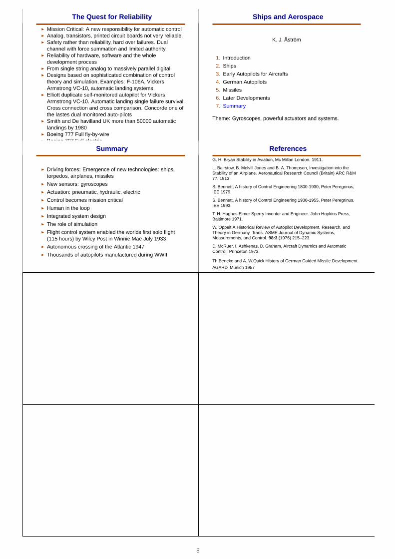
Three German Autopi lots
Left to right◮ Askania
1927–◮ Siemens
1927-◮ Möller-
Patin
1935
Ships and Aerospa ce
K. J. Åström
1. Introduction
2. Ships
3. Early Autopilots for Aircrafts
4. German Autopilots
5. Missiles
6. Later Developments
7. Summary
Theme: Gyroscopes, powerful actuators and systems.

6
Rockets and Miss iles
◮ Jules Verne◮ Meshcherskii late 1800◮ Tsiolkovskii late 1800◮ Goddard 1910-30◮ Oberth 1920◮ Werner van Braun V2 (A4)◮ Sputnik 1957◮ Apollo◮ JPL and unmanned space crafts Gemini
The German Guided Miss ile Progr am
A very extensive program
◮ Rocket technology◮ V-1◮ V-2◮ Radio guidance◮ TV guidance◮ IR guidance◮ Technology: Sensors, actuators, controls◮ Strong impact on future US and USSR programs
Col lection of German Guided Miss iles The V1 Cruise Miss ile
◮ Originally proposed by Air Ministry Technical Office atbeginning of war. Turned down by General Staff
◮ Project reestablished June 10, 1942◮ Development, testing, troop training and production very
fast 2 years and 3 days◮ Military operations began June 13, 1944 with 5000
systems◮ 8000 missiles launched against London, 2000 lost
immediately, about 2400 reached the target
The V1 Cruise Miss ile Repöv ning Gotska Sandön
V2 Balli stic Miss ile
◮ Work begun in 1929 because of restrictions on long-rangeartillery
◮ Create a mobile, effective weapon to strengthen a smallarmy
◮ Rocket development in Kummersdorf General Dornbergerand Werner von Braun started by Army OrdinanceDepartment
◮ First successful shot October 3, 1942◮ Military use started September 8, 1944◮ Over 1000 V2 launched against England and more than
2000 against Brussels, Antwerp and Liege
The V-2 Autopi lot

7
Ships and Aerospa ce
K. J. Åström
1. Introduction
2. Ships
3. Early Autopilots for Aircrafts
4. German Autopilots
5. Missiles
6. Later Developments
7. Summary
Theme: Gyroscopes, powerful actuators and systems.
An Amazing Developm ent after 1945
◮ Identification of ship steering dynamics LTH◮ Adaptive autopilots LTH Kockums◮ Supersonic flight◮ Boeing 777 and 787 and Airbus◮ Extensive simulation - off line and HIL (hardware
in-the-loop )◮ Inertial navigation IMU and GPS◮ Automatic landing◮ Autonomous flight◮ Space flight
Sputnik 1957 - The space raceApollo. Kennedy speech May 25 1961. Apollo 11 landed onthe moon on July 20, 1969Mariner interplanetary flights 1962 to 1973
Adapt ive Autopi lot - Kockums SteerMaster Human in and out of the Loop
◮ Behavior of humans in feedback loopsHumans important elements of ships and aircraftsAnalysis of human behavior in tracking loopsMeasurement of the human transfer function
◮ The Cooper-Harper ratingA scale for handling quality used by test pilots and flight testengineers to evaluate the handling qualities of aircraftduring flight test. The scale ranges from 1 to 10, with 1indicating the best handling characteristics and 10 theworst. The criteria are evaluative and thus the scale isconsidered subjective.
Coope r-Harper Pilot Ratings Flight Cont rol
Lockheed Constellation 1943 - 5 person crew
◮ pilot, copilot, flight engineer, navigator, radio operator
Boeing 777 1995 - 2 person crew
◮ pilot, copilot
Autonom y The Robert E Lee Story
◮ September 23, 1947 C-54◮ Sperry A-12 autopilot◮ Bendix automatic throttle control◮ IBM punch card equipment provided input to autopilots◮ No human touched the controls from start until landing◮ Selection of radio station, course, speed, flap setting,
landing gear position, final application of wheel brakes allaccomplished from program stored on punch cards.
8
The Quest for Reliabi li ty
◮ Mission Critical: A new responsibility for automatic control◮ Analog, transistors, printed circuit boards not very reliable.◮ Safety rather than reliability, hard over failures. Dual
channel with force summation and limited authority◮ Reliability of hardware, software and the whole
development process◮ From single string analog to massively parallel digital◮ Designs based on sophisticated combination of control
theory and simulation, Examples: F-106A, VickersArmstrong VC-10, automatic landing systems
◮ Elliott duplicate self-monitored autopilot for VickersArmstrong VC-10. Automatic landing single failure survival.Cross connection and cross comparison. Concorde one ofthe lastes dual monitored auto-pilots
◮ Smith and De havilland UK more than 50000 automaticlandings by 1980
◮ Boeing 777 Full fly-by-wire◮ Boeing 787 Full electric
Ships and Aerospa ce
K. J. Åström
1. Introduction
2. Ships
3. Early Autopilots for Aircrafts
4. German Autopilots
5. Missiles
6. Later Developments
7. Summary
Theme: Gyroscopes, powerful actuators and systems.
Summary
◮ Driving forces: Emergence of new technologies: ships,torpedos, airplanes, missiles
◮ New sensors: gyroscopes◮ Actuation: pneumatic, hydraulic, electric◮ Control becomes mission critical◮ Human in the loop◮ Integrated system design◮ The role of simulation◮ Flight control system enabled the worlds first solo flight
(115 hours) by Wiley Post in Winnie Mae July 1933◮ Autonomous crossing of the Atlantic 1947◮ Thousands of autopilots manufactured during WWII
ReferencesG. H. Bryan Stability in Aviation, Mc Millan London. 1911.
L. Bairstow, B. Melvill Jones and B. A. Thompson, Investigation into theStability of an Airplane. Aeronautical Research Council (Britain) ARC R&M77, 1913
S. Bennett, A history of Control Engineering 1800-1930, Peter Peregrinus,IEE 1979.
S. Bennett, A history of Control Engineering 1930-1955, Peter Peregrinus,IEE 1993.
T. H. Hughes Elmer Sperry Inventor and Engineer. John Hopkins Press,Baltimore 1971.
W. Oppelt A Historical Review of Autopilot Development, Research, andTheory in Germany. Trans. ASME Journal of Dynamic Systems,Measurements, and Control. 98:3 (1976) 215–223.
D. McRuer, I. Ashkenas, D. Graham, Aircraft Dynamics and AutomaticControl. Princeton 1973.
Th Beneke and A. W.Quick History of German Guided Missile Development.
AGARD, Munich 1957