Lectures 14: LAN technologies: Token Rings, Wireless LANsweb.mit.edu/modiano/www/6.263/lec14.pdf ·...
29
Eytan Modiano Slide 1 Lectures 14: LAN technologies: Token Rings, Wireless LANs Eytan Modiano
Transcript of Lectures 14: LAN technologies: Token Rings, Wireless LANsweb.mit.edu/modiano/www/6.263/lec14.pdf ·...
Eytan ModianoSlide 1
Lectures 14: LAN technologies: Token Rings,Wireless LANs
Eytan Modiano
Eytan ModianoSlide 2
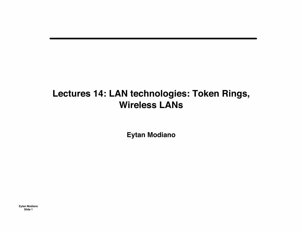
Token rings
• Token rings were developed by IBM in early 1980’s– IEEE Standard 802.5
• Token: a bit sequence– Token circulates around the ring
Busy token: 01111111 Free token: 01111110
• When a node wants to transmit– Wait for free token– Remove token from ring (replace with busy token)– Transmit message– When done transmitting, replace free token on ring
– Nodes must buffer 1 bit of data so that a free token can be changed to abusy token
• Token ring is basically a polling system Token does the polling
Token Ring
Eytan ModianoSlide 3
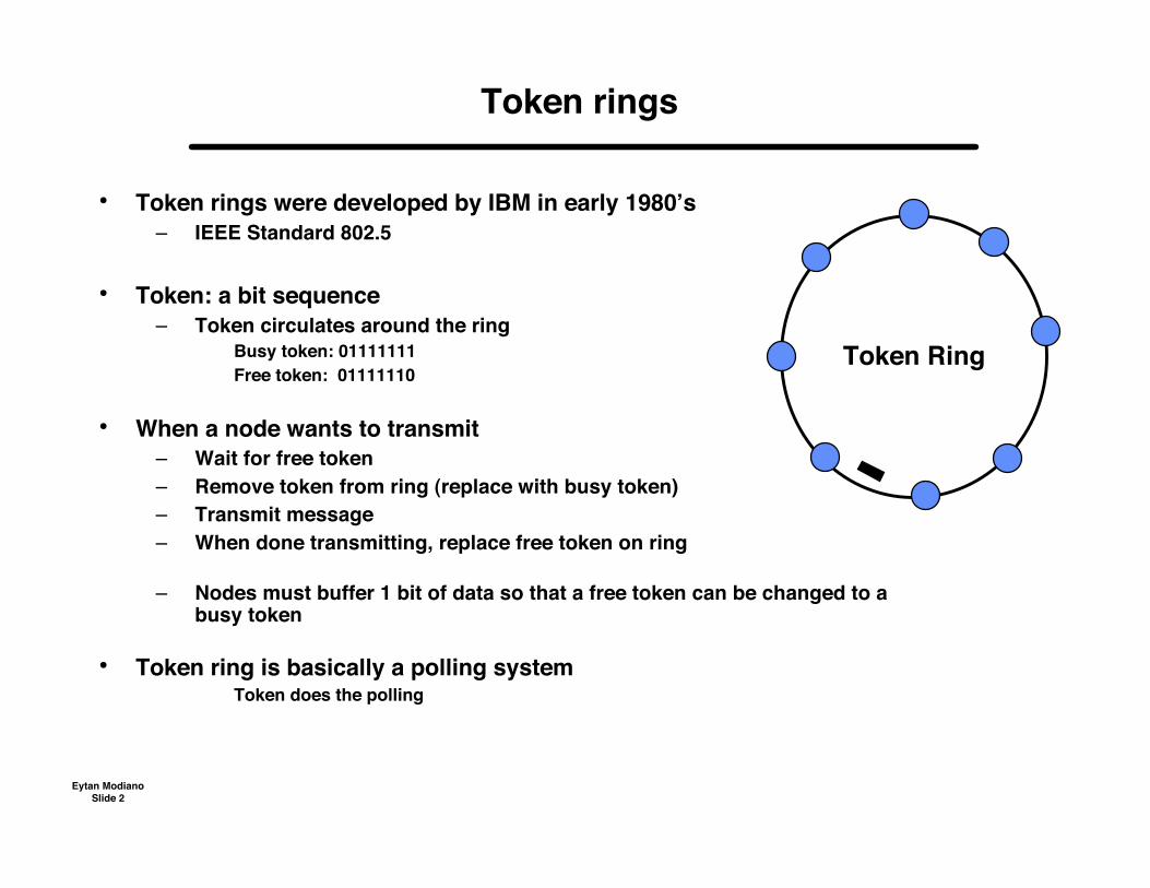
Release of token
• Release after transmission– Node replaces token on ring as soon as it is done transmitting the
packet– Next node can use token after short propagation delay
• Release after reception– Node releases token only after its own packet has returned to it
Serves as a simple acknowledgement mechanism
Eytan ModianoSlide 4
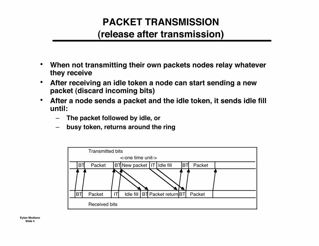
PACKET TRANSMISSION(release after transmission)
• When not transmitting their own packets nodes relay whateverthey receive
• After receiving an idle token a node can start sending a newpacket (discard incoming bits)
• After a node sends a packet and the idle token, it sends idle filluntil:
– The packet followed by idle, or– busy token, returns around the ring
BT
BTPacket return
BT Packet Idle fillBT New packet IT Packet
BT Packet IT Idle fill Packet
Transmitted bits
Received bits
<-one time unit->
BT
Eytan ModianoSlide 5
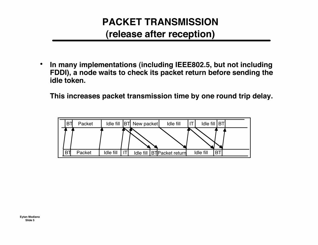
PACKET TRANSMISSION(release after reception)
• In many implementations (including IEEE802.5, but not includingFDDI), a node waits to check its packet return before sending theidle token.
This increases packet transmission time by one round trip delay.
BTBT Packet IT Idle fill Packet returnBTIdle fill
BT Packet BT New packetIdle fill Idle fill IT
Idle fill
Idle fill BT
Eytan ModianoSlide 6
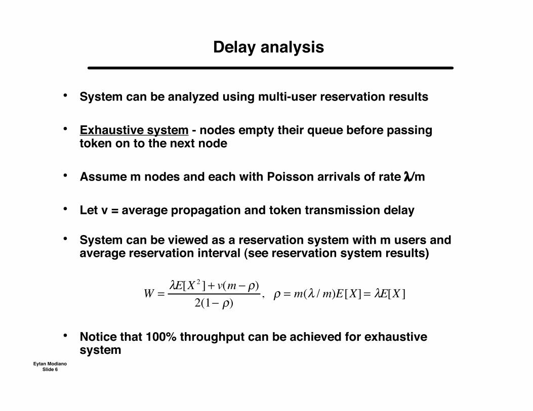
Delay analysis
• System can be analyzed using multi-user reservation results
• Exhaustive system - nodes empty their queue before passingtoken on to the next node
• Assume m nodes and each with Poisson arrivals of rate λ/m
• Let v = average propagation and token transmission delay
• System can be viewed as a reservation system with m users andaverage reservation interval (see reservation system results)
• Notice that 100% throughput can be achieved for exhaustivesystem
W =!E[X 2 ] + v(m " #)
2(1" #), # = m(! / m)E[X] = !E[X ]
Eytan ModianoSlide 7
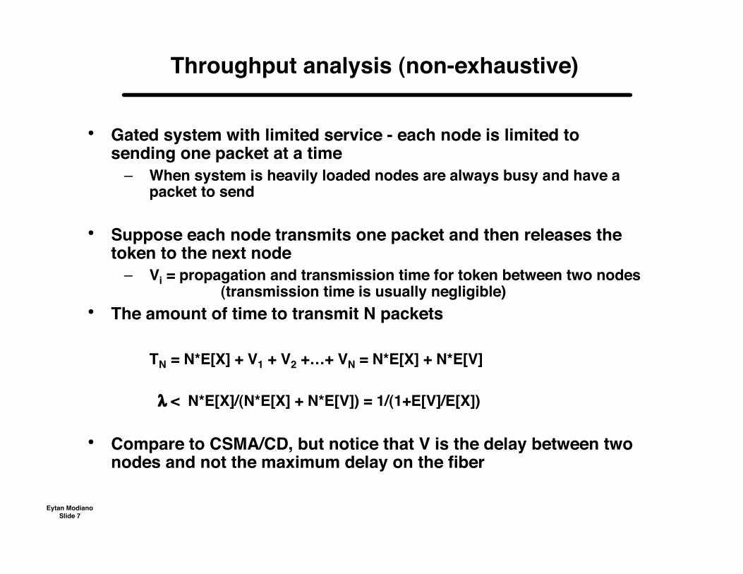
Throughput analysis (non-exhaustive)
• Gated system with limited service - each node is limited tosending one packet at a time
– When system is heavily loaded nodes are always busy and have apacket to send
• Suppose each node transmits one packet and then releases thetoken to the next node
– Vi = propagation and transmission time for token between two nodes(transmission time is usually negligible)
• The amount of time to transmit N packets
TN = N*E[X] + V1 + V2 +…+ VN = N*E[X] + N*E[V]
λ < N*E[X]/(N*E[X] + N*E[V]) = 1/(1+E[V]/E[X])
• Compare to CSMA/CD, but notice that V is the delay between twonodes and not the maximum delay on the fiber

Eytan ModianoSlide 8
Throughput analysis(token release after reception)
• Nodes release token only after it has returned to it• Again assume each node sends one packet at a time
• Total time to send ONE packet
• T = E[X] + V1 + V2 +…+ Vm + Vi
• T = E[X] + (m+1)E[V] =>
λ < E[X]/T = 1/(1+(m+1)E[V]/E[X])
Time to send token to next node
M nodes on the ring
Eytan ModianoSlide 9
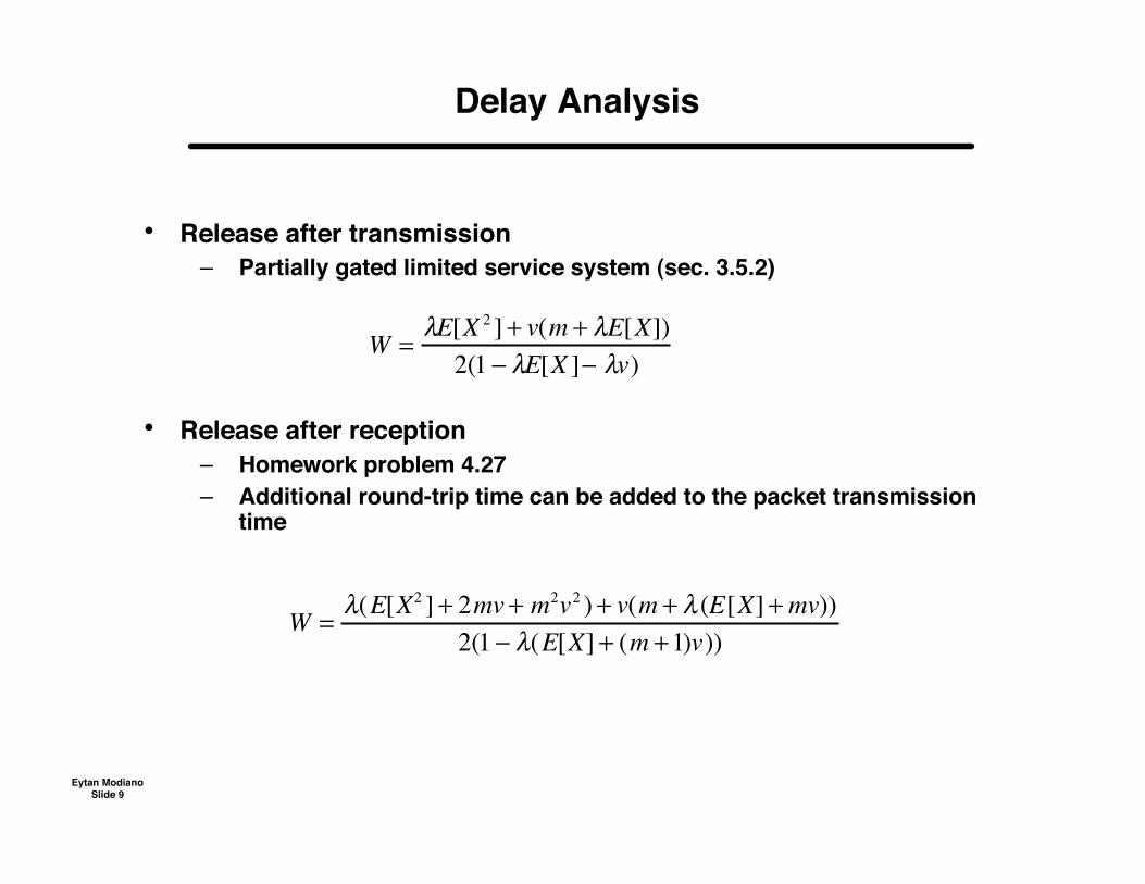
Delay Analysis
• Release after transmission– Partially gated limited service system (sec. 3.5.2)
• Release after reception– Homework problem 4.27– Additional round-trip time can be added to the packet transmission
time
W =!E[X 2 ] + v(m + !E[X])
2(1 " !E[X ]" !v)
W =!(E[X2 ] + 2mv + m2
v2 ) + v(m + ! (E[X] +mv))
2(1 " !(E[X] + (m +1)v))
Eytan ModianoSlide 10
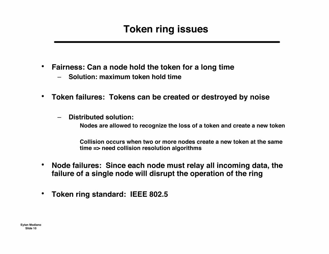
Token ring issues
• Fairness: Can a node hold the token for a long time– Solution: maximum token hold time
• Token failures: Tokens can be created or destroyed by noise
– Distributed solution: Nodes are allowed to recognize the loss of a token and create a new token
Collision occurs when two or more nodes create a new token at the sametime => need collision resolution algorithms
• Node failures: Since each node must relay all incoming data, thefailure of a single node will disrupt the operation of the ring
• Token ring standard: IEEE 802.5
Eytan ModianoSlide 11
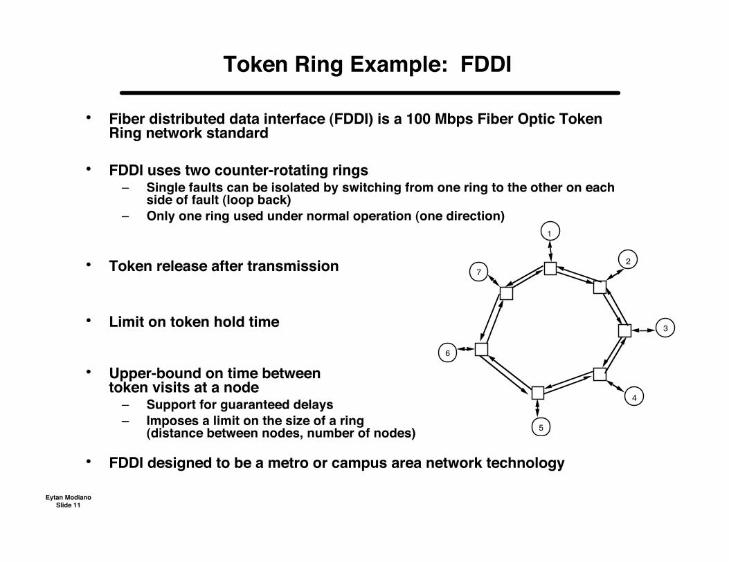
Token Ring Example: FDDI
• Fiber distributed data interface (FDDI) is a 100 Mbps Fiber Optic TokenRing network standard
• FDDI uses two counter-rotating rings– Single faults can be isolated by switching from one ring to the other on each
side of fault (loop back)– Only one ring used under normal operation (one direction)
• Token release after transmission
• Limit on token hold time
• Upper-bound on time betweentoken visits at a node
– Support for guaranteed delays– Imposes a limit on the size of a ring
(distance between nodes, number of nodes)
• FDDI designed to be a metro or campus area network technology
1
2
3
4
5
6
7
Eytan ModianoSlide 12
Resilient Packet Rings (RPR)(IEEE 802.17 standard)
• Uses two counter rotating rings– Both rings used for working traffic, using shortest path routing
• Buffer insertion mechanism (instead of token)– If no frame to forward, insert your own frame
• Failure recovery– Allows for both loop-back link protection and end-to-end path protection
• Sophisticated (i.e., complex) QoS mechanisms– Class A: low latency and low jitter– Class B: predictable latency and jitter– Class C: best effort
• Successful in MANs where reliability and QoS are critical
Eytan ModianoSlide 13
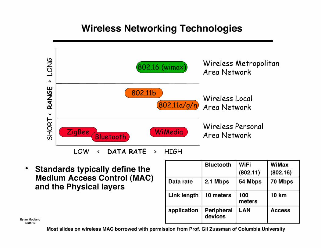
Wireless Networking Technologies
ZigBee
SHO
RT <
RANGE
> L
ON
G
LOW < DATA RATE > HIGH
Wireless PersonalArea Network
Wireless LocalArea Network
Bluetooth
802.11b
802.11a/g/n
Wireless MetropolitanArea Network802.16 (wimax)
WiMedia
• Standards typically define theMedium Access Control (MAC)and the Physical layers
Most slides on wireless MAC borrowed with permission from Prof. Gil Zussman of Columbia University
AccessLANPeripheraldevices
application
10 km100meters
10 metersLink length
70 Mbps54 Mbps2.1 MbpsData rate
WiMax(802.16)
WiFi(802.11)
Bluetooth

Eytan ModianoSlide 14
Medium Access Control (MAC)
• Nodes are scattered in a geographic area• Need to somehow coordinate the access to channel
– Transmission time, power, rate, etc.
• Centralized– Managed by an Access Point/Base Station
• Distributed– Random access (Aloha, CSMA, Ethernet)– Scheduled access
• Requirements– Throughput, delay, fairness, energy efficiency
2
3
5
6
4
7 8
1
Eytan ModianoSlide 15
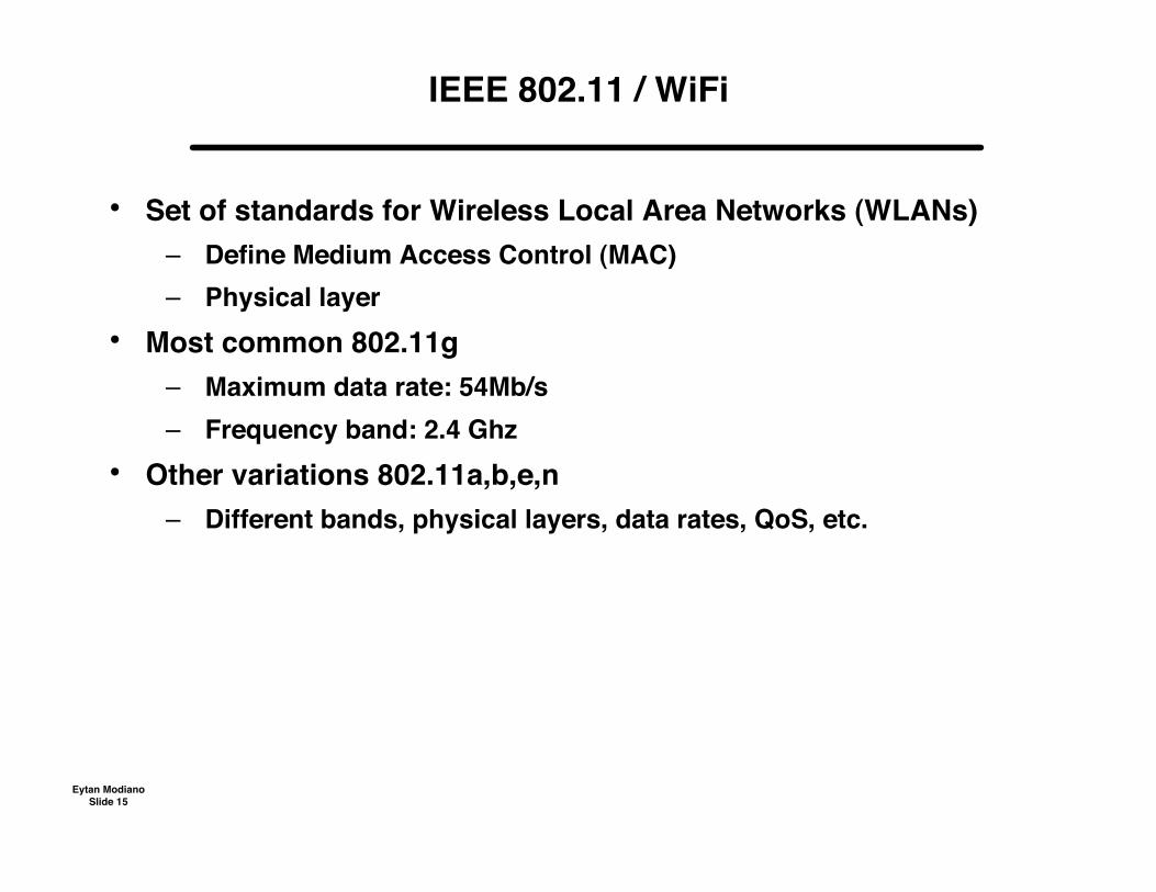
IEEE 802.11 / WiFi
• Set of standards for Wireless Local Area Networks (WLANs)– Define Medium Access Control (MAC)– Physical layer
• Most common 802.11g– Maximum data rate: 54Mb/s– Frequency band: 2.4 Ghz
• Other variations 802.11a,b,e,n– Different bands, physical layers, data rates, QoS, etc.
Eytan ModianoSlide 16
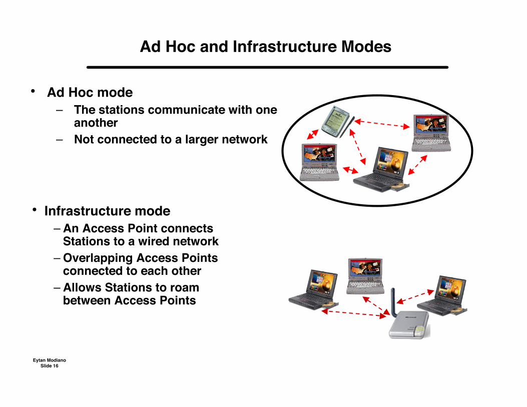
Ad Hoc and Infrastructure Modes
• Ad Hoc mode– The stations communicate with one
another– Not connected to a larger network
• Infrastructure mode– An Access Point connects
Stations to a wired network– Overlapping Access Points
connected to each other– Allows Stations to roam
between Access Points
Eytan ModianoSlide 17
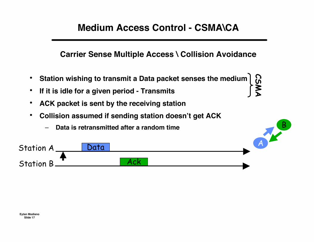
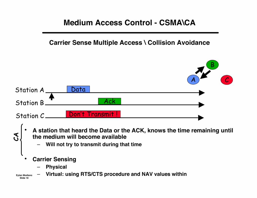
Medium Access Control - CSMA\CA
Carrier Sense Multiple Access \ Collision Avoidance
• Station wishing to transmit a Data packet senses the medium• If it is idle for a given period - Transmits• ACK packet is sent by the receiving station• Collision assumed if sending station doesn’t get ACK
– Data is retransmitted after a random time
CSMA
Data A
B
Station A
Station B Ack
Eytan ModianoSlide 18
Medium Access Control - CSMA\CA
Carrier Sense Multiple Access \ Collision Avoidance
DataA
B
Station A
Station B Ack
CA
• A station that heard the Data or the ACK, knows the time remaining untilthe medium will become available
– Will not try to transmit during that time
• Carrier Sensing– Physical– Virtual: using RTS/CTS procedure and NAV values within
C
Station C Don’t Transmit !
Eytan ModianoSlide 19
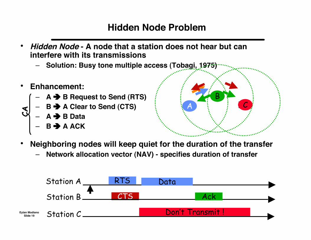
• Hidden Node - A node that a station does not hear but caninterfere with its transmissions
– Solution: Busy tone multiple access (Tobagi, 1975)
• Enhancement:– A B Request to Send (RTS)– B A Clear to Send (CTS)– A B Data– B A ACK
• Neighboring nodes will keep quiet for the duration of the transfer– Network allocation vector (NAV) - specifies duration of transfer
Hidden Node Problem
BA C
CA
RTS
CTS
Station A
Station B
Station C Don’t Transmit !
Data
Ack
Eytan ModianoSlide 20
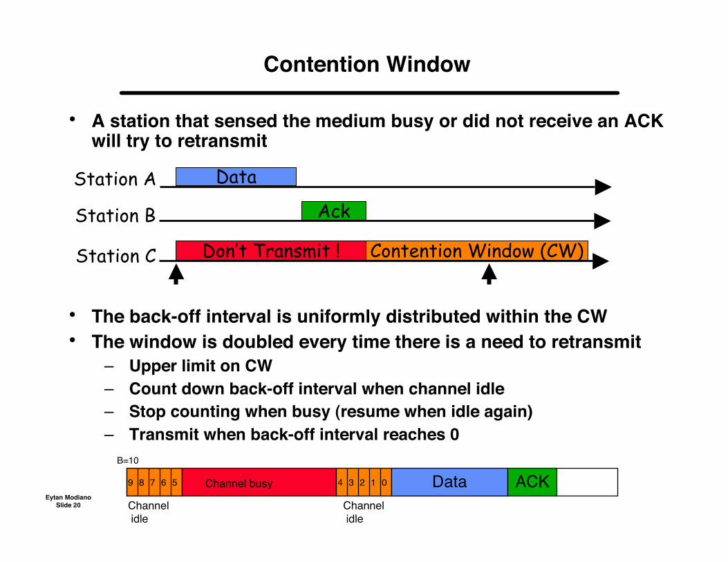
• A station that sensed the medium busy or did not receive an ACKwill try to retransmit
• The back-off interval is uniformly distributed within the CW• The window is doubled every time there is a need to retransmit
– Upper limit on CW– Count down back-off interval when channel idle– Stop counting when busy (resume when idle again)– Transmit when back-off interval reaches 0
Contention Window
Station A
Station B
Station C Don’t Transmit !
Data
Ack
Contention Window (CW)
B=10
Channel idle
9 8 7 6 5 Channel busy
Channel idle
4 3 2 1 0 Data ACK

Eytan ModianoSlide 21
Bluetooth
• Very short-range communications between computers and peripheraldevices
– E.g., replace connector cables such as usb
• Operates in 2.4 GHz unlicensed band– Uses spread-spectrum communications
Frequency hopping between 79 frequency channels New frequency every slot (625 µs)
• Piconet: master and 7 slave devices– All communication goes through the master
• ZigBee - a competing technology (will not discuss much)– Newer technology for low bandwidth, low power applications– Very simple and inexpensive– Designed for sensor networks; and communications between very inexpensive
devices (e.g., appliances)
Eytan ModianoSlide 22
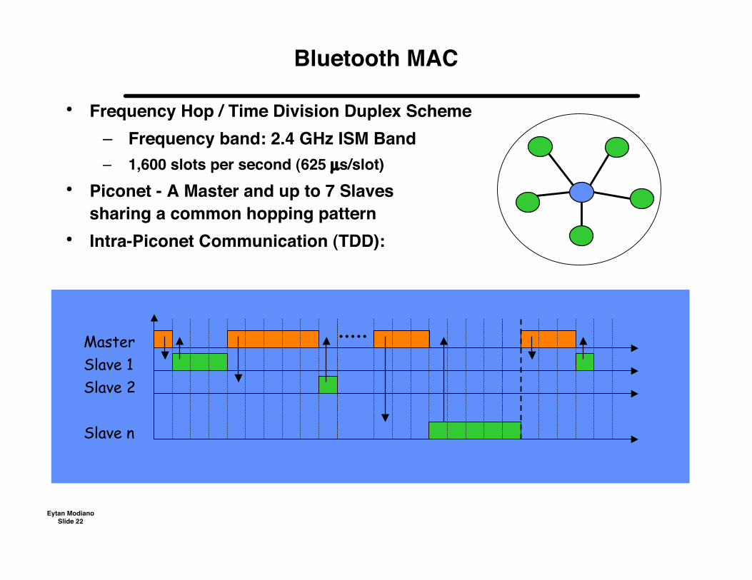
Bluetooth MAC
• Frequency Hop / Time Division Duplex Scheme– Frequency band: 2.4 GHz ISM Band– 1,600 slots per second (625 µs/slot)
• Piconet - A Master and up to 7 Slavessharing a common hopping pattern
• Intra-Piconet Communication (TDD):
MasterSlave 1Slave 2
Slave n
Eytan ModianoSlide 23
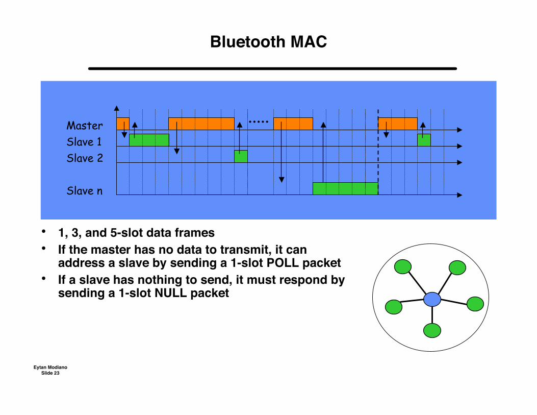
Bluetooth MAC
• 1, 3, and 5-slot data frames• If the master has no data to transmit, it can
address a slave by sending a 1-slot POLL packet• If a slave has nothing to send, it must respond by
sending a 1-slot NULL packet
MasterSlave 1Slave 2
Slave n
Eytan ModianoSlide 24
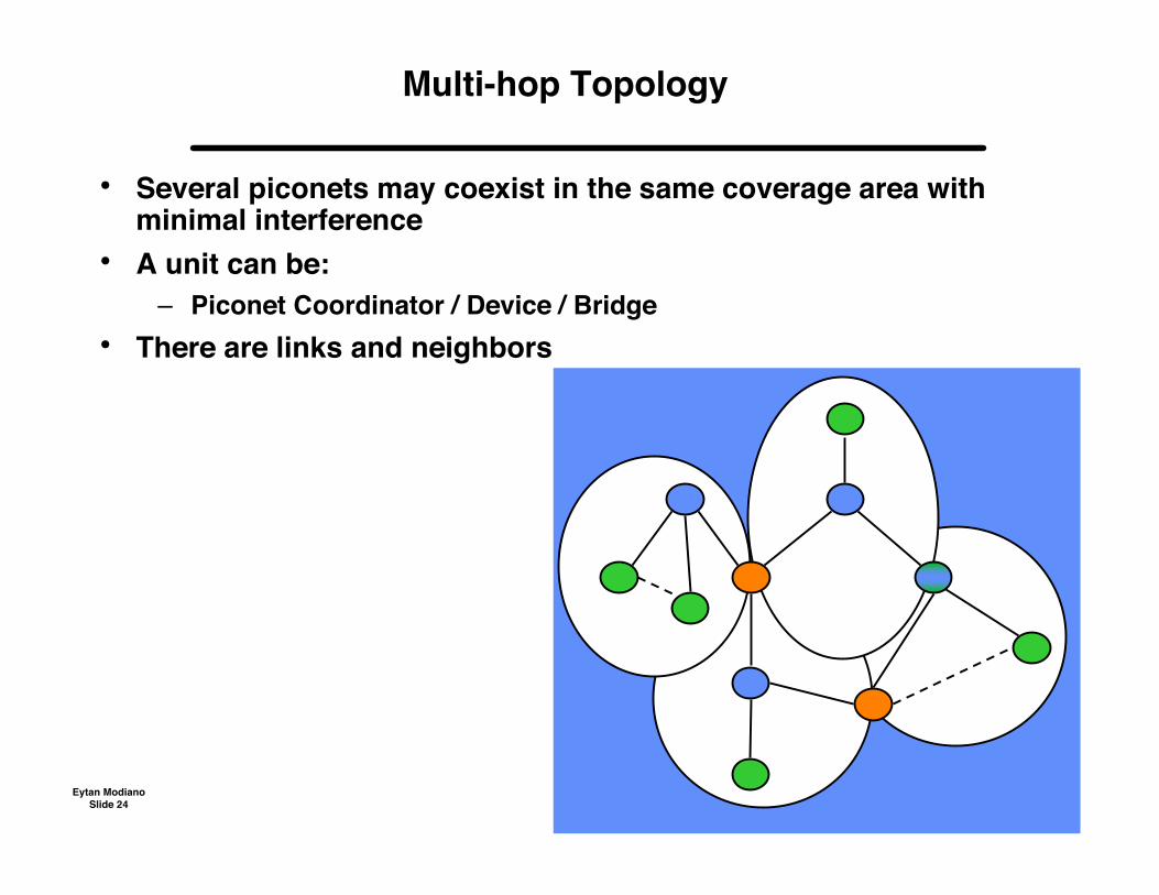
Multi-hop Topology
• Several piconets may coexist in the same coverage area withminimal interference
• A unit can be:– Piconet Coordinator / Device / Bridge
• There are links and neighbors
Eytan ModianoSlide 25
WiMAX (802.16)
• Access technology - metro area– Last (few) miles to home or business
• Data rates of up to 70 Mbps
• Physical layer– Microwave band: 10 to 66 GHz (line of sight)– Other bands also possible
• Connection oriented to offer QoS guarantees
• Medium access– Fixed assignment (guaranteed rate)– Reservations (polling)– Contention mechanism for best effort services
Eytan ModianoSlide 26
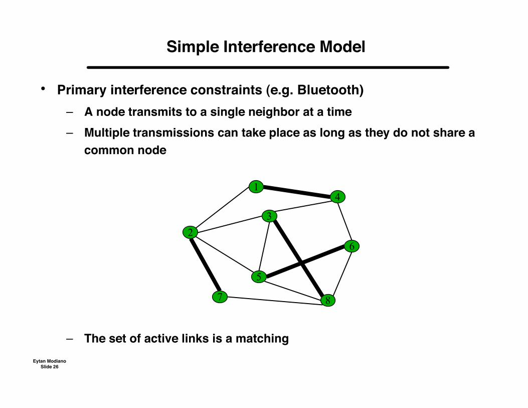
• Primary interference constraints (e.g. Bluetooth)– A node transmits to a single neighbor at a time– Multiple transmissions can take place as long as they do not share a
common node
– The set of active links is a matching
Simple Interference Model
2
1
3
5
6
4
7 8
Eytan ModianoSlide 27
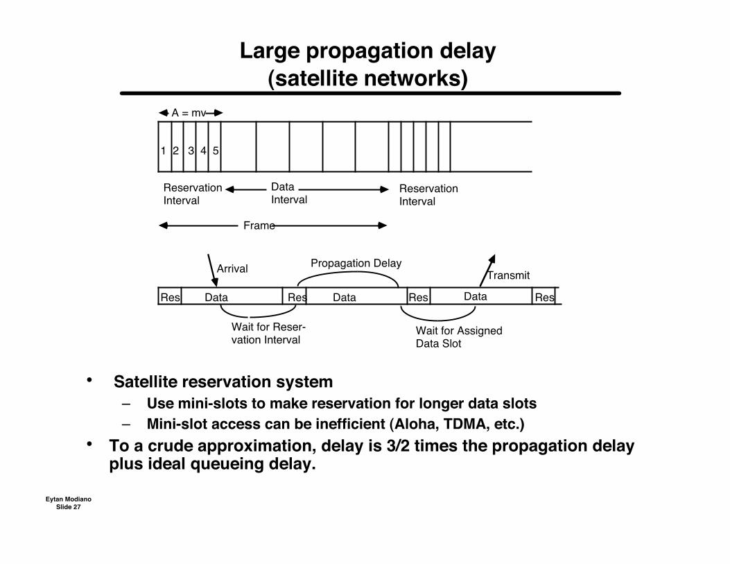
Large propagation delay(satellite networks)
• Satellite reservation system– Use mini-slots to make reservation for longer data slots– Mini-slot access can be inefficient (Aloha, TDMA, etc.)
• To a crude approximation, delay is 3/2 times the propagation delayplus ideal queueing delay.
1 2 3 4 5
A = mv
ReservationInterval
DataInterval
ReservationInterval
Frame
Res Data Res Data DataRes Res
Arrival
Wait for Reser-vation Interval
Propagation Delay
Wait for AssignedData Slot
Transmit
Eytan ModianoSlide 28
Satellite Reservations
• Frame length must exceed round-trip delay– Reservation slots during frame j are used to reserve data slots in
frame j+1– Variable length: serve all requests from frame j in frame j+1
Difficult to maintain synchronization Difficult to provide QoS (e.g., support voice traffic)
– Fixed length: Maintain a virtual queue of requests• Reservation mechanism
– Scheduler on board satellite– Scheduler on ground– Distributed queue algorithm
All nodes keep track of reservation requests and use the same algorithm tomake reservation
• Control channel access– TDMA: Simple but difficult to add more users– Aloha: Can support large number of users but collision resolution
can be difficult and add enormous delay
Eytan ModianoSlide 29
Packet multiple access summary
• Latency: Ratio of propagation delay to packet transmission time– GEO example: Dp = 0.5 sec, packet length = 1000 bits, R = 1Mbps
Latency = 500 => very high– LEO example: Dp = 0.1 sec
Latency = 100 => still very high– Over satellite channels data rate must be very low to be in a low
latency environment• Low latency protocols
– CSMA, Polling, Token Rings, etc.– Throughput ~ 1/(1+aα), α = latency, a = constant
• High latency protocols– Aloha is insensitive to latency, but generally low throughput
Very little delays– Reservation system can achieve high throughput
Delays for making reservations– Protocols can be designed to be a hybrid of Aloha and reservations
Aloha at low loads, reservations at high loads