Lectures 12 and 13 Wave Optics and Applications Chapter 25 ...
71
Lectures 12 and 13 Wave Optics and Applications Chapter 25 & 26-5
Transcript of Lectures 12 and 13 Wave Optics and Applications Chapter 25 ...
Lectures 12 and 13Wave Optics and Applications
Chapter 25 & 26-5

July 13, 2012 Chapter 25 - Wave Optics 2
Beyond Ray OpticsBeyond Ray Optics● Some of the physics
of light can be explained by rays Lenses Mirrors
● Some things cannot be explained by rays Diffraction
July 13, 2012 Chapter 25 - Wave Optics 3
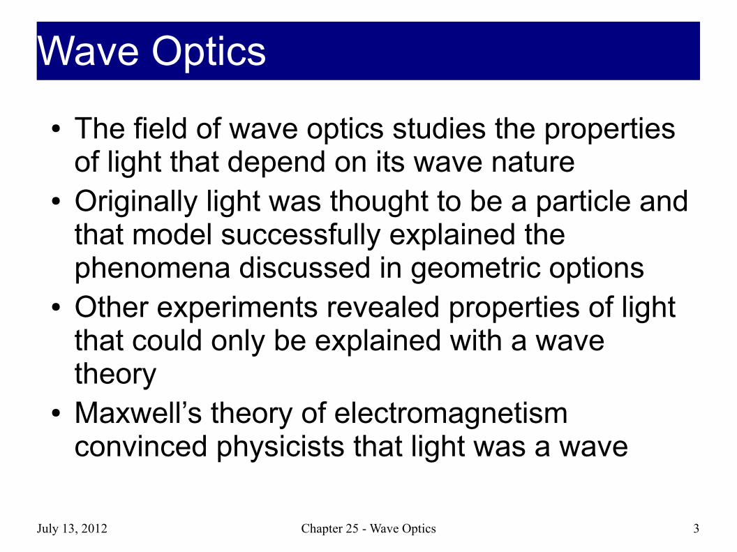
● The field of wave optics studies the properties of light that depend on its wave nature
● Originally light was thought to be a particle and that model successfully explained the phenomena discussed in geometric options
● Other experiments revealed properties of light that could only be explained with a wave theory
● Maxwell’s theory of electromagnetism convinced physicists that light was a wave
Wave OpticsWave Optics

July 13, 2012 Chapter 25 - Wave Optics 4
InterferenceInterference● Most phenomena that require a wave model of light involve interference● Discussed in Phys 220
Sound waves, waves on a string, etc. Constructive Interference
2 waves in phase add up to create a wave with bigger amplitude Destructive Interference
2 waves out of phase (180O) cancel each other out Phase Difference
< 90O: Semi-constructive > 90O: Semi-destructive

July 13, 2012 Chapter 25 - Wave Optics 5
Interference of LightInterference of Light● EM waves are oscillating E-fields and B-fields● More than one wave
Principle of Superposition Chapter 17
The E-Fields and B-Fields That make Up waves add
=Nothing after vector addition
=

July 13, 2012 Chapter 25 - Wave Optics 6
InterferenceInterference● Waves interfere (perfectly)
constructively when crests line up with crests
● Waves interfere (perfectly) destructively when crests line up with troughs
July 13, 2012 Chapter 25 - Wave Optics 7
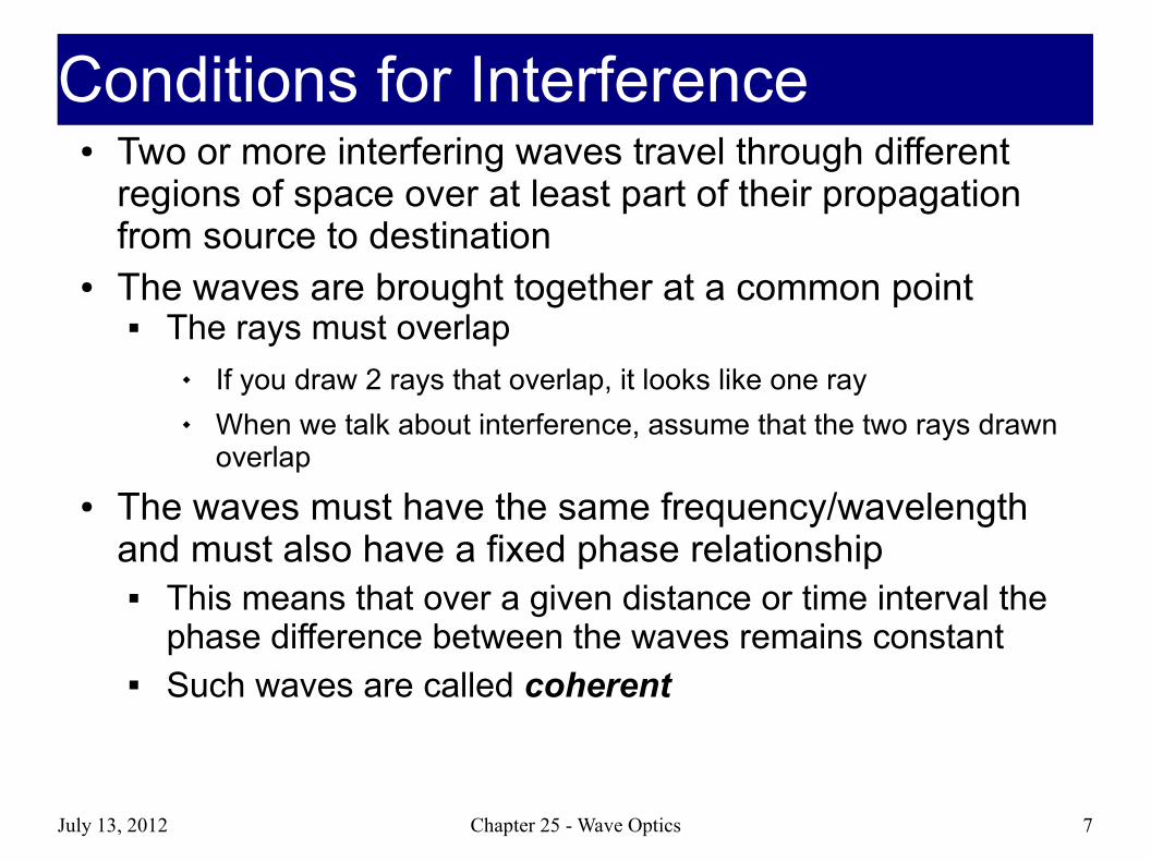
● Two or more interfering waves travel through different regions of space over at least part of their propagation from source to destination
● The waves are brought together at a common point The rays must overlap
If you draw 2 rays that overlap, it looks like one ray When we talk about interference, assume that the two rays drawn
overlap
● The waves must have the same frequency/wavelength and must also have a fixed phase relationship
This means that over a given distance or time interval the phase difference between the waves remains constant
Such waves are called coherent
Conditions for InterferenceConditions for Interference
July 13, 2012 Chapter 25 - Wave Optics 8
● The eye cannot follow variations of every cycle of the wave, so it averages the light intensity
● For waves to interfere constructively, they must stay in phase during the time the eye is averaging the intensity
● For waves to interfere destructively, they must stay out of phase during the averaging time
● Both of these possibilities involve the wave having precisely the same frequency
CoherenceCoherence

July 13, 2012 Chapter 25 - Wave Optics 9
● With slightly different frequencies, the interference changes from constructive to destructive and back
● Over a large number of cycles, the waves average no interference
Section 25.1
Coherence, cont.Coherence, cont.
July 13, 2012 Chapter 25 - Wave Optics 10
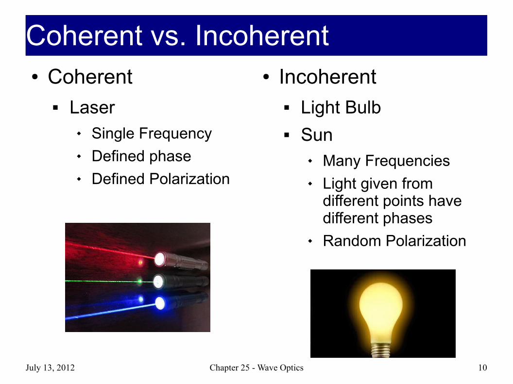
Coherent vs. IncoherentCoherent vs. Incoherent● Coherent
Laser Single Frequency Defined phase Defined Polarization
● Incoherent Light Bulb Sun
Many Frequencies Light given from
different points have different phases
Random Polarization
July 13, 2012 Chapter 25 - Wave Optics 11
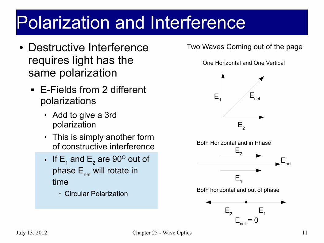
Polarization and InterferencePolarization and Interference● Destructive Interference
requires light has the same polarization E-Fields from 2 different
polarizations Add to give a 3rd
polarization This is simply another form
of constructive interference If E
1 and E
2 are 90O out of
phase Enet
will rotate in time
➢ Circular Polarization
Two Waves Coming out of the page
E1
E2
Enet
One Horizontal and One Vertical
Both Horizontal and in Phase
E2
E1
Enet
Both horizontal and out of phase
E1
E2
Enet
= 0

July 13, 2012 Chapter 25 - Wave Optics 12
Energy and BrightnessEnergy and Brightness● Just like in 220, the energy carried by a wave is given by
the square of the amplitude For EM waves it's the amplitude of an oscillating E-field
(from Ch. 23) Intensity = how bright something is
● Intensity and Interference (I1 + I
2 ≠ I
result)
Destructive interference → Enet
= 0 (darkness)
Constructive interference from coherent waves If E
net doubles then I quadruples (4X “brighter”)
➢ Human eyes are bad at measuring I (saturation effects)
Constructive interference from incoherent waves Different polarizations, E-Field gets added as vector Intensities just add (I
1 + I
2 = I
result)
I=12ε0 c E 0
2

July 13, 2012 Chapter 25 - Wave Optics 13
Homework ProblemsHomework Problems● https://chip.physics.purdue.edu/cgi-bin/221/summer2012/set?Homework/sm12s11 ● Incoherent case
Just add intensities
● Coherent Case Find E-fields from Intensities Add E-fields Use resulting E-field to find intensities
Destructive and constructive cases

July 13, 2012 Chapter 25 - Wave Optics 14
Identical Waves starting from different locationsIdentical Waves starting from different locations
● Constructive interference by starting in different spots
Destructive interference by starting in different spots
λ
λ/2

July 13, 2012 Chapter 25 - Wave Optics 15
Equivalent to Path Length DifferenceEquivalent to Path Length Difference● The distance of a path can be measured by the
number of crests (wavelengths) a wave takes to travel the path length
● Different paths will take different numbers of crests to complete If 2 coherent waves travel 2 different paths but end up
at the same spot they will interfere at the end If they are in phase at the starting point, it's like one got
a head start because it doesn't have to travel as far One wave travels one fewer wavelength = One wavelength
head start = Constructive Interference One wave travels one-half fewer wavelengths = One-half
wavelength head start = Destructive Interference
July 13, 2012 Chapter 25 - Wave Optics 16
Δ L=(m+12 )λ
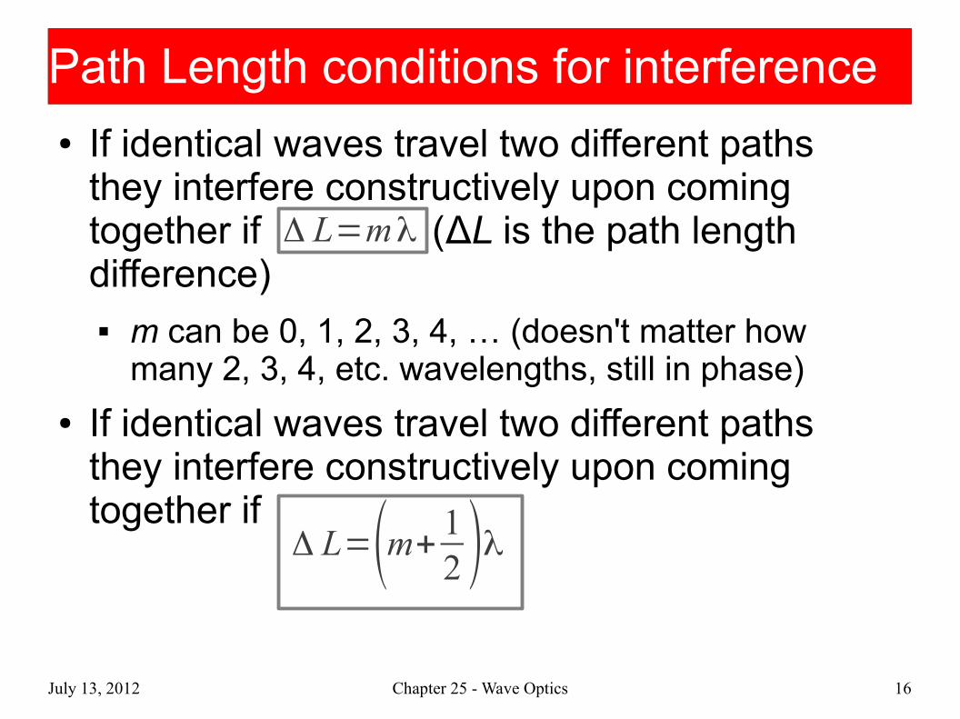
Path Length conditions for interferencePath Length conditions for interference● If identical waves travel two different paths
they interfere constructively upon coming together if (ΔL is the path length difference) m can be 0, 1, 2, 3, 4, … (doesn't matter how
many 2, 3, 4, etc. wavelengths, still in phase)
● If identical waves travel two different paths they interfere constructively upon coming together if
Δ L=mλ

July 13, 2012 Chapter 25 - Wave Optics 17
The hard partThe hard part
The rest of the chapter is basically calculating ΔL
Producing identical waves is a matter of spitting one wave into two or more

July 13, 2012 Chapter 25 - Wave Optics 18
Michelson InterferometerMichelson Interferometer● An experiment that led to
relativity
● The Michelson interferometer is based on the interference of reflected waves
● Two reflecting mirrors are mounted at right angles
● A third mirror is partially reflecting
Called a beam splitter Starting point for the 2 waves
is at the beam splitter
● Path Length Difference
ΔL = 2L2 - 2L
1

July 13, 2012 Chapter 25 - Wave Optics 19
Michelson Interferometer, cont.Michelson Interferometer, cont.● For constructive interference
ΔL = m λ● For destructive interference
ΔL = (m + ½) λ● m is an integer in both cases
● If the interference is constructive, the light intensity at the detector is large
Called a bright fringe● If the interference is destructive, the
light intensity at the detector is zero Called a dark fringe

July 13, 2012 Chapter 25 - Wave Optics 20
● Use the light from a laser and adjust the mirror to give constructive interference This corresponds to one of the bright fringes
● The mirror is then moved, changing the path length● The intensity changes from high to zero and back to
high every time the path length changes by one wavelength
● If the mirror moves through N bright fringes, the distance d traveled by the mirror is
2N
d λ=
Measuring LengthMeasuring Length

July 13, 2012 Chapter 25 - Wave Optics 21
● LIGO – Laser Interferometer Gravitational Wave Observatory
● Designed to detect very small vibrations associated with gravitational waves that arrive at the Earth from distant galaxies
● By using a long distance between the beam splitter and the mirrors, the LIGO interferometers are sensitive to very small percentage changes in that distance
LIGOLIGO
This is a roadThese are the arms of the interferometer

July 13, 2012 Chapter 25 - Wave Optics 22
● Assume a thin soap film rests on a flat glass surface● The upper surface of the soap film is similar to the beam
splitter in the interferometer● It reflects part of the incoming light and allows the rest to be
transmitted into the soap layer after refraction at the air-soap interface
ΔL = 2d (d is the thickness of the thin film)
Thin-Film InterferenceThin-Film Interference
July 13, 2012 Chapter 25 - Wave Optics 23
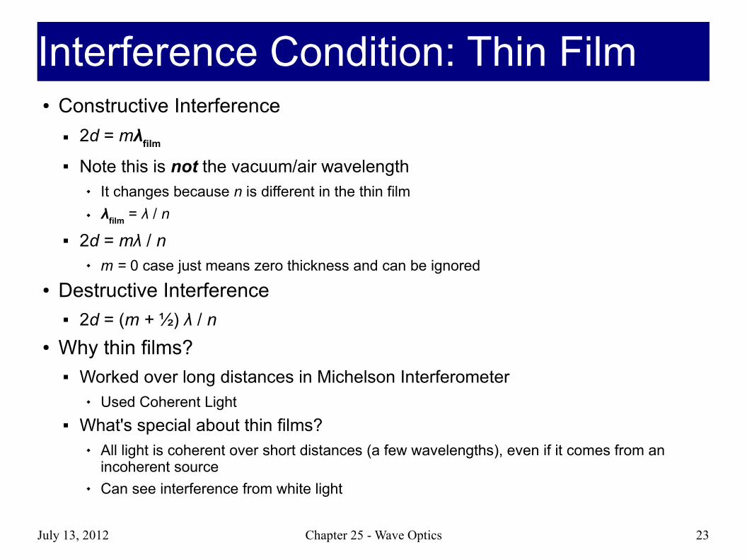
Interference Condition: Thin FilmInterference Condition: Thin Film● Constructive Interference
2d = mλfilm
Note this is not the vacuum/air wavelength It changes because n is different in the thin film λ
film = λ / n
2d = mλ / n m = 0 case just means zero thickness and can be ignored
● Destructive Interference 2d = (m + ½) λ / n
● Why thin films? Worked over long distances in Michelson Interferometer
Used Coherent Light What's special about thin films?
All light is coherent over short distances (a few wavelengths), even if it comes from an incoherent source
Can see interference from white light

July 13, 2012 Chapter 25 - Wave Optics 24
● If that was all there was to thin films, the last slide would have gotten a red title
● When a light wave reflects from a surface it may be inverted
Inversion corresponds to a phase change of 180° Crest becomes trough and vice versa
● There is a phase change whenever the index of refraction on the incident side is less than the index of refraction of the opposite side
● If the index of refraction is larger on the incident side the reflected ray in not inverted and there is no phase change
Phase Change and ReflectionPhase Change and Reflection

July 13, 2012 Chapter 25 - Wave Optics 25
Phase Change and Reflection, DiagramPhase Change and Reflection, Diagram

July 13, 2012 Chapter 25 - Wave Optics 26
Phase Changes, cont.Phase Changes, cont.● If there's a phase change at the boundary, the
path of the wave looks like this:
● Equivalent to adding half a wavelength
Extra half wavlength

July 13, 2012 Chapter 25 - Wave Optics 27
Thin Film w/ Phase ChangesThin Film w/ Phase Changes● No phase changes at boundaries (very rare, usually one of the layers is air)
Constructive Interference 2d = mλ / n
Destructive Interference 2d = (m + ½) λ / n
● Only one phase change at boundaries Constructive Interference
2d = (m + ½) λ / n Destructive Interference
2d = (m + 1) λ / n = mλ / n
● Phase change at both boundaries Cancel Out Constructive Interference
2d = mλ / n Destructive Interference
2d = (m + ½) λ / n
July 13, 2012 Chapter 25 - Wave Optics 28
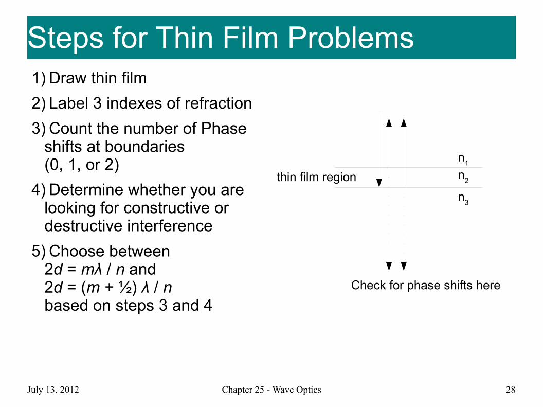
Steps for Thin Film ProblemsSteps for Thin Film Problems1) Draw thin film
2) Label 3 indexes of refraction
3) Count the number of Phase shifts at boundaries(0, 1, or 2)
4) Determine whether you are looking for constructive or destructive interference
5) Choose between 2d = mλ / n and 2d = (m + ½) λ / nbased on steps 3 and 4
n1
n2
n3
thin film region
Check for phase shifts here

July 13, 2012 Chapter 25 - Wave Optics 29
PracticePractice● Homework Problem 11.5
https://chip.physics.purdue.edu/cgi-bin/221/summer2012/tma?Homework/sm12s11/GB25P009.pr
● Soap Bubble Demo

July 13, 2012 Chapter 25 - Wave Optics 30
● Nearly any flat piece of glass may act like a partially reflecting mirror
● To avoid reductions in intensity due to this reflection, antireflective coatings may be used
● The coating makes a lens appear slightly dark in color when viewed in reflected light
Antireflection CoatingsAntireflection Coatings
July 13, 2012 Chapter 25 - Wave Optics 31
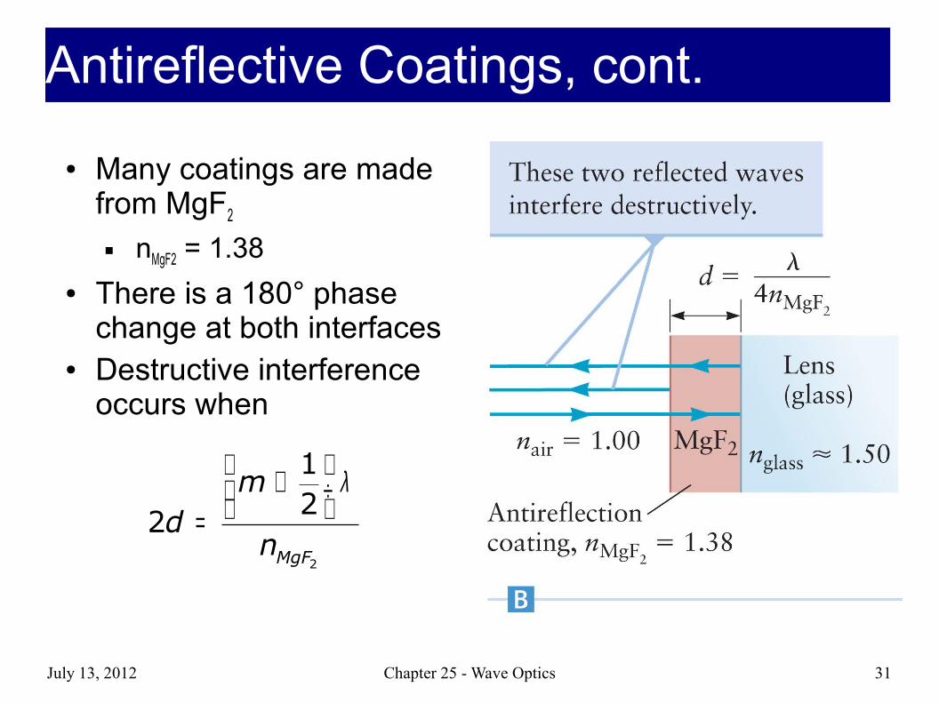
● Many coatings are made from MgF2
nMgF2 = 1.38
● There is a 180° phase change at both interfaces
● Destructive interference occurs when
2
12
2MgF
md
n
λ + ÷ =
Antireflective Coatings, cont.Antireflective Coatings, cont.

July 13, 2012 Chapter 25 - Wave Optics 32
Splitting light with small openingSplitting light with small opening● So far we've used partial reflections to split light into 2
coherent waves● We can also use small openings
Qualitative description of light going through a slit Wide slit – explained by ray optics (shadow where the light is blocked) Small slit – wave optics - diffraction
July 13, 2012 Chapter 25 - Wave Optics 33
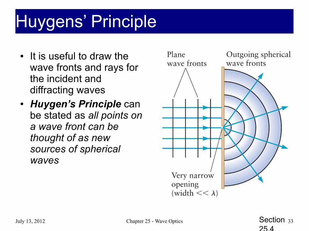
● It is useful to draw the wave fronts and rays for the incident and diffracting waves
● Huygen’s Principle can be stated as all points on a wave front can be thought of as new sources of spherical waves
Section 25.4
Huygens’ PrincipleHuygens’ Principle

July 13, 2012 Chapter 25 - Wave Optics 34
● Water wave example of single-slit diffraction
All types of waves undergo single-slit diffraction
Water waves have a wavelength easily visible
● Diffraction is the bending or spreading of a wave when it passes through an opening
Section 25.4
Water Wave ExampleWater Wave Example
July 13, 2012 Chapter 25 - Wave Optics 35
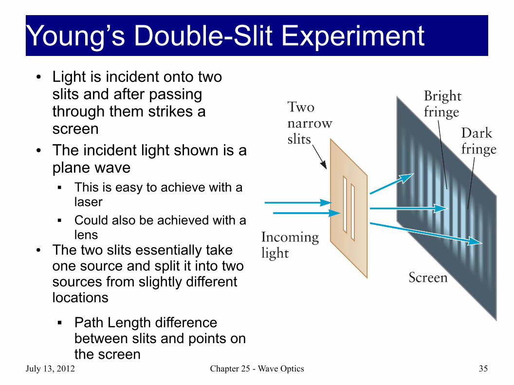
● Light is incident onto two slits and after passing through them strikes a screen
● The incident light shown is a plane wave
This is easy to achieve with a laser
Could also be achieved with a lens
● The two slits essentially take one source and split it into two sources from slightly different locations
Path Length difference between slits and points on the screen
Young’s Double-Slit ExperimentYoung’s Double-Slit Experiment

July 13, 2012 Chapter 25 - Wave Optics 36
● Candle would be incoherent Filtered by going through small opening Resulting spherical wave is coherent
because it acts as a uniform source
● The experiment satisfies the general requirements for interference
The interfering waves travel through different regions of space as they travel through different slits
The waves come together at a common point on the screen where they interfere
The waves are coherent because they come from the same source
Young didn't have a laserYoung didn't have a laser

July 13, 2012 Chapter 25 - Wave Optics 37
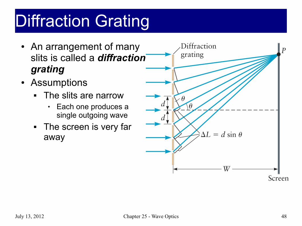
● Determine the path length between each slit and the screen
● Assume W is very large● If the slits are separated
by a distance d, then the difference in length between the paths of the two rays is ΔL = d sin θ
Section 25.5
Path Length Difference between slitsPath Length Difference between slits

July 13, 2012 Chapter 25 - Wave Optics 38
● The angle θ varies as you move along the screen
● Each bright fringe corresponds to
● Negative values of m indicate that the path to those points on the screen from the lower slit is shorter than the path from the upper slit
● Dark areas in between exhibit destructive interference
Interference conditionsInterference conditions
d sin θ=mλ
d sinθ=(m+12)λ

July 13, 2012 Chapter 25 - Wave Optics 39
TrigTrig
sinθ=h
√(h2+W 2)
Usually W >> h so …
sinθ≈hW

July 13, 2012 Chapter 25 - Wave Optics 40
Steps to do double slit problemsSteps to do double slit problems1) Draw a line for where the double slits
are
2) Draw a line for where the screen is
3) Draw the triangle connecting the central maximum (directly across from slits) to the slits to the bright or dark fringe you are interested in
4) Setup or d is the distance between slits
5) Unless solving for θ replace sin θ with the approximation h / W
W
h
d sin θ=mλ
θ
d sinθ=(m+1 /2)λ

July 13, 2012 Chapter 25 - Wave Optics 41
How many Fringes will you seeHow many Fringes will you see● What's the max value
for θ?● What is the m that
corresponds to that θ?● + and – fringe for each
m plus m = 0

July 13, 2012 Chapter 25 - Wave Optics 42
● Slits may be narrow enough to exhibit diffraction but not so narrow that they can be treated as a single point source of waves
● Assume the single slit has a width, w● Light is diffracted as it passes through the slit and then
propagates to the screen
Section 25.6
Single-Slit InterferenceSingle-Slit Interference

July 13, 2012 Chapter 25 - Wave Optics 43
● With a single slit, light does not appear to be split into separate sources
● The key to the calculation of where the fringes occur is Huygen’s principle
● All points across the slit act as wave sources
● These different waves interfere at the screen
● For analysis, divide the slit into two parts
Section 25.6
How do you get interference?How do you get interference?Where does interference come from?Where does interference come from?

July 13, 2012 Chapter 25 - Wave Optics 44
● Light from Point A1 can
interfere with light from point B
1
● Path length difference calculation is similar to double slit
Last time we used d, spacing between slits
For single slit we use w/2, the spacing between a point and another point half a slit width away
How do you get interference?How do you get interference?Where does interference come from?Where does interference come from?
Δ L=w2
sinθ
July 13, 2012 Chapter 25 - Wave Optics 45
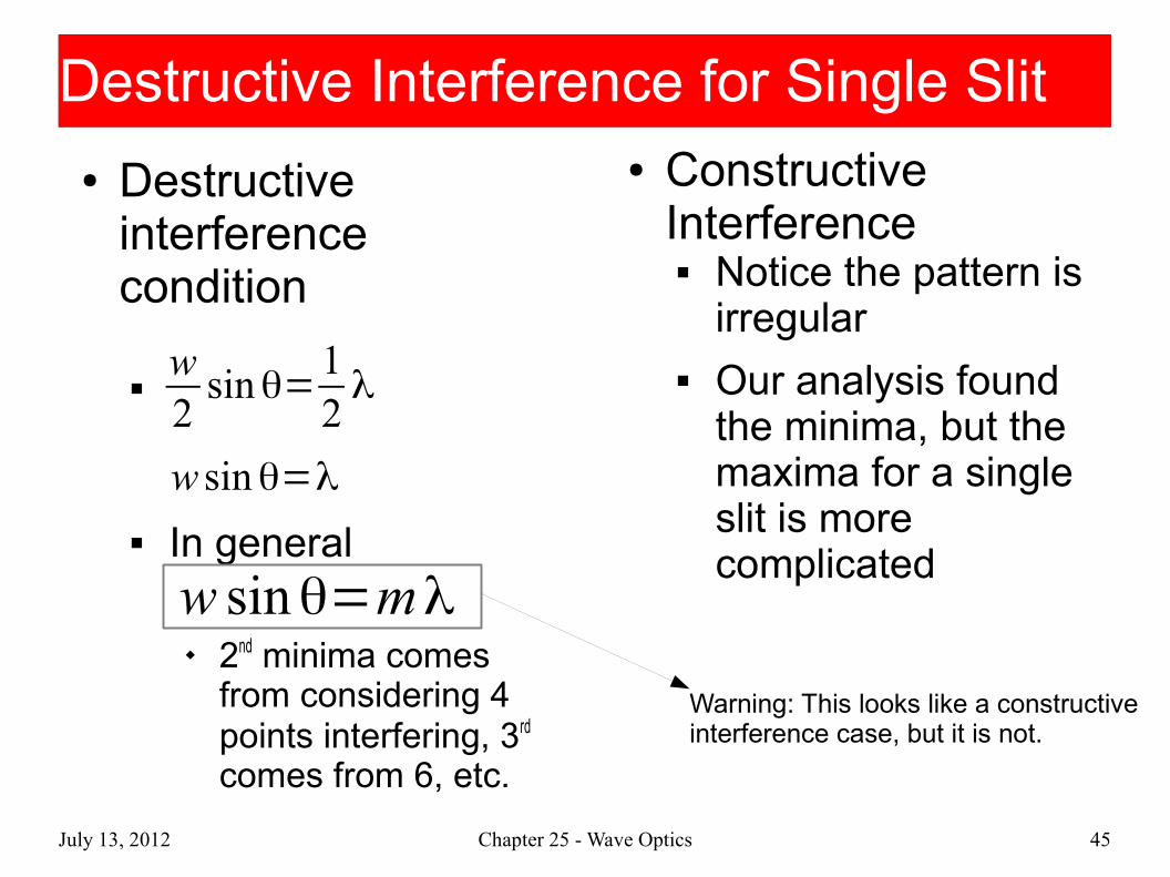
● Destructive interference condition
In general
2nd minima comes from considering 4 points interfering, 3rd comes from 6, etc.
Destructive Interference for Single Slit Destructive Interference for Single Slit
w2
sinθ=12λ
w sinθ=λ
w sinθ=mλ
Warning: This looks like a constructive interference case, but it is not.
● Constructive Interference Notice the pattern is
irregular Our analysis found
the minima, but the maxima for a single slit is more complicated

July 13, 2012 Chapter 25 - Wave Optics 46
Steps to doing Single Slit problemsSteps to doing Single Slit problems● Same as Double slit● Same approximation
for sin θ● Classic problem
Find the width of the central maximum
Distance between 2 minima around it (2h)
W
h
July 13, 2012 Chapter 25 - Wave Optics 47
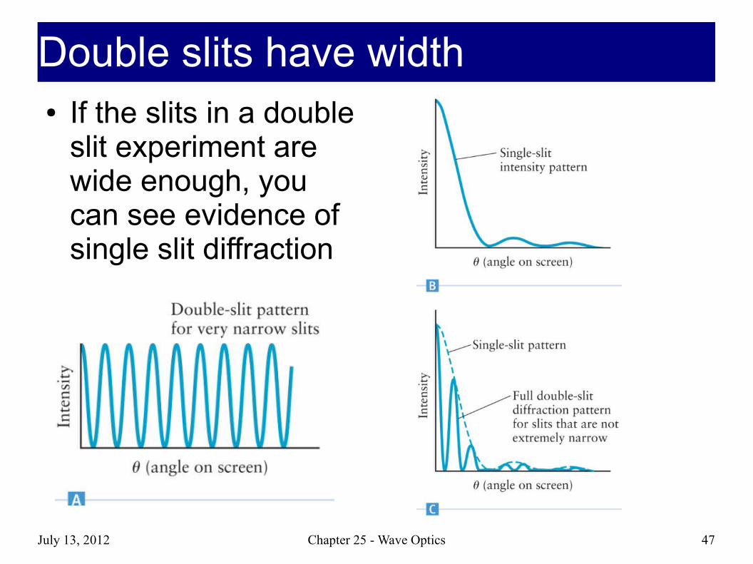
Double slits have widthDouble slits have width● If the slits in a double
slit experiment are wide enough, you can see evidence of single slit diffraction
July 13, 2012 Chapter 25 - Wave Optics 48
● An arrangement of many slits is called a diffraction grating
● Assumptions The slits are narrow
Each one produces a single outgoing wave
The screen is very far away
Diffraction GratingDiffraction Grating
July 13, 2012 Chapter 25 - Wave Optics 49
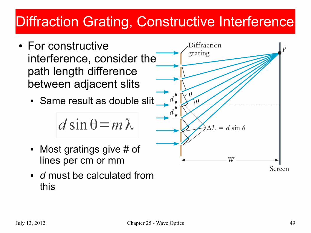
Diffraction Grating, Constructive InterferenceDiffraction Grating, Constructive Interference
● For constructive interference, consider the path length difference between adjacent slits Same result as double slit
Most gratings give # of lines per cm or mm
d must be calculated from this
d sinθ=mλ

July 13, 2012 Chapter 25 - Wave Optics 50
Diffraction Grating PatternsDiffraction Grating Patterns● We won't worry about
destructive interference because it's complicated and a function of the number of slits Qualitative behavior
seen in picture Many slits = almost
complete destructive interference between bright fringes

July 13, 2012 Chapter 25 - Wave Optics 51
● A spectrometer is a device used to measure the wavelength of light based on a diffraction grating
● A diffraction grating will produce an intensity pattern on the screen for each color
● The different colors will have different angles and different places on the screen
● Separation between spots depends on wavelength
Section 25.7
SpectrometersSpectrometers

July 13, 2012 Chapter 25 - Wave Optics 52
Separating out ColorSeparating out Color● Diffraction gratings
can separate out different colors of the rainbow like prisms But smaller λ =
smaller θ Shorter wavelengths
get bent less Rainbow colors are in
the reverse order from a prism
July 13, 2012 Chapter 25 - Wave Optics 53
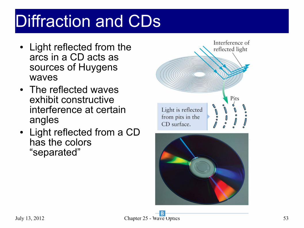
● Light reflected from the arcs in a CD acts as sources of Huygens waves
● The reflected waves exhibit constructive interference at certain angles
● Light reflected from a CD has the colors “separated”
Diffraction and CDsDiffraction and CDs
● The pattern of pits on the top surface is used to encode information on the CD
● The top surface is coated with a thin layer of aluminum to make it reflecting
● It is then covered with a protective layer of lacquer● The label is placed over the lacquer● The pits are arranged in a long spiral track● Information encoded in the pits is read by reflecting a laser
beam from the aluminum surface● Laser light passes in and out through the bottom surface of
the plastic, so the surface must be kept clean
Section 26.5
CD StructureCD Structure
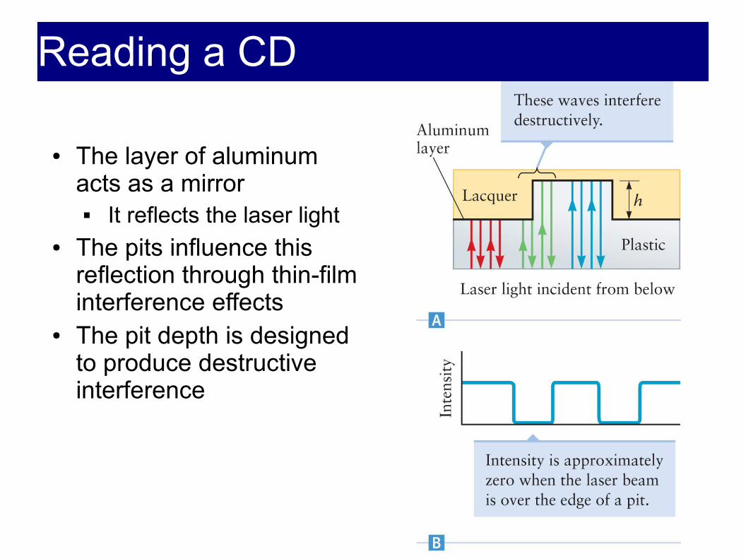
● The layer of aluminum acts as a mirror
It reflects the laser light● The pits influence this
reflection through thin-film interference effects
● The pit depth is designed to produce destructive interference
Reading a CDReading a CD

July 13, 2012 Chapter 25 - Wave Optics 56
Diffraction GlassesDiffraction Glasses● Fireworks Shows● Christmas Lights

July 13, 2012 Chapter 25 - Wave Optics 57
Two Sources, Single SlitTwo Sources, Single Slit● Can you see two
distinct peaks from each of the two sources? If the peaks from
diffraction stay far enough appart two peaks can still be seen when they are added (left)
If they get too close the sum becomes one peak (right)
July 13, 2012 Chapter 25 - Wave Optics 58
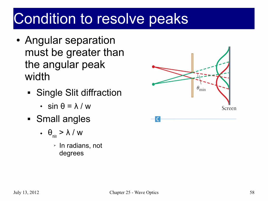
Condition to resolve peaksCondition to resolve peaks● Angular separation
must be greater than the angular peak width Single Slit diffraction
sin θ = λ / w Small angles
θmin > λ / w
➢ In radians, not degrees
July 13, 2012 Chapter 25 - Wave Optics 59
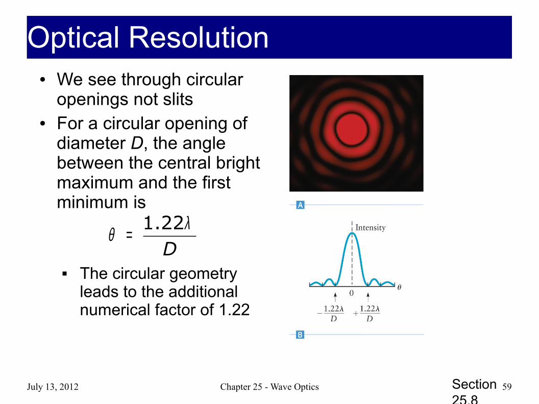
● We see through circular openings not slits
● For a circular opening of diameter D, the angle between the central bright maximum and the first minimum is
The circular geometry leads to the additional numerical factor of 1.22
D1.22λθ =
Section 25.8
Optical ResolutionOptical Resolution
July 13, 2012 Chapter 25 - Wave Optics 60
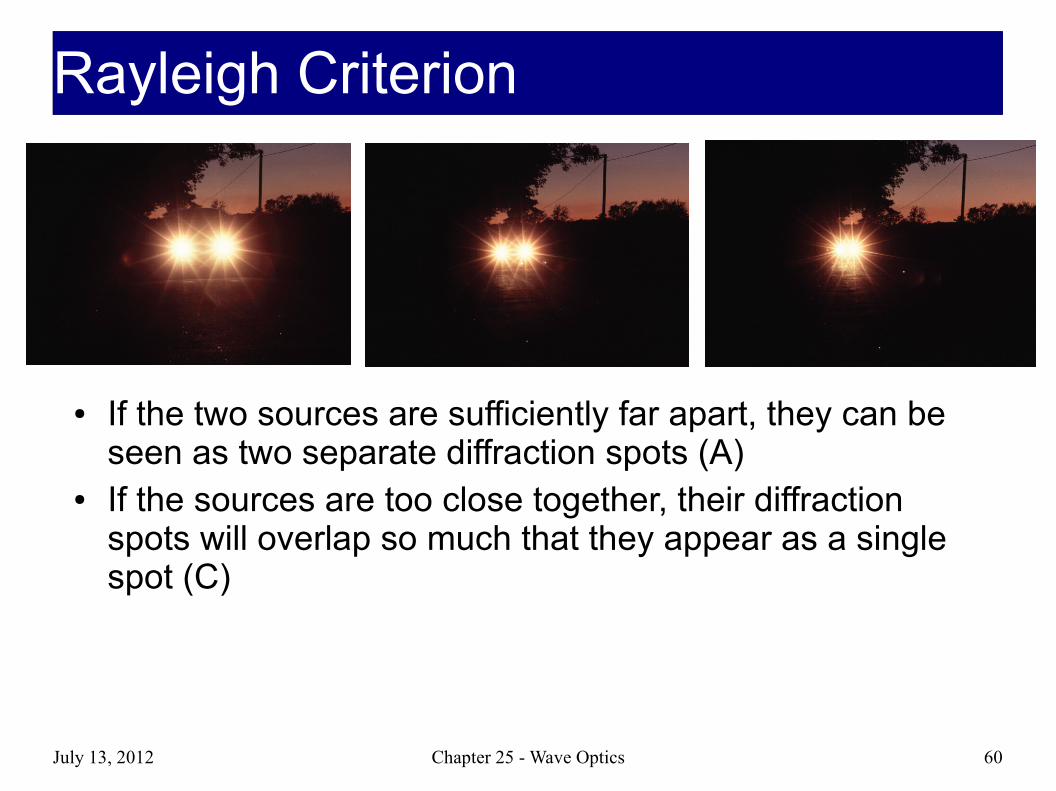
● If the two sources are sufficiently far apart, they can be seen as two separate diffraction spots (A)
● If the sources are too close together, their diffraction spots will overlap so much that they appear as a single spot (C)
Rayleigh CriterionRayleigh Criterion
July 13, 2012 Chapter 25 - Wave Optics 61
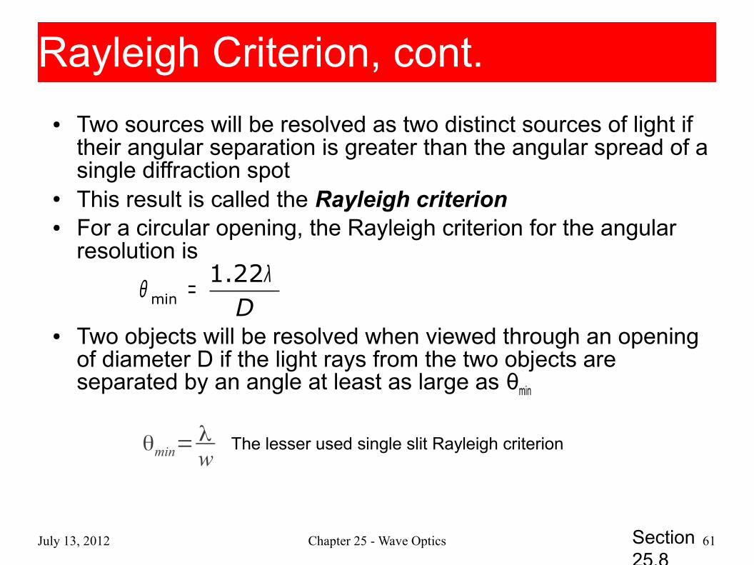
● Two sources will be resolved as two distinct sources of light if their angular separation is greater than the angular spread of a single diffraction spot
● This result is called the Rayleigh criterion● For a circular opening, the Rayleigh criterion for the angular
resolution is
● Two objects will be resolved when viewed through an opening of diameter D if the light rays from the two objects are separated by an angle at least as large as θmin
Dmin
1.22λθ =
Section 25.8
Rayleigh Criterion, cont.Rayleigh Criterion, cont.
θmin=λw
The lesser used single slit Rayleigh criterion
July 13, 2012 Chapter 25 - Wave Optics 62
Resolution of telescopes/microscopesResolution of telescopes/microscopes● The resolution of telescopes and microscopes
is ultimately limited by the diameter of the lenses/mirrors used There is no theoretical limit to the allowed
magnification from geometrical optics But diffraction will cause objects that start to
approach the wavelength of light to “smear” together
This is known as the diffraction limit
July 13, 2012 Chapter 25 - Wave Optics 63
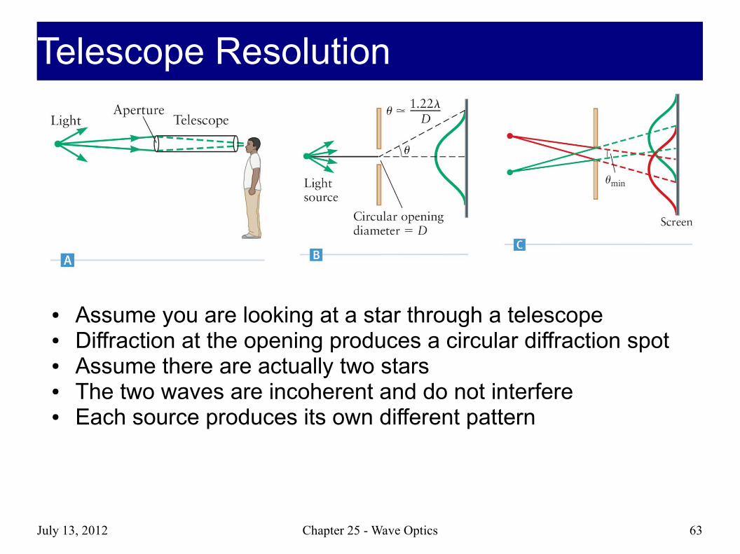
● Assume you are looking at a star through a telescope● Diffraction at the opening produces a circular diffraction spot● Assume there are actually two stars● The two waves are incoherent and do not interfere● Each source produces its own different pattern
Telescope ResolutionTelescope Resolution
July 13, 2012 Chapter 25 - Wave Optics 64
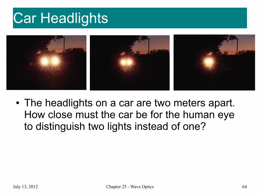
Car HeadlightsCar Headlights
● The headlights on a car are two meters apart. How close must the car be for the human eye to distinguish two lights instead of one?
July 13, 2012 Chapter 25 - Wave Optics 65
TelescopesTelescopes● You want to be able to resolve two stars in the
sky using a telescope. Should you buy the one with the larger mirror or the one with the longer focal length?
● Is the magnification important?

July 13, 2012 Chapter 25 - Wave Optics 66
CD's and Diffraction LimitCD's and Diffraction Limit● CD's are read with 780 nm lasers
780 MB of data
● DVD's are read using 660 nm lasers 8.4 GB of data
● Blue Rays are read with 445 nm laser 25 GB of data
● What does this have to do with diffraction?
July 13, 2012 Chapter 25 - Wave Optics 67
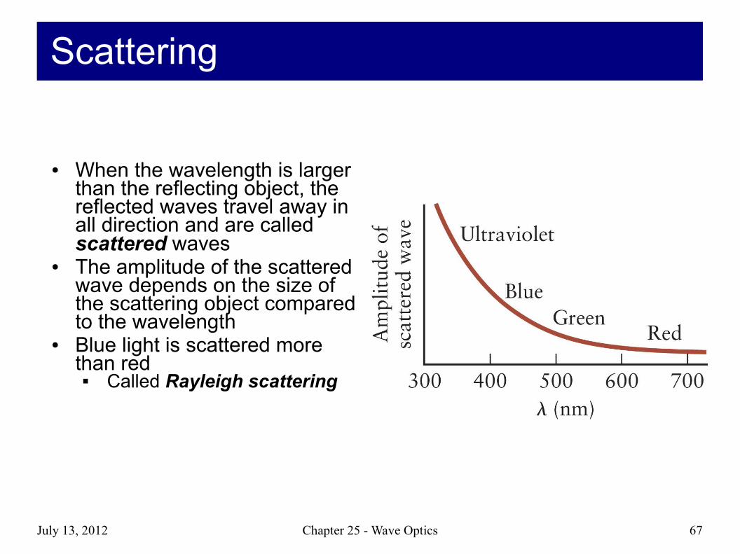
● When the wavelength is larger than the reflecting object, the reflected waves travel away in all direction and are called scattered waves
● The amplitude of the scattered wave depends on the size of the scattering object compared to the wavelength
● Blue light is scattered more than red
Called Rayleigh scattering
ScatteringScattering
July 13, 2012 Chapter 25 - Wave Optics 68
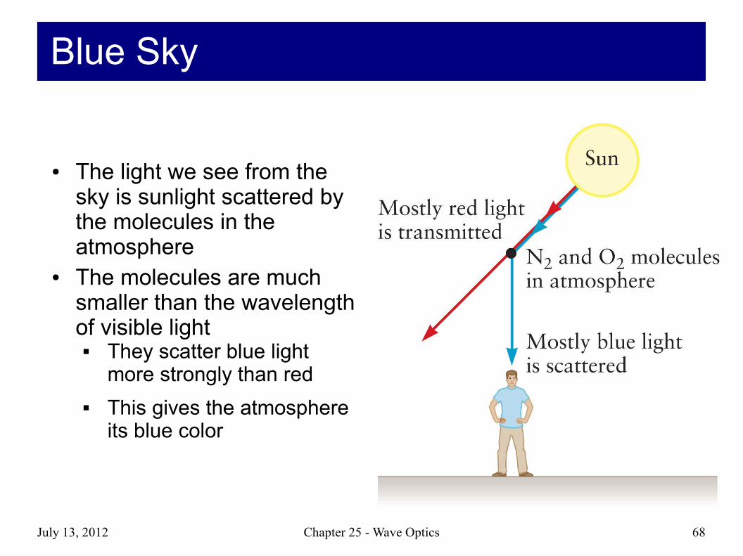
● The light we see from the sky is sunlight scattered by the molecules in the atmosphere
● The molecules are much smaller than the wavelength of visible light
They scatter blue light more strongly than red
This gives the atmosphere its blue color
Blue SkyBlue Sky
July 13, 2012 Chapter 25 - Wave Optics 69
● Blue skyAlthough violet scatters more than blue, the sky
appears blueThe Sun emits more strongly in blue than violetOur eyes are more sensitive to blueThe sky appears blue even though the violet light is
scattered more● Sun near horizon
There are more molecules to scatter the lightMost of the blue is scattered away, leaving the red
Scattering, Sky, and SunScattering, Sky, and Sun
July 13, 2012 Chapter 25 - Wave Optics 70
● Interference and diffraction show convincingly that light has wave properties
● Certain properties of light can only be explained with a particle theory of lightColor vision is one effect that can be correctly
explained by the particle theory● Have strong evidence that light is both a
particle and a waveCalled wave-particle dualityQuantum theory tries to reconcile these ideas
Nature of LightNature of Light

July 13, 2012 Chapter 25 - Wave Optics 71
● Single electrons fired through double slit
● Interference? With…?● Quantum Computing
Quantum Mechanics?!Quantum Mechanics?!