Lecture7
16
KF1063 Introduction to Electrical Engineering, ®mbi, bb KF 1063 LECTURE 7
-
Upload
jagabandhu-kar -
Category
Documents
-
view
320 -
download
0
Transcript of Lecture7

KF1063 Introduction to Electrical Engineering, ®mbi, bb
KF 1063
LECTURE 7

KF1063 Introduction to Electrical Engineering, ®mbi, bb
OUTLINE
Power in A.C. Networks
Active Power Reactive Power Apparent Power Power Factor (p.f.) Power Factor Correction

KF1063 Introduction to Electrical Engineering, ®mbi, bb
INTRODUCTION Instantaneous power, p(t) = v(t)i(t)
Power, p(t) value positive – power transmit/dissipate by load
negative – power return from the load
Since p(t) is power transmits by load, then it is the average power, P at load
Sometimes P is also known as active power, real power or true power measured in unit of Watts.

KF1063 Introduction to Electrical Engineering, ®mbi, bb
Z = R (purely resistive)
ACTIVE POWER
P = VI = I2R = V2/R (Watt)
KF1063 Introduction to Electrical Engineering, ®mbi, bb
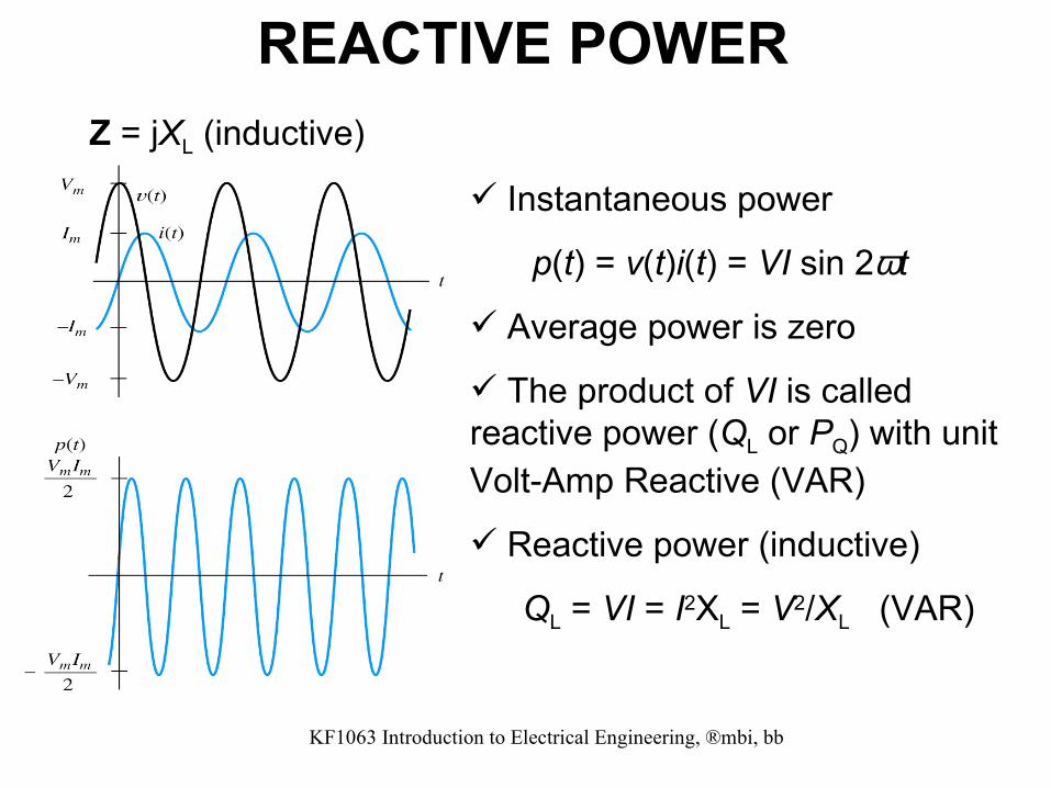
Z = jXL (inductive)
REACTIVE POWER
Instantaneous power
p(t) = v(t)i(t) = VI sin 2ωt
Average power is zero
The product of VI is called reactive power (QL or PQ) with unit Volt-Amp Reactive (VAR)
Reactive power (inductive)
QL = VI = I2XL = V2/XL (VAR)

KF1063 Introduction to Electrical Engineering, ®mbi, bb
Z = – jXC (capacitive)
KUASA REGANGAN
Reactive power (capacitive)
QC = VI = I2XC = V2/XC (VAR)
Note:
To distinguish between inductive reactive power (QL) and capacitive reactive power (QC), we use two different signs (+ or –) depending on our reference (i or v), for example jQL and – jQC or otherwise.

KF1063 Introduction to Electrical Engineering, ®mbi, bb
ACTIVE/REACTIVE POWER - Example
• I = 100 V/25 Ω = 4 A, P = VI = (100 V)(4 A) = 400 W, Q = 0 VAR
• I = 100 V/20 Ω = 5 A, P = 0, QL = VI = (100 V)(5 A) = 500 VAR (inductive)
• I = 100 V/40 Ω = 2.5 A, P = 0, QC = VI = (100 V)(2.5) = 250 VAR (capacitive)
= – 250 VAR
Note: use the magnitude of I and V

KF1063 Introduction to Electrical Engineering, ®mbi, bb
Determine the total PT and QT for the circuit. Sketch the series equivalent circuit.
R = PT/I2 = 1200/202 = 3 Ω
Xeq = XL = QT/I2 = 1600/202 = 4 Ω
ACTIVE/REACTIVE POWER - Example

KF1063 Introduction to Electrical Engineering, ®mbi, bb
For load consisting of series resistance and reactance, Z = R ± jX = Z /±θ , the power produced is called Apparent Power or Complex Power), S or PS with unit Volt-Amp (VA)
APPARENT POWER
S = VI
S = VI
θ positive, inductive load θ negative, capacitive load
S = VI (VA) P = VI kos θ = I2R = VR
2/R (W) = S kos θ (W)Q = VI sin θ = I2X = Vx
2/X (VAR) = S sin θS = √(P2 + Q2) = VI*
V/0°
Power Triangle
S = P + jQL S = P – jQC

KF1063 Introduction to Electrical Engineering, ®mbi, bb
POWER TRIANGLE - Example
Sketch the power triangle.

KF1063 Introduction to Electrical Engineering, ®mbi, bb
S (Z) Q (X) θ P (R)
POWER FACTOR Power factor, p.f. = cos θ = P/S = R/Z p.f. depends on the load type:
Purely resistive load, R , p.f. = 1 Inductive load, RL, p.f. <1 (lagging) and Capacitive load, RC, p.f. < 1 (leading)
Most of the loads are inductive (lagging p.f.) and must be corrected until p.f. approximately become unity (p.f. = 1) using capacitor.

KF1063 Introduction to Electrical Engineering, ®mbi, bb
Leading p.f. (final) = cos θJ; QJ = P tan θJ
QC = Q – QJ
QC = V2/XC ; XC = 1/ jωC = V2/ QC
R C jX V S QC
Q θ θJ QJ P
POWER FACTOR - Correction

KF1063 Introduction to Electrical Engineering, ®mbi, bb
Figure 7.18, 7.19, 7.20
Given: Vs = 117∠0 V, RL = 50 Ω, jXL = 86.7 Ω ω = 377 rad/s
ZL = 50 + j86.7 = 100∠1.047 Ω
IL = VL/ZL = (117∠0 )/(100∠1.047) = 1.17∠–1.047 A
S = VLIL* = 137 ∠1.047) = 68.4 + j118.5 VA
QC = –118.5 VAR XC = VL2/118.5 = – j115 Ω
C = 1/ωXc = 23.1 µF
Find the complex power for the circuit. Correct the circuit power factor to p.f. = 1 using parallel reactance.
POWER FACTOR - Example

KF1063 Introduction to Electrical Engineering, ®mbi, bb
POWER MEASUREMENT
Wattmeter only reads active power on the load side

KF1063 Introduction to Electrical Engineering, ®mbi, bb
POWER MEASUREMENT - ExampleWhat is the reading of wattmeter, W?
PT = 10 + 40 + 700 = 750 W

KF1063 Introduction to Electrical Engineering, ®mbi, bb
P.F. MEASUREMENT - Example
S = VI = (9.615)(240) = 2.308 kVA
p.f. = 1.5 kW/2.308 kVA = 0.65
Q = 1.754 kVAR
If p.f. = 1 (correction)
Xc = V2/Q then C = 80.761 µF
What happen if C = 80 µF?