Lecture4: Informal guidelines for good relational design Mapping ERD to Relation Ref. Chapter3...
38
Lecture4: Informal guidelines for good relational design Mapping ERD to Relation Ref. Chapter3 Lecture4 1
-
Upload
karen-austin -
Category
Documents
-
view
221 -
download
2
Transcript of Lecture4: Informal guidelines for good relational design Mapping ERD to Relation Ref. Chapter3...

Lecture4:Informal guidelines for good relational design
Mapping ERD to Relation
Ref. Chapter3
Lect
ure4
1

Outlines
• Guideline 1: • Semantics of the Relation Attributes
• Guideline 2: • insertion, deletion and update anomalies
• Guideline 3:• Null Values in Tuples
• Guideline 4:• primary key
• Guideline 5: • Avoid Data redundancy
• Mapping ERD to Relations

The Process of Database Design
Lect
ure4
Real World Domain
Conceptual model (ERD)
Relational Data Model
Create schema
(DDL)
Load Data(DML)
3

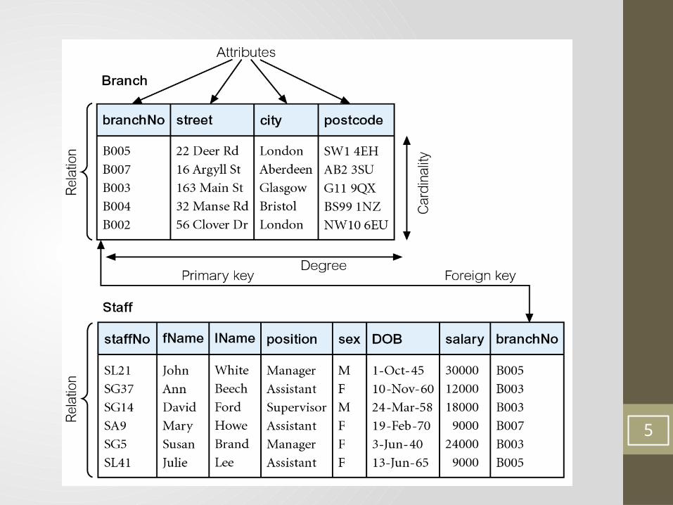
Relational Model Terminology
• A relation is a table with columns and rows.• Attribute is a named column of a relation.• Tuple is a row of a relation.
• Alternative Terminology for Relational Model:
4
5

Lect
ure4
GUIDELINE 1: Semantics of the Relation Attributes and tuples
• Design a schema that can be explained easily relation by relation.
• Each cell of the relation should contains exactly single value
• Each Attribute has a distinct name• Only foreign keys should be used to refer to other
entities• Each tuple is distinct. There are no duplicate tuples • The order of attributes and tuples have no significance.
6

Lect
ure4
GUIDELINE 2: insertion, deletion and update anomalies
• Design a schema that does not suffer from the insertion, deletion and update anomalies.
• Attributes of different entities (EMPLOYEEs, DEPARTMENTs, PROJECTs) should not be mixed in the same relation
• ExampleConsider the relation:EMP_PROJ ( Emp#, Proj#, Ename, Pname, No_hours)
1. Update Anomaly: Changing the name of project number
P1 from “Billing” to “Customer-Accounting” may cause this update to be made for all 100 employees working on project P1.
7

Lect
ure4
2. Insert Anomaly: Cannot insert a project unless an employee is assigned to . Inversely - Cannot insert an employee unless an he/she is
assigned to a project. 3. Delete Anomaly: When a project is deleted, it will result in deleting all the employees who work on that project. Alternately, if an employee is the sole employee on a project, deleting that employee would result in deleting the corresponding project.
Example of an anomaly
8

EXAMPLE OF AN UPDATE ANOMALY
Tbl_Staff_Branch
Tbl_Staff Tbl_Branch

Lect
ure4
• Relations should be designed such that their tuples will have as few NULL values as possible
• Attributes that are NULL frequently could be placed in separate relations (with the primary key)
• NULL values:
• Unknown value: a particular person has a date of birth but it is unknown, so it is represented by NULL in the database.
• Unavailable value: a person has a home phone but does not want it to be listed, so it is represented as NULL in the database.
• Not applicable attribute: an attribute College Degree would be NULL for a person who has no college degrees.
GUIDELINE 3: Null Values in Tuples
10

Lect
ure4
1. The candidate key must be unique within its domain.2. The candidate key cannot hold NULL values (NULL is not
zero. Zero is a number. NULL is 'nonexistent value').3. The candidate key can never change. It must hold the same
value for a given occurrence of an entity for the lifetime of that entity.
GUIDELINE 4: Candidate key
11

Lect
ure4
• Data redundancy is a term used about databases and means simply that some data fields appear more than once in the database.
• Disadvantages :1. weak maintaining of the database2. waste memory
GUIDELINE 5: Avoid Data redundancy
12

Lect
ure4
13

Derive relations for logical data model
• To implement the database in relational DBMS, ERD must be translated to tables 1. Specify the name of the relation.2. A list of the relation’s simple attributes enclosed in brackets.3. Identify the primary key and foreign key(s) of the relation.4. Specify the identification of a foreign key, the relation
containing the referenced
• For example: • Staff (staffNo, fName, lName, position, sex, DOB)• Client (clientNo, fName, lName, telNo, prefType, maxRent,
staffNo) Foreign Key staffNo references Staff(staffNo)14

Lect
ure4
1- Mapping strong entity types
• A (strong) entity set reduces to a table with the same attributes and PK.
• If composite attributes exist, only their component simple attributes are needed.
• Derived attributes are usually omitted.
15
Name
FName MName LName
Employee
EmpNo
Employee ( EmpNo, Fname, Mname, Lname )

Lect
ure4
• A multivalued attribute M of an entity E is represented by a separate table EM1. Includes the multivalued attribute M in EM2. Includes the PK of E as FK in EM3. The PK of EM is the combination of the PK of E and
the multivalued attribute M.
EM ( M , EPK)FKs : EPK references E (EPK)
2- mapping Multi_valued Attributes
16

Example of Multi-valued Attributes
• Branch( brachNo, street, city, postCode)• BrachTel (telNo, brachNo) FK: brachNo references Branch(branchNo)
Branch
BranchNo street
city
postCode
telNo

Lect
ure4
• A weak entity set becomes a table that includes its key and the primary key of the owner entity as FK .
• The combination of the two keys form the PK of the weak entity.Example:
Employee has Dependents
Employee ( EmpNo, Lname)Dependents(empNo, depName, DepAge)FK : empNo referneces Employee (EmpNo)
3- Mapping Weak Entities
18
1 M
empNo DepNameLname DepAge

Lect
ure4
4- mapping Binary Relationships
1. Many-to-many binary relationship setcreate a new relation with columns for the PKs of the two
participating entity sets, and attributes of the relationship.The PK of the new relatoin consists of the PKs of the two entities.The PKs of the two entities also serve as foreign keys referencing
the entities.
19
Student (stNo, stName)Subject (scode, sName)Enroll (stNo, scode, date)FKs: stNO reference Student(stNo) scode reference Subject(sCode)
SUBJECTSTUDENT enroll
M N
date sNamesCodestNostName

Lect
ure4
4- mapping Binary Relationships
2. One-to-many binary relationship sets Instead of using a separate table for the relationship, just modify the tables for the two entities:
add the PK of the one side to the many side. It also serves as a FK of the many side.
Add the attributes of the relationship to the many-side.
20
staffDepartment Has1 N
year sNamesCodeDeptNoDeptName
Department (DeptNo, DeptName)
Staff (scode, sName , DeptNo , year)
FKs: DeptNO references Department(DeptNo)

Lect
ure4
4- mapping Binary Relationships
3. One-to-one relationship sets
• mandatory participation on both sides• add the PK attributes of one side, and attributes of the relationship,
to the other side.
• mandatory on one side• add the PK attributes of the optional side, and attributes of the
relationship, to the mandatory side.
• Optional on both sides• choose one side and add its PK, and attributes of the relationship, to
the other side. 21
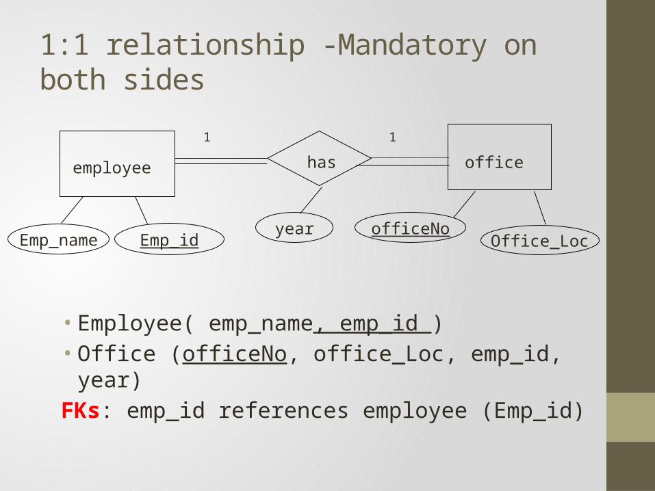
1:1 relationship -Mandatory on both sides
• Employee( emp_name, emp_id )• Office (officeNo, office_Loc, emp_id, year)FKs: emp_id references employee (Emp_id)
employee office
1 1
has
Emp_nameofficeNo
Emp_id Office_Locyear

1:1 relationship - Mandatory on one sides
• Employee( emp_name, emp_id )• Spouse(spouse_id, spouse_name, emp_id, year)FKs: emp_id references employee (Emp_id)
employee spouse
1 1
has
Emp_nameSpouse_id
Emp_id Spoude_nameyear

1:1 relationship - Optional on both sides
• Employee( emp_name, emp_id )• Car (Car_No, Car_name, emp_id, year)FKs: emp_id reference employee (Emp_id)
employee Car
1 1
use
Emp_nameCar_No
Emp_id Car_nameyear

Lect
ure4
• Follow rules for 1:1 binary relationship. • single relation with two copies of the primary key (one needs to
be renamed), plus attributes of the relationship.
5 – Mapping Unary Relationships
25
staff supervise
N
1
staffNo
staffname
Staff ( staffNo, staffname, supervisorstaffNo)

Lect
ure4
• Create a relation R to represent the relationship• Include the PK of the participating entities E1,E2.. En as FKs in R.• The combination of all FKs form the PK of R.• Add the relationship attributes to R
6 – Mapping n-ary Relationships
26
Supplier (Sname) Project (projname) Part (PartNo)Supply (Sname, PartNo, ProjName, Quantity)fKs : Sname references Supplier(Sname)
PartNo references Part (PartNo)ProjName references Project (ProjName)

Lect
ure4
27

Lect
ure4
28
EER Relational Model

Lect
ure4
Mandatory / Overlap
• Suppose specialization with subclasses (S1, S2, .., Sm) & a
superclass C.
• Create a relation L to represent C with PK & attributes.
• Include the unshared attributes for each subclass Si, 1 i m.
• Add discriminator in L to distinguish the type of each tuple.
29

Lect
ure4
Mandatory / Overlap
30
• SECRETARY • TECHNICIAN • ENGINEER
• EMPLOYEE
• EmpNo
• Fname
• LName
• DOB
• Salary
• o
• Typing• Speed • EngType
• TGrade
EMPLOYEE( EmpNo, Fname, Lname, DOB, Salary,TypingSpeed,TGrade, EngType, Secretary Flag, Technician Flag, Engineer Flag )

Lect
ure4
Mandatory / Disjoint
• Suppose specialization with subclasses (S1, S2, .., Sm) & a
superclass C.
• Create a relation Li, 1 i m, to represent each combination of
super/subclass.
31

Lect
ure4
Mandatory / Disjoint
32
• SECRETARY • TECHNICIAN • ENGINEER
• EMPLOYEE
• EmpNo
• Fname
• LName
• DOB
• Salary
• d
• Typing• Speed • EngType
• TGrade
SECRETARY(EmpNo, Fname, Lname, DOB, Salary,TypingSpeed)
TECHNICIAN(EmpNo, Fname, Lname, DOB, Salary,Tgrade)
ENGINEER(EmpNo, Fname, Lname, DOB, Salary, EngType)

Lect
ure4
Optional / Overlap• Suppose specialization with subclasses (S1, S2, .., Sm) & a
superclass C.
• Create a relation L1 to represent C with PK & attributes.
• Create a relation L2 to represent all subclasses Si, 1 i m.
• Add discriminator in L2 to distinguish the type of each tuple.
33

Lect
ure4
Optional / Overlap
34
SECRETARY TECHNICIAN ENGINEER
EMPLOYEE
EmpNo
Fname
LName
DOB
Salary
o
TypingSpeed EngType
TGrade
EMPLOYEE(EmpNo, Fname, Lname, DOB, Salary)
SUB-EMP(EmpNo, TypingSpeed,TGrade, EngType,
Secretary Flag, Technician Flag, Engineer Flag)

Lect
ure4
Optional / Disjoint
• Suppose specialization with subclasses (S1, S2, .., Sm) & a
superclass C.
• Create a relation L to represent C with PK & attributes.
• Create a relation Li to represent each subclass Si, 1 i m,
and include the PK.
35

Lect
ure4
Optional / Disjoint
36
• SECRETARY • TECHNICIAN • ENGINEER
• EMPLOYEE
• EmpNo
• Fname
• LName
• DOB
• Salary
• d
• Typing• Speed • EngType
• TGrade
EMPLOYEE(EmpNo, Fname, Lname, DOB, Salary)
SECRETARY(EmpNo, TypingSpeed)
TECHNICIAN(EmpNo, Tgrade)
ENGINEER(EmoNo, EngType)

Lect
ure4
37

References
• “Database Systems: A Practical Approach to Design, Implementation and Management.” Thomas Connolly, Carolyn Begg. 5th Edition, Addison-Wesley, 2009.
Lect
ure4
38