Lecture4
25
Lecture 4 8086 Instruction Set 1 Zelalem Birhanu, AAiT
-
Upload
misgina2005 -
Category
Documents
-
view
51 -
download
0
Transcript of Lecture4

Lecture 4
8086 Instruction Set
1Zelalem Birhanu, AAiT

In this lecture
• Introduction
• 8086 Instruction Types
• 8086 Addressing Modes
2Zelalem Birhanu, AAiT

Introduction – recap
• There are three language levels that can be used to write a program for a microcomputer
Machine language
Assembly Language
High-Level Language
3Zelalem Birhanu, AAiT
Introduction – recap…cntd
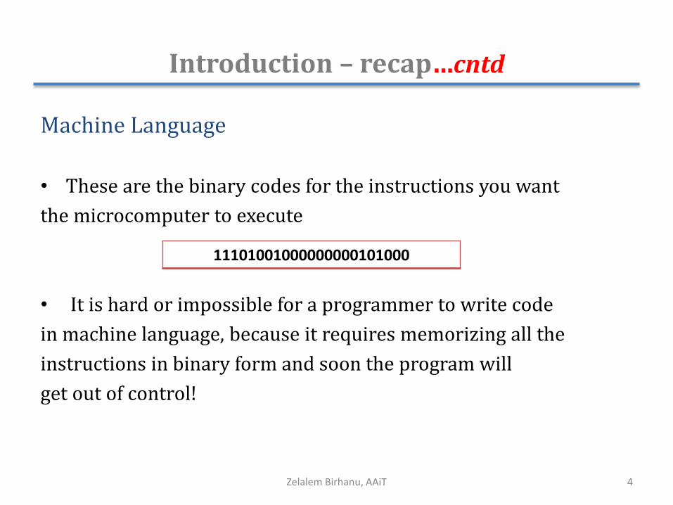
Machine Language
• These are the binary codes for the instructions you want
the microcomputer to execute
• It is hard or impossible for a programmer to write code
in machine language, because it requires memorizing all the
instructions in binary form and soon the program will
get out of control!
4Zelalem Birhanu, AAiT
11101001000000000101000

Introduction – recap…cntd
Assembly Language
• Uses two, three, or four letter mnemonics to represent each instruction type
• The letters in an assembly language mnemonic are usually initials or a short form of the English word(s) for the operation performed by the instruction
e.g., SUB for subtract , XOR for Exclusive OR , etc
• Assembly language program has to be translated to
machine language so that it can be loaded into memory
and run – This is done by the assembler5Zelalem Birhanu, AAiT

Introduction – recap…cntd
High-Level Languages
• These languages use program statements which are even more English-like than those of assembly language
e.g. BASIC, C, C++, Java, ...
• Each high-level statement may represent many machine code instructions
• An interpreter (compiler) program is used to translate higher-level language statements to machine codes, which can be loaded into memory and executed.
6Zelalem Birhanu, AAiT

Introduction – recap…cntd
• Elements of an instruction
• 8086 has variable-length instructions (8 bits to 40 bits)
7Zelalem Birhanu, AAiT
Operation Code (Opcode)
Addresses (operands)

8086 Instruction Types
• The 8086 instructions can be grouped in to six categories
Data transfer instructions
Arithmetic instructions
Bit manipulation instructions
String manipulation instructions
Control transfer instructions
Processor control instructions
8Zelalem Birhanu, AAiT

Data Transfer Instructions
• Used to transfer data from source operand to destination operandMemory to register e.g. MOV AX, [0005h] (AX←[0005h])
Register to memory e.g. PUSH AL
Immediate to memory/register e.g. MOV AH, 09h
I/O device to register e.g. IN AX, 4
Register to I/O device e.g. OUT AL, 2
• All the store, move, load, exchange, input and output instructions belong to this category
MOV , PUSH, POP , XCHG, XLAT, IN, OUT, LEA, PUSHF, POPF
9Zelalem Birhanu, AAiT

Arithmetic instructions
• Perform arithmetic operations Addition e.g. ADD, ADC, INC, AAA,
Subtraction e.g. SUB, SBB, DEC, CMP
Multiplication e.g. MUL, IMUL
Division e.g. DIV, IDIV
e.g. ADD AL, 5 (AL←AL+5)
MUL BL (AX ←AL*BL)
MUL BX (DX:AX ←AX*BX)
10Zelalem Birhanu, AAiT

Bit Manipulation Instructions
• Logical instructionsNOT, AND, OR, XOR
• Shift instructionsSHL, SHR, SAL, SAR
• Rotate instructionsROL, ROR, RCL, RCR
e.g. MOV AL, 1Ch (AL←1Ch (00011100b))
ROR AL, 1 (rotate AL one bit to the right) (AL = 00001110b)
11Zelalem Birhanu, AAiT
Byte/WordCF
Byte/WordCF
RCL
RCR

String Manipulation Instructions
• A string is a series of bytes or a series of words in sequential memory locations. It often consists of ASCII character codes
e.g. LODSB – Load byte at DS: [SI] into AL. Update SI
STOSW – Store word in AX into ES:[DI]. Update DI
CMPSB – Compare bytes: ES:[DI] from DS:[SI]
12Zelalem Birhanu, AAiT

Control Transfer Instructions
• These instructions are used to tell the processor to start fetching instructions from some new address, rather than continuing in sequenceUnconditional transfer instructions e.g. CALL, RET, JMP
Conditional transfer instructions e.g. JE, JG, JGE, JL, JLE, JZ
Iteration control instructions e.g. LOOP, LOOPE, JCXZ
Interrupt instructions e.g. INT, IRET
e.g. SUB AX, 32
JZ label
…
label:
MOV BX, 10
13Zelalem Birhanu, AAiT
AX=AX-32;If(AX==0)
{BX=10;
}

Processor Control Instructions
• Set/clear flags, control the operation of the processor
Flag instructions
e.g. STC – set carry flag
External hardware synchronization instructions
e.g. WAIT - Do nothing until signal on the TEST pin is low
No operation instructions e.g. NOP
14Zelalem Birhanu, AAiT

Addressing Modes
• Describe the types of operands and the way they are accessed for executing an instruction
• 8086 addressing modes: Immediate
Direct
Register
Register Indirect
Indexed
Register Relative
Based Indexed
Relative Based Indexed
15Zelalem Birhanu, AAiT

Immediate Addressing
• Immediate data is a part of instruction, and appears in
the form of successive byte(s)
e.g. MOV AX, 0005H (AX←0005H)
Here, 0005H is the immediate data. The immediate
data may be 8-bit or 16-bit in size.
16Zelalem Birhanu, AAiT

Direct Addressing
• In the direct addressing mode, a 16-bit memory address (offset) is directly specified in the instruction
e.g. MOV AX, [5000H ] (AX←[DS:5000H])
Here, data resides in a memory location in the data
segment, whose effective address may be computed
using 5000H as the offset address and content of DS
as segment address.
17Zelalem Birhanu, AAiT

Register Addressing
• In register addressing mode, the data is stored in a register and it is referred using the particular register
• All the registers, except IP, may be used in this mode
e.g. MOV AX, BX (AX←BX)
Here, data is transferred from register BX to register AX
18Zelalem Birhanu, AAiT
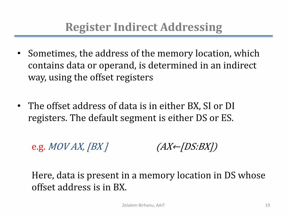
Register Indirect Addressing
• Sometimes, the address of the memory location, which contains data or operand, is determined in an indirect way, using the offset registers
• The offset address of data is in either BX, SI or DI registers. The default segment is either DS or ES.
e.g. MOV AX, [BX ] (AX←[DS:BX])
Here, data is present in a memory location in DS whose offset address is in BX.
19Zelalem Birhanu, AAiT

Indexed Addressing
• Offset of the operand is stored in one of the index registers (SI and DI). DS and ES are the default segments for SI and DI respectively
• This mode is a special case of register indirect addressing mode
e.g. MOV AX, [SI ] (AX←[DS:SI])
Here, data is present in a memory location in DS whose offset address is in SI.
20Zelalem Birhanu, AAiT

Register Relative Addressing
• The data is available at an effective address formed by adding an 8-bit or 16-bit displacement with the content of any one of the registers BX, BP, SI and DI in the default segment (DS or ES)
e.g. MOV AX, 50H[BX ] (AX←[DS:BX+50H])
21Zelalem Birhanu, AAiT

Based Indexed Addressing
• The effective address of data is formed by adding content of a base register (BX or BP) to the content of an index register (SI or DI)
e.g. MOV AX, [BX ][SI] (AX←[DS:BX+SI])
22Zelalem Birhanu, AAiT

Relative Based Indexed Addressing
• The effective address is formed by adding an 8 or 16-bit displacement with the sum of contents of any one of the base registers (BX or BP) and any one of the index registers (SI or DI), in a default segment
e.g. MOV AX, 50H[BX ][SI] (AX←[DS:BX+SI+50])
23Zelalem Birhanu, AAiT

Emu8086
• Assembler (flat assembler)+ emulator (MS-DOS system)
24Zelalem Birhanu, AAiT

More Readings
1. Dr. Manoj’s Handouts, Chapter 2
2. 8086 datasheet
3. emu8086 documentation
25Zelalem Birhanu, AAiT