LECTURE NOTES ON CLOUD COMPUTING computing.pdf · public utility services such as water,...
222
LECTURE NOTES ON CLOUD COMPUTING
Transcript of LECTURE NOTES ON CLOUD COMPUTING computing.pdf · public utility services such as water,...

LECTURE NOTES
ON
CLOUD COMPUTING

Unit-1
INTRODUCTION TO CLOUD COMPUTING
CLOUD COMPUTING IN A NUTSHELL
Computing itself, to be considered fully virtualized, must allow computers to
be built from distributed components such as processing, storage, data, and
software resources.
Technologies such as cluster, grid, and now, cloud computing, have all
aimed at allowing access to large amounts of computing power in a fully
virtualized manner, by aggregating resources and offering a single system
view. Utility computing describes a business model for on-demand delivery of
computing power; consumers pay providers based on usage (“payas-you-
go”), similar to the way in which we currently obtain services from traditional
public utility services such as water, electricity, gas, and telephony.
Cloud computing has been coined as an umbrella term to describe a
category of sophisticated on-demand computing services initially offered by
commercial providers, such as Amazon, Google, and Microsoft. It denotes a
model on which a computing infrastructure is viewed as a “cloud,” from which
businesses and individuals access applications from anywhere in the world on
demand . The main principle behind this model is offering computing, storage,
and software “as a service.”
Many practitioners in the commercial and academic spheres have attempted
to define exactly what “cloud computing” is and what unique characteristics it
presents. Buyya et al. have defined it as follows: “Cloud is a parallel and
distributed computing system consisting of a collection of inter-connected
and virtualised computers that are dynamically provisioned and presented as one
or more unified computing resources based on service-level agreements (SLA)
established through negotiation between the service provider and consumers.”

Vaquero et al. have stated “clouds are a large pool of easily usable and
accessible virtualized resources (such as hardware, development platforms
and/or services). These resources can be dynamically reconfigured to adjust
to a variable load (scale), allowing also for an optimum resource utilization.
This pool of resources is typically exploited by a pay-per-use model in which
guarantees are offered by the Infrastructure Provider by means of customized
Service Level Agreements.”
A recent McKinsey and Co. report claims that “Clouds are
hardwarebased services offering compute, network, and storage capacity
where: Hardware management is highly abstracted from the buyer, buyers
incur infrastructure costs as variable OPEX, and infrastructure capacity is
highly elastic.”
A report from the University of California Berkeley summarized the key
characteristics of cloud computing as: “(1) the illusion of infinite computing
resources; (2) the elimination of an up-front commitment by cloud users; and
(3) the ability to pay for use ... as needed .. .”
The National Institute of Standards and Technology (NIST) characterizes
cloud computing as “... a pay-per-use model for enabling available,
convenient, on-demand network access to a shared pool of configurable
computing resources (e.g. networks, servers, storage, applications, services)
that can be rapidly provisioned and released with minimal management effort
or service provider interaction.”
In a more generic definition, Armbrust et al. define cloud as the “data
center hardware and software that provide services.” Similarly, Sotomayor
et al. point out that “cloud” is more often used to refer to the IT infrastructure
deployed on an Infrastructure as a Service provider data center. While there are
countless other definitions, there seems to be common characteristics between
the most notable ones listed above, which a cloud should have: (i) pay-per-use
(no ongoing commitment, utility prices); (ii) elastic capacity and the illusion of
infinite resources; (iii) self-service interface; and (iv) resources that are
abstracted or virtualised.
ROOTS OF CLOUD COMPUTING
We can track the roots of clouds computing by observing the advancement of
several technologies, especially in hardware (virtualization, multi-core chips),
Internet technologies (Web services, service-oriented architectures, Web 2.0),
distributed computing (clusters, grids), and systems management (autonomic
computing, data center automation). Figure 1.1 shows the convergence of
technology fields that significantly advanced and contributed to the advent
of cloud computing.
Some of these technologies have been tagged as hype in their early stages
of development; however, they later received significant attention from
academia and were sanctioned by major industry players. Consequently, a
specification and standardization process followed, leading to maturity and
wide adoption. The emergence of cloud computing itself is closely linked to
the maturity of such technologies. We present a closer look at the technol ogies
that form the base of cloud computing, with the aim of providing a clearer
picture of the cloud ecosystem as a whole.

From Mainframes to Clouds
We are currently experiencing a switch in the IT world, from in-house
generated computing power into utility-supplied computing resources delivered
over the Internet as Web services. This trend is similar to what occurred about a
century ago when factories, which used to generate their own electric power,
realized that it is was cheaper just plugging their machines into the newly
formed electric power grid .
Computing delivered as a utility can be defined as “on demand delivery of
infrastructure, applications, and business processes in a security-rich, shared,
scalable, and based computer environment over the Internet for a fee” .

Hardware
Systems Management
FIGURE 1.1. Convergence of various advances leading to the advent of
cloud computing.
This model brings benefits to both consumers and providers of IT services.
Consumers can attain reduction on IT-related costs by choosing to obtain
cheaper services from external providers as opposed to heavily investing on IT
infrastructure and personnel hiring. The “on-demand” component of this
model allows consumers to adapt their IT usage to rapidly increasing or
unpredictable computing needs.
Providers of IT services achieve better operational costs; hardware and
software infrastructures are built to provide multiple solutions and serve many
users, thus increasing efficiency and ultimately leading to faster return on
investment (ROI) as well as lower total cost of ownership (TCO).
The mainframe era collapsed with the advent of fast and inexpensive
microprocessors and IT data centers moved to collections of commodity servers.
The advent of increasingly fast fiber-optics networks has relit the fire, and
new technologies for enabling sharing of computing power over great distances
have appeared.
SOA, Web Services, Web 2.0, and Mashups
• Web Service
• applications running on different messaging product platforms
• enabling information from one application to be made available to
others
• enabling internal applications to be made available over the Internet
• SOA
• address requirements of loosely coupled, standards-based, and
Hardware Virtualization Multi-core chips
Utility & Grid
Computing
Cloud Computing
SOA Web 2.0
Web Services
Mashups
Autonomic Computing Data Center Automation
Intern
et Tech
nolo
gies D
istr
ibute
d C
om
pu
ting

protocol-independent distributed computing
• WS ,HTTP, XML
• Common mechanism for delivering service
• applications is a collection of services that together perform
complex business logic
• Building block in IaaS
• User authentication, payroll management, calender
Grid Computing
Grid computing enables aggregation of distributed resources and transparently
access to them. Most production grids such as TeraGrid and EGEE seek to
share compute and storage resources distributed across different administrative
domains, with their main focus being speeding up a broad range of scientific
applications, such as climate modeling, drug design, and protein analysis.
Globus Toolkit is a middleware that implements several standard Grid
services and over the years has aided the deployment of several service-oriented
Grid infrastructures and applications. An ecosystem of tools is available to
interact with service grids, including grid brokers, which facilitate user
interaction with multiple middleware and implement policies to meet QoS
needs.
Virtualization technology has been identified as the perfect fit to issues that
have caused frustration when using grids, such as hosting many dissimilar
software applications on a single physical platform. In this direction, some
research projects.
Utility Computing
In utility computing environments, users assign a “utility” value to their jobs,
where utility is a fixed or time-varying valuation that captures various QoS
constraints (deadline, importance, satisfaction). The valuation is the amount
they are willing to pay a service provider to satisfy their demands. The service
providers then attempt to maximize their own utility, where said utility may
directly correlate with their profit. Providers can choose to prioritize high yield
(i.e., profit per unit of resource) user jobs, leading to a scenario where shared
systems are viewed as a marketplace, where users compete for resources based
on the perceived utility or value of their jobs.
Hardware Virtualization
The idea of virtualizing a computer system’s resources, including processors,
memory, and I/O devices, has been well established for decades, aiming at
improving sharing and utilization of computer systems . Hardware
virtualization allows running multiple operating systems and software stacks on
a single physical platform. As depicted in Figure 1.2, a software layer, the
virtual machine monitor (VMM), also called a hypervisor, mediates access to
the physical hardware presenting to each guest operating system a virtual
machine (VM), which is a set of virtual platform interfaces .

FIGURE 1.2. A hardware virtualized server hosting three virtual machines, each one
running distinct operating system and user level software stack.
Virtual Machine 1
User software
Email Server
Virtual Machine 2
User software
Facebook App
Virtual Machine N
User software
App A App X
Data base
Web Server
Java Ruby on
Rails App B App Y
Linux Guest OS
Virtual Machine Monitor (Hypervisor)
Hardware

Workload isolation is achieved since all program instructions are fully
confined inside a VM, which leads to improvements in security. Better
reliability is also achieved because software failures inside one VM do not
affect others . Moreover, better performance control is attained since execution
of one VM should not affect the performance of another VM .
VMWare ESXi. VMware is a pioneer in the virtualization market. Its ecosystem
of tools ranges from server and desktop virtualization to high-level
management tools . ESXi is a VMM from VMWare. It is a bare-metal
hypervisor, meaning that it installs directly on the physical server, whereas
others may require a host operating system.
Xen. The Xen hypervisor started as an open-source project and has served as a
base to other virtualization products, both commercial and open-source.In
addition to an open-source distribution , Xen currently forms the base of
commercial hypervisors of a number of vendors, most notably Citrix
XenServer and Oracle VM.
KVM. The kernel-based virtual machine (KVM) is a Linux virtualization
subsystem. Is has been part of the mainline Linux kernel since version 2.6.20,
thus being natively supported by several distributions. In addition, activities
such as memory management and scheduling are carried out by existing kernel
features, thus making KVM simpler and smaller than hypervisors that take
control of the entire machine .
KVM leverages hardware-assisted virtualization, which improves
performance and allows it to support unmodified guest operating systems ;
currently, it supports several versions of Windows, Linux, and UNIX .
Virtual Appliances and the Open Virtualization Format
An application combined with the environment needed to run it (operating
system, libraries, compilers, databases, application containers, and so forth) is
referred to as a “virtual appliance.” Packaging application environments in the
shape of virtual appliances eases software customization, configuration, and
patching and improves portability. Most commonly, an appliance is shaped as
a VM disk image associated with hardware requirements, and it can be readily
deployed in a hypervisor.
In a multitude of hypervisors, where each one supports a different VM image
format and the formats are incompatible with one another, a great deal of
interoperability issues arises. For instance, Amazon has its Amazon machine
image (AMI) format, made popular on the Amazon EC2 public cloud. Other
formats are used by Citrix XenServer, several Linux distributions that ship with
KVM, Microsoft Hyper-V, and VMware ESX.
OVF’s extensibility has encouraged additions relevant to management of
data centers and clouds. Mathews et al. have devised virtual machine contracts
(VMC) as an extension to OVF. A VMC aids in communicating and managing
the complex expectations that VMs have of their runtime environment and vice
versa.

Autonomic Computing
The increasing complexity of computing systems has motivated research on
autonomic computing, which seeks to improve systems by decreasing human
involvement in their operation. In other words, systems should manage
themselves, with high-level guidance from humans .
In this sense, the concepts of autonomic computing inspire software
technologies for data center automation, which may perform tasks such as:
management of service levels of running applications; management of data
center capacity; proactive disaster recovery; and automation of VM
provisioning .
LAYERS AND TYPES OF CLOUDS
Cloud computing services are divided into three classes, according to the
abstraction level of the capability provided and the service model of providers,
namely: (1) Infrastructure as a Service, (2) Platform as a Service, and (3) Software
as a Service . Figure 1.3 depicts the layered organization of the cloud stack
from physical infrastructure to applications.
These abstraction levels can also be viewed as a layered architecture where
services of a higher layer can be composed from services of the underlying
layer.
Infrastructure as a Service
Offering virtualized resources (computation, storage, and communication) on
demand is known as Infrastructure as a Service (IaaS) . A cloud infrastructure
FIGURE 1.3. The cloud computing stack.
Service Class
Main Access & Management Tool Service content
Cloud Applications
Web Browser
SaaS
Social networks, Office suites, CRM, Video processing
Cloud Platform
PaaS
Cloud Development
Environment Programming languages, Frameworks, Mashups editors, Structured data
Cloud Infrastructure
IaaS
Virtual Infrastructure
Manager 17
Compute Servers, Data Storage, Firewall, Load Balancer

enables on-demand provisioning of servers running several choices of operating
systems and a customized software stack. Infrastructure services are considered
to be the bottom layer of cloud computing systems .
Platform as a Service
In addition to infrastructure-oriented clouds that provide raw computing and
storage services, another approach is to offer a higher level of abstraction to
make a cloud easily programmable, known as Platform as a Service (PaaS)..
Google AppEngine, an example of Platform as a Service, offers a scalable
environment for developing and hosting Web applications, which should
be written in specific programming languages such as Python or Java, and use
the services’ own proprietary structured object data store.
Software as a Service
Applications reside on the top of the cloud stack. Services provided by this
layer can be accessed by end users through Web portals. Therefore, consumers
are increasingly shifting from locally installed computer programs to on-line
software services that offer the same functionally. Traditional desktop
applications such as word processing and spreadsheet can now be accessed as a
service in the Web.
Deployment Models
Although cloud computing has emerged mainly from the appearance of public
computing utilities. In this sense, regardless of its service class, a cloud can be
classified as public, private, community, or hybrid based on model of
deployment as shown in Figure 1.4.
Mixed usage of private and public
Clouds: Leasing public cloud services
when private cloud capacity is insufficient
Cloud computing model run
within a company’s
own Data Center/
infrastructure for
internal and/or
partners use.
3rd party, multi-tenant Cloud
infrastructure & services:
* available on subscription basis (pay as you go)
Public/Internet
Clouds
Private/Enterprise Clouds
Hybrid/Mixed Clouds

FIGURE 1.4. Types of clouds based on deployment models.

Armbrust propose definitions for public cloud as a “cloud made available in
a pay-as-you-go manner to the general public” and private cloud as “internal
data center of a business or other organization, not made available to the
general public.”
A community cloud is “shared by several organizations and supports a
specific community that has shared concerns (e.g., mission, security
requirements, policy, and compliance considerations) .”
A hybrid cloud takes shape when a private cloud is supplemented with
computing capacity from public clouds . The approach of temporarily renting
capacity to handle spikes in load is known as “cloud-bursting” .
DESIRED FEATURES OF A CLOUD
Certain features of a cloud are essential to enable services that truly represent
the cloud computing model and satisfy expectations of consumers, and cloud
offerings must be (i) self-service, (ii) per-usage metered and billed, (iii) elastic,
and (iv) customizable.
Self-Service
Consumers of cloud computing services expect on-demand, nearly instant
access to resources. To support this expectation, clouds must allow self-service
access so that customers can request, customize, pay, and use services without
intervention of human operators .
Per-Usage Metering and Billing
Cloud computing eliminates up-front commitment by users, allowing them to
request and use only the necessary amount. Services must be priced on a
shortterm basis (e.g., by the hour), allowing users to release (and not pay for)
resources as soon as they are not needed.
Elasticity
Cloud computing gives the illusion of infinite computing resources available on
demand . Therefore users expect clouds to rapidly provide resources in any
quantity at any time. In particular, it is expected that the additional resources
can be (a) provisioned, possibly automatically, when an application load
increases and (b) released when load decreases (scale up and down) .
Customization
In a multi-tenant cloud a great disparity between user needs is often the case.
Thus, resources rented from the cloud must be highly customizable. In the case
of infrastructure services, customization means allowing users to deploy
specialized virtual appliances and to be given privileged (root) access to the
virtual servers. Other service classes (PaaS and SaaS) offer less flexibility and
are not suitable for general-purpose computing , but still are expected to
provide a certain level of customization.

CLOUD INFRASTRUCTURE MANAGEMENT
A key challenge IaaS providers face when building a cloud infrastructure is
managing physical and virtual resources, namely servers, storage, and
networks, in a holistic fashion . The orchestration of resources must be
performed in a way to rapidly and dynamically provision resources to
applications .
The availability of a remote cloud-like interface and the ability of managing
many users and their permissions are the primary features that would
distinguish “cloud toolkits” from “VIMs.” However, in this chapter, we place
both categories of tools under the same group (of the VIMs) and, when
applicable, we highlight the availability of a remote interface as a feature.
Virtually all VIMs we investigated present a set of basic features related to
managing the life cycle of VMs, including networking groups of VMs together
and setting up virtual disks for VMs. These basic features pretty much define
whether a tool can be used in practical cloud deployments or not. On the other
hand, only a handful of software present advanced features (e.g., high
availability) which allow them to be used in large-scale production clouds.
Features
We now present a list of both basic and advanced features that are usually
available in VIMs.
Virtualization Support. The multi-tenancy aspect of clouds requires multiple
customers with disparate requirements to be served by a single hardware
infrastructure.
Self-Service, On-Demand Resource Provisioning. Self-service access to
resources has been perceived as one the most attractive features of clouds. This
feature enables users to directly obtain services from clouds.
Multiple Backend Hypervisors. Different virtualization models and tools offer
different benefits, drawbacks, and limitations. Thus, some VI managers
provide a uniform management layer regardless of the virtualization
technology used.
Storage Virtualization. Virtualizing storage means abstracting logical storage
from physical storage. By consolidating all available storage devices in a data
center, it allows creating virtual disks independent from device and location.
In the VI management sphere, storage virtualization support is often
restricted to commercial products of companies such as VMWare and Citrix.
Other products feature ways of pooling and managing storage devices, but
administrators are still aware of each individual device.
Interface to Public Clouds. Researchers have perceived that extending the

capacity of a local in-house computing infrastructure by borrowing resources
from public clouds is advantageous. In this fashion, institutions can make good
use of their available resources and, in case of spikes in demand, extra load can
be offloaded to rented resources .
Virtual Networking. Virtual networks allow creating an isolated network on
top of a physical infrastructure independently from physical topology and
locations. A virtual LAN (VLAN) allows isolating traffic that shares a
switched network, allowing VMs to be grouped into the same broadcast
domain.
Dynamic Resource Allocation. Increased awareness of energy consumption in
data centers has encouraged the practice of dynamic consolidating VMs in a
fewer number of servers. In cloud infrastructures, where applications
have variable and dynamic needs, capacity management and demand
prediction are especially complicated. This fact triggers the need for dynamic
resource allocation aiming at obtaining a timely match of supply and
demand.
Virtual Clusters. Several VI managers can holistically manage groups of VMs.
This feature is useful for provisioning computing virtual clusters on demand,
and interconnected VMs for multi-tier Internet applications.
Reservation and Negotiation Mechanism. When users request computational
resources to available at a specific time, requests are termed advance
reservations (AR), in contrast to best-effort requests, when users request
resources whenever available .
Additionally, leases may be negotiated and renegotiated, allowing provider
and consumer to modify a lease or present counter proposals until an
agreement is reached.
High Availability and Data Recovery. The high availability (HA) feature of VI
managers aims at minimizing application downtime and preventing business
disruption.
For mission critical applications, when a failover solution involving
restarting VMs does not suffice, additional levels of fault tolerance that rely on
redundancy of VMs are implemented.
Data backup in clouds should take into account the high data volume
involved in VM management.

Case Studies
In this section, we describe the main features of the most popular VI managers
available. Only the most prominent and distinguishing features of each tool are
discussed in detail. A detailed side-by-side feature comparison of VI managers
is presented in Table 1.1.
Apache VCL. The Virtual Computing Lab [60, 61] project has been incepted in
2004 by researchers at the North Carolina State University as a way to provide
customized environments to computer lab users. The software components that
support NCSU’s initiative have been released as open-source and incorporated
by the Apache Foundation.
AppLogic. AppLogic is a commercial VI manager, the flagship product of
3tera Inc. from California, USA. The company has labeled this product as a
Grid Operating System.
AppLogic provides a fabric to manage clusters of virtualized servers,
focusing on managing multi-tier Web applications. It views an entire
application as a collection of components that must be managed as a single
entity.
In summary, 3tera AppLogic provides the following features: Linux-based
controller; CLI and GUI interfaces; Xen backend; Global Volume Store (GVS)
storage virtualization; virtual networks; virtual clusters; dynamic resource
allocation; high availability; and data protection.

TABLE 1.1. Feature Comparison of Virtual Infrastructure Managers
License
Installation
Platform of
Controller
Client UI,
API, Language
Bindings
Backend
Hypervisor(s)
Storage
Virtualization
Interface to
Public Cloud
Virtual
Networks
Dynamic Resource
Allocation
Advance
Reservation of
Capacity
High
Availability
Data
Protection
Apache
VCL
Apache v2 Multi-
platform
(Apache/
PHP)
Portal,
XML-RPC
VMware
ESX, ESXi,
Server
No No Yes No Yes No No
AppLogic Proprietary Linux GUI, CLI Xen Global
Volume
Store (GVS)
No Yes Yes No Yes Yes
Citrix Essentials Proprietary Windows GUI, CLI,
Portal,
XML-RPC
XenServer,
Hyper-V
Citrix
Storage
Link
No Yes Yes No Yes Yes
Enomaly ECP GPL v3 Linux Portal, WS Xen No Amazon EC2 Yes No No No No
Eucalyptus BSD Linux EC2 WS, CLI Xen, KVM No EC2 Yes No No No No
Nimbus Apache v2 Linux EC2 WS, Xen, KVM No EC2 Yes Via Yes (via No No
WSRF, CLI integration with
OpenNebula
integration with
OpenNebula)
OpenNEbula Apache v2 Linux XML-RPC,
CLI, Java
Xen, KVM No Amazon EC2,
Elastic Hosts
Yes Yes Yes
(via Haizea)
No No
(Java)
OpenPEX GPL v2 Multiplatform Portal, WS XenServer No No No No Yes No No
oVirt GPL v2 Fedora Linux Portal KVM No No No No No No No
Platform
ISF
Proprietary Linux Portal Hyper-V
XenServer,
VMWare ESX
No EC2, IBM CoD,
HP Enterprise
Services
Yes Yes Yes Unclear Unclear
Platform VMO Proprietary Linux, Portal XenServer No No Yes Yes No Yes No
Windows
VMWare
vSphere
Proprietary Linux,
Windows
CLI, GUI,
Portal, WS
VMware
ESX, ESXi
VMware
vStorage
VMFS
VMware
vCloud partners
Yes VMware
DRM
No Yes Yes

Citrix Essentials. The Citrix Essentials suite is one the most feature complete
VI management software available, focusing on management and automation
of data centers. It is essentially a hypervisor-agnostic solution, currently
supporting Citrix XenServer and Microsoft Hyper-V.
Enomaly ECP. The Enomaly Elastic Computing Platform, in its most complete
edition, offers most features a service provider needs to build an IaaS cloud.
In summary, Enomaly ECP provides the following features: Linux-based
controller; Web portal and Web services (REST) interfaces; Xen back-end;
interface to the Amazon EC2 public cloud; virtual networks; virtual clusters
(ElasticValet).
Eucalyptus. The Eucalyptus framework was one of the first open-source
projects to focus on building IaaS clouds. It has been developed with the intent
of providing an open-source implementation nearly identical in functionality to
Amazon Web Services APIs.
Nimbus3. The Nimbus toolkit is built on top of the Globus framework. Nimbus
provides most features in common with other open-source VI managers, such
as an EC2-compatible front-end API, support to Xen, and a backend interface
to Amazon EC2.
Nimbus’ core was engineered around the Spring framework to be easily
extensible, thus allowing several internal components to be replaced and also
eases the integration with other systems.
In summary, Nimbus provides the following features: Linux-based
controller; EC2-compatible (SOAP) and WSRF interfaces; Xen and KVM
backend and a Pilot program to spawn VMs through an LRM; interface to the
Amazon EC2 public cloud; virtual networks; one-click virtual clusters.
OpenNebula. OpenNebula is one of the most feature-rich open-source VI
managers. It was initially conceived to manage local virtual infrastructure, but
has also included remote interfaces that make it viable to build public clouds.
Altogether, four programming APIs are available: XML-RPC and libvirt for
local interaction; a subset of EC2 (Query) APIs and the OpenNebula Cloud
API (OCA) for public access [7, 65].
(Amazon EC2, ElasticHosts); virtual networks; dynamic resource
allocation; advance reservation of capacity.
OpenPEX. OpenPEX (Open Provisioning and EXecution Environment) was
constructed around the notion of using advance reservations as the primary
method for allocating VM instances.
oVirt. oVirt is an open-source VI manager, sponsored by Red Hat’s Emergent
Technology group. It provides most of the basic features of other VI managers,

including support for managing physical server pools, storage pools, user
accounts, and VMs. All features are accessible through a Web interface.
Platform ISF. Infrastructure Sharing Facility (ISF) is the VI manager offering
from Platform Computing [68]. The company, mainly through its LSF family
of products, has been serving the HPC market for several years.
ISF is built upon Platform’s VM Orchestrator, which, as a standalone
product, aims at speeding up delivery of VMs to end users. It also provides high
availability by restarting VMs when hosts fail and duplicating the VM that
hosts the VMO controller.
VMWare vSphere and vCloud. vSphere is VMware’s suite of tools aimed at
transforming IT infrastructures into private clouds. It distinguishes from other
VI managers as one of the most feature-rich, due to the company’s several
offerings in all levels the architecture.
In the vSphere architecture, servers run on the ESXi platform. A separate
server runs vCenter Server, which centralizes control over the entire virtual
infrastructure. Through the vSphere Client software, administrators connect to
vCenter Server to perform various tasks.
VMware ESX, ESXi backend; VMware vStorage VMFS storage
virtualization; interface to external clouds (VMware vCloud partners); virtual
networks (VMWare Distributed Switch); dynamic resource allocation
(VMware DRM); high availability; data protection (VMWare Consolidated
Backup).
INFRASTRUCTURE AS A SERVICE PROVIDERS
Public Infrastructure as a Service providers commonly offer virtual servers
containing one or more CPUs, running several choices of operating systems
and a customized software stack. In addition, storage space and
communication facilities are often provided.
Features
In spite of being based on a common set of features, IaaS offerings can be
distinguished by the availability of specialized features that influence the
cost—benefit ratio to be experienced by user applications when moved to
the cloud. The most relevant features are: (i) geographic distribution of data
centers; (ii) variety of user interfaces and APIs to access the system; (iii)
specialized components and services that aid particular applications (e.g.,
loadbalancers, firewalls); (iv) choice of virtualization platform and operating
systems; and (v) different billing methods and period (e.g., prepaid vs. post-
paid, hourly vs. monthly).
Geographic Presence. To improve availability and responsiveness, a provider
of worldwide services would typically build several data centers distributed
around the world. For example, Amazon Web Services presents the concept of
“availability zones” and “regions” for its EC2 service.

User Interfaces and Access to Servers. Ideally, a public IaaS provider must
provide multiple access means to its cloud, thus catering for various users and
their preferences. Different types of user interfaces (UI) provide different levels
of abstraction, the most common being graphical user interfaces (GUI),
command-line tools (CLI), and Web service (WS) APIs.
GUIs are preferred by end users who need to launch, customize, and
monitor a few virtual servers and do not necessary need to repeat the process
several times. On the other hand, CLIs offer more flexibility and the possibility
of automating repetitive tasks via scripts.
Advance Reservation of Capacity. Advance reservations allow users to request
for an IaaS provider to reserve resources for a specific time frame in the future,
thus ensuring that cloud resources will be available at that time. However, most
clouds only support best-effort requests; that is, users requests are server
whenever resources are available.
Automatic Scaling and Load Balancing. As mentioned earlier in this chapter,
elasticity is a key characteristic of the cloud computing model. Applications
often need to scale up and down to meet varying load conditions. Automatic
scaling is a highly desirable feature of IaaS clouds.
Service-Level Agreement. Service-level agreements (SLAs) are offered by IaaS
providers to express their commitment to delivery of a certain QoS. To
customers it serves as a warranty. An SLA usually include availability and
performance guarantees. Additionally, metrics must be agreed upon by all
parties as well as penalties for violating these expectations.
Hypervisor and Operating System Choice. Traditionally, IaaS offerings have
been based on heavily customized open-source Xen deployments. IaaS
providers needed expertise in Linux, networking, virtualization, metering,
resource management, and many other low-level aspects to successfully deploy
and maintain their cloud offerings.
Case Studies
In this section, we describe the main features of the most popular public IaaS
clouds. Only the most prominent and distinguishing features of each one are
discussed in detail. A detailed side-by-side feature comparison of IaaS offerings
is presented in Table 1.2.
Amazon Web Services. Amazon WS (AWS) is one of the major players in the
cloud computing market. It pioneered the introduction of IaaS clouds in
2006.
The Elastic Compute Cloud (EC2) offers Xen-based virtual servers (instances)
that can be instantiated from Amazon Machine Images (AMIs). Instances are
available in a variety of sizes, operating systems, architectures, and price. CPU
capacity of instances is measured in Amazon Compute Units and, although fixed
for each instance, vary among instance types from 1 (small instance) to 20 (high

CPU instance).
In summary, Amazon EC2 provides the following features: multiple data
centers available in the United States (East and West) and Europe; CLI, Web
services (SOAP and Query), Web-based console user interfaces; access to
instance mainly via SSH (Linux) and Remote Desktop (Windows); advanced
reservation of capacity (aka reserved instances) that guarantees availability for
periods of 1 and 3 years; 99.5% availability SLA; per hour pricing; Linux and
Windows operating systems; automatic scaling; load balancing.

TABLE 1.2. Feature Comparison Public Cloud Offerings (Infrastructure as a Service)
Geographic
Presence
Client UI
APILanguage
Bindings
Primary
Access to
Server
Advance
Reservation of
Capacity
SLA
Uptime
Smallest
Billing
Unit Hypervisor
Guest
Operating
Systems
Automated
Horizontal
Scaling
Load
Balancing
Runtime
Server
Resizing/
Vertical
Scaling
Instance Hardware Capacity
Processor Memory Storage
loadbalancing (requires
reboot)
GoGrid REST, Java, SSH
PHP, Python,
Ruby
No 100% Hour Xen Linux, No
Windows
Hardware No 1—6 CPUs 0.5—8 3G0B—480
(F5) GB
Joyent
Cloud
US
(Emeryville,
CA; San
Diego,
CA; Andover,
MA; Dallas,
TX)
SSH,
VirtualMin
(Web-based
system
administration)
No 100% Month OS Level
(Solaris
Containers)
OpenSolaris No Both Automatic 1/16—8 CPUs 0.25—32 5—100 GB
hardware CPU bursting GB
(F5 networks) (up to 8
and software CPUs)
(Zeus)
Rackspace
Cloud
Servers
US
(Dallas, TX)
Portal, REST, SSH
Python, PHP,
Java, C#/.
NET
No 100% Hour Xen Linux No No Memory, disk Quad-core 0.25—1610—620 GB
(requires CPU (CPU GB
reboot) power is
Automatic weighed
CPU bursting
(up to 100%
of available
CPU power
of physical
host)
proportionally
to memory
size)
Amazon
EC2
US East,
Europe
CLI, WS,
Portal
SSH (Linux),
Remote
Desktop
Amazon
reserved
instances
99.95% Hour Xen Linux,
Windows
Available
with
Amazon
Elastic Load
Balancing
No 1—20 EC2
compute
units
1.7—15 160—1690 GB
GB 1 GB—1 TB
(per EBS
(Windows) (Available in CloudWatch volume)
1 or 3 years terms, starting from reservation time) Flexiscale UK Web Console SSH No 100% Hour Xen Linux, No Zeus Processors, 1—4 CPUs 0.5—16 20—270 GB
Windows software memory GB

Flexiscale. Flexiscale is a UK-based provider offering services similar in
nature to Amazon Web Services. However, its virtual servers offer some
distinct features, most notably: persistent storage by default, fixed IP addresses,
dedicated VLAN, a wider range of server sizes, and runtime adjustment of CPU
capacity (aka CPU bursting/vertical scaling). Similar to the clouds, this service
is also priced by the hour.
Joyent. Joyent’s Public Cloud offers servers based on Solaris containers
virtualization technology. These servers, dubbed accelerators, allow deploying
various specialized software-stack based on a customized version of
OpenSolaris operating system, which include by default a Web-based
configuration tool and several pre-installed software, such as Apache, MySQL,
PHP, Ruby on Rails, and Java. Software load balancing is available as an
accelerator in addition to hardware load balancers.
In summary, the Joyent public cloud offers the following features: multiple
geographic locations in the United States; Web-based user interface; access to
virtual server via SSH and Web-based administration tool; 100% availability
SLA; per month pricing; OS-level virtualization Solaris containers;
OpenSolaris operating systems; automatic scaling (vertical).
GoGrid. GoGrid, like many other IaaS providers, allows its customers to
utilize a range of pre-made Windows and Linux images, in a range of fixed
instance sizes. GoGrid also offers “value-added” stacks on top for applications
such as high-volume Web serving, e-Commerce, and database stores.
Rackspace Cloud Servers. Rackspace Cloud Servers is an IaaS solution that
provides fixed size instances in the cloud. Cloud Servers offers a range of
Linux-based pre-made images. A user can request different-sized images, where
the size is measured by requested RAM, not CPU.
PLATFORM AS A SERVICE PROVIDERS
Public Platform as a Service providers commonly offer a development and
deployment environment that allow users to create and run their applications
with little or no concern to low-level details of the platform. In addition,
specific programming languages and frameworks are made available in the
platform, as well as other services such as persistent data storage and
inmemory caches.
Features
Programming Models, Languages, and Frameworks. Programming models
made available by IaaS providers define how users can express their
applications using higher levels of abstraction and efficiently run them on the
cloud platform. Each model aims at efficiently solving a particular problem. In
the cloud computing domain, the most common activities that require
specialized models are: processing of large dataset in clusters of computers
(MapReduce model), development of request-based Web services and

applications;
Persistence Options. A persistence layer is essential to allow applications to
record their state and recover it in case of crashes, as well as to store user data.
Traditionally, Web and enterprise application developers have chosen
relational databases as the preferred persistence method. These databases offer
fast and reliable structured data storage and transaction processing, but may
lack scalability to handle several petabytes of data stored in commodity
computers .
Case Studies
In this section, we describe the main features of some Platform as Service
(PaaS) offerings. A more detailed side-by-side feature comparison of VI
managers is presented in Table 1.3.
Aneka. Aneka is a .NET-based service-oriented resource management and
development platform. Each server in an Aneka deployment (dubbed Aneka
cloud node) hosts the Aneka container, which provides the base infrastructure
that consists of services for persistence, security (authorization, authentication
and auditing), and communication (message handling and dispatching).
Several programming models are supported by such task models to enable
execution of legacy HPC applications and MapReduce, which enables a variety
of data-mining and search applications.
App Engine. Google App Engine lets you run your Python and Java Web
applications on elastic infrastructure supplied by Google. The App Engine
serving architecture is notable in that it allows real-time auto-scaling
without virtualization for many common types of Web applications.
However, such auto-scaling is dependent on the

TABLE 1.3. Feature Comparison of Platform-as-a-Service Cloud Offerings
Target Use
Programming
Language,
Frameworks
Developer
Tools
Programming
Models
Persistence
Options
Automatic
Scaling
Backend
Infrastructure
Providers
Aneka .Net enterprise
applications,
HPC
.NET Standalone
SDK
Threads, Task,
MapReduce
Flat files,
RDBMS, HDFS
No Amazon EC2
AppEngine Web
applications
Python, Java Eclipse-based
IDE
Request-based
Web
programming
BigTable Yes Own data
centers
Force.com Enterprise
applications
(esp. CRM)
Apex Eclipse-based
IDE, Web-
based wizard
Workflow,
Excel-like
formula
language,
Request-based
web
programming
Own object
database
Unclear Own data
centers
Microsoft
Windows
Azure
Enterprise and
Web
applications
.NET Azure tools for
Microsoft
Visual Studio
Unrestricted Table/BLOB/
queue storage,
SQL services
Yes Own data
centers
Heroku Web
applications
Ruby on Rails Command-line
tools
Requestbased
web
programming
PostgreSQL,
Amazon RDS
Yes Amazon EC2
Amazon
Elastic
MapReduce
Data processing Hive and Pig,
Cascading,
Java, Ruby,
Perl, Python,
PHP, R,
C++
Karmasphere
Studio for
Hadoop
(NetBeans-
based)
MapReduce Amazon S3 No Amazon EC2
33

application developer using a limited subset of the native APIs on each
platform, and in some instances you need to use specific Google APIs such
as URLFetch, Datastore, and memcache in place of certain native API calls.
Microsoft Azure. Microsoft Azure Cloud Services offers developers a hosted .
NET Stack (C#, VB.Net, ASP.NET). In addition, a Java & Ruby SDK for
.NET Services is also available. The Azure system consists of a number of
elements.
Force.com. In conjunction with the Salesforce.com service, the Force.com
PaaS allows developers to create add-on functionality that integrates into main
Salesforce CRM SaaS application.
Heroku. Heroku is a platform for instant deployment of Ruby on Rails Web
applications. In the Heroku system, servers are invisibly managed by the
platform and are never exposed to users.
CHALLENGES AND RISKS
Despite the initial success and popularity of the cloud computing paradigm and
the extensive availability of providers and tools, a significant number of
challenges and risks are inherent to this new model of computing. Providers,
developers, and end users must consider these challenges and risks to take good
advantage of cloud computing.
Security, Privacy, andTrust
Ambrust et al. cite information security as a main issue: “current cloud
offerings are essentially public ... exposing the system to more attacks.” For
this reason there are potentially additional challenges to make cloud computing
environments as secure as in-house IT systems. At the same time, existing,
wellunderstood technologies can be leveraged, such as data encryption,
VLANs, and firewalls.
Data Lock-In and Standardization
A major concern of cloud computing users is about having their data locked-in
by a certain provider. Users may want to move data and applications out from
a provider that does not meet their requirements. However, in their current
form, cloud computing infrastructures and platforms do not employ standard
methods of storing user data and applications. Consequently, they do not
interoperate and user data are not portable.

Availability, Fault-Tolerance, and Disaster Recovery
It is expected that users will have certain expectations about the service level to
be provided once their applications are moved to the cloud. These expectations
include availability of the service, its overall performance, and what measures
are to be taken when something goes wrong in the system or its components. In
summary, users seek for a warranty before they can comfortably move their
business to the cloud.
Resource Management and Energy-Efficiency
One important challenge faced by providers of cloud computing services is the
efficient management of virtualized resource pools. Physical resources such as
CPU cores, disk space, and network bandwidth must be sliced and shared
among virtual machines running potentially heterogeneous workloads.
Another challenge concerns the outstanding amount of data to be managed
in various VM management activities. Such data amount is a result of
particular abilities of virtual machines, including the ability of traveling through
space (i.e., migration) and time (i.e., checkpointing and rewinding), operations
that may be required in load balancing, backup, and recovery scenarios. In
addition, dynamic provisioning of new VMs and replicating existing VMs
require efficient mechanisms to make VM block storage devices (e.g., image
files) quickly available at selected hosts.
MIGRATING INTO A CLOUD
The promise of cloud computing has raised the IT expectations of small and
medium enterprises beyond measure. Large companies are deeply debating it.
Cloud computing is a disruptive model of IT whose innovation is part
technology and part business model—in short a “disruptive techno-commercial
model” of IT. This tutorial chapter focuses on the key issues and associated
dilemmas faced by decision makers, architects, and systems managers in trying
to understand and leverage cloud computing for their IT needs. Questions
asked and discussed in this chapter include: when and how to migrate one’s
application into a cloud; what part or component of the IT application to
migrate into a cloud and what not to migrate into a cloud; what kind of
customers really benefit from migrating their IT into the cloud; and so on. We
describe the key factors underlying each of the above questions and share a
Seven-Step Model of Migration into the Cloud.
Several efforts have been made in the recent past to define the term “cloud
computing” and many have not been able to provide a comprehensive one This
has been more challenging given the scorching pace of the technological
advances as well as the newer business model formulations for the cloud services
being offered.
The Promise of the Cloud

Most users of cloud computing services offered by some of the large-scale data
centers are least bothered about the complexities of the underlying systems or
their functioning. More so given the heterogeneity of either the systems or the
software running on them.
FIGURE 2.1. The promise of the cloud computing services.
.
As shown in Figure 2.1, the promise of the cloud both on the business front
(the attractive cloudonomics) and the technology front widely aided the CxOs
to spawn out several non-mission critical IT needs from the ambit of their
captive traditional data centers to the appropriate cloud service. Invariably,
these IT needs had some common features: They were typically Web-oriented;
they represented seasonal IT demands; they were amenable to parallel batch
processing; they were non-mission critical and therefore did not have high
security demands.
The Cloud Service Offerings and Deployment Models
Cloud computing has been an attractive proposition both for the CFO and the
CTO of an enterprise primarily due its ease of usage. This has been achieved
by large data center service vendors or now better known as cloud service
vendors again primarily due to their scale of operations. Google, Amazon,
Cloudonomics
• ‘Pay per use’ – Lower Cost Barriers • On Demand Resources –Autoscaling
• Capex vs OPEX – No capital expenses (CAPEX) and only operational expenses OPEX.
• SLA driven operations – Much Lower TCO
• Attractive NFR support: Availability, Reliability
Technology
• ‘Infinite’ Elastic availability – Compute/Storage/Bandwidth • Automatic Usage Monitoring and Metering
• Jobs/ Tasks Virtualized and Transparently ‘Movable’
• Integration and interoperability ‘support’ for hybrid ops
• Transparently encapsulated & abstracted IT features.

FIGURE 2.2. The cloud computing service offering and deployment models.
Microsoft, and a few others have been the key players apart from open source
Hadoop built around the Apache ecosystem. As shown in Figure 2.2, the cloud
service offerings from these vendors can broadly be classified into three major
streams: the Infrastructure as a Service (IaaS), the Platform as a Service (PaaS),
and the Software as a Service (SaaS). While IT managers and system
administrators preferred IaaS as offered by Amazon for many of their
virtualized IT needs, the programmers preferred PaaS offerings like Google
AppEngine (Java/Python programming) or Microsoft Azure (.Net
programming). Users of large-scale enterprise software invariably found that
if they had been using the cloud, it was because their usage of the specific
software package was available as a service—it was, in essence, a SaaS
offering. Salesforce.com was an exemplary SaaS offering on the Internet.
From a technology viewpoint, as of today, the IaaS type of cloud offerings
have been the most successful and widespread in usage. Invariably these
reflect the cloud underneath, where storage (most do not know on which
system it is) is easily scalable or for that matter where it is stored or located.
Challenges in the Cloud
While the cloud service offerings present a simplistic view of IT in case of IaaS
or a simplistic view of programming in case PaaS or a simplistic view of
resources usage in case of SaaS, the underlying systems level support challenges
are huge and highly complex. These stem from the need to offer a uniformly
consistent and robustly simplistic view of computing while the underlying
systems are highly failure-prone, heterogeneous, resource hogging, and
exhibiting serious security shortcomings. As observed in Figure 2.3, the
promise of the cloud seems very similar to the typical distributed systems
properties that most would prefer to have.
IaaS IT Folks
• Abstract Compute/Storage/Bandwidth Resources • Amazon Web Services[10,9] – EC2, S3, SDB, CDN, CloudWatch
PaaS Programmers
• Abstracted Programming Platform with encapsulated infrastructure • Google Apps Engine(Java/Python), Microsoft Azure, Aneka[13]
SaaS Architects & Users
• Application with encapsulated infrastructure & platform • Salesforce.com; Gmail; Yahoo Mail; Facebook; Twitter
Cloud Application Deployment & Consumption Models
Public Clouds Hybrid Clouds Private Clouds

FIGURE 2.3. ‘Under the hood’ challenges of the cloud computing services implementations.
Many of them are listed in Figure 2.3. Prime amongst these are the challenges
of security. The Cloud Security Alliance seeks to address many of these issues .
BROAD APPROACHES TO MIGRATING INTO THE CLOUD
Given that cloud computing is a “techno-business disruptive model” and is on
the top of the top 10 strategic technologies to watch for 2010 according to
Gartner, migrating into the cloud is poised to become a large-scale effort in
leveraging the cloud in several enterprises. “Cloudonomics” deals with the
economic rationale for leveraging the cloud and is central to the success of
cloud-based enterprise usage.
Why Migrate?
There are economic and business reasons why an enterprise application can be
migrated into the cloud, and there are also a number of technological reasons.
Many of these efforts come up as initiatives in adoption of cloud technologies
in the enterprise, resulting in integration of enterprise applications running off
the captive data centers with the new ones that have been developed on the
cloud. Adoption of or integration with cloud computing services is a use case of
migration.
Distributed System Fallacies and the Promise of the Cloud
Challenges in Cloud Technologies
Full Network Reliability
Zero Network Latency
Infinite Bandwidth
Secure Network
No Topology changes
Centralized Administration
Zero Transport Costs
Homogeneous Networks & Systems
Security
Performance Monitoring
Consistent & Robust Service abstractions
Meta Scheduling
Energy efficient load balancing
Scale management
SLA & QoS Architectures
Interoperability & Portability
Green IT

l
l
With due simplification, the migration of an enterprise application is best
captured by the following:
P-P0 1 P0-P0 1 P0
C l OFC
where P is the application before migration running in captive data center, P0 is
the application part after migration either into a (hybrid) cloud, P0 lis the paCrt of
application being run in the captive local data center, and P0 OFC is the
application part optimized for cloud. If an enterprise application cannot be
migrated fully, it could result in some parts being run on the captive local data
center while the rest are being migrated into the cloud—essentially a case of a
hybrid cloud usage. However, when the entire application is migrated onto the
cloud, then P0 is null. Indeed, the migration of the enterprise application P can
happen at the five levels of application, code, design, architecture, and usage. It 0 0
can be that the P C migration happens at any of the five levels without any P l component. Compound this with the kind of cloud computing service offering
being applied—the IaaS model or PaaS or SaaS model—and we have a variety
of migration use cases that need to be thought through thoroughly by the
migration architects.
Cloudonomics. Invariably, migrating into the cloud is driven by economic
reasons of cost cutting in both the IT capital expenses (Capex) as well as
operational expenses (Opex). There are both the short-term benefits of
opportunistic migration to offset seasonal and highly variable IT loads as well
as the long-term benefits to leverage the cloud. For the long-term sustained
usage, as of 2009, several impediments and shortcomings of the cloud
computing services need to be addressed.
Deciding on the Cloud Migration
In fact, several proof of concepts and prototypes of the enterprise application
are experimented on the cloud to take help in making a sound decision on
migrating into the cloud. Post migration, the ROI on the migration should be
positive for a broad range of pricing variability. Assume that in the M classes
of questions, there was a class with a maximum of N questions. We can then
model the weightage-based decision making as M 3 N weightage matrix as
follows:
Cl #
XM NX Bi
!
AijXij # Ch

i51 j51
where Cl is the lower weightage threshold and Ch is the higher weightage
threshold while Aij is the specific constant assigned for a question and Xij is the
fraction between 0 and 1 that represents the degree to which that answer to
the question is relevant and applicable.
THE SEVEN-STEP MODEL OF MIGRATION INTO A CLOUD
Typically migration initiatives into the cloud are implemented in phases or in
stages. A structured and process-oriented approach to migration into a cloud has
several advantages of capturing within itself the best practices of many migration
projects. While migration has been a difficult and vague subject—of not much
interest to the academics and left to the industry practitioners—not many efforts
across the industry have been put in to consolidate what has been found to be
both a top revenue earner and a long standing customer pain. After due study
and practice, we share the Seven-Step Model of Migration into the Cloud aspart
of our efforts in understanding and leveraging the cloud computing service
offerings in the enterprise context. In a succinct way, Figure 2.4 captures the
essence of the steps in the model of migration into the cloud, while Figure 2.5
captures the iterative process of the seven-step migration into the cloud.
The first step of the iterative process of the seven-step model of migration is
basically at the assessment level. Proof of concepts or prototypes for various
approaches to the migration along with the leveraging of pricing
parameters enables one to make appropriate assessments.
FIGURE 2.4. The Seven-Step Model of Migration into the Cloud. (Source: Infosys
Research.)
1. Conduct Cloud Migration Assessments
2. Isolate the Dependencies
3. Map the Messaging & Environment
4. Re-architect & Implement the lost Functionalities
5. Leverage Cloud Functionalities & Features
6. Test the Migration
7. Iterate and Optimize

FIGURE 2.5. The iterative Seven-step Model of Migration into the Cloud. (Source:
Infosys Research.)
Having done the augmentation, we validate and test the new form of the
enterprise application with an extensive test suite that comprises testing the
components of the enterprise application on the cloud as well. These test results
could be positive or mixed. In the latter case, we iterate and optimize as
appropriate. After several such optimizing iterations, the migration is deemed
successful. Our best practices indicate that it is best to iterate through this
Seven-Step Model process for optimizing and ensuring that the migration into
the cloud is both robust and comprehensive. Figure 2.6 captures the typical
components of the best practices accumulated in the practice of the Seven-Step
Model of Migration into the Cloud. Though not comprehensive in enumeration,
it is representative.
START
Assess
Optimize Isolate
END
The Iterative Seven Step
Migration Model
Test Map
Augment Re-
architect

Assess
• Cloudonomics
Isolate
• Runtime
Map
• Messages
Re-Architect
• Approximate
Augment
• Exploit
Test
• Augment Test
Optimize
• Optimize–
• Migration Environment mapping: lost additional Cases and rework and Costs • Licensing marshalling & functionality cloud features Test iterate
• Recurring • Libraries de-marshalling using cloud • Seek Low-cost Automation • Significantly Costs Dependency • Mapping runtime augmentations • Run Proof-of- satisfy
• Database data • Applications Environments support API • Autoscaling Concepts cloudonomics segmentation Dependency • Mapping • New • Storage • Test Migration of migration
• Database • Latencies libraries & Usecases • Bandwidth strategy • Optimize Migration Bottlenecks runtime • Analysis • Security • Test new compliance
• Functionality • Performance approximations • Design
testcases due with standards
migration bottlenecks
to cloud and • NFR Support • Architectural
augmentation governance
Dependencies
• Test for • Deliver best
Production migration ROI
Loads • Develop
roadmap for
leveraging new
cloud features
FIGURE 2.6. Some details of the iterative Seven-Step Model of Migration into the
Cloud.
Compared with the typical approach to migration into the Amazon AWS, our
Seven-step model is more generic, versatile, and comprehensive. The typical
migration into the Amazon AWS is a phased over several steps. It is about six
steps as discussed in several white papers in the Amazon website and is as
follows: The first phase is the cloud migration assessment phase wherein
dependencies are isolated and strategies worked out to handle these
dependencies. The next phase is in trying out proof of concepts to build a
reference migration architecture. The third phase is the data migration phase
wherein database data segmentation and cleansing is completed. This phase
also tries to leverage the various cloud storage options as best suited. The
fourth phase comprises the application migration wherein either a “forklift
strategy” of migrating the key enterprise application along with its
dependencies (other applications) into the cloud is pursued.
Migration Risks and Mitigation
The biggest challenge to any cloud migration project is how effectively the
migration risks are identified and mitigated. In the Seven-Step Model of
Migration into the Cloud, the process step of testing and validating includes
efforts to identify the key migration risks. In the optimization step, we address
various approaches to mitigate the identified migration risks.
There are issues of consistent identity management as well. These and
several of the issues are discussed in Section 2.1. Issues and challenges listed in
Figure 2.3 continue to be the persistent research and engineering challenges in
coming up with appropriate cloud computing implementations.

ENRICHING THE ‘INTEGRATION AS A
SERVICE’ PARADIGM FOR THE CLOUD ERA
AN INTRODUCTION
The trend-setting cloud paradigm actually represents the cool
conglomeration of a number of proven and promising Web and enterprise
technologies. Cloud Infrastructure providers are establishing cloud centers
to host a variety of ICT services and platforms of worldwide individuals,
innovators, and institutions. Cloud service providers (CSPs) are very
aggressive in experimenting and embracing the cool cloud ideas and today
every business and technical services are being hosted in clouds to be
delivered to global customers, clients and consumers over the Internet
communication infrastructure. For example, security as a service (SaaS) is
a prominent cloud-hosted security service that can be subscribed by a
spectrum of users of any connected device and the users just pay for the
exact amount or time of usage. In a nutshell, on-premise and local
applications are becoming online, remote, hosted, on-demand and
offpremise applications.
Business-to-business (B2B). It is logical to take the integration
middleware to clouds to simplify and streamline the enterprise-toenterprise
(E2E), enterprise-to-cloud (E2C) and cloud-to-cloud (C2C) integration.
THE EVOLUTION OF SaaS
SaaS paradigm is on fast track due to its innate powers and potentials.
Executives, entrepreneurs, and end-users are ecstatic about the tactic as
well as strategic success of the emerging and evolving SaaS paradigm.
A number of positive and progressive developments started to grip this
model. Newer resources and activities are being consistently readied
to be delivered as a service. Experts and evangelists are in unison
that cloud is to rock the total IT community as the best possible
infrastructural solution for effective service delivery.
IT as a Service (ITaaS) is the most recent and efficient delivery
method in the decisive IT landscape. With the meteoric and
mesmerizing rise of the service orientation principles, every single IT
resource, activity and infrastructure is being viewed and visualized as a
service that sets the tone for the grand unfolding of the dreamt service
era. Integration as a service (IaaS) is the budding and distinctive
capability of clouds in fulfilling the business integration requirements.
Increasingly business applications are deployed in clouds to reap the
business and technical benefits. On the other hand, there are still
innumerable applications and data sources locally stationed and
sustained primarily due to the security reason.

B2B systems are capable of driving this new on-demand integration
model because they are traditionally employed to automate business
processes between manufacturers and their trading partners. That
means they provide application-to-application connectivity along with
the functionality that is very crucial for linking internal and external
software securely.
The use of hub & spoke (H&S) architecture further simplifies the
implementation and avoids placing an excessive processing burden on
the customer sides. The hub is installed at the SaaS provider’s cloud
center to do the heavy lifting such as reformatting files. The Web is the
largest digital information superhighway
1. The Web is the largest repository of all kinds of resources such as
web pages, applications comprising enterprise components, business
services, beans, POJOs, blogs, corporate data, etc.
2. The Web is turning out to be the open, cost-effective and generic
business execution platform (E-commerce, business, auction, etc.
happen in the web for global users) comprising a wider variety of
containers, adaptors, drivers, connectors, etc.
3. The Web is the global-scale communication infrastructure (VoIP,
Video conferencing, IP TV etc,)
4. The Web is the next-generation discovery, Connectivity, and
integration middleware
Thus the unprecedented absorption and adoption of the Internet is the
key driver for the continued success of the cloud computing.
THE CHALLENGES OF SaaS PARADIGM
As with any new technology, SaaS and cloud concepts too suffer a
number of limitations. These technologies are being diligently examined
for specific situations and scenarios. The prickling and tricky issues in
different layers and levels are being looked into. The overall views are
listed out below. Loss or lack of the following features deters the
massive adoption of clouds
1. Controllability
2. Visibility & flexibility
3. Security and Privacy
4. High Performance and Availability
5. Integration and Composition
6. Standards
A number of approaches are being investigated for resolving the
identified issues and flaws. Private cloud, hybrid and the latest

community cloud are being prescribed as the solution for most of these
inefficiencies and deficiencies. As rightly pointed out by someone in his
weblogs, still there are miles to go. There are several companies
focusing on this issue. Boomi (http://www.dell.com/) is one among
them. This company has published several well-written white papers
elaborating the issues confronting those enterprises thinking and trying
to embrace the third-party public clouds for hosting their services
and applications.
Integration Conundrum. While SaaS applications offer outstanding
value in terms of features and functionalities relative to cost, they have
introduced several challenges specific to integration.
APIs are Insufficient. Many SaaS providers have responded to the
integration challenge by developing application programming interfaces
(APIs). Unfortunately, accessing and managing data via an API requires
a significant amount of coding as well as maintenance due to frequent
API modifications and updates.
Data Transmission Security. SaaS providers go to great length to
ensure that customer data is secure within the hosted environment.
However, the need to transfer data from on-premise systems or
applications behind the firewall with SaaS applications.
For any relocated application to provide the promised value for
businesses and users, the minimum requirement is the interoperability
between SaaS applications and on-premise enterprise packages.
The Impacts of Clouds. On the infrastructural front, in the recent past,
the clouds have arrived onto the scene powerfully and have extended
the horizon and the boundary of business applications, events and data.
Thus there is a clarion call for adaptive integration engines that
seamlessly and spontaneously connect enterprise applications with
cloud applications. Integration is being stretched further to the level of
the expanding Internet and this is really a litmus test for system
architects and integrators.
The perpetual integration puzzle has to be solved meticulously for the
originally visualised success of SaaS style.
APPROACHING THE SaaS INTEGRATION ENIGMA

Integration as a Service (IaaS) is all about the migration of the
functionality of a typical enterprise application integration (EAI) hub /
enterprise service bus (ESB) into the cloud for providing for smooth
data transport between any enterprise and SaaS applications. Users
subscribe to IaaS as they would do for any other SaaS application.
Cloud middleware is the next logical evolution of traditional
middleware solutions.
Service orchestration and choreography enables process integration.
Service interaction through ESB integrates loosely coupled systems
whereas CEP connects decoupled systems.
With the unprecedented rise in cloud usage, all these integration
software are bound to move to clouds. SQS also doesn’t promise in-
order and exactly-once delivery. These simplifications let Amazon
make SQS more scalable, but they also mean that developers must use
SQS differently from an on-premise message queuing technology.
As per one of the David Linthicum’s white papers, approaching
SaaS-toenterprise integration is really a matter of making informed and
intelligent choices.The need for integration between remote cloud
platforms with on-premise enterprise platforms.
Why SaaS Integration is hard?. As indicated in the white paper, there is
a mid-sized paper company that recently became a Salesforce.com
CRM customer. The company currently leverages an on-premise
custom system that uses an Oracle database to track inventory and sales.
The use of the Salesforce.com system provides the company with a
significant value in terms of customer and sales management.
Having understood and defined the “to be” state, data
synchronization technology is proposed as the best fit between the
source, meaning Salesforce. com, and the target, meaning the existing
legacy system that leverages Oracle. First of all, we need to gain the
insights about the special traits and tenets of SaaS applications in order
to arrive at a suitable integration route. The constraining attributes of
SaaS applications are
● Dynamic nature of the SaaS interfaces that constantly change
● Dynamic nature of the metadata native to a SaaS provider such as
Salesforce.com
● Managing assets that exist outside of the firewall
● Massive amounts of information that need to move between
SaaS and on-premise systems daily and the need to maintain data
quality and integrity.
As SaaS are being deposited in cloud infrastructures vigorously, we
need to ponder about the obstructions being imposed by clouds and
prescribe proven solutions. If we face difficulty with local integration,
then the cloud integration is bound to be more complicated. The most

probable reasons are
● New integration scenarios
● Access to the cloud may be limited
● Dynamic resources
● Performance
Limited Access. Access to cloud resources (SaaS, PaaS, and the
infrastructures) is more limited than local applications. Accessing local
applications is quite simple and faster. Imbedding integration points in
local as well as custom applications is easier.
Dynamic Resources. Cloud resources are virtualized and service-
oriented. That is, everything is expressed and exposed as a service. Due
to the dynamism factor that is sweeping the whole could ecosystem,
application versioning and infrastructural changes are liable for
dynamic changes.
Performance. Clouds support application scalability and resource
elasticity. However the network distances between elements in the
cloud are no longer under our control.
NEW INTEGRATION SCENARIOS
Before the cloud model, we had to stitch and tie local systems together.
With the shift to a cloud model is on the anvil, we now have to connect
local applications to the cloud, and we also have to connect cloud
applications to each other, which add new permutations to the complex
integration channel matrix.All of this means integration must criss-cross
firewalls somewhere.
Cloud Integration Scenarios. We have identified three major integration
scenarios as discussed below.
Within a Public Cloud (figure 3.1). Two different applications are
hosted in a cloud. The role of the cloud integration middleware (say
cloud-based ESB or internet service bus (ISB)) is to seamlessly enable
these applications to talk to each other. The possible sub-scenarios
include these applications can be owned
App1 ISB App2

FIGURE 3.1. Within a Public Cloud.

FIGURE 3.2. Across Homogeneous Clouds.
FIGURE 3.3. Across Heterogeneous Clouds.
by two different companies. They may live in a single physical server
but run on different virtual machines.
Homogeneous Clouds (figure 3.2). The applications to be integrated are
posited in two geographically separated cloud infrastructures. The
integration middleware can be in cloud 1 or 2 or in a separate cloud.
There is a need for data and protocol transformation and they get
done by the ISB. The approach is more or less compatible to
enterprise application integration procedure.
Heterogeneous Clouds (figure 3.3). One application is in public cloud
and the other application is private cloud.
Cloud 1 ISB Cloud 2
Public Cloud
ISB
Private Cloud

THE INTEGRATION METHODOLOGIES
Excluding the custom integration through hand-coding, there are three
types for cloud integration
1. Traditional Enterprise Integration Tools can be empowered with
special connectors to access Cloud-located Applications—This is
the most likely approach for IT organizations, which have already
invested a lot in integration suite for their application integration
needs.
2. Traditional Enterprise Integration Tools are hosted in the
Cloud—This approach is similar to the first option except that
the integration software suite is now hosted in any third-party
cloud infrastructures so that the enterprise does not worry
about procuring and managing the hardware or installing the
integration software.
3. Integration-as-a-Service (IaaS) or On-Demand Integration
Offerings— These are SaaS applications that are designed to
deliver the integration service securely over the Internet and
are able to integrate cloud applications with the on-premise
systems, cloud-to-cloud applications.
In a nutshell, the integration requirements can be realised using
any one of the following methods and middleware products.
1. Hosted and extended ESB (Internet service bus / cloud integration
bus)
2. Online Message Queues, Brokers and Hubs
3. Wizard and configuration-based integration platforms (Niche
integration solutions)
4. Integration Service Portfolio Approach
5. Appliance-based Integration (Standalone or Hosted)
With the emergence of the cloud space, the integration scope grows
further and hence people are looking out for robust and resilient
solutions and services that would speed up and simplify the whole
process of integration.
Characteristics of Integration Solutions and Products. The key
attributes of integration platforms and backbones gleaned and gained
from integration projects experience are connectivity, semantic
mediation, Data mediation, integrity, security, governance etc
● Connectivity refers to the ability of the integration engine to engage

with both the source and target systems using available native
interfaces.
● Semantic Mediation refers to the ability to account for the
differences between application semantics between two or more
systems.
● Data Mediation converts data from a source data format into
destination data format. ● Data Migration is the process of transferring data between storage
types, formats, or systems.
● Data Security means the ability to insure that information extracted
from the source systems has to securely be placed into target
systems.
● Data Integrity means data is complete and consistent. Thus, integrity
has to be guaranteed when data is getting mapped and maintained
during integration operations, such as data synchronization between
on-premise and SaaS-based systems.
● Governance refers to the processes and technologies that surround a
system or systems, which control how those systems are accessed
and leveraged.
These are the prominent qualities carefully and critically analyzed for
when deciding the cloud / SaaS integration providers.
Data Integration Engineering Lifecycle. As business data are still
stored and sustained in local and on-premise server and storage
machines, it is imperative for a lean data integration lifecycle. The
pivotal phases, as per Mr. David Linthicum, a world-renowned
integration expert, are understanding, definition, design,
implementation, and testing.
1. Understanding the existing problem domain means defining the
metadata that is native within the source system (say
Salesforce.com) and the target system.
2. Definition refers to the process of taking the information culled
during the previous step and defining it at a high level including
what the information represents, ownership, and physical
attributes.
3. Design the integration solution around the movement of data from
one point to another accounting for the differences in the
semantics using the underlying data transformation and
mediation layer by mapping one schema from the source to the
schema of the target.
4. Implementation refers to actually implementing the data
integration solution within the selected technology.

5. Testing refers to assuring that the integration is properly
designed and implemented and that the data synchronizes
properly between the involved systems.
SaaS INTEGRATION PRODUCTS AND PLATFORMS
Cloud-centric integration solutions are being developed and
demonstrated for showcasing their capabilities for integrating enterprise
and cloud applications. The integration puzzle has been the toughest
assignment for long due to heterogeneity and multiplicity-induced
complexity.
Jitterbit
Force.com is a Platform as a Service (PaaS), enabling developers to
create and deliver any kind of on-demand business application.
FIGURE 3.4. The Smooth and Spontaneous Cloud Interaction via
Open Clouds.
Until now, integrating force.com applications with other on-demand
applications and systems within an enterprise has seemed like a
daunting and doughty task that required too much time, money, and
expertise.
Jitterbit is a fully graphical integration solution that provides users a
versatile platform and a suite of productivity tools to reduce the
Salesforce
Google Microsoft
THE CLOUD
Zoho Amazon Yahoo

integration efforts sharply. Jitterbit is comprised of two major
components:
● Jitterbit Integration Environment An intuitive point-and-click
graphical UI that enables to quickly configure, test, deploy and
manage integration projects on the Jitterbit server.
● Jitterbit Integration Server A powerful and scalable run-time engine
that processes all the integration operations, fully configurable and
manageable from the Jitterbit application.
Jitterbit is making integration easier, faster, and more affordable
than ever before. Using Jitterbit, one can connect force.com with a
wide variety
FIGURE 3.5. Linkage of On-Premise with Online and On-Demand
Applications.
of on-premise systems including ERP, databases, flat files and
custom applications. The figure 3.5 vividly illustrates how Jitterbit
links a number of functional and vertical enterprise systems with
on-demand applications
Boomi Software Boomi AtomSphere is an integration service that is completely on-
demand and connects any combination of SaaS, PaaS, cloud, and on-
premise applications without the burden of installing and maintaining
software packages or appliances. Anyone can securely build, deploy
and manage simple to complex integration processes using only a web
browser. Whether connecting SaaS applications found in various lines
of business or integrating across geographic boundaries,
PROBLEM SOLUTION
Manufacturing Manufacturing Consumer
Sales Consumer Sales
R & D Marketing R & D Marketing
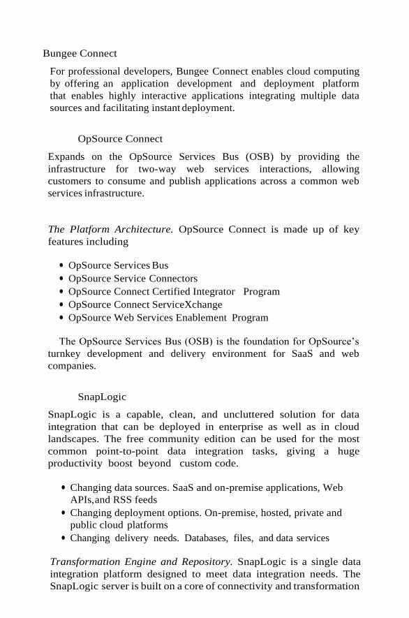
Bungee Connect
For professional developers, Bungee Connect enables cloud computing
by offering an application development and deployment platform
that enables highly interactive applications integrating multiple data
sources and facilitating instant deployment.
OpSource Connect
Expands on the OpSource Services Bus (OSB) by providing the
infrastructure for two-way web services interactions, allowing
customers to consume and publish applications across a common web
services infrastructure.
The Platform Architecture. OpSource Connect is made up of key
features including
● OpSource Services Bus
● OpSource Service Connectors
● OpSource Connect Certified Integrator Program
● OpSource Connect ServiceXchange
● OpSource Web Services Enablement Program
The OpSource Services Bus (OSB) is the foundation for OpSource’s
turnkey development and delivery environment for SaaS and web
companies.
SnapLogic
SnapLogic is a capable, clean, and uncluttered solution for data
integration that can be deployed in enterprise as well as in cloud
landscapes. The free community edition can be used for the most
common point-to-point data integration tasks, giving a huge
productivity boost beyond custom code.
● Changing data sources. SaaS and on-premise applications, Web
APIs, and RSS feeds
● Changing deployment options. On-premise, hosted, private and
public cloud platforms
● Changing delivery needs. Databases, files, and data services
Transformation Engine and Repository. SnapLogic is a single data
integration platform designed to meet data integration needs. The
SnapLogic server is built on a core of connectivity and transformation

components, which can be used to solve even the most complex data
integration scenarios.
The SnapLogic designer provides an initial hint of the web principles
at work behind the scenes. The SnapLogic server is based on the web
architecture and exposes all its capabilities through web interfaces to
outside world.
The Pervasive DataCloud
Platform (figure 3.6) is unique multi-tenant platform. It provides
dynamic “compute capacity in the sky” for deploying on-demand
integration and other
Scalable Computing Cluster
SaaS
Applic
ation
SaaS
Applic
ation
Managem ent
Resources
Schedule Events
eCommerce
Users Load Balancer
&
Message Queues
Engine
Queue
Listen
er
Engine
Queue
Listen
er
Engine
Queue
Listen
er
Engine
Queue
Listen
er
Engine Queue
Listener

Customer Customer
FIGURE 3.6. Pervasive Integrator Connects Different
Resources.
data-centric applications. Pervasive DataCloud is the first multi-tenant
platform for delivering the following.
1. Integration as a Service (IaaS) for both hosted and on-premises
applications and data sources
2. Packaged turnkey integration
3. Integration that supports every integration scenario
4. Connectivity to hundreds of different applications and data
sources
Pervasive DataCloud hosts Pervasive and its partners’ data-centric
applications. Pervasive uses Pervasive DataCloud as a platform for
deploying on-demand integration via
● The Pervasive DataSynch family of packaged integrations. These
are highly affordable, subscription-based, and packaged integration
solutions.
● Pervasive Data Integrator. This runs on the Cloud or on-premises
and is a design-once and deploy anywhere solution to support
every integration scenario
● Data migration, consolidation and conversion
● ETL / Data warehouse
● B2B / EDI integration
● Application integration (EAI)
● SaaS /Cloud integration
● SOA / ESB / Web Services
● Data Quality/Governance
● Hubs
Pervasive DataCloud provides multi-tenant, multi-application and
multicustomer deployment. Pervasive DataCloud is a platform to deploy
applications that are
● Scalable—Its multi-tenant architecture can support multiple users
and applications for delivery of diverse data-centric solutions
such as data integration. The applications themselves scale to

handle fluctuating data volumes.
● Flexible—Pervasive DataCloud supports SaaS-to-SaaS, SaaS-to-on
premise or on-premise to on-premise integration.
● Easy to Access and Configure—Customers can access, configure
and run Pervasive DataCloud-based integration solutions via a
browser.
● Robust—Provides automatic delivery of updates as well as
monitoring activity by account, application or user, allowing
effortless result tracking.
● Secure—Uses the best technologies in the market coupled with the
best data centers and hosting services to ensure that the service
remains secure and available.
● Affordable—The platform enables delivery of packaged solutions
in a SaaS-friendly pay-as-you-go model.
Bluewolf
Has announced its expanded “Integration-as-a-Service” solution, the
first to offer ongoing support of integration projects guaranteeing
successful integration between diverse SaaS solutions, such as
salesforce.com, BigMachines, eAutomate, OpenAir and back office
systems (e.g. Oracle, SAP, Great Plains, SQL Service and MySQL).
Called the Integrator, the solution is the only one to include proactive
monitoring and consulting services to ensure integration success. With
remote monitoring of integration jobs via a dashboard included as part
of the Integrator solution, Bluewolf proactively alerts its customers of
any issues with integration and helps to solves them quickly.
Online MQ
Online MQ is an Internet-based queuing system. It is a complete and
secure online messaging solution for sending and receiving messages
over any network. It is a cloud messaging queuing service.
● Ease of Use. It is an easy way for programs that may each be
running on different platforms, in different systems and different
networks, to communicate with each other without having to write
any low-level communication code.
● No Maintenance. No need to install any queuing software/server
and no need to be concerned with MQ server uptime, upgrades and
maintenance.
● Load Balancing and High Availability. Load balancing can be
achieved on a busy system by arranging for more than one program

instance to service a queue. The performance and availability
features are being met through clustering. That is, if one system
fails, then the second system can take care of users’ requests
without any delay.
● Easy Integration. Online MQ can be used as a web-service (SOAP)
and as a REST service. It is fully JMS-compatible and can hence
integrate easily with any Java EE application servers. Online MQ is
not limited to any specific platform, programming language or
communication protocol.
CloudMQ
This leverages the power of Amazon Cloud to provide enterprise-grade
message queuing capabilities on demand. Messaging allows us to
reliably break up a single process into several parts which can then be
executed asynchronously.
Linxter
Linxter is a cloud messaging framework for connecting all kinds of
applications, devices, and systems. Linxter is a behind-the-scenes,
messageoriented and cloud-based middleware technology and smoothly
automates the complex tasks that developers face when creating
communication-based products and services.
Online MQ, CloudMQ and Linxter are all accomplishing message-
based application and service integration. As these suites are being
hosted in clouds, messaging is being provided as a service to hundreds
of distributed and enterprise applications using the much-maligned
multi-tenancy property. “Messaging middleware as a service (MMaaS)”
is the grand derivative of the SaaS paradigm.
SaaS INTEGRATION SERVICES
We have seen the state-of-the-art cloud-based data integration
platforms for real-time data sharing among enterprise information
systems and cloud applications.
There are fresh endeavours in order to achieve service composition in
cloud ecosystem. Existing frameworks such as service component
architecture (SCA) are being revitalised for making it fit for cloud
environments. Composite applications, services, data, views and
processes will be become cloud-centric and hosted in order to support
spatially separated and heterogeneous systems.
Informatica On-Demand
Informatica offers a set of innovative on-demand data integration

solutions called Informatica On-Demand Services. This is a cluster of
easy-to-use SaaS offerings, which facilitate integrating data in SaaS
applications, seamlessly and securely across the Internet with data in
on-premise applications. There are a few key benefits to leveraging this
maturing technology.
● Rapid development and deployment with zero maintenance of the
integration technology.
● Automatically upgraded and continuously enhanced by vendor.
● Proven SaaS integration solutions, such as integration with
Salesforce
.com, meaning that the connections and the metadata
understanding are provided.
● Proven data transfer and translation technology, meaning that
core integration services such as connectivity and semantic
mediation are built into the technology.
Informatica On-Demand has taken the unique approach of moving
its industry leading PowerCenter Data Integration Platform to the
hosted model and then configuring it to be a true multi-tenant
solution.
Microsoft Internet Service Bus (ISB)
Azure is an upcoming cloud operating system from Microsoft. This
makes development, depositing and delivering Web and Windows
application on cloud centers easier and cost-effective.
Microsoft .NET Services. is a set of Microsoft-built and hosted cloud
infrastructure services for building Internet-enabled applications and the
ISB acts as the cloud middleware providing diverse applications with a
common infrastructure to name, discover, expose, secure and
orchestrate web services. The following are the three broad areas.
.NET Service Bus. The .NET Service Bus (figure 3.7) provides a hosted,
secure, and broadly accessible infrastructure for pervasive
communication,
Console Application Exposing Web Services
via Service Bus

FIGURE 3.7. .NET Service Bus.
End Users End Users
Google App Engine Application
Azure Service Platform .Net Services Service Bus
Windows Azure Applications

large-scale event distribution, naming, and service publishing. Services
can be exposed through the Service Bus Relay, providing connectivity
options for service endpoints that would otherwise be difficult or
impossible to reach.
.NET Access Control Service. The .NET Access Control Service is a
hosted, secure, standards-based infrastructure for multiparty, federated
authentication, rules-driven, and claims-based authorization.
.NET Workflow Service. The .NET Workflow Service provide a hosted
environment for service orchestration based on the familiar Windows
Workflow Foundation (WWF) development experience.
The most important part of the Azure is actually the service bus
represented as a WCF architecture. The key capabilities of the Service
Bus are
● A federated namespace model that provides a shared, hierarchical
namespace into which services can be mapped.
● A service registry service that provides an opt-in model for
publishing service endpoints into a lightweight, hierarchical, and
RSS-based discovery mechanism.
● A lightweight and scalable publish/subscribe event bus.
● A relay and connectivity service with advanced NAT traversal and
pullmode message delivery capabilities acting as a “perimeter
network (also known as DMZ, demilitarized zone, and screened
subnet) in the sky”
Relay Services. Often when we connect a service, it is located behind
the firewall and behind the load balancer. Its address is dynamic
and can be
Relay Service
Client Service

FIGURE 3.8. The .NET Relay Service.
resolved only on local network. When we are having the service call-
backs to the client, the connectivity challenges lead to scalability,
availability and security issues. The solution to Internet connectivity
challenges is instead of connecting client directly to the service we can
use a relay service as pictorially represented in the relay service figure
3.8.
BUSINESSES-TO-BUSINESS INTEGRATION (B2Bi) SERVICES
B2Bi has been a mainstream activity for connecting geographically
distributed businesses for purposeful and beneficial cooperation.
Products vendors have come out with competent B2B hubs and suites
for enabling smooth data sharing in standards-compliant manner among
the participating enterprises.
Just as these abilities ensure smooth communication between
manufacturers and their external suppliers or customers, they also
enable reliable interchange between hosted and installed applications.
The IaaS model also leverages the adapter libraries developed by
B2Bi vendors to provide rapid integration with various business
systems.
Cloudbased Enterprise Mashup Integration Services for B2B Scenarios
. There is a vast need for infrequent, situational and ad-hoc B2B
applications desired by the mass of business end-users..
Especially in the area of applications to support B2B collaborations,
current offerings are characterized by a high richness but low reach,
like B2B hubs that focus on many features enabling electronic
collaboration, but lack availability for especially small organizations
or even individuals.
Enterprise Mashups, a kind of new-generation Web-based
applications, seem to adequately fulfill the individual and
heterogeneous requirements of end-users and foster End User
Development (EUD).
Another challenge in B2B integration is the ownership of and
responsibility for processes. In many inter-organizational settings,
business processes are only sparsely structured and formalized, rather
loosely coupled and/or based on ad-hoc cooperation. Inter-
organizational collaborations tend to involve more and more
participants and the growing number of participants also draws a huge
amount of differing requirements.
Now, in supporting supplier and partner co-innovation and customer
cocreation, the focus is shifting to collaboration which has to embrace

the participants, who are influenced yet restricted by multiple domains
of control and disparate processes and practices.
Both Electronic data interchange translators (EDI) and Managed file
transfer (MFT) have a longer history, while B2B gateways only have
emerged during the last decade.
Enterprise Mashup Platforms and Tools.
Mashups are the adept combination of different and distributed
resources including content, data or application functionality. Resources
represent the core building blocks for mashups. Resources can be
accessed through APIs, which encapsulate the resources and describe
the interface through which they are made available. Widgets or gadgets
primarily put a face on the underlying resources by providing a
graphical representation for them and piping the data received from the
resources. Piping can include operators like aggregation, merging or
filtering. Mashup platform is a Web based tool that allows the creation
of Mashups by piping resources into Gadgets and wiring Gadgets
together.
The Mashup integration services are being implemented as a
prototype in the FAST project. The layers of the prototype are
illustrated in figure 3.9 illustrating the architecture, which describes
how these services work together. The authors of this framework have
given an outlook on the technical realization of the services using cloud
infrastructures and services.

COMPANY A COMPANY B
FIGURE 3.9. Cloudbased Enterprise Mashup Integration Platform
Architecture.
To simplify this, a Gadget could be provided for the end-user. The
routing engine is also connected to a message queue via an API. Thus,
different message queue engines are attachable. The message queue is
responsible for storing and forwarding the messages controlled by the
routing engine. Beneath the message queue, a persistent storage, also
connected via an API to allow exchangeability, is available to store
large data. The error handling and monitoring service allows tracking
the message-flow to detect errors and to collect statistical data. The
HTTP
Browser
HTTP
Browser
HTTP
Browser
HTTP
Browser
HTTP
Browser
HTTP
Browser
Enterprise Mashup Platform
(i.e. FAST)
Enterprise Mashup Platform
(i.e. SAP Research Rooftop)
R
REST
Integration Service Logic
Identity
Management
Routing Engine
Error Handling
and Monitoring Persistent
Storage Organization
Cloud Based
Services
R R R R R R
R
REST
Mashup Integration
Services
Platform
(i.e., Google
App. Engine)
R
Translation
Engine Semantic
R R
Message
Queue Infrastructure
R R
Op
enID
/Oau
th
Mu
le
on
Dem
and
Mu
le
on
Dem
and
Am
azo
n S
3
Am
azo
n S
QS

Mashup integration service is hosted as a cloud-based service. Also,
there are cloud-based services available which provide the functionality
required by the integration service. In this way, the Mashup integration
service can reuse and leverage the existing cloud services to speed up
the implementation.
Message Queue. The message queue could be realized by using
Amazon’s Simple Queue Service (SQS). SQS is a web-service which
provides a queue for messages and stores them until they can be
processed. The Mashup integration services, especially the routing
engine, can put messages into the queue and recall them when they are
needed.
Persistent Storage. Amazon Simple Storage Service5 (S3) is also a
webservice. The routing engine can use this service to store large files.
Translation Engine. This is primarily focused on translating between
different protocols which the Mashup platforms it connects can
understand, e.g. REST or SOAP web services. However, if the need of
translation of the objects transferred arises, this could be attached to the
translation engine.
Interaction between the Services. The diagram describes the process of
a message being delivered and handled by the Mashup Integration
Services Platform. The precondition for this process is that a user
already established a route to a recipient.
A FRAMEWORK OF SENSOR—CLOUD INTEGRATION
In the past few years, wireless sensor networks (WSNs) have been
gaining significant attention because of their potentials of enabling of
novel and attractive solutions in areas such as industrial automation,
environmental monitoring, transportation business, health-care etc.
With the faster adoption of micro and nano technologies, everyday
things are destined to become digitally empowered and smart in their
operations and offerings. Thus the goal is to link smart materials,
appliances, devices, federated messaging middleware, enterprise
information systems and packages, ubiquitous services, handhelds, and
sensors with one another smartly to build and sustain cool, charismatic
and catalytic situation-aware applications.

Traditional HPC approach like Sensor-Grid model can be used in this
case, but setting up the infrastructure to deploy it so that it can scale out
quickly is not easy in this environment. However, the cloud paradigm is
an excellent move.
Here, the researchers need to register their interests to get various
patients’ state (blood pressure, temperature, pulse rate etc.) from bio-
sensors for largescale parallel analysis and to share this information
with each other to find useful solution for the problem. So the sensor
data needs to be aggregated, processed and disseminated based on
subscriptions.
To integrate sensor networks to cloud, the authors have proposed a
contentbased pub-sub model. In this framework, like MQTT-S, all of
the system complexities reside on the broker’s side but it differs from
MQTT-S in that it uses content-based pubsub broker rather than topic-
based which is suitable for the application scenarios considered.
To deliver published sensor data or events to subscribers, an efficient
and scalable event matching algorithm is required by the pub-sub
broker.
Moreover, several SaaS applications may have an interest in the same
sensor data but for different purposes. In this case, the SA nodes would
need to manage and maintain communication means with multiple
applications in parallel. This might exceed the limited capabilities of the
simple and low-cost SA devices. So pub-sub broker is needed and it is
located in the cloud side because of its higher performance in terms of
bandwidth and capabilities. It has four components describes as
follows:
Avirtualcommunity consistingofteam of researchers havecome togetherto
solve a complex problem and they need data storage, compute capability,
security; and they need it all provided now. For example, this team is
working on an outbreak of a new virus strain moving through a population.
This requires more than a Wiki or other social organization tool. They
deploy bio-sensors on patient body to monitor patient condition
continuously and to use this data for large and multi-scale simulations to
track the spread of infection as well as the virus mutation and possible cures.
This may require computational resources and a platform for sharing data
and results that are not immediately available to the team.

FIGURE 3.10. The Framework Architecture of Sensor—Cloud
Integration.
Stream monitoring and processing component (SMPC). The sensor
stream comes in many different forms. In some cases, it is raw data that
must be captured, filtered and analyzed on the fly and in other cases, it is
stored or cached. The style of computation required depends on the
nature of the streams. So the SMPC component running on the
cloud monitors the event streams and invokes correct analysis method.
Depending on the data rates and the amount of processing that is
required, SMP manages parallel execution framework on cloud.
Registry component (RC). Different SaaS applications register to pub-sub
broker for various sensor data required by the community user.
Analyzer component (AC). When sensor data or events come to the pub-
sub broker, analyzer component determines which applications they are
belongs to and whether they need periodic or emergency deliver.
Disseminator component (DC). For each SaaS application, it disseminates
sensor data or events to subscribed users using the event matching
algorithm. It can utilize cloud’s parallel execution framework for fast event
delivery. The pub-sub components workflow in the framework is as
Application Specific
Services
(SaaS)
Servers
Mediator Service
Registry
WSN 1 1 1 1 1
Gateway
3
2
System
Manager 3 Provisioning
Manager
3
Actuator Gateway 2
3
Monitoring
and Metering
4
Sensor 4
Pub/Sub Broker
4
Registry WSN 2
Event Gateway
3
Monitoring Analyzer and
Processing Dissem- inator
Sensor
Policy
Repository
Actuator Gateway Sensor
WSN 2
Collaborator Agent
Cloud Provider (CLP)
Social Network
of doctors for
monitoring
patient
healthcare for
virusinfection
Environmental
data analysis
and
sharingportal
Urban Trafic
prediction
and
analysisnetwork
Other data
analysis or
socialnetwork

follows:
Users register their information and subscriptions to various SaaS
applications which then transfer all this information to pub/sub broker
registry. When sensor data reaches to the system from gateways,
event/stream monitoring and processing component (SMPC) in the pub/sub
broker determines whether it needs processing or just store for periodic
send or for immediate delivery.
Mediator. The (resource) mediator is a policy-driven entity within a VO to
ensure that the participating entities are able to adapt to changing
circumstances and are able to achieve their objectives in a dynamic and
uncertain environment.
Policy Repository (PR). The PR virtualizes all of the policies within the
VO. It includes the mediator policies, VO creation policies along with any
policies for resources delegated to the VO as a result of a collaborating
arrangement.
Collaborating Agent (CA). The CA is a policy-driven resource discovery
module for VO creation and is used as a conduit by the mediator to
exchange policy and resource information with other CLPs.
SaaS INTEGRATION APPLIANCES
Appliances are a good fit for high-performance requirements. Clouds too
have gone in the same path and today there are cloud appliances (also
termed as “cloud in a box”). In this section, we are to see an
integration appliance.
Cast Iron Systems . This is quite different from the above-mentioned
schemes. Appliances with relevant software etched inside are being
established as a high-performance and hardware-centric solution for several
IT needs.
Cast Iron Systems (www.ibm.com) provides pre-configured solutions for
each of today’s leading enterprise and On-Demand applications. These
solutions, built using the Cast Iron product offerings offer out-of-the-box
connectivity to specific applications, and template integration processes
(TIPs) for the most common integration scenarios.

THE ENTERPRISE CLOUD COMPUTING
PARADIGM
Cloud computing is still in its early stages and constantly undergoing
changes as new vendors, offers, services appear in the cloud market.
Enterprises will place stringent requirements on cloud providers to pave
the way for more widespread adoption of cloud computing, leading
to what is known as the enterprise cloud paradigm computing.
Enterprise cloud computing is the alignment of a cloud computing
model with an organization’s business objectives (profit, return on
investment, reduction of operations costs) and processes. This chapter
explores this paradigm with respect to its motivations, objectives,
strategies and methods.
Section 4.2 describes a selection of deployment models and strategies
for enterprise cloud computing, while Section 4.3 discusses the issues of
moving [traditional] enterprise applications to the cloud. Section 4.4
describes the technical and market evolution for enterprise cloud
computing, describing some potential opportunities for multiple
stakeholders in the provision of enterprise cloud computing.

BACKGROUND
According to NIST [1], cloud computing is composed of five essential
characteristics: on-demand self-service, broad network access, resource
pooling, rapid elasticity, and measured service. The ways in which these
characteristics are manifested in an enterprise context vary according to the
deployment model employed.
Relevant Deployment Models for Enterprise Cloud Computing
There are some general cloud deployment models that are accepted by the
majority of cloud stakeholders today, as suggested by the references [1] and
and discussed in the following:
● Public clouds are provided by a designated service provider for general
public under a utility based pay-per-use consumption model.
● Private clouds are built, operated, and managed by an organization for its
internal use only to support its business operations exclusively.
● Virtual private clouds are a derivative of the private cloud deployment
model but are further characterized by an isolated and secure segment
of resources, created as an overlay on top of public cloud infrastructure
using advanced network virtualization capabilities..
● Community clouds are shared by several organizations and support a
specific community that has shared concerns (e.g., mission, security
requirements, policy, and compliance considerations).
● Managed clouds arise when the physical infrastructure is owned by and/or
physically located in the organization’s data centers with an extension of
management and security control plane controlled by the managed service
provider .
● Hybrid clouds are a composition of two or more clouds (private,
community, or public) that remain unique entities but are bound
together by standardized or proprietary technology that enables data
and application portability (e.g., cloud bursting for load-balancing
between clouds).
Adoption and Consumption Strategies
The selection of strategies for enterprise cloud computing is critical for IT
capability as well as for the earnings and costs the organization experiences,
motivating efforts toward convergence of business strategies and IT. Some
critical questions toward this convergence in the enterprise cloud paradigm are
asfollows:
● Will an enterprise cloud strategy increase overall business value?
● Are the effort and risks associated with transitioning to an enterprise
cloud strategy worth it?
● Which areas of business and IT capability should be considered for the

enterprise cloud?
● Which cloud offerings are relevant for the purposes of an organization?
● How can the process of transitioning to an enterprise cloud strategy be
piloted and systematically executed?
These questions are addressed from two strategic perspectives: (1) adoption
and (2) consumption. Figure 4.1 illustrates a framework for enterprise cloud
adoption strategies, where an organization makes a decision to adopt a
cloud computing model based on fundamental drivers for cloud computing—
scalability, availability, cost and convenience. The notion of a Cloud Data
Center (CDC) is used, where the CDC could be an external, internal or
federated provider of infrastructure, platform or software services.
An optimal adoption decision cannot be established for all cases because the
types of resources (infrastructure, storage, software) obtained from a CDC
depend on the size of the organisation understanding of IT impact on business,
predictability of workloads, flexibility of existing IT landscape and available
budget/resources for testing and piloting. The strategic decisions using these
four basic drivers are described in following, stating objectives, conditions and
actions.

Cloud Data Center(s)
(CDC)
Scalability-driven: Use of cloud
resources to support additional
load or as back-up.
Availability-driven:
Use of load-balanced
and localised cloud
resources to increase
availability and
reduce response time
Market-driven:
Users and
providers of
cloud resources
make decisions
based on the
potential saving
and profit
Conveniencedriv
en: Use cloud
resources so that
there is no need to
maintain local
resources.
FIGURE 4.1. Enterprise cloud adoption strategies using fundamental cloud drivers.
1. Scalability-Driven Strategy. The objective is to support increasing
workloads of the organization without investment and expenses
exceeding returns.
2. Availability-Driven Strategy. Availability has close relations to scalability
but is more concerned with the assurance that IT capabilities and functions
are accessible, usable and acceptable by the standards of users.
3. Market-Driven Strategy. This strategy is more attractive and viable for
small, agile organizations that do not have (or wish to have) massive
investments in their IT infrastructure.

(1) Software Provision: Cloud provides instances
of software but data is maintained within user’s
data center
(2) Storage Provision: Cloud provides data
management and software accesses data
remotely from user’s data center
(3) Solution Provision: Software and storage
are maintained in cloud and the user does not
maintain a data center
(4) Redundancy Services: Cloud is used as an
alternative or extension of user’s data center
for software and storage

FIGURE 4.2. Enterprise cloud consumption strategies.
on their profiles and requests service requirements .
4. Convenience-Driven Strategy. The objective is to reduce the load and
need for dedicated system administrators and to make access to IT
capabilities by users easier, regardless of their location and connectivity
(e.g. over the Internet).
There are four consumptions strategies identified, where the differences in
objectives, conditions and actions reflect the decision of an organization to
trade-off hosting costs, controllability and resource elasticity of IT resources
for software and data. These are discussed in the following.
1. Software Provision. This strategy is relevant when the elasticity
requirement is high for software and low for data, the controllability
concerns are low for software and high for data, and the cost reduction
concerns for software are high, while cost reduction is not a priority for
data, given the high controllability concerns for data, that is, data are
highly sensitive.
2. Storage Provision. This strategy is relevant when the elasticity
requirements is high for data and low for software, while the
controllability of software is more critical than for data. This can be the
case for data intensive applications, where the results from processing in
the application are more critical and sensitive than the data itself.
3. Solution Provision. This strategy is relevant when the elasticity and cost
reduction requirements are high for software and data, but the
controllability requirements can be entrusted to the CDC.
4. Redundancy Services. This strategy can be considered as a hybrid
enterprise cloud strategy, where the organization switches between
traditional, software, storage or solution management based on changes
in its operational conditions and business demands.
Even though an organization may find a strategy that appears to provide it
significant benefits, this does not mean that immediate adoption of the strategy
is advised or that the returns on investment will be observed immediately.
ISSUES FOR ENTERPRISE APPLICATIONS ON THE CLOUD
Enterprise Resource Planning (ERP) is the most comprehensive definition of
enterprise application today. For these reasons, ERP solutions have emerged as
the core of successful information management and the enterprise
backbone of nearly any organization . Organizations that have successfully
implemented the ERP systems are reaping the benefits of having integrating
working environment, standardized process and operational benefits to the
organization .
One of the first issues is that of infrastructure availability. Al-Mashari and

Yasser argued that adequate IT infrastructure, hardware and networking are
crucial for an ERP system’s success.
One of the ongoing discussions concerning future scenarios considers varying
infrastructure requirements and constraints given different workloads and
development phases. Recent surveys among companies in North America
and Europe with enterprise-wide IT systems showed that nearly all kinds of
workloads are seen to be suitable to be transferred to IaaS offerings.
Considering Transactional and Analytical Capabilities
Transactional type of applications or so-called OLTP (On-line Transaction
Processing) applications, refer to a class of systems that manage
transactionoriented applications, typically using relational databases. These
applications rely on strong ACID (atomicity, consistency, isolation,
durability) properties and are relatively write/update-intensive. Typical OLTP-
type ERP components are sales and distributions (SD), banking and financials,
customer relationship management (CRM) and supply chain management
(SCM).
One can conclude that analytical applications will benefit more than their
transactional counterparts from the opportunities created by cloud computing,
especially on compute elasticity and efficiency.
TRANSITION CHALLENGES
The very concept of cloud represents a leap from traditional approach for IT to
deliver mission critical services. With any leap comes the gap of risk and
challenges to overcome. These challenges can be classified in five different
categories, which are the five aspects of the enterprise cloud stages: build,
develop, migrate, run, and consume (Figure 4.3).
The requirement for a company-wide cloud approach should then become
the number one priority of the CIO, especially when it comes to having a
coherent and cost effective development and migration of services on this
architecture.
Develop
Build Run Consume
Migrate

FIGURE 4.3. Five stages of the cloud.
A second challenge is migration of existing or “legacy” applications to “the
cloud.” The expected average lifetime of ERP product is B15 years, which
means that companies will need to face this aspect sooner than later as they try
to evolve toward the new IT paradigm.
The ownership of enterprise data conjugated with the integration with others
applications integration in and from outside the cloud is one of the key
challenges. Future enterprise application development frameworks will need to
enable the separation of data management from ownership. From this, it can
be extrapolated that SOA, as a style, underlies the architecture and, moreover,
the operation of the enterprise cloud.
One of these has been notoriously hard to upgrade: the human factor;
bringing staff up to speed on the requirements of cloud computing with respect
to architecture, implementation, and operation has always been a tedious task.
Once the IT organization has either been upgraded to provide cloud or is
able to tap into cloud resource, they face the difficulty of maintaining the
services in the cloud. The first one will be to maintain interoperability between
in-house infrastructure and service and the CDC (Cloud Data Center).
Before leveraging such features, much more basic functionalities are
problematic: monitoring, troubleshooting, and comprehensive capacity
planning are actually missing in most offers. Without such features it becomes
very hard to gain visibility into the return on investment and the consumption
of cloud services.
Today there are two major cloud pricing models: Allocation based and
Usage based . The first one is provided by the poster child of cloud computing,
namely, Amazon. The principle relies on allocation of resource for a fixed
amount of time. As companies need to evaluate the offers they need to also
include the hidden costs such as lost IP, risk, migration, delays and provider
overheads. This combination can be compared to trying to choose a new mobile
with carrier plan.The market dynamics will hence evolve alongside the
technology for the enterprise cloud computing paradigm.
ENTERPRISE CLOUD TECHNOLOGY AND MARKET EVOLUTION
This section discusses the potential factors which will influence this evolution of
cloud computing and today’s enterprise landscapes to the enterprise computing
paradigm, featuring the convergence of business and IT and an open, service
oriented marketplace.
Technology Drivers for Enterprise Cloud Computing Evolution
This will put pressure on cloud providers to build their offering on open
interoperable standards to be considered as a candidate by enterprises. There
have been a number initiatives emerging in this space. Amazon, Google, and
Microsoft, who currently do not actively participate in these efforts. True
interoperabilityacross

the board in the near future seems unlikely. However, if achieved, it could lead
to facilitation of advanced scenarios and thus drive the mainstream adoption of
the enterprise cloud computing paradigm.
Part of preserving investments is maintaining the assurance that cloud
resources and services powering the business operations perform according
to the business requirements. Underperforming resources or service disruptions
lead to business and financial loss, reduced business credibility, reputation,
and marginalized user productivity. Another important factor in this regard is
lack of insights into the performance and health of the resources and service
deployed on the cloud, such that this is another area of technology evolution
that will be pushed.
This would prove to be a critical capability empowering third-party
organizations to act as independent auditors especially with respect to SLA
compliance auditing and for mediating the SLA penalty related issues.
Emerging trend in the cloud application space is the divergence from the
traditional RDBMS based data store backend. Cloud computing has given rise
to alternative data storage technologies (Amazon Dynamo, Facebook
Cassandra, Google BigTable, etc.) based on key-type storage models as
compared to the relational model, which has been the mainstream choice for
data storage for enterprise applications.
As these technologies evolve into maturity, the PaaS market will consolidate
into a smaller number of service providers. Moreover, big traditional software
vendors will also join this market which will potentially trigger this
consolidation through acquisitions and mergers. These views are along the
lines of the research published by Gartner. Gartner predicts that from 2011 to
2015 market competition and maturing developer practises will drive
consolidation around a small group of industry-dominant cloud technology
providers.
A recent report published by Gartner presents an interesting perspective on
cloud evolution. The report argues that as cloud services proliferate, services
would become complex to be handled directly by the consumers. To cope
with these scenarios, meta-services or cloud brokerage services will emerge.
These brokerages will use several types of brokers and platforms to enhance
service delivery and, ultimately service value. According to Gartner, before
these scenarios can be enabled, there is a need for brokerage business to use
these brokers and platforms. According to Gartner, the following types of cloud
service brokerages (CSB) are foreseen:
● Cloud Service Intermediation. An intermediation broker providers a
service that directly enhances a given service delivered one or more service
consumers, essentially on top of a given service to enhance a specific
capability.
● Aggregation. An aggregation brokerage service combines multiple
services into one or more new services.
● Cloud Service Arbitrage. These services will provide flexibility and
opportunistic choices for the service aggregator.

The above shows that there is potential for various large, medium, and
small organizations to become players in the enterprise cloud marketplace.
The dynamics of such a marketplace are still to be explored as the enabling
technologies and standards continue to mature.
BUSINESS DRIVERS TOWARD A MARKETPLACE FOR
ENTERPRISE CLOUD COMPUTING
In order to create an overview of offerings and consuming players on the
market, it is important to understand the forces on the market and motivations
of each player.
The Porter model consists of five influencing factors/views (forces) on the
market (Figure 4.4). The intensity of rivalry on the market is traditionally
influenced by industry-specific characteristics :
● Rivalry: The amount of companies dealing with cloud and virtualization
technology is quite high at the moment; this might be a sign for high
FIGURE 4.4. Porter’s five forces market model (adjusted for the cloud market) .
New Market Entrants
• Geographical factors
• Entrant strategy
• Routes to market
Suppliers
• Level of quality
• Supplier’s size
• Bidding processes/
capabilities
Buyers (Consumers)
• Buyer size
• Buyers number
• Product/service
• Requirements
Technology Development
• Substitutes
• Trends
• Legislative effects
Cloud Market
• Cost structure
• Product/service ranges
• Differentiation, strategy
• Number/size of players

BUSINESS DRIVERS TOWARD A MARKETPLACE FOR ENTERPRISE 113
rivalry. But also the products and offers are quite various, so many niche
products tend to become established.
● Obviously, the cloud-virtualization market is presently booming and will
keep growing during the next years. Therefore the fight for customers and
struggle for market share will begin once the market becomes saturated
and companies start offering comparable products.
● The initial costs for huge data centers are enormous. By building up
federations of computing and storing utilities, smaller companies can try
to make use of this scale effect as well.
● Low switching costs or high exit barriers influence rivalry. When a
customer can freely switch from one product to another, there is a greater
struggle to capture customers. From the opposite point of view high exit
barriers discourage customers to buy into a new technology. The trends
towards standardization of formats and architectures try to face this
problem and tackle it. Most current cloud providers are only paying
attention to standards related to the interaction with the end user.
However, standards for clouds interoperability are still to be developed .
FIGURE 4.5. Dynamic business models (based on [49] extend by
influence factors identified by[50]).
Market
Regulations Business Model Hype Cycle Phase
Market
Technology

.
THE CLOUD SUPPLY CHAIN
One indicator of what such a business model would look like is in the complexity
of deploying, securing, interconnecting and maintaining enterprise landscapes
and solutions such as ERP, as discussed in Section 4.3. The concept of a Cloud
Supply Chain (C-SC) and hence Cloud Supply Chain Management (C-SCM)
appear to be viable future business models for the enterprise cloud computing
paradigm. The idea of C-SCM represents the management of a network of
interconnected businesses involved in the end-to-end provision of product and
service packages required by customers. The established understanding of a
supply chain is two or more parties linked by a flow of goods, information,
and funds [55], [56] A specific definition for a C-SC is hence: “two or more
parties linked by the provision of cloud services, related information
and funds.” Figure 4.6 represents a concept for the C-SC, showing the flow
of products along different organizations such as hardware suppliers, software
component suppliers, data center operators, distributors and the end customer.
Figure 4.6 also makes a distinction between innovative and functional
products in the C-SC. Fisher classifies products primarily on the basis of their
demand patterns into two categories: primarily functional or primarily
innovative [57]. Due to their stability, functional products favor competition,
which leads to low profit margins and, as a consequence of their properties, to
low inventory costs, low product variety, low stockout costs, and low
obsolescence [58], [57]. Innovative products are characterized by additional
(other) reasons for a customer in addition to basic needs that lead to purchase,
unpredictable demand (that is high uncertainties, difficult to forecast and
variable demand), and short product life cycles (typically 3 months to 1
year). Cloud services
Cloud services, information, funds
Fuctional
Data center
operator Distributor
Product Cloud supply chain End
customer
Innovative Hardware
supplier
Component
supplier
Potential Closed Loop Cooperation
FIGURE 4.6. Cloud supply chain (C-SC).
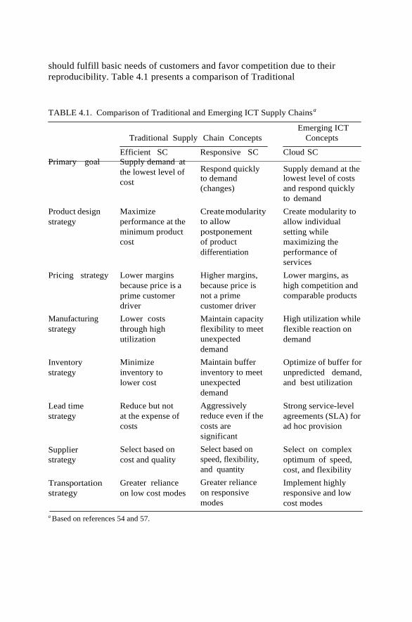
should fulfill basic needs of customers and favor competition due to their
reproducibility. Table 4.1 presents a comparison of Traditional
TABLE 4.1. Comparison of Traditional and Emerging ICT Supply Chainsa
Emerging ICT
Traditional Supply Chain Concepts Concepts
Efficient SC Responsive SC Cloud SC
Primary goal Supply demand at
Product design
strategy
the lowest level of
cost
Maximize
performance at the
minimum product
cost
Respond quickly to demand
(changes)
Create modularity
to allow
postponement
of product
differentiation
Supply demand at the lowest level of costs
and respond quickly
to demand
Create modularity to
allow individual
setting while
maximizing the
performance of
services
Pricing strategy Lower margins
because price is a
prime customer
driver
Higher margins,
because price is
not a prime
customer driver
Lower margins, as
high competition and
comparable products
Manufacturing
strategy
Inventory
strategy
Lead time
strategy
Supplier
strategy
Transportation
strategy
Lower costs
through high
utilization
Minimize
inventory to
lower cost
Reduce but not
at the expense of
costs
Select based on
cost and quality
Greater reliance
on low cost modes
Maintain capacity
flexibility to meet
unexpected
demand
Maintain buffer
inventory to meet
unexpected
demand
Aggressively
reduce even if the
costs are
significant
Select based on
speed, flexibility,
and quantity
Greater reliance
on responsive
modes
High utilization while
flexible reaction on
demand
Optimize of buffer for
unpredicted demand,
and best utilization
Strong service-level
agreements (SLA) for
ad hoc provision
Select on complex
optimum of speed,
cost, and flexibility
Implement highly
responsive and low
cost modes
a Based on references 54 and 57.

Supply Chain concepts such as the efficient SC and responsive SC and a new
concept for emerging ICT as the cloud computing area with cloud services as
traded products.
UNIT – 4 MONITORING, MANAGEMENT AND
APPLICATIONS
AN ARCHITECTURE FOR FEDERATED CLOUD COMPUTING
Utility computing, a concept envisioned back in the 1960s, is finally becoming
a reality. Just as we can power a variety of devices, ranging from a simple
light bulb to complex machinery, by plugging them into the wall, today we
can satisfy, by connecting to the Internet, many of our computing needs,
ranging from full pledge productivity applications to raw compute power in
the form of virtual machines. Cloud computing, in all its different forms, is
rapidly gaining momentum as an alternative to traditional IT, and the
reasons for this are clear: In principle, it allows individuals and companies to
fulfill all their IT needs with minimal investment and controlled expenses
(both capital and operational).
While cloud computing holds a lot of promise for enterprise computing
there are a number of inherent deficiencies in current offerings such as:
● Inherently Limited Scalability of Single-Provider Clouds. Although most
infrastructure cloud providers today claim infinite scalability, in reality it
is reasonable to assume that even the largest players may start facing
scalability problems as cloud computing usage rate increases.
● Lack of Interoperability Among Cloud Providers. Contemporary cloud
technologies have not been designed with interoperability in mind. This
results in an inability to scale through business partnerships across clouds
providers.
● No Built-In Business Service Management Support. Business Service
Management (BSM) is a management strategy that allows businesses to
align their IT management with their high-level business goals.
To address these issues, we present in this chapter a model for business-driven
federation of cloud computing providers, where each provider can buy and sell,
on-demand, capacity from other providers (see Figure 4.1.1).
In this chapter we analyze the requirements for an enterprise-grade cloud
computing offering and identify the main functional components that should
be part of such offering. In addition, we develop from the requirement the basic
principles that we believe are the cornerstone of future cloud computing
offerings. The remainder of this chapter is organized as follows: In Section
we will present use cases and requirements, and in Section 4.1.3 we

expand on the principles of cloud computing derived from these requirements.
In Section 4.1.4 we will present a model for federated cloud computing
infrastructure and provide definitions of the concepts used and in Section 4.1.5
we describe the seurity considerations for such system. We conclude with a
summary in Section 4.1.6.
A TYPICAL USE CASE
As a representative of an enterprise-grade application, we have chosen to
analyze SAPt systems and to derive from them general requirements that such
application might have from a cloud computing provider.
FIGURE 4.1.1. Model for federated cloud computing: (a) Different cloud providers
collaborate by sharing their resources while keeping thick walls in between them; that is,
each is an independent autonomous entity. (b) Applications running in this cloud of
clouds should be unaware of location; that is, virtual local networks are needed for the
inter-application components to communicate. (c) Cloud providers differentiate from
each in terms of cost and trust level; for example, while a public cloud maybe cheap,
companies will be reluctant to put in there sensitive services.
SAP Systems
SAP systems are used for a variety of business applications that differ by
version and functionality [such as customer relationship management (CRM)
and enterprise resource planning (ERP)].
An SAP system is a typical three-tier system (see Figure 4.1.2) as follows:
● Requests are handled by the SAP Web dispatcher.
● In the middle tier, there are two types of components: multiple stateful
(a)
(b) A Public Cloud
(c)
My P
rivate C
loud

dialog instances (DIs) and a single central instance (CI) that performs
central services.
● A single database management system (DBMS) serves the SAP system.
Storage
FIGURE 4.1.2. Abstraction of an SAP system.
The components can be arranged in a variety of configurations, from a minimal
configuration where all components run on a single machine, to larger ones
where there are several DIs, each running on a separate machine, and a
separate machine with the CI and the DBMS (see Figure 4.1.3)
The Virtualized Data Center Use Case
Consider a data center that consolidates the operation of different types of SAP
applications and all their respective environments (e.g., test, production) using
virtualization technology. The applications are offered as a service to external
customers, or, alternatively, the data center is operated by the IT department of
an enterprise for internal users (i.e., enterprise employees).
We briefly mention here a few aspects that are typical of virtualized data
centers:
(a)
DI/CI
DBMS
DI/CI
DBMS
DI/CI
DBMS
Virtual Execution Environment Host
Browser
Web Dispatcher
DI CI DI
DBMS
Presentation Layer
Application Layer
Database Layer

(b)
FIGURE 4.1.3. Sample SAP system deployments. (a) All components run in the same
virtual execution environment (represented as rounded rectangles); (b) the large
components (CI and DBMS) run each on a dedicated virtual execution environment.
The virtual execution environment host refers to the set of components managing the
virtual environments.
● The infrastructure provider must manage the life cycle of the application
for hundreds or thousands of tenants while keeping a very low total cost
of ownership (TCO).
● Setting up a new tenant in the SaaS for SMBs case is completely
automated by a Web-based wizard.
● The customers are billed a fixed monthly subscription fee or a variable fee
based on their usage of the application. ● There are several well-known approaches to multi-tenancy of the same
database schema .
In summary, the key challenges in all these use cases from the point of view
of the infrastructure provider are:
● Managing thousands of different service components that comprise a
variety of service applications executed by thousands of virtual execution
environments,.
● Consolidating many applications on the same infrastructure, thereby
increasing HW utilization and optimizing power consumption, while
keeping the operational cost at minimum.
● Guaranteeing the individual SLAs of the many customers of the data
center who face different and fluctuating workloads.
Primary Requirements
From the use case discussed in the previous section, we derived the following
main requirements from a cloud computing infrastructure:
● Automated and Fast Deployment. The cloud should support automated
provisioning of complex service applications based on a formal contract
specifying theinfrastructure SLAs.
● Dynamic Elasticity. The cloud should dynamically adjust resource
CI
DBMS
Virtual Execution Environment Host
DI DI

allocation parameters .
● Automated Continuous Optimization. The cloud should continuously
optimize alignment of infrastructure resources management with the high-
level business goals.
THE BASIC PRINCIPLES OF CLOUD COMPUTING
In this section we unravel a set of principles that enable Internet scale cloud
computing services.
Federation
All cloud computing providers, regardless of how big they are, have a finite
capacity. To grow beyond this capacity, cloud computing providers should be
able to form federations of providers such that they can collaborate and share
their resources.
Any federation of cloud computing providers should allow virtual application
to be deployed across federated sites.
Independence
Just as in other utilities, where we get service without knowing the internals
of the utility provider and with standard equipment not specific to any provider
(e.g., telephones), for cloud computing services to really fulfill the computing as
a utility vision, we need to offer cloud computing users full independence.
Isolation
Cloud computing services are, by definition, hosted by a provider that will
simultaneously host applications from many different users. For these users to
move their computing into the cloud, they need warranties from the cloud
computing provider that their stuff is completely isolated from others.
Elasticity
One of the main advantages of cloud computing is the capability to provide, or
release, resources on-demand.
The ability of users to grow their applications when facing an increase of
real-life demand need to be complemented by the ability to scale
Business Orientation
Before enterprises move their mission critical applications to the cloud, cloud
computing providers will need to develop the mechanisms to ensure quality of
service (QoS) and proper support for service-level agreements (SLAs).
Mechanisms to build and maintain trust between cloud computing consumers

VM
I S
MI
and cloud computing providers, as well as between cloud computing providers
among themselves, are essential for the success of any cloud computing
offering.
A MODEL FOR FEDERATED CLOUD COMPUTING
In our model for federated cloud computing we identify two major types of
actors: Service Providers (SPs) are the entities that need computational
resources to offer some service.
To create the illusion of an infinite pool of resources, IPs shared their unused
capacity with each other to create a federation cloud. A Framework Agreement
FIGURE 4.1.4. The RESERVOIR architecture: major components and
interfaces.
We refer to the virtualized computational resources, alongside the
virtualization layer and all the management enablement
components, as the Virtual Execution enviroment Host (VEEH).
With these concepts in mind, we can proceed to define a
reference architecture for federated cloud computing. The design
and implementation of such architecure are the main goals of the
RESERVOIR European research project.The rationale behind this
particular layering is to keep a clear separation of concerns and
responsibilities and to hide low-level infrastructure details and
decisions from high-level management and service providers.
● The Service Manager is the only component within an IP
S
LA
S
A
VMI VMI
Infrastructure Provider (IP)
Service Provider (SP)
Manifest
Service Manager
VEE Manager (VEEM)
VEE Host (VEEH)
(e.g., Hypervisor)
VM
I

that interacts with SPs. It receives Service Manifests,
negotiates pricing, and handles billing. Its two most complex tasks are (1) deploying and provisioning VEEs based on the Service Manifest and (2) monitoring and enforcing SLA compliance by throttling a service application’s capacity.
● The Virtual Execution Environment Manager (VEEM) is responsible for
the optimal placement of VEEs into VEE Hosts subject to constraints
determined by the Service Manager. The continuous optimization process is
driven by a site-specific programmable utility function.
● The Virtual Execution Environment Host (VEEH) is responsible for the
basic control and monitoring of VEEs and their resources. Moreover,
VEEHs must support transparent VEE migration to any compatible VEEH
within the federated cloud, regardless of site location or network and
storage configurations.
Features of Federation Types
Federations of clouds may be constructed in various ways, with disparate
feature sets offered by the underlying implementation architecture. This section
is devoted to present these differentiating features. Using these features as a
base, a number of federation scenarios are defined, comprised of subsets of this
feature set.
The first feature to consider is the framework agreement support:
Framework agreements, as defined in the previous section, may either be
supported by the architecture or not.
The ability to migrate machines across sites defines the federated migration
support. There are two types of migration: cold and hot (or live). In cold
migration, the VEE is suspended and experiences a certain amount of
downtime while it is being transferred.
Focusing on networks, there can be cross-site virtual network support: VEEs
belonging to a service are potentially connected to virtual networks, should this
be requested by the SP.
Information disclosure within the federation has also to be taken into account.
The sites in the federation may provide information to different degrees
.Information regarding deployed VEEs will be primarily via the monitoring
system, whereas some information may also potentially be exposed via the
VMI as response to a VEE deployment request.
Federation Scenarios
In this section, a number of federation scenarios are presented, ranging from a
baseline case to a full-featured federation. These scenarios have various
requirements on the underlying architecture, and we use the features presented
in previous section as the basis for differentiating among them.
The baseline federation scenario provides only the very basic required for
supporting opportunistic placement of VEEs at a remote site. The basic
federation scenario includes a number of features that the baseline federation

does not, such as framework agreements, cold migration, and retention of
public IP addresses. Notably missing is (a) support for hot migration and (b)
cross-site virtual network functionality.The fullfeatured federation scenario
offers the most complete set of features, including hot migration of VEEs.
Layers Enhancement for Federation
Taking into account the different types of federation, a summary of the features
needed in the different layers of the RESERVOIR architecture to achieve
federation is presented.
Service Manager. The baseline federation is the most basic federation
scenario, but even here the SM must be allowed to specify placement
restrictions when a service is deployed. Deployment restrictions are associated
to an specific VEE and passed down to the VEEM along with any other
specific VEE metadata when the VEE is issued for creation through VMI. Two
kinds of deployment restrictions are envisioned: First, there are affinity
restrictions, related to the relations between VEEs; and second, there can be
site restrictions, related to sites.
In the basic federation scenario, federation uses framework agreement (FA)
between organizations to set the terms and conditions for federation.
Framework agreements are negotiated and defined by individuals, but they are
encoded at the end in the service manager (SM)—in particular, within the
business information data base (BIDB). On the other hand, no additional
functionality is needed from the service manager to implement the full-
featured federation.
Virtual Execution Environment Manager. Very little is needed in the
baseline federation scenario of the VEEM. Regarding advance resource
reservation support, the policy engine must be capable of reserving capacity in the
physical infrastructure given a timeframe for certain VEEs. Therefore, the VEEM
needs to correctly interface with the VAN and be able to express the virtual
network characteristics in a VEEM-to-VEEM connection.
Virtual Execution Environment Host. The ability to monitor a federation is
needed. The RESERVOIR monitoring service supports the asynchronous
monitoring of a cloud data centers0 VEEHs, their VEEs, and the applications
running inside the VEEs. To support federation, the originating data center
must be able to monitor VEEs and their applications running at a remote site.
No further functionality is required for the basic federation in the VEEH
apart from the features described for the baseline scenario. On the other hand,
for the advanced federation one, several features are needed.
Regarding the full-featured federation scenario, hot migration is the
functionality that affects the most what is demanded from VEEH in this
scenario. RESERVOIR’s separation principle requires that each RESERVOIR
site be an autonomous entity. Site configuration, topology, and so on, are not
shared between sites.

SECURITY CONSIDERATIONS
As previously reported, virtualized service-oriented infrastructures provide
computing as a commodity for today’s competitive businesses. Besides
costeffectiveness, .The higher stakes and broader scope of the security
requirements of virtualization infrastructures require comprehensive security
solutions because they are critical to ensure the anticipated adoption of
virtualization solutions by their users and providers. The conception of a
comprehensive security model requires a realistic threat model. Without such a
threat model, security designers risk wasting time and effort implementing
safeguards that do not address any realistic threat.
External Threats
Some threats, related to communication, can be classified as: menin-the-middle,
TCP hijacking (spoofing), service manifest attacks (malicious manifest/SLA
format injection), migration and security policies and identity
theft/impersonation (SP or RESERVOIR site pretends to be someone else), and
so on. The main goals of these threats are to gain unauthorized access to systems
and to impersonate another entity on the network. These techniques allow
the attackers to eavesdrop as well as to change, delete, or divert data. All the
interfaces could be instead exposed to the following attacks: denial of service
(DoS or distributed DoS), flooding, buffer overflow, p2p-attacks, and so on.
Internal Threats
Each RESERVOIR site has a logical representation with three different layers,
but these layers can be compounded by one or more hardware components.
Figure 4.1.5 gives an overview of these entities and relative mapping with a
simplified view of the hardware. It is possible to split the site in two different
virtual zones: control and execution zone; in the control zone the components
are: Service Manager (SM), VEEM (in bridge configuration between control
SP SP
VM image
1 - SMI
2 - VMI SITE: Control zone VM image
Remote Storage
Remote Storage
Router
S
Switch
Server
Service
Manager
VHI
VEE
Manager
Internet VH
Manager
Front-End Web HOST
Router
Switch
VM image
Local Storage
3- SI Interface for VM image VM image

SITE: Execution zone
FIGURE 4.1.5. RESERVOIR site: internal representation.

and execution zone), network components (router, switch, cable, etc.), SMI/
VMI interfaces, and VHI internal interface.
In the execution zone instead there are: VEEH, VEEM (in-bridge
configuration between control and execution zone), VHI internal interface,
network components (router, switch, cable, etc.), network storage (NAS,
databases, etc.), and SI (user access interfaces).
The control zone can be considered a trusted area. Some threats can appear
through the SMI and VEEM interfaces, since they fall into the same cases of
external threats. The internal threats related to these phases can be classified
as follows: (1) threats linked to authentication/communication of SPs and
other RESERVOIR site;
(2) threats related to misbehavior of service resource allocation—to alter the
agreement (manifest) during the translation between service manager and
VEEM malicious component on SM; (3) data export control legislation—on
an international cloud or between two clouds; (4) threats linked to fake
command for placement of VEEs and compromising the data integrity of
the distributed file system (NFS, SAMBA, CIFS); (5) storage data
compromising (fake VEE image); (6) threats linked to compromise data
privacy; (7) threats linked to the underlying hypervisor and OS (VEE could
break hypervisor/ underlying OS security and access other VEE); and (8) data
partitioning between VEE.
To avoid any fraudulent access, the VEEH has to verify authentication/
communication of SPs and other RESERVOIR sites. Thus, the same behavior is
analyzed for all the communications in external threats.
Runtime isolation resolves all the security problems with the underlying OS.
The hypervisor security mechanisms need to be used to provide the isolation.
Network isolation is addressed via the dynamic configuration of network
policies and via virtual circuits that involve routers and switches.
To avoid fake VEE image loading and do not compromise data privacy,
storage isolation has to be performed and secure protocols has to be used.
Protocols like NFS, SAMBA, and CIFS are not secure.
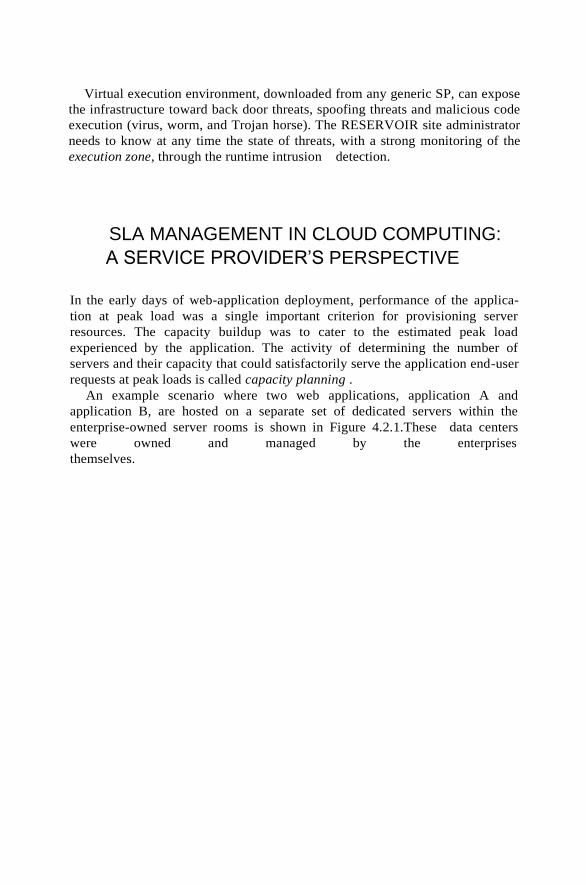
Virtual execution environment, downloaded from any generic SP, can expose
the infrastructure toward back door threats, spoofing threats and malicious code
execution (virus, worm, and Trojan horse). The RESERVOIR site administrator
needs to know at any time the state of threats, with a strong monitoring of the
execution zone, through the runtime intrusion detection.
SLA MANAGEMENT IN CLOUD COMPUTING:
A SERVICE PROVIDER’S PERSPECTIVE
In the early days of web-application deployment, performance of the applica-
tion at peak load was a single important criterion for provisioning server
resources. The capacity buildup was to cater to the estimated peak load
experienced by the application. The activity of determining the number of
servers and their capacity that could satisfactorily serve the application end-user
requests at peak loads is called capacity planning .
An example scenario where two web applications, application A and
application B, are hosted on a separate set of dedicated servers within the
enterprise-owned server rooms is shown in Figure 4.2.1.These data centers
were owned and managed by the enterprises
themselves.

FIGURE 4.2.1. Hosting of applications on servers within enterprise’s data centers.
Furthermore, over the course of time, the number of web applications and
their complexity have grown. Accordingly, enterprises realized that it was
economical to outsource the application hosting activity to third-party
infrastructure providers because:
● The enterprises need not invest in procuring expensive hardware upfront
without knowing the viability of the business.
● The hardware and application maintenance were non-core activities of
their business.
● As the number of web applications grew, the level of sophistication
required to manage the data centers increased manyfold—hence the cost
of maintaining them.
Enterprises developed the web applications and deployed on the infrastruc-
ture of the third-party service providers. These providers get the required
Enterprise Data Centre – Geographically Locked (Managed by Enterprise IT)
Enterprise Data Centre I
Response with certain response time => SLO
Application Service Request
Application I
Application II
User Application III
Enterprise Data Centre II
User
Application Service Request
Application I
Application II
Response with certain response time => SLO
Application III

hardware and make it available for application hosting. Typically, the QoS parameters are related to the availability of the
system CPU, data storage, and network for efficient execution of the application at peak loads. This legal agreement is
known as the service-level agreement (SLA). For example, assume that application A is required to use more quantity of a
resource than originally allocated to it for duration of time t. For that duration the amount of the same resource available to
application B is decreased. This could adversely affect the performance of application B. Similarly, one application should
not access and destroy the data
FIGURE 4.2.2. Dedicated hosting of applications in third party datacenters.
Application Service Provider(ASP)
Enterprise
User Enterprise I Applications
Enterprise II Applications
User
Response with certain response time => SLO
Enterprise III Applications Check for Infrastructure
Availability?
Application Service
Request Service-Level Agreement

Res
ou
rce
Time Time
Time Time
FIGURE 4.2.3. Service consumer and service provider perspective before and after the MSP’s hosting platforms are
virtualized and cloud-enabled. (a) Service consumer perspective earlier. (b) Service consumer perspective now. (c)
Service provider perspec- tive earlier. (d) Service provider perspective now.
and other information of co-located applications. Hence, appropriate measures are needed to guarantee
security and performance isolation. These challenges prevented ASPs from fully realizing the benefits of
co-hosting.
Adoption of virtualization technologies required ASPs to get more detailed insight into the application runtime
characteristics with high accuracy. Based on these characteristics, ASPs can allocate system resources more
efficiently to these applications on-demand, so that application-level metrics can be mon- itored and met
(c) Capacity
Resource usage (App-A)
(a) Capacity
Resource usage (App-A)
(b)
Capacity
Resource usage (App-A)
(d) Capacity
Resource usage (App-B)
Resource usage (App-A)
Res
ou
rce
Res
ou
rce
Res
ou
rce

effectively.
TRADITIONAL APPROACHES TO SLO MANAGEMENT
Traditionally, load balancing techniques and admission control mechanisms have been used to provide guaranteed
quality of service (QoS) for hosted web applications.
Load Balancing
The objective of a load balancing is to distribute the incoming requests onto a set of physical machines, each
hosting a replica of an application.
FIGURE 4.2.4. Shared hosting of applications on virtualized servers within ASP’s data centers.
Application Service Request
Application Service Provider(ASP)
Enterprise-I Enterprise-N
App App
Enterprise
Virtualized
Enterprise-I Enterprise-N
User App App
Server-I
Virtualized
User
Response with certain response time => SLO Server-N
Check for Infrastructure Availability?
Service Level Agreement

Load Balancing Algorithms
Class-agnostic Class-aware
Client-aware Content-aware Client plus
Content aware
FIGURE 4.2.5. General taxonomy of load-balancing algorithms.
load on the machines is equally distributed . Typically, the algorithm executing
on the front-end node is agnostic to the nature of the request. This means that
the front-end node is neither aware of the type of client from which the request
originates nor aware of the category (e.g., browsing, selling, payment, etc.) to
which the request belongs to. This category of load balancing algorithms is
known as class-agnostic. There is a second category of load balancing
algorithms that is known as class-aware.Figure 4.2.5 shows the general
taxonomy of different load- balancing algorithms.
Admission Control
Admission control algorithms play an important role in deciding the set of
requests that should be admitted into the application server when the server
experiences “very” heavy loads [5, 6]. Figure 4.2.6 shows the general
taxonomy of the admission control mechanisms. The algorithms proposed in
the literature are broadly categorized
Admission Control Mechanisms
Request Based Session Based
QoS Agnostic
(Plain Vanilla) QoS Aware
(Class Based)
FIGURE 4.2.6. General taxonomy for admission control mechanisms.
into two types: (1) request-based algorithms and (2) session-based algorithms.
Request-based admission control algorithms reject new requests if the servers
are running to their capacity. The disadvantage with this approach is that a
client’s session may consist of multiple requests that are not necessarily
unrelated.

TYPES OF SLA
Service-level agreement provides a framework within which both seller and
buyer of a service can pursue a profitable service business relationship. It
outlines the broad understanding between the service provider and the service
consumer for conducting business and forms the basis for maintaining a
mutually beneficial relationship.
SLA can be modeled using web service-level agreement (WSLA) language
specification . Although WSLA is intended for web-service-based applica-
tions, it is equally applicable for hosting of applications. Service-level para-
meter, metric, function, measurement directive, service-level objective, and
penalty are some of the important components of WSLA and are described in
Table 4.2.1.

TABLE 4.2.1. Key Components of a Service-Level Agreement
Service-Level
Parameter
Describes an observable property of a service whose value is
measurable.
Metrics These are definitions of values of service properties that are
measured from a service-providing system or computed from other
metrics and constants. Metrics are the key instrument to describe
exactly what SLA parameters mean by specifying how to measure or
compute the parameter values.
Function A function specifies how to compute a metric’s value from the values
of other metrics and constants. Functions are central to describing
exactly how SLA parameters are computed from resource metrics.
Measurement
directives
These specify how to measure a metric.
There are two types of SLAs from the perspective of application hosting. These
are described in detail here.
Infrastructure SLA. The infrastructure provider manages and offers guaran-
tees on availability of the infrastructure, namely, server machine, power,
network connectivity, and so on. In such dedicated hosting environments, a
practical example of service-level guarantees offered by infrastructure
providers is shown in Table 4.2.2.
Application SLA. In the application co-location hosting model, the server
capacity is available to the applications based solely on their resource demands.
Therefore, the service
TABLE 4.2.2. Key Contractual Elements of an Infrastructural SLA
Hardware availability ● 99% uptime in a calendar month
Power availability ● 99.99% of the time in a calendar month
Data center network
availability
Backbone network
availability
Service credit for
unavailability
Outage notification
guarantee
Internet latency
guarantee
● 99.99% of the time in a calendar month
● 99.999% of the time in a calendar month
● Refund of service credit prorated on downtime period
● Notification of customer within 1 hr of complete downtime
● When latency is measured at 5-min intervals to an upstream
provider, the average doesn’t exceed 60 msec
Packet loss guarantee ● Shall not exceed 1% in a calendar month
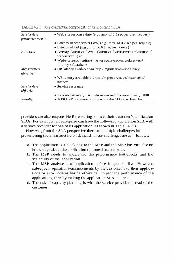
TABLE 4.2.3. Key contractual components of an application SLA
Service-level
parameter metric
● Web site response time (e.g., max of 3.5 sec per user request)
● Latency of web server (WS) (e.g., max of 0.2 sec per request)
● Latency of DB (e.g., max of 0.5 sec per query)
Function ● Average latency of WS = (latency of web server 1 +latency of
web server 2 ) /2 ● Websiteresponsetime= Averagelatencyofwebserver+
latency ofdatabase
Measurement
directive
Service-level
objective
● DB latency available via http://mgmtserver/em/latency
● WS latency available via http://mgmtserver/ws/instanceno/
latency
● Service assurance
● website latency, 1sec whenconcurrent connection, 1000
Penalty ● 1000 USD for every minute while the SLO was breached
providers are also responsible for ensuring to meet their customer’s application
SLOs. For example, an enterprise can have the following application SLA with
a service provider for one of its application, as shown in Table 4.2.3.
However, from the SLA perspective there are multiple challenges for
provisioning the infrastructure on demand. These challenges are as follows:
a. The application is a black box to the MSP and the MSP has virtually no
knowledge about the application runtime characteristics.
b. The MSP needs to understand the performance bottlenecks and the
scalability of the application.
c. The MSP analyzes the application before it goes on-live. However,
subsequent operations/enhancements by the customer’s to their applica-
tions or auto updates beside others can impact the performance of the
applications, thereby making the application SLA at risk.
d. The risk of capacity planning is with the service provider instead of the
customer.

LIFE CYCLE OF SLA
Each SLA goes through a sequence of steps starting from identification of terms and
conditions, activation and monitoring of the stated terms and conditions, and eventual
termination of contract once the hosting relationship ceases to exist. Such a sequence of
steps is called SLA life cycle and consists of the following five phases:
1. Contract definition
2. Publishing and discovery
3. Negotiation
4. Operationalization
5. De-commissioning
Here, we explain in detail each of these phases of SLA life cycle.
Contract Definition. Generally, service providers define a set of service offerings and
corresponding SLAs using standard templates.
Publication and Discovery. Service provider advertises these base service offerings
through standard publication media, and the customers should be able to locate the service
provider by searching the catalog.
Negotiation. Once the customer has discovered a service provider who can meet their
application hosting need, the SLA terms and conditions needs to be mutually agreed upon
before signing the agreement for hosting the application.
Operationalization. SLA operation consists of SLA monitoring, SLA ac- counting, and
SLA enforcement. SLA monitoring involves measuring parameter values and calculating
the metrics defined as a part of SLA and determining the deviations.
De-commissioning. SLA decommissioning involves termination of all activ- ities
performed under a particular SLA when the hosting relationship between the service
provider and the service consumer has ended.
SLA MANAGEMENT IN CLOUD
SLA management of applications hosted on cloud platforms involves five phases.
1. Feasibility
2. On-boarding
3. Pre-production
4. Production
5. Termination
Different activities performed under each of these phases are shown in Figure 4.2.7. These
activities are explained in detail in the following subsections.

Feasibility Analysis
MSP conducts the feasibility study of hosting an application on their cloud platforms. This
study involves three kinds of feasibility: (1) technical feasibility, infrastructure feasibility,
and (3) financial feasibility. The technical feasibility of an application implies determining
the following:
Application Lifecycle through Service Provider Platform
Obtain customer app Perform Technical
feasibility
Perform financial
feasibility
Package application Performance analysis
Estimate cost for each
SLA
Identify possible SLAs
SLA acceptable to
customer?
Cost is acceptable to
customer?
Create/recreate policies (BP/
OP/PP) for each of the SLA
Validated policies wrt to
SLAs
Stage the app to pre-prod env
Customer validation of app
against SLA
Choose different SLA?
Stage the app to prod env and Repeated SLA
made live SLA violation?
Customer request for new/
modification of SLA
violation?
Decline application
Pro
du
ctio
n
Pre
-Pro
du
ctio
n
On
bo
ard
ing
F
easi
bil
ity A
nal
ysi
s

Rollback the app from prod env Transfer files to customer
Application cease
FIGURE 4.2.7. Flowchart of the SLA management in cloud.
1. Ability of an application to scale out.
2. Compatibility of the application with the cloud platform being used
within the MSP’s data center.
3. The need and availability of a specific hardware and software required for
hosting and running of the application.
4. Preliminary information about the application performance and whether
they can be met by the MSP.
Performing the infrastructure feasibility involves determining the availability of
infrastructural resources in sufficient quantity so that the projected demands
of the application can be met.
On-Boarding of Application
Once the customer and the MSP agree in principle to host the application based
on the findings of the feasibility study, the application is moved from the
customer servers to the hosting platform.The application is accessible to its end
users only after the on- boarding activity is completed.
On-boarding activity consists of the following steps:
a. Packing of the application for deploying on physical or virtual environ-
ments. Application packaging is the process of creating deployable
components on the hosting platform (could be physical or virtual).
Open Virtualization Format (OVF) standard is used for packaging the
application for cloud platform .
b. The packaged application is executed directly on the physical servers to
capture and analyze the application performance characteristics.
c. The application is executed on a virtualized platform and the application
performance characteristics are noted again.
d. Based on the measured performance characteristics, different possible
SLAs are identified. The resources required and the costs involved for
each SLA are also computed.
e. Once the customer agrees to the set of SLOs and the cost, the MSP starts
creating different policies required by the data center for automated
management of the application.These policies are of three types: (1)
business, (2) operational, and (3) provisioning. Business policies help
prioritize access to the resources in case of contentions. Operational
policies (OP) are represented in the following format:
Cea
se

OP 5 collection of hCondition, Actioni
Here the action could be workflow defining the sequence of actions to be
undertaken. For example, one OP is
OP 5 haveragelatencyofwebserver. 0.8sec,scale-outtheweb-servertieri
It means, if average latency of the web server is more than 0.8 sec then
automatically scale out the web-server tier.
Scale-out, scale-in, start, stop, suspend, resume are some of the examples of
provisioning actions. A provisioning policy (PP) is represented as
PP 5 collection of hRequest, Actioni
For example, a provisioning policy to start a web site consists of the following
sequence: start database server, start web-server instance 1, followed by start the
web-server instance 2, and so on.
Preproduction
Once the determination of policies is completed as discussed in previous phase,
the application is hosted in a simulated production environment. Once both
parties agree on the cost and the terms and conditions of the SLA, the customer
sign-off is obtained. On successful completion of this phase the MSP allows
the applica- tion to go on-live.
Production
In this phase, the application is made accessible to its end users under the
agreed SLA. In the case of the former, on-boarding activity is repeated to
analyze the application and its policies with respect to SLA fulfillment. In
case of the latter, a new set of policies are formulated to meet the fresh terms
and conditions of the SLA.
Termination
When the customer wishes to withdraw the hosted application and does not
wish to continue to avail the services of the MSP for managing the hosting of its
application, the termination activity is initiated.
AUTOMATED POLICY-BASED MANAGEMENT
This section explains in detail the operationalization of the “Operational” and
“Provisioning” policies defined as part of the on-boarding activity. The policies
specify the sequence of actions to be performed under different circumstances.
Operational policies specify the functional relationship between the system-
level infrastructural attributes and the business level SLA goals. attributes at
various workloads, workload compositions, and operating conditions, so that
the SLA goals are met. Figure 4.2.8 explains the importance of such a
relationship. For example, consider a three-tier web application consisting of

web server, application server, and database server. The effect of varying the
system resources (such as CPU) on the SLO, which in this case is the average
response time for customer requests, is shown in Figure 4.2.8.
20
15
10
5
20 50 90
Percentage of CPU assigned to Application Server
FIGURE 4.2.8. Performance of a multi-tier application for varied CPU allocation.
SLO
Aver
age
Res
pon
se T
ime
(sec
)

Some of the parameters often used to prioritize action and perform resource
contention resolution are:
● The SLA class (Platinum, Gold, Silver, etc.) to which the application
belongs to.
● The amount of penalty associated with SLA breach.
● Whether the application is at the threshold of breaching the SLA.
● Whether the application has already breached the SLA.
● The number of applications belonging to the same customer that has
breached SLA.
● The number of applications belonging to the same customer about to
breach SLA.
● The type of action to be performed to rectify the situation.
Priority ranking algorithms use these parameters to derive scores. These
scores are used to rank each of the actions that contend for the same resources.
Actions having high scores get higher priority and hence, receive access to the
contended resources.
Furthermore, automatic operationalization of these policies consists of a set
of components as shown in Figure 4.2.9. The basic functionality of these
components is described below:
1. Prioritization Engine. Requests from different customers’ web applica-
tions contending for the same resource are identified, and accordingly
their execution is prioritized.
2. Provisioning Engine. Every user request of an application will be enacted
by the system.
3. Rules Engine. The operation policy defines a sequence of actions to be
enacted under different conditions/trigger points.
4. Monitoring System. Monitoring system collects the defined metrics in
SLA. These metrics are used for monitoring resource failures, evaluating
operational policies, and auditing and billing purpose.
5. Auditing. The adherence to the predefined SLA needs to be monitored
and recorded. It is essential to monitor the compliance of SLA because

Ap
p1
FIGURE 4.2.9. Component diagram of policy-based automated management system.
any noncompliance leads to strict penalties. The audit report forms the basis for
strategizing and long-term planning for the MSP.
6. Accounting/Billing System. Based on the payment model, chargebacks could be
made based on the resource utilized by the process during the operation. The fixed
cost and recurring costs are computed and billed accordingly.
The interactions among these components are shown in Figure 4.2.9 and described below.
Alternatively, the monitoring system can interact with the rules engine
through an optimization engine, as shown in Figure 4.2.10. The following
example highlights the importance of the optimization engine within a policy
based management system .
Assume an initial assignment of seven virtual machines (VM) to the three
physical machines (PM) at time t1 as shown in Figure 4.2.11.
«subsystem»
Customer Access Layer
«subsystem»
System Administrator
Dashboard
«subsystem»
Authentication and
Authorization
«subsystem»
Access Layer
«subsystem»
Accounting/Billing
System
«subsystem»
Auditing
«subsystem»
Monitoring System
«subsystem»
Prioritization
Engine
«subsystem»
Provisioning
Engine
«subsystem»
Rules Engine
«subsystem»
VM Provisioning
«subsystem»
Bare Metal
Provisioning
«subsystem»
Storage Manager
«subsystem»
NW Manager
«subsystem»
Data Center

Engine Engine Engine System
PM0 PM1 PM3
FIGURE 4.2.10. Importance of optimization in the policy-based management system.
A
pp
1
Ap
p2
VM0 VM1
VMM
A
pp
1
Ap
p2
VM0 VM1 VMM
A
pp
1
Ap
p2
VM0 VM1
VMM
VM0
VMM

Similarly, at time t1 the CPU and memory requirements of VM4, VM5, and VM6
on PMB are 20, 10, 40 and 20, 40, 20, respectively. VM7 only consumes 20%
of CPU and 20% of memory on PMC. Thus, PMB and PMC are underloaded but
PMA is overloaded. Assume VM1 is the cause of the overload situation in
PMA.
CPU
Mem
CPU
Mem
FIGURE 4.2.11. (a) Initial configuration of the VMs and the PMs at time t1. (b)
Configuration resulting from event-based migration of VM1 at time t1. (c) Resource
requirement situation at time t2 . t1. (d) Configuration resulting from “event-based”
migration of VM4 at time t2 . t1. (e) Alternate configuration resulting from optimiza-
tion-based migration at time t2 . t1.
A
2 3
CPU 40 20
Mem 10 40
4
B
5
6
20 10 40
20 40 20
7
C
1
20 40
20 20
A
2 3
CPU 40 20
Mem 10 40
4
B
5
6
20 10 40
20 40 20
7
C
1
20 40
20 20
A
2 3
CPU 40 20
Mem 10 40
B
5
6
10 40
40 20
7
C
1
4
20 40 20
20 20 40
1
A
2
3
40 40 20
20 10 40
4
B
5
6
20 10 40
20 40 20
C
7
20 20
1
A
2
3
40 40 20
20 10 40
4
B
5
6
20 10 40
20 40 20
C
7
20 20

In the above scenario, event-based migration will result in migration of
VM1 out of PMA to PMC. Furthermore, consider that at time t2 (t2 . t1),
PMB is overloaded as the memory requirement of VM4 increases to 40.
Consequently, an event-based scheme results in migration of VM4 to PMC. At
time t3 (t3 . t2), a new VM, VM8, with CPU and memory requirements of 70
each, needs to be allocated to one of the PMs; then a new PM, PMD, needs to
be switched on for hosting it. In such a scenario, VM8 cannot be hosted on any
of the three existing PMs: PMA, PMB, and PMC. However, assume that the
duration of the time window t2 - t1 is such that the QoS and SLA violations due
to the continued hosting of VM1 on PMA are well within the permissible limits.
In such a case, the migration of both VMs—VM1 to PMB and VM4 to PMA—
at time t2 ensures lesser number of PM are switched on. This results in a global
resource assignment that may be better than local resource management.
PERFORMANCE PREDICTION FOR HPC ON CLOUDS
INTRODUCTION
High-performance computing (HPC) is one of the contexts in which the
adoption of the cloud computing paradigm is debated.
As outlined in other chapters of this book, cloud computing may be
exploited at three different levels: IaaS (Infrastructure as a Service), PaaS
(Platform as a Service), and AaaS (Application as a Service). In one way or
another, all of them can be useful for HPC. However, nowadays the most
common solution is the adoption of the IaaS paradigm. IaaS lets users run
applications on fast pay-per-use machines they don’t want to buy, to manage,
or to maintain. Furthermore, the total computational power can be easily
increased (by additional charge). For the sporadic HPC user, this solution is
undoubtedly attractive: no investment in rapidly-obsolescing machines, no
power and cooling nightmares, and no system software updates.
At the state of the art, there exist many solutions for building up a cloud
environment. VMWare cloud OS is integrated in the VMWare virtualization
solutions. Opennebula [4, 26], Enomaly , and Eucalyptus are open-source
software layers that provide a service-oriented interface on the top of existing
virtual engines (mainly, VMWare and Xen). Virtual workspaces [7, 16, 27], and
related projects (Nimbus, Kupa, WISPY) build up the service-oriented inter-
face for the virtual engines by exploiting a grid infrastructure (see Section 4.3.2
for further details).
Another source of confusion for most users is the relationship between
clouds and grids. But this is obtained following two different approaches:
centralized for clouds and distributed for grids. It is easy to find on the net
many open (and often useless) discussions comparing the two paradigms. In
this chapter we will not deal further with the problem, limiting ourselves to
discuss the profitability of the two paradigms in the HPC context and to point
out the possibility to integrate both of them in a unified view.
Many applications have strict requirements for their execution
environments. Often the applications’ environment requirements are mutually
incompatible, and it is not reasonable to modify or to re-install system software
on-the-fly to make applications work. Moreover, partitioning the computing

hardware into closed environments with different characteristics is not
decidedly an efficient solution.
In light of the above, it is reasonable to think that, notwithstanding the
inevitable performance loss, cloud techniques will progressively spread into
HPC environments. As an example, Rocks, the widely used Linux distribution
for HPC clusters, provides support for virtual clusters starting from release 5.1 .
As pointed out above, the performance problem is hard due to the intrinsically
“intangible” and flexible nature of cloud systems. This makes difficult (and
maybe useless) to compare the performance of a given application that executes
in two different virtual environments received from a cloud. So, given the
extreme simplicity to ask from a cloud for additional computing resources
(with additional costs), it is almost impossible to make a choice that maximizes
the performance/cost ratio.
The presentation is organized as follows: The next section (4.3.2) introduces
the fundamentals of cloud computing paradigm applied to HPC, aiming at
defining the concepts and terminology concerning virtual clusters. Section
instead focuses on the relationship between grid and cloud, highlighting
their similarities and differences, the opportunity of their integration, and
the approaches proposed to this end. Section 4.3.4 focuses on
performance-related problems, which affect the adoption of cloud
computing for HPC, pointing out the need for methods, techniques, and
tools for performance prediction of clouds. The final section (4.3.5)
presents our conclusions.
BACKGROUND
As outlined in the introduction, the main question related to the adoption of
the cloud paradigm in HPC is related to the evaluation (and, possibly, to the
reduction) ofpossibleperformancelossescomparedtophysical HPChardware.
In clouds, performance penalties may appear at two different levels:
● Virtual Engine (VE). These are related to the performance loss introduced
by the virtualization mechanism. They are strictly related to the VE
technology adopted.
● Cloud Environment (CE). These are the losses introduced at a higher level
by the cloud environment, and they are mainly due to overheads and to
the sharing of computing and communication resources.
Additional considerations on the cloud hardware and its impact on the
performance of HPC applications will be presented in Section 4.3.3.
VFE
VN
VN
VN
VFE
VN
VN
…
VN
VFE
VN
VN
…
VN
FE PN PN PN
FE PN PN … PN
…
VLAN
VLAN
VLAN
NETWORK NETWORK

FIGURE 4.3.1. Physical and virtual cluster.
The configuration and performance analysis of virtual clusters poses
problems that are considerably more complex than those involved in the
use of physical clusters. The objective of this section is to present the main
problems and to introduce a clear and sound terminology, which is still lacking
in the literature.
A traditional cluster—that is, a physical cluster—can be schematized as in
Figure 4.3.1. It is essentially made up of a front-end (typically used only for
administration purposes, often the only node with a public IP address) and a
number of (physical) processing nodes. These are, turn, provided with a single
CPU or with multiple CPUs sharing a common memory and I/O resources. The
multiple CPUs may be multiple cores on a single processor chip, a traditional
single-core CPUs working in SMP mode, a “fictitious” CPU obtained by
hyperthreading, or a mixture of all the above.
A physical cluster can execute multiple jobs in parallel, by assigning to every
job a subset of the total number of CPUs. Usually the choice is to use non-
overlapping subsets of CPUs, in order to avoid processor sharing among
multiple jobs. But, even doing so, the interconnection network (and the front-
end) are inevitably shared.
This may, or may not, introduce significant overheads, depending on the
type of computations and their communication requirements and, above all, on
the characteristics of the interconnect. Anyway, very often this overhead is
tolerable.
A parallel application running in a physical cluster is composed of processes.
To exploit all the available computing resources, the application should use at
least a number of processes equal to the number of available CPUs (or, in the
case of concurrent jobs, equal to the number of CPU exclusively reserved for
the job). Redundant application decompositions (i.e., applications made up of
a number of processes higher than the number of CPUs) are possible and, in
some cases, they may even be more efficient.
The main problem with physical clusters is that all jobs running on the cluster,
whether concurrent or non-concurrent, have to share the same operating system
(OS), the system and application libraries, and the operating
environment (system applications and tools). The frequently recurring
requirements for mutually exclusive or incompatible libraries and support
software make physical cluster management a nightmare for system
administrators.
Basically, a virtual cluster is made up of a virtual front-end and a number of
virtual nodes (see Figure 4.3.1). Virtual front-ends are obtained by virtualiza-
tion of a physical front-end machine, and virtual nodes are obtained by
virtualization of physical processing nodes.
Even if, strictly speaking, in a virtual cluster the front-end could be
virtualized as compute nodes, a simpler and less resource-demanding solution
is to use a physical front-end. Both with physical or virtual front-ends, virtual
cluster may have an execution environment of its own (OS, libraries, tools, etc.)
that is loaded and initialized when the cluster is created. The advantages of
cluster virtualization are clear: Every application can set up a proper execution
environment, which does not interfere with all other applications and virtual

clusters running on the hardware. Moreover, the network traffic of every
virtual cluster is encapsulated in a separate VLAN. However, most likely all
VLANs will share the physical network resources.
As shown in Figure 4.3.1, every virtual processing node can host one or
several virtual machines (VMs), each running a private OS instance. These may
belong to the same or to different virtual clusters. At least in theory, the number
of VMs is limited only by resource consumption (typically, physical memory).
In turn, each VM is provided with several virtual CPUs (VCPUs). A virtual
machine manager running in every node makes it possible to share the physical
CPUs among the VCPUs defined on the node (which may belong to a single
virtual cluster or to several virtual clusters). Typically, it is possible to define
VCPU affinity and to force every VCPU to run on a subset of the physical
CPUs available.
It is worth noting that, given a physical node provided with n CPUs, there
are two possibilities to exploit all the computing resources available:
● Using n VMs (each running its OS instance) with one, or even several,
VCPUs;
● Using a single VM with at least n VCPUs.
On the other hand, the use in a node of v VCPUs, with v . n, whether in a
single or in multiple VMs, leads to a fictitious multiplication of computing
resources. In nodes where CPU resources are multiplied, the virtual clusters
not only share memory, communication hardware, and the virtual machine
manager, but also share CPU cycles, with a more direct effect on overall
computing performance.
GRID AND CLOUD
“Grid vs Cloud” is the title of an incredible number of recent Web blogs and
articles in on-line forums and magazines, where many HPC users express their
own opinion on the relationship between the two paradigms [11, 28, 29, 40].
Cloud is simply presented, by its supporters, as an evolution of the grid. Some
consider grids and clouds as alternative options to do the same thing in a different
way. However, there are very few clouds on which one can build, test, or run
compute-intensive applications. In fact it still necessary to deal with some open
issues. One is when, in term of performance, a cloud is better than a grid to run a
specific application. Another problem to be addressed concerns the effort to port
a grid application to a cloud. In the following it will be discussed how these and
other arguments suggest that we investigate the integration of grids and clouds to
improve the exploitation of computing resources in HPC.
Grid and Cloud as Alternatives
Both grid and cloud are technologies that have been conceived to provide users
with handy computing resources according to their specific requirements.
Grid was designed with a bottom-up approach [9, 30, 31, 39]. Its goal is to
share a hardware or a software among different organizations by means of
common protocols and policies. The idea is to deploy interoperable services in
order to allow the access to physical resources (CPU, memory, mass storage,

etc.) and to available software utilities. Users get access to a real machine. Grid
resources are administrated by their owners. Authorized users can invoke grid
services on remote machines without paying and without service level guaran-
tees. A grid middleware provides a set of API (actually services) to program a
heterogeneous, geographically distributed system.
On the other hand, cloud technology was designed using a top-down
approach. It aims at providing its users with a specific high-level functionality:
a storage, a computing platform, a specialized service. They get virtual
resources from the cloud. The underlying hardware/software infrastructure is
not exposed. The only information the user needs to know is the quality of
service (QoS) of the services he is paying for. Bandwidth, computing power,
and storage represent parameters that are used for specifying the QoS and for
billing. Cloud users ask for a high-level functionality (service, platform,
infrastructure), pay for it, and become owners of a virtual machine. From a
technological point of view, virtualization is exploited to build an insulated
environment, which is configured to meet users’ requirements and is exploited
for easy reconfiguration and backup. A single enterprise is the owner of the
cloud platform (software and underlying hardware), whereas customers be-
come owners of the virtual resources they pay for.
Cloud supporters claim that the cloud is easy to be used [9], is scalable , and
always gives users exactly what they want. On the other hand, grid is difficult
to be used, does not give performance guarantees, is used by narrow
communities of scientists to solve specific problems, and does not actually
support interoperability [9].
Grid fans answer that grid users do not need a credit card, that around
the world there are many examples of successful projects, and that a

great number of computing nodes connected across the net execute large-
scale scientific applications, addressing problems that could not be solved
otherwise. Grid users can use a reduced set of functionalities and can develop
simple applications, or they can get, theoretically, an infinite amount of
resources.
As always, truth is in the middle. Some users prefer to pay since they need a
specific service with strict requirements and require a guaranteed QoS. Cloud
can provide this. Many users of the scientific community look for some sort of
supercomputing architecture to solve intensive computations that process a
huge amount of data, and they do not care about getting a guaranteed
performance level. The grid can provide it. But, even on this last point, there
are divergent opinions.
Grid and Cloud Integration
To understand why grids and clouds should be integrated, we have to start by
considering what the users want and what these two technologies can provide.
Then we can try to understand how cloud and grid can complement each other
and why their integration is the goal of intensive research activities . We know
that a supercomputer runs faster than a virtualized resource. For example, a
LU benchmark on EC2 (the cloud platform provided by Amazon) runs slower,
and some overhead is added to start VMs [13]. On the other hand, the
probability to execute an application in fixed time on a grid resource depends
on many parameters and cannot be guaranteed. As experimented in Foster [13],
if 400 msec is the time that an EC2 requires to execute an LU benchmark, then
the probability of obtaining a grid resource in less that 400 msec is very low
(34%), even if the same benchmark can take less than 100 msec to complete.
If you want to get your results as soon as possible, you are adopting the
cloud end-user perspective. If you want to look for the optimum resources that
solve the problem, overcoming the boundaries of a single enterprise, you are
using the grid perspective that aims at optimizing resources sharing and system
utilization.
The integration of cloud and grid, or at least their integrated utilization, has
been proposed since there is a trade-off between application turnaround and
system utilization, and sometimes it is useful to choose the right compromise
between them.
Some issues to be investigated have been pointed out:
● Integration of virtualization into existing e-infrastructures
● Deployment of grid services on top of virtual infrastructures
● Integration of cloud-base services in e-infrastructures
● Promotion of open-source components to build clouds
● Grid technology for cloud federation

In light of the above, the integration of the two environments is a debated issue
[9]. At the state of the art, two main approaches have been proposed:
● Grid on Cloud. A cloud IaaS (Infrastructure as a Service) approach is
adopted to build up and to manage a flexible grid system . Doing so, the
grid middleware runs on a virtual machine. Hence the main drawback of
this approach is performance. Virtualization inevitably entails perfor-
mance losses as compared to the direct use of physical resources.
● Cloud on Grid: The stable grid infrastructure is exploited to build up a
cloud environment. This solution is usually preferred [7, 16] because the
cloud approach mitigates the inherent complexity of the grid. In this case,
a set of grid services is offered to manage (create, migrate, etc.) virtual
machines. The use of Globus workspaces , along with a set of grid
services for the Globus Toolkit 4, is the prominent solution, as in the
Nimbus project .
The integration could simplify the task of the HPC user to select, to configure,
and to manage resources according to the application requirements. It adds
flexibility to exploit available resources, but both of the above-presented
approaches have serious problems for overall system management, due to the
complexity of the resulting architectures. Performance prediction, application
tuning, and benchmarking are some of the relevant activities that become
critical and that cannot be performed in the absence of performance evaluation
of clouds.
HPC IN THE CLOUD: PERFORMANCE-RELATED ISSUES
This section will discuss the issues linked to the adoption of the cloud paradigm
in the HPC context. In particular, we will focus on three different issues:
1. The difference between typical HPC paradigms and those of current
cloud environments, especially in terms of performance evaluation.
2. A comparison of the two approaches in order to point out their
advantages and drawbacks, as far as performance is concerned.
3. New performance evaluation techniques and tools to support HPC in
cloud systems.
As outlined in the previous sections, the adoption of the cloud paradigm for
HPC is a flexible way to deploy (virtual) clusters dedicated to execute HPC
applications. The switch from a physical to a virtual cluster is completely
transparent for the majority of HPC users, who have just terminal access to the
cluster and limit themselves to “launch” their tasks.
The first and well-known difference between HPC and cloud environments
is the different economic approach: (a) buy-and-maintain for HPC and

(b) pay-per-use in cloud systems. In the latter, every time that a task is started,
the user will be charged for the used resources. But it is very hard to know in
advance which will be the resource usage and hence the cost. On the other hand,
even if the global expense for a physical cluster is higher, once the system has
been acquired, all the costs are fixed and predictable (in fact, they are so until
the system is not faulty). It would be great to predict, albeit approximately, the
resource usage of a target application in a cloud, in order to estimate the cost of
its execution.
These two issues above are strictly related, and a performance problem
becomes an economic problem. Let us assume that a given application is well-
optimized for a physical cluster. If it behaves on a virtual cluster as on the
physical one, it will use the cloud resources in an efficient way, and its execution
will be relatively cheap. This is not so trivial as it may seem, as the pay-per-use
paradigm commonly used in commercial clouds (see Table 4.3.1) charges the
user for virtual cluster up-time, not for CPU usage. Almost surprisingly, this
means that processor idle time has a cost for cloud users.
For clarity’s sake, it is worth presenting a simple but interesting example
regarding performance and cost. Let us consider two different virtual clusters
with two and four nodes, respectively. Let us assume that the application is
well-optimized and that, at least for a small number of processors, it gets linear
speed-up. The target application will be executed in two hours in the first cluster
and in one hour in the second one. Let the execution cost be X dollars per hour
per machine instance (virtual node). This is similar to the charging scheme of
EC2. The total cost is given by
hcost per hour per instancei m hnumberofinstancesi m hhoursi
In the first case (two-node cluster) the cost will be X*2*2, whereas in the second
one it will be X*1*4. It turns out that the two configurations have the same cost
for the final user, even if the first execution is slower than the second. Now if we
consider an application that is not well-optimized and has a speed-up less than
the ideal one, the running time on the large virtual cluster will be longer than
two hours; as a consequence, the cost of the run of the second virtual cluster
TABLE 4.3.1. Example of Cost Criteria
Cloud Provide r Index Description
Amazon $/hour Cost (in $) per hour of activity of the virtual
machines.
Amazon $/GB Cost (in $) per Gigabyte transferred outside
the cloud zone (transfers inside the same
zone have no price)
GoGrid $*RAM/hour Cost (in $) by RAM memory allocated per
hour

will be higher than that on the small one. In conclusion: In clouds, performance
counts two times. Low performance means not only long waiting times, but
also high costs. The use of alternative cost factors (e.g., the RAM memory
allocated, as for GoGrid in Table 4.3.1) leads to completely different considera-
tions and requires different application optimizations to reduce the final cost of
execution.
In light of the above, it is clear that the typical HPC user would like to know
how long his application will run on the target cluster and which configuration
has the highest performance/cost ratio. The advanced user, on the other hand,
would also know if there is a way to optimize its application so as to reduce the
cost of its run without sacrificing performance. The high-end user, who cares
more for performance than for the cost to be sustained, would like instead to
know how to choose the best configuration to maximize the performance of his
application. In other words, in the cloud world the hardware configuration is
not fixed, and it is not the starting point for optimization decisions. Config-
urations can be easily changed in order to fit the user needs. All the three classes
of users should resort to performance analysis and prediction tools. But,
unfortunately, prediction tools for virtual environments are not available, and
the literature presents only partial results on the performance analysis of such
systems.
An additional consequence of the different way that HPC users exploit a
virtual cluster is that the cloud concept makes very different the system
dimensioning—that is, the choice of the system configuration fit for the user
purposes (cost, maximum response time, etc.). An HPC machine is chosen and
acquired, aiming to be at the top of available technology (under inevitable
money constraints) and to be able to sustain the highest system usage that may
eventually be required. This can be measured in terms of GFLOPS, in terms of
number of runnable jobs, or by other indexes depending on the HPC
applications that will be actually executed. In other words, the dimensioning
is made by considering the peak system usage. It takes place at system
acquisition time, by examining the machine specifications or by assembling it
using hardware components of known performance. In this phase, simple and
global performance indexes are used (e.g., bandwidth and latency for the
interconnect, peak FLOPS for the computing nodes, etc.).
In clouds, instead, the system must be dimensioned by finding out an
optimal trade-off between application performance and used resources. As
mentioned above, the optimality is a concept that is fairly different, depending
on the class of users. Someone would like to obtain high performance at any
cost, whereas others would privilege economic factors. In any case, as the
choice of the system is not done once and for all, the dimensioning of the virtual
clusters takes place every time the HPC applications have to be executed on
new datasets. In clouds, the system dimensioning is a task under the control of
the user, not of the system administrator. This completely changes the scenario
and makes the dimensioning a complex activity, eager for performance data
and indexes that can be measured fairly easily in the HPC world on physical

TABLE 4.3.2. Differences Between “Classical” HPC and HPC in Cloud Environments
Problem HPC HPC in Clouds
Cost Buy-and-maintain
paradigm
Pay-per-use paradigm
Performance
optimization
Tuning of the application
to the hardware
Joint tuning of application
and system
System dimensioning At system acquisition time,
using global performance
indexes under system ad-
ministrator control
At every application
execution, using application
oriented performance
indexes, under user control
systems, but that are not generally available for complex and rapidly changing
systems as virtual clusters.
Table 4.3.2 summarizes the differences between HPC classical
environments and HPC in clouds. To summarize the above discussion, in
systems (the clouds) where the availability of performance data is crucial to
know how fast your applications will run and how much you will pay, there is
great uncertainty about what to measure and how to measure, and there are
great difficulties when attempting to interpret the meaning of measured data.
HPC Systems and HPC on Clouds: A Performance
Comparison
The second step of our analysis is a performance comparison between classical
HPC systems and the new cloud paradigm. This will make it possible to point
out the advantages and disadvantages of the two approaches and will enable us
to understand if and when clouds can be useful for HPC.
The performance characterization of HPC systems is usually carried out by
executing benchmarks. However, the only ones that make measurements of
virtual clusters at different levels and provide available results in the literature
[18—22, 33, 34, 36] are the following:
● The LINPACK benchmark, a so-called kernel benchmark, which aims at
measuring the peak performance (in FLOPSs) of the target environment.
● The NAS Parallel Benchmarks (NPB), a set of eight programs designed to
help to evaluate the performance of parallel supercomputers, derived from
computational fluid dynamics (CFD) applications and consisting of five
kernels and three pseudo-applications. As performance index, together
with FLOPS, it measures response time, network bandwidth usage, and
latency.
● mpptest, a microbenchmark that measures the performance of some of the
basic MPI message passing routines in a variety of different conditions. It
measures (average) response time, network bandwidth usage and latency.

When these benchmarks are executed on physical machines (whether clusters
or other types of parallel hardware), they give a coarse-level indication of the
system potentialities. In the HPC world, these benchmarks are of common use
and widely diffused, but their utility is limited. Users usually have an in-depth
knowledge of the target hardware used for executing their applications, and a
comparison between two different (physical) clusters makes sense only for
Top500 classification or when they are acquired. HPC users usually outline the
potentiality and the main features of their system through (a) a brief description
of the hardware and (b) a few performance indexes obtained using some of the
above-presented benchmarks. In any case, these descriptions are considered
useless for application performance optimization, because they only aim at
providing a rough classification of the hardware.
Recently, the benchmarking technique has been adopted in a similar way,
tackling also the problem of the utility of the cloud paradigm for scientific
applications. In particular, the papers focusing on the development of applica-
tions executed in virtual clusters propose the use of a few benchmarks to outline
the hardware potentialities [22, 23]. These results are of little interest for our
comparison. On the other hand, papers that present comparisons between
virtual and physical clusters [18, 20—22, 36, 37] use benchmarks to find out the
limits of cloud environments, as discussed below. In the following, we will focus
on these results.
We can start our analysis from benchmark-based comparison of virtual
clusters and physical HPC systems. In the literature there are results on all three
types of benchmarks mentioned above, even if the only cloud provider
considered is Amazon EC2 (there are also results on private clusters, but in
those cases the analysis focuses on virtual engine level and neglects the effects of
the cloud environment, and so it is outside the scope of this chapter).
Napper and Bientinesi [20] and Ostermann et al. [21] adopted the LINPACK
benchmark, measuring the GFLOPS provided by virtual clusters composed of
Amazon EC2 virtual machines. Both studies point out that the values obtained
in the VCs are an order of magnitude lower than equivalent solutions on physical
clusters. The best result found in the literature is about 176 GFLOPS, to be
compared to 37.64 TFLOPS of the last (worst) machine in Top500 list. Even if it
is reasonable that VCs peak performances are far from the supercomputer ones,
it is worth noting that the GFLOPS tends to decrease (being fixed the memory
load) when the number of nodes increases. In other words, virtual clusters are
not so efficient as physical clusters, at least for this benchmark. As shown later,
the main cause of this behavior is the inadequate internal interconnect.
An analysis by real-world codes, using the NPB (NAS parallel benchmark)
benchmark suite, was proposed in Walker , Ostermann et al. [21]. NPBs are a
collection of MPI-based HPC applications. The suite is organized so as to
stress different aspects of an HPC systems—for example, computation, com-
munication, or I/O.
Walker compared a virtual EC2 cluster to a physical cluster composed of
TeraGrid machines with similar hardware configuration (i.e., the hardware

under the virtual cluster was the same adopted by the physical cluster). This
comparison pointed out that the overheads introduced by the virtualization
layer and the cloud environment level were fairly high. It should be noted that
Walker adopted for his analysis two virtual clusters made up of a very limited
number of nodes (two and four). But, even for such small systems, the
applications did not scale well with the number of nodes.
The last kind of benchmark widely adopted in the literature is the MPI kernel
benchmark, which measures response time, bandwidth, and latency for MPI
communication primitives. These tests, proposed by almost all the authors who
tried to run scientific applications on cloud-based virtual clusters, are coherent
with the results presented above. In all the cases in the literature, bandwidth
and, above all, latency have unacceptable values for HPC applications.
In the literature, at the best of the authors’ knowledge, there are currently no
other examples of virtual cluster benchmarking, even if the ongoing diffusion of
the paradigm will lead probably to a fast growth of this kind of results in the
next years. As mentioned above, the benchmarking technique is able to put in
evidence the main drawback linked to the adoption of cloud systems for HPC:
the unsatisfactory performance of the network connection between virtual
clusters. In any case, the performance offered by virtual clusters is not
comparable to the one offered by physical clusters.
Even if the results briefly reported above are of great interest and can be of
help to get insight on the problem, they do not take into account the differences
between HPC machines and HPC in the cloud, which we have summarized at
the start of this section. Stated another way, the mentioned analyses simply
measure global performance indexes. But the scenario can drastically change if
different performance indexes are measured.
Just to start, the application response time is perhaps the performance index
of great importance in a cloud context. In fact, it is a measurement of interest
for the final user and, above all, has a direct impact on the cost of the
applicationexecution. Aninterestingconsiderationlinkedtoresponsetimewas
proposed by Ian Foster in his blog . The overall application response time
(RT) is given by the formula RT 5 h job submission timei 1 hexecution timei.
In common HPC environments (HPC system with batch queue, grids, etc.)
the job submission time may be fairly long (even minutes or hours, due to
necessity to get all the required computing resources together). On the other
hand, in a cloud used to run HPC workload (a virtual cluster dedicated to the
HPC user), queues (and waiting time) simply disappear. The result is that, even
if the virtual cluster may offer a much lower computational power, the final
response time may be comparable to that of (physical) HPC systems.
In order to take into account this important difference between physical and
virtual environments, Foster suggests to evaluate the response time in terms of
probability of completion, which is a stochastic function of time, and represents
the probability that the job will be completed before that time. Note that the
stochastic behavior mainly depends on the job submission time, whereas
execution time is usually a deterministic value. So in a VC the probability of

completion is a threshold function (it is zero before the value corresponding to
execution time of actual task, and one after). In a typical HPC environment,
which involves batch and queuing systems, the job submission time is stochastic
and fairly long, thus leading to a global completion time higher than the one
measured on the VC.
This phenomenon opens the way to a large adoption of the cloud approach,
at least for middle- or small-dimension HPC applications, where the computa-
tion power loss due to the use of the cloud is more tolerable. In Jha et al. [9] and
in the on-line discussion [13] it is well shown that the cloud approach could be
very interesting for substituting the ecosystem of HPC clusters that are usually
adopted for solving middle-dimension problems. This is a context in which the
grid paradigm was never largely adopted because of the high startup overhead.
Supporting HPC in the Cloud
The above-presented analysis shows how the cloud approach has good chances to
be widely adopted for HPC [32, 35, 38], even if there are limits one should be aware
of, before trying to switch to virtualized systems. Moreover, the differences
between “physical computing” and “virtual computing,” along with their impact
on performance evaluation, clearly show that common performance indexes,
techniques, and tools for performance analysis and prediction should be suitably
adapted to comply with the new computing paradigm.
To support HPC applications, a fundamental requirement from a cloud
provider is that an adequate service-level agreement (SLA) is granted. For HPC
applications, the SLA should be different from the ones currently offered for
the most common uses of cloud systems, oriented at transactional Web
applications. The SLA should offer guarantees useful for the HPC user to
predict his application performance behavior and hence to give formal (or semi-
formal) statements about the parameters involved. At the state of the art, cloud
providers offer their SLAs in the form of a contract (hence in natural language,
with no formal specification). Two interesting examples are Amazon EC2
(http://aws.amazon.com/ec2-sla/) and GoGrid (http://www.gogrid.com/legal/
sla.php).
The first one (Amazon) stresses fault tolerance parameters (such as service
uptime), offering guarantees about system availability. There are instead no
guarantees about network behavior (for both internal and external network),
except that it will “work” 95% of the time. Moreover, Amazon guarantees that
the virtual machine instances will run using a dedicated memory (i.e., there will
be no other VM allocated to on the physical machine using the same memory).
This statement is particularly relevant for HPC users, because it is of great help
for the performance predictability of applications.
On the other hand, GoGrid, in addition to the availability parameters, offers
a clear set of guarantees on network parameters, as shown in Table 4.3.3. This
kind of information is of great interest, even if the guaranteed network latency
(order of milliseconds) is clearly unacceptable for HPC applications. GoGrid
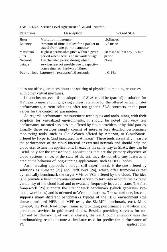
TABLE 4.3.3. Service-Level Agreement of GoGrid Network
Parameter Description GoGrid SLA
Jitter Variation in latency ,0.5msec
Latency Amount of time it takes for a packet to
travel from one point to another
,5 msec
Maximum
jitter
Network
outage
Highest permissible jitter within a given
period when there is no network outage
Unscheduled period during which IP
services are not useable due to capacity-
constraints or hardware failures
10 msec within any 15-min
period
None
Packet loss Latency in excess of 10 seconds , 0.1%
does not offer guarantees about the sharing of physical computing resources
with other virtual machines.
In conclusion, even if the adoption of SLA could be (part of) a solution for
HPC performance tuning, giving a clear reference for the offered virtual cluster
performances, current solutions offer too generic SLA contracts or too poor
values for the controlled parameters.
As regards performance measurement techniques and tools, along with their
adaption for virtualized environments, it should be noted that very few
performance-oriented services are offered by cloud providers or by third parties.
Usually these services simply consist of more or less detailed performance
monitoring tools, such as CloudWatch offered by Amazon, or CloudStatus,
offered by Hyperic (and integrated in Amazon). These tools essentially measure
the performance of the cloud internal or external network and should help the
cloud user to tune his applications. In exactly the same way as SLAs, they can be
useful only for the transactional applications that are the primary objective of
cloud systems, since, at the state of the art, they do not offer any features to
predict the behavior of long-running applications, such as HPC codes.
An interesting approach, although still experimental, is the one offered by
solutions as C-meter [21] and PerfCloud [24], which offer frameworks that
dynamically benchmark the target VMs or VCs offered by the cloud. The idea
is to provide a benchmark-on-demand service to take into account the extreme
variability of the cloud load and to evaluate frequently its actual state. The first
framework [25] supports the GrenchMark benchmark (which generates syn-
thetic workloads) and is oriented to Web applications. The second one, instead,
supports many different benchmarks typical of the HPC environment (the
above-mentioned NPB and MPP tests, the SkaMPI benchmark, etc.). More
detailed, the PerfCloud project aims at providing performance evaluation and
prediction services in grid-based clouds. Besides providing services for on-
demand benchmarking of virtual clusters, the PerfCloud framework uses the
benchmarking results to tune a simulator used for predict the performance of
PC applications.

BEST PRACTICES IN ARCHITECTING CLOUD
APPLICATIONS IN THE AWS CLOUD
INTRODUCTION
For several years, software architects have discovered and implemented several
concepts and best practices to build highly scalable applications. In today’s
“era of tera,” these concepts are even more applicable because of ever-growing
datasets, unpredictable traffic patterns, and the demand for faster response
times. This chapter will reinforce and reiterate some of these traditional
concepts and discuss how they may evolve in the context of cloud computing.
It will also discuss some unprecedented concepts, such as elasticity, that have
emerged due to the dynamic nature of the cloud.
This chapter is targeted toward cloud architects who are gearing up to move
an enterprise-class application from a fixed physical environment to a virtua-
lized cloud environment. The focus of this chapter is to highlight concepts,
principles, and best practices in creating new cloud applications or migrating
existing applications to the cloud.
BACKGROUND
As a cloud architect, it is important to understand the benefits of cloud
computing. In this section, you will learn some of the business and technical
benefits of cloud computing and different Amazon Web services (AWS)
available today. .
Business Benefits of Cloud Computing
There are some clear business benefits to building applications in the cloud. A
few of these are listed here:
Almost Zero Upfront Infrastructure Investment. If you have to build a large-
scale system, it may cost a fortune to invest in real estate, physical
security, hardware (racks, servers, routers, backup power supplies),
hardware management (power management, cooling), and operations
personnel. Because of the high upfront costs, the project would typically
require several rounds of management approvals before the project could
even get started. Now, with utility-style cloud computing, there is no fixed
cost or startup cost.

Just-in-Time Infrastructure. In the past, if your application became popular
and your systems or your infrastructure did not scale, you became a victim
of your own success. Conversely, if you invested heavily and did not get
popular, you became a victim of your failure. By deploying applications
in-the-cloud with just-in-time self-provisioning, you do not have to worry
about pre-procuring capacity for large-scale systems. This increases agility,
lowers risk, and lowers operational cost because you scale only as you grow
and only pay for what you use.
More Efficient Resource Utilization. System administrators usually worry
about procuring hardware (when they run out of capacity) and higher
infrastructure utilization (when they have excess and idle capacity). With
the cloud, they can manage resources more effectively and efficiently by
having the applications request and relinquish resources on-demand.
Usage-Based Costing. With utility-style pricing, you are billed only for the
infrastructure that has been used. You are not paying for allocated
infrastructure but instead for unused infrastructure. This adds a new
dimension to cost savings. You can see immediate cost savings (some-
times as early as your next month’s bill) when you deploy an optimization
patch to update your cloud application. For example, if a caching layer
can reduce your data requests by 70%, the savings begin to accrue
immediately and you see the reward right in the next bill. Moreover,
if you are building platforms on the top of the cloud, you can pass on
the same flexible, variable usage-based cost structure to your own
customers.
Reduced Time to Market. Parallelization is one of the great ways to speed up
processing. If one compute-intensive or data-intensive job that can be run
in parallel takes 500 hours to process on one machine, with cloud
architectures , it would be possible to spawn and launch 500 instances and
process the same job in 1 hour. Having available an elastic infrastructure
provides the application with the ability to exploit paralle- lization in a
cost-effective manner reducing time to market.
Technical Benefits of Cloud Computing
Some of the technical benefits of cloud computing includes:
Automation—“Scriptable Infrastructure”: You can create repeatable build
and deployment systems by leveraging programmable (API-driven)
infrastructure.
Auto-scaling: You can scale your applications up and down to match your
unexpected demand without any human intervention. Auto-scaling
encourages automation and drives more efficiency.
Proactive Scaling: Scale your application up and down to meet your
anticipated demand with proper planning understanding of your traffic
patterns so that you keep your costs low while scaling.
More Efficient Development Life Cycle: Production systems may be easily
cloned for use as development and test environments. Staging environ-
ments may be easily promoted to production.

Amazon
RDS
Amazon Elastic
MapReduce JobFlows
Amazon
Cloud
Front
Amazon EC2 Instances
(On-Demand, Spot, Reserved)
Amazon S3
Objects and
Buckets
EBS
Volumes Snapshots
Amazon
Virtual Private Cloud
Amazon WorldWide Physical Infrastructure
(Geographical Regions, Availability Zones, Edge Locations)
Improved Testability: Never run out of hardware for testing. Inject and
automate testing at every stage during the development process. You can
spawn up an “instant test lab” with preconfigured environments only for
the duration of testing phase.
Disaster Recovery and Business Continuity: The cloud provides a lower cost
option for maintaining a fleet of DR servers and data storage. With
the cloud, you can take advantage of geo-distribution and replicate the
environment in other location within minutes.
“Overflow” the Traffic to the Cloud: With a few clicks and effective load
balancing tactics, you can create a complete overflow-proof application
by routing excess traffic to the cloud.
Understanding the Amazon Web Services Cloud
The Amazon Web Services (AWS) cloud provides a highly reliable and scalable
infrastructure for deploying Web-scale solutions, with minimal support and
administration costs, and more flexibility than you’ve come to expect from your
own infrastructure, either on-premise or at a datacenter facility. AWS offers
variety of infrastructure services today. The diagram below will introduce you
to the AWS terminology and help you understand how your application can
interact with different Amazon Web Services (Figure 4.4.1) and how different
services interact with each other. Amazon Elastic Compute Cloud (Amazon
EC2) is a Web service that provides resizable compute capacity in the cloud.
You can bundle the operating system, application software, and associated
configuration settings into an Amazon machine image (AMI). You can then use
these AMIs to provision multiple virtualized instances as well as decommission
them using simple Web service calls to scale capacity up and down quickly, as
your capacity requirement changes. You can purchase either (a) on-demand
Auto-
Scaling
Elastic
LB
Cloud
Watch
FIGURE 4.4.1. Amazon Web Services.
Your Application
Pay
men
t: A
maz
on
FP
S/D
evP
ay
Am
azon S
imp
leD
B D
om
ains
Am
azon S
NS
To
pic
s
Am
azon S
QS
Qu
eues

instances, in which you pay for the instances by the hour, or (b) reserved
instances, in which you pay a low, one-time payment and receive a lower usage
rate to run the instance than with an on-demand instance or spot instances
where you can bid for unused capacity and further reduce your cost. Instances
can be launched in one or more geographical regions. Each region has multiple
availability zones. Availability zones are distinct locations that are engineered
to be insulated from failures in other availability zones and provide inexpen-
sive, low-latency network connectivity to other availability zones in the same
region.
Elastic IP addresses allow you to allocate a static IP address and program-
matically assign it to an instance. You can enable monitoring on an Amazon
EC2 instance using Amazon CloudWatch in order to gain visibility into
resource utilization, operational performance, and overall demand patterns
(including metrics such as CPU utilization, disk reads and writes, and network
traffic). You can create an auto-scaling group using the auto-scaling feature to
automati- cally scale your capacity on certain conditions based on metric that
Amazon CloudWatch collects. You can also distribute incoming traffic by
creating an elastic load balancer using the Elastic Load Balancing service .
Amazon Elastic Block Storage (EBS) volumes provide network-attached
persistent storage to Amazon EC2 instances. Point-in-time consistent snapshots
of EBS volumes can be created and stored on Amazon Simple Storage Service
(Amazon S3).
Amazon S3 is highly durable and distributed data store. With a simple Web
services interface, you can store and retrieve large amounts of data as objects in
buckets (containers) at any time, from anywhere on the Web using standard
HTTP verbs. Copies of objects can be distributed and cached at 14 edge
locations around the world by creating a distribution using Amazon Cloud-
Front service , a Web service for content delivery (static or streaming content).
Amazon SimpleDB[9] is a Web service that provides the core functionality of a
database—real-time lookup and simple querying of struc- tured data—without
the operational complexity. You can organize the dataset into domains and can
run queries across all of the data stored in a particular domain. Domains are
collections of items that are described by attribute—value pairs. Amazon
Relational Database Service (Amazon RDS) provides an easy way to set up,
operate, and scale a relational database in the cloud. You can launch a DB
instance and get access to a full-featured MySQL database and not worry about
common database administration tasks like backups, patch management, and so
on.
Amazon Simple Queue Service (Amazon SQS) is a reliable, highly scalable,
hosted distributed queue for storing messages as they travel between computers
and application components.
Amazon Elastic MapReduce provides a hosted Hadoop framework running
on the web-scale infrastructure of Amazon Elastic Compute Cloud (Amazon
EC2) and Amazon Simple Storage Service (Amazon S3) and allows you to create
customized JobFlows. JobFlow is a sequence of MapReduce steps.
Amazon Simple Notifications Service (Amazon SNS) provides a simple way
to notify applications or people from the cloud by creating Topics and using a

publish-subscribe protocol.
Amazon Virtual Private Cloud (Amazon VPC)[13] allows you to extend
your corporate network into a private cloud contained within AWS. Amazon
VPC uses an IPSec tunnel mode that enables you to create a secure connection
between a gateway in your data center and a gateway in AWS.
AWS also offers various payment and billing services that leverages
Amazon’s payment infrastructure.
All AWS infrastructure services offer utility-style pricing that require no long-
term commitments or contracts. For example, you pay by the hour for Amazon
EC2 instance usage and pay by the gigabyte for storage and data transfer in the
case of Amazon S3. More information about each of these services and their pay-
as-you-go pricing is available on the AWS Web site.
CLOUD CONCEPTS
The cloud reinforces some old concepts of building highly scalable Internet
architectures and introduces some new concepts that entirely change the way
applications are built and deployed. Hence, when you progress from concept to
implementation, you might get the feeling that “Everything’s changed, yet
nothing’s different.” The cloud changes several processes, pat- terns, practices,
and philosophies and reinforces some traditional service- oriented architectural
principles that you have learned because they are even more important than
before. In this section, you will see some of those new cloud concepts and
reiterated SOA concepts.
Traditional applications were built with some pre-conceived mindsets that
made economic and architectural-sense at the time they were developed. The
cloud brings some new philosophies that you need to understand, and these are
discussed below.
Building Scalable Architectures
It is critical to build a scalable architecture in order to take advantage of a
scalable infrastructure.
The cloud is designed to provide conceptually infinite scalability. However,
you cannot leverage all that scalability in infrastructure if your architecture is
not scalable. Both have to work together. You will have to identify the
monolithic components and bottlenecks in your architecture, identify the areas
where you cannot leverage the on-demand provisioning capabilities in your
architecture, and work to refactor your application in order to leverage the
scalable infrastructure and take advantage of the cloud.
Characteristics of a truly scalable application:
● Increasing resources results in a proportional increase in performance.
● A scalable service is capable of handling heterogeneity.
● A scalable service is operationally efficient.
● A scalable service is resilient.

● A scalable service should become more cost effective when it grows (cost
per unit reduces as the number of units increases).
These are things that should become an inherent part of your application; and
if you design your architecture with the above characteristics in mind, then
both your architecture and infrastructure will work together to give you the
scalability you are looking for.
Understanding Elasticity
Figure 4.4.2 illustrates the different approaches a cloud architect can take to
scale their applications to meet the demand.
Scale-Up Approach. Not worrying about the scalable application architec-
ture and investing heavily in larger and more powerful computers
(vertical scaling) to accommodate the demand. This approach usually
works to a point, but either it could cost a fortune (see “Huge capital
expenditure” in Figure 4.4.2) or the demand could outgrow capacity
before the new “big iron” is deployed (see “You just lost your customers”
in diagram).
Too much excess capacity
“Opportunity cost”
Huge capital
expenditure You just lost your customers
Predicted demand
Actual demand
Scale-up approach
Traditional scale-out approach
Automated elasticity
Time t
Automated Elasticity + Scalability
FIGURE 4.4.2. Automated elasticity.
The Traditional Scale-Out Approach. Creating an architecture that scales
horizontally and investing in infrastructure in small chunks. Most of the
businesses and large-scale Web applications follow this pattern by
distributing their application components, federating their datasets, and
employing a service-oriented design. This approach is often more effective
than a scale-up approach. However, this still requires predicting the
Infr
astr
ctu
re C
ost
$$

demand at regular intervals and then deploying infrastructure in chunks
to meet the demand. This often leads to excess capacity (“burning cash”)
and constant manual monitoring (“burning human cycles”). Moreover, it
usually does not work if the application is a victim of a viral fire (often
referred to as the Slashdot Effect ).
Note: Both approaches have initial startup costs, and both
approaches are reactive in nature.
Traditional infrastructure generally necessitates predicting the amount of
computing resources your application will use over a period of several years. If
you underestimate, your applications will not have the horsepower to handle
unexpected traffic, potentially resulting in customer dissatisfaction. If you
overestimate, you’re wasting money with superfluous resources.
The on-demand and elastic nature of the cloud approach (automated
elasticity), however, enables the infrastructure to be closely aligned (as it
expands and contracts) with the actual demand, thereby increasing overall
utilization and reducing cost.
Elasticity is one of the fundamental properties of the cloud. Elasticity is the
power to scale computing resources up and down easily and with minimal
friction. It is important to understand that elasticity will ultimately drive most
of the benefits of the cloud. As a cloud architect, you need to internalize this
concept and work it into your application architecture in order to take
maximum benefit of the cloud.
Traditionally, applications have been built for fixed, rigid, and pre-
provisioned infrastructure. Companies never had the need to provision and
install servers on a daily basis. As a result, most software architectures do not
address the rapid deployment or reduction of hardware. Since the provisioning
time and upfront investment for acquiring new resources was too high,
software architects never invested time and resources in optimizing for hard-
ware utilization. It was acceptable if the hardware on which the application is
running was underutilized. The notion of “elasticity” within an architecture
was overlooked because the idea of having new resources in minutes was not
possible.
With the cloud, this mindset needs to change. Cloud computing streamlines
the process of acquiring the necessary resources; there is no longer any need to
place orders ahead of time and to hold unused hardware captive. Instead, cloud
architects can request what they need mere minutes before they need it or
automate the procurement process, taking advantage of the vast scale and rapid
response time of the cloud. The same is applicable to releasing the unneeded or
underutilized resources when you don’t need them. If you cannot embrace the
change and implement elasticity in your application architecture, you might not
be able to take the full advantage of the cloud. As a cloud architect, you should
think creatively and think about ways you can implement elasticity in your
application. For example, infrastructure that used to run daily nightly builds
and performs regression and unit tests every night at 2:00 AM for two hours
(often termed as the “QA/Build box”) was sitting idle for rest of the day. Now,
with elastic infrastructure, one can run nightly builds on boxes that are “alive”
and being paid for only for 2 hours in the night. Likewise, an internal trouble
ticketing Web application that always used to run on peak capacity (5 servers
24 3 7 3365) to meet the demand during the day can now be provisioned to
run on-demand (five servers from 9 AM to 5 PM and two servers for 5 PM to 9 AM)
based on the traffic pattern.
Designing intelligent elastic cloud architectures, so that infrastructure runs
only when you need it, is an art in itself. Elasticity should be one of the
architectural design requirements or a system property. The questions that you
need to ask are as follows: What components or layers in my application
architecture can become elastic? What will it take to make that component
elastic? What will be the impact of implementing elasticity to my overall system
architecture?
In the next section, you will see specific techniques to implement elasticity in
your applications. To effectively leverage the cloud benefits, it is important to
architect with this mindset.
Not Fearing Constraints
When you decide to move your applications to the cloud and try to map your
system specifications to those available in the cloud, you will notice that cloud
might not have the exact specification of the resource that you have on-premise.
For example, “Cloud does not provide X amount of RAM in a server” or “My
database needs to have more IOPS than what I can get in a single instance.”
You should understand that cloud provides abstract resources that become
powerful when you combine them with the on-demand provisioning model.
You should not be afraid and constrained when using cloud resources because
it is important to understand that even if you might not get an exact replica
of your hardware in the cloud environment, you have the ability to get more of
those resources in the cloud to compensate that need.
For example, if the cloud does not provide you with exact or greater amount
of RAM in a server, try using a distributed cache like memcached or
partitioning your data across multiple servers. If your databases need more
IOPS and it does not directly map to that of the cloud, there are several
recommendations that you can choose from depending on your type of data
and use case. If it is a read-heavy application, you can distribute the read load
across a fleet of synchronized slaves. Alternatively, you can use a sharding
algorithm that routes the data where it needs to be or you can use various
database clustering solutions.
In retrospect, when you combine the on-demand provisioning capabilities
with the flexibility, you will realize that apparent constraints can actually be
broken in ways that will actually improve the scalability and overall perfor-
mance of the system.
Virtual Administration
The advent of cloud has changed the role of System Administrator to a “Virtual
System Administrator.” This simply means that daily tasks performed by these
administrators have now become even more interesting as the administrators
learn more about applications and decide what’s best for the business as a
whole. The System Administrator no longer has a need to provision servers and
install software and wire up network devices since all of that grunt work is
replaced by few clicks and command line calls. The cloud encourages automa-

tion because the infrastructure is programmable. System administrators need to
move up the technology stack and learn how to manage abstract cloud
resources using scripts.
Likewise, the role of Database Administrator is changed into a “Virtual
Database Administrator” (DBA) in which he/she manages resources through a
Web-based console, executes scripts that add new capacity programmatically if
the database hardware runs out of capacity, and automates the day-to-day
processes. The virtual DBA has to now learn new deployment methods (virtual
machine images), embrace new models (query parallelization, geo-redundancy,
and asynchronous replication [19]), rethink the architectural approach for data
(sharding [20], horizontal partitioning , federating [21]), and leverage different
storage options available in the cloud for different types of datasets. In the
traditional enterprise company, application developers may not work closely
with the network administrators and network administrators may not have a
clue about the application. As a result, several possible optimizations in the
network layer and application architecture layer are overlooked. With the
cloud, the two roles have merged into one to some extent. When architecting
future applications, companies need to encourage more cross-pollination of
knowledge between the two roles and understand that they are merging.
CLOUD BEST PRACTICES
In this section, you will learn about best practices that will help you build an
application in the cloud.
Design for Failure and Nothing Will Fail
Rule of Thumb: Be a pessimist when designing architectures in the cloud;
assume things will fail. In other words, always design, implement, and deploy
for automated recovery from failure.
In particular, assume that your hardware will fail. Assume that outages will
occur. Assume that some disaster will strike your application. Assume that you
will be slammed with more than the expected number of requests per second
some day. Assume that with time your application software will fail too. By
being a pessimist, you end up thinking about recovery strategies during design
time, which helps in designing an overall system better.
If you realize that things fail over time and incorporate that thinking into
your architecture, as well as build mechanisms to handle that failure before
disaster strikes to deal with a scalable infrastructure, you will end up creating a
fault-tolerant architecture that is optimized for the cloud.
Questions that you need to ask: What happens if a node in your system fails?
How do you recognize that failure? How do I replace that node? What kind of
scenarios do I have to plan for? What are my single points of failure? If a load
balancer is sitting in front of an array of application servers, what if that
load balancer fails? If there are master and slaves in your architecture, what if
the master node fails? How does the failover occur and how is a new slave
instantiated and brought into sync with the master?
Just like designing for hardware failure, you have to also design for software

failure. Questions that you need to ask: What happens to my application if the
dependent services changes its interface? What if downstream service times out
or returns an exception? What if the cache keys grow beyond memory limit of
an instance?
Build mechanisms to handle that failure. For example, the following
strategies can help in event of failure:
1. Haveacoherent backupandrestorestrategyforyourdataandautomateit.
2. Build process threads that resume on reboot.
3. Allow the state of the system to re-sync by reloading messages from
queues.
4. Keep preconfigured and preoptimized virtual images to support strategies
2 and 3 on launch/boot.
5. Avoid in-memory sessions or stateful user context; move that to data
stores.
Good cloud architectures should be impervious to reboots and re-launches. In
GrepTheWeb (discussed in the next section), by using a combination of
Amazon SQS and Amazon SimpleDB, the overall controller architecture is
very resilient to the types of failures listed in this section. For instance, if the
instance on which controller thread was running dies, it can be brought up and
resume the previous state as if nothing had happened. This was accomplished
by creating a preconfigured Amazon machine image, which, when launched,
dequeues all the messages from the Amazon SQS queue and reads their states
from an Amazon SimpleDB domain on reboot.
Designing with an assumption that underlying hardware will fail will prepare
you for the future when it actually fails.
This design principle will help you design operations-friendly applications,
as also highlighted in Hamilton’s paper [19]. If you can extend this principle to
proactively measure and balance load dynamically, you might be able to deal
with variance in network and disk performance that exists due to the multi-
tenant nature of the cloud.
AWS-Specific Tactics for Implementing This Best Practice
1. Failover gracefully using Elastic IPs: Elastic IP is a static IP that is
dynamically remappable. You can quickly remap and failover to
another set of servers so that your traffic is routed to the new servers.
It works great when you want to upgrade from old to new versions or
in case of hardware failures.
2. Utilize multiple availability zones: Availability zones are conceptually
like logical datacenters. By deploying your architecture to multiple
availability zones, you can ensure high availability.
3. Maintain an Amazon Machine Image so that you can restore and
clone environments very easily in a different availability zone; main-
tain multiple database slaves across availability zones and set up hot
replication.

Decouple your Components
The cloud reinforces the SOA design principle that the more loosely coupled the
components of the system, the bigger and better it scales.
The key is to build components that do not have tight dependencies on each
other, so that if one component were to die (fail), sleep (not respond), or remain
busy (slow to respond) for some reason, the other components in the system are
built so as to continue to work as if no failure is happening. In essence, loose
coupling isolates the various layers and components of your application so that
each component interacts asynchronously with the others and treats them as a
“black box.” For example, in the case of Web application architecture, you can
isolate the app server from the Web server and from the database. The app
server does not know about your Web server and vice versa; this gives
decoupling between these layers, and there are no dependencies code-wise
nor functional perspectives. In the case of batch-processing architecture, you
can create asynchronous components that are independent of each other.
Questions you need to ask: Which business component or feature could be
isolated from current monolithic application and can run stand-alone sepa-
rately? And then how can I add more instances of that component without
breaking my current system and at the same time serve more users? How much
effort will it take to encapsulate the component so that it can interact with other
components asynchronously?
Decoupling your components, building asynchronous systems, and scaling
horizontally become very important in the context of the cloud. It will not only
allow you to scale out by adding more instances of same component but will
also allow you to design innovative hybrid models in which a few components
continue to run in on-premise while other components can take advantage of
the cloudscale and use the cloud for additional compute-power and bandwidth.
That way with minimal effort, you can “overflow” excess traffic to the cloud by
implementing smart load balancing tactics.
One can build a loosely coupled system using messaging queues. If a queue/
buffer is used to connect any two components together (as shown in Figure
under Loose Coupling), it can support concurrency, high availability,
and load
4. Utilize Amazon CloudWatch (or various real-time open source mon-
itoring tools) to get more visibility and take appropriate actions in case
of hardware failure or performance degradation. Set up an Auto
scaling group to maintain a fixed fleet size so that it replaces unhealthy
Amazon EC2 instances by new ones.
5. Utilize Amazon EBS and set up cron jobs so that incremental snap-
shots are automatically uploaded to Amazon S3 and data are persisted
independent of your instances.
6. Utilize Amazon RDS and set the retention period for backups, so that
it can perform automated backups.

Controller A
Controller B
Call a
Method in
B from A
Call a
Method in
C from B
Tight coupling (procedural programming)
Loose coupling (independent phases using queues)
FIGURE 4.4.3. Decoupling components using Queues.
spikes. As a result, the overall system continues to perform even if parts of
components are momentarily unavailable. If one component dies or becomes
temporarily unavailable, the system will buffer the messages and get them
processed when the component comes back up.
You will see heavy use of queues in GrepTheWeb architecture epitomized in
the next section. In GrepTheWeb, if lots of requests suddenly reach the server
(an Internet-induced overload situation) or the processing of regular expres-
sions takes a longer time than the median (slow response rate of a component),
the Amazon SQS queues buffer the requests in a durable fashion so that those
delays do not affect other components.
Queue A
Queue B
Queue C
AWS Specific Tactics for Implementing This Best Practice
1. Use Amazon SQS to isolate components [22].
2. Use Amazon SQS as buffers between components [22].
3. Design every component such that it expose a service interface and is
responsible for its own scalability in all appropriate dimensions and
interacts with other components asynchronously.
4. Bundle the logical construct of a component into an Amazon Machine
Image so that it can be deployed more often.
5. Make your applications as stateless as possible. Store session state
outside of component (in Amazon SimpleDB, if appropriate).
Controller C
Controller A
Controller B
Controller C

Implement Elasticity
The cloud brings a new concept of elasticity in your applications. Elasticity can
be implemented in three ways:
1. Proactive Cyclic Scaling. Periodic scaling that occurs at fixed interval
(daily, weekly, monthly, quarterly).
2. Proactive Event-Based Scaling. Scaling just when you are expecting a big
surge of traffic requests due to a scheduled business event (new product
launch, marketing campaigns).
3. Auto-scaling Based on Demand. By using a monitoring service, your
system can send triggers to take appropriate actions so that it scales up or
down based on metrics (utilization of the servers or network i/o, for
instance).
To implement elasticity, one has to first automate the deployment process
and streamline the configuration and build process. This will ensure that the
system can scale without any human intervention.
This will result in immediate cost benefits as the overall utilization is
increased by ensuring your resources are closely aligned with demand rather
than potentially running servers that are underutilized.
Automate your Infrastructure. One of the most important benefits of using
a cloud environment is the ability to use the cloud’s APIs to automate your
deployment process. It is recommended that you take the time to create an
automated deployment process early on during the migration process and not
wait until the end. Creating an automated and repeatable deployment process
will help reduce errors and facilitate an efficient and scalable update process.
To automate the deployment process:
● Create a library of “recipes”—that is, small frequently used scripts (for
installation and configuration).
● Manage the configuration and deployment process using agents bundled
inside an AMI.
● Bootstrap yourinstances.
Bootstrap Your Instances. Let your instances ask you a question at boot:
“Who am I and what is my role?” Every instance should have a role (“DB server,”
“app server,” “slave server” in the case of a Web application) to play in the
environment. This role may be passed in as an argument during launch that
instructs the AMI when instantiated the steps to take after it has booted. On
boot, instances should grab the necessary resources (code, scripts, configuration)
based on the role and “attach” itself to a cluster to serve its function.

Benefits of bootstrapping your instances:
1. It re-creates the (Dev, staging, Production) environment with few clicks
and minimal effort.
2. It affords more control over your abstract cloud-based resources.
3. It reduces human-induced deployment errors.
4. It creates a self-healing and self-discoverable environment which is more
resilient to hardware failure.
AWS-Specific Tactics to Automate Your Infrastructure
1. Define auto-scaling groups for different clusters using the Amazon
auto-scaling feature in Amazon EC2.
2. Monitor your system metrics (CPU, memory, disk I/O, network I/O)
using Amazon CloudWatch and take appropriate actions (launching
new AMIs dynamically using the auto-scaling service) or send
notifications.
3. Store and retrieve machine configuration information dynamically:
Utilize Amazon SimpleDB to fetch config data during the boot-time of
an instance (e.g., database connection strings). SimpleDB may also be
used to store information about an instance such as its IP address,
machine name, and role.
4. Design a build process such that it dumps the latest builds to a bucket
in Amazon S3; download the latest version of an application from
during system startup.
5. Invest in building resource management tools (automated scripts,
preconfigured images) or use smart open source configuration man-
agement tools like Chef [23], Puppet [24], CFEngine [25], or Genome
[26].
6. Bundle Just Enough Operating System (JeOS [27]) and your software
dependencies into an Amazon Machine Image so that it is easier to
manage and maintain. Pass configuration files or parameters at launch
time and retrieve user data [28] and instance metadata after launch.
7. Reduce bundling and launch time by booting from Amazon EBS
volumes [29] and attaching multiple Amazon EBS volumes to an
instance. Create snapshots of common volumes and share snapshots
[30] amongaccounts wherever appropriate.
8. Application components should not assume health or location of
hardware it is running on. For example, dynamically attach the IP
address of a new node to the cluster. Automatically failover to the new
cloned instance in case of a failure.

Think Parallel
The cloud makes parallelization effortless. Whether it is requesting data from
the cloud, storing data to the cloud, or processing data (or executing jobs)
in the cloud, as a cloud architect you need to internalize the concept of
parallelization when designing architectures in the cloud. It is advisable to not
only implement parallelization wherever possible but also automate it because
the cloud allows you to create a repeatable process every easily.
When it comes to accessing (retrieving and storing) data, the cloud is
designed to handle massively parallel operations. In order to achieve maximum
performance and throughput, you should leverage request parallelization.
Multi-threading your requests by using multiple concurrent threads will store
or fetch the data faster than requesting it sequentially. Hence, wherever
possible, the processes of a cloud application should be made thread-safe
through a share-nothing philosophy and leverage multi-threading.
When it comes to processing or executing requests in the cloud, it becomes
even more important to leverage parallelization. A general best practice, in the
case of a Web application, is to distribute the incoming requests across multiple
Web servers using load balancer. In the case of a batch processing application,
your master node can spawn up multiple slave worker nodes that process a task
in parallel (as in distributed processing frameworks like Hadoop [31]).
The beauty of the cloud shines when you combine elasticity and parallelization.
Your cloud application can bring up a cluster of compute instances that are
provisioned within minutes with just a few API calls, perform a job by
executing tasks in parallel, store the results, and terminate all the instances.
The GrepTheWeb application discussed in the next section is one such example.
Keep Dynamic Data Closer to the Compute and
Static Data Closer to the End User
In general it’s a good practice to keep your data as close as possible to your
compute or processing elements to reduce latency. In the cloud, this best
AWS Specific Tactics for Parallelization
1. Multi-thread your Amazon S3 requests as detailed in a best practices
paper [32] [62].
2. Multi-thread your Amazon SimpleDB GET and BATCHPUT re-
quests [33—35].
3. Create a JobFlow using the Amazon Elastic MapReduce Service for
each of your daily batch processes (indexing, log analysis, etc.) which
will compute the job in parallel and save time.
4. Use the Elastic Load Balancing service and spread your load across
multiple Web app servers dynamically.
practice is even more relevant and important because you often have to deal
with Internet latencies. Moreover, in the cloud, you are paying for bandwidth
in and out of the cloud by the gigabyte of data transfer, and the cost can add up
very quickly.
If a large quantity of data that need to be processed resides outside of
the cloud, it might be cheaper and faster to “ship” and transfer the data to the
cloud first and then perform the computation. For example, in the case of a data
warehousing application, it is advisable to move the dataset to the cloud and
then perform parallel queries against the dataset. In the case of Web applica-
tions that store and retrieve data from relational databases, it is advisable to
move the database as well as the app server into the cloud all at once.
If the data are generated in the cloud, then the applications that consume the
data should also be deployed in the cloud so that they can take advantage of in-
cloud free data transfer and lower latencies. For example, in the case of an e-
commerce Web application that generates logs and clickstream data, it is
advisable to run the log analyzer and reporting engines in the cloud.
Conversely, if the data are static and not going to change often (e.g., images,
video, audio, PDFs, JS, CSS files), it is advisable to take advantage of a content
delivery service so that the static data are cached at an edge location closer to
the end user (requester), thereby lowering the access latency. Due to the
caching, a content delivery service provides faster access to popular objects.
Security Best Practices
In a multi-tenant environment, cloud architects often express concerns about
security. Security should be implemented in every layer of the cloud application
architecture.
Physical security is typically handled by your service provider (Security
Whitepaper [38]), which is an additional benefit of using the cloud. Network
and application-level security is your responsibility, and you should implement
the best practices as applicable to your business. In this section, you will learn
about some specific tools, features, and guidelines on how to secure your cloud
application in the AWS environment. It is recommended to take advantage of
AWS-Specific Tactics for Implementing This Best Practice
1. Ship your data drives to Amazon using the Import/Export service [36].
It may be cheaper and faster to move large amounts of data using the
sneakernet [37] than to upload using the Internet.
2. Utilize the same availability zone to launch a cluster of machines.
3. Create a distribution of your Amazon S3 bucket and let Amazon
CloudFront caches content in that bucket across all the 14 edge
locations around the world.

these tools and features mentioned to implement basic security and then
implement additional security best practices using standard methods as
appropriate or as they see fit.
Protect Your Data in Transit. If you need to exchange sensitive or con-
fidential information between a browser and a Web server, configure SSL on
your server instance. You’ll need a certificate from an external certification
authority like VeriSign [39] or Entrust [40]. The public key included in the
certificate authenticates your server to the browser and serves as the basis for
creating the shared session key used to encrypt the data in both directions.
Create a virtual private cloud by making a few command line calls (using
Amazon VPC). This will enable you to use your own logically isolated resources
within the AWS cloud, and then connect those resources directly to your own
data center using industry-standard encrypted IPSec VPN connections.
You can also set up [41] an OpenVPN server on an Amazon EC2 instance
and install the OpenVPN client on all user PCs.
Protect your Data at Rest. If you are concerned about storing sensitive and
confidential data in the cloud, you should encrypt the data (individual files)
before uploading it to the cloud. For example, encrypt the data using any open
source [42] or commercial [43] PGP-based tools before storing it as Amazon S3
objects and decrypt it after download. This is often a good practice when
building HIPPA-compliant applications [44] that need to store protected health
information (PHI).
On Amazon EC2, file encryption depends on the operating system. Amazon
EC2 instances running Windows can use the built-in Encrypting File System
(EFS) feature [45] available in Windows. This feature will handle the encryption
and decryption of files and folders automatically and make the process
transparent to the users [46]. However, despite its name, EFS doesn’t encrypt
the entire file system; instead, it encrypts individual files. If you need a full
encrypted volume, consider using the open-source TrueCrypt [47] product;
this will integrate very well with NTFS-formatted EBS volumes. Amazon EC2
instances running Linux can mount EBS volumes using encrypted file systems
using a variety of approaches (EncFS [48], Loop-AES [49], dm-crypt [50],
TrueCrypt [51]). Likewise, Amazon EC2 instances running OpenSolaris can take
advantage of ZFS [52] encryption support [53]. Regardless of which approach
youchoose, encryptingfilesandvolumesin Amazon EC2helpsprotectfilesand
log data so that only the users and processes on the server can see the data in
clear text, but anything or anyone outside the server sees only encrypted data.
No matter which operating system or technology you choose, encrypting
data at rest presents a challenge: managing the keys used to encrypt the data.
If you lose the keys, you will lose your data forever; and if your keys become
compromised, the data may be at risk. Therefore, be sure to study the key
management capabilities of any products you choose and establish a procedure
that minimizes the risk of losing keys.
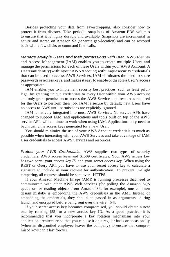
Besides protecting your data from eavesdropping, also consider how to
protect it from disaster. Take periodic snapshots of Amazon EBS volumes
to ensure that it is highly durable and available. Snapshots are incremental in
nature and stored on Amazon S3 (separate geo-location) and can be restored
back with a few clicks or command line calls.
Manage Multiple Users and their permissions with IAM. AWS Identity
and Access Management (IAM) enables you to create multiple Users and
manage the permissions for each of these Users within your AWS Account. A
Userisanidentity(withinyour AWS Account) withuniquesecurity credentials
that can be used to access AWS Services. IAM eliminates the need to share
passwords or access keys, and makes it easy to enable or disable a User’s access
as appropriate.
IAM enables you to implement security best practices, such as least privi-
lege, by granting unique credentials to every User within your AWS account
and only grant permission to access the AWS Services and resources required
for the Users to perform their job. IAM is secure by default; new Users have
no access to AWS until permissions are explicitly granted.
IAM is natively integrated into most AWS Services. No service APIs have
changed to support IAM, and applications and tools built on top of the AWS
service APIs will continue to work when using IAM. Applications only need to
begin using the access keys generated for a new User.
You should minimize the use of your AWS Account credentials as much as
possible when interacting with your AWS Services and take advantage of IAM
User credentials to access AWS Services and resources.
Protect your AWS Credentials. AWS supplies two types of security
credentials: AWS access keys and X.509 certificates. Your AWS access key
has two parts: your access key ID and your secret access key. When using the
REST or Query API, you have to use your secret access key to calculate a
signature to include in your request for authentication. To prevent in-flight
tampering, all requests should be sent over HTTPS.
If your Amazon Machine Image (AMI) is running processes that need to
communicate with other AWS Web services (for polling the Amazon SQS
queue or for reading objects from Amazon S3, for example), one common
design mistake is embedding the AWS credentials in the AMI. Instead of
embedding the credentials, they should be passed in as arguments during
launch and encrypted before being sent over the wire [54].
If your secret access key becomes compromised, you should obtain a new
one by rotating [55] to a new access key ID. As a good practice, it is
recommended that you incorporate a key rotation mechanism into your
application architecture so that you can use it on a regular basis or occasionally
(when an disgruntled employee leaves the company) to ensure that compro-
mised keys can’t last forever.

WWeebb
SSeerrvveerr
AApppp
SSeerrvveerr
DBDB
SSeerrvveerr
Web
Server
Alternately, you can use X.509 certificates for authentication to certain
AWS services. The certificate file contains your public key in a base64-encoded
DER certificate body. A separate file contains the corresponding base64-
encoded PKCS#8 private key. AWS supports multi-factor authentication [56]
as an additional protector for working with your account information on aws.
Amazon.com and AWS Management Console [57].
Secure Your Application. Every Amazon EC2 instance is protected by one
or more security groups [58]—that is, named sets of rules that specify which
ingress (i.e., incoming) network traffic should be delivered to your instance.
You can specify TCP and UDP ports, ICMP types and codes, and source
addresses. Security groups give you basic firewall-like protection for running
instances. For example, instances that belong to a Web application can have
the security group settings shown in Figure 4.4.4.
Amazon EC2
Security Group
Firewall
Only Permit
Web layer
access to
App Layer
Only Permit
App layer
access to
DB Layer
Port 80 (HTTP)
and 443 (HTTPS)
of Web Layer
open to Internet
Only Port 22
(SSH) of App layer
open to only
developers in
corporate office
network
All other
traffic denied
EBS
Volume
FIGURE 4.4.4. Securing your Web application using Amazon EC2 security groups.
App
Server
DB
Server

Another way to restrict incoming traffic is to configure software-based
firewalls on your instances. Windows instances can use the built-in firewall [59].
Linux instances can use netfilter [60] and iptables.
Over time, errors in software are discovered and require patches to fix. You
should ensure the following basic guidelines to maximize security of your
application:
● Regularly download patches from the vendor’s Web site and update your
AMIs.
● Redeploy instances from the new AMIs and test your applications to
ensure that the patches don’t break anything. Ensure that the latest AMI
is deployed across all instances.
● Invest in test scripts so that you can run security checks periodically and
automate the process.
● Ensure that the third-party software is configured to the most secure
settings.
● Never run your processes as root or Administrator login unless absolutely
necessary.
All the standard security practices in the pre-cloud era, such as adopting
good coding practices and isolating sensitive data, are still applicable and
should be implemented.
In retrospect, the cloud abstracts the complexity of the physical security
from you and gives you the control through tools and features so that you can
secure your application.
GREPTHEWEB CASE STUDY
The Alexa Web Search1
Web service allows developers to build customized
search engines against the massive data that Alexa generates (using a Web
crawl) every night. One of the features of their Web service allows users to
query the Alexa search index and get Million Search Results (MSR) back as
output. Developers can run queries that return up to 10 million results.
The resulting set, which represents a small subset of all the documents on the
Web, can then be processed further using a regular expression language. This
allows developers to filter their search results using criteria that are not indexed
by Alexa, thereby giving the developer power to do more sophisticated
searches. Developers can run regular expressions against the actual documents,
even when there are millions of them, to search for patterns and retrieve the
subset of documents that matched that regular expression. This application is
1The service has been deprecated for business reasons; however, the architecture and design
principles are still relevant.
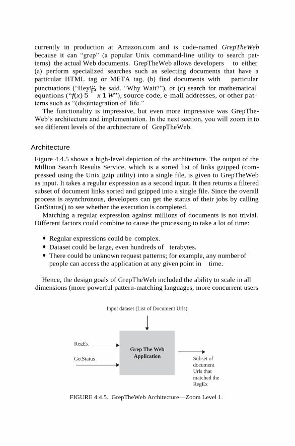
currently in production at Amazon.com and is code-named GrepTheWeb
because it can “grep” (a popular Unix command-line utility to search pat-
terns) the actual Web documents. GrepTheWeb allows developers to either
(a) perform specialized searches such as selecting documents that have a
particular HTML tag or META tag, (b) find documents with particular
punctuations (“Hey!P”, he said. “Why Wait?”), or (c) search for mathematical equations (“f(x) 5 x 1 W”), source code, e-mail addresses, or other pat-
terns such as “(dis)integration of life.”
The functionality is impressive, but even more impressive was GrepThe-
Web’s architecture and implementation. In the next section, you will zoom in to
see different levels of the architecture of GrepTheWeb.
Architecture
Figure 4.4.5 shows a high-level depiction of the architecture. The output of the
Million Search Results Service, which is a sorted list of links gzipped (com-
pressed using the Unix gzip utility) into a single file, is given to GrepTheWeb
as input. It takes a regular expression as a second input. It then returns a filtered
subset of document links sorted and gzipped into a single file. Since the overall
process is asynchronous, developers can get the status of their jobs by calling
GetStatus() to see whether the execution is completed.
Matching a regular expression against millions of documents is not trivial.
Different factors could combine to cause the processing to take a lot of time:
● Regular expressions could be complex.
● Dataset could be large, even hundreds of terabytes.
● There could be unknown request patterns; for example, any number of
people can access the application at any given point in time.
Hence, the design goals of GrepTheWeb included the ability to scale in all
dimensions (more powerful pattern-matching languages, more concurrent users
Input dataset (List of Document Urls)
Subset of
document
Urls that
matched the
RegEx
FIGURE 4.4.5. GrepTheWeb Architecture—Zoom Level 1.
RegEx
GetStatus
Grep The Web
Application
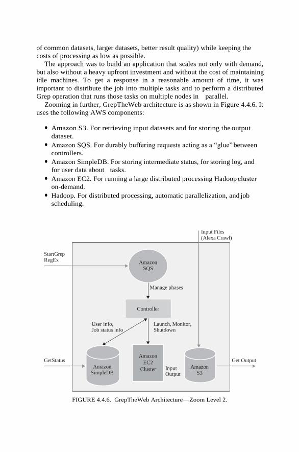
of common datasets, larger datasets, better result quality) while keeping the
costs of processing as low as possible.
The approach was to build an application that scales not only with demand,
but also without a heavy upfront investment and without the cost of maintaining
idle machines. To get a response in a reasonable amount of time, it was
important to distribute the job into multiple tasks and to perform a distributed
Grep operation that runs those tasks on multiple nodes in parallel.
Zooming in further, GrepTheWeb architecture is as shown in Figure 4.4.6. It
uses the following AWS components:
● Amazon S3. For retrieving input datasets and for storing the output
dataset.
● Amazon SQS. For durably buffering requests acting as a “glue” between
controllers.
● Amazon SimpleDB. For storing intermediate status, for storing log, and
for user data about tasks.
● Amazon EC2. For running a large distributed processing Hadoop cluster
on-demand.
● Hadoop. For distributed processing, automatic parallelization, and job
scheduling.
FIGURE 4.4.6. GrepTheWeb Architecture—Zoom Level 2.
Controller
Input Files (Alexa Crawl)
StartGrep RegEx Amazon
SQS
Manage phases
User info, Job status info
Launch, Monitor, Shutdown
GetStatus Get Output
Amazon SimpleDB
Input Output
Amazon S3
Amazon
EC2
Cluster
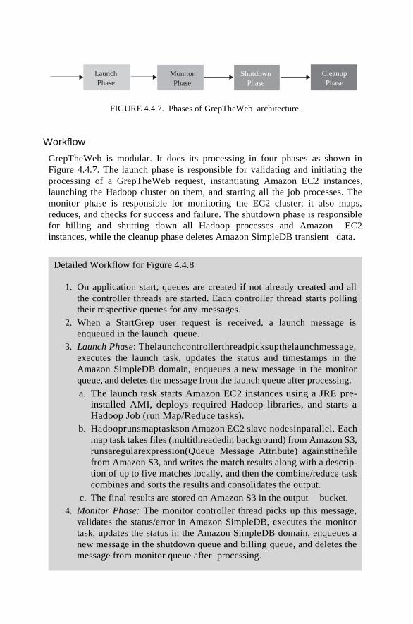
Monitor
Phase
Shutdown
Phase
Launch
Phase
FIGURE 4.4.7. Phases of GrepTheWeb architecture.
Workflow
GrepTheWeb is modular. It does its processing in four phases as shown in
Figure 4.4.7. The launch phase is responsible for validating and initiating the
processing of a GrepTheWeb request, instantiating Amazon EC2 instances,
launching the Hadoop cluster on them, and starting all the job processes. The
monitor phase is responsible for monitoring the EC2 cluster; it also maps,
reduces, and checks for success and failure. The shutdown phase is responsible
for billing and shutting down all Hadoop processes and Amazon EC2
instances, while the cleanup phase deletes Amazon SimpleDB transient data.
Detailed Workflow for Figure 4.4.8
1. On application start, queues are created if not already created and all
the controller threads are started. Each controller thread starts polling
their respective queues for any messages.
2. When a StartGrep user request is received, a launch message is
enqueued in the launch queue.
3. Launch Phase: Thelaunchcontrollerthreadpicksupthelaunchmessage,
executes the launch task, updates the status and timestamps in the
Amazon SimpleDB domain, enqueues a new message in the monitor
queue, and deletes the message from the launch queue after processing.
a. The launch task starts Amazon EC2 instances using a JRE pre-
installed AMI, deploys required Hadoop libraries, and starts a
Hadoop Job (run Map/Reduce tasks).
b. Hadooprunsmaptaskson Amazon EC2 slave nodesinparallel. Each
map task takes files (multithreadedin background) from Amazon S3,
runsaregularexpression(Queue Message Attribute) againstthefile
from Amazon S3, and writes the match results along with a descrip-
tion of up to five matches locally, and then the combine/reduce task
combines and sorts the results and consolidates the output.
c. The final results are stored on Amazon S3 in the output bucket.
4. Monitor Phase: The monitor controller thread picks up this message,
validates the status/error in Amazon SimpleDB, executes the monitor
task, updates the status in the Amazon SimpleDB domain, enqueues a
new message in the shutdown queue and billing queue, and deletes the
message from monitor queue after processing.
Cleanup
Phase

FIGURE 4.4.8. GrepTheWeb Architecture—Zoom Level 3.
a. The monitor task checks for the Hadoop status (JobTracker
success/failure) in regular intervals, and it updates the SimpleDB
items with status/error and Amazon S3 output file.
5. Shutdown Phase: The shutdown controller thread picks up this message
from the shutdown queue, executes the shutdown task, updates the status
and timestamps in Amazon SimpleDB domain, and deletes the message
from the shutdown queue after processing. Likewise, the billing controller
threadpicks up the message from the billing queue and executesthe billing
task of sending usage information to the billing service.
a. The shutdown task kills the Hadoop processes, terminates the EC2
instances after getting EC2 topology information from Amazon
SimpleDB, and disposes of the infrastructure.
b. The billing task gets EC2 topology information, SimpleDB Box
Usage, and Amazon S3 file and query input and calculates the
billing and passes it to the billing service.
6. Cleanup Phase: Archives the SimpleDB data with user info.
7. Users can execute GetStatus on the service endpoint to get the status of
the overall system (all controllers and Hadoop) and download the
filtered results from Amazon S3 after completion.
Launch
Controller
Amazon SQS Billing Queue
Launch Queue
Monitor Queue
Shutdown Queue
Billing
Service
Controller
Shutdown
Controller
Launch Get EC2 Info
Ping
Insert JobID,
Status
Insert Amazon EC2
info
Check for results
Shutdown
Master M Slaves N
Status DB
Put
File
Output
HDFS
Get File
Input
Amazon SimpleDB
Hadoop Cluster on
Amazon EC2 Amazon S3
Monitor
Controller
Billing
Controller

Implementing Best Practices
In the next four subsections, you will see how GrepTheWeb implements the
best practices using different Amazon Web Services.
Elastic Storage Provided by Amazon S3. In GrepTheWeb, Amazon S3
acts as an input as well as an output data store. The input to GrepTheWeb is
the Web itself (compressed form of Alexa’s Web Crawl), stored on Amazon S3
as objects and updated frequently. Because the Web Crawl dataset can be huge
(usually in terabytes) and always growing, there was a need for a distributed,
elastic, persistent storage. Amazon S3 proved to be a perfect fit.
Loose Coupling Using Amazon SQS. Amazon SQS was used as message-
passing mechanism between components. It acts as “glue” that wired different
functional components together. This not only helped in making the different
components loosely coupled, but also helped in building an overall more failure
resilient system.
Buffer. If one component is receiving and processing requests faster than other
components (an unbalanced producer consumer situation), buffering will help
make the overall system more resilient to bursts of traffic (or load). Amazon
SQS acts as a transient buffer between two components (controllers) of the
GrepTheWeb system. If a message is sent directly to a component, the receiver
will need to consume it at a rate dictated by the sender. For example, if the
billing system was slow or if the launch time of the Hadoop cluster was more
than expected, the overall system would slow down, because it would just have
to wait. With message queues, sender and receiver are decoupled and the queue
service smooths out any “spiky” message traffic.
Isolation. Interaction between any two controllers in GrepTheWeb is through
messages in the queue, and no controller directly calls any other controller. All
communication and interaction happens by storing messages in the queue (en-
queue) and retrieving messages from the queue (de-queue). This makes the
entire system loosely coupled and makes the interfaces simple and clean.
Amazon SQS provided a uniform way of transferring information between
the different application components. Each controller’s function is to retrieve the
message, process the message (execute the function), and store the message in
another queue while they are completely isolated from others.
Asynchrony. Because it was difficult to know how much time each phase
would take to execute (e.g., the launch phase decides dynamically how many
instances need to start based on the request and hence execution time is
unknown), Amazon SQS helped by making the system behave in an

asynchronous fashion. Now, if the launch phase takes more time to process or
the monitor phase fails, the other components of the system are not affected
and the overall system is more stable and highly available.
Storing Statuses in Amazon SimpleDB. One use for a database in cloud
applications is to track statuses. Since the components of the system run
asynchronously, there is a need to obtain the status of the system at any given
point in time. Moreover, since all components are autonomous and discrete,
there is a need for a query-able data store that captures the state of the system.
Because Amazon SimpleDB is schema-less, there is no need to define the
structure of a record beforehand. Every controller can define its own structure
and append data to a “job” item. For example: For a given job, “run email
address regex over 10 million documents,” the launch controller will add/
update the “launch_status” attribute along with the “launch_starttime,” while
the monitor controller will add/update the “monitor_status” and “hadoop_
status” attributes with enumeration values (running, completed, error, none). A
GetStatus() call will query Amazon SimpleDB and return the state of each
controller and also the overall status of the system.
Component services can query Amazon SimpleDB anytime because
controllers independently store their states—one more nice way to create
asynchronous highly available services. Although a simplistic approach was
used in implementing the use of Amazon SimpleDB in GrepTheWeb, a more
sophisticated approach, where there was complete, almost real-time monitor-
ing, would also be possible—For example, storing the Hadoop JobTracker
status to show how many maps have been performed at a given moment.
Amazon SimpleDB is also used to store active Request IDs for historical and
auditing/billing purposes.
In summary, Amazon SimpleDB is used as a status database to store the
different states of the components and a historical/log database for querying
high-performance data.
Intelligent Elasticity Implemented Using Amazon EC2. In GrepTheWeb,
the controller code runs on Amazon EC2 instances. The launch controller
spawns master and slave instances using a preconfigured Amazon machine
image (AMI). Since the dynamic provisioning and decommissioning happens
using simple Web service calls, GrepTheWeb knows how many master and
slave instances need to be launched.
The launch controller makes an educated guess, based on reservation logic,
of how many slaves are needed to perform a particular job. The reservation
logic is based on the complexity of the query (number of predicates, etc.) and
the size of the input dataset (number of documents to be searched). This was
also kept configurable so that overall processing time can be reduced by simply
specifying the number of instances to launch. After launching the instances and
starting the Hadoop cluster on those instances, Hadoop will appoint a master

Example
Regular Expression
“A(.*)zon”
Format of the line in the Input dataset
[URL] [Title] [charset] [size] [S3 Object Key of .gz file] [offset] http://www.amazon.com/gp/browse.html?node=3435361 Amazon Web us-ascii 3509
/2008/01/08/51/1/51_1_20080108072442_crawl100.arc.gz 70150864
Mapper Implementation
Key = line number and value = line in the input dataset
Create a signed URL (using Amazon AWS credentials) using the contents of key-value Read (fetch) Amazon S3 Object (file) into a buffer Run regular expression on that buffer If there is match, collect the output in new set of key-value pairs (key = line, value = up to 5 matches)
Reducer Implementation Pass-through (Built-in Identity Function) and write the results back to S3.
FIGURE 4.4.9. Map reduce operation (in GrepTheWeb).
and slaves, handles the negotiating, handshaking, and security token distribu-
tion (SSH keys, certificates), and runs the grep job.
GrepTheWeb Hadoop implementation
Hadoop is an open source distributed processing framework that allows
computation of large datasets by splitting the dataset into manageable chunks,
spreading it across a fleet of machines and managing the overall process by
launching jobs, processing the job no matter where the data are physically
located and, at the end, aggregating the job output into a final result.
Hadoop is a good fit for the GrepTheWeb application. Because each grep
task can be run in parallel independently of other grep tasks, using the parallel
approach embodied in Hadoop is a perfect fit.
For GrepTheWeb, the actual documents (the web) are crawled ahead of time
and stored on Amazon S3. Each user starts a grep job by calling the StartGrep
function at the service endpoint. When triggered, masters and slave nodes
(Hadoop cluster) are started on Amazon EC2 instances. Hadoop splits the input
(document with pointers to Amazon S3 objects) into multiple manageable
chunks of 100 lines each and assign the chunk to a slave node to run the map
task [61]. The map task reads these lines and is responsible for fetching the files
from Amazon S3, running the regular expression on them and writing the results
locally. If there is no match, there is no output. The map tasks then passes the
results to the reduce phase, which is an identity function (pass through) to
aggregate all the outputs. The “final” output is written back to Amazon S3.
FUTURE RESEARCH DIRECTIONS
The day is not too far when applications will cease to be aware of physical
hardware. Much like plugging in a microwave in order to power it doesn’t
require any knowledge of electricity, one should be able to plug in an

application to the cloud in order to receive the power it needs to run, just like a
utility. As an architect, you will manage abstract compute, storage, and
network resources instead of physical servers. Applications will continue to
function even if the underlying physical hardware fails or is removed or
replaced. Applications will adapt themselves to fluctuating demand patterns
by deploying resources instantaneously and automatically, thereby achieving
highest utilization levels at all times. Scalability, security, high availability,
fault-tolerance, testability, and elasticity will be configurable properties of
the application architecture and will be an automated and intrinsic part of the
platform on which they are built.
However, we are not there yet. Today, you can build applications in the
cloud with some of these qualities by implementing the best practices high-
lighted in the chapter. Best practices in cloud computing architectures will
continue to evolve, and as researchers we should focus not only on enhancing
the cloud but also on building tools, technologies, and processes that will make
it easier for developers and architects to plug in applications to the cloud easily.
BUILDING CONTENT DELIVERY NETWORKS
USING CLOUDS
INTRODUCTION
Numerous “storage cloud” providers (or “Storage as a Service”) have recently
emerged that can provide Internet-enabled content storage and delivery
capabilities in several continents, offering service-level agreement (SLA)-
backed performance and uptime promises for their services. Customers are
charged only for their utilization of storage and transfer of content (i.e., a utility
computing model), which is typically on the order of cents per gigabyte. This
represents a large paradigm shift away from typical hosting arrangements that
were prevalent in the past, where average customers were locked into hosting
contracts (with set monthly/yearly fees and excess data charges) on shared
hosting services like DreamHost . Larger enterprise customers typically
utilized pervasive and high-performing Content Delivery Networks (CDNs)
like Akamai [3, 4] and Limelight, who operate extensive networks of “edge”
servers that deliver content across the globe. In recent years it has become
increasingly difficult for competitors to build and maintain competing CDN
infrastructure, and a once healthy landscape of CDN companies has been
reduced to a handful via mergers, acquisitions, and failed companies .
However, far from democratizing the delivery of content, the most pervasive
remaining CDN provider (Akamai) is priced out of the reach of most small to
medium-sized enterprises (SMEs), government agencies, universities, and
charities . As a result, the idea of utilizing storage clouds as a poor man’s CDN
is very enticing. At face value, these storage providers promise the ability to
rapidly and cheaply “scale-out” to meet both flash crowds (which is the dream
and the nightmare of most Web-site operators) and anticipated increases in

demand. Economies of scale, in terms of
cost effectiveness and performance for both providers and end users, could be
achieved by leveraging existing “storage cloud” infrastructure, instead of
investing large amounts of money in their own content delivery platform or
utilizing one of the incumbent operators like Akamai. In Section 4.5.2, we
analyze the services provided by these storage providers, and well as their
respective cost structures, to ascertain if they are a good fit for basic content
delivery needs.
These emerging services have reduced the cost of content storage and delivery
by several orders of magnitude, but they can be difficult to use for nondevelopers,
because each service is best utilized via unique Web services or programmer APIs
and have their own unique quirks. Many Web sites have utilized individual
storage clouds to deliver some or all of their content , most notably the New
York Times and SmugMug [9]; however, there is no general-purpose, reusable
framework to interact with multiple storage cloud providers and leverage their
services as a content delivery network. Most “storage cloud” providers are
merely basic file storage and delivery services and do not offer the capabilities of a
fully featured CDN such as automatic replication, fail-over, geographical load
redirection, and load balancing. Furthermore, a customer may need coverage in
more locations than offered by a single provider. To address this, in Section
4.5.3 we introduce MetaCDN, a system that utilizes numerous storage
providers in order to create an overlay network that can be used as a high-
performance, reliable, and redundant geographically distributed CDN.
However, in order to utilize storage and file delivery from these providers in
MetaCDN as a Content Delivery Network, we want to ensure that they provide
sufficient performance (i.e., predictable and sufficient response time and
throughput) and reliability (i.e., redundancy, file consistency). While individual
storage clouds have been trialed successfully for application domains such as
science grids [10, 11] and offsite file backup [23], their utility for
generalpurpose content delivery, which requires low latency and high
throughput, has not been evaluated rigorously. In Section 4.5.4 we summarize
the performance findings to date for popular storage clouds as well as for the
MetaCDN overlay itself. In Section 4.5.5 we consider the future directions of
MetaCDN and identify potential enhancements for the service. Finally, in
Section 4.5.6 we offer some concluding remarks and summarize our
contribution.
BACKGROUND/RELATED WORK
In order to ascertain the feasibility of building a content delivery network service
from storage clouds, it is important to ascertain whether the storage clouds used
possess the necessary features, performance, and reliability characteristics to act
as CDN replica servers. While performance is crucial for content delivery, we also
need to examine the cost structures of the different providers. At face value these
services may appear ludicrously cheap; however, they have subtle differences in
pricing and the type of services billed to the end user, and as a result a user could

get a nasty surprise if they have not understood what they will be charged for.

For the purposes of this chapter, we chose to analyze the four most prominent
storage cloud providers: Amazon Simple Storage Service (S3) and CloudFront
(CF), Nirvanix Storage Delivery Network (SDN), Rackspace Cloud Files, and
Microsoft Azure Storage, described in Sections 4.5.2.1, 4.5.2.2, 4.5.2.3 and
4.5.2.4, respectively. At the time of writing, Amazon offers storage nodes in
the United States and Europe (specifically, Ireland) while Nirvanix has storage
nodes in the United States (over three separate sites in California, Texas, and
New Jersey), Germany, and Japan. Another storage cloud provider of note is
Rackspace Cloud Files, located in Dallas, Texas, which recently launched in
late 2008. Microsoft has also announced their cloud storage offering, Azure
Storage Service, which has data centers in Asia, Europe, and the United States
and formally launched as an SLA-backed commercial service in April 2010.
An enterprise class CDN service typically offers audio and video encoding and
adaptive delivery, so we will consider cloud-based encoding services such as
encoding.com that offer similar capability in Section 4.5.2.5.
Amazon Simple Storage and CloudFront
Amazon S3 was launched in the United States in March 2006 and in Europe in
November 2007, opening up the huge infrastructure that Amazon themselves
utilize to run their highly successful e-commerce company, Amazon.com. In
November 2008, Amazon launched CloudFront, a content delivery service that
added 14 edge locations (8 in the United States, 4 in Europe, and 2 in Asia).
However, unlike S3, CloudFront does not offer persistent storage. Rather, it is
analogous to a proxy cache, with files deployed to the different CloudFront
locations based on demand and removed automatically when no longer
required. CloudFront also offers “streaming distributions” that can distribute
audio and video content in real time, using the Real-Time Messaging Protocol
(RTMP) instead of the HTTP protocol.
Amazon provides REST and SOAP interfaces to its storage resources,
allowing users the ability to read, write, or delete an unlimited amount
of objects, with sizes ranging from 1 byte to 5 gigabytes each. As noted in
Table 4.5.1, Amazon S3 has a storage cost of $0.15 per GB/month in their
standard U.S. and EU data centers, or $0.165 per GB/month in their North
California data center. Incoming traffic (i.e., uploads) are charged at $0.10 per
GB/month, and outgoing traffic (i.e., downloads) are charged at $0.15 per GB/
month, from the U.S. or EU sites. For larger customers, Amazon S3 has a
sliding scale pricing scheme, which is depicted in Figure 4.5.1. Discounts for
outgoing data occur after 10TB, 50 TB and 150 TB of data a month has been
transferred, resulting in a subtly sublinear pricing response that is depicted
in the figure. As a point of comparison, we have included the “average” cost of
the top four to five major incumbent CDN providers. An important facet of

TABLE 4.5.1. Pricing Comparison of Cloud Storage
Vendors
Amazon
Microsoft Microsoft
Cost
Type
Nirvanix
SDNa
S3
U.S./EU
Standardb
Amazon
S3 U.S.
N. Californiab
Rackspace
Cloud
Files
Azure
Storage
NA/EU
Azure
Storage
Asia Pacific
Incoming
data
($/GB)
Outgoing
data
($/GB)
Storage
($/GB)
Requests
($/1000
PUT)
Requests
($/10,000
GET)
0.18 0.10 0.10 0.08 0.10 0.30
0.18 0.15 0.15 0.22 0.15 0.45
0.25 0.15 0.165 0.15 0.15 0.15
0.00 0.01 0.011 0.02 0.001 0.001
0.00 0.01 0.011 0.00 0.01 0.01
a Pricing valid for storage, uploads, and download usage under 2 TB/month. b Pricing valid for first 50 TB/month of storage used and first 1 GB/month data transfer out.
120000
100000
80000
60000
40000
20000
0
0 50000 100000 150000 200000 250000
Outgoing TB Data/month
FIGURE 4.5.1. Pricing comparison of cloud storage vendors based on usage.
Amazon S3 (all)
Amazon CF US/EU
Amazon CF HK/SING
Amazon CF JAP
Nirvarix SDN
Rackspace Cloud Files
Windows Azure Storage NA/EU
Windows Azure Storage APAC
Traditional CDN (avg.)
$U
SD
/month

Amazon’s pricing that should be noted by users (but is not captured by Figure
4.5.1) is the additional cost per 1000 PUT/POST/LIST or 10,000 GET HTTP
requests, which can add up depending on the type of content a user places on
Amazon S3. While these costs are negligible if a user is utilizing Amazon S3 to
primarily distribute very large files, if they are storing and serving smaller files,
a user could see significant extra costs on their bill. For users serving content
with a lower average file size (e.g., 100 kB), a larger cost is incurred.
Nirvanix Storage Delivery Network
Nirvanix launched its Amazon S3 competitor, the Nirvanix Storage Delivery
Network (SDN), on September 2007. The Nirvanix service was notable in that
it had an SLA-backed uptime guarantee at a time when Amazon S3 was simply
operated on a best-effort service basis. Unsurprisingly, shortly after Nirvanix
launched its SDN, Amazon added their own SLA-backed uptime guarantees.
Nirvanix differentiates itself in several ways (depicted in Table 4.5.2), notably
by having coverage in four regions, offering automatic file replication over
sites in the SDN for performance and redundancy, and supporting file sizes up
to 256 GB. Nirvanix is priced slightly higher than Amazon’s service, and they
do not publish their pricing rates for larger customers (2 TB/month). Nirvanix
provides access to their resources via SOAP or REST interfaces, as well as
providing SDK’s in Java, PHP Zend, Python, and C#.
Rackspace Cloud Files
Rackspace (formerly Mosso) Cloud Files provides a self-serve storage and
deliveryserviceinafashionsimilartothatoftheAmazonandNirvanixofferings.
Thecore Cloud Filesofferingisservedfromamultizoned, redundantdatacenter
in Dallas, Texas. The service is notable in that it also provides CDN integration.
Rather than building their own CDN extension to the Cloud Files platform as
TABLE 4.5.2. Feature Comparison of Cloud Storage Vendors
Feature
Nirvanix
SDN
Amazon
S3
Amazon
Cloud Front
Rackspace
Cloud
Files
Microsoft
Azure
Storage
SLA 99.9 99.9 99.9 99.9 99.9
Max. size 256 GB 5 GB 5 Gb 5 GB 50 GB
U.S. PoP Yes Yes Yes Yes Yes
EU PoP Yes Yes Yes Yes Yes
Asia PoP Yes No Yes Yes Yes
Aus PoP No No No Yes No
File ACL Yes Yes Yes Yes Yes
Replication Yes No Yes Yes No
API Yes Yes Yes Yes Yes

Amazon has done for S3, Rackspace has partnered with a traditional CDN
service, Limelight, to distribute files stored on the Cloud Files platform to edge
nodes operated by Limelight. Unlike Amazon CloudFront, Rackspace does not
charge for moving data from the core Cloud Files servers to the CDN edge
locations.RackspaceprovidesRESTfulAPIsaswellasAPIbindingsforpopular
languages such as PHP, Python, Ruby, Java, and .NET.
Azure Storage Service
Microsoft’s Windows Azure platform offers a comparable storage and delivery
platform called Azure Storage, which provides persistent and redundant
storage in the cloud. For delivering files, the Blob service is used to store files
up to 50 GB in size. On a per storage account basis, the files can be stored and
delivered from data centers in Asia (East and South East), the United States
(North Central and South Central), and Europe (North and West). Azure
Storage accounts can also be extended by a CDN service that provides an
additional 18 locations globally across the United States, Europe, Asia,
Australia, and South America. This CDN extension is still under testing and
is currently being offered to customers as a Community Technology Preview
(CTP) at no charge.
Encoding Services
Video and audio encoding services are also individually available from cloud
vendors. Two notable providers are encoding.com and Nirvanix (previously
discussed in Section 4.5.2.2). The endoing.com service is a cloud-based video
encoding platform that can take a raw video file and generate an encoded file
suitable for streaming. The service supports a number of video output formats
that are suitable for smartphones (e.g., iPhone) right up to high-quality H.264
desktop streaming. A variety of integration services are available, allowing the
encoded file to be placed on a private server, Amazon S3 bucket, or Rackspace
Cloud Files folder. Nirvanix also offers video encoding as a service, offering a
limited number of H.263 and H.264 encoding profiles in a Flash (flv) or MPEG-4
(mp4) container. The resulting encodes are stored on the Nirvanix SDN.
4.5.3 METACDN: HARNESSING STORAGE CLOUDS FOR
LOW-COST, HIGH-PERFORMANCE CONTENT DELIVERY
In this section we introduce MetaCDN, a system that leverages the existing
storage clouds and encoding services described in Section 4.5.2, creating an
integrated overlay network that aims to provide a low-cost, high-performance,
easy-to-use content delivery network for content creators and consumers.
The MetaCDN service (depicted in Figure 4.5.2) is presented to end users in
two ways. First, it can be presented as a Web portal, which was developed using

Amazon S3 &
CloudFront
JetS3t toolkit
Java SDK
Open Source
Niranix SDN
Nirvanix SDK
Java SDK
Nirvanix, Inc
Mosso Cloud
Files CDN
Cloud Files SDK
Java SDK
Mosso, Inc
Microsoft Azure
Storage Service
AzureConnector
Java stub
MetaCDN.org
Shared/Private
Host
WebDAVConnector
Java stub
MetaCDN.org
SCPConnector
Java stub
AmazonS3Connector NirvanixConnector CloudFilesConnector MetaCDN.org
Java stub
MetaCDN.org
Java stub
MetaCDN.org
Java stub
MetaCDN.org
FTPConnector Java stub
MetaCDN.org
MetaCDN
Manager
MetaCDN
MetaCDN QoS
Monitor
MetaCDN
Allocator
MetaCDN
Database
EncodingEncoder
Java stub
MetaCDN.org
NirvanixEncoder
Java stub
MetaCDN.org
Encoding.com
Nirvanix
Web Portal Web Service Load Redirector Java (JSF/EJB) based portal Support HTTP POST
New/view/modify deployment
SOAP Web Service RESTful Web Service
Programmatic access
Random redirection Geographical redirection
Least cost redirection
FFmpegEncoder
Java stub
MetaCDN.org
Shared/Private
Host
<uses> <uses> <uses> <uses> <uses> <uses>
User 1 User 2 User n Consumer 1 Consumer 2 Consumer n
FIGURE 4.5.2. The MetaCDN architecture.
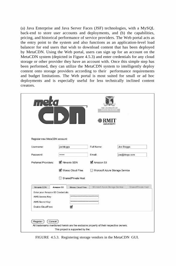
(a) Java Enterprise and Java Server Faces (JSF) technologies, with a MySQL
back-end to store user accounts and deployments, and (b) the capabilities,
pricing, and historical performance of service providers. The Web portal acts as
the entry point to the system and also functions as an application-level load
balancer for end users that wish to download content that has been deployed
by MetaCDN. Using the Web portal, users can sign up for an account on the
MetaCDN system (depicted in Figure 4.5.3) and enter credentials for any cloud
storage or other provider they have an account with. Once this simple step has
been performed, they can utilize the MetaCDN system to intelligently deploy
content onto storage providers according to their performance requirements
and budget limitations. The Web portal is most suited for small or ad hoc
deployments and is especially useful for less technically inclined content
creators.
FIGURE 4.5.3. Registering storage vendors in the MetaCDN GUI.

The second method of accessing the MetaCDN service is via RESTful Web
Services. These Web Services expose all of the functionality of the MetaCDN
system. This access method is most suited for customers with more complex
and frequently changing content delivery needs, allowing them to integrate
the MetaCDN service in their own origin Web sites and content creation
workflows.
Integrating “Cloud Storage” Providers
The MetaCDN system works by integrating with each storage provider via
connectors (shown in Figures 4.5.2 and 4.5.4) that provides an abstraction to
hide the complexity arising from the differences in how each provider allows
access to their systems. An abstract class, DefaultConnector, prescribes the
basic functionality that each provider could be expected to support, and it must
be implemented for all existing and future connectors. These include basic
operations like creation, deletion, and renaming of replicated files and folders.
If an operation is not supported on a particular service, then the connector for
that service throws a FeatureNotSupportedException. This is crucial, because
while the providers themselves have very similar functionality, there are some
key differences, such as the largest allowable file size or the coverage footprint.
Figure 4.5.4 shows two connectors (for Amazon S3 and Nirvanix SDN,
respectively), highlighting one of Amazon’s most well-known limitations—
that you cannot rename a file, which should result in a
FeatureNotSupportedException if called. Instead, you must delete the file and
re-upload it. The Nirvanix connector throws a FeatureNotSupportedException
when you try and create a Bittorrent deployment, because it does not support
this functionality, unlike Amazon S3. Connectors are also available for (a)
shared or private hosts via connectors for commonly available FTP-accessible
shared Web hosting (shown in Figure 4.5.4) and (b) privately operated Web
hosting that may be available via SSH/SCP or WebDAV protocols.
AmazonS3Connector createFolder(foldername, location) deleteFolder(foldername) createFile(file, foldername,
location, date) createFile(fileURL, foldername,
location, date) renameFile(filename, newname,
location) throws FeatureNetSupportedException
createTorrent(file) createTOrrent(fileURL) deleteFile(file, location) listFilesAndFolders() deleteFilesAndFolders()
<<exception>>
FeatureNotSupportedException
FeatureNotSupportedException(msg)
DefaultConnector
DEPLOY_USA DEPLOY_EU DEPLOY_ASIA DEPLOY_AUS createFolder(foldername, location) deleteFolder(foldername) createFile(file, foldername,
location, date) createFile(fileURL, foldername,
locatrion, date) renameFile(filename, newname,
location) createTorrent(file) createTorrent(fileURL) deleteFile(file, location) listFilesAndFolders() deleteFilesAndFolders()
NirvanixConnector createFolder(foldername, location) deleteFolder(foldername) createFile(file, foldername,
location, date) createFile(fileURL, foldername,
locatrion, date) renameFile(filename, newname,
location) createTorrent(file) throws
FeatureNotSupportedException createTorrent(fileURL) throws
FeatureNotSupportedException deleteFile(file, location) listFilesAndFolders() deleteFilesAndFolders()
FIGURE 4.5.4. Design of the MetaCDN connectors.
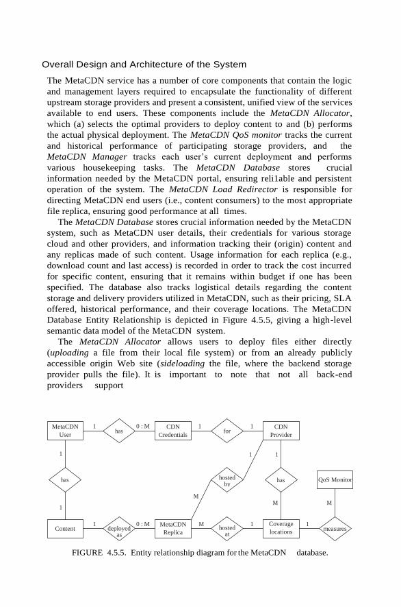
Overall Design and Architecture of the System
The MetaCDN service has a number of core components that contain the logic
and management layers required to encapsulate the functionality of different
upstream storage providers and present a consistent, unified view of the services
available to end users. These components include the MetaCDN Allocator,
which (a) selects the optimal providers to deploy content to and (b) performs
the actual physical deployment. The MetaCDN QoS monitor tracks the current
and historical performance of participating storage providers, and the
MetaCDN Manager tracks each user’s current deployment and performs
various housekeeping tasks. The MetaCDN Database stores crucial
information needed by the MetaCDN portal, ensuring reli1able and persistent
operation of the system. The MetaCDN Load Redirector is responsible for
directing MetaCDN end users (i.e., content consumers) to the most appropriate
file replica, ensuring good performance at all times.
The MetaCDN Database stores crucial information needed by the MetaCDN
system, such as MetaCDN user details, their credentials for various storage
cloud and other providers, and information tracking their (origin) content and
any replicas made of such content. Usage information for each replica (e.g.,
download count and last access) is recorded in order to track the cost incurred
for specific content, ensuring that it remains within budget if one has been
specified. The database also tracks logistical details regarding the content
storage and delivery providers utilized in MetaCDN, such as their pricing, SLA
offered, historical performance, and their coverage locations. The MetaCDN
Database Entity Relationship is depicted in Figure 4.5.5, giving a high-level
semantic data model of the MetaCDN system.
The MetaCDN Allocator allows users to deploy files either directly
(uploading a file from their local file system) or from an already publicly
accessible origin Web site (sideloading the file, where the backend storage
provider pulls the file). It is important to note that not all back-end
providers support
FIGURE 4.5.5. Entity relationship diagram for the MetaCDN database.
MetaCDN
User
CDN
Credentials
CDN
Provider
Content MetaCDN
Replica
Coverage
locations
QoS Monitor
1 has
0 : M 1 for
1
1 1 1
has hosted by
has
M
1 M M
1 deployed
as
0 : M M hosted
at
1 1 measures
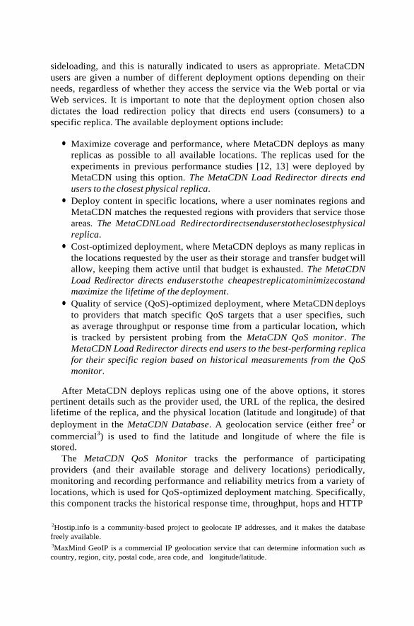
sideloading, and this is naturally indicated to users as appropriate. MetaCDN
users are given a number of different deployment options depending on their
needs, regardless of whether they access the service via the Web portal or via
Web services. It is important to note that the deployment option chosen also
dictates the load redirection policy that directs end users (consumers) to a
specific replica. The available deployment options include:
● Maximize coverage and performance, where MetaCDN deploys as many
replicas as possible to all available locations. The replicas used for the
experiments in previous performance studies [12, 13] were deployed by
MetaCDN using this option. The MetaCDN Load Redirector directs end
users to the closest physical replica.
● Deploy content in specific locations, where a user nominates regions and
MetaCDN matches the requested regions with providers that service those
areas. The MetaCDNLoad Redirectordirectsenduserstotheclosestphysical
replica.
● Cost-optimized deployment, where MetaCDN deploys as many replicas in
the locations requested by the user as their storage and transfer budget will
allow, keeping them active until that budget is exhausted. The MetaCDN
Load Redirector directs enduserstothe cheapestreplicatominimizecostand
maximize the lifetime of the deployment.
● Quality of service (QoS)-optimized deployment, where MetaCDN deploys
to providers that match specific QoS targets that a user specifies, such
as average throughput or response time from a particular location, which
is tracked by persistent probing from the MetaCDN QoS monitor. The
MetaCDN Load Redirector directs end users to the best-performing replica
for their specific region based on historical measurements from the QoS
monitor.
After MetaCDN deploys replicas using one of the above options, it stores
pertinent details such as the provider used, the URL of the replica, the desired
lifetime of the replica, and the physical location (latitude and longitude) of that
deployment in the MetaCDN Database. A geolocation service (either free2
or
commercial3) is used to find the latitude and longitude of where the file is
stored.
The MetaCDN QoS Monitor tracks the performance of participating
providers (and their available storage and delivery locations) periodically,
monitoring and recording performance and reliability metrics from a variety of
locations, which is used for QoS-optimized deployment matching. Specifically,
this component tracks the historical response time, throughput, hops and HTTP
2Hostip.info is a community-based project to geolocate IP addresses, and it makes the database
freely available. 3MaxMind GeoIP is a commercial IP geolocation service that can determine information such as
country, region, city, postal code, area code, and longitude/latitude.

response codes (e.g., 2XX, 3XX, 4XX, or 5XX, which denotes success,
redirection/proxying, client error, or server error) of replicas located at each
coverage location. This information is utilized when performing a QoS-
optimized deployment (described previously).
This component also ensures that upstream providers are meeting their
service-level agreements (SLAs), and it provides a logging audit trail to allow
end users to claim credit in the event that the SLA is broken. This is crucial,
because you cannot depend on the back-end service providers themselves to
voluntarily provide credit or admit fault in the event of an outage. In effect, this
keeps the providers “honest”; and due to the agile and fluid nature of the
system, MetaCDN can redeploy content with minimal effort to alternative
providers that can satisfy the QoS constraints, if available.
The MetaCDN Manager has a number of housekeeping responsibilities.
First, it ensures that all current deployments are meeting QoS targets of users
that have made QoS optimized deployments. Second, it ensures that replicas
are removed when no longer required (i.e., the “deploy until” date set by the
user has expired), ensuring that storage costs are minimized at all times. Third,
for users that have made cost-optimized deployments, it ensures that a user’s
budget has not been exceeded, by tracking usage (i.e., storage and downloads)
from auditing information provided by upstream providers.
Integration of Geo-IP Services and Google Maps
Cloud storage offerings are already available from providers located across the
globe. The principle of cloud computing and storage is that you shouldn’t need
to care where the processing occurs or where your data are stored—the services
are essentially a black box. However, your software and data are subject to the
laws of the nations they are executed and stored in. Cloud storage users could
find themselves inadvertently running afoul of the Digital Millennium
Copyright Act (DMCA)4
or Cryptography Export laws that may not apply to
them in their own home nations. As such, it is important for cloud storage
users to know precisely where their data are stored. Furthermore, this
information is crucial for MetaCDN load balancing purposes, so end users are
redirected to the closest replica, to maximize their download speeds and
minimize latency. To address this issue, MetaCDN offers its users the ability to
pinpoint exactly where their data are stored via geolocation services and
Google Maps integration. When MetaCDN deploys replicas to different cloud
storage providers, they each return a URL pointing to the location of the
replica. MetaCDN then utilizes a geolocation service to find the latitude and
longitude of where the file is stored. This information is stored in the
MetaCDN database
and can be overlaid onto a Google Maps view (see Figure 4.5.6) inside the
MetaCDN portal, giving users a bird’s-eye view of where their data are
currently being stored (depicted in Figure 4.5.6).
4Available at http://www.copyright.gov/legislation/dmca.pdf.

FIGURE 4.5.6. Storage providers overlaid onto a Google Map view.
Load Balancing via DNS and HTTP
The MetaCDN Load Redirector is responsible for directing MetaCDN end users
(i.e., content consumers) to the most appropriate file replica. When a MetaCDN
user deploys content, they are given a single URL, in the format http://www.
metacdn.org/MetaCDN/FileMapper?itemid 5 {item_id}, where item_id is a
unique key associated with the deployed content. This provides a single
namespace, which is more convenient for both MetaCDN users (content
deployers) and end users (content consumers), and offers automatic and totally
transparent load balancing for the latter.
Different load balancing and redirection policies can be utilized, including
simple random allocation, where end users are redirected to a random replica;
geographically aware redirection, where end users are redirected to their
physically closest replica; least-cost redirection, where end users are directed
to the cheapest replica from the content deployer’s perspective; and QoS-aware
redirection, where end users are directed to replicas that meet certain
performance criteria, such as response time and throughput.

MetaCDN end user
Resolve www.metacdn.org
Return IP of closest MetaCDN gateway,
www-na.metacdn.org
DNS Server MetaCDN gateway
GET http://metacdn.org/MetaCDN/FileMapper?itemid=1
HTTP 302 Redirect to
http://metacdn-us-username.s3.amazonaws.com/filename.pdf
Resolve metacdn-us-username.s3.amazonaws.com
Return IP of metacdn-us-username-s3.amazonaws.com
processRequest ()
geoRedirect ()
Amazon S3 USA
GET http://metacdn-us-username.s3.amazonaws.com/filename.pdf
Return replica
FIGURE 4.5.7. MetaCDN Load Redirector.
The load balancing and redirection mechanism is depicted in Figure 4.5.7,
for an example scenario where an end user on the East Coast of the United
States wishes to download a file. The user requests a MetaCDN URL such as
http://www.metacdn.org/MetaCDN/FileMapper?itemid 5 1, and the browser
attempts to resolve the base hostname, www.metacdn.org. The authoritative
DNS (A-DNS) server for this domain resolves this request to the IP address
of the closest copy of the MetaCDN portal—in this case www-na.metacdn.org.
The user (or more typically their Web browser) then makes a HTTP GET
request for the desired content on the MetaCDN gateway. In the case of
geographically aware redirection, the MetaCDN load redirector is triggered to
select the closest replica for the end user, in an effort to maximize performance
and minimize latency. MetaCDN utilizes a geolocation service (mentioned
previously) to find the geographical location (latitude and longitude) of the end
user, and it measures their distance from each matching replica using a simple
spherical law of cosines, or a more accurate approach such as the Vincenty
formula for distance between two latitude/longitude points , in order to find the
closest replica. While there is a strong correlation between the performance
experienced by the end user and their locality to replicas (which was found in
previous work [12, 13] and summarized in Section 4.5.4), there is no guarantee
that the closest replica is always the best choice, due to cyclical and transient
fluctuations in load on the network path. As such, we intend to investigate the
effectiveness of more sophisticated active measurement approaches such as
CDN-based relative network positioning (CRP) , IDMaps , or OASIS to
ensure that end users are always directed to the best-performing replica.

PERFORMANCE OF THE METACDN OVERLAY
In order to evaluate the potential of using storage cloud providers for content
delivery, in prior work [12, 13] we evaluated the major provider nodes currently
available to us, in order to test the throughput and response time of these data
sources. We also looked at the effectiveness of the MetaCDN overlay in
choosing the most appropriate replica. The files in these experiments were
deployed by the MetaCDN Allocator, which was instructed to maximize
coverage and performance, and consequently the test files were deployed on
all available nodes. As noted in the previous section, the default MetaCDN
load redirection policy for this deployment option is to redirect end users to the
physically closest replica. At the time of the first experiment, we could utilize
one node in the United States (Seattle, WA) and one node in Ireland (Dublin).
Nirvanix provides two nodes in the United States (both in California), one
node in Singapore, and one node in Germany. The test files were also cached
where possible using Coral CDN [22]. Coral replicates the file to participating
Coral proxy nodes on an as-needed basis, depending on where the file is
accessed. The second experiment included storage nodes offered by Amazon
CloudFront and Rackspace Cloud Files (described in Section 4.5.2).
For the first experiment, we deployed clients in Australia (Melbourne), France
(Sophia Antipolis), Austria (Vienna), the United States (New York and San
Diego), and South Korea (Seoul). Each location had a high-speed connection to
major Internet backbones to minimize the chance of the client being the
bottleneck during this experiment. The experiment was run simultaneously at
each client location over a 24-hour period, during the middle of the week. As the
test spans 24 hours, it experiences localized peak times in each of the geographical
regions. Each hour, the client sequentially downloads each test file from each
available node a total of 30 times, for statistical significance. The file is
downloaded using the Unix utility, wget, with the no-cache and no-dns-cache
options to ensure that for each download a fresh file is always downloaded (and
not sourced from any intermediary cache) and that the DNS lookup is not
cached either.
In the interests of brevity, we present a summarized set of results. The first
set of results (depicted in Table 4.5.3) shows the transfer speed to download
each replicated 10-MB test file from all client locations. The file is large enough
to have some confidence that a steady-state transfer rate has been achieved. The
second set of results (depicted in Table 4.5.4) captures the end-to-end response
time when downloading each replica of a 1-kB file from all client locations.
Due to the size of the file being negligible, the response time is dominated by the
time taken to look up the DNS record and establish the HTTP connection.
After performing this experiment, we were confident that cloud storage
providers delivered the necessary raw performance to be utilized for reliable
content delivery. Performance was especially good when there was a high
degree of locality between the client and the replica servers, which was evident
from client nodes in Europe, the United States, and Korea. The client in
Australia had reasonable throughput and response time but would certainly
benefit from more

TABLE 4.5.3. Average Response Time (seconds) over 24 Hours from Six Client
Locations
S3 US S3 EU SDN #1 SDN #2 SDN #3 SDN #4 Coral
Melbourne, Australia 264.3 389.1 30 366.8 408.4 405.5 173.7
Paris, France 703.1 2116 483.8 2948 44.2.8 1042 530.2
Vienna, Austria 490.7 1347 288.4 2271 211 538.7 453.4
Seoul, South Korea 312.8 376.1 466.5 411.8 2456 588.2 152
San Diego, CA, USA 1234 323.5 5946 380.1 506.1 84.5.4 338.5
Secaucus, NJ, USA 2381 1949 860.8 967.1 572.8 4230 636.4
TABLE 4.5.4. Average Throughput (KB/s) over 24 Hours from Six Client Locations
S3 US
S3 EU
SDN
#1
SDN
#2
SDN
#3
SDN
#4
Coral
Melbourne, Australia 1.378 1.458 0.663 0.703 1.195 0.816 5.452
Paris, France 0.533 0.2 0.538 0.099 1.078 0.316 3.11
Vienna, Austria 0.723 0.442 0.585 0.099 1.088 0.406 3.171
Seoul, South Korea 1.135 1.21 0.856 0.896 1 0.848 3.318
San Diego, USA 0.232 0.455 0.23 0.361 0.775 0.319 4.655
Secaucus, NJ, USA 0.532 0.491 0.621 0.475 1.263 0.516 1.916
localized storage resources. In all, we found the results to be consistent (and in
some cases better) in terms of response time and throughput with previous studies
of dedicated (and costly) content delivery networks [4, 18, 19]. However, further
and longer-term evaluation is needed before we can make any categorical claims.
The second experiment (described in Pathan et al. [13]) tested a number of
different load redirection policies operating in the MetaCDN overlay. The
policies tested were as follows:
● Random (RAN): End users were directed to a random replica.
● Geolocation (GEO): End users were directed to the closest physical replica
(as described in 4.5.3.4).
● Cost (COST): End users were directed to the cheapest replica.
● Utility aware (UTIL): End users were directed to the replica with the
highest utility, where utility depends on the weighted throughput for
requests, the user-perceived response times from direct replica access and
via MetaCDN, the unit replication cost, and the content size. This policy
is described in detail in Pathan et al. [13].

TABLE 4.5.5. Average Throughput (kB/sec) over 48 Hours from Eight Client Locations
Atlanta,
USA
California,
USA
Beijing,
China
Melbourne,
Australia
Rio,
Brazil
Vienna,
Austria
Poznan,
Poland
Paris,
France
RAN 6170 4412 281 3594 800 2033 7519 1486
GEO 6448 2757 229 6519 521 2192 9008 2138
COST 3275 471 117 402 1149 523 1740 265
UTIL 3350 505 177 411 1132 519 1809 280
Measurements were from eight clients in five continents: Paris (France),
Innsbruck (Austria), and Poznan (Poland) in Europe; Beijing (China) and
Melbourne (Australia) in Asia/Australia; Atlanta, GA, Irvine, CA (USA) in
North America, and Rio de Janeiro (Brazil) in South America. The testing
methodology was identical to the first experiment described in this section,
with the exception that the test ran for 48 hours instead of 24. Unsurpris ingly
in nearly all client locations, the highest throughput was achieved from end
users being redirected to the geographically closest replica (depicted in Table
4.5.5). There were instances where this was not the case, such as for the client
in California, suggesting that the closest physical replica did not necessarily
have the best network path, performing worse than random redirection.
From an end-user perspective, most clients (with the exception of Rio de
Janeiro) perform much worse with a utility policy compared to a geoloca tion
policy. Given that the utility-aware redirection emphasizes maximizing
MetaCDN’s utility rather than the experience of an individual user, it is
understandable that end-user perceived performance has been sacrificed to
some extent. For Rio de Janeiro, the geolocation policy leads to the closest
Rackspace node in the United States, whereas the utility-aware redirection
results in a higher-utility replica, which is Amazon’s node in the United States.
In this instance, Amazon’s node betters the Rackspace node in terms of its
service capability, network path, internal overlay routing, and request traffic
strain, which are captured by the utility calculation metric used.
FUTURE DIRECTIONS
MetaCDN is currently under active testing and development and is rapidly
evolving. Additional storage cloud resources are rapidly coming online now
and in the near future, improving performance and expanding the coverage
footprint of MetaCDN further. Rackspace’s storage cloud offering, Cloud
Files, has recently launched, while Amazon has expanded their content delivery
footprint to additional locations in the United States, Europe, and Asia via
their CloudFront service. Microsoft has also officially launched their cloud
storage offering, Azure Storage Service. MetaCDN was rapidly updated to
support each of these new services as they formally launched. Due to the

flexible and adaptable nature of MetaCDN, it is well-poised to support any
changes in existing storage cloud services as well as incorporating support for
new providers as they appear.
However, it is likely that many locations on the so-called “edges” of the
Internet may not have local storage cloud facilities available to them for some
time, or any time in the foreseeable future. So far, most storage cloud
infrastructure has been located in Europe, North America, and Asia. However,
MetaCDN users can supplement these “black spots” by adding storage for
commercial shared hosting providers (available in most countries) as well as
privately run Web hosting facilities thanks to the MetaCDN connectors for
FTP, SCP/SSH, and WebDAV accessible Web hosting providers. These
noncloud providers can be seamlessly integrated into a MetaCDN user’s
resource pool and utilized by the MetaCDN system, increasing the footprint
of the MetaCDN service and improving the experience of end users via
increased locality of file replicas in these areas.
In future work we intend to better harness the usage and quality of service
(QoS) metrics that the system records in order to make the MetaCDN system
truly autonomic, improving the utility for content deployers and end users.
MetaCDN tracks the usage of content deployed using the service at the
content and replica level, tracking the number of times that replicas are
downloaded and the last access time of each replica. We intend to harness this
information to optimize the management of deployed content, expanding the
deployment when and where it is needed to meet increases in demand (which
are tracked by MetaCDN). Conversely, we can remove under-utilized replicas
during quiet periods in order to minimize cost while still meeting a baseline
QoS level. From the end-users (consumers) perspective, we have expanded
the QoS tracking to include data gathered from probes or agents deployed
across the Internet to improve end-users’ experience. These agents operate at
a variety of geographically disparate locations, tracking the performance
(response time, throughput, reliability) they experienced from their locale
when downloading replicas from each available coverage location. This
information is reported back to their closest MetaCDN gateway. Such
information can assist the MetaCDN load redirector in making QoS-aware
redirections, because the client’s position can be mapped to that of a nearby
agent in order to approximate the performance they will experience when
downloading from specific coverage locations. As mentioned in Section
4.5.3.4, we are also investigating other active measurement approaches for
QoS-aware client redirection.

4.6. RESOURCE CLOUD MASHUPS
Outsourcing computation and/or storage away from the local infrastructure is
not a new concept itself: Already the grid and Web service domain presented
(and uses) concepts that allow integration of remote resource for seemingly
local usage. Nonetheless, the introduction of the cloud concept via such
providers as Amazon proved to be a much bigger success than, for example,
Platform’s Grid Support —or at least a much more visible success. However,
the configuration and management overhead of grids greatly exceeds one of
the well-known cloud providers and therefore encourages, in particular,
average users to use the system. Furthermore, clouds address an essential
economical factor, namely, elastic scaling according to need, thereby
theoretically reducing unnecessary resource loads.
Cloud systems are thereby by no means introducing a new technology—just
the opposite in fact, because many of the initial cloud providers simply opened
their existing infrastructure to the customers and thus exploited their
respective proprietary solutions. Implicitly, the offered services and hence the
according API are specific to the service provider and can not be used in other
environments. This, however, poses major issues for customers, as well as for
future providers.
Interoperability and Vendor Lock-In. Since most cloud offerings are
proprietary, customers adopting the according services or adapting their
respective applications to these environments are implicitly bound to
the respective
provider. Movement between providers is restricted by the effort the user wants
to vest into porting the capabilities to another environment, implying in most
cases reprogramming of the according applications. This makes the user
dependent not only on the provider’s decisions, but also on his/her failures:
As the example of the Google crash on the May 14, 2009 showed, relying too
much on a specific provider can lead to serious problems with service
consumption .
This example also shows how serious problems can arise for the respective
provider regarding his market position, in particular if he/she makes certain
quality guarantees with the service provided—that is, is contractually obliged
to ensure provisioning. Even the cloud-based Google App Engine experiences
recurring downtimes, making the usage of the applications unreliable and thus
reducing uptake unnecessarily [4—6].
Since the solutions and systems are proprietary, neither customer nor provider
can cross the boundary of the infrastructure and can thus not compensate the
issues by making use of additional external resources. However, since providers

who have already established a (comparatively strong) market position fear
competition, the success of standardization attempts, such as the Open Cloud
Manifesto , is still dubious . On the other hand, new cloud providers too
would profit from such standards, because it would allow them to offer
competitive products.
In this chapter we will elaborate the means necessary to bring together cloud
infrastructures so as to allow customers a transparent usage across multiple cloud
providers while maintaining the interests of the individual business entities
involved. As will be shown, interoperability is only one of the few concerns
besides information security, data privacy, and trustworthiness in bridging cloud
boundaries, and particular challenges are posed by data management and
scheduling. We will thereby focus specifically on storage (data) clouds, because
they form the basis for more advanced features related to provisioning of full
computational environments, be that as infrastructure, platform, or service.
A Need for Cloud Mashups
Obviously by integrating multiple cloud infrastructures into a single platform,
reliability and scalability is extended by the degree of the added system(s).
Platform as a Service (PaaS) providers often offer specialized capabilities to their
users via a dedicated API, such as Google App Engine providing additional
features for handling (Google) documents, and MS Azure is focusing particularly
on deployment and provisioning of Web services, and so on. Through
aggregation of these special features, additional, extended capabilities can be
achieved (given a certain degree of interoperability), ranging from extended
storage and computation facilities (IaaS) to combined functions, such as
analytics and functionalities. The Cloud Computing Expert Working Group
refers to such integrated cloud systems with aggregated capabilities across the
individual infrastructures as Meta-Clouds and Meta-Services, respectively[9]. It can be safely assumed that functionalities of cloud systems will specialize
even further in the near future, thus exploiting dedicated knowledge and
expertise in the target area. This is not only attractive for new clientele of that
respective domain, but may also come as a natural evolution from supporting
recurring customers better in their day-to-day tasks (e.g., Google’s financial
services ). While there is no “general-purpose platform (as a service),”
aggregation could increase the capability scope of individual cloud systems, thus
covering a wider range of customers and requirements; this follows the same
principle as in service composition.
The following two use cases may exemplify this feature and its specific
benefit in more detail.
User-Centric Clouds. Most cloud provisioning is userand context-agnostic; in
other words, the user will always get the same type of service, access route, and
so on. As clouds develop into application platforms (see, e.g., MS Azure and
the Google Chrome OS [13]), context such as user device properties or location
becomes more and more relevant: Device types designate the execution
capabilities (even if remote), their connectivity requirements and restrictions,
and the location . Each of these aspects has a direct impact on how the cloud
needs to handle data and application location, communication, and so on.
Single cloud providers can typically not handle such a wide scope of

requirements, because they are in most cases bound to a specific location and
sometimes even to specific application and/or device models. As of the end of
2008, even Amazon did not host data centers all across the world, so that
specific local requirements of Spain, for example, could not be explicitly met .
By offering such capabilities across cloud infrastructures, the service provider
will be able to support, in particular, mobile users in a better way. Similar issues
and benefits apply as for roaming. Along the same way, the systems need to be
able to communicate content and authentication information to allow users to
connect equally from any location. Notably, legislation and contractual
restrictions may prevent unlimited data replication, access, and shifting between
locations.
Multimedia Streaming. The tighter the coupling between user and the
application/service in the cloud, the more complicated the maintenance of the
data connectivity—even more so if data are combined from different sources so
as to build up new information sets or offer enhanced media experiences. In such
cases, not only the location of the user matters in order to ensure availability of
data, but also the combination features offered by a third-party aggregator and its
relative location.
In order to maintain and provide data as a stream, the platform provider must
furthermore ensure that data availability is guaranteed without disruptions. In
addition to the previous use case, this implies that not only data location is
reallocated dynamically according to the elasticity paradigm [9, 16],but also the
data stream—potentially taking the user context into consideration again.
Enhanced media provisioning is a growing field of interest for more and
more market players. Recently, Amazon has extended its storage capabilities
(Amazon S3) with Wowza Media Systems so as to offer liver streams over the
cloud , and OnLive is currently launching a service to provide gaming as media
streams over the Web by exploiting cloud scalability . While large companies
create and aggregate information in-house, in particular new business entries
rely on existing data providers so as to compose their new information set(s)
[19, 20].
Such business entities must hence not only aggregate information in
potentially a user-specific way, but also identify the best sources, handle the
streams of these sources, and redirect them according to user context. We can
thereby assume that the same strategies as for user-centric clouds are
employed.
CONCEPTS OF A CLOUD MASHUP
Cloud mashups can be realized in many different ways, just as they can cover
differing scopes, depending on their actual purpose [21—23]. Most current
considerations thereby assume that the definition of standard interfaces and
protocols will ensure interoperability between providers, thus allowing
consumers to control and use different existing cloud systems in a coherent
fashion. In theory, this will enable SOA (Service-oriented Architecture)-like
composition of capabilities by integrating the respective functions into meta-
capabilities that can act across various cloud systems/platforms/infrastructures

[9].
The Problem of Interoperability
The Web service domain has already shown that interoperability cannot be readily
achieved through the definition of common interfaces or specifications [9]:
● The standardization process is too slow to capture the development in
academy andindustry.
● Specifications (as predecessors to standards) tend to diverge quickly with
the standardization process being too slow.
● “Competing” standardization bodies with different opinions prefer
different specifications.
● And so on.
What is more, clouds typically do not expose interfaces in the same way as
Web services, so interoperability on this level is not the only obstacle to
overcome. With the main focus of cloud-based services being “underneath” the
typical Web service level—that is, more related to resources and platforms—
key interoperability issues relate to compatible data structures, related
programming models, interoperable operating images, and so on. Thus, to
realize a mashup requires at least:
● A compatible API/programming model, respectively an engine that can
parse the APIs of the cloud platforms to be combined (PaaS).
● A compatible virtual machine, respectively an image format that all
according cloud infrastructures can host (IaaS).
● Interoperable or transferrable data structures that can be interpreted by
all engines and read by all virtual machines involved. This comes as a side
effect to the compatibility aspects mentioned above.
Note that services offered on top of a cloud (SaaS) do indeed pose classical
Web-service-related interoperability issues, where the actual interface needs to
provide identical or at least similar methods to allow provider swapping on-
thefly [24, 25].
By addressing interoperability from bottom up—that is, from an
infrastructure layer first—resources in a PaaS and SaaS cloud mashup could
principally shift the whole image rather than the service/module. In other
words, the actual programming engine running on the PaaS cloud, respectively
the software exposed as services, could be shifted within an IaaS cloud as
complete virtual machines (cf. Figure 4.6.1), given that all resources can read
the according image format. In other words, virtualize the data center’s
resources including the appropriate system (platform or service engine) and
thus create a virtual cloud environment rather than a real one. Amazon
already provides virtual rather than true machines, so as to handle the user’s
environment in a scalable fashion [26].
While this sounds like a simple general-purpose solution, this approach is
obviously overly simplified, because actual application will pose a set of

obstacles:
FIGURE 4.6.1. Encapsulated virtual environments.
Applications and Services
APIs and
Engines
Software
Platform
Virtual
Services
Virtual
Engine
Scale out
Scale out
Hardware,
Storage
Image
Infrastructure Replicated
Server Scale out

● Most platform engines and services currently offered are based on
proprietary environments and are constructed so as to shift the status
rather than the full software. In other words, not the full software or engine
is replicated, but rather only the information relevant to execute the tasks—
typically, the engine or the base software will be preinstalled on all servers,
thus reducing the scaling overhead.
● Moving/replicating an image including the data takes more bandwidth
and time than moving a potentially very small applet.
● The size requirements of an image are less easily adapted than that of an
applet/service; in other words, an image occupies more space more
statically.
● This is particularly true, if the same engine can be used for multiple applets
at the same time, as is generally the case; by default, each image will serve
only one customer, thus increasing space requirement exponentially.
● Distributed applications and (data) links between them are more difficult
to handle across images than in environments specifically laid out for that.
● The logic for scaling behavior is typically implemented in the engine or
service sandbox, rather than in the underlying infrastructure; because not
in all cases of service scaling does the image need to be scaled out, the logic
differs quite essentially.
As has been noted, to achieve interoperability on the infrastructure layer has
completely different implications than trying to realize interoperability on any
higher layers. In fact, interoperability would imply that all images are identical
in structure, which is generally not the case. With different well-established
virtualization solutions (Xen, VMWare, HyperV, etc.) there exists a certain
degree of defacto standards, yet at the cost of bad convertibility between them.
Notably, there do exist efforts to standardize the virtual machine image format,
too, such as the Open Virtualization Format (OVF) [27] which is supported by
most of the virtualization solutions and as of 2009 even by a dedicated cloud
computing platform [28]. Nonetheless, in all cases a converter is necessary to
actually execute the transformation, and the resulting image may not always
work correctly (e.g., [40]).
The main obstacles thus remain in performance issues, resource cost (with a
virtual image consuming more resources than a small engine or even applet),
and manageability. These are still main reasons why more storage providers
than computational providers exist, even though the number of computing
IaaS hosts continually grows, as cloud systems reduce the effort for the
administration.
However, it may be noted that an image can host the engine, respectively
the necessary service environment, thus leaving the cloud to handle the
applets and services in a similar fashion to the PaaS and SaaS approach. This
requires, however, that data, application, and image are treated in a new
fashion.

Intelligent Image Handling
A straightforward cloud environment management system would replicate any
hosted system in a different location the moment the resources become
insufficient—for example, when too many users access the system concurrently
and execute a load balance between the two locations. Similarly, an ideal system
would down-scale the replicated units once the resource load is reduced again.
However, what is being replicated differs between cloud types and as such
requires different handling. As noted, in the IaaS clouds, images and datasets are
typically replicated as whole, leading to performance issues during replication;
what is more, in particular in the case of storage clouds, not the full dataset may
be required in all locations (see next section). As opposed to this, applets in a
PaaS environment are typically re-instantiated independent of the environment,
because it can be safely assumed that the appropriate engine (and so on) is
already made available in other locations.
In order to treat any cloud type as essentially an infrastructure environ ment,
the system requires additional information about how to segment the exposed
service(s) and thus how to replicate it (them). Implicitly, the system needs to be
aware of the environment available in other locations. In order to reduce full
replication overhead, resources that already host most of the environment
should be preferred over “clean slate” ones—which may lead to serious
scheduling issues if, for example, a more widely distributed environment
occupies the resource where a less frequently accessed service is hosted, but
due to recent access rates, the latter gets more attention (and so on). In
this chapter, we will assume though that such a scheduling mechanism exists.
Segmenting the Service. Any process exploiting the capabilities of the cloud
essentially consists of the following parts: the user-specific data (state), the
scalable application logic, the not-scalable underlying engine or supporting
logic, the central dataset, and the execution environment (cf. Figure 4.6.3).
Notably there may be overlaps between these elements; for example, the engine
and execution environment may be quite identical as is the case with the
Internet Information Service and the typical Windows installation.
The general behavior consists in instantiating a new service per requestor,
along with the respective state dataset, until the resource exceeds itscapabilities
(bandwidth, memory, etc.) and a new resource is required to satisfy availability.
Note that in the case of shared environments, such as Google Documents, the
dataset may not be replicated each time. In a PaaS and a SaaS cloud, each
resource already hosts the environment necessary to execute the customer’s
service(s)—for example, in Google Docs, the Google App Engine, and so on—
so that they can be instantiated easily on any other machine in the cloud
environment. This replication requires not only moving a copy of the
customerspecific application logic, but also the base dataset associated with it.
New instances can now grow on this machine like on the first resource. In the
caseof

FIGURE 4.6.2. Hierarchical scale out in an encapsulated, virtual cloud environment.
IaaS platforms, the general scaling behavior tends toward replicating the whole
image or consumer-specific dataset in new resources (cf. Figure 4.6.2).
In order to allow infrastructure clouds to handle (platform) services in a
(more) efficient manner, the management system must be able to identify which
parts are needed and can be replicated in order to scale out, respectively
which ones can and should be destroyed during scale-down; for example, it
would not be sensible to destroy the whole image if only one user (of many) logs
out from the machine.
Life Cycle of a Segmented Cloud Image. With segmented main services in
an IaaS environment, the system can now scale up and down in a (more)
efficient manner across several resource providers: Any service requires that its
base environment is available on the machines it gets replicated to. In essence,
this means the virtual machine image—yet more particularly this involves all
“non scalable” parts, such as execution/hosting engine and central dataset. Any
services, applications, or applets normally scaled out can essentially be scaled
out in the virtual environment just like a real environment. To this end, the
virtual machines need to be linked to each other in the same fashion as if
the engines would be hosted on physical machines.
As soon as the hosted engine wants to scale beyond the boundaries of the
local machine, a new physical machine has to be identified ready to host
the new instances—in the simplest case, another machine will already prov ide
the respective hosting image. More likely, however, other machines with the
same image will be blocked or will simply not host the image—in these cases, a
new resource must be identified to upload the base image to. The base image
Collaboration
Image1
App 1
App 2
App let
3
let let
New Image
App
let
Applications
and Services
APIs and
Engines
Data Set Data Data
4 Scale out
Engine Engine Scale out
Hardware,
Storage
5
Infrastructure Infrastructure ut
Resource limitations (e.g. memory)

thereby consists (in particular) of all nonscalable, not user-specific information
to allow for new user instances; it must thereby be respected that different
scaleouts can occur, depending also on the usage type of the cloud (see
below).
Intelligent Data Management
Next to the segmentation of the image, management of the amount of data and
thus the distribution in particular during replication (i.e., scale out) is a major
challenge for future cloud systems—not alone because the digital contents will
exceed the capacity of today’s storage capabilities, and data are growing
extremely rapidly and even faster than the bandwidth and the processing power
of modern computer systems, too [29]. Implicitly and at the same time the size of
single datasets increase irresistibly and obviously faster than networks and
platforms can deal with. In particular, analysis and search of data is getting
more and more timeand power-consuming [30]—as such, applications that
require only part of the data typically have to handle the full dataset(s) first.
Much research in the field of efficient data management for large-scale
environments has been done recently. The Hadoop Distributed File System
(HDFS) [31], the Google File System (GFS) [32], or Microsoft’s Dryad/SCOPE
[33], for instance, provide highly fault-tolerant virtual file systems on top of the
physical one, which enable high-throughput access of large datasets within
distributed (cluster) environments. However, with all these efforts, there is still a
big gap between the meaningful structure and annotation of file/data contents
and the appropriate distribution of particular file/data chunks throughout the
environment; that is, files are more or less randomly partitioned into smaller
pieces (blocks) and spread across several machines without explicitly considering
the context and requirements, respectively, of certain users/applications and thus
their interest in different parts of particular datasets only.
To overcome this obstacle, the currently used random segmentation and
distribution of data files need to be replaced by a new strategy which takes (1) the
semantic contents of the datasets and (2) the requirements of users/applications
into account (i.e., data shall be distributed according to the interest in the data/
information). For this reason, users, devices, and applications need to be
modeled by capturing relevant context parameters (e.g., the actual position
and network properties) as well as analyzing application states with respect to
upcoming data retrieval and/or processing needs [34]. In addition, storage
resources, platforms, and infrastructures (i.e., entire virtual images) shall also
be continuously monitored, so as to react on sudden bottlenecks immediately.
While broadcasting such relevant information (actual user and resource needs)—
not frequently but in fact as soon as new requirements essentially differ from
previous ones—among infrastructure and platform providers, necessary data
could be replicated and stored sensibly near to the consumption point, so as to
reduce bottlenecks and to overcome latency problems. Apart from distributing
entire data records, this concept would also allow for segmenting large amounts
of data more accurately by just releasing the relevant portion of the dataset only.

Assuming that certain parts of a database or file are more interesting than others
(obtained from access statistics or user preferences), these subsets could be, for
instance, extracted and replicated at the most frequently visited site as applied in
content delivery networks for quite a long time [35] in order to improve scalability
and performance of certain resources, too. Particular mechanisms (as applied
in traditional service-oriented architectures) both on user and provider sites
need to guarantee that running applications/workflows are still retrieving the
correct pieces of data while shifting them among different platforms,
infrastructures, and/or locations (e.g., Berbner et al. [36]). This redeployment
should be completely transparent for users; they should be unaware if accessing
the virtual resource X or Y as long as security, privacy, and legal issues are
respected.
Theoretically, two alternatives might be considered to realize the efficient
distribution of interesting datasets. First of all, in case of underperforming
resources (e.g., due to limited bandwidth) and of course depending on the size of
data/contents, providers could think of duplicating the entire virtual resource
(image). This concept is similar to known load-balancing strategies [37] being
applied if the access load of a single machine exceeds its own capacities and
multiple instances of the same source are required to process requests
accordingly. However, this only makes sense if local data sizes are larger than the
size of the complete virtual image. The second option generally applies for large
datasets which are permanently requested and accessed and, thus, exceeding
the entire capacity of a single resource. In that case, the datasets might be
transferred closer toward the user(s) (insofar as possible) in order to overcome
latency problems by replicating the most relevant parts or at least the minimal
required ones onto a second instance of the same virtual image (the same type
of engine) which not necessarily runs on the same infrastructure as the original
one. The latter case could yield to so-called virtual swarms (a cluster of
resources of closely related data) among which datasets are actively and
continuously exchanged and/or replicated. These swarms could furthermore
help to speed up the handling of large files in terms of discovery and
processing and might enhance the quality of results, too.
4.6.3 REALIZING RESOURCE MASHUPS
In order to realize efficient cloud mashups on an infrastructure level,
distributed data and segmented image management have to be combined in
order to handle the additional size created by virtualizing the machine (i.e., by
handling images instead of applets and services). As noted above, we can
distinguish between the base image set consisting of (a) the setup environment
and any engine (if required), (b) the base dataset that may be customer-specific
(but not user-specific), such as general data that are provided to the user, but
also and more importantly the applet or service base that is provided to each
user equally, and (c) the user-specific information which may differ per access
and which may only be available on a single machine.

necessitates
User Data
(Base) Services ne
Applet
Base Dataset
Base Image
Pa
aS
cessitates
FIGURE 4.6.3. The relationship between IaaS, SaaS, and PaaS during scaling.
Scale-out behavior now depends on the type of application/cloud service
running (Figure 4.6.3).
IaaS Provisioning. Infrastructures are typically provided in the form of an
image containing the full computational environment or consist of a dynamic
dataset, which is typically made available to all users equally. Scaling out involves
either replication of the image/data set (horizontal scaling) or increasing the
available storage size (vertical scale). Horizontal scaling thereby typically implies
that the full dataset is replicated, while vertical scaling may lead to data
segmentation and distribution.
However, as noted in the preceding section, different users may require
different parts of the data, so that replication of the whole dataset every time
the machine boundaries become insufficient may not be necessary, thus saving
bandwidth and storage.
SaaS Provisioning. Unlike the typical charts related to the complexity of
cloud types, Software as a Service (SaaS) does pose fewer issues on an
infrastructure than does Platform provisioning. This is mostly because provided
services scale-out simply by instantiating new services and state data. In most
cases, the base environment for SaaS cloud types is fairly simple and can be
(re)used for various different processes—for example, a .NET environment
with IIS as a hosting engine.
Implicitly, several resources in the cloud environment can host the base
image and allow different SaaS customers to make use of these machines. In
other words, machines with the respective compatible base image (e.g., hosting
Sa
aS
Iaa
S

a compatible IIS component) can host the replicated service instances, rather
than having to duplicate the full image all the time. Notably, when no machine
with a compatible base image is available anymore, a new resource has to be
loaded with an image that meets the current scale-out requirements best. These
may not be defined by a single service alone, but by multiple concurrent
processes that have similar and opposing requirements. The same principles as
for intelligent data management may be applied here, too. However, the
maintenance of replicated datasets in SaaS environments requires more efforts
and carefulness because synchronization between multiple instances of the
same dataset on the same image might result in inconsistent states, and thus
supervision of duplicated data sets is highly recommended. Particular services
as applied in Microsoft’s Live Mesh [38] could help taking control over this.
PaaS Provisioning. The most complex case with respect to instance
management, and hence with respect to elasticity, consists in Platform as a
Service provisioning: In this case, multiple different sets have to be
managed during scale-out, depending on the original cause to increase the
resource load. We can distinguish between the following triggers with this
respect: (1) The number of customers exceeds the resource limits or (2) the
number of users leads to resource problems. The actual content being replicated
differs between these two cases: When another customer wants to host more
applets than the resource can manage, the additional applet will be
instantiated on a new resource that executes the relevant base image (see also
SaaS Provisioning above). In case no such machine exists, the backed-up base
image can be used to instantiate a new resource or a running image is
duplicated without customer and user-specific data. This can be effectively
considered horizontal scalability [39].
In case, however, a customer’s applet is taking away more resources than
available due to too many users accessing the applet, respectively the
appropriate data, a scale-out needs to replicate also the customer-specific data
and code. This way, the new machine will have the full environment required
from the user perspective.
4.6.3.1 Distributed Decision Making
The main management task for maintaining IaaS platforms for resource
mashups hence consists in deciding which parts of image and data to replicate,
which ones to duplicate, and which ones to retain. As discussed in the preceding
sections, such information must be provided by and with the provisioning type
and the appropriate usage of the cloud system.
UNIT – V
GOVERNANCE AND CASE STUDIES

ORGANIZATIONAL READINESS AND
CHANGE MANAGEMENT IN THE CLOUD
AGE
Studies for Organization for Economic Co-operation and Development
(OECD) economies in 2002 demonstrated that there is a strong correlation
between changes in organization and workplace practices and investment in
information technologies . This finding is also further confirmed in Canadian
government studies, which indicate that the frequency and intensity of
organizational changes is positively correlated with the amount and extent
of information technologies investment. It means that the incidence of
organizational change is much higher in the firms that invest in information
technologies (IT) than is the case in the firms that do not invest in IT, or those
that invest less than the competitors in the respective industry.
In order to effectively enable and support enterprise business goals and
strategies, information technology (IT) must adapt and continually change. IT
must adopt emerging technologies to facilitate business to leverage the new
technologies to create new opportunities, or to gain productivity and reduce
cost. Sometimes emerging technology (e.g., cloud computing: IaaS, PaaS, SaaS)
is quite disruptive to the existing business process, including core IT services—
for example, IT service strategy, service design, service transition, service
operation, and continual service improvement—and requires fundamental re-
thinking of how to minimize the negative impact to the business, particularly
the potential impact on morale and productivity of the organization.
The Context
The adaptation of cloud computing has forced many companies to recognize
that clarity of ownership of the data is of paramount importance. The protection
of intellectual property (IP) and other copyright issues is of big concern and
needs to be addressed carefully.
The Take Away
Transition the organization to a desirable level of change management maturity
level by enhancing the following key domain of knowledge and competencies:
Domain 1. Managing the Environment: Understand the organization (peo-
ple, process, and culture).
Domain 2. Recognizing and Analyzing the Trends (Business and Technol-
ogy): Observe the key driver for changes.

Domain 3. Leading for Results: Assess organizational readiness and archi-
tect solution that delivers definite business values.
BASIC CONCEPT OF ORGANIZATIONAL READINESS
Change can be challenging; it brings out the fear of having to deal with
uncertainties. This is the FUD syndrome: Fear, Uncertainty, and Doubt.
Employees understand and get used to their roles and responsibility and are
able to leverage their strength.
It is a common, observable human behavior that people tend to become
comfortable in an unchanging and stable environment, and will become uncom-
fortable and excited when any change occurs, regardless the level and intensity of
the change.
A survey done by Forrester in June 2009 suggested that large enterprises are
going to gravitate toward private clouds. The three reasons most often ad-
vanced for this are:
1. Protect Existing Investment: By building a private cloud to leverage
existing infrastructure.
2. Manage Security Risk: Placing private cloud computing inside the
company reduces some of the fear (e.g., data integrity and privacy issues)
usually associated with public cloud.
A Case Study: Waiting in Line for a Special Concert Ticket
It is a Saturday morning in the winter, the temperature is 212○C outside, and
you have been waiting in line outside the arena since 5:00 AM this morning for
concert tickets to see a performance by Supertramp. What is your reaction?
What should you do now without the tickets? Do you need to change the
plan? Your reaction would most likely be something like this:
● Denial. You are in total disbelief, and the first thing you do is to reject the
fact that the concert has been sold out.
● Anger. You probably want to blame the weather; you could have come
here 10 minutes earlier.
● Bargaining. You try to convince the clerk to check again for any available
seats.
● Depression. You are very disappointed and do not know what to do next.
● Acceptance. Finally accepting the inevitable fate, you go to plan B if you
have one.
The five-stage process illustrated above was originally proposed by Dr. Elizabeth
Ku¨ bler-Ross to deal with catastrophic news. There are times in which people
receive news that can seem catastrophic; for example; company merger, right-
sizing, and so on.
What Do People Fear?
Let’s look at this from a different perspective and try to listen to and

understand what people are saying when they first encounter change.
“That is not the way we do things here; or it is different in here... .”
People are afraid of change because they feel far more comfortable and safe by
not going outside their comfort zone, by not rocking the boat and staying in the
unchanged state.
“It is too risky.. .”
People are also afraid of losing their position, power, benefits, or even their jobs
in some instances. It is natural for people to try to defend and protect their
work and practice.
The more common concerns are related to cloud computing, and some of
them are truly legitimate and require further study, including:
● Security and privacy protection
● Loss of control (i.e., paradigm shift)
● New model of vendor relationship management
● More stringent contract negotiation and service-level agreement (SLA)
● Availability of an executable exit strategy
DRIVERS FOR CHANGES: A FRAMEWORK TO COMPREHEND THE
COMPETITIVE ENVIRONMENT
The Framework. The five driving factors for change encapsulated by the
framework are:
● Economic (global and local, external and internal)
● Legal, political, and regulatory compliance
● Environmental (industry structure and trends)
● Technology developments and innovation
● Sociocultural (markets and customers)
The five driving factors for change is an approach to investigate, analyze,
and forecast the emerging trends of a plausible future, by studying and
understanding the five categories of drivers for change. The results will help
the business to make better decisions, and it will also help shape the short- and
long-term strategies of that business.
Every organization’s decisions are influenced by particular key factors, some
of them are within the organization’s control, such as (a) internal financial
weakness and strength and (b) technology development and innovation,
and therefore the organization has more control. The others, such as legal
compliance issues, competitor capabilities, and strategies, are all external
factors over which the organization has little or no control. In a business
setting, it helps us to visualize and familiarize ourselves with future
possibilities (opportunities and threats).
Economic (Global and Local, External and Internal)

Following are sample questions that could help to provoke further discussion:
● What is the current economic situation?
● What will the economy looks lik in 1 year, 2 years, 3 years, 5 years, and so on?
● What are some of the factors that will influence the future economic
outlook?
● Is capital easy to access?
● How does this technology transcend the existing business model?
● Buy vs. build? Which is the right way?
● What is the total cost of ownership (TCO)?
Legal, Political, and Regulatory Compliance
This section deals with issues of transparency, compliance, and conformity. The
objective is to be a good corporate citizen and industry leader and to avoid the
potential cost of legal threats from external factors.
The following are sample questions that could help to provoke further
discussion:
● What are the regulatory compliance requirements?
● What is the implication of noncompliance?
● What are the global geopolitical issues?
Environmental (Industry Structure and Trends)
Environmental factors usually deal with the quality of the natural environment,
human health, and safety. The following are sample questions that could help
to provoke further discussion:
● What is the implication of global warming concern?
● Is a green data center over-hyped?
● How can IT initiatives help and support organizational initiatives to
reduce carbonfootprint?
● Can organizations and corporations leverage information technology,
including cloud computing to pursue sustainable development?
Technology Developments and Innovation
Scientific discoveries are seen to be key drivers of economic growth; leading
economists have identified technological innovations as the single most
important contributing factor in sustained economic growth.
The following are sample questions that could help to provoke further
discussion:
● When will the IT industry standards be finalized? By who? Institute of
Electrical and Electronics Engineers (IEEE)?
● Who is involved in the standardization process?
● Who is the leader in cloud computing technology?
● What about virtualization of application—operating system (platform)
pair (i.e., write once, run anywhere)?
● How does this emerging technology (cloud computing) open up new areas
for innovation?
● How can an application be built once so it can configure dynamically
in real time to operate most effectively, based on the situational constraint
(e.g., out in the cloud somewhere, you might have bandwidth constraint to
transfer needed data)?
● What is the guarantee from X Service Providers (XSP) that the existing
applications will still be compatible with the future infrastructure (IaaS)?
Will the data still be executed correctly?
Sociocultural (Markets and Customers)
Societal factors usually deal with the intimate understanding of the human side
of changes and with the quality of life in general. A case in point: The companies
that make up the U.S. defense industry have seen more than 50% of their market
disappear.
The following are sample questions that could help to provoke further
discussion:
● What are the shifting societal expectations and trends?
● What are the shifting demographic trends?
● How does this technology change the user experience?
● Is the customer the king?
● Buy vs. build? Which is the right way?
● How does cloud computing change the world?
● Is cloud computing over-hyped?
Creating a Winning Environment
At the cultural level of an organization, change too often requires a lot of
planning and resource. In order to overcome this, executives must articulate
a new vision and must communicate aggressively and extensively to make
sure that every employee understands :
1. The new direction of the firm (where we want to go today)
2. The urgency of the change needed
3. What the risks are to
a. Maintain status quote
b. Making the change
4. What the new role of the employee will be
5. What the potential rewards are
● Build a business savvy IT organization.

● Are software and hardware infrastructure an unnecessary burden?
● What kind of things does IT do that matter most to business?
● Would the IT professional be better off focusing on highly valued
product issues?
● Cultivate an IT savvy business organization.
● Do users require new skill and expertise?
One of the important value propositions of cloud computing should be to
explain to the decision maker and the users the benefits of:
● Buy and not build
● No need for a large amount of up-front capital investment
● Opportunity to relieve your smartest people from costly data-center
operational activities; and switch to focus on value-added activities
● Keep integration (technologies) simple
COMMON CHANGE MANAGEMENT MODELS
There are many different change management approaches and models, and we
will discuss two of the more common models and one proposed working model
(CROPS) here; the Lewin’s Change Management Model, the Deming Cycle (Plan,
Do, Study, Act) and the proposed CROPS Change Management Framework.
Lewin’s Change Management Model
Kurt Lewin, a psychologist by training, created this change model in the 1950s.
Lewin observed that there are three stages of change, which are: Unfreeze,
Transition, and Refreeze. It is recognized that people tend to become compla-
cent or comfortable in this “freeze” or “unchanging/stable” environment, and
they wish to remain in this “safe/comfort” zone. Any disturbance/disruption to
this unchanging state will cause pain and become uncomfortable.
The transition phase is when the change (plan) is executed and actual change
is being implemented. Since these “activities” take time to be completed, the
process and organizational structure may also need to change, specific jobs may
also change. The most resistance to change may be experienced during this
transition period. This is when leadership is critical for the change process to
succeed, and motivational factors are paramount to project success.
The last phase is Refreeze; this is the stage when the organization once again
becomes unchanging/frozen until the next time a change is initiated.
UNFREEZE TRANSITION REFREEZE

Deming Cycle (Plan, Do, Study, Act)
The Deming cycle is also known as the PDCA cycle; it is a continuous
improvement (CI) model comprised of four sequential subprocesses; Plan,
Do, Check, and Act.
Edward Deming proposed in the 1950s that business processes and systems
should be monitored, measured, and analyzed continuously to identify varia-
tions and substandard products and services, so that corrective actions can be
taken to improve on the quality of the products or services delivered to the
customers.
● PLAN: Recognize an opportunity and plan achange.
● DO: Execute the plan in a small scale to prove the concept.
● CHECK: Evaluate the performance of the change and report the results
to sponsor.
● ACT: Decide on accepting the change and standardizing it as part of
the process.
Incorporate what has been learned from the previous steps to plan new
improvements, and begin a new cycle.
Deming’s PDCA cycle is illustrated in Fig 5.1.1: Deming’s PDCA cycle.
FIGURE 5.1.1. Deming’s PDCA cycle.
Source: http://www.gdrc.org/uem/iso14001/pdca-cycle.gif.
Study the result; redesign systems to reflect learning –
change standards and
regulations where
necessary; communicate it
broadly; retrain …
Understand the gap between residents’ expectations and what
is being delivered; set priorities
for closing gaps; develop
an action plan to
close the gaps
ACT PLAN
BETTER ENVIRONMENT
FOR CITIES
CHECK DO
Observe the effects of the change and test – analyze data
and pinpoint problems …
Implement changes; collect data to determine
if gaps are closing …

A Proposed Working Model: CROPS Change
Management Framework
For many organizations, change management focuses on the project manage- ment aspects
of change. There are a good number of vendors offering products that are intended to help
organizations manage projects and project changes, including the Project Portfolio
Management Systems (PPMS). PPMS groups projects so they can be managed as a
portfolio, much as an investor would manage his/her stock investment portfolio to reduce
risks.
Culture. Corporate culture is a reflection of organizational (management and employees)
values and belief. Edgar Schein, one of the most prominent theorists of organizational
culture, gave the following very general definition [9, 10]:
The culture of a group can now be defined as: A pattern of shared basic assumptions that the
group learned as it solved its problems of external adapta- tion and internal integration, that
has worked well enough to be considered valid and, therefore, to be taught to new members as
the correct way to perceive, think, and feel in relation to those problems.
Elements of organizational culture may include:
● Stated values and belief
● Expectations for member behavior
● Customs and rituals
● Stories and myths about the history of the organization
FIGURE 5.1.2. CROPS framework.
● Norms—the feelings evoked by the way members interact with each other, with
outsiders, and with their environment
● Metaphors and symbols—found embodied in other cultural elements
Rewards and Management System. This management system focuses on how
employees are trained to ensure that they have the right skills and tools to do the job right.
Processes
Organization and Structures
Skills and Competencies
Rewards and Management
Systems Culture

Organization and Structures. How the organization is structured is largely influenced
by what the jobs are and how the jobs are performed. The design of the business processes
govern what the jobs are, and when and where they get done.
Process. Thomas Davenport defined a business process or business method as a
collection of related, structured activities or tasks that produce a specific service or
product (serve a particular goal) for a particular customer or customers.
Hammer and Champy’s definition can be considered as a subset of Davenport’s. They
define a process as “a collection of activities that takes one or more kinds of input and
creates an output that is of value to the customer.”
Skills and Competencies. Specialized skills that become part of the organi-
zational core competency enable innovation and create a competitive edge.
Organizations that invest in research and development which emphasize
investing in people’s training and well-being will shape a winning strategy.
The CROPS model is illustrated in Figure 5.1.2.
CHANGE MANAGEMENT MATURITY MODEL (CMMM)
A Change Management Maturity Model (CMMM) helps organizations to (a)
analyze, understand, and visualize the strength and weakness of the firm’s
change management process and (b) identify opportunities for improvement
and building competitiveness. The model should be simple enough to use and
flexible to adapt to different situations. The working model in Table 5.1.1 is
based on CMM (Capability Maturity Model), originally developed by Amer-
ican Software Engineering Institute (SEI) in cooperation with Mitre Corpora-
tion. CMM is a model of process maturity for software development, but it has
since been adapted to different domains. The CMM model describes a five-level
process maturity continuum, depicted in Table 5.1.1.
How does CMMM help organizations to adopt new technology, including
cloud computing, successfully? The business value of CMMM can be expressed
in terms of improvements in business efficiency and effectiveness. All organiza-
tional investments are business investments, including IT investments. The
resulting benefits should be measured in terms of business returns. Therefore,
CMMM value can be articulated as the ratio of business performance to CMMM
investment; for example
ROITðCMMMÞ 5 Estimated total business performance improvement
Total CMMM investmentð TCOÞ
whereas
● ROIT: Observed business value or total return on investment from IT
initiative (CMMM)
● Business performance improvement
● Reduce error rate

TABLE 5.1.1. A Working Model: Change Management Maturity Model (CMMM)
Description
CROPS
Practice Specific to CMMM Characteristics of Organization Path to Next Higher Level
Key Results and Benefits (or, the
Lack There of)
Level 5 Optimized P 1 R AT this level of process maturity,
the focus is on improving process
performance.
Level 4 Managed CROPS Adopted specific change manage-
ment methodology and process.
Centralized and standardized
change management control and
tracking to manage risks and sus-
tain quality of products and
services.
Level 3 Defined CROPS Standardizing change manage-
ment processes and practices.
Level 2 Repeatable COPS Accept the importance of change
management process.
No standardization/centralization
of change management process
and practice.
Poor change authorization and
tracking scheme.
Operational excellence/organiza-
tional competency
Change management as part of the
core competency.
Culturally, employee accepts that
change is constant and in a rapid
rate.
Organization and management
can find ways to change, evolve,
and adapt the process to particular
project needs; with minimal or no
impact to quality of products or
services being delivered as mea-
sured against SLA.
Processes at this level are defined
and documented.
Some process improvement pro-
jects initiate overtime.
It is characteristic of processes at
this level that some processes are
repeatable.
Achieve strategic/operational ex-
cellence.
Extensive training exists at all level
of organization.
Continuous process improvement.
Effective business and IT strategic
alignment.
Standardize and centralize change
management process.
Better business and IT strategic
alignment.
Enabling innovation.
Create competitiveness.
Achieve higher level of quality.
Higher degree of customer/user
satisfaction.
Reduce costs.
Higher profitability.
Increase revenue and market
share.
Better appreciation of value of IT.
Better business and IT integration.
Project failure rate is still too high.
Changes are still very disruptive to
business operation.
Level 1 Ad hoc
(disruptive)
None No change management processes.
No specific or informal change
management process and practice
exist anywhere.
Change can be made with no con-
trol at all; there is no approval
mechanism, no track record and
no single party accountable for the
failure.
Chaotic
Reactive
Disruptive
Uncontrolled
Unstable
Constantly operate in a
firefighting mode.
Adopt formal change management
practice.
No awareness of the benefits of
adopting change management and
best practice.
Project failures are too often and
too costly.
No understanding of risk man-
agement, and do not have the
capacity to manage and minimize
disruption to IT and business due
to change and/or the failure of the
uncontrolled changes.

● Increase customer/user satisfaction ● Customer retention
● Employee retention
● Increase market share and revenue
● Increase sales from existing customer
● Improve productivity
● And others
● CMMM investment
● Initial capital investment
● Total cost of ownership (TCO) over the life of the investment (solution)
A Case Study: AML Services Inc.
AML (A Medical Laboratory Services Inc.) is one of the medical laboratory
service providers for a city with a population of one million, and AML is a
technology-driven company with 150 employees serving the city and surround-
ing municipalities. Although the barrier to entry is high—the field requires a lot
of startup investment for equipment and technologies (e.g., laboratory testing,
X ray, MRI, and information technologies), as well as highly skilled staff—
there is some competition in this segment of the health care industry.
Tom Cusack, the CIO of AML, decides to hire a consulting firm to help him
architect the right solution for AML. Potential discussion questions could be as
follows:
● Should AML consider cloud computing part of the solution?
● Is AML ready for cloud computing?
● What does “done” look like?
● How can the organization overcome these challenges of change?
ORGANIZATIONAL READINESS SELF-ASSESSMENT: (WHO,
WHEN, WHERE, AND HOW)
An organizational assessment is a process intending to seek a better under-
standing of the as-is (current) state of the organization. It also defines the
roadmap (strategies and tactics) required to fill the gap and to get the organiza-
tion moving toward where it wants to go (future state) from its current state.
The process implies that the organization needs to complete the strategy
analysis process first and to formulate the future goals and objectives that
support the future direction of the business organization.
During an effective organization readiness assessment, it is desirable to
achieve the following:
● Articulate and reinforce the reason for change.
● Determine the as-is state.
● Identify the gap (between future and current state).
● Anticipate and assess barriers to change.
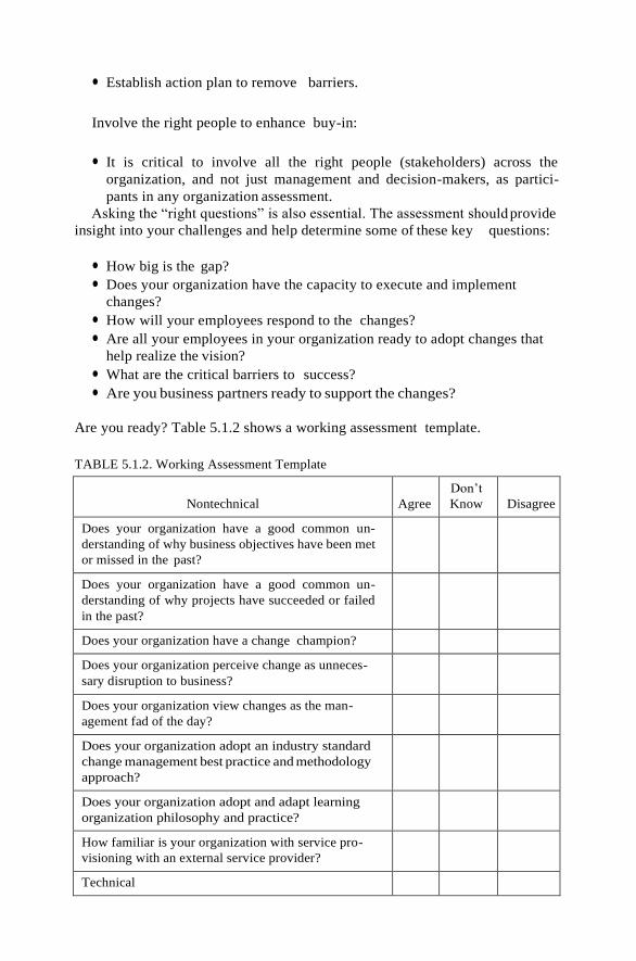
● Establish action plan to remove barriers.
Involve the right people to enhance buy-in:
● It is critical to involve all the right people (stakeholders) across the
organization, and not just management and decision-makers, as partici-
pants in any organization assessment.
Asking the “right questions” is also essential. The assessment should provide
insight into your challenges and help determine some of these key questions:
● How big is the gap?
● Does your organization have the capacity to execute and implement
changes?
● How will your employees respond to the changes?
● Are all your employees in your organization ready to adopt changes that
help realize the vision?
● What are the critical barriers to success?
● Are you business partners ready to support the changes?
Are you ready? Table 5.1.2 shows a working assessment template.
TABLE 5.1.2. Working Assessment Template
Nontechnical
Agree
Don’t
Know
Disagree
Does your organization have a good common un-
derstanding of why business objectives have been met
or missed in the past?
Does your organization have a good common un-
derstanding of why projects have succeeded or failed
in the past?
Does your organization have a change champion?
Does your organization perceive change as unneces-
sary disruption to business?
Does your organization view changes as the man-
agement fad of the day?
Does your organization adopt an industry standard
change management best practice and methodology
approach?
Does your organization adopt and adapt learning
organization philosophy and practice?
How familiar is your organization with service pro-
visioning with an external service provider?
Technical

Does your organization implement any industry
management standards?
● ITIL
● COBIT
● ITSM
● others
Does your organization have a well-established pol-
icy to classify and manage the full lifecycle of all
corporate data?
Can you tell which percentage of your applications is
CPU-intensive, and which percentage of your appli-
cations is data-intensive?
DISCUSSION
Gartner Research has just released the Hype Cycle report for 2009, which
evaluates the maturity of over 1500 technologies and 501 technology
trends.
The report suggests that the cloud computing is the latest growing trend in the
IT industry. According to Gartner Research, cloud computing is expected to
hit the peak of the “inflated expectations” in the next few years. It is expected
that cloud computing data security and integrity issues will be refined over time
as the technology matured. The pay-as-you-go business model will mature with
the technology over time; it will become more transparent and will behave more
like a true utility model, such that you can easily work with a service provider
without worrying about the security of the data. To summarize what we have
learned, one can entertain to leverage the formula developed by management
consultant David Gleicher:
Dissatisfaction 3 Vision of future possibilities 3 Achievable first stepÞ
cResistance to change
This means that any component that is equal to zero or near zero will make the
left-hand side of the equation equal to or approaching zero. In order to make
the change initiative successful, the product of the left-hand side equation must
be a lot greater than that of the right-hand side of the equation (pain or
resistancetochange).
Case Study: ENCANA CORP.
EnCana Corp, Canada’s biggest energy company, announced early Sunday
afternoon—on Mother’s Day—its plans to split into two discrete companies,
an oil company and a natural gas company, in an effort to wring out more
shareholder value with crude prices at record highs. This has all the DNA of the
company’s chairman, David O’Brien: In 2001, under O’Brien’s visionary
leadership, tremendous value was created when CP Limited was split up into
five separate companies and one of them was PanCanadian Petroleum. The
challenge is to quickly establish a corporate culture that would bridge
the somewhat divergent cultures of its two predecessor companies [13, 14].
EnCana, a $65 billion energy producer formed in 2002 in a $27 billion
merger of PanCanadian Petroleum (which focused on oil) and Alberta Energy
Corporation (which focused on gas production), said the move should help
investors better gauge and appreciate the real value of the business of the
respective products and remove a so-called “holding company discount” it
suffers in the stockmarket.
It is expected that the proposed split of EnCana would be similar to the CP
Enterprise split in 2001; the reorganization of EnCana should have the same
impact on the two new companies being created. It should result in (a) better
market valuations because of greater transparency for shareholders and (b)
greater clarity when it comes to allocating capital for expenditures within each
entity.
2008 Highlights (As Published on Their Web Site): Financial (US$)
● Cash flow increased 13% per share to $12.48, or $9.4 billion.
● Operating earnings were up 9% per share to $5.86, or $4.4 billion.
● Net earnings were up 53% per share to $7.91, or $5.9 billion, primarily
due to an after-tax unrealized mark-to-market hedging gain of $1.8 billion
in 2008 compared to an after-tax loss of $811 million in 2007.
● Capital investment, excluding acquisitions and divestitures, was up 17%
to $7.1 billion.
● Generated $2.3 billion of free cash flow (as defined in Note 1 on page 10),
down $112 million from 2007.
● Operating cash flow nearly doubled to $421 million from the company’s
Foster Creek and Christina Lake upstream projects, whereas lower
refining margins and higher purchased product costs resulted in a $241
million loss in operating cash flow for the downstream business. As a
result, EnCana’s integrated oil business venture with ConocoPhillips
generated $180 million of operating cash flow.
In October 2008, EnCana announced that its plan to split into two
companies has been put on hold because of the current global financial crisis:
“The unprecedented uncertainty in the debt and credit markets has certainly
become more difficult and this kind of extraordinary time we’ve decided to
wait,” says Alan Boras, a spokesperson for EnCana.
“However, there is currently too much uncertainty in the global debt and
equity markets to proceed . . . at this time. We cannot predict when the
appropriate financial and market conditions will return, but EnCana will be
prepared to advance the proposed transaction when it determines that the
market conditions are appropriate,” Eresman said.
The discussion questions could be as follows:
1. How would cloud computing be a part of the solution to facilitate the
splitting of the company into two effectively and efficiently and with
minimal disruption to the business?
2. What would you advise EnCana executives to do at the 2008 worldwide

financial market meltdown and the subsequent economic recession?
3. What would your advice be from a business and IT strategic alignment
perspective if you were brought in to advise EnCana IT executives?
4. What were the risks if EnCana went ahead with the split?
5. What were the risks if EnCana put the split onhold?
6. If EnCana is successful in its maneuver, could its peers and competitors
consider splitting their assets into distinct companies to create greater
shareholder value?
7. What IT migration strategy would you recommend EnCana to adopt in
order to achieve the highest flexibility and adaptability to changes?
8. Would you recommend that EnCana buy or build a duplicate IT
infrastructure for each distinct organization as the most efficient way to
align and support the business organization, both the new and the old?
9. Would you recommend cloud computing or utility computing as the
solution to EnCana’s business problem?
10. How would you assess the organizational readiness for EnCana?
11. Would it make any difference if IT can accommodate all the necessary
changes to facilitate the split up of the firm into two distinct entities one-
third of the planned required time?
DATA SECURITY IN THE CLOUD
Taking information and making it secure, so that only yourself or certain
others can see it, is obviously not a new concept. However, it is one that we
have struggled with in both the real world and the digital world. In the real
world, even information under lock and key, is subject to theft and is certainly
open to accidental or malicious misuse. In the digital world, this analogy of
lock-and-key protection of information has persisted, most often in the form of
container-based encryption. But even our digital attempt at protecting infor-
mation has proved less than robust, because of the limitations inherent in
protecting a container rather than in the content of that container. This
limitation has become more evident as we move into the era of cloud
computing: Information in a cloud environment has much more dynamism
and fluidity than information that is static on a desktop or in a network folder,
so we now need to start to think of a new way to protect information.
If we can start off our view of data security as more of a risk mitigation
exercise and build systems that will work with humans (i.e., human-centric),
then perhaps the software we design for securing data in the cloud will be
successful.
THE CURRENT STATE OF DATA SECURITY IN THE CLOUD
At the time of writing, cloud computing is at a tipping point: It has many

arguing for its use because of the improved interoperability and cost savings it
offers. On the other side of the argument are those who are saying that cloud
computing cannot be used in any type of pervasive manner until we resolve the
security issues inherent when we allow a third party to control our information.
These security issues began life by focusing on the securing of access to the
datacenters that cloud-based information resides in.
As I write, the IT industry is beginning to wake up to the idea of content-
centric or information-centric protection, being an inherent part of a data
object. This new view of data security has not developed out of cloud computing,
but instead is a development out of the idea of the “de-perimerization” of
the enterprise. This idea was put forward by a group of Chief Information
Officers (CIOs) who formed an organization called the Jericho Forum .
HOMO SAPIENS AND DIGITAL INFORMATION
Cloud computing offers individuals and organizations a much more fluid and
open way of communicating information. This is a very positive move forward
in communication technology, because it provides a more accurate mimic of the
natural way that information is communicated between individuals and groups
of human beings. Human discourse, including the written word, is, by nature,
an open transaction: I have this snippet of information and I will tell you, verbally
or in written form, what that information is. If the information is sensitive, it may
be whispered, or, if written on paper, passed only to those allowed to read it.
The result is that human-to-human information communication will result in a
very fluid discourse. Cloud computing is a platform for creating the digital
equivalent of this fluid, human-to-human information flow, which is something
that internal computing networks have never quite achieved. In this respect,
cloud computing should be seen as a revolutionary move forward in the use of
technology to enhance human communications.
CLOUD COMPUTING AND DATA SECURITY RISK
Thecloudcomputingmodelopens up oldandnewdatasecurityrisks. Byitsvery
definition, Cloud computing is a development that is meant to allow more open
accessibility and easier and improved data sharing. A user uploading or
creating cloud-based data include those data that are stored and maintained
by a third-party cloud provider such as Google, Amazon, Microsoft, and so on.
This action has several risks associated with it: Firstly, it is necessary to protect
the data during upload into the data center to ensure that the data do not get
hijacked on the way into the database. Secondly, it is necessary to the stores
the data in the data center to ensure that they are encrypted at all times.
Thirdly, andperhaps lessobvious, theaccesstothosedataneedto be controlled;
this control should also be applied to the hosting company, including the
administrators of the data center.
A recent survey by Citrix which polled UK IT directors and managers
showed that two-thirds of UK companies were computing in the cloud. Of
those polled, one-third said they thought there were security risks and 22% said
they had concerns over the control of their data in the cloud .
The development of Web 2.0 technologies has created a new and more
dynamic method of communicating information; blogs, social networking sites,

Web conferencing, wikis, podcasts and ultimately cloud computing itself offer
new and novel methods of getting information from a to b; unfortunately, this
can also often be via x, y, and z.
Compliance with data security directives and acts still needs to be met, no
matter what platform for communication is being used. The lack of security
and privacy within a cloud computing environment is hotly debated over
whether this problem is perceived or real. However, reports by IT industry
analysts suggest that this is a real problem and must be overcome to allow full
utilization of cloud computing. A recent report by IDC which surveyed 244
respondents identified security as the main challenge for cloud computing, with
74.6% of the vote stating this as a stumbling block to the uptake of the
technology . Reports by Gartner and Gigacom, specifically on cloud security,
also confirms this [9, 10].
We can thus conclude that the risk profile of an organization, or individual,
using the cloud to store, manage, distribute, and share its information has
several layers. Each layer can be seen as a separate, but tied, level of risk that
can be viewed independently, but these risks should be approached as a whole,
to make sure that areas constituting a “weakest link” do not end up built into
the system.
CLOUD COMPUTING AND IDENTITY
Digital identity holds the key to flexible data security within a cloud environ-
ment. This is a bold statement, but nonetheless appears to be the method of
choice by a number of industry leaders. However, as well as being a perceived
panacea for the ills of data security, it is also one of the most difficult
technological methods to get right. Identity, of all the components of informa-
tion technology, is perhaps the most closest to the heart of the individual. After
all, our identity is our most personal possession and a digital identity represents
who we are and how we interact with others on-line.
The developments seen in the area of a cloud-based digital identity layer
have been focused on creating a “user-centric” identity mechanism. User-
centric identity, as opposed to enterprise-centric identity, is a laudable design
goal for something that is ultimately owned by the user. However, the Internet
tenet of “I am who I say I am” cannot support the security requirements of a
data protection methodology based on digital identity, therefore digital identity,
in the context of a security system backbone, must be a verified identity by
some trusted third party: It is worth noting that even if your identity is verified
by a trusted host, it can still be under an individual’s management and control.
Identity, Reputation, and Trust
One of the other less considered areas of digital identity is the link between the
identity and the reputation of the individual identity owner. Reputation is a
real-world commodity that is a basic requirement of human-to-human relation-
ships: Our basic societal communication structure is built upon the idea of
reputation and trust. Reputation and its counter value, trust, is easily
transferable to a digital realm: eBay, for example, having partly built a
successful business model on the strength of a ratings system, builds up the

reputation of its buyers and sellers through successful (or unsuccessful)
transactions. These types of reputation systems can be extremely useful when
used with a digital identity. They can be used to associate varying levels of trust
with that identity, which in turn can be used to define the level (granular
variations) of security policy applied to data resources that the individual
wishes to access.
Identity for Identity’s Sake
An aspect of identity that again is part of our real world and needs to be
mimicked in the digital world is that of “multiple identities,” because in the
cloud you may find that you need a different “identity” or set of identifiers to
access resources or perform different tasks.
Cloud Identity: User-Centric and Open-Identity Systems
As the use of the Internet and cloud computing increases, the risks associated
with identifying yourself, via this medium, have also increased. Identity fraud
and theft are a real threat to the uptake and acceptance of cloud computing;
and as already stated, a robust digital identity can be the backbone of data
security in the cloud.
Internet identities such as information cards were originally designed to
overcome the problem of “password fatigue,” which is an increasing problem
for users needing to remember multiple log-on credentials for Web site access.
Similarly, OpenID was developed for the purpose of an easier logon into
multiple Web sites, negating the need to remember username/logon creden-
tials. Information cards differ from OpenID in a fundamental manner in that
information cards have an architecture built on the principle of “claims,”
claims being pieces of information that can be used to identify the card holder.
At this juncture it is worth pointing out that, although OpenID can use claims,
the architecture behind OpenID makes this use of claims less flexible—and,
more importantly, less dynamic in nature—than those offered by information
cards.
The Philosophy of User-Centric Identity
Digital identities are a still evolving mechanism for identifying an individual,
particularly within a cloud environment; and, as such, the philosophy behind
the idea is also still being formed. However, one area that is being recognized as
a basic component of an identity is that of identity ownership being placed upon
the individual (user-centric). Placing ownership with an individual then sets in
place a protocol around the use of the identity.
User-Centric but Manageable
In situations that require a degree of nonrepudiation and verification, where a
user is who they say they are—that is, situations that require a digital identity
to provide access control and security—user-centric identities can still be under
user control and thus user-centric (the user choosing which identity and which
identity claims to send across a transaction path) but must be issued and

managed by a trusted host able to verify the user (for example, the users bank).
This may seem like a security paradox, but it is actually a balanced way of
using a digital identity to assign security policies and control while retaining a
high measure of privacy and user choice.
What Is an Information Card?
Information cards permit a user to present to a Web site or other service
(relying party) one or more claims, in the form of a software token, which may
be used to uniquely identify that user. They can be used in place of user name/
passwords, digital certificates, and other identification systems, when user
identity needs to be established to control access to a Web site or other
resource, or to permit digital signing.
Information cards are part of an identity meta-system consisting of:
1. Identity providers (IdP), who provision and manage information cards,
with specific claims, to users.
2. Users who own and utilize the cards to gain access to Web sites and other
resources that support information cards.
3. An identity selector/service, which is a piece of software on the user’s
desktop or in the cloud that allows a user to select and manage their
cards.
4. Relying parties. These are the applications, services, and so on, that can
use an information card to authenticate a person and to then authorize an
action such as logging onto a Web site, accessing a document, signing
content, and so on.
Each information card is associated with a set of claims which can be used to
identify the user. These claims include identifiers such as name, email address,
post code, and so on. Almost any information may be used as a claim, if
supported by the identity provider/relying party; for example, a security
clearance level could be used as a claim, as well as a method of assigning a
security policy.
One of the most positive aspects of an information card is the user-centric
nature of the card. An information card IdP can be set up so that the end
users themselves can self-issue a card, based on the required claims that they
themselves input—the claims being validated if needed. Alternatively, the
claims can be programmatically input by the IdP via a Web service or similar,
allowing the end user to simply enter the information card site and download
the card.
Using Information Cards to Protect Data
Information cards are built around a set of open standards devised by a
consortium that includes Microsoft, IBM, Novell, and so on.
The original remit of the cards was to create a type of single sign on system
for the Internet, to help users to move away from the need to remember
multiple passwords. However, the information card system can be used in many
more ways. Because an information card is a type of digital identity, it can be

used in the same way that other digital identities can be used. For example, an
information card can be used to digitally sign data and content and to control
access to data and content. One of the more sophisticated uses of an
information card is the advantage given to the cards by way of the claims
system. Claims are the building blocks of the card and are dynamic in that they
can be changed either manually or programmatically, and this
change occurs in real time: As soon as the change is made, it can be
reflected when the card is used, for example, by a subsequent
change in the access or content usage policy of the resource
requiring the information card. This feature can be used by
applications that rely on the claims within an information card to
perform a task (such as control access to a cloud-based data
resource such as a document). A security policy could be applied to
a data resource that will be enacted when a specific information card
claim is presented to it: If this claim changes, the policy can
subsequently change.
For example, a policy could be applied to a Google Apps document
specifying that access is allowed for user A when they present their information
card with claim “security clearance level 5 3” and that post access, this user
will be able to view this document for 5 days and be allowed to edit it. The same
policy could also reflect a different security setting if the claim changes, say to a
security clearance level 5 1; in this instance the user could be disallowed access
or allowed access with very limited usage rights.
Weakness and Strengths of Information Cards
The dynamic nature of information cards is the strength of the system, but the
weakness of information cards lies in the authentication. The current informa-
tion card identity provisioning services on offer include Microsoft Geneva,
Parity, Azigo, Higgins Project, Bandit, and Avoco Secure. Each offers varying
levels of card authentication and are chosen from Username and password,
Kerberos token, x509 digital certificate, and personal card. Each of these
methods has drawbacks.
Cross-Border Aspects of Information Cards
Cloud computing brings with it certain problems that are specific to a widely
distributed computing system. These problems stem from the cross-border
nature of cloud computing and the types of compliance issues arising out of
such a situation.
The use of information cards as a method of digitally identifying an
individual within the cloud (as well as on the desktop) will gain ground, as
its usage model extends with increased support for information cards, from
relying parties and as usability through the use of cloud-based selectors
becomes more mainstream.

THE CLOUD, DIGITAL IDENTITY, AND DATA SECURITY
When we look at protecting data, irrespective of whether that protection is
achieved on a desktop, on a network drive, on a remote laptop, or in a cloud,
we need to remember certain things about data and human beings. Data are
most often information that needs to be used; it may be unfinished and require
to be passed through several hands for collaboration for completion, or it could
be a finished document needing to be sent onto many organizations and then
passed through multiple users to inform. It may also be part of an elaborate
workflow, across multiple document management systems, working on plat-
forms that cross the desktop and cloud domain. Ultimately, that information
may end up in storage in a data center on a third-party server within the cloud,
but even then it is likely to be re-used from time to time. This means that the
idea of “static” data is not entirely true and it is much better (certainly in terms
of securing that data) to think of it as highly fluid, but intermittently static. One of the other aspects of data security we need to assess before embarking
on creating a security model for data in the cloud is the levels of need; that is,
how secure do you want that data to be? The levels of security of any data
object should be thought of as concentric layers of increasingly pervasive
security, which I have broken down here into their component parts to show
the increasing granularity of this pervasiveness:
Level 1: Transmission of the file using encryption protocols
Level 2: Access control to the file itself, but without encryption of the content
Level 3: Access control (including encryption of the content of a data object)
Level 4: Access control (including encryption of the content of a data object)
also including rights management options (for example, no copying
content, no printing content, date restrictions, etc.)
Other options that can be included in securing data could also include
watermarking or red-acting of content, but these would come under level 4
above as additional options.
You can see from the increasing granularity laid out here that security,
especially within highly distributed environments like cloud computing, is not
an on/off scenario. This way of thinking about security is crucial to the
successful creation of cloud security models. Content level application of data
security gives you the opportunity to ensure that all four levels can be met by a
single architecture, instead of multiple models of operation which can cause
interoperability issues and, as previously mentioned, can add additional
elements of human error, leading to loss of security.
CONTENT LEVEL SECURITY—PROS AND CONS
Much of the substance of this chapter has described a new way of thinking
about securing data, so that data within a cloud can remain fluid, accessible on
multiple nodes and yet remain protected throughout its life cycle. The basis of
this new security model has been described as “content or information-centric.”
What this means in reality is that the content that makes up any given data
object (for example, a Word document) is protected, as opposed to the file—
that is, the carrier of that information being protected. This subtle difference in
approach gives us a major advantage in terms of granularity and choice of
protection level, as well as persistence of protection. We will take a Word
document as our example here to outline the main pros and cons of this type of
security approach.
You can easily see the advantages that are conferred on data protected at the
content level: greater control, more focused access control, increased granular
protection over content, and assurance within a cloud-hosted system. But what,
if any, disadvantages come with this type of methodology?
Transfer of the data between application and database, or human-to-human
transfer, can protect the data as an encrypted package, decrypted when access is
granted. Content-centric security measures need to be compatible with both
database security and secure transfer of data within a cloud environment.
Protecting the content of our Word document needs to be done in such a
manner that it does not impact the storage of that data.
FUTURE RESEARCH DIRECTIONS
This chapter has spent some time discussing digital identity within a cloud
framework. The reason for this emphasis was to show the possibilities that can
be achieved, in terms of data security, when using digital identity as the
backbone for that security. Digital identity is an area that is, as I write,
undergoing some revolutionary changes in what an identity stands for and how
it can be leveraged. As a means of controlling access to information within a
cloud environment, the idea of using a person’s digital identity to do this, as
opposed to using authentication alone, or some sort of access control list setup,
opens up new opportunities, not only from a technological standpoint but also
from the viewpoint that ownership of information and privacy of that
information are often inherently linked to individuals and groups. And, as
such, how they access this information becomes much more natural when that
access is by means of truly and digitally identifying themselves.
Currently there are methods of creating more private identity transactions
which can hide or obfuscate an identity attribute (a social security number, for
example) such as zero-knowledge technology (sometimes called minimal
disclosure) or similar Privacy Enhancing Technologies (PETs) ; however, these
methods are still not used in a pervasive manner, and this may be because of
the need to build more user control into the technologies and to add greater
granularity into such systems.
Another area that warrants research is auditing of the access to and use of
information in the cloud. In particular, because of the cross-border nature of
cloud computing, there is likely to be a greater need for location-aware security
restrictions to be used. However, one area that does need further work is that of
locking data access to a geographic location. How that geographic location is
assessed is the salient area for research, because currently GPS systems are little
used and come with inherent technical difficulties such as the ability to receive
GPS coordinates when inside a building.

LEGAL ISSUES IN CLOUD COMPUTING
“Even before the blades in the data center went down, I knew we had a
problem. That little warning voice in the back of my head had become an
ambulance siren screaming right into my ears. We had all our customers’
applications and data in there, everything from the trivial to the mission
critical. I mumbled one of those prayers that only God and IT types hear,
hoping our decisions on redundancy were the right ones. We had a disaster
recovery plan, but it had never really been battle-tested. Now we were in
trouble; and the viability of not just our enterprise, but also that of many of our
customers, hung in the balance. I can take the hits associated with my own
business, but when someone else’s business could sink... it’s different.
I looked over at Mike and Nihkil, our resident miracle workers. The color
had drained from both of their faces. ‘I’ve given you all she’s got, Captain,’
Nikhil said in his best Scotty from Star Trek voice. Looking over at Mike and
sinking even lower into my seat, I knew it was going to be a long and painful
day... .”
Definition of Cloud Computing
This chapter assumes that the reader is familiar with the manner in which cloud
computing is defined as set forth by the National Institute of Standards and
Technology , a federal agency of the United States Government.
In brief, cloud computing is a model for enabling convenient, on-demand
network access to a shared pool of configurable computing resources (e.g.,
networks, servers, storage, applications, and services) that can be rapidly
provisioned and released. This cloud model is composed of five essential
characteristics, three service models, and four deployment models.
Overview of Legal Issues
The legal issues that arise in cloud computing are wide ranging. Significant
issues regarding privacy of data and data security exist, specifically as they
relate to protecting personally identifiable information of individuals, but also
as they relate to protection of sensitive and potentially confidential business
information either directly accessible through or gleaned from the cloud
systems (e.g., identification of a company’s customer by evaluating traffic
across the network). Additionally, there are multiple contracting models under
which cloud services may be offered to customers (e.g., licensing, service
agreements, on-line agreements, etc. Finally, commercial and business
considerations require some attention. What happens to customer
information, applications, and data when a cloud provider is acquired? What
are the implications for that same set of informa- tion, applications, and data
when a cloud provider is files bankruptcy or ceases to do business? All of these
issues will be explored.

Distinguishing Cloud Computing from Outsourcing and
Provision of Application Services
Cloud computing is different from traditional outsourcing and the application
service provider (ASP) model in the following ways:
● In general, outsourcers tend to take an entire business or IT process of a
customer organization and completely run the business for the benefit of
the customer.
● In the ASP model, the service provided is a software service. The software
application may have been used previously in-house by the customer, or it
may be a new value-added offering. The ASP offering is a precursor to
what is now called “software as a service.” The transaction is negotiated,
though typically it is not as complex and highly negotiated as a traditional
outsourcing arrangement.
● Cloud computing covers multiple service models (i.e, software, infrastruc-
ture, and platform as a service). As of this writing, access to cloud
computing services are (at least in the public cloud computing frame-
work), for the most part, one-size-fits-all ‘click here to accept’ agreements,
not negotiated arrangements.
DATA PRIVACY AND SECURITY ISSUES
U.S. Data Breach Notification Requirements
Generally speaking, data breach is a loss of unencrypted electronically stored
personal information. This information is usually some combination of name
and financial information (e.g., credit card number, Social Security Number).
Almost all 50 states in the United States now require notification of affected
persons (i.e., residents of the individual state), upon the occurrence of a data
breach. As of this writing, the European Union was considering data breach
legislation.
Federal Law Compliance
Gramm—Leach—Bliley Act: Financial Privacy Rule. The Gramm— Leach—
Bliley Act (GLB) requires, among other things, that financial institutions
implement procedures to ensure the confidentiality of personal information and
to protect against unauthorized access to the information. Various United
States government agencies are charged with enforcing GLB, and those agencies
have implemented and currently enforce standards .
The implications to the cloud provider that is providing services to financial
institutions are that the cloud provider will, to some degree, have to (1) comply
with the relevant portions of GLB by demonstrating how it prevents un-
authorized access to information, (2) contractually agree to prevent unauthor-
ized access, or (3) both of the above.

The Role of the FTC: Safeguards Rule and Red Flags Rule. At the
United States federal level, the Federal Trade Commission (FTC) working
under the auspices of the FTC Act has been given authority to protect
consumers and their personal information. The Safeguards Rule mandated by
GLB and enforced by the FTC requires that all businesses significantly
involved in the provision of financial services and products have a written
security plan to protect customer information. The plan must include the
following elements :
● Designation of one or more employees to coordinate its information
security program;
● Identification and assessment of the risks to customer information in each
relevant area of the company’s operation, and evaluation of the effective-
ness of the current safeguards for controlling these risks;
● Designing and implementing a safeguards program, and regularly mon-
itoring and testing it;
● Selection of service providers that can maintain appropriate safeguards;
and
● Evaluation and adjustment of the program in light of relevant circum-
stances, including (a) changes in the firm’s business or operations or
(a) the results of security testing and monitoring.
In 2007, as part of the Fair and Accurate Credit Transaction Act of 2003
(FACT) , the FTC promulgated the Red Flag Rules1
(these rules were
scheduled to go into effect in November 2009, but have been delayed several
times). These rules are intended to curb identity theft by having financial
institutions identify potential “red flags” for activities conducted through the
organization’s systems that could lead to identity theft.
Health Insurance Portability and Accountability Act & HITECH Act. The
Health Information Technology for Economic and Clinical Health Act
(HITECH ACT) requires notification of a breach of unencrypted health
records (similar to that under state data breach notification requirements
previously discussed) for all covered entitites that are required to comply with
the Health insurance Portability and Accountability Act of 1996 (HIPAA) .
USA PATRIOT Act. Shortly after September 11, 2001, the United States
Congress passed the “Uniting and Strengthening America by Providing
Appropriate Tools Required to Intercept and Obstruct Terrorism Act” (USA
PATRIOT Act) of 2001. Neither the cloud user nor its customer likely has
much recourse in such an instance.
International Data Privacy Compliance
European Union Data Privacy Directive. In 1995, the European Union
(EU) passed the “European Union Directive on the Protection of Individuals
with Regard to the Processing of Personal Data and the Movement of Such
Data Privacy Directive”(Directive)

Article 17 of the Directive requires that a data controller (i.e., the person or
organization who determines the purposes and means of processing of the
personal data) “implement appropriate technical and organizational controls to
protect personal data against accidental or unlawful destruction or acci- dental
loss, alteration, unauthorized disclosure or access... .” Article 17 also mandates
that there be a written contract between a data controller and a data processor
(i.e., anyone who processes data for the controller) that requires, among other
things, that the data processor act only on instructions from the data controller.
Since a cloud provider will likely be a data processor, Article 17 is particularly
important. The language of the cloud provider’s contract is also particularly
important if the cloud provider resides in the EU.
If a cloud provider wishes to conduct business in the EU, place data in its
possession in the EU, or otherwise access the personal information of those in
the EU, there are compliance obligations under the Directive that must be
studied and followed. The cloud user must ask questions regarding geographic
placement of data, compliance methods, and so on, and get satisfactory
answers prior to placing its personal data (whether through software, platform,
or infrastructure as a service) into a cloud that might include data center
operations in an EU member country.
A Sampling of Other Jurisdictions: Canada and Australia. Many coun-
tries have data protection or data privacy regimes in place, but the coverage
and effect of such regimes is varied. For example, Argentina’s regime is similar
to the EU approach. Brazil, like many countries, has a constitutional right to
privacy.
Canada’s Personal Information Protection and Electronic Documents Act
(PIPEDA). PIPEDA is intended to “support and promote electronic commerce
by protecting personal information that is collected, used, or disclosed in
certain circumstances.. .” . Canada, unlike the EU with its state-to-state
approach, has taken an organization-to-organization approach to privacy. In
essence, organizations are held accountable for the protection of personal
information it transfers to third parties, whether such parties are inside or
outside of Canada.
Australia Privacy Act. Australia’s Privacy Act is based on (a) 11 “In-
formation Privacy Principles” that apply to the public sector and (b) 10
“National Privacy Principles” that apply to the private sector. Australian
entities may send personal data abroad, so long as (1) the entity believes the
recipient will uphold the principles, it has consent from the data subject, or (3)
the transfer is necessary to comply with contractual obligations.
The Office of the Privacy Commissioner expects that Australian organiza-
tions will ensure that cloud providers that collect and handle personal
information comply with National Privacy Principles 4 and 9. They require
that an organization (1) take steps to ensure that the personal information it
holds is accurate, up-to-date, and secure and (2) protect personal information
that it transfers outside Australia.

CLOUD CONTRACTING MODELS
Licensing Agreements Versus Services Agreements
Summary of Terms of a License Agreement. A traditional software license
agreement is used when a licensor is providing a copy of software to a licensee for
its use (which is usually non-exclusive). This copy is not being sold or transferred
to the licensee, but a physical copy is being conveyed to the licensee. The software
license is important because it sets forth the terms under which the software may
be used by the licensee. The license protects the licensor against the inadvertent
transfer of ownership of the software to the person or company that holds the
copy. It also provides a mechanism for the licensor of the software to (among
other things) retrieve the copy it provided to the licensee in the event that the
licensee (a) stops complying with the terms of the license agreement or (b) stops
paying the fee the licensee charges for the license.
Summary of Terms of a Service Agreement. A service agreement, on the
other hand, is not designed to protect against the perils of providing a copy of
software to a user. It is primarily designed to provide the terms under which a
service can be accessed or used by a customer. The service agreement may also set
forth quality parameters around which the service will be provided to the users.
Value of Using a Service Agreement in Cloud Arrangements. In each of
the three permutations of cloud computing (SaaS, PaaS, and IaaS), the access
to the cloud-based technology is provided as a service to the cloud user. The
control and access points are provided by the cloud provider.
On-Line Agreements Versus Standard Contracts
There are two contracting models under which a cloud provider will grant
access to its services. The first, the on-line agreement, is a click wrap agreement
with which a cloud user will be presented before initially accessing the service. A
click wrap is the agreement the user enters into when he/she checks an “I Agree”
box, or something similar at the initiation of the service relationship. The
agreement is not subject to negotiation and is generally thought to be a contract
of adhesion (i.e., a contract that heavily restricts one party while leaving the
other relatively free).
The Importance of Privacy Policies Terms and Conditions
The privacy policy of a cloud provider is an important contractual document
for the cloud user to read and understand. Why? In its privacy policy the cloud
provider will discuss, in some detail, what it is doing (or not doing, as the case
may be) to protect and secure the personal information of a cloud user and its
customers.
The cloud provider should be explicit in its privacy policy and fully describe
what privacy security, safety mechanisms, and safety features it is implement-
ing. As further incentive for the cloud provider to employ a “do what we say we
do” approach to the privacy policy, the privacy policy is usually where the FTC
begins its review of a company’s privacy practices as part of its enforcement
actions. If the FTC discovers anomalies between a provider’s practices and its
policies, then sanctions and consent decrees may follow.
Risk Allocation and Limitations of Liability. Simply stated, the limitation
of liability in an agreement sets forth the maximum amount the parties will
agree to pay one another should there be a reason to bring some sort of legal
claim under the agreement. The cloud user will pay a fee premium for shifting
the liability and contractual risk to the cloud provider. The cloud provider’s
challenge, as it sees the risk and liability profile shift requiring it to assume
heightened provider obligations, will be to appropriately mitigate contract risk
using technological or other types of solutions where possible. Examples of
mitigation could include implementation of robust and demonstrable informa-
tion security programs, implementing standards or best practices, developing
next generation security protocols, and enhancing employee training.
JURISDICTIONAL ISSUES RAISED BY VIRTUALIZATION AND DATA
LOCATION
Jurisdiction is defined as a court’s authority to judge acts committed in a certain
territory. The geographical location of the data in a cloud computing
environment will have a significant impact on the legal requirements for
protection and handling of the data. This section highlights those issues.
Virtualization and Multi-tenancy
Virtualization. Computer virtualization in its simplest form is where one
physical server simulates being several separate servers. For example, in an
enterprisesetting, insteadofhavingasingleserverdedicatedtopayrollsystems,
another one dedicated to sales support systems, and still a third dedicated to
asset management systems, virtualization allows one server to handle all of
these functions. A single server can simulate being all three. Each one of these
simulated servers is called a virtual machine.
Virtualization across a single or multiple data centers makes it difficult for
the cloud user or the cloud provider to know what information is housed on
various machines at any given time. The emphasis in the virtualized environ-
ment is on maximizing usage of available resources no matter where they reside.
Multi-tenancy. Multi-tenancy refers to the ability of a cloud provider to
deliver software as-a-service solutions to multiple client organizations (or
tenants) from a single, shared instance of the software. The cloud user’s
information is virtually, not physically, separated from other users. The major
benefit of this model is cost-effectiveness for the cloud provider. Some risks or
issues with the model for the cloud user include (a) the potential for one user to
be able to access data belonging to another user and (b) difficulty to back up
and restore data .
The Issues Associated with the Flexibility of Data-Location
One of the benefits of cloud computing from the cloud provider’s perspective is
the ability of the cloud provider to move data among its available data center
resources as necessary to maximize the efficiencies of it overall system. From a
technology perspective, this ability to move data is a reasonably good solution
to the problem of under utilized machines.
Data Protection. In fact, in the cloud environment it is possible that the same
data may be stored in multiple locations at the same time. For example, real
time-transaction data may be in one geographic location while the backup or
disaster recovery systems may be elsewhere. It is also likely that the agreement
governing the services says nothing about data location. There are exceptions,
however. In fact, a few cloud providers (of which Amazon.com is one) are
allowing cloud customers of certain service offerings to choose whether their
data are kept in a U.S. or European data center .
Examples of the issues raised by data location are highlighted by Robert
Gellman of the World Privacy Forum:
The European Union’s Data Protection Directive offers an example of the
importance of location on legal rights and obligations. Under Article 4 . . . [O]nce
EU law applies to the personal data, the data remains subject to the law, and the
export of that data will thereafter be subject to EU rules limiting transfers to a third
country. Once an EU Member State’s data protection law attaches to personal
information, thereisnoclearway to removetheapplicabilityofthelawto thedata .
Other Jurisdiction Issues
Confidentiality and Government Access to Data. Each jurisdiction (and
perhaps states or provinces within a jurisdiction) has its own regime to protect
the confidentiality of information. In the cloud environment, given the
potential movement of data among multiple jurisdictions, the data housed in
a jurisdiction is subject to the laws of that jurisdiction, even if its owner resides
elsewhere. Given the inconsistency of confidentiality protection in various
jurisdictions, a cloud user may find that its sensitive data are not entitled to the
protection with which the cloud user may be familiar, or that to which it
contractually agreed.
Subcontracting. A cloud provider’s use of a third-party subcontractor to
carry out its business may also create jurisdictional issues. The existence or
nature of a subcontracting relationship is most likely invisible to the cloud user.
International Conflicts of Laws
The body of law known as “conflict of laws” acknowledges that the laws of
different countries may operate in opposition to each other, even as those laws
relate to the same subject matter. In such an event, it is necessary to decide
which country’s law will be applied.
In a cloud environment, the conflicts of laws issues make the cloud provider’s
decisions regarding cross-geography virtualization and multi-tenancy, the cloud
user’s lack of information regarding data location, and the potential issues with
geographically diverse subcontractors highly relevant.
COMMERCIAL AND BUSINESS CONSIDERATIONS—A CLOUD USER’S
VIEWPOINT
As potential cloud users assess whether to utilize cloud computing, there
are several commercial and business considerations that may influence the
decision-making. Many of the considerations presented below may manifest in
the contractual arrangements between the cloud provider and cloud user.
Minimizing Risk
Maintaining Data Integrity. Data integrity ensures that data at rest are not
subject to corruption. Multi-tenancy is a core technological approach to
creating efficiencies in the cloud, but the technology, if implemented or
maintained improperly, can put a cloud user’s data at risk of corruption,
contamination, or unauthorized access. A cloud user should expect contractual
provisions obligating a cloud provider to protect its data, and the user
ultimately may be entitled to some sort of contract remedy if data integrity is
not maintained.
Accessibility and Availability of Data/SLAs. The service-level agreement
(SLA) is the cloud provider’s contractually agreed-to level of performance for
certain aspects of the services. The SLA, specifically as it relates to availability
of services and data, should be high (i.e., better than 99.7%), with minimal
scheduled downtime (scheduled downtime is outside the SLA). Regardless of
the contract terms, the cloud user should get a clear understanding of the cloud
provider’s performance record regarding accessibility and availability of
services and data. A cloud provider’s long-term viability will be connected to
its ability to provide its customers with almost continual access to their services
and data. The SLAs, along with remedies for failure to meet them (e.g., credits
against fees), are typically in the agreement between the cloud provider and
cloud user.
Disaster Recovery. For the cloud user that has outsourced the processing of
its data to a cloud provider, a relevant question is, What is the cloud provider’s
disaster recovery plan? What happens when the unanticipated, catastrophic
eventaffectsthedatacenter(s) wherethecloudservicesarebeingprovided? Itis
important for both parties to have an understanding of the cloud provider’s
disasterrecovery plan.
Viability of the Cloud Provider
In light of the wide diversity of companies offering cloud services, from early
stage and startup companies to global, publicly traded companies, the cloud
provider’s ability to survive as business is an important consideration for the
cloud user. A potential cloud user should seek to get some understanding about
the viability of the cloud provider, particularly early-stage cloud providers.

Why is this important? A cloud user will make an investment in (1)
integrating the cloud services into its business processes and (2) migrating the
data from its environment into the cloud environment.
Does Escrow Help?. Software escrow is the provision of a copy of the source
code by the owner or licensor of the source code to a neutral third party (an
escrow agent) for safekeeping for the benefit of a licensee or user of the code
(the user is a beneficiary). The escrow agent releases the software to the
beneficiary upon the occurrence of certain predefined events—for example,
bankruptcy of the owner. So, at least for SaaS cloud users, escrow is an option.
But escrow is not available to the cloud user unless expressly offered by the
cloud provider in its agreement.
What is a cloud user to do? Assuming that the cloud user has some flexibility
to negotiate contract terms, the reasoned approach is for the cloud user to get
contractual assurances that in the event of cessation of business, or some lesser
event (e.g., bankruptcy), it will at least have access to its data and information
without penalty or without being subject to the bankruptcy laws of a
jurisdiction as a prerequisite. If the contract does not provide such a right, a
user must determine whether to simply run the risk regarding the provider’s
viability. Equally as important, the cloud user should consider having a
business continuity plan that contemplates a cloud provider no longer being
able to provide a service.
Protecting a Cloud User’s Access to Its Data
Though the ability for the cloud user to have continual access to the cloud
service is a top consideration, a close second, at least from a business continuity
standpoint, is keeping access to its data. This section introduces three scenarios
that a cloud user should contemplate when placing its data into the cloud.
There are no clear answers in any scenario. The most conservative or risk-
averse cloud user may consider having a plan to keep a copy of its cloud-stored
dataset in a location not affiliated with the cloud provider.
Scenario 1: Cloud Provider Files for Bankruptcy. In a bankruptcy
proceeding, data are treated as a non-intellectual asset and under Section 363
of the U.S. Bankruptcy Code, and it is subject to disposition in a manner
similar to other non-intellectual assets. Data may be consumer-type data, or it
may be the business-level transaction data of the bankrupt cloud provider’s
business customers.
The cloud user is probably equally concerned about keeping its data
(regardless of type) private and out of third-party hands without its consent.
The cloud user’s options are closely tied to the language of the privacy policy of
the cloud provider. That language, along with an analysis by a “consumer
privacy ombudsman,” if one is appointed, will likely determine the fate of
personally identifiable information. The ombudsman uses a multi-factor
assessment that includes a review of (a) the potential gains or losses to
consumers if the sale was approved and (b) potential mitigating alternatives.6
Any transfer is likely to be under privacy terms similar to those of the cloud
provider. There is no equivalent analysis undertaken by the ombudsman for

business-level transaction data. Business data are likely to be handled at the will
of the bankruptcy court. The good news is that a cloud user probably will not
lose access to its data. However, a third-party suitor to the bankrupt cloud
provider may gain access to such data in the process.
Scenario 2: Cloud Provider Merges or Is Acquired. Any number of
situations could lead to the transfer of the cloud provider’s operation and
the information associated with it, to a third party. The most likely scenarios
include the merger or acquisition of the business, or the sale of a business unit
or service line. Since a cloud user is unlikely to be notified prior to the closing of
a transaction, once again the privacy policy is the best place to look to
determine what would happen to user data in such an event. The click wrap
agreement will clarify the termination options available to the cloud user
should it be dissatisfied with the new ownership.
Scenario 3: Cloud Provider Ceases to Do Business. As a best case, if
there is an orderly shutdown of a cloud provider as part of its cessation
activities, the cloud user may have the ability to retrieve its data as
part of the shut-down activities. In the event that a cloud provider simply walks away and shuts down the business, cloud users are most
likely left with only legal remedies, filing suit, for example, to attempt to get access to its data.
SPECIAL TOPICS
The Cloud Open-Source Movement
In Spring 2009 a group of companies, both technology companies and users of
technology, released the Open Cloud Manifesto [25]. The manifesto’s basic
premise is that cloud computing should be as open like other IT technologies.
The manifesto sets forth five challenges that it suggests must be overcome
before the value of cloud computing can be maximized in the marketplace.
These challenges are (1) security, (2) data and applications interoperability,
(2) data and applications portability, (4) governance and management, and
(5) metering and monitoring. The manifesto suggests that open standards and
transparency are methods to overcome these challenges. It then suggests that
openness will benefit business by providing (a) an easier experience transition-
ing to a new provider, (b) the ability for organizations to work together,
(b) speed and ease of integration, and (d) a more available, cloud-savvy talent
pool from which to hire.
Litigation Issues/e-Discovery
From a U.S. law perspective, a significant effort must be made during the
course of litigation to produce electronically stored information (ESI). This
production of ESI is called “e-discovery.” The overall e-discovery process has
three basic components: (1) information management, where a company
decides where and how its information is processed and retained, (2) identify-
ing, preserving, collecting, and processing ESI once litigation has been

threatened or started, and (3) review, processing, analysis, and production of
the ESI for opposing counsel [26]. The Federal Rules of Civil Procedure require
a party to produce information within its “possession, custody, or control.”
Courts will likely recognize that the ESI may not be within a cloud user’s
possession, but courts will suggest, and maybe assume, that ESI is within its
control.
ACHIEVING PRODUCTION READINESS FOR
CLOUD SERVICES
The latest paradigm that has emerged is that of cloud computing where new
evolution of operating model enables IT services to be delivered through next-
generation data-center infrastructures consisting of compute, storage, applica-
tions and databases, built over virtualization technology .
Cloud service providers who are planning to build infrastructure to support
cloud services should first justify their plans through a strategic and business
planning process. Designing, building, implementing, and commissioning an
underlying technology infrastructure to offer cloud services to a target market
segment is merely a transformation process that the service provider must
undertake to prepare for supporting the processes, management tools, technol-
ogy architectures, and foundation to deliver and support their cloud services.
These foundation elements will be used to produce the cloud service that will
be ready for consumption.
SERVICE MANAGEMENT
The term service management has been defined in many ways by analysts and
business practitioners.
The Stationery Office defines service management as follows:
Service management is more than just a set of capabilities. It is also a professional
practice supported by an extensive body of knowledge, experience, and skill.
Van Bon et al. and van der Veen describe service management as:
The capacity of an organization to deliver services to customers.
Based on analysis and research of service management definitions, we define
service management as a set of specialized organizational capabilities for
providing value to customers in the form of services. The practice of service
management have expanded over time, from traditional value-added service
such as banks, hotels, and airlines into IT provider model that intends to adopt
service-oriented approach in managing and delivering IT services.
This delivery model of IT services to the masses, where assets, resources, and

capabilities are pooled together, is what we would term a form of cloud service.
The lure of cloud services is its ubiquity, pervasiveness, elasticity, and flexibility
of paying only for what you use.
PRODUCER—CONSUMER RELATIONSHIP
As we contemplate on the new paradigm of delivering services, we can reflect
upon the closely knit underlying concept of the classical producer—consumer
relationship in the design, implementation, and production of the service as
well as in the consumption of the service. The producer—consumer relationship
diagram is shown in Figure 5.4.1.
The producer, also known as cloud service provider, refers to the party who
strategizes, designs, invests, implements, transitions, and operates the under-
lying infrastructure that supplies the assets and resources to be delivered as a
cloud service. The objective of the producer is to provide value-add as a cloud
service, which will deliver value to their customers by facilitating outcomes
customers want to achieve.
The consumer does not want to be accountable for all associated costs and
risks, real or nominal, actual or perceived, such as
FIGURE 5.4.1. The producer—consumer relationship diagram.
designing the technology architectures, management tools, processes, and all
the resources to manage, deliver, and support the service.
The law of demand and supply will provide an efficient ecosystem in which
the consumer with specific needs will be able to locate and find available service
providers in the market that meet the required service demands and at the right
price.
Business Mindset
Broker/
Agent
Wholesaler/
Distributor
Producer/ Service Provider
Indirect Direct
Consumer
Retailer/
Dealer

• Market Recommendation
• Customer Needs
• Value of Service
Expected
Quality
Quality of Service/
Perceived Quality
From a producer’s perspective, it is critical to understand what would be the
right and desired outcome. Rather than focusing on the production of services,
it is important to view from the customer’s perspective. In order for producers
to provide the desired cloud services, some of the questions that the service
provider should address are:
● Nature of business (What is the core business?)
● Target consumer segments (Who are the customers?)
● Cloud service value (What does the consumer desire? How is the service
valuable to consumer?)
● The service usage and charge-back (How does the consumer use the
services? What are the charges?)
Direct Versus Indirect Distribution
As shown in Figure 5.4.1, the arrow lines depict the cloud services that can be
offered by the cloud service provider through two different distribution
channels: direct or indirect. Channel selection is often a choice and like any
other business decisions is highly dependent on the service providers0 strategy,
targeted consumers of the service (internal or external), and the outlook of the
relative profitability of the two distribution channel. Typically, direct channel is
more appropriate than indirect channel in the context of a private cloud service
and where quality assurance matters.
Quality of Service and Value Composition One characteristic of services in general is the intangibility of the service.
Perception plays a heavier role in assessments of quality in this case than it does
with manufactured products. Figure 5.4.2 shows a diagram of perception of
quality. Value perception is typically derived from two components: expected
quality and experienced quality. Expected quality refers to level of service that
FIGURE 5.4.2. Perception of quality.
Value of Service
Functional Quality: What?
(Utility)
Service Quality: How?
(Warranty)
Experienced
Quality

the customer expects when engaging with a service provider (e.g., market
communication, customer needs, etc.), whereas, experienced quality refers
value of service based on customer’s experience.
The value of a service consists of two primary elements : utility (fitness for
purpose) and warranty (fitness for use).
● Utility (fitness for purpose), or functional quality attribute, is perceived by
customers from the attributes of the service with positive effect on
performance of tasks associated with desired outcomes.
● Warranty (fitness for use), or service quality attribute, is derived from the
positive effect of being available when needed, in sufficient capacity and
magnitude, and dependable in terms of continuity and security.
Charging Model
In the 1990s, value pricing was the key phrase in pricing decisions. It was used
widely by many service industries: airlines, supermarkets, car rentals, and other
consumer services industry. It started with Taco Bell offering a value menu with
several entries, such as tacos, for very low prices. With their successes, other
fast-food chains picked up on the concept and started offering their value-
priced menu entries. The early 1990s recession caused industries to pick up on
the value pricing concept, whose utilization was spread across many service
industries. However, we would be careful to distinguish between (a) value
pricing and (b) pricing to value. Pricing to value relies on value estimates of the
dollar customers associates with the service. When coupled with an estimate of
the variable and the fixed costs of producing and delivering a service, this
determines ranges of possible price points that can be charged. Deciding on the
charging model and pricing strategy is a key business strategy that should not
be neglected.
There are several charging models as describe in Gartner report by Plummer
et al. , however the below two charging model are the preferred model by the
Cloud service provider:
● Utility Model. Pay-per-use model where consumer is charged on the
quantity of cloud services usage and utilization. This model is similar to
traditional electricity charges. Forexample, aconsumer uses secured storage
to support its private work documentation. The consumer is charged $0.50
for every 10 gigabytes of storage that is used. This model provides a lower
startup cost option for a customer in translating TCO to actual utilization.
● Subscription Model. Here the consumer is charged based on time-based
cloud services usage. For example, the consumer is charged a yearly fee for
a dedicated storage of 10 gigabytes to host the company Web site. This
model provides predictable cost outlay and provides a steady stream of
revenue for the services provider.
CLOUD SERVICE LIFE CYCLE
The input to the production of a cloud services are all the resources and assets

that will compose the cloud service (i.e., in the form of hardware, software, man
power required from developer to the management level and cost). The
outcome of the cloud services production is an acceptable and marketable
cloud service, which will provide a measurable value to the business objectives
and outcomes. The sets of inputs are transformed to derive the outcome by
using the cloud service life cycle. The cloud service life cycle consists of five
phases as shown in Figure 5.4.3 and Table 5.4.1 summarizes each of the phase
in cloud service life-cycle.
At the core of the cloud service life cycle is service strategy, which is the
fundamental phase in defining the service principles. The main core of the cloud
FIGURE 5.4.3. Cloud service lifecycle.
Service
Strategy
Service
Design
Continuous Service
Improvement
Service
Transition
Service
Operation

TABLE 5.4.1. Cloud Service Life Cycle
Service Phase
Service Strategy
Service Design
Service Transition
Service Operation
Continuous Service
Improvement
Description Defines the business
strategies, policies,
objectives
Design of the cloud
services, processes,
and capabilities
Develop the cloud
services for the tran-
sition of services to
production
Production of cloud
services and service
operational support
Maintain and Improve
value of cloud service
to consumer
Objectives Determines the busi-
ness decision
Design the new/
improved cloud
service to meet busi-
ness requirements
Development, deploy-
ment and validation to
ensure that the cloud
service has correct
capabilities
Ensure the cloud
service value to
consumer
Continuously main-
tain and improve the
value of cloud service
to meet business
needs
Outcome Business require-
ments and cloud
service descriptions
Cloud service blue-
print or Service
Design Package
(SDP)
Production of the
cloud servicesthat is
ready to golive
Monitoring report,
cloud service
feedback
Cloud services
improvement
62
1

service life cycle is the key principle that all services must provide measurable
value to business objectives and outcomes, which is reinforced in ITIL service
management as its primary focus [2, 3].
The cloud service life-cycle approach mimics reality of most organizations
where effective management requires uses of multiple control perspectives.
Service Strategy
Service strategy is the core of the service life cycle. It signifies the birth of the
service. This is the phase where the business defines the strategies, policies, and
objectives and establishes an understanding of the constraints, requirements,
and business values. Figure 5.4.4 illustrates the inputs and outcomes of the
service strategy phase.
The service strategy phase involves a business decision to determine if the
cloud service provider has sufficient resources to develop this type of service
FIGURE 5.4.4. Service strategy.
and also to determine if production of a cloud service has a business value. The
service strategy is comprised of the following key concepts:
● Value creation
● Service provider types
● Defining the service market
● Demand management
● Financial management
● Return of investment
● Service assets, assessment, and portfolios
● Service capabilities and resources
● Service structures and developing service offerings
The outcome of the service strategy phase is service strategy documentation,
which includes the following components:
● Business requirements—target consumer market and stakeholders
● Risks involved
● Resources required (man-power and budget)
Business Requirements/
Customers
Objectives Resources and
Constrains Policies
Strategies
Service
Strategy

● Functional service requirements
● Service descriptions
● New/improved service timeline
Service Design
The second phase in the cloud service life cycle is service design. The main purpose
of the service design stage of the life cycle is the design of new or improved service
for introduction into the live environment. Figure 5.4.5 shows the input and the
outcome of the service design phase. In this phase, the service requirements and
specification are translated into a detailed cloud service design including the
detailed desired outcome. The main objectives of service design are:
● Aspects of service design
● Service catalogue management
● Service requirements
● Service design models
● Capacity, availability, and service-level management
The key concepts of service design revolve around the five design aspects, the
design of services, service processes and service capabilities to meet business
demand. The five key aspects of service design are:
● The design of the services, including all of the functional requirements,
resources, and capabilities needed and agreed.
FIGURE 5.4.5. Service design.
● The design of service management systems and tools, for the control and
management of sustainable services through the life cycle.
● The design of the technology architectures, hardware and software,
required to form the underlying technical aspects to provide the services.
● The design of the policies and processes needed to design, transition,
operate, and improve the services, the architectures and the processes.
● The design of key measurement methods, performance metrics for the
service, cloud service architectures, and their constituent components and
the processes.
Service Strategy
SDPs
Standards
Architectures
Solution Designs
Service
Design

The key output of the service design phase is a blueprint of the service
solution, architectures, and standards. This output is what ITIL would term the
service design package (SDP) . The SDP defines the following with respect to
the service:
● Service-level requirements
● Service design and topology
● Service and operational management requirements
● Organizational readiness assessment plan
● Service program
● Service transition plan
● Service operational acceptance plan
● Service acceptance criteria
Service Transition
The service transition phase intends to implement and deploy what has been
designed and planned. As shown in Figure 5.4.6, the service transition phase
takes knowledge formulated out of the service design phase, and uses it to plan
for the validation, release and deployment of the service to production. Key
disciplines in service transition are:
● Service development or service change is service built according to service
design package (SDP).
● Service release and deployment ensures the correct release in live
environment.
● Service validation and test ensures that the service has validated correct
capabilities and functionalities.
● Service knowledge management is to share information within the organi-
zation to avoid rediscovering of cloud service capabilities.
Service transition provides a consistent and rigorous framework for evalu-
ating the service capability and risk profile before a new or a changed service is
released or deployed. The key output of the service transition is production of
the services that is ready to go live, which includes:
● Approved service release package and associated deployment packages.
● Updated service package or bundle that defines end-to-end service(s)
offered to customers.
● Updated service portfolio and service catalogue.
● Updated contract portfolio.
● Documentation for a transferred service.
Service Operation
Service operation is the stage in the cloud service life cycle to provide the

SKMS
Transition Plans
Tested Solutions
production of the cloud service and the service operational support. Service
operation spans the execution and business performance of processes to
continually strike the balance between cost optimization and quality of services.
It is responsible for effective functioning of components that support services.
FIGURE 5.4.6. Service transition.
Effective service operation relies on the ability to know the status of the
infrastructure and to detect any deviation from normal or expected operation.
This is provided by good monitoring and control systems, which are based on
two types oftools:
● Active monitoring tools that poll key configuration items (CIs) to deter-
mine their status and availability. Any exceptions will generate an alert
that needs to be communicated to the appropriate tool or team for action.
● Passive monitoring tools that detect and correlate operational alerts or
communications generated by CIs.
Continuous Service Improvement
As business demand increases, customer requirement changes, market land-
scape fluctuates, and the service needs to adapt to these changing conditions to
improvise and compete. Buyya et al. mentioned that: “Quality of service
requirements cannot be static and need to be dynamically updated over time due to
continuing changes in business operations.” The continuous service improvement
phase is to ensure that the service remains appealing to meet the business needs.
This is achieved by continuously maintaining and improving the value of
service to consumers through better design, transition, and operation.
PRODUCTION READINESS
An authorization to commence service transition is considered one of the key
outputs from service design to initiate the transitioning activities. In the cloud
service life-cycle point of view, production readiness refers to the successful
conclusion of the service transition phase and the production of the required
outputs from service transition to service operation. Reaching the state where a
service is ready to be transitioned into service operation is what we term
production readiness.
Service Design
Service
Transition
ASSESSING PRODUCTION READINESS
The underlying IT infrastructure supporting the cloud service is similar to the
ecosystem of compute resources, data, and software applications, which need to
be managed, measured, and monitored continuously to ensure that it is function-
ing asexpected. The healthy functioning of this ecosystem is what we would refer
to as operational health of the service. Operational health is determined by the
execution of this ecosystem in delivery of the services and is dependent on the
ability to prevent incidents and problems, achieve availability targets and service-
level objectives, and minimize any impact to the value of the service.
Several key criteria that the cloud service provider needs to assess before the
service is ready for production is what we term assessing production readiness.
The main objective in assessing production readiness is to achieve a successful
transition from development of cloud service into the service operational phase.
The secondary objective is to ensure that the cloud service is healthy function-
ing. The readiness of a service for operation is to ensure that the following key
assessments are in place.
● Service Facilities Readiness. Facilities to build and sustain a cloud service
have been established.
● Service Infrastructure Readiness. Hardware components (servers, storages,
and network components) have been delivered and meet the requirements.
● Service Technology Readiness. Software components and other necessary
components have been installed and deployed on the infrastructure.
● Monitoring Readiness. Track the conditions, events, and anomalities on
the cloud infrastructure.
● Service Measurement Readiness. Evaluate the service utilization and
validate that the charge-back amount is accurate.
● Service Documentation. Define service procedure, manual, and instruction
to ensure that the service is well-defined, structured, maintained, and
supported.
● Communication Readiness. Identify all activities related tocommunication
issues related to service operation.
● Service Operational Readiness. Ready to support operations and main-
tenance of the services.
● Key Performance Indicators (KPI). Effective metric of measurement for
the service has been developed.
● Acceptance Testing. The service is considered to be ready for production
when it has passed an adequate level of measurement set in KPI metrics.
The nature of each production readiness assessment is described in more
detail below.
Service Facilities Readiness
At the core of all components required to build and sustain a cloud service is a

data-center facility. Facilities refer to the physical real-estate housing infra-
structure that is required to host cloud infrastructure for the cloud service.
Cloud services boast advantages of elasticity and capabilities to allow con-
sumers to increase or decrease their resource consumption; therefore, it can be
implied that there will be a need for constructing excess capacity in terms of the
IT infrastructure. This translates to more requirements for hosting space to
accommodate more assets, requirement for better facility (i.e., more cooling
capacity, power consumption, floor loading).
The facility to host cloud infrastructure plays an important role in cloud
service design. Some of the considerations that a cloud service provider should
take into account are:
● Physically Secured Environment. The cloud infrastructure facility should
be reasonably secured and protected. For example, facility space has
adequate access controls to permit entry for authorized personnel only.
● Free or Mitigated from Natural Disaster. Design of the facility should
include mitigation features against common natural disasters known to
the area.
● Cooling and Power Availability. The facility design should be at the right
size to maintain adequate level of redundancy and availability to meet
required service levels for the cloud service.
● Network Connectivity Bandwidth. Cloud services are likely to be delivered
to consumers over the network, therefore bandwidth availability and
capacity play an important role.
Service Infrastructure Readiness
Service infrastructure readiness is to ensure that all the hardware components
have been delivered and meet the requirements of the service design. Hardware
components refer to the physical IT assets of the cloud infrastructure, which will
fulfill the compute and storage resources. Hardware components include
compute servers, disk storages, network devices, and appliances that are
collectively used in the makeup of the technology architecture and configured as
the cloud infrastructure. The challenges and considerations for hardware are:
● Compute Servers. The following factors influence the decision of compute
server selection:
● Proprietary hardware components and ease of replacement. Because
compute resources should be easily provisioned from a collective group
of server hardware, proprietary hardware components and ease of
replacement or acquisition of the servers should be high in order to
easily acquire and grow.
● Hardware reliability is less of a concern, depending on the ability of the
software architecture to automatically re-deploy compute resources
whenever there is a fault.
Assessing production readiness in terms of service facilities readiness means:
Facilities to build and sustain a cloud service have been established.

● Platform or operating systems compatibility. Compute servers should
be able to operate on a hypervisor or abstraction layer that can support
most of the common platforms or operating systems without compat-
ibility issues.
● Disks Storages. The following factors influence the decision of disk
storage selection:
● Virtualization layer that can encapsulate the underlying disk storage
arrays. With the design of this layer, it would enable provisioning of
lower-cost storage arrays to accommodate storage capacity demands.
● Proprietary hardware components and ease of replacement. Similar to
compute resources, hard disks should be easily provisioned from a
collective group of storage pool. Hence, storage architecture should be
open and replacement of additional storage should be easily acquired
without incurring exorbitant marginal costs.
● Hardware reliability is less of a concern, depending on the level of data
protection in the design.
● Networking Infrastructure. Selection and choice of networking devices will
be dependent on the topology, architecture design, data flow, and
anticipated usage patterns.
The major risks or challenges involved in hardware components is the risk of
the hardware failure beyond the tolerance of the acceptable service levels. The
design of the cloud service architecture and infrastructure as well as the service
strategy is crucial to ensure right-sized infrastructure. To offer a higher-end
service level and to prevent the risks of unplanned outages or service-level
breaches, some cloud service providers adopts “fail-over” functionality, where
it will replace the faulty compute servers or disks storages with the available
servers/disks that has similar configuration.
Assessing production readinessin terms of service infrastructure readiness means:
Hardware components have been delivered and are right-sized.

Service Technology Readiness
As cloud services are predominantly IT services, the underlying infrastructure are often delivered within
the governance of a set of software logic. While the hardware components provide the resources
available to the customer, the software components control, manage, and allow the actual usage of these
resources by the consumers.
In terms of software components, the challenges faced by the cloud service providers are:
● Data Corruption. Cloud services which host consumers’ data are usually burdened with the
responsibility of ensuring the integrity and availability of these data, depending on the subscribed
service level.
● Logical Security. In terms of information security, an appropriate control of logical security should
be adopted by the producer to ensure adequate confidentiality (i.e., data and transactions are open
only to those who are authorized to view or access them).
● Data Interoperability. Producer should follow the interoperability stan- dards in order for the
consumers to be able to combine any of the cloud services into their solutions.
● Software Vulnerability and Breaches. There are occasions when the public community discovers
vulnerabilities of specific software, middleware, Web services, or other network services
components in the software compo- nents. The producer should ensure that a proper strategy and
processes are in place to address such vulnerabilities and fixed to prevent breaches.
Monitoring Readiness
Monitoring readiness refers to having the ability and functions to monitor and track the conditions,
events, and anomalities on the cloud infrastructure during the consumption of the cloud services. In the
context of service operation, the measurement and control of services is based on a continual cycle of
monitor- ing, reporting, and subsequently remedial action. While monitoring capability takes place
during service operation, it is fundamental to predefine the strategic basis requiring this capability,
designing it, and testing this capability to ensure its functional fulfillment. The monitoring readiness
should at least include the following features:
● Status tracking on key configuration items (CIs) and key operational activities.
● Detect anomality in the service operations and notify the key personnel in charge.
● Ensure that performance and utilization of key service components are within specified operating
condition.
● Ensure compliance with the service provider’s policies.
Service Measurement Readiness
The purpose of the service measurement readiness criteria is to evaluate the service utilization and validate
that the service charge-back amount to the consumer is accurate. It becomes necessary for the service
provider to monitor, measure, and report on component levels to the point that is granular enough that
provides a meaningful view of the service as the consumer experiences the value of service.
Assessing production readiness in term of Service technology readiness means:
Software components have been installed, configured, and deployed.
Assessing production readiness in terms of monitoring readiness means:
Capability totrackthe conditionsandanomalities onthe Cloudinfrastructure.

Service Documentation
Established service portfolio, service catalogue, design blueprints, service-level agreements, operational
level agreements, process manuals, technical proce- dures, work instructions, and other service
documentation are necessary to ensure that the service is well-defined, structured, and able to be
maintained and supported. When the service undergoes some changes, the service doc- umentation
needs to be updated.
Communication Readiness
The purpose of communication readiness is to identify all the activities related to communication issues
related to the service operation (e.g., identify medium, format, key personnel to be notified for customer
support or during critical message). Communication readiness criteria include customer support scenar-
ios, frequently asked questions (FAQs), help-desk personnel, and key personnel when there are
abnormalities in the service operations.
Service Operational Readiness
Being production ready also requires a certain level of maturity in operational processes. Operational
processes include the technology and management tools implementation to ensure the smooth running of
the cloud infrastructure. These operational processes are broadly categorized into the following:
● Event management is a process that monitors all events occurring through the IT infrastructure to
allow for normal operation, as well as to detect and escalate exception conditions.
● Incident management is a process that focuses on restoring, as quickly as possible, the service to
normal operating conditions in the event of an exception, in order to minimize business impact.
● Problem management is a process that drives root-cause analysis to determine and resolve the
cause of events and incidents (reactive), and activities to determine patterns based on service
behavior to prevent future events or incidents (proactive).
● Request fulfillment is a process that involves the management of customer or user requests that are
not generated as an incident from an unexpected service delay or disruption.
● Security Management is a process to allow authorized users to use the service while restricting
access to nonauthorized users (access control).
● Provisioning management is a process that allows the cloud service provider to configure and
maintain the infrastructure remotely. Advantages include ease of use, speed in provisioning, and
ease of maintenance of the cloud infrastructure.
Assessing production readiness in terms of service measurement readiness
means:
Evaluate the service usage and validate that the charge-back amount is
accurate.
Assessing production readiness in terms of Service documentation means:
Service documentation (e.g., procedure, manual) are well-defined and
maintained.
Assessing production readiness in terms of communication readiness means:
Identify all the activities related to communication issues related to service
operation.
Assessing production readiness in terms of service operational readiness
means:
Ready to support the operations and maintenance of the services.

Key Performance Indicators (KPIs)
KPIs should be set and defined as part of the service design to develop an effective metric of
measurement for the service. An effectiveness service metric can be achieved by focusing on a few vital,
meaningful indicators that are economical and useful for measuring results of the service performance.
Some of the examples of KPIs that can be established are:
● Metrics measuring performance of the service against the strategic business and IT plans
● Metrics on risks and compliance against regulatory, security, and corpo- rate governance
requirements for the service
● Metrics measuring financial contributions of the service to the business
● Metrics monitoring the key IT processes supporting the service
● Service-level reporting
● Metrics measuring customer satisfaction
Acceptance Testing
The last criteria before a cloud service is ready for production is an adequate level of measurement set in
the KPI metrics. There are several tests that should be planned and carried out:
● Load Testing. Simulating expected and stretched loads for stress testing
● User Testing. Simulating user activities, including provisioning, transac- tional, and other usage
patterns.
● Fault Tolerance Testing. Fault tolerance testing is to stress test the service architecture in the event
of an unexpected fault.
● Recovery Testing. Testing of recovery procedures in the event of failure to determine the accuracy
of recovery procedures and the effects of failure on the consumers.
● Network Testing. Assessment of network readiness and latency require- ments to determine if the
cloud infrastructure is capable of allowing the maximum number of concurrent consumers (under
planned maximum load).
● Charging and Billing Testing. Validate charging, billing and invoicing for the use of a cloud
services.
Assessing production readiness in terms of key performance indicators
means:
Effective metric of measurement for the service has been developed.