Kittler, Friedrich, Gramophone, Film, Typewriter. Writing Science, 1999


Lecture Notes in Computer Science 6563Commenced Publication in 1973Founding and Former Series Editors:Gerhard Goos, Juris Hartmanis, and Jan van Leeuwen
Editorial Board
David HutchisonLancaster University, UK
Takeo KanadeCarnegie Mellon University, Pittsburgh, PA, USA
Josef KittlerUniversity of Surrey, Guildford, UK
Jon M. KleinbergCornell University, Ithaca, NY, USA
Alfred KobsaUniversity of California, Irvine, CA, USA
Friedemann MatternETH Zurich, Switzerland
John C. MitchellStanford University, CA, USA
Moni NaorWeizmann Institute of Science, Rehovot, Israel
Oscar NierstraszUniversity of Bern, Switzerland
C. Pandu RanganIndian Institute of Technology, Madras, India
Bernhard SteffenTU Dortmund University, Germany
Madhu SudanMicrosoft Research, Cambridge, MA, USA
Demetri TerzopoulosUniversity of California, Los Angeles, CA, USA
Doug TygarUniversity of California, Berkeley, CA, USA
Gerhard WeikumMax Planck Institute for Informatics, Saarbruecken, Germany

Brian Malloy Steffen StaabMark van den Brand (Eds.)
Software LanguageEngineering
Third International Conference, SLE 2010Eindhoven, The Netherlands, October 12-13, 2010Revised Selected Papers
13

Volume Editors
Brian MalloyClemson UniversityComputer Science Dept.Clemson, SC 29634, USAE-mail: [email protected]
Steffen StaabUniversity of KoblenzInstitute for Computer ScienceP.O.Box 201602, 56016 Koblenz, GermanyE-mail: [email protected]
Mark van den BrandEindhoven University of TechnologyMathematics and Computer Science Dept.Den Dolech 2, 5612 AZ Eindhoven, The NetherlandsE-mail: [email protected]
ISSN 0302-9743 e-ISSN 1611-3349ISBN 978-3-642-19439-9 e-ISBN 978-3-642-19440-5DOI 10.1007/978-3-642-19440-5Springer Heidelberg Dordrecht London New York
Library of Congress Control Number: 2011921519
CR Subject Classification (1998): D.2, D.3, F.3, K.6.3
LNCS Sublibrary: SL 2 – Programming and Software Engineering
© Springer-Verlag Berlin Heidelberg 2011This work is subject to copyright. All rights are reserved, whether the whole or part of the material isconcerned, specifically the rights of translation, reprinting, re-use of illustrations, recitation, broadcasting,reproduction on microfilms or in any other way, and storage in data banks. Duplication of this publicationor parts thereof is permitted only under the provisions of the German Copyright Law of September 9, 1965,in its current version, and permission for use must always be obtained from Springer. Violations are liableto prosecution under the German Copyright Law.The use of general descriptive names, registered names, trademarks, etc. in this publication does not imply,even in the absence of a specific statement, that such names are exempt from the relevant protective lawsand regulations and therefore free for general use.
Typesetting: Camera-ready by author, data conversion by Scientific Publishing Services, Chennai, India
Printed on acid-free paper
Springer is part of Springer Science+Business Media (www.springer.com)

Preface
We are pleased to present the proceedings of the third international conferenceon Software Language Engineering (SLE 2010). The conference was held in Eind-hoven, the Netherlands during October 12–13, 2010. It was co-located with theninth international conference on Generative Programming and Component En-gineering (GPCE) and the workshop on Feature-Oriented Software Development(FOSD). An important goal of SLE is to integrate the different sub-communitiesof the software-language-engineering community to foster cross-fertilisation andstrengthen research overall. The doctoral symposium at SLE 2010 contributedtowards this goal by providing a forum for both early and late-stage PhD stu-dents, who presented their research and got detailed feedback and advice fromother researchers.
The SLE conference series is devoted to a wide range of topics related toartificial languages in software engineering. SLE is an international research fo-rum that brings together researchers and practitioners from both industry andacademia to expand the frontiers of software language engineering. SLE’s fore-most mission is to encourage and organize communication between communitiesthat have traditionally looked at software languages from different, more spe-cialized, and yet complementary perspectives. SLE emphasizes the fundamentalnotion of languages as opposed to any realization in specific technical spaces. Inthis context, the term ”software language” comprises all sorts of artificial lan-guages used in software development including general-purpose programminglanguages, domain-specific languages, modeling and meta-modeling languages,data models, and ontologies. Software language engineering is the applicationof a systematic, disciplined, quantifiable approach to the development, use, andmaintenance of these languages. The SLE conference is concerned with all phasesof the lifecycle of software languages; these include the design, implementation,documentation, testing, deployment, evolution, recovery, and retirement of lan-guages. Of special interest are tools, techniques, methods, and formalisms thatsupport these activities. In particular, tools are often based on, or automaticallygenerated from, a formal description of the language. Hence, the treatment oflanguage descriptions as software artefacts, akin to programs, is of particular in-terest – while noting the special status of language descriptions, and the tailoredengineering principles and methods for modularization, refactoring, refinement,composition, versioning, co-evolution, and analysis that can be applied to them.
The response to the call for papers for SLE 2010 was very enthusiastic. Wereceived 79 full submissions from 108 initial abstract submissions. From thesesubmissions, the Program Committee (PC) selected 24 papers: 17 full papers,five short papers, and two tool demonstration papers, resulting in an acceptancerate of 32%. To ensure the quality of the accepted papers, each submitted paperwas reviewed by at least three PC members. Each paper was discussed in detail

VI Preface
during the electronic PC meeting. A summary of this discussion was preparedby members of the PC and provided to the authors along with the reviews.
SLE 2010 would not have been possible without the significant contributionsof many individuals and organizations. We are grateful to the organizers of GPCE2010 and FOSD 2010 for their close collaboration and management of many ofthe logistics. This will allow us to offer SLE participants the opportunity to takepart in three high-quality research events in the domain of software engineering.We also wish to thank our supporters, ACM, ASML, Jacquard, IBM, and NWO.
The SLE 2010 Organizing Committee, the Local Chairs, and the SLE SteeringCommittee provided invaluable assistance and guidance. We are also grateful tothe PC members and the additional reviewers for their dedication in reviewingthe large number of submissions. We also thank the authors for their efforts inwriting and then revising their papers, and we thank Springer for publishing thepapers and the proceedings.
December 2010 Brian MalloySteffen Staab
Mark van den Brand

Conference Organization
General Chair
Mark van den Brand
Programme Chairs
Brian MalloySteffen Staab
Programme Committee
Uwe AssmannColin AtkinsonSonia BergamaschiJohn BoylandJordi CabotSilvana CastanoAnthony CleveMichael CollardCharles ConselJames CordyStephen A. EdwardsGregor EngelsJean-Marie FavreAldo GangemiChiara GhidiniJeff, GrayPeter HaaseGorel HedinGeert-Jan HoubenAdrian JohnstoneNicholas KraftIvan Kurtev
Julia LawallMarjan MernikRalf MoellerPierre-Etienne MoreauPeter MossesIstvan NagyDaniel OberleRichard PaigeJeff Z. PanBijan ParsiaJames PowerAlexander SerebrenikFernando Silva ParreirasTony SloaneEleni StrouliaYork SureGabriele TaentzerEric Van WykJurgen VinjuEelco VisserSteffen Zschaler

VIII Conference Organization
External Reviewers
Andias Wira-AlamAndreas ClassenAntoine ReillesAntonio SalaArjan van der MeerArnaud HubauxBrandon BondsChristian GerthChristian KastnerChristoff BurgerColin AtkinsonDamien CassouDimitrios KolovosEduardo RiveraEmilie BallandFabian ChristFlorian MantzGerd GronerJeremy PateJeroen Van den BosLaura PoLennart C. L. KatsLoek CleophasLouis RoseMaartje de JongeMarios FokaefsMarkus LuckeyMathieu MoreyMaurizio Vincini
Michael DeckerMichael SchmidtMichel ReniersNicolas LoriantNophadol JekjantukOliver HoptOsmar Marchi dos SantosPaul BraunerPhilipp SchaerSebastian CechSebastian RichlySerguei RoubtsovSilvia RotaSimone RoettgerStefan JurackStefano MontanelliSuman RoychoudhurySven KarolTed KaminskiTijs van der StormTobias WalterTomaz LukmanValentina PresuttiXiaocheng GeYu SunYuan RenYuting ZhaoZef Hemel

Table of Contents
Keynote: Martin Erwig
A Language for Software Variation Research (Invited Talk) . . . . . . . . . . . . 1Martin Erwig
Grammarware
Automated Selective Caching for Reference Attribute Grammars . . . . . . . 2Emma Soderberg and Gorel Hedin
Reference Attribute Grammars for Metamodel Semantics . . . . . . . . . . . . . 22Christoff Burger, Sven Karol, Christian Wende, and Uwe Aßmann
Modelling GLL Parser Implementations . . . . . . . . . . . . . . . . . . . . . . . . . . . . . 42Adrian Johnstone and Elizabeth Scott
Metamodeling
Metamodel Usage Analysis for Identifying Metamodel Improvements . . . 62Markus Herrmannsdoerfer, Daniel Ratiu, and Maximilian Koegel
Domain-Specific Modelling Languages with Algebraic GraphTransformations on RDF . . . . . . . . . . . . . . . . . . . . . . . . . . . . . . . . . . . . . . . . . . 82
Benjamin Braatz and Christoph Brandt
Feature and Meta-Models in Clafer: Mixed, Specialized, and Coupled . . . 102Kacper B ↪ak, Krzysztof Czarnecki, and Andrzej W ↪asowski
Evolution
Support for the Evolution of C++ Generic Functions . . . . . . . . . . . . . . . . . 123Peter Pirkelbauer, Damian Dechev, and Bjarne Stroustrup
Automated Co-evolution of GMF Editor Models . . . . . . . . . . . . . . . . . . . . . 143Davide Di Ruscio, Ralf Lammel, and Alfonso Pierantonio
An Extensive Catalog of Operators for the Coupled Evolution ofMetamodels and Models . . . . . . . . . . . . . . . . . . . . . . . . . . . . . . . . . . . . . . . . . . 163
Markus Herrmannsdoerfer, Sander D. Vermolen, andGuido Wachsmuth

X Table of Contents
JTL: A Bidirectional and Change Propagating TransformationLanguage . . . . . . . . . . . . . . . . . . . . . . . . . . . . . . . . . . . . . . . . . . . . . . . . . . . . . . . 183
Antonio Cicchetti, Davide Di Ruscio, Romina Eramo, andAlfonso Pierantonio
Keynote: Abraham Bernstein
Software Engineering and the Semantic Web: A Match Made in Heavenor in Hell? (Invited Talk) . . . . . . . . . . . . . . . . . . . . . . . . . . . . . . . . . . . . . . . . . 203
Abraham Bernstein
Programming
A Unified Format for Language Documents . . . . . . . . . . . . . . . . . . . . . . . . . . 206Vadim Zaytsev and Ralf Lammel
Canonical Method Names for Java: Using Implementation Semantics toIdentify Synonymous Verbs . . . . . . . . . . . . . . . . . . . . . . . . . . . . . . . . . . . . . . . . 226
Einar W. Høst and Bjarte M. Østvold
Subjective-C: Bringing Context to Mobile Platform Programming . . . . . . 246Sebastian Gonzalez, Nicolas Cardozo, Kim Mens, Alfredo Cadiz,Jean-Christophe Libbrecht, and Julien Goffaux
Short Papers and Demos: Modeling
The Level-Agnostic Modeling Language . . . . . . . . . . . . . . . . . . . . . . . . . . . . . 266Colin Atkinson, Bastian Kennel, and Bjorn Goß
Debugging in Domain-Specific Modelling . . . . . . . . . . . . . . . . . . . . . . . . . . . . 276Raphael Mannadiar and Hans Vangheluwe
COPE – A Workbench for the Coupled Evolution of Metamodels andModels . . . . . . . . . . . . . . . . . . . . . . . . . . . . . . . . . . . . . . . . . . . . . . . . . . . . . . . . . 286
Markus Herrmannsdoerfer
Short Papers and Demos: Transformations andTranslations
DSLTrans: A Turing Incomplete Transformation Language . . . . . . . . . . . . 296Bruno Barroca, Levi Lucio, Vasco Amaral, Roberto Felix, andVasco Sousa
Translator Generation Using ART (Tools Paper) . . . . . . . . . . . . . . . . . . . . . 306Adrian Johnstone and Elizabeth Scott

Table of Contents XI
Empirical Language Analysis in Software Linguistics . . . . . . . . . . . . . . . . . 316Jean-Marie Favre, Dragan Gasevic, Ralf Lammel, and Ekaterina Pek
Interactive Disambiguation of Meta Programs with Concrete ObjectSyntax . . . . . . . . . . . . . . . . . . . . . . . . . . . . . . . . . . . . . . . . . . . . . . . . . . . . . . . . . 327
Lennart C.L. Kats, Karl T. Kalleberg, and Eelco Visser
Domain-Specific Languages
Evaluating a Textual Feature Modelling Language: Four IndustrialCase Studies . . . . . . . . . . . . . . . . . . . . . . . . . . . . . . . . . . . . . . . . . . . . . . . . . . . . 337
Arnaud Hubaux, Quentin Boucher, Herman Hartmann,Raphael Michel, and Patrick Heymans
Extending DMM Behavior Specifications for Visual Execution andDebugging . . . . . . . . . . . . . . . . . . . . . . . . . . . . . . . . . . . . . . . . . . . . . . . . . . . . . . 357
Nils Bandener, Christian Soltenborn, and Gregor Engels
Analysing the Cognitive Effectiveness of the BPMN 2.0 VisualNotation . . . . . . . . . . . . . . . . . . . . . . . . . . . . . . . . . . . . . . . . . . . . . . . . . . . . . . . . 377
Nicolas Genon, Patrick Heymans, and Daniel Amyot
Featherweight TEX and Parser Correctness . . . . . . . . . . . . . . . . . . . . . . . . . . 397Sebastian Thore Erdweg and Klaus Ostermann
Author Index . . . . . . . . . . . . . . . . . . . . . . . . . . . . . . . . . . . . . . . . . . . . . . . . . . 417

A Language for Software Variation Research�
Martin Erwig
School of EECSOregon State University
Variation occurs in many places in software engineering and takes quite different forms.Software can have different versions, and it can come in different configurations. Soft-ware can offer different sets of features, and it can appear in different stages of refactor-ing without any visible effect in functionality. Traditionally, all these forms of variationhave used different representations. While this specialization might have some benefitsby facilitating the tailoring to the specific needs of one form of variation, it has alsosome serious drawbacks. First, different representations prevent or complicate a poten-tial integration of different forms of variation. For example, variation in functionalityis currently only poorly supported in most versioning tools by branching. Second, itcan be difficult to transfer research results achieved within one representation to otherrepresentations. Finally, different representations can lead to duplicated work and abalkanization of variation research efforts.
In this talk I describe the choice calculus, a formal representation for software varia-tion that can serve as a common, underlying representation for variation research, play-ing a similar role that lambda calculus plays in programming language research. I willsketch the syntax and semantics of the choice calculus and present several applications.
At the core of the choice calculus are choices, which represent different alternativesthat can be selected. Choices are annotated by names, which group choices into dimen-sions. Dimensions provide a structuring and scoping mechanism for choices. Moreover,each dimension introduces the number of alternatives each choice in it must have andtags for selecting those alternatives. The semantics of the choice calculus is defined viarepeated elimination of dimensions and their associated choices through the selectionof a tag defined by that dimension. The choice calculus obeys a rich set of laws thatgive rise to a number of normal forms and allow the flexible restructuring of variationrepresentations to adjust to the needs of different applications.
Among the potential applications of the choice calculus are feature modeling, changepattern detection, property preservation, and the development of change IDEs. Theseare described in the long version of this abstract [1]; more technical details about thechoice calculus can found in [2].
References
1. Erwig, M.: A Language for Software Variation. In: ACM SIGPLAN Conf. on GenerativeProgramming and Component Engineering, pp. 3–12 (2010)
2. Erwig, M., Walkingshaw, E.: The Choice Calculus: A Representation for Software Variation.ACM Transactions on Software Engineering and Methodology (to appear, 2011)
� This work is supported by the Air Force Office of Scientific Research under the grant FA9550-09-1-0229 and by the National Science Foundation under the grant CCF-0917092.
B. Malloy, S. Staab, and M. van den Brand (Eds.): SLE 2010, LNCS 6563, p. 1, 2011.c© Springer-Verlag Berlin Heidelberg 2011

Automated Selective Cachingfor Reference Attribute Grammars
Emma Söderberg and Görel Hedin
Department of Computer Science, Lund University, Sweden{emma.soderberg,gorel.hedin}@cs.lth.se
Abstract. Reference attribute grammars (RAGs) can be used to express seman-tics as super-imposed graphs on top of abstract syntax trees (ASTs). ARAG-based AST can be used as the in-memory model providing semantic in-formation for software language tools such as compilers, refactoring tools, andmeta-modeling tools. RAG performance is based on dynamic attribute evaluationwith caching. Caching all attributes gives optimal performance in the sense thateach attribute is evaluated at most once. However, performance can be further im-proved by a selective caching strategy, avoiding caching overhead where it doesnot pay off. In this paper we present a profiling-based technique for automaticallyfinding a good cache configuration. The technique has been evaluated on a gener-ated Java compiler, compiling programs from the Jacks test suite and the DaCapobenchmark suite.
1 Introduction
Reference attribute grammars (RAGs) [11] provide a means for describing semantics assuper-imposed graphs on top of an abstract syntax tree (AST) using reference attributes.Reference attributes are defined by functions and may have values referring to distantnodes in the AST. RAGs have been shown useful for the generation of many differentsoftware language tools, including Java compilers [31,9], Java extensions [13,14,22],domain-specific language tools [16,2], refactoring tools [24], and meta-modeling tools[7]. Furthermore, they are being used in an increasing number of meta-compilationsystems [12,30,25,18].
RAG evaluation is based on a dynamic algorithm where attributes are evaluated ondemand, and their values are cached (memoized) for obtaining optimal performance[15]. Caching all attributes gives optimal performance in the sense that each attributeis evaluated at most once. However, caching has a cost in both compilation time andmemory consumption, and caching does not pay off in practice for all attributes. Per-formance can therefore be improved by selective caching, caching only a subset of allattributes, using a cache configuration. But determining a good cache configuration isnot easy to do manually. It requires a good understanding of how the underlying at-tribute evaluator works, and a lot of experience is needed to understand how differentinput programs can affect the caching inside the generated language tool. Ideally, thelanguage engineer should not need to worry about this, but let the system compute theconfiguration automatically.
B. Malloy, S. Staab, and M. van den Brand (Eds.): SLE 2010, LNCS 6563, pp. 2–21, 2011.c© Springer-Verlag Berlin Heidelberg 2011

Automated Selective Caching for Reference Attribute Grammars 3
In this paper we present a profiling-based approach for automatically computing acache configuration. The approach has been evaluated experimentally on a generatedcompiler for Java [9], implemented using JastAdd [12], a meta-compilation systembased on RAGs. We have profiled this compiler using programs from Jacks (a compilertest suite for Java) [28] and DaCapo (a benchmark suite for Java) [4]. Our evaluationshows that it is possible to obtain an average compilation speed-up of 20% while onlyusing the profiling results from one application with a fairly low attribute coverage of67%. The contributions of this paper include the following:
– A profiling-based approach for automatic selective caching of RAGs.– An implementation of the approach integrated with the JastAdd meta-compilation
system.– An evaluation of the approach, comparing it both to full caching (caching all at-
tributes) and to an expert cache configuration (produced manually).
The rest of this paper is structured as follows. Section 2 gives background on refer-ence attribute grammars and their evaluation, explaining the JastAdd caching schemein particular. Section 3 introduces the concept of an AIG, an attribute instance graphwith call information, used as the basis for the caching analysis. Section 4 introducesour technique for computing a cache configuration. Section 5 presents an experimen-tal evaluation of the approach. Section 6 discusses related work, and Section 7 gives aconclusion along with future work.
2 Reference Attribute Grammars
Reference Attribute Grammars (RAGs) [11], extend Knuth-style attribute grammars[19] by allowing attributes to be references to nodes in the abstract syntax tree (AST).This is a powerful notion because it allows the nodes in an AST to be connected intothe graphs needed for compilation. For example, reference attributes can be used tobuild a type graph connecting subclasses to superclasses [8], or a control-flow graphbetween statements in a method [20]. Similar extensions to attribute grammars includePoetzsch-Heffter’s occurrence algebras [21] and Boyland’s remote attribute grammars[6].
In attribute grammars, attributes are defined by equations in such a way that for anyattribute instance in any possible AST, there is exactly one equation defining its value.The equations can be viewed as side-effect-free functions which make use of constantsand of other attribute values.
In RAGs, it is allowed for an equation to define an attribute by following a referenceattribute and accessing its attributes. For example, suppose node n1 has attributes a andb, where b is a reference to a node n2, and that n2 has an attribute c. Then a can bedefined by an equation as follows:
a = b.c
For Knuth-style attribute grammars, dependencies are restricted to attributes in parentsor children. But the use of references gives rise to non-local dependencies, i.e., depen-dencies that are independent of the AST hierarchy: a will be dependent on b and c,
4 E. Söderberg and G. Hedin
where the dependency on b is local, but the dependency on c is non-local: the noden2 referred to by b could be anywhere in the AST. The resulting attribute dependencygraph cannot be computed without actually evaluating the reference attributes, and itis therefore difficult to statically precompute evaluation orders based on the grammaralone. Instead, evaluation of RAGs is done using a simple but general dynamic evalua-tion approach, originally developed for Knuth-style attribute grammars, see [15]. In thisapproach, attribute access is replaced by a recursive call which evaluates the equationdefining the attribute. To speed up the evaluation, the evaluation results can be cached(memoized) in order to avoid evaluating the equation for a given attribute instance morethan once. Caching all attributes results in optimal evaluation in that each attribute in-stance is evaluated at most once. Because this evaluation scheme does not require anypre-computed analysis of the attribute dependencies, it works also in the presence ofreference attributes.
Caching is necessary to get practical compiler performance for other than the tini-est input programs. But caching also implies an overhead. Compared to caching all at-tributes, selective caching may improve performance, both concerning time andmemory.
2.1 The JastAdd Caching Scheme
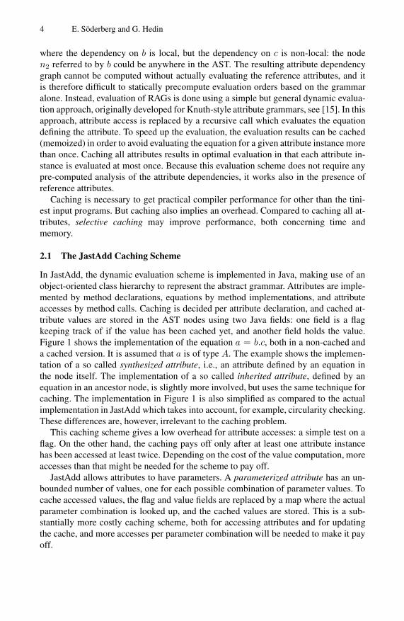
In JastAdd, the dynamic evaluation scheme is implemented in Java, making use of anobject-oriented class hierarchy to represent the abstract grammar. Attributes are imple-mented by method declarations, equations by method implementations, and attributeaccesses by method calls. Caching is decided per attribute declaration, and cached at-tribute values are stored in the AST nodes using two Java fields: one field is a flagkeeping track of if the value has been cached yet, and another field holds the value.Figure 1 shows the implementation of the equation a = b.c, both in a non-cached anda cached version. It is assumed that a is of type A. The example shows the implemen-tation of a so called synthesized attribute, i.e., an attribute defined by an equation inthe node itself. The implementation of a so called inherited attribute, defined by anequation in an ancestor node, is slightly more involved, but uses the same technique forcaching. The implementation in Figure 1 is also simplified as compared to the actualimplementation in JastAdd which takes into account, for example, circularity checking.These differences are, however, irrelevant to the caching problem.
This caching scheme gives a low overhead for attribute accesses: a simple test on aflag. On the other hand, the caching pays off only after at least one attribute instancehas been accessed at least twice. Depending on the cost of the value computation, moreaccesses than that might be needed for the scheme to pay off.
JastAdd allows attributes to have parameters. A parameterized attribute has an un-bounded number of values, one for each possible combination of parameter values. Tocache accessed values, the flag and value fields are replaced by a map where the actualparameter combination is looked up, and the cached values are stored. This is a sub-stantially more costly caching scheme, both for accessing attributes and for updatingthe cache, and more accesses per parameter combination will be needed to make it payoff.
Automated Selective Caching for Reference Attribute Grammars 5
Non-cached version:
class Node {A a() {return b().c();
}}
Cached version:
class Node {boolean a_cached = false;A a_value;A a() {if (! a_cached) {
a_value = b().c();a_cached = true;
}return a_value;
}}
Fig. 1. Caching scheme for non-parameterized attributes
3 Attribute Instance Graphs
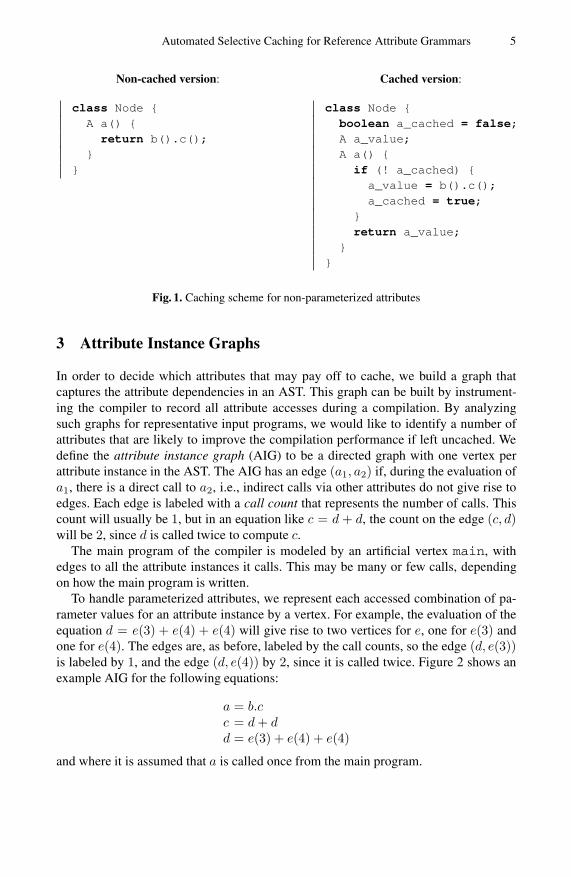
In order to decide which attributes that may pay off to cache, we build a graph thatcaptures the attribute dependencies in an AST. This graph can be built by instrument-ing the compiler to record all attribute accesses during a compilation. By analyzingsuch graphs for representative input programs, we would like to identify a number ofattributes that are likely to improve the compilation performance if left uncached. Wedefine the attribute instance graph (AIG) to be a directed graph with one vertex perattribute instance in the AST. The AIG has an edge (a1, a2) if, during the evaluation ofa1, there is a direct call to a2, i.e., indirect calls via other attributes do not give rise toedges. Each edge is labeled with a call count that represents the number of calls. Thiscount will usually be 1, but in an equation like c = d + d, the count on the edge (c, d)will be 2, since d is called twice to compute c.
The main program of the compiler is modeled by an artificial vertex main, withedges to all the attribute instances it calls. This may be many or few calls, dependingon how the main program is written.
To handle parameterized attributes, we represent each accessed combination of pa-rameter values for an attribute instance by a vertex. For example, the evaluation of theequation d = e(3) + e(4) + e(4) will give rise to two vertices for e, one for e(3) andone for e(4). The edges are, as before, labeled by the call counts, so the edge (d, e(3))is labeled by 1, and the edge (d, e(4)) by 2, since it is called twice. Figure 2 shows anexample AIG for the following equations:
a = b.cc = d + dd = e(3) + e(4) + e(4)
and where it is assumed that a is called once from the main program.

6 E. Söderberg and G. Hedin
main a
b
c d
e(3)
e(4)
1
1
1
21
2
x
LEGEND:
x
instance of attribute x
y when evaluating x, y is called n timesn
Fig. 2. Example AIG
3.1 An Example Grammar
Figure 3 shows parts of a typical JastAdd grammar for name and type analysis. Theabstract grammar rules correspond to a class hierarchy. For example, Use (representinga use of an identifier) is a subclass of Expr. The first attribution rule:
syn Type Expr.type();
declares a synthesized attribute of type Type, declared in Expr and of the name type.All nodes of class Expr and its subclasses will have an instance of this attribute.
abstract Expr;Use : Expr ::= ...;Literal : Expr ::= ...;AddExpr : Expr ::=
e1:Expr e2:Expr;
Decl ::= Type ... ;
abstract Type;Integer : Type;Unknown : Type;
...
syn Type Expr.type();syn Type Decl.type() = ...;
eq Literal.type() =stdTypes().integer();
eq Use.type() = decl().type();eq AddExpr.type() =
(left.type().sameAs(right.type()) ?left.type() : stdTypes.unknown();
syn Decl Use.decl() = lookup(...);inh Decl Use.lookup(String name);inh Type Expr.stdTypes();
syn boolean Type.sameAs(Type t) = ...;...
Fig. 3. Example JastAdd attribute grammar

Automated Selective Caching for Reference Attribute Grammars 7
Decl
A"int a"
Integer
I"int"
Decl
B"int b"
Integer
J"int"
AddExpr
C
"a + b"
Use
D"a" Use
E"b"
AddExpr
F
"a + 5"
Use
G"a"
Literal
H"5"
type
sameAs
type
sameAs
type
type
decl
lookup
type
decl
lookup
type
type
decl
lookup
type
LEGEND:T AST node of type T
Referencea Attribute
Fig. 4. An example attributed AST
Expr.typea1:C D E F G H
Use.decla2:D E G
Decl.typea4:A B
Use.lookupa3:D
"a"E
"b"G
"a"
Type.sameAsa5:IJ
IK
LEGEND:a Attribute
Attribute dependency
I Instance of attribute"p" Parameter value
Fig. 5. Parts of the AIG for the example
Different equations are given for it in the different subclasses of Expr. For example,the equation
eq Use.type() = decl().type();
says that for a Use node, the value of type is defined to be decl().type(). Theattribute decl() is another attribute in the Use node, referring to the appropriate dec-laration node, possibly far away from the Use node in the AST. The decl() attributeis in turn defined using a parameterized attribute lookup, also in the Use node. Thelookup attribute is an inherited attribute, and the equation for it is in an ancestor nodeof the Use node (not shown in the grammar). For more information on name and typeanalysis in RAGs, see [8].
Figure 4 shows parts of an attributed AST for the grammar in Figure 3. The exampleprogram contains two declarations: "int a" and "int b", and two add expressions:"a + b" and "a + 5". For the decl attributes of Use nodes, the reference valuesare shown as arrows pointing to the appropriate Decl node. Similarly, the type at-tributes of Decl nodes have arrows pointing to the appropriate Type node. The nodeshave been labeled A, B, and so on, for future reference.

8 E. Söderberg and G. Hedin
Figure 5 shows parts of the AIG for this example. In the AIG we have groupedtogether all instances of a particular attribute declaration, and labeled each attribute in-stance with the node to which it belongs. For instance, since the node D has the threeattributes (type, decl, and lookup), there are three vertices labeled D in the AIG.For parameterized attribute instances, there is one vertex per actual parameter combi-nation, and their values are shown under the vertex. For instance, the sameAs attributefor I is called with two different parameters: J and K, giving rise to two vertices. (K isa node representing integer literal types and is not shown in Figure 4.) All call countsin the AIG are 1 and have therefore been omitted.
4 Computing a Cache Configuration
Our goal is to automatically compute a good cache configuration for a RAG specifi-cation. A cache configuration is simply the set of attributes configured to be cached.Among the different attribute kinds, there are some that will always be cached, dueto properties of the kind. For example, circular attributes [10], which may depend onthemselves, and non-terminal attributes (NTAs) [29], which may have ASTs as values.There is no cache decision to make for these attributes, i.e., they are unconfigurable.We let PRE denote the set of unconfigurable attributes. Since the attributes in the PRE
set are always cached, we exclude them from remaining definitions in this paper. Welet ALL denote the remaining set of configurable attributes. This ALL set can furtherbe divided into two disjoint sets PARAM and NONPARAM, for parameterized and non-parameterized attributes respectively. For the rest of this paper we will refer to config-urable attributes when we write attributes.
As a basis for our computation, we do profiling runs of the compiler on a set of testprograms, producing the AIG for each program. These runs are done with all attributescached, allowing us to use reasonably large test programs, and making it easy to computethe AIG which reflects the theoretically optimal evaluation with each attribute instanceevaluated at most once. We will refer to these test programs as the profiling input denotedby the set P. Further, a certain profiling input (p ∈ P) will, depending on its structure,require that a certain number of attributes are evaluated. We call this set of attributes theUSEDp set. However, it cannot be assumed that a single profiling input uses all attributes.We define the set of unused attributes for a profiling input p as follows:
UNUSEDp = ALL \ USEDp (1)
4.1 The ONE Set
The calls label on the edges in the AIG reflects the number of attribute calls in a fullycached configuration. To find out if a certain attribute is worth uncaching, we defineextra_evals(ai), i.e., the number of extra evaluations of the attribute instance ai thatwill be done if the attribute a is not cached:
extra_evals(ai) =
{calls(ai)− 1, if a ∈ NONPARAM∑
c∈params(ai)(calls(c)− 1), if a ∈ PARAM
(2)

Automated Selective Caching for Reference Attribute Grammars 9
where params(ai) is the set of vertices in the AIG representing different parametercombinations for the parameterized attribute instance ai. The number of extra evalu-ations is a measure of what is lost by not caching an attribute. The total number ofextra evaluations for an attribute a is simply the sum of the extra evaluations of all itsinstances:
extra_evals(a) =∑
ai∈Icalled(a)
extra_evals(ai); (3)
where Icalled(a) is the set of attribute instances of a that are called at least once. Ofparticular interest is the set of attributes for which all instances are called at most once.These should be good candidates to leave uncached since they do not incur any extraevaluations for a certain profiling input (p). We call this set the ONEp set, and for aprofiling input p it is constructed as follows:
ONEp = {a ∈ USEDp|extra_evals(a) = 0} (4)
The USEDp \ ONEp set contains the remaining attributes in the AIG, i.e., the attributeswhich may gain from being cached, depending on the cost of their evaluation.
4.2 Selecting a Good Profiling Input
To obtain a good cache configuration, it is desirable to use profiling input that is realisticin its attribute usage, and that has a high attribute coverage, i.e., as large a USEDp setas possible. We define the attribute coverage (in percent) for a profiling input, p ∈ P, asfollows:
coverage(p) = (|USEDp|/|ALL|) ∗ 100 (5)
Furthermore, for tools used in an interactive setting with continuous compilation of po-tentially erroneous input, it is important to also take incorrect programs into account.To help fulfill these demands, different profiling inputs can be combined. In particular,a compilation test suite may give high attribute coverage and test both correct and er-roneous programs. But test suites might contain many small programs that do not usethe attributes in a realistic way. In particular, attributes which most likely should be inthe USEDp − ONEp set for an average application may end up in the ONEp sets of thetest suite programs because these are small. By combining the test suite with a largereal program, better results may be obtained. Still, even with many applications and afull test suite, it may be hard to get full coverage. For example, there may be semanticchecks connected to uncommon language constructs and, hence, attributes rarely used.
4.3 Choosing a Cache Configuration
In constructing a good cache configuration we want to consider the USEDp, UNUSEDp,ONEp and ALL sets. From these sets we can experiment with two interesting configura-tions:
ALLONEp = ALL \ ONEp (6)
USEDONEp = USEDp \ ONEp (7)

10 E. Söderberg and G. Hedin
Presumably, the first configuration, which includes the UNUSEDp set, will provide ro-bustness for cases where the profiling input is insufficient, i.e., the USEDp set is toosmall. In contrast, the second configuration may provide better performance in that ituses less memory for cases where the profiling input is sufficient.
4.4 Combining Cache Configurations
In order to combine the results of several profiling inputs, for example, A, B and C inP, we need to consider each of the resulting sets USEDp and ONEp. One attribute mightbe used in the compilation of program A but not in the compilation of program B. If anattribute is used in both B and C, it might belong to ONEB , but not to ONEC , and so on.We want to know which attributes that end up in a total ONEP set for all profiling inputs(p ∈ P), i.e., the attributes that are used by at least one profiling input, but that, if theyare used by a particular profiling input, they are in its ONEp set. More precisely:
ONEP =⋃p∈P
USEDp \⋃p∈P
(USEDp \ ONEp) (8)
These attributes should be good candidates to be left uncached. By including or exclud-ing the UNUSEDP set, we can now construct the following combined cache configura-tion, for a profiling input set P, in analogy to Definition 6 and Definition 7:
ALLONEP = ALL \ ONEP (9)
USEDONEP = USEDP \ ONEP (10)
5 Evaluation
To evaluate our approach we have applied it to the frontend of the Java compiler Jas-tAddJ [9]. This compiler is specified with RAGs using the JastAdd system. We haveprofiled the compilation with one or several Java programs as profiling input, and usedthe resulting AIGs to compute different cache configurations. We have divided our eval-uation into the following experiments:
Experiment A: The effects of no cachingExperiment B: The effects of profiling using a compiler test suiteExperiment C: The effects of profiling using a benchmark applicationExperiment D: The effects of combining B and C
Throughout our experiments we use the results of caching all attributes and the resultsof using a manual configuration, composed by an an expert, for comparison.
5.1 Experimental Setup
All measurements were run on a high-performing computer with two Intel Xeon QuadCore @ 3.2 GHz processors, a bus speed of 1.6 GHz and 32 GB of primary mem-ory. The operating system used was Mac OS X 10.6.2 and the Java version was Java1.6.0._15.
The JastAddJ compiler. The frontend of the JastAddJ compiler (for Java version 1.4 and1.5) has an ALL set containing 740 attributes and a PRE set containing 47 unconfigurable

Automated Selective Caching for Reference Attribute Grammars 11
attributes (14 are circular and 33 are non-terminal attributes). The compiler comes witha configuration MANUAL, with 281 attributes manually selected for caching by the com-piler implementor, an expert on RAGs, making an effort to obtain as good compilationspeed as possible. The compiler performs within a factor of three as compared to thestandard javac compiler, which is good considering that it is generated from a specifica-tion. MANUAL is clearly an expert configuration, and it cannot be expected that a betterone can be obtained manually.
Measuring of performance. The JastAddJ compiler is implemented in Java (generatedfrom the RAG specification), so measuring its compilation speed comes down to mea-suring the speed of a Java program. This is notoriously difficult, due to dynamic classloading, just-in-time compilation and optimization, and automatic memory manage-ment [4]. To eliminate as many of these factors as possible, we use the multi-iterationapproach suggested in [5]. We start by warming up the compiler with a number ofnon-measured compilations (5), thereby allowing class loading and optimization of allrelevant compiler code to take place, in order to reach a steady state. Then we turn offthe just-in-time compilation and run a couple of extra unmeasured compilations (2) todrain any JIT work queues. After that we run several (20) measured compilation runsfor which we compute 95% confidence intervals. In addition to this, we start each mea-sured run with a forced garbage collection (GC) in order to obtain as similar conditionsas possible for each run. Memory usage is measured by checking of available memoryin the Java heap after each forced GC call and after each compilation. The memorymeasurements are also given with a 95% confidence interval. We present a summary ofthese results in Figure 7, Figure 8, Figure 9 and Figure 10. All results have a confidenceinterval of less than ±0.03%. These intervals have not been included in the figuressince they would be barely visible with the resolution we need to use. A complete listof results are available on the web [27].
Profiling and test input. As a basis for profiling input, we use the Jacks test suite [28],the DaCapo benchmark suite [4,26] and a small hello world program. We use 4170 testsfrom the Jacks suite, checking frontend semantics, and the following applications fromthe DaCapo suite (lines of code (LOC)):
ANTLR: an LL(k) parser generator (ca 35 000 LOC).Bloat: a program for optimization and analysis of Java bytecode (ca 41 000 LOC).Chart: a program for plotting of graphs and rendering of PDF files (ca 12 000 LOC).FOP: parses XSL-FO files and generates PDF files (ca 136 000 LOC).HsqlDb: a database application (ca 138 000 LOC).Jython: a Python interpreter (ca 76 000 LOC).Lucene: a program for indexing and searching of large text corpuses (ca 87 000 LOC).PMD: a Java bytecode analyzer for a range of source code problems (ca 55 000 LOC).Xalan: a program for transformation of XML documents into HTML (ca 172 000 LOC).
In our experiments, we use different combinations of these applications and tests asprofiling input. We will denote these profiling input sets as follows:

12 E. Söderberg and G. Hedin
J: The Jacks test suite profiling input setD: The DaCapo benchmarks profiling input set"APP": The benchmark APP of the DaCapo benchmarks.
For example, ANTLR means the ANTLR benchmark.HELLO: The hello world program
We combine these profiling input sets in various ways, for example, the profiling inputset J+ANTLR means we combine the Jacks suite with the benchmark ANTLR. Finally,as test input for performance testing we use the benchmarks from the DaCapo suite andthe hello world program.
Cache configurations. We want to compare the results of using the cache configurationsdefined in Section 4. In addition, the JastAddJ specification comes with a manual cacheconfiguration (MANUAL) which we want to compare to. We also have the option tocache all attributes (ALL), or to cache no attributes (NONE):
MANUAL: This expert configuration is interesting to compare to, as it would be nice ifwe could obtain similar results with our automated methods.
ALL: The ALL configuration is interesting as it is easily obtainable and robust withrespect to performance: there is no risk that a particular attribute will be evaluatedvery many times for a particular input program, and thereby degrade performance.
NONE: The least possible configuration is interesting as it provides a lower bound onthe memory needed during evaluation. However, this configuration will in generalbe useless in practice, leading to compilation times that increase exponentially withprogram size.
From each profiling input set P, we compute USEDP, and ONEP, and construct the con-figurations USEDONEP and ALLONEP (according to Definition 9 and 10):
USEDONEP: This is an interesting cache configuration as it should give good perfor-mance by avoiding caching of unused attributes and attributes used only once byP. The obvious risk with this configuration is that other programs might use at-tributes unused by P, causing performance degradation. There is also a risk thatthe attributes in the ONEP set may belong to another program’s USED \ ONE set,also causing a performance degradation. However, if attributes in ONEP are onlyused once in a typical application, they are likely to be used only once in mostapplications.
ALLONEP: This configuration is more robust than the USEDONEP configuration inthat also unused attributes are cached, which prevents severe performance degrada-tion for those attributes.
Attribute coverage. Figure 6 gives an overview of the USEDP \ ONEP, ONEP andUNUSEDP sets for the profiling inputs from the DaCapo suite. The figure also includesthe combined sets for DaCapo (D) and Jacks (J). Not surprisingly, Hello World has thelowest attribute coverage. Still, it covers as much as 29%. The high coverage is due toanalysis of standard library classes needed to compile the program. The combined re-sults for the DaCapo suite and two of its applications have better or the same coverage

Automated Selective Caching for Reference Attribute Grammars 13
AN
TLR67%
BLO
AT71%
CH
ART
61%
FOP74%
HSQ
LDB81%
JYTH
ON73%
LUC
ENE80%
PMD79%
XA
LAN75%
D84%
J80%
HEL
LO29%
0
200
400
600
Attr
ibut
esAttribute Coverage
USEDP \ ONEP
ONEP
UNUSEDP
Fig. 6. Attribute coverage for the benchmarks in the DaCapo suite, the combined coverage forall the DaCapo applications (D), the combined coverage for the programs in the Jacks suite(J) and for a hello world program. The attribute coverages are given next to the names of theapplication/combination.
as the Jacks suite, i.e., the USEDJ set of Jacks does not enclose the USEDD set of Da-Capo neither does it have an empty UNUSEDJ. These observations are interesting sincethey might indicate that additional tests could be added to Jacks. We can also note thatthe attribute coverage is not directly proportional to the size of an application, as shownby PMD and Lucene which both are smaller than Xalan and FOP in regard to LOC.This may not be surprising since the actual attribute coverage is related to the diversityof language constructs in an application rather than to the application size.
5.2 Experiment A: The Effects of No Caching
To compare the behavior of no caching with various other configurations, we profileda simple Hello World program (HELLO) and then tested performance by compilingthe same program using the configurations ALL, NONE, MANUAL, USEDONEHELLO andALLONEHELLO . The results are shown in Figure 7. It is clear from these results that
Hello World
050
100150200
Compilation Time (% of ALL)
Hello World
0
50
100
Used Memory (% of ALL)
MANUALNONE
USEDONEHELLO
ALLONEHELLO
Fig. 7. Results from Experiment A: Compilation of Hello World using static configurationsalong with configurations obtained using Hello World (HELLO) as profiling input. The averagecompilation time / memory usage when compilating with the ALL configuration were 50.0 ms /14.7 kb. The corresponding values for the NONE configuration were 95.9 ms / 8.4 kb.

14 E. Söderberg and G. Hedin
ANTLR Bloat Chart FOP HsqlDb Jython Lucene PMD Xalan0
20
40
60
80
100
Compilation Time (% of ALL)
ANTLR Bloat Chart FOP HsqlDb Jython Lucene PMD Xalan0
20
40
60
80
100
Used Memory (% of ALL) MANUAL
USEDONEJ
ALLONEJ
Fig. 8. Results from Experiment B: Compilation of DaCapo benchmarks using configurationsfrom the Jacks suite. All results are given in relation to the compilation time and memory usageof the ALL configuration and results for MANUAL are included for comparison.
the minimal NONE configuration is not a good configuration, not even on this smalltest program. Even though it provides excellent memory usage, the compilation time ismore than twice as slow as any of the other configurations. For a larger application theNONE configuration would be useless.
5.3 Experiment B: The Effects of Profiling Using a Compiler Test Suite
To show the effects of using a compiler test suite we profiled the compilation of theJacks suite and obtained the two configurations USEDONEJ and ALLONEJ. We thenmeasured performance when compiling the DaCapo benchmarks using these configu-rations. The results are shown in Figure 8 and are given as percent in relation to the com-pilation time and memory usage of the ALL configuration1. The results for the MANUAL
configuration are included for comparison.Clearly, the MANUAL configuration performs better with regard to both compilation
time and memory usage, with an average compilation time / memory usage of 75% /47% in relation to the ALL configuration. The average results for USEDONEJ is 83% /67%. The ALLONEJ configuration has the same average compilation time 83% / 72%,but higher average memory usage. It is interesting to note that USEDONEJ is robustenough to handle the compilation of all the DaCapo benchmarks. So it seems that the
1 The absolute average results for ALL are the following: Antlr (1.462s/0.270Gb),Bloat (1.995s/0.339Gb), Chart (0.928s/0.177Gb), FOP (8.328s/1.362Gb), HsqlDb(6.054s/1.160Gb), Jython (3.257s/0.611Gb), Lucene (4.893s/0.930Gb), PMD(3.921s/0.691Gb), Xalan (6.606s/1.141Gb).

Automated Selective Caching for Reference Attribute Grammars 15
Jacks test suite has a sufficiently large coverage, i.e., we can use the USEDONEJ con-figuration rather than the ALLONEJ configuration. In doing so, we can use less memorywith the same performance and robustness.
5.4 Experiment C: The Effects of Profiling Using a Benchmark Program
To show the effects of using benchmarks we profiled using each of the DaCapo bench-marks obtaining the USEDONE and ALLONE configurations for each benchmark. Wealso combined the profiling results for all the benchmarks to create the combined con-figurations USEDONED and ALLONED. We then measured performance when compil-ing the DaCapo benchmarks using these configurations. A selected set of the resultsare shown in Figure 9, including the combined results and the best USEDONE andALLONE configurations from the individual benchmarks. All results are given as per-cent in relation to the compilation time and memory usage of the ALL configuration.The results for the MANUAL set are also included for comparison. Note that not all re-sults are shown in Figure 9. Two of the excluded configurations USEDONEANTLR andUSEDONECHART performed worse than full caching (ALL). These results validate theconcern that the USEDONEp configuration would have robustness problems for insuffi-cient profiling input. In this case, neither ANTLR nor Chart were sufficient as profiling
ANTLR Bloat Chart FOP HsqlDb Jython Lucene PMD Xalan0
20
40
60
80
100
Compilation Time (% of ALL)
ANTLR Bloat Chart FOP HsqlDb Jython Lucene PMD Xalan0
20
40
60
80
100
Used Memory (% of ALL)
MANUAL
USEDONED
ALLONED
USEDONEBLOAT
ALLONEANTLR
Fig. 9. Results from Experiment C: Compilation of DaCapo benchmarks using configurationsfrom the DaCapo benchmarks. All results are shown as compilation time and memory usageas percent of the results for the ALL configuration and results for MANUAL are included forcomparison.

16 E. Söderberg and G. Hedin
inputs on their own. We can note that these two applications have the least coverageamong the applications from the DaCapo suite (67% for ANTLR and 61% for Chart).
The USEDONE configurations. The USEDONE configurations for ANTLR and Chartperform worse than the ALL configuration for several of the applications in the DaCapobenchmarks: FOP, Lucene and PMD. The remaining USEDONE configurations can besorted with regard to percent of compilation time, calculated as the geometric mean ofthe DaCapo benchmark program compilation times (each in relation to the ALL config-uration), as follows:
80%: USEDONEBLOAT (mem. 62%)82%: USEDONEFOP (mem. 63%), USEDONEXALAN (mem.66%)83%: USEDONEHSQLDB (mem. 68%), USEDONEJYTHON (mem. 65%),
USEDONELUCENE (mem. 68%), USEDONEPMD (mem. 66%)84%: USEDONED (mem. 70%)
These results indicate that a certain coverage is needed in order to obtain a robustUSEDONE configuration. It is also interesting to note that the combined USEDONED
configuration for DaCapo performs the worst (except for the non-robust configurations).One possible explanation to this performance might be that some attributes ending upin the USEDONED set might be used rarely or not at all in several compilations. Still,these attributes are cached which leads to more memory usage.
The ALLONE configurations. The ALLONE configurations generally perform worsethan the USEDONE configurations. This result might be due to the fact that these config-urations include unused attributes for robustness. However, this strategy for robustnesspays off in that all ALLONE configurations become robust, i.e., they compile all theDaCapo benchmarks faster than the ALL configuration. The ALLONE configurationscan be sorted as follows, with regard to percent of compilation time:
80%: ALLONEANTLR (mem. 69%)82%: ALLONEBLOAT (mem. 69%), ALLONEFOP (mem. 69%)83%: ALLONECHART (mem. 71%)84%: ALLONEHSQLDB (mem. 73%), ALLONEJYTHON (mem. 70%),
ALLONEXALAN (mem. 70%)85%: ALLONELUCENE (mem. 73%), ALLONEPMD (mem. 71%)86%: ALLONED (mem. 73%)
These results indicate that a profiled application does not necessarily need to be large,or have the best coverage, for the resulting configuration to provide good performance.The best individual ALLONE configuration is obtained from profiling ANTLR whichis remarkable since ANTLR has the next lowest attribute coverage, while the combinedALLONED configuration for DaCapo performs the worst on average. This result mightbe due to the fact that the combined configuration caches attributes that might be inthe ONE set of an individual application. This fact is also true for several of the indi-vidual configurations but apparently the complete combination takes the edge off theconfiguration.

Automated Selective Caching for Reference Attribute Grammars 17
5.5 Experiment D: The Effects of Combining B and C
To show the effects of profiling using a compiler test suite (B) together with profil-ing a benchmark program (C) we combine the cache configurations from experimentB and C. We then measured performance when compiling the DaCapo benchmarksusing these configurations. A selected set of the results are shown in Figure 10, in-cluding the fully combined results and the best USEDONE and ALLONE configura-tions, obtained from combining configurations from ANTLR and Jacks. We can sortthe USEDONE configurations, with regard to their percent of compilation time, asfollows:
81%: USEDONEJ+ANTLR (mem. 64%), USEDONEJ+BLOAT (mem. 67%),USEDONEJ+CHART (mem. 65%)
82%: USEDONEJ+FOP (mem. 68%), USEDONEJ+XALAN (mem. 69%)83%: USEDONEJ+JYTHON (mem. 69%)84%: USEDONEJ+HSQLDB (mem. 70%),
USEDONEJ+LUCENE (mem. 70%), USEDONEJ+PMD (mem. 70%)85%: USEDONEJ+D (mem. 71%)
ANTLR Bloat Chart FOP HsqlDb Jython Lucene PMD Xalan0
20
40
60
80
100
Compilation Time (% of ALL)
ANTLR Bloat Chart FOP HsqlDb Jython Lucene PMD Xalan0
20
40
60
80
100
Used Memory (% of ALL)
MANUAL
USEDONEJ+D
ALLONEJ+D
USEDONEJ+ANTLR
ALLONEJ+ANTLR
Fig. 10. Results from Experiment D: Compilation of DaCapo benchmarks using combined con-figurations from the Jacks and DaCapo suites. All results are shown as compilation time andmemory usage as percent of the results for the ALL configuration and results for MANUAL areincluded for comparison.

18 E. Söderberg and G. Hedin
We can sort the ALLONE configurations in the same fashion:
82%: ALLONEJ+ANTLR (mem. 66%), ALLONEJ+BLOAT (mem. 68%)84%: ALLONEJ+CHART (mem. 66%)85%: ALLONEJ+D (mem. 72%)88%: ALLONEJ+FOP (mem. 69%), ALLONEJ+JYTHON (mem. 69%),
ALLONEJ+XALAN (mem. 70%)89%: ALLONEJ+LUCENE (mem. 71%), ALLONEJ+PMD (mem. 71%)
We note that the influence of the benchmarks improve the average performance of theJacks configurations (83%) with one or two percent. It is interesting to note that thebenchmarks providing the best performance on average for Jacks, independent of con-figuration, are those with small coverage and few lines of code. These results indicatethat it is worth combining a compiler test suite with a normal program, but that theprogram should not be too large or complicated. This way, we will end up with a con-figuration that caches attributes that end up in the USEDONE set of any small intricateprogram, as well as in the USEDONE set of larger programs, but without caching at-tributes that seem to be less commonly used many times. Further, it should be noted thatthe memory usage results for the combined ALLONEJ+D and USEDONEJ+D presentunexpected results when compiling Jython. Presumably, the first configuration shoulduse more memory than the second configuration, but the results show the reverse. Thedifference is slight but still statistically significant. At this point we have no explanationfor this unexpected result.
6 Related Work
There has been a substantial amount of research on optimizing the performance ofattribute evaluators and to avoid storing all attribute instances in the AST. Much ofthis effort is directed towards optimizing static visit-oriented evaluators, where attributeevaluation sequences are computed statically from the dependencies in an attributegrammar. For RAGs, such static analysis is, in general, not possible due to the refer-ence attributes. As an example, Saarinen introduces the notion of temporary attributesthat are not needed outside a single visit, and shows how these can be stored on a stackrather than in the AST [23]. The attributes we have classified as ONE correspond to suchtemporary attributes: they are accessed only once, and can be seen as stored in the stackof recursive attribute calls. Other static analyses of attribute grammars are aimed at de-tecting attribute lifetimes, i.e., the time between the computation of an attribute instanceuntil its last use. Attributes whose instances have non-overlapping lifetimes can sharea global variable, see, e.g., [17]. Again, such analysis cannot be directly transfered toRAGs due to the use of reference attributes.
Memoization is a technique for storing function results for future use, and is used,for example, in dynamic programming [3]. Our use of cached attributes is a kind ofmemoization. Acar et al. present a framework for selective memoization in a function-oriented language [1]. However, their approach is in a different direction than ours,intended to help the programmer to use memoized functions more easily and with morecontrol, rather than to find out which functions to cache. There are also other differences

Automated Selective Caching for Reference Attribute Grammars 19
between memoization in function-oriented programming, and in our object-orientedevaluator. In function-oriented programming, the functions will often have many andcomplex arguments that can be difficult or costly to compare, introducing substantialoverhead for memoization. In contrast, our implementation is object-oriented, reducingmost attribute calls to parameterless functions which are cheap to cache. And for pa-rameterized attributes, the arguments are often references which are cheap to compare.
7 Conclusions and Future Work
We have presented a profiling technique for automatically finding a good cachingconfiguration for compilers generated from RAG specifications. Since the attribute de-pendencies in RAGs cannot be computed statically, but depend on the evaluation of ref-erence attributes, we have based the technique on profiling of test programs. We haveintroduced the notion of an attribute dependency graph with call counts, extracted froman actual compilation. Experimental evaluation on a generated Java compiler showsthat by profiling on only a single program with an attribute coverage of only 67%, wereach a mean compilation speed-up of 20% and an average decrease in memory usageof 38%, as compared to caching all configurable attributes. This is close to the averagecompilation speed-up obtained for a manually composed expert configuration (25%).The corresponding average decrease in memory usage for the manual configuration(53%) is still significantly better. Our evaluation shows that we get similar performanceimprovements for both tested cache configuration approaches. Given these results, wewould recommend the ALLONE configuration due to its higher robustness.
We find these results very encouraging and intend to continue this work with moreexperimental evaluations. In particular, we would like to study the effects of caching,or not caching, parameterized attributes, and to apply the technique to compilers forother languages. Further, we would like to study the effects of analyzing the contentof the attribute equations. Most likely there are attributes which only return a constantor similar and, hence, should not benefit from caching independent of the number ofcalls. Finally, it would be interesting to further study the differences between the cacheconfigurations from the profiler and the manual configuration.
Acknowledgements
We are grateful to Torbjörn Ekman for fruitful discussions and for implementing sup-port in JastAdd for profiling and separate cache configurations. Thanks also to anony-mous reviewers for comments on an earlier version of this paper.
References
1. Acar, U.A., Blelloch, G.E., Harper, R.: Selective memoization. In: POPL, pp. 14–25. ACM,New York (2003)
2. Åkesson, J., Ekman, T., Hedin, G.: Implementation of a Modelica compiler using JastAddattribute grammars. Science of Computer Programming 75(1-2), 21–38 (2010)

20 E. Söderberg and G. Hedin
3. Bellman, R.: Dynamic Programming. Princeton University Press, Princeton (1957)4. Blackburn, S.M., Garner, R., Hoffmann, C., Khang, A.M., McKinley, K.S., Bentzur, R.,
Diwan, A., Feinberg, D., Frampton, D., Guyer, S.Z., Hirzel, M., Hosking, A., Jump, M., Lee,H., Moss, J.E.B., Moss, B., Phansalkar, A., Stefanovic, D., VanDrunen, T., von Dincklage,D., Wiedermann, B.: The DaCapo benchmarks: java benchmarking development and anal-ysis. In: OOPSLA 2006: Proceedings of the 21st Annual ACM SIGPLAN Conference onObject-Oriented Programming Systems, Languages, and Applications, pp. 169–190. ACM,New York (2006)
5. Blackburn, S.M., McKinley, K.S., Garner, R., Hoffmann, C., Khan, A.M., Bentzur, R.,Diwan, A., Feinberg, D., Frampton, D., Guyer, S.Z., Hirzel, M., Hosking, A.L., Jump, M.,Lee, H., Moss, J.E.B., Phansalkar, A., Stefanovic, D., VanDrunen, T., von Dincklage, D.,Wiedermann, B.: Wake up and smell the coffee: evaluation methodology for the 21st cen-tury. Communications of the ACM 51(8), 83–89 (2008)
6. Boyland, J.T.: Remote attribute grammars. Journal of the ACM 52(4), 627–687 (2005)7. Bürger, C., Karol, S., Wende, C.: Applying attribute grammars for metamodel semantics. In:
Proceedings of the International Workshop on Formalization of Modeling Languages. ACMDigital Library (2010)
8. Ekman, T., Hedin, G.: Modular Name Analysis for Java Using JastAdd. In: Lämmel,R., Saraiva, J., Visser, J. (eds.) GTTSE 2005. LNCS, vol. 4143, pp. 422–436. Springer,Heidelberg (2006)
9. Ekman, T., Hedin, G.: The Jastadd Extensible Java Compiler. In: 22nd Annual ACM SIG-PLAN Conference on Object-Oriented Programming, Systems, Languages, and Applications(OOPSLA 2007), pp. 1–18. ACM, New York (2007)
10. Farrow, R.: Automatic generation of fixed-point-finding evaluators for circular, but well-defined, attribute grammars. In: SIGPLAN 1986: Proceedings of the 1986 SIGPLAN Sym-posium on Compiler Construction, pp. 85–98. ACM, New York (1986)
11. Hedin, G.: Reference Attributed Grammars. Informatica (Slovenia) 24(3), 301–317 (2000)12. Hedin, G., Magnusson, E.: JastAdd: an aspect-oriented compiler construction system. Sci-
ence of Computer Programming 47(1), 37–58 (2003)13. Huang, S.S., Hormati, A., Bacon, D.F., Rabbah, R.M.: Liquid metal: Object-oriented pro-
gramming across the hardware/Software boundary. In: Ryan, M. (ed.) ECOOP 2008. LNCS,vol. 5142, pp. 76–103. Springer, Heidelberg (2008)
14. Ibrahim, A., Jiao, Y., Tilevich, E., Cook, W.R.: Remote batch invocation for compositionalobject services. In: Drossopoulou, S. (ed.) ECOOP 2009. LNCS, vol. 5653, pp. 595–617.Springer, Heidelberg (2009)
15. Jourdan, M.: An optimal-time recursive evaluator for attribute grammars. In: Paul, M., Robi-net, B. (eds.) Programming 1984. LNCS, vol. 167, pp. 167–178. Springer, Heidelberg (1984)
16. Jouve, W., Palix, N., Consel, C., Kadionik, P.: A SIP-based programming framework for ad-vanced telephony applications. In: Schulzrinne, H., State, R., Niccolini, S. (eds.) IPTComm2008. LNCS, vol. 5310, pp. 1–20. Springer, Heidelberg (2008)
17. Kastens, U.: Lifetime analysis for attributes. Acta Informatica 24(6), 633–651 (1987)18. Kats, L.C.L., Sloane, A.M., Visser, E.: Decorated Attribute Grammars: Attribute Evaluation
Meets Strategic Programming. In: de Moor, O., Schwartzbach, M.I. (eds.) CC 2009. LNCS,vol. 5501, pp. 142–157. Springer, Heidelberg (2009)
19. Knuth, D.E.: Semantics of Context-free Languages. Mathematical Systems Theory 2(2),127–145 (1968); Correction: Mathematical Systems Theory 5(1), 95–96 (1971)
20. Nilsson-Nyman, E., Ekman, T., Hedin, G., Magnusson, E.: Declarative intraprocedural flowanalysis of Java source code. In: Proceedings of the Eight Workshop on Language Descrip-tion, Tools and Applications (LDTA 2008). Electronic Notes in Theoretical Computer Sci-ence, Elsevier B.V., Amsterdam (2008)

Automated Selective Caching for Reference Attribute Grammars 21
21. Poetzsch-Heffter, A.: Prototyping realistic programming languages based on formal specifi-cations. Acta Informatica 34(10), 737–772 (1997)
22. Rajan, H.: Ptolemy: A language with quantified, typed events (2010),http://www.cs.iastate.edu/~ptolemy/
23. Saarinen, M.: On constructing efficient evaluators for attribute grammars. In: Ausiello, G.,Böhm, C. (eds.) ICALP 1978. LNCS, vol. 62, pp. 382–397. Springer, Heidelberg (1978)
24. Schäfer, M., Ekman, T., de Moor, O.: Sound and Extensible Renaming for Java. In: Kicza-les, G. (ed.) 23rd Annual ACM SIGPLAN Conference on Object-Oriented Programming,Systems, Languages, and Applications (OOPSLA 2008). ACM Press, New York (2008)
25. Sloane, A.M., Kats, L.C.L., Visser, E.: A Pure Object-Oriented Embedding of AttributeGrammars. In: Proceedings of the 9th Workshop on Language Descriptions, Tools and Ap-plications, LDTA 2009 (2009)
26. The DaCapo Project. The DaCapo Benchmarks (2009), http://dacapobench.org27. The JastAdd Caching Trac. Performance results for JastAddJ (2010),
http://svn.cs.lth.se/trac/jastadd-caching28. The Mauve Project. Jacks (Jacks is an Automated Compiler Killing Suite) (2009),
http://sources.redhat.com/mauve29. Vogt, H., Doaitse Swierstra, S., Kuiper, M.F.: Higher-order attribute grammars. In: PLDI, pp.
131–145 (1989)30. Van Wyk, E., Bodin, D., Gao, J., Krishnan, L.: Silver: An extensible attribute grammar sys-
tem. Science of Computer Programming 75(1-2), 39–54 (2010)31. Van Wyk, E., Krishnan, L., Bodin, D., Schwerdfeger, A.: Attribute grammar-based language
extensions for java. In: Bateni, M. (ed.) ECOOP 2007. LNCS, vol. 4609, pp. 575–599.Springer, Heidelberg (2007)

Reference Attribute Grammars for MetamodelSemantics
Christoff Burger, Sven Karol, Christian Wende, and Uwe Aßmann
Institut fur Software- und MultimediatechnikTechnische Universitat Dresden
Dresden, Germany{christoff.buerger,sven.karol,c.wende,uwe.assmann}@tu-dresden.de
Abstract. While current metamodelling languages are well-suited for the struc-tural definition of abstract syntax and metamodelling platforms like the EclipseModelling Framework (EMF) provide various means for the specification of atextual or graphical concrete syntax, techniques for the specification of model se-mantics are not as matured. Therefore, we propose the application of referenceattribute grammars (RAGs) to alleviate the lack of support for formal seman-tics specification in metamodelling. We contribute the conceptual foundations tointegrate metamodelling languages and RAGs, and present JastEMF — a toolfor the specification of EMF metamodel semantics using JastAdd RAGs. Thepresented approach is exemplified by an integrated metamodelling example. Itsadvantages, disadvantages and limitations are discussed and related to metamod-elling, attribute grammars (AGs) and other approaches for metamodel semantics.
1 Introduction
Metamodelling is a vital activity for Model-Driven Software Development (MDSD).It covers the definition of structures to represent abstract syntax models, the specifica-tion of a concrete syntax, and the specification of the meaning of models [1]. Whileinfrastructures like the Eclipse Modelling Framework (EMF) [2] provide means for thespecification of abstract syntax and various associated tools for the specification of atextual or graphical concrete syntax, techniques for the specification of model seman-tics are not as matured [1].
In this paper we propose the application of RAGs [3] — a well-investigated exten-sion of Knuth’s classic AGs [4] — to alleviate the lack of support for formal semanticsspecification in metamodelling. They enable (1) the specification of semantics on treeand graph-based abstract syntax structures with unique spanning trees, (2) complete-ness and consistency checks of semantic specifications, and (3) the generation of animplementation of semantics specifications.
The contributions of this paper are as follows: The next section discusses commonconcerns in the specification of metamodels, identifies key capabilities we target withsemantics-integrated metamodelling and introduces a motivating example. In Section 3we sketch general foundations for the application of RAGs for metamodel semantics— our semantics-integrated metamodelling approach. In Section 4 we demonstrate the
B. Malloy, S. Staab, and M. van den Brand (Eds.): SLE 2010, LNCS 6563, pp. 22–41, 2011.c© Springer-Verlag Berlin Heidelberg 2011

Reference Attribute Grammars for Metamodel Semantics 23
Fig. 1. Transformations in Metamodelling
feasibility of this idea by presenting JastEMF, a tool that integrates the Ecore meta-modelling language and the JastAdd [5] attribute grammar system. In Section 5 wedescribe the application of our semantics-integrated metamodelling approach to im-plement the SiPLE-Statemachines language introduced in Section 2. In Section 6 weevaluate JastEMF against the key capabilities identified for semantics-integrated meta-modelling based on our experiences with the SiPLE-Statemachines case study. Finally,we discuss related work in Section 7 and conclude our contribution in Section 8.
2 Motivation for Semantics-Integrated Metamodelling
This section motivates our idea of semantics-integrating metamodelling with RAGs byidentifying methodical gaps to achieve common objectives in metamodelling. After-wards, we introduce a set of key capabilities we target with semantics-integrated meta-modelling and introduce SiPLE-Statemachines, an exemplary metamodel project thatserves as a continuous example throughout this paper.
2.1 Metamodelling: Objectives, Transformations, Specifications
Metamodelling has the objective to specify the implementation of a modellinglanguage. Such implementation should provide means to transform programs (i.e., mod-els) starting from (1) their textual representation to (2) their abstract syntax represen-tation and finally (3) representations of their static and execution semantics [1]. In themetamodelling world, all these representations and transformations are related to thelanguage’s metamodel, which typically declares the data structures that are used forrepresenting language constructs in abstract syntax models and is the interface for thespecification of concrete syntax and semantics. As depicted in Figure 1, each trans-formation’s input and output model is built using specific kinds of constructs of thelanguage metamodel. A first transformation — typically specified using regular ex-pressions and context-free grammars — derives an abstract syntax tree (AST) fromtextual symbols. The data structure required to represent the AST is solely declaredby the Metaclasses, Attributes and Containment References in themetamodel. In a second transformation, the structures that are declared as Non-Con-tainment References (e.g., connecting variable usage with variable declarations)

24 C. Burger et al.
need to be derived, resulting in a reference-attributed model — i.e., the abstract syntaxtree with a superimposed reference graph. Graphical editors often directly operate onsuch reference-attributed models (cf. Figure 1) and rely on a direct manipulation ofnon-containment references. A last transformation performs semantics evaluations toderive values for Derived Attributes and executes Operations declared inthe metamodel. Note that the reference-attributed model and the full-attributed modelstill contain the abstract syntax tree as their spanning tree.
All the above mentioned transformations are important artefacts of a language and,thus, motivate a formal definition. However, formal approaches for the specification ofstatic or execution semantics are not yet established in the metamodelling world. Asdepicted in Figure 1 we aim at closing this gap by the application of RAGs for thespecification of metamodel semantics.
2.2 Capabilities of Semantics-Integrated Metamodelling
By applying RAGs to achieve semantics-integrated metamodelling we expect to com-bine the benefits of metamodelling frameworks and attribute grammars. However, toour experience, integration means not only combination of benefits but often also acompromise of the technical and methodical capabilities of the individual approaches.We therefore collected a number of technical key capabilities to be contributed by eachindividual approach that afterwards will be used to evaluate our integrated solution.
Metamodelling frameworks (e.g., the EMF) are built around a metamodelling lan-guage (e.g., Ecore) and typically provide tools for the specification and implementationof modelling languages and their tooling. In particular they provide:
MM 1: Metamodelling Abstraction: Metamodelling language that provides a dedi-cated abstraction to specify language metamodels.
MM 2: Metamodelling Consistency: Tools to check the structural completeness andconsistency of metamodel specifications.
MM 3: Metamodel Implementation Generators: Generators to derive implementa-tions from metamodel specifications.
MM 4: Metamodel/Model Compatibility: A common repository and representationthat enables integration of modelling languages and models.
MM 5: Tooling Compatibility: Common platform for tool integration/application:
MM 5.1: Model-to-Model Transformation Tools: E.g., ATL [6] or XTend [7].MM 5.2: Model-to-Text Transformation Tools: Code generators and model-dri-
ven template languages like Mofscript [8] or XPand [7].MM 5.3: Text-to-Model Transformation Tools: Parser generators for models as
EMFText [9], Monticore [10] or XText [11].MM 5.4: Generic Model Editors: Generic tools to access and edit models as the
Generic EMF editor [2] or Exeed [12].MM 5.5: Tooling Generators: Tooling to specify and generate textual (EMFText,
Monticore, XText) or graphical (GMF [2], EuGENia1) model editors.
1 http://www.eclipse.org/gmt/epsilon/doc/articles/eugenia-gmf-tutorial/

Reference Attribute Grammars for Metamodel Semantics 25
Attribute grammar systems typically provide means for the specification of lan-guages’ abstract syntax and semantics and tools to derive an implementation from suchspecifications. In particular they provide:
AG 1: Semantics Abstraction: Well-investigated, declarative abstraction for formalsemantics specifications.
AG 2: Semantics Consistency: Tooling to check the structural completeness and con-sistency of semantics specifications.
AG 3: Semantics Generators: Generators to derive an implementation (i.e., evalua-tor) from semantics specifications.
AG 4: Semantics Modularity: Modular, extensible semantics specifications [13].
2.3 SiPLE-Statemachines: A Typical Modelling Language
To exemplify and evaluate semantics-integrated metamodelling we will use a typi-cal modelling scenario. It is built upon a Simple imperative Programming LanguageExample (SiPLE) and a statemachine language which are combined to support the mod-elling of executable statemachines.
SiPLE’s main features are boolean, integer, and real arithmetics, nested scopes, nestedprocedure declarations, recursion, while loops and conditionals. All these features ofSiPLE have the intuitive semantics familiar from imperative programming languages.Listing 1.1 shows a basic SiPLE program that asks the user for a number, computes itsFibonacci value and prints it.
Listing 1.1. Fibonacci Numbers in SiPLE
Procedure main ( ) BeginProcedure f i b o n a c c i ( Var n : I n t e g e r ) : I n t e g e r Begin
I f n = 0 Or n = 1 Then Return 1 ; Fi ;Return f i b o n a c c i ( n−2) + f i b o n a c c i ( n−1);
End ;
Var n : I n t e g e r ;Read n ;Write f i b o n a c c i ( n ) ;
End ;
Statemachines describe the behaviour of systems using a state-based abstraction [14].In contrast to the textual syntax of SiPLE, they are typically modelled using a graphi-cal notation. The exemplary statemachine depicted in Fig. 2 describes the behaviour ofa phone. It uses concepts like states (e.g., Dialing), transitions (e.g., incomingcall), guard conditions and actions. With transitions the phone reacts on particu-lar events from the environment by changing states, e.g., incoming call wherethe phone changes from Waiting to Ringing. Guards and actions enable a morefine-grained specification of boolean conditions and imperative behaviour, respectively.Therefore, we want to combine the statemachine language and SiPLE to SiPLE-State-machine. Consider for instance the state Dialing where an entry action is used toread a number from the user (Read number;). SiPLE action statements and booleanguard expressions can also be associated to transitions. For instance, when the phone is

26 C. Burger et al.
Fig. 2. Phone example modelled in a generated GMF editor for SiPLE-Statemachine
in the Dialing state and receives a call event, it checks the entered number usinga boolean SiPLE expression and changes its state in accordance. While walking the ac-cording transition it writes the dialed or rejected number to the standard output (Writenumber; Write true; or Write number; Write false;).
In this paper we will demonstrate and evaluate the integration of metamodelling andRAGs by implementing SiPLE-Statemachines. Relying on the key capabilities identi-fied in Section 2.2 we plan to provide:
– A metamodel (MM 1, MM 2, MM 3), textual concrete syntax (MM 5.3, MM 5.5)and attribute-grammar semantics (AG 1, AG 2, AG 3) for SiPLE.
– An interpreter that implements an execution semantics for SiPLE (MM 5).– The SiPLE-Statemachine metamodel (MM 1, MM 2, MM 3) composed from the
two metamodels of SiPLE and Statemachine (MM 4).– A generated graphical editor for SiPLE-Statemachine (MM 5.5).– An attribute-grammar semantics for SiPLE-Statemachine (AG 1, AG 2, AG 3, AG
4), e.g., for mapping transition labels to states and to reason about state reachability.– An execution semantics for SiPLE-Statemachine by implementing a model-to-text
transformation (MM 5.2) for statemachines to plain SiPLE code.
3 Foundations of Attribute Grammars for Metamodel Semantics
Because RAGs rely on a specific representation of abstract syntax, their application inmetamodelling requires an integration with metamodel constructs. In this section weprepare such integration by investigating RAGs’ specific syntax requirements, clarify-ing what kind of semantics they can specify and which kind of model information thesesemantics represent, and finally showing that most metamodelling languages indeedsatisfy RAGs’ syntax requirements.
3.1 Reference Attribute Grammars and Metamodel Semantics
RAGs are used to specify semantics for tree structures that are usually specified us-ing a context-free grammar (CFG). Given a tree the RAG annotates it with values and

Reference Attribute Grammars for Metamodel Semantics 27
imposes a graph on it representing the language’s semantics. Because we like to useRAGs for metamodel semantics, we must identify metamodel constructs that inducesuch tree-structure in model instances. We like to use our approach not only for certainmetamodels, but rather for any metamodel developed in a metamodelling language.Thus, the separation of metamodel constructs into tree- and graph-inducing structures— into syntax and semantics — should be metamodelling language inherent, i.e. beimplied by the meta-metamodel2. For this purpose, we investigate common metamod-elling languages’ concepts and distinguish them into syntactic (tree structure defining)and semantic (graph structure declaring) ones. Both sets will be disjunct. Given thisseparation RAGs are indeed appropriate to specify metamodel semantics in the sensethat they can be used to specify the transformation of abstract syntax trees to refer-ence attributed graphs and full-attributed graphs (cf. Figure 1). RAGs can be used forany kind of static model semantics like model checking and analysis. Definition 3.1summarises the foundations of integrating RAGs and metamodels:
Definition 3.1 (Metamodel Semantics): Let Ω be a metamodel and EΩ the finite set ofits elements. Let EsynΩ and EsemΩ be disjunct subsets of EΩ , whereas EΩ = EsynΩ ∪EsemΩ . Let Eω be the set of entities of a model instance ω ∈ Ω. Since ω ∈ Ω, allentities e ∈ Eω have a type te ∈ EΩ . Let SΩ be a function that defines for all ω ∈ Ω foreach entity e ∈ Eω with te ∈ EsemΩ the value of e. We call SΩ a metamodel semanticfor Ω. Iff EsynΩ specifies a spanning tree for each ω ∈ Ω, SΩ can be specified with aRAG.
The metamodel semantics SΩ can depend on any metamodel element me ∈ EΩ . Theyeven can depend on themselves, in which case they are only well-defined if there existsa fix-point. Thus, different model instances can only have different semantics, if the se-mantics depend on syntactic elements me ∈ EsynΩ . Colloquially explained, a model’ssemantics (i.e., all entities {e|e ∈ Eω ∧ te ∈ EsemΩ}) depend on its structure (i.e., allentities {e|e ∈ Eω ∧ te ∈ EsynΩ
}).What remains to show is, which metamodelling concepts belong to EsynΩ
and EsemΩ
and that indeed EsynΩspecifies a tree structure.
3.2 Common Metamodelling Languages and Abstract Syntax Trees
Most metamodelling languages support (1) metaclasses consisting of (2) non-derivedand (3) derived attributes and (4) operations. Metaclasses can be related to each otherby (5) containment and (6) non-containment relationships. Non-derived attribute val-ues represent AST terminals in models and, thus, are in EsynΩ . Containment refer-ences model that instances of a metaclass C1 consist of instances of a metaclass C2.The contained C2 instances are an inextricable, structural part of the C1 instances.The relationship between C1 and C2 is a composite and iff an instance e2 ∈ C2 isa composite of an instance e1 ∈ C1, e1 cannot be a composite of e2. Thus, contain-ment relationships specify tree structures. They are in EsynΩ . Derived attributes andside-effect free operations model the values that can be calculated from other valuesof a given model. Non-containment relationships model arbitrary references between
2 Most metamodelling languages are specified in themselves, such that it is appropriate just totalk about metamodels in the following.

28 C. Burger et al.
metaclasses. Thus, derived attributes, side-effect free operations, and non-containmentrelationships are in EsemΩ . Operations with side-effects can model either, extensions ofmodels derived from existing model information or arbitrary model manipulations. De-rived model extensions are in EsemΩ , because they can be considered to be part of thegraph imposed by semantics (w.r.t. AGs such derived model extensions are higher-orderattributes [15]). Operations that represent arbitrary model manipulations (e.g., to deletemodel elements or imperatively add new elements) cannot be handled by our definitionof metamodel semantics.
3.3 Graphs and (Partial) Reference-Attributed Models
In the domain of modelling, often reference-attributed models (cf. Section 2.1 and Fig. 1)are the starting point for semantic evaluations. A typical scenario are models developedin graphical editors. Of course, it is no problem for a RAG-based metamodel semanticSΩ if elements of EsemΩ of a model instance have a predefined value — i.e., if insteadof a tree the semantic evaluation starts from a graph with a unique spanning tree.
Throughout semantic evaluation, a RAG evaluator can use such predefined valuesand simply ignore their specified semantics. If all occurrences of a non-containmentreference, for every possible model instance, have a predefined value, the specificationof its semantics can even be omitted. Thus, (partial) reference-attributed models do notinfluence the applicability of our RAG approach for metamodel semantics.
4 JastEMF: An Exemplary Attribute Grammar andMetamodelling Language Integration
In this section, we discuss the integration of an exemplary metamodelling framework(EMF [2]) and RAG system (JastAdd [5]). We shortly introduce both approaches andthen discuss the details of their integration in JastEMF.
4.1 The Eclipse Modelling Framework
The EMF is a common metamodelling infrastructure for the Eclipse platform providingmetamodel development and implementation tools based on the metamodelling lan-guage Ecore [2]. EMF contributes tools to edit Ecore metamodel specifications, checktheir consistency and generate a Java-based implementation of the metamodel spec-ifications. The framework is used for the implementation of a plethora of modellinglanguages3, and is an important integration platform for various modelling tools.
For the definition of concrete syntax the EMF is complemented by various tools tospecify a concrete syntax in relation to a metamodel. Editor generators that are tightlyintegrated with EMF like EMFText [9] or XText [11] enable the declarative specifica-tion of context-free grammars to define parsers, printers, and advanced textual editorsfor models. There are also tools to realise a graphical (diagrammatic) model syntax,e.g., the Graphical Modelling Framework (GMF) [2].
3 http://www.emn.fr/z-info/atlanmod/index.php/Ecore

Reference Attribute Grammars for Metamodel Semantics 29
For the specification of semantics, the EMF mainly relies on Java source code thatevaluates derived attributes or implements operations declared in the metamodel. Be-sides the application of the Object Constraint Language (OCL) [16] or model-transfor-mations, we are not aware of formal, mature techniques to specify static and executionsemantics in EMF. For a further discussion of approaches for metamodel semantics werefer to Section 7.
4.2 The JastAdd Metacompiler
JastAdd [5,13] is an object-oriented compiler generation system. It allows to generate aJava implementation of a demand-driven semantics evaluator from a given AG. Besidesthe basic attribute grammar concepts [4], JastAdd supports advanced AG extensionssuch as reference [3] (RAGs) and circular attributes [17].
JastAdd has two specification languages. One to specify abstract syntax and anotherto specify an attribution (i.e. semantics). Abstract syntax specifications consist of nodetype declarations (non-terminals) and their child nodes (arbitrary list of terminals andnon-terminals). Language semantics is usually specified within several modules con-taining attribute definitions and attribute equations that are associated with node typesof the abstract syntax.
Given a set of AST and attribute specifications the JastAdd compiler generates aJava class for each node type, accessors for the node’s children nodes, and methods foreach attribute defined for the node type. The code required for attributes’ evaluationis generated into their method bodies. Consequently, evaluation of semantics can betriggered by accessing the corresponding methods.
4.3 Integrating EMF and JastAdd
Because both EMF and JastAdd provide code generation for Java, they are well-suitedto explore semantics-integrated metamodelling. For their practical integration it is re-quired (1) to merge the Java classes that represent a language’s abstract syntax in EMFand in JastAdd and (2) to apply the generated attribute evaluator to compute EMF mod-els’ semantics.
Based on the integration foundations presented in Section 3 we derived a mappingof elements in the Ecore metamodel and specification concepts used by JastAdd. Theconcrete mappings depicted in Figure 3 are grouped in two sets. The first set containselements related only to model syntax (EsynΩ ). The second set contains the elementsrelated to model semantics (EsemΩ ). In the second set constructs of the Ecore meta-model are typically used to declare the semantics interface of specific elements whilethe corresponding JastAdd construct specifies the element’s semantics. Depending onits actual syntax and semantics, multiple mappings are possible.
In general, derived properties, non-containment references and operations that areside-effect free are considered to be static semantics, whereas their semantics can bespecified using synthesized or inherited attributes (reference attributes in the case of anon-containment reference). If the cardinality of a derived property or non-containmentreference is greater than one, often collection attributes [18,19] are much more conve-nient than ordinary attributes, since they permit to collect remotely located AST nodesw.r.t. conditions and reference attributes. However, since JastAdd attributes can have any

30 C. Burger et al.
EsemΩ
EsynΩ
Fig. 3. Integrating Ecore and JastAdd
valid Java type, it is also possible to specify ordinary attributes that represent collections.Operations with side-effects should not be realized by attributes, but rather by ordinaryJava methods specified within JastAdd attribute specifications. Such intertype declara-tions are woven by JastAdd as known from aspect weaving tools like AspectJ [20].
JastEMF’s Integration Process. To realise the integration of EMF and JastAdd, weimplemented JastEMF 4. Given an Ecore metamodel with in JastAdd specified seman-tics — a so called JastEMF integration project — JastEMF can be executed to generatean integrated language implementation, i.e. an EMF metamodel implementation withintegrated JastAdd semantics. Integration projects must provide the following artefacts:
– An Ecore metamodel declaring the language’s abstract syntax.– An Ecore generator model configurating EMF and JastEMF code generation.– A set of JastAdd attribute specifications defining the language’s semantics that sat-
isfy the mappings defined for concepts in EsemΩ (cf. Fig. 3).
Based on these artefacts, JastEMF’s generation process (cf. Figure 4) reuses the gener-ators for JastAdd and EMF and merges the generated Java classes in accordance to theintroduced mapping. First, the process uses the EMF Generator Model, which is fed tothe (1) EMF Code Generator to generate an EMF Metamodel Implementationand the (2) JastEMF JastAdd Adaptation Specification Genera-tor to derive a JastAdd AST Specification and a JastAdd Repository Adaptation Spec-ification. The Repository Adaptation Specification contributes attribute specificationsthat adapt the JastAdd Evaluator Implementation to use the EMF repository insteadof its own internal repository. As a second input the process requires the JastAdd Se-mantics Specifications. The JastAdd AST Specification, the JastAdd Repository Adap-tation Specification and the JastAdd Semantics Specifications are used by the (3)JastAdd Compiler to generate a JastAdd Evaluator Implementation. To integratethis Evaluator with the Metamodel Implementation it has to be refactored to incorporatemetamodel naming conventions and package structures. Therefore, the (4) JastEMFRefactoring Generator derives a JDT5 refactoring script from the metamodeland applies it (5). For an overview of the refactorings applied we refer to [21]. Fi-nally, the Refactored Evaluator Implementation is merged with the EMF Metamodel
4 www.jastemf.org5 http://www.eclipse.org/jdt/
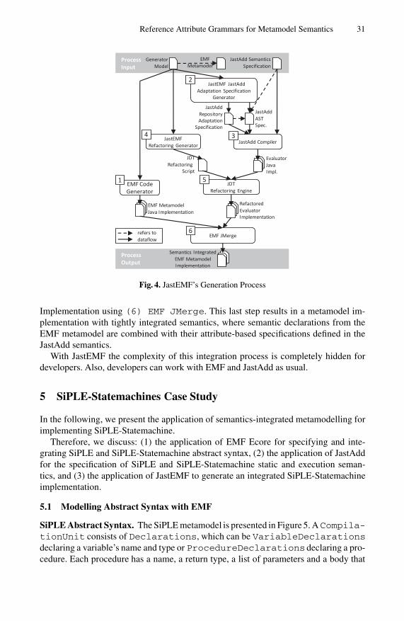
Reference Attribute Grammars for Metamodel Semantics 31
Process Output
ProcessInput
EMF Metamodel
GeneratorModel
JastAdd SemanticsSpecification
JastAdd Compiler
EvaluatorJavaImpl.
JastEMFRefactoring Generator
JDTRefactoring
Script
JDTRefactoring Engine
RefactoredEvaluatorImplementation
EMF CodeGenerator
EMF MetamodelJava Implementation
JastEMF JastAddAdaptation Specification
Generator
EMF JMerge
Semantics IntegratedEMF MetamodelImplementation
2
4 3
1 5
6refers todataflow
JastAddAST Spec.
JastAddRepository Adaptation
Specification
Fig. 4. JastEMF’s Generation Process
Implementation using (6) EMF JMerge. This last step results in a metamodel im-plementation with tightly integrated semantics, where semantic declarations from theEMF metamodel are combined with their attribute-based specifications defined in theJastAdd semantics.
With JastEMF the complexity of this integration process is completely hidden fordevelopers. Also, developers can work with EMF and JastAdd as usual.
5 SiPLE-Statemachines Case Study
In the following, we present the application of semantics-integrated metamodelling forimplementing SiPLE-Statemachine.
Therefore, we discuss: (1) the application of EMF Ecore for specifying and inte-grating SiPLE and SiPLE-Statemachine abstract syntax, (2) the application of JastAddfor the specification of SiPLE and SiPLE-Statemachine static and execution seman-tics, and (3) the application of JastEMF to generate an integrated SiPLE-Statemachineimplementation.
5.1 Modelling Abstract Syntax with EMF
SiPLE Abstract Syntax. The SiPLE metamodel is presented in Figure 5. ACompila-tionUnit consists of Declarations, which can be VariableDeclarationsdeclaring a variable’s name and type or ProcedureDeclarations declaring a pro-cedure. Each procedure has a name, a return type, a list of parameters and a body that

32 C. Burger et al.
Fig. 5. SiPLE Metamodel
is a Block. Each Block consists of a Statement sequence. In SiPLE, nearly ev-erything is a Statement, such as While loops, If conditionals, Expressions,Declarations and VariableAssignments. Expressions can be BinaryEx-pressions or UnaryExpressions, whose concrete sub-classes, e.g., Additionand Not, are not presented in the figure. Furthermore, there are primitive expressionssuch as Constants, References and ProcedureCalls.
The metamodel specifies a spanning tree (containment references, non-derived at-tributes) enriched with semantics interfaces (non-containment references, derived at-tributes, operations). For a better understanding, we assigned numbers to different partsof the semantics interfaces declared in the metamodel. Parts that are to be computedby name analysis are marked with 1 , e.g., each VariableAssignment and eachProcedureCall in a well-formed program has a reference pointing to their respec-tive declaration. Parts depending on type analysis are labeled by 2 , e.g., the derived
attribute Type represents the actual type of an Expression. 3 marked parts belongto the constraint checking realization, which currently consists of the IsCorrect andIsCorrectLocal attributes. Parts labeled with 4 (e.g., Interpret()) declarethe execution semantics interface for both runtime evaluation and constant folding.
SiPLE-Statemachine Abstract Syntax. The SiPLE-Statemachine metamodel is pre-sented in Figure 6. A StateMachine consists of a set of State and TransitionDeclarations. Each Transition has a label representing an event that trig-gers the Transition. Furthermore, guard Expressions allow to specify booleanSiPLE expressions as additional conditions for transition triggering and SiPLE Sta-tements allow to annotate actions to states and transitions that are executed when astate is entered or a transition is triggered respectively. Each Transition refers to asource and a target State.

Reference Attribute Grammars for Metamodel Semantics 33
Fig. 6. SiPLE-Statemachine Metamodel
The metamodel’s semantics are an extension of the semantics used for the JastAddstatemachine tutorial in [22]. Again, we assigned numbers to parts of the semantics in-terface. As above, 1 marks parts belonging to name analysis. In SiPLE-Statemachinename analysis is used to compute the actual source and target states from the corre-sponding labels of a Transition object. Further semantics analysis that computesadditional information such as the successor relation and transitive closure of all statesreachable from a given state are labeled by 5 . Parts that are used to parse textual action
and guard labels to appropriate SiPLE fragments are marked with 6 .
5.2 Specifying Semantics with JastAdd
SiPLE Semantics. There are four semantic concerns that completely specify SiPLE’sstatic and execution semantics. With JastAdd, each concern can be specified as an as-pect. A core specification is used to declare each concern’s semantics, i.e., to declareall attributes (cf. Listing 1.2). The actual attribute definitions (the equations) reside inseparate JastAdd specifications6.
Listing 1.2. Excerpt from the SiPLE Core Specification
a s p e c t NameAnalysis { / / [ 1 ] i n F i g u r e 5/ / P r o c e d u r e name s p a c e :inh C o l l e c t i o n<P r o c e d u r e D e c l a r a t i o n> ASTNode . LookUpPDecl ( S t r i n g name ) ;syn P r o c e d u r e D e c l a r a t i o n P r o c e d u r e C a l l . D e c l a r a t i o n ( ) ;syn P r o c e d u r e D e c l a r a t i o n C o m p i l a t i o n U n i t . MainProcedure ( ) ;
/ / V a r i a b l e name s p a c e :inh C o l l e c t i o n<V a r i a b l e D e c l a r a t i o n> ASTNode . LookUpVDecl ( S t r i n g name ) ;syn V a r i a b l e D e c l a r a t i o n R e f e r e n c e . D e c l a r a t i o n ( ) ;syn V a r i a b l e D e c l a r a t i o n V a r i a b l e A s s i g n m e n t . D e c l a r a t i o n ( ) ;
}a s p e c t T y p e A n a l y s i s { / / [ 2 ] i n F i g u r e 5
syn Type V a r i a b l e D e c l a r a t i o n . Type ( ) ;syn Type V a r i a b l e A s s i g n m e n t . Type ( ) ;syn Type P r o c e d u r e R e t u r n . Type ( ) ;syn Type E x p r e s s i o n . Type ( ) ;
}
6 All specifications can be found at www.jastemf.org.

34 C. Burger et al.
a s p e c t C o n s t r a i n t C h e c k i n g { / / [ 3 ] i n F i g u r e 5syn boolean ASTNode . I s C o r r e c t ( ) ;syn boolean ASTNode . I s C o r r e c t L o c a l ( ) ;
}a s p e c t I n t e r p r e t a t i o n { / / [ 4 ] i n F i g u r e 5
p u b l i c a b s t r a c t O b j e c t E x p r e s s i o n . Value ( S t a t e vm) throws I n t e r p r e t a t i o n E x c e p t i o n ;p u b l i c a b s t r a c t vo id S t a t e m e n t . I n t e r p r e t ( S t a t e vm) throws I n t e r p r e t a t i o n E x c e p t i o n ;syn S t a t e C o m p i l a t i o n U n i t . I n t e r p r e t ( ) ;
}
NameAnalysis. SiPLE uses separate block-structured namespaces for variable and pro-cedure declarations. Although there is a single global scope in each Compilation-Unit, each block introduces a new private scope, shadowing declarations in the outsidescope. No explicit symbol tables are required to resolve visible declarations — the ASTis the symbol table.
TypeAnalysis. SiPLE is a statically, strongly typed language. For each kind of expres-sion its type is computed from the types of its arguments, e.g., if an addition has aReal number argument and an Integer argument the computed type will be Real.Types are statically computed for arithmetic operations, assignments, conditionals (If,While), procedure calls and procedure returns.
ConstraintChecking. Each language construct of a SiPLE program can be staticallychecked for local correctness, i.e., whether the node representing the construct satisfiesall its context-sensitive language constraints or not. Of course, these checks are usuallyjust simple constraints specified based on SiPLE’s name and type analysis like “an Ifcondition’s type must be boolean” or “each reference must be declared”. If all nodes ofa (sub)tree — i.e., a program (fragment) — are local correct, the (sub)tree is correct.
Interpretation. SiPLE’s execution semantics is also specified using JastAdd. We ap-plied JastAdd’s ability to use Java method bodies for attribute specifications. This al-lows for a seamless integration of a Java implementation of the operational semanticsand the declarative, RAG-based static semantics analysis. The interpretation is triggeredwith a call to a CompilationUnit’sInterpret() operation that initialises a stateobject representing a stack for procedure frames and traverses the program’s statementsby calling their Interpret(State) operation.
SiPLE-Statemachine Semantics. The SiPLE-Statemachine semantics is mainly speci-fied in three JastAdd aspects which are shown in Listing 1.3. The original source comesfrom [22]. To integrate SiPLE, we additionally introduced a SiPLECompositionaspect.
Listing 1.3. Excerpt from the SiPLE-Statemachine Core Specification
a s p e c t NameAnalys is { / / [ 1 ] i n F i g u r e 6syn l a z y S t a t e T r a n s i t i o n . s o u r c e ( ) ;syn l a z y S t a t e T r a n s i t i o n . t a r g e t ( ) ;inh S t a t e D e c l a r a t i o n . lookup ( S t r i n g l a b e l ) ;syn S t a t e D e c l a r a t i o n . loca lL ookup ( S t r i n g l a b e l ) ;
}
a s p e c t R e a c h a b i l i t y{ / / [ 5 ] i n F i g u r e 6syn E L i s t S t a t e . s u c c e s s o r s ( ) c i r c u l a r [ . . . ] ;
syn E L i s t S t a t e . r e a c h a b l e ( ) c i r c u l a r [ . . . ] ;}

Reference Attribute Grammars for Metamodel Semantics 35
a s p e c t SiPLEComposi t ion { / / [ 6 ] i n F i g u r e 6p u b l i c S t a t e m e n t Ac t ion . g e t A c t i o n S t a t e m e n t ( ) ;p u b l i c E x p r e s s i o n T r a n s i t i o n . g e t G u a r d E x p r e s s i o n ( ) ;p u b l i c S t a t e m e n t T r a n s i t i o n . g e t A c t i o n S t a t e m e n t ( ) ;
}
NameAnalysis. In SiPLE-Statemachine, name analysis maps textual labels in transi-tions to states. Since states are not block-structured, all declarations of the statemachineare traversed and each state label is compared to the looked up label. Note that a graph-ical editor may set a transition’s source and target state directly.
Reachability. The synthesized successor attribute computes a state’s direct succes-sor relation from the set of declared transitions. In contrast to the original example, wedeclared the attribute to be an EList to achieve better graphical editor support andas circular because of editor notifications issues. Based on the successor relation, thereachable attribute computes a state’s transitive closure, which can be displayed ondemand in a graphical editor we generated for SiPLE-Statemachines.
SipleComposition. This helper aspect uses the SiPLE parser to parse and embed SiPLEExpressions and SiPLE Statements for guard and action labels. Actually, theseparts belong to SiPLE and are integrated into SiPLE-Statemachine (cf. 6). However,since JastAdd does not support packages and always generates AST classes for thegiven AST specifications instead of reusing classes from existing packages as supportedby the EMF, we had to model them as attributes.
5.3 Integration with Further Metamodelling Tools
To prepare the evaluation of JastEMF’s integration approach we applied several meta-modelling tools for further implementation tasks. As our focus is about the specificationof semantics for metamodels using RAGs, we shortly describe their purpose but referto respective publications for details:
– To generate a parser and an advanced text editor for SiPLE we use EMFText [9].Amongst others, the generated editor supports syntax highlighting, code comple-tion, outline and a properties view.
– To provide a graphical syntax for SiPLE-Statemachine we used EuGENia7, a toolthat processes specific metaclass annotations to generate based on their informa-tion (node or transition, shape, style, color, etc.) an according set of GMF [2] spec-ifications. From such specifications the GMF framework then generates a well-integrated, powerful graphical editor for the SiPLE-Statemachine language (cf.Figure 2).
– To make SiPLE-Statemachine executable, we use an XPand [7] template to gener-ate plain SiPLE code, which can be executed by a call to its CompilationUnit’sInterpret operation.
7 http://www.eclipse.org/gmt/epsilon/doc/articles/eugenia-gmf-tutorial/
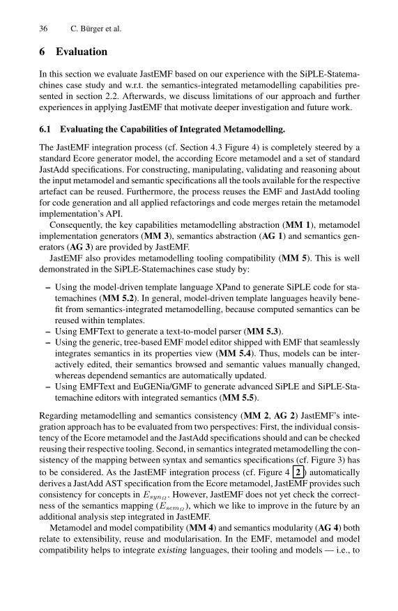
36 C. Burger et al.
6 Evaluation
In this section we evaluate JastEMF based on our experience with the SiPLE-Statema-chines case study and w.r.t. the semantics-integrated metamodelling capabilities pre-sented in section 2.2. Afterwards, we discuss limitations of our approach and furtherexperiences in applying JastEMF that motivate deeper investigation and future work.
6.1 Evaluating the Capabilities of Integrated Metamodelling.
The JastEMF integration process (cf. Section 4.3 Figure 4) is completely steered by astandard Ecore generator model, the according Ecore metamodel and a set of standardJastAdd specifications. For constructing, manipulating, validating and reasoning aboutthe input metamodel and semantic specifications all the tools available for the respectiveartefact can be reused. Furthermore, the process reuses the EMF and JastAdd toolingfor code generation and all applied refactorings and code merges retain the metamodelimplementation’s API.
Consequently, the key capabilities metamodelling abstraction (MM 1), metamodelimplementation generators (MM 3), semantics abstraction (AG 1) and semantics gen-erators (AG 3) are provided by JastEMF.
JastEMF also provides metamodelling tooling compatibility (MM 5). This is welldemonstrated in the SiPLE-Statemachines case study by:
– Using the model-driven template language XPand to generate SiPLE code for sta-temachines (MM 5.2). In general, model-driven template languages heavily bene-fit from semantics-integrated metamodelling, because computed semantics can bereused within templates.
– Using EMFText to generate a text-to-model parser (MM 5.3).– Using the generic, tree-based EMF model editor shipped with EMF that seamlessly
integrates semantics in its properties view (MM 5.4). Thus, models can be inter-actively edited, their semantics browsed and semantic values manually changed,whereas dependend semantics are automatically updated.
– Using EMFText and EuGENia/GMF to generate advanced SiPLE and SiPLE-Sta-temachine editors with integrated semantics (MM 5.5).
Regarding metamodelling and semantics consistency (MM 2, AG 2) JastEMF’s inte-gration approach has to be evaluated from two perspectives: First, the individual consis-tency of the Ecore metamodel and the JastAdd specifications should and can be checkedreusing their respective tooling. Second, in semantics integrated metamodelling the con-sistency of the mapping between syntax and semantics specifications (cf. Figure 3) hasto be considered. As the JastEMF integration process (cf. Figure 4 2 ) automaticallyderives a JastAdd AST specification from the Ecore metamodel, JastEMF provides suchconsistency for concepts in EsynΩ . However, JastEMF does not yet check the correct-ness of the semantics mapping (EsemΩ ), which we like to improve in the future by anadditional analysis step integrated in JastEMF.
Metamodel and model compatibility (MM 4) and semantics modularity (AG 4) bothrelate to extensibility, reuse and modularisation. In the EMF, metamodel and modelcompatibility helps to integrate existing languages, their tooling and models — i.e., to

Reference Attribute Grammars for Metamodel Semantics 37
reuse existing metamodel implementations. Therefore, Ecore supports importing andreferencing metaclasses and their implementation from other metamodels. For suchreuse scenarios JastAdd has no appropriate mechanism. AST specifications can be com-bined from several specifications, but JastAdd always generates a new evaluator imple-mentation and does not support the reuse of existing AST classes and their semantics.Consequently, reuse can only be achieved on the specification, but not implementationlevel. This limitation could be addressed by extending the JastAdd AST specificationlanguage with a packaging and package import concept that conforms to Ecore’s meta-model imports8.
On the other hand, JastAdd’s aspect mechanism and weaving capabilities permitsemantic extensions of languages by contributing new attributes (and node types) toan existing abstract syntax. As the EMF does not support the external contribution ofstructural features to existing metaclasses, the original metamodel needs to be changedto incorporate semantic extensions. This is a severe drawback considering incrementalmetamodel evolution that motivates further research on advancing modularity in futuremetamodelling approaches.
6.2 Limitations and Further Issues
JastAdd Rewrite Issues. JastAdd is not only a RAG system, but also supports local,constrained rewrites that are executed as soon as a node with an applicable rewrite isaccessed. Within rewrites new nodes can be constructed and existing ones rearranged.We observed that in EMF such AST rearrangements in the combination with tree copiescan lead to broken ASTs. Therefore, JastEMF does not support JastAdd rewrites.
Semantics of Incomplete Models. In dynamic environments such as the EMF, syntac-tically incomplete models are common throughout editor sessions. However, semanticsof syntactically erroneous models are not defined and typically their evaluation failswith an exception. To our experience, most interactive modelling tools do not shieldeditor users before such exceptions. There is a need for more sensitive consideration ofsemantics in metamodelling frameworks and associated tooling, such that users are notdisturbed by semantic exceptions caused by syntactically erroneous structures.
For future work, we consider the investigation of incremental AGs [23,24], whichtrace attribute dependencies to reduce the recomputation overhead in the presence offrequent context information changes, to address these issues. Metamodelling toolscould use their attribute dependency knowledge to decide whether an attribute is de-fined or not. If an attribute is not defined — i.e., depends on missing model parts — itsevaluation could be delayed to prevent it from throwing an exception.
In summary, we think, that JastEMF’s benefits clearly outweigh the remaining tech-nical problems. It demonstrates, that RAGs contribute declarativeness, well-foundness,generativeness and ease of specification for semantics-integrated metamodelling. Onthe other hand, metamodels and their accompanying frameworks provide convenient
8 To by-pass the problem, we introduced simple helper properties and attributes in the SiPLE-Statemachines case study. The properties hold specified entry actions, guard expressions andtransition actions as ordinary Java strings whereas the attributes initialise SiPLE’s parser totransform these strings into appropriate SiPLE ASTs.

38 C. Burger et al.
means to specify the API of AG generated tools and prepare their integration into soft-ware development platforms.
7 Related Work
There are a number of approaches related to and dealing with metamodel semantics.In particular we distinguish related work that (1) can benefit from our approach, likeconcrete syntax mapping tools and (2) propose alternative solutions, like constraintlanguages, integrated metamodelling environments, graph-grammars or abstract statemachines. In the following we investigate each of them.
Textual concrete syntax mapping tools like EMFText [9] and MontiCore [10] com-bine existing parser generator technology with metamodelling technology to realizetext-to-model parser generators [25]. They enable users to generate powerful text edi-tors including features such as code completion and pretty printing. However, semanticsanalysis is often neglected or involves proprietary meachanims for implementing a sub-set of static semantics like name analysis manually. Such tools could immediately profitfrom our integration of formal semantics in metamodelling.
Constraint languages. like the OCL [16] or XCheck [7] enable the specificationof well-formedness constraints on metamodels. The rationale behind OCL is to de-fine invariants that check for context-sensitive well-formedness of models and to com-pute simple derived values. However we are not aware of any application of OCL forthe specification of complete static semantics. In comparison AGs do not focus onconstraint definitions, but are widely applied for semantics specification and provideadvanced means to efficiently derive the context-sensitive information language con-straints usually depend on9.
Integrated metamodelling environments. provide dedicated languages to specify ab-stract syntax and semantics but often lack a formal background. Usually semantics haveto be specified using a special constraint language and a special operational (i.e. imper-ative) programming language, both tightly integrated with a metamodelling languageand its framework.
A typical representative is Kermeta [27]. A language in Kermeta is developed byspecifying its abstract syntax with an Essential MOF (EMOF) metamodel and static se-mantics with OCL constraints. Execution semantics can be implemented using a thirdimperative programming language. Abstract syntax, static semantics and execution se-mantics are developed in modules that can be combined using Kermeta’s aspect lan-guage. The modularization concept supported by Kermeta’s aspect language seems verysimilar to the aspect concept of JastAdd: They both support the separation of cross-cutting semantic concerns. Additionally, Kermeta and JastEMF projects immediatelybenefit from EMF tooling in Eclipse.
Our main concern about such integrated metamodelling environments is the over-head for developers to learn and apply all their different proprietary languages. Webelieve that JastAdd’s seamless integration with Java has two main benefits: (1) one
9 E.g., consider the specification of a data-flow analysis as presented in [26].

Reference Attribute Grammars for Metamodel Semantics 39
can rely on Java’s standardised and well-known semantics and (2) the smooth learningcurve from Java to declarative semantics specification reduces the initial effort for usingJastAdd.
Graph-grammars are a convenient approach not only to specify structures — i.e.metamodels’ abstract syntax — but also operations on these structures — i.e. meta-model semantics. Given such specifications, graph rewrite systems can be used to de-rive appropriate repository implementations and semantics [28]. The main advantagesof the graph-grammar approach are its well-founded theoretical background and its uni-form character where syntax and semantics can be specified within a single formalism.
PROGRESS. An important research project, that exploited graph-grammars for tooldevelopment and integration, has been the IPSEN project [28]. Its programminglanguage PROGRESS (PROgramming with Graph REwriting Systems) supportsthe specification of graph schemas (i.e. metamodels), graph queries and graph trans-formations (i.e. semantics). PROGRESS graph schemas rely on attributed graphgrammars to specify node attributes and their derived values. Though, attributedgraph-grammars should not be confused with AGs. Attributed graph-grammarshave no distinction between inherited and synthesized attributes and consequentlylack many convenient AG concepts like broadcasting. In summary, the IPSENproject demonstrated, that graph-grammars are a convenient formalism to specifya broad range of tools and automatically integrate their repositories and semantics.
FUJABA. A more recent graph rewriting tool is FUJABA [29], which integrates Uni-fied Modelling Language (UML) class diagrams and graph rewriting to specifysemantics of class operations. It provides story driven modelling as a visual lan-guage to define rewrite rules, which can be compared to UML activity diagrams.MOFLON [30] adapts FUJABA to support the Meta Object Faclility (MOF) as amodelling language.
In general we think, that graph-rewriting systems are harder to understand than AGs.Given a set of rewrite rules, it is complicated to foresee all possible consequences oftheir application on start graphs. Rewrite results usually depend on the order of ruleapplications. To solve this problem, it is necessary to ensure that the rewrite systemis confluent, which implies a lot of additional effort, not only for the proof of conflu-ence, but also for the design of appropriate stratification rules. On the other hand, AGsrequire a basic context-free structure or a spanning tree they are defined on whereasgraph rewriting does not rely on such assumptions. Furthermore, RAGs can only addinformation to an AST but not remove them or even change its structure. However,there are AG concepts such as higher order attributes [15] (non-terminal attributes inJastAdd) or JastAdd’s local rewrite capabilities which improve in that direction.
Abstract State Machines (ASMs) are a theoretically backed approach to specify exe-cution semantics [14]. For the specification of metamodel semantics they were recentlyapplied in [31] to define sets of minimal modelling languages with well defined ASMsemantics — so called semantic units. The semantics of an arbitrary modelling languageL can now be defined by a mapping of L to such semantic units (semantic anchoring).Of course, the transformation to semantic units and context-sensitive well-formedness

40 C. Burger et al.
constraints (i.e., static semantics) still have to be defined using other approaches. Thus,ASMs and our RAG approach complement each other for the purpose to specify meta-models’ execution and static semantics.
8 Conclusion
In this paper we presented the application of RAGs for metamodel semantics. Wesketched necessary foundations — essentially that most metamodelling languages canbe decomposed into context-free and context-sensitive language constructs — and pre-sented JastEMF, an example integration of the EMF metamodelling framework andthe JastAdd RAG system. Finally, we demonstrated and evaluated the advantages andlimitations of our approach by a case study, which is exemplary for both compiler con-struction (SiPLE) and metamodelling (statemachines). This shows, that for MDSD thewell-investigated formalism of RAGs is a valuable approach for specifying metamodelsemantics and on the other hand, MDSD introduces interesting application areas andnew challenges for RAG tools.
Acknowledgments
This research was funded by the European Social Fond in cooperation with the FreeState of Saxony within the Ph.D. project Innovative Werkzeugarchitekturen fur dieErstellung von IT-Produktlinien im Bereich eingebetteter Software, the Deutsche For-schungsgemeinschaft (DFG, German Research Foundation) within the project Hyper-Adapt, and the European Commission within the FP7 project MOST #216691.
We also like to thank Gorel Hedin for her support and valuable comments, especiallyw.r.t. AGs and JastAdd.
References
1. Selic, B.: The Theory and Practice of Modeling Language Design for Model-Based SoftwareEngineering – A Personal Perspective. In: Lammel, R. (ed.) GTTSE 2009. LNCS, vol. 6491,pp. 290–321. Springer, Heidelberg (2011)
2. Steinberg, D., Budinsky, F., Paternostro, M., Merks, E.: EMF – Eclipse Modeling Frame-work, 2nd edn. Addison-Wesley, Reading (2008)
3. Hedin, G.: Reference Attributed Grammars. Informatica (Slovenia) 24(3), 301–317 (2000)4. Knuth, D.E.: Semantics of Context-Free Languages. Theory of Computing Systems 2(2),
127–145 (1968)5. Ekman, T., Hedin, G.: The JastAdd system — modular extensible compiler construction.
Science of Computer Programming 69(1-3), 14–26 (2007)6. ATLAS Group: ATLAS Transformation Language (ATL) User Guide (2006),
http://wiki.eclipse.org/ATL/User_Guide7. Efftinge, S., et al.: openArchitectureWare User Guide v.4.3.1 (2008),
http://www.openarchitectureware.org/pub/documentation/4.3.1/8. Oldevik, J.: MOFScript User Guide v.0.8 (2009),
http://www.eclipse.org/gmt/mofscript/doc/MOFScript-User-Guide-0.8.pdf

Reference Attribute Grammars for Metamodel Semantics 41
9. Heidenreich, F., Johannes, J., Karol, S., Seifert, M., Wende, C.: Derivation and Refinementof Textual Syntax for Models. In: Paige, R.F., Hartman, A., Rensink, A. (eds.) ECMDA-FA2009. LNCS, vol. 5562, pp. 114–129. Springer, Heidelberg (2009)
10. Krahn, H., Rumpe, B., Volkel, S.: MontiCore: Modular Development of Textual DomainSpecific Languages. In: TOOLS 2008 (Objects, Components, Models and Patterns). LNBIP,vol. 11, pp. 297–315. Springer, Heidelberg (2008)
11. Efftinge, S., Volter, M.: oAW xText: A framework for textual DSLs. In: Workshop on Mod-eling Symposium at Eclipse Summit (2006)
12. Kolovos, D.S.: Editing EMF models with Exeed (EXtended Emf EDitor) (2007),http://www.eclipse.org/gmt/epsilon/doc/Exeed.pdf
13. Ekman, T.: Extensible Compiler Construction. PhD thesis, University of Lund (2006)14. Borger, E., Stark, R.F.: Abstract State Machines: A Method for High-Level System Design
and Analysis. Springer, Heidelberg (2003)15. Vogt, H.H., Swierstra, D., Kuiper, M.F.: Higher Order Attribute Grammars. In: PLDI 1989,
pp. 131–145. ACM, New York (1989)16. OMG: Object constraint language, version 2.2 (2010),
http://www.omg.org/spec/OCL/2.2/17. Farrow, R.: Automatic Generation of Fixed-Point-Finding Evaluators for Circular, but Well-
defined, Attribute Grammars. In: SIGPLAN 1986, pp. 85–98. ACM, New York (1986)18. Boyland, J.T.: Remote attribute grammars. Journal of the ACM 52(4), 627–687 (2005)19. Magnusson, E.: Object-Oriented Declarative Program Analysis. PhD thesis, University of
Lund (2007)20. Kiczales, G., Hilsdale, E., Hugunin, J., Kersten, M., Palm, J., Griswold, W.G.: An Overview
of AspectJ. In: Lee, S.H. (ed.) ECOOP 2001. LNCS, vol. 2072, pp. 327–353. Springer, Hei-delberg (2001)
21. Burger, C., Karol, S.: Towards Attribute Grammars for Metamodel Semantics. Technicalreport, Technische Universitat Dresden (2010) ISSN 1430-211X
22. Hedin, G.: Generating Language Tools with JastAdd. In: Lammel, R. (ed.) GTTSE 2009.LNCS, vol. 6491. Springer, Heidelberg (2011)
23. Reps, T., Teitelbaum, T., Demers, A.: Incremental Context-Dependent Analysis forLanguage-Based Editors. ACM (TOPLAS) 5(3), 449–477 (1983)
24. Maddox III, W.H.: Incremental Static Semantic Analysis. PhD thesis, University of Califor-nia at Berkeley (1997)
25. Goldschmidt, T., Becker, S., Uhl, A.: Classification of Concrete Textual Syntax MappingApproaches. In: Schieferdecker, I., Hartman, A. (eds.) ECMDA-FA 2008. LNCS, vol. 5095,pp. 169–184. Springer, Heidelberg (2008)
26. Nilsson-Nyman, E., Hedin, G., Magnusson, E., Ekman, T.: Declarative Intraprocedural FlowAnalysis of Java Source Code. Electron. Notes Theor. Comput. Sci. 238(5), 155–171 (2009)
27. Muller, P., Fleurey, F., Jezequel, J.: Weaving Executability into Object-Oriented Meta-languages. In: Briand, L.C., Williams, C. (eds.) MoDELS 2005. LNCS, vol. 3713, pp. 264–278. Springer, Heidelberg (2005)
28. Nagl, M. (ed.): Building Tightly Integrated Software Development Environments: TheIPSEN Approach. LNCS, vol. 1170. Springer, Heidelberg (1996)
29. Nickel, U., Niere, J., Zundorf, A.: The FUJABA environment. In: ICSE 2000, pp. 742–745.ACM, New York (2000)
30. Amelunxen, C., Konigs, A., Rotschke, T., Schurr, A.: MOFLON: A Standard-CompliantMetamodeling Framework with Graph Transformations. In: Rensink, A., Warmer, J. (eds.)ECMDA-FA 2006. LNCS, vol. 4066, pp. 361–375. Springer, Heidelberg (2006)
31. Chen, K., Sztipanovits, J., Abdelwalhed, S., Jackson, E.K.: Semantic Anchoring with ModelTransformations. In: Hartman, A., Kreische, D. (eds.) ECMDA-FA 2005. LNCS, vol. 3748,pp. 115–129. Springer, Heidelberg (2005)

Modelling GLL Parser Implementations
Adrian Johnstone and Elizabeth Scott
Royal Holloway, University of London, Egham, Surrey, TW20 0EX, UK{a.johnstone,e.scott}@rhul.ac.uk
Abstract. We describe the development of space-efficient implementa-tions of GLL parsers, and the process by which we refine a set-theoreticmodel of the algorithm into a practical parser generator that creates prac-tical parsers. GLL parsers are recursive descent-like, in that the structureof the parser’s code closely mirrors the grammar rules, and so grammars(and their parsers) may be debugged by tracing the running parser ina debugger. While GLL recognisers are straightforward to describe, fullGLL parsers present technical traps and challenges for the unwary. Inparticular, naıve implementations based closely on the theoretical de-scription of GLL can result in data structures that are not practical forgrammars for real programming language grammars such as ANSI-C.We develop an equivalent formulation of the algorithm as a high-levelset-theoretic model supported by table-based indices, in order to thenexplore a set of alternative implementations which trade space for timein ways which preserve the cubic bound.
Keywords: GLL parsing, general context-free parsing, implementationspaces, time-space tradeoffs.
1 The Interaction between Theory and Engineering
In Computer Science, the theoretician is mostly concerned with the correct-ness and asymptotic performance of algorithms whereas the software engineerdemands ‘adequate’ time complexity on typical data coupled to memory re-quirements that do not cause excessive swapping. The theoretician’s concernsare independent of implementation but the engineer’s concerns are dominatedby it and so the two communities do not always communicate well. As a result,our discipline has not yet achieved the comfortable symbiosis displayed by, forexample, theoretical and experimental physicists.
The dominant characteristic of theoretically-oriented presentations of algo-rithms is under specification. It is fundamental practice for a theoretician tospecify only as much as is required to prove the correctness of the results becausethis gives those results the widest possible generality, and thus applicability.
For the software engineer, under specification can be daunting: they mustchoose data structures that preserve the asymptotic performance demonstratedby the theoretical algorithm, and sometimes the performance expectations areonly implicit in the theoretician’s presentation. For instance, theoretical algo-rithms will often use sets as a fundamental data type. To achieve the lowest
B. Malloy, S. Staab, and M. van den Brand (Eds.): SLE 2010, LNCS 6563, pp. 42–61, 2011.c© Springer-Verlag Berlin Heidelberg 2011

Modelling GLL Parser Implementations 43
asymptotic bounds on performance the algorithm may need sets that have con-stant lookup time (which suggests an array based implementation) or sets whosecontents may be iterated over in time proportional to their cardinality (whichsuggests a linked list style of organisation). The engineer may in fact be lessconcerned by the asymptotic performance than the average case performance ontypical cases, and so a hash-table based approach might be appropriate. Theseimplementation issues may critically determine the take up of a new techniquebecause in reworking the algorithm to accommodate different data representa-tions, the implementer may introduce effects that make the algorithm incorrect,slow or impractically memory intensive in subtle cases.
This paper is motivated by our direct experience of the difficulties encounteredwhen migrating a theoretically attractive algorithm to a practical implementa-tion even within our own research group, and then the further difficulties ofcommunicating the results and rationale for that engineering process to collab-orators and users.
The main focus of this paper is a modelling case study of our GLL generalisedparsing algorithm [6] which yields cubic time parsers for all context free gram-mars. Elsewhere we have presented proofs of correctness and asymptotic boundson performance along with preliminary results that show excellent average caseperformance on programming language grammars. It is clear, however, that thetheoretical presentations have proved somewhat difficult for software engineers,who may find the notation opaque or some of the notions alien, and who maymiss some of the critical assumptions concerning data structures which are re-quired to have constant lookup time. Direct implementation of these structuresconsumes cubic memory and thus more subtle alternatives are required. In thispaper we shall explicitly address the motivation for our choice of high level datastructures, and explain how we migrate a naıve version to a production versionby successive refinement. Our goal is to describe at the meta-level the processby which we refine algorithm implementations.
We view this as a modelling process. Much of the model-driven engineeringliterature is concerned with programming in the large, that is the composition ofcomplete systems from specifications at a level of abstraction well away from theimplementation platform, potentially allowing significant interworking and reuseof disparate programming resources. This paper is focused on programming inthe small. We use a specification language that avoids implementation details ofthe main data structures, and then use application specific measures to refinethe specification into an implementation with optimal space-time tradeoff. Wedo this in a way that lends itself to automation, holding out the prospect of(semi-)automatic exploration of the implementation space. It is worth investingthis effort because we are optimising a meta-program: our GLL parser generatorgenerates GLL parsers, and every parser user will benefit from optimisationsthat we identify.
Our models are written in LC, a small object-oriented language with anextremely simple type system based on enumerations and tables. Our goal is todevelop a notation that is comfortable for theoretical work from which
44 A. Johnstone and E. Scott
implementations may be directly generated, and which also allows tight speci-fication of memory idioms so that the generated implementations can be tunedusing the same techniques that we presently implement manually, but with muchreduced clerical overhead.
We begin with a discursive overview of GLL and then describe some aspectsof the LC language. We give an example GLL parser written in LC and explainits operation. We then show how memory consumption may be significantlyreduced without incurring heavy performance penalties. We finish by discussingthe potential to semi-automatically explore the space of refined implementationsin search of a good time-space trade off for particular kinds of inputs.
2 General Context Free Parsing and the GLL Algorithm
Parsing is possibly one of the most well studied problems in computer sciencebecause of the very broad applicability of parsers, and because formal languagetheory offers deep insights onto the nature of the computational process. Trans-lators such as compilers take a program written in a source (high level) languageand output a program with the same meaning written in a target (machine) lan-guage. The syntax of the source language is typically specified using a contextfree grammar and the meaning, or semantic specification, of a language is typi-cally built on the syntax. Thus the first stage of compilation is, given an inputprogram, to establish its syntactic structure. This process is well understood andthere exist linear algorithms for large classes of grammars and cubic algorithmsthat are applicable to all context free grammars.
Formally, a context free grammar (CFG) consists of a set N of non-terminalsymbols, a set T of terminal symbols, an element S ∈ N called the start symbol,and a set of grammar rules of the form A ::= α where A ∈ N and α is a string in(T ∪N)∗. The symbol ε denotes the empty string, and in our implementationswe will use # to denote ε. We often compose rules with the same left hand sidesinto a single rule using the alternation symbol, A ::= α1 | . . . | αt. We refer tothe strings αj as the alternates of A.
We use a grammar Γ to define a language which is a set of strings of ter-minals. We do this by starting with the start symbol and repeatedly replacinga nonterminal with one of its alternates until a string containing no nonter-minals is obtained. A derivation step is an expansion γAβ⇒γαβ where γ, β ∈(T∪N)∗ and A ::= α is a grammar rule. A derivation of τ from σ is a sequenceσ⇒β1⇒β2⇒ . . .⇒βn−1⇒τ , also written σ
∗⇒τ or, if n > 0, σ+⇒τ . The language
defined by a CFG Γ is the set of all strings u of terminals which can be derivedfrom the start symbol, S, of Γ . Parsing is the process of determining, given astring u, some or all of the derivations S
∗⇒u.Of the linear parsing techniques perhaps the most widely used is the LR-table
driven stack based parser [3]. For the class of grammars which admit LR-parsersthe technique is straightforward to implement. However, the class of grammarsdoes not include any grammars for ‘real’ programming languages and as a resultimplementations ‘modify’ the technique to extend its applicability. It can be

Modelling GLL Parser Implementations 45
hard to reason about the correctness or the subtle behaviour of the resultingimplementation.
An alternative is to use a general technique such as Earley[2], CYK[10] orGLR[8], [5]. In worst case Earley algorithms are cubic, CYK requires the gram-mar to be rewritten in 2-form and standard GLR algorithms are unbounded poly-nomial order, although the typical performance of GLR algorithms approacheslinear and a cubic version has been developed [7]. These general algorithms areused in the natural language community but have had relatively limited take upwithin mainstream computer science. This is, at least to some extent, becausethey are hard for many implementers to understand and their implementationneeds to be done with a great deal of care to get acceptable space and runtimeperformance. For example, ASF+SDF [9] uses Farshi’s version of GLR [4] whichachieves correctness in a rather brute force way and hence acquires a perfor-mance cost, and Bison includes a GLR mode [1] which does not employ the fulldetails of the GLR approach and hence cannot parse an input of length 20 forsome highly ambiguous grammars.
Recently we have introduced the general GLL parsing technique [6], whichis based on the linear recursive descent paradigm. Recursive descent (RD) isan attractive technique because the parser’s source program bears a close rela-tionship to the grammar of the language and hence is easy to reason about, forinstance by tracing the code in a debugger. However, the class of grammars towhich RD can be applied is very limited and many extensions have been im-plemented which use either full or limited backtracking. Full backtracking canresult in exponential runtime and space requirements on some grammars andlimited backtracking will fail to parse some grammars correctly. GLL modelsfull backtracking by maintaining multiple process threads. The worst-case cubiccomplexity is achieved by using a Tomita-style graph structured stack (GSS) tohandle the function call stacks and left recursion (a fundamental problem for RDparsers) is handled with loops in this graph. (A non-terminal A is left recursiveif there is a string μ such that A
+⇒Aμ, and a grammar is left recursive if it hasa left recursive nonterminal.)
The GLL technique is based on the idea of traversing the grammar, Γ , usingan input string, u, and we have two pointers one into Γ and one into u. Wedefine a grammar slot to be a position immediately before or after any symbolin any alternate. These slots closely resemble LR(0) items and we use similarnotation, X ::= x1 . . . xi · xi+1 . . . xq denotes the slot before the symbol xi+1.The grammar pointer points to a grammar slot. The input pointer points to aposition immediately before a symbol in the input string. For u = x1 . . . xp, i isthe position immediately before xi+1 and p is the position immediately beforethe end-of-string symbol, which we denote by $.
A grammar is traversed by moving the grammar pointer through the grammar.At each stage the grammar pointer will be a slot of the form X ::= α · xβ orX ::= α· and the input pointer will be an input position, i. There are thenfour possible cases: (i) If x = ai+1 the grammar pointer is moved to the slotX ::= αx · β and the input pointer is moved to i + 1. (ii) If x is a nonterminal

46 A. Johnstone and E. Scott
A then the ‘return’ slot, X ::= αx · β is pushed onto a stack, the grammarpointer is moved to some slot of the form A ::= ·γ and the input pointer isunchanged. (iii) If the grammar pointer is X ::= α· and the stack is nonempty,the slot Y ::= δX · μ which will be on the top of the stack is popped and thisbecomes the grammar pointer. (iv) Otherwise if grammar pointer is of the formS ::= τ · and the input pointer is at the end of the input a successful traversalis recorded, else the traversal is terminated in failure. Initially the grammarpointer is positioned at a slot S ::= ·α, where S is the start symbol, and theinput pointer is 0.
Of course we have not said how the slot A ::= ·γ in case (ii) is selected.In the most general case this choice is fully nondeterministic and there can beinfinitely many different traversals for a given input string. We can reduce thenondeterminism significantly using what we call selector sets. For a string α andstart symbol S we define firstT(α) = {t|α ∗⇒tα′}, and first(α) = firstT(α)∪{ε} if α
∗⇒ε and first(α) = firstT(α) otherwise. We also define follow(α) ={t|S ∗⇒ταtμ} if α �= S and follow(S) = {t|S ∗⇒τStμ} ∪ {$}.
Then for any slot X ::= α · β we define select(X ::= α · β) to be the union ofthe sets first(βx), for each x ∈ follow(X), and we can modify the traversalcase (ii) above to say (ii) If x is a nonterminal A and there is a grammar slotA ::= ·γ where ai ∈ select(γ) then the ‘return’ slot, X ::= αx · β is pushed ontoa stack, the grammar pointer is moved to the slot A ::= ·γ and the input pointeris unchanged. The initial grammar pointer is also set to a slot S ::= ·α wherea0 ∈ select(A ::= ·α).
Whilst the use of selector sets can significantly reduce the number of possiblechoices at step (ii), in general there will still be more than one qualifying slotA ::= ·γ and, in some cases, infinitely many traversals. GLL is a techniquedesigned to cope with this in worst-case cubic time and space.
At step (ii), instead of continuing the traversal each possible continuation pathis recorded in a context descriptor and ultimately pursued. We would expect adescriptor to contain a slot, an input position and a stack. Then, at step (ii), foreach slot A ::= ·γ such that ai ∈ select(A ::= ·γ) a descriptor is created with thatslot, the current stack onto which the return slot is pushed and input position i.A descriptor (L, s, i) is ‘processed’ by restarting the traversal with the grammarpointer at the slot L, s as the stack and input pointer at i. There are potentiallyinfinitely many descriptors for a given input string because there are potentiallyinfinitely many stacks. The solution, introduced by Tomita for his initial versionof the GLR technique, is to combine all the stacks into a single graph structure,merging the lower portions of stacks where they are identical and recombiningstack tops when possible. At the heart of the GLL technique are functions forbuilding this graph of merged stacks, which we call the GSS. Instead of a fullstack, descriptors then contain a node of the GSS which corresponds to the topof its associated stack(s), thus one descriptor can record several partial traversalsprovided they restart at the same grammar and input positions.
So far we have addressed only the recognition of a string; we want to capturethe syntactic structure to pass on to later stages in the translation process. A
Modelling GLL Parser Implementations 47
common method for displaying syntactic structure is to use a derivation tree: anordered tree whose root is labelled with the start symbol, leaf nodes are labelledwith a terminal or ε and interior nodes are labelled with a non-terminal, A say,and have a sequence of children corresponding to the symbols in an alternate ofA. This is a derivation tree for a1 . . . an if the leaf nodes are labelled, from left toright, with the symbols a1, . . . , an or ε. The problem is that for ambiguous gram-mars one string may have very many different syntactic structures and so anyefficient parsing technique must use an efficient method for representing these.The method used by GLR parsers is to build a shared packed parse forest (SPPF)from the set of derivation trees. In an SPPF, nodes from different derivation treeswhich have the same tree below them are shared and nodes which correspondto different derivations of the same substring from the same non-terminal arecombined by creating a packed node for each family of children. The size of suchan SPPF is worst-case unbounded polynomial, thus any parsing technique whichproduces this type of output will have at least unbounded polynomial space andtime requirements. The GLL technique uses SPPF building functions that con-struct a binarised form of SPPF which contains additional intermediate nodes.These nodes group the children of packed nodes in pairs from the left so thatthe out degree of a packed node is at most two. This is sufficient to guaranteethe SPPF is worst-case cubic size. In detail, a binarised SPPF has three typesof nodes: symbol nodes, with labels of the form (x, j, i) where x is a terminal,nonterminal or ε and 0 ≤ j ≤ i ≤ n; intermediate nodes, with labels of the form(t, j, i); and packed nodes, with labels for the form (t, k), where 0 ≤ k ≤ n andt is a grammar slot. We shall call (j, i) the extent (j, i are the left and rightextents respectively) of the SPPF symbol or intermediate node and k the pivotof the packed node.
3 The LC Specification Language
LC is a small object oriented language which provides only a single primitive datatype (the enumeration) and a single data structuring mechanism (the table). LCis designed to allow high-level descriptions of set-theory based algorithms whilstalso allowing quite fine grained specification of the implementation in terms ofthe way the algorithm’s objects are to be represented in memory. In this respect,LC is an unusual language with elements of both high level specification lan-guages and very low level assembler-like languages. At present, LC is a (mostly)paper notation which we use here to describe data structure refinements. Ourintention is that an LC processor will be constructed which can generate exe-cutable programs written in C++, Java and so on as well as LATEX renderingsof our algorithms in the style of [6]. (We note in passing that LC’s syntax ishard to parse with traditional deterministic parsers, so in fact LC itself needs aGLL or other general parser). In this section we describe the type system of LCalong with a few examples of sugared operations and control flow sufficient tounderstand the description of the GLL parser below.

48 A. Johnstone and E. Scott
Lexical conventions. An LC program is a sequence of tags and reserved symbols,notionally separated by white space. A tag is analogous to an identifier in aconventional programming language except that any printable character otherthan the nine reserved characters ( ) [ ] , | : " and comments delimitedby (* *) may appear in a tag. Hence adrian , 10 and -3.5 are all validtags. Where no ambiguity results, the whitespace between tags may be omitted.Character strings are delimited by " and may include most of the ANSI-C escapesequences.
Primitive types. The LC primitive data type generator is the enumeration whichmaps a sequence of symbols onto the natural numbers and thus into internal ma-chine integers. The enumeration is a |-delimited list with a prepended tag whichis the type name. A boolean type might be defined as Bool ( false | true ).Literals of this type are written Bool::false and Bool::true. Where no ambi-guity results, the tag may be written simply as the tag true or false. Methodsmay be defined by enumerating the appropriate finite map from the set of inputparameters to the output values, so to define a boolean type that contains alogical and operation we write:
Bool ( false | trueBool &(Bool, Bool) := ( (false, false),
(false, true) ) )
Where no ambiguity results, methods may be invoked using infix notation.Every primitive type has an extra value () read as empty. Newly declared
variables are initialised to () and variables may be ‘emptied’ by assigning () tothem.
We can declare some integer types as
Int3 ( -4 | -3 | -2 | -1 | 0 | 1 | 2 | 3 )Unsigned3 ( 0 | 1 | 2 | 3 | 5 | 6 | 7 )
We shall assume the existence of a type Int which has been defined in thisway and which contains sufficient values to allow our computations to proceedwithout overflow and the usual arithmetic operations.
For each enumeration, the first element maps to 0, the second to 1 and soon. We use |x| to denote the cardinality of set x and ||x|| to represent thememory space required to represent an element of x. If |T | is the number ofexplicitly declared enumeration elements then there are |T |+ 1 elements in thetype (allowing for the extra value () ) and so a value of type T occupies atleast ||t|| = �log2(|T |+ 1)� binary digits in memory.
Enumerations may be composed: BothBoolAndUnsigned3 (Bool |Unsigned3) is a shorthand for
BothBoolAndUnsigned3 ( false | true | 0 | 1 | 2 | 3 | 5 | 6 | 7 )
It is an error to compose enumerations which share tag values.
Modelling GLL Parser Implementations 49
Tables. Each variable in LC is a table with zero or more dimensions each ofwhich has an index set defined by an LC enumeration. So, Bool x(Int3)(Bool)declares a two dimensional array of 16 boolean variables, called x(-3)(false),x(-3)(true), x(-2)(false), . . . , x(3)(true). We may write Bool x(Int3,Bool) as a shorthand declaration.
Representing types with LC tables. Since LC’s type system is so simple, it isreasonable to wonder whether it is sufficient. It clearly is complete in funda-mental engineering terms because nearly all modern computers use a singlevirtual address space of binary memory locations corresponding to a one dimen-sional LC table. All data structures ultimately are mapped to this representation.Hoare’s classic survey of datastructuring techniques listed five mechanisms bywhich primitive types are combined: Cartesian product, discriminated union,map, powerset and recursive data type. LC provides each of these: a comma-delimited list of type and field names, for example CartProd (Int3 i, Boolb), denotes a Cartesian product and corresponds to a record structure in Pascalor a struct in C named CartProd with two fields named i and b; a |-delimitedlist of type and field names, for example DiscUnion (Int3 i | Bool b), de-notes a discriminated union and plays a similar role to a C union; maps aredirectly represented by tables of functions; powersets are represented by tablesindexed by the type of the powerset whose cells are either empty or containthe element of the unusual enumeration type Set (isMember); and recursivetypes by (impractically) large tables: for instance the edges of a graph of nodescontaining a CartProd field is specified as Set g(CartProd, CartProd). Theprocess by which such extensive tables is implemented is described in a latersection.
Assignments. In LC, assignment is central. Simple assignment is written x :=2. Structurally type compatible assignments may be done is a single statementas in (Int3 x, Bool y, Unsigned3 z) := (3, true, 3). We provide somehigher level assignment operations which are used as hints by the datastructurerefinement stage:
x addTo s is shorthand for s(x) := isMemberx deleteFrom s is shorthand for s(x) := ()y selectDelete s is shorthand for: nondeterministically select an index iof an occupied cell in s then execute y := s(i) s(i) := ().y selectNewestDelete s is like selectDelete except that the most re-cently assigned cell is guaranteed to be selected (leading to stack-like be-haviour)y selectOldestDelete s is like selectDelete except that the occupiedcell whose contents has been unchanged the longest is guaranteed to beselected, leading to queue-like behaviour.
Control flow. An LC label may appear before expressions or statements, labelsare denoted by a tag followed by a colon. Labels may be assigned to variables and

50 A. Johnstone and E. Scott
passed as parameters; their type is CodeLabel and there is an implicit definitionof an enumeration comprising all of the labels in a program in the order in whichthey are declared. Control may be transferred to a literal label or the contentsof a CodeLabel variable with the goto statement. LC also includes the usual ifand while statements. LC provides some syntactically sugared predicates suchas x in s which is shorthand for s(x) != (), i.e. that the cell in s indexed byx is non-empty.
The for statement provides a variety of higher level iteration idioms.
for x in T and for x in Y each execute once for each member of theenumeration in type T or non-empty member of table Y respectively; oneach iteration x will have a different element but there is no guarantee of theorder in which elements are used.for x over T and for x over Y each execute once for each member ofthe enumeration in type T or non-empty member of table Y respectively,with the elements being used in the order in which they are declared in Tor, respectively, Y. In the case of a table, where the index is a tuple, therightmost element varies most rapidly.
Text strings and output. LC strings are delimited by " and accept most ANSI-C escape sequences. An LC program can produce textual output via a methodwrite() which, by analogy with ANSI-C’s printf() function takes a string withembedded place holders %. No type need be supplied, since LC values carry theirclass with them, but most ANSI-C formatting conventions are supported.
4 An Example GLL Parser
In this section we discuss an LC GLL parser for the grammar
S ::= A S b | ε A ::= a
In the listing below, data types are declared in lines 1–19 and variables in lines20–30. The GLL parser body is in lines 42–71 and the support routines (whichare grammar independent) are appended in lines 73–111. The dispatcher, whichdictates the order in which contexts are computed is at lines 35–40.
There are primitive types GSSLabel, SPPFLabel and ContextLabel whose el-ements are certain grammar slots together with, in the case of SPPFLabel, thegrammar terminals and nonterminals, and # (epsilon). There are explicit mapscontextLabel, codeLabel, and sppfLabel from GSSLabel to contextLabeland from contextLabel to CodeLabel and sppfLabel. We also define the se-lector sets for each grammar slot, and abort sets which are the complements ofthe selector sets. The maps isSlot1NotEnd and isSlotEnd take a ContexLabeland return a Boolean. The former returns true if the corresponding slot is ofthe form X ::= x · α where x is a terminal or nonterminal and α �= ε, and thelatter returns true if the corresponding slot is of the form X ::= γ·. The maplhsSlot takes a ContextLabel and returns the left hand side nonterminal of

Modelling GLL Parser Implementations 51
the corresponding slot. For readability we have left the explicit definitions of allthese types out of the listing.
The methods findSPPFSymbolNode, findSPPFPackNode and findGGSNode re-turn a node with the specified input attributes, making one if it does not alreadyexist. Their definitions have also been omitted so as not to pre-empt the datastructure implementation discussion presented in the later sections of this paper.
1 Set (isMember)2 N ( A | S )3 T ( a | b )4 Lexeme (T | EndOfString)5 GSSLabel (...)6 SPPFLabel (...)7 ContextLabel (...)8 CodeLabel codeLabel(ContextLabel) := (...)9 ContextLabel contextLabel(GSSLabel) := (...)
10 SPPFLabel sppfLabel(ContextLabel) := (...)11 Set abortSet... := (...)12 Set selectorSet... := (...)13 GSSNode (GSSLabel s, Int i)14 GSS (Set GSSEdge (GSSNode src, SPPFSymbolNode w, GSSNode dst))15 SPPFSymbolNode (SPPFLabel s, Int leftExtent, Int rightExtent)16 SPPFPackNode (SPPFLabel s, Int pivot)17 SPPF (SPPFSymbolNode symbolNode, SPPFPackNode packNode,18 SPPFSymbolNode left, SPPFSymbolNode right)19 Context (Int i, ContextLabel s, GSSNode u, SPPFSymbolNode w)20 GSS gss21 SPPF sppf22 Context c_C (* Current context *)23 Int c_I (* Current input pointer *)24 GSSNode c_U (* Current GSS node *)25 SPPFSymbolNode c_N (* Current SPPF node *)26 SPPFSymbolNode c_R (* Current right sibling SPPF node*)27 GSSnode u_0 (* GSS base node *)28 Set U(Context) (* Set of contexts encountered so far *)29 Set R(Context) (* Set of contexts awaiting execution *)30 Set P(GSSNode g SPPFSymbolNode p) (* Set of potentially unfinished pops *)31 gll_S(32 SPPF parse(Lexeme I(Int))(33 goto L_S34
35 L_Dispatch:36 c_C selectDelete R37 if c_C = () return sppf38 c_I := c_C(i)39 c_N := c_C(w)40 goto codeLabel(c_C(s))41
42 L_A:43 if I(i) in selectorSet_A_1 addContext(A_1, c_U, c_I, ())44 goto L_Dispatch45
46 L_A_1:47 c_R := (a, c_I, c_I + 1) c_N := getSPPFNodeP(A_1_1, c_N, c_R) c_I := c_I + 148 pop49 goto L_Dispatch50
51 L_S:52 if I(i) in selectorSet_S_1 addContext(S_1, c_U, c_I, ())53 if I(i) in selectorSet_S_2 addContext(S_2, c_U, c_I, ())54 goto L_Dispatch55
56 L_S_1:57 c_U := updateGSS(S_1_1) goto L_A58 L_S_1_1:59 if I(c_I) in abortSetS_1_2 goto L_Dispatch

52 A. Johnstone and E. Scott
60 c_U := updateGSS(S_1_2) goto L_S61 L_S_1_2:62 if I(c_I) in abortSetS_1_3 goto L_Dispatch63 c_R := (b, c_I, c_I + 1) c_N := getSPPFNodeP(S_1_3, c_N, c_R) c_I := c_I + 164 pop65 goto L_Dispatch66
67 L_S_2:68 c_R := (#, c_I, c_I) c_N := getSPPFNodeP(S_2_1, c_N, c_R)69 pop70 goto L_Dispatch71 )72
73 Void addContext(ContextLabel s, GSSNode u, Int i, SPPFSymbolNode w)74 if (s, u, w) not in U(i) (75 (s, u, w) addto U(i)76 (s, u, w) addto R(i)77 )78
79 Void pop() (80 if c_U = u_0 return81 (c_U, c_N) addto P82 for (w, u) in gss(c_U)83 addContext(contextLabel(c_U(s)), u, c_I,84 getSPPFNodeP(contextLabel(c_U(s)), w, c_N))85 )86
87 GSSNode updateGSS(ContextLabel s) (88 w := c_N89 v := findGSSNode(s, c_I)90 if (v, w, c_U) not in gss (91 (v , w, c_U) addto gss92 for z in P(v) addContext(s, c_U, z(rightExtent), getSPPFNodeP(s, w, z))93 )94 return v95 )96
97 SPPFSymbolNode getSPPFNodeP(ContextLabel s, SPPFSymbolNode z, SPPFSymbolNode w) (98 if isSlot1NotEnd(s) return w99 SPPFLabel t
100 if isEndSlot(s) t := lhsSlot(s) else t := sppfLabel(s)101 ( , k, i) := w102 if z != SPPFSymbolNode::() (103 y := findSPPFSymbolNode(t, z(leftExtent), i)104 findSPPFPackNode(y, s, k, z, w)105 )106 else (107 y := findSPPFSymbolNode(t, k, i)108 findSPPFPackNode(y, s, k, (), w)109 )110 return y111 )112 )
5 The Impact of Language Size
Programming languages can vary by factor of seven or more in the cardinalityof key enumerations for GLL parsers. Table 1 shows the size of the GSSLabel,SPPFLabel and ContextLabel enumerations for a range of languages. In eachcase we have used the most authoritative available grammar: language stan-dards for ANSI-C, Pascal and C++; the original report for Oberon and the VSCOBOL II grammar recovered from IBM documentation by Ralf Lammel andChris Verhoef.

Modelling GLL Parser Implementations 53
Table 1. GLL measures for programming languages
Grammar Enumeration extents Ring SetsGSS SPPF context length Defined Unique Saving
Oberon 1990 240 645 481 3 442 204 54%C ANSI X3.159-1989 277 665 505 5 507 176 65%Pascal: ISO/IEC 7185:1990 393 918 755 3 626 234 63%Java JLS1.0 1996 384 949 755 4 668 227 66%C++ ISO/IEC 14882:1998 722 1619 1287 4 1351 294 78%COBOL (SDF) 1767 4530 3702 5 3502 863 75%
We also show the grammar’s ring length. This is the longest sequence of ter-minals present in any alternate in the grammar. It turns out that the dimensionsof some tables in a GLL parser may be reduced in size from O(the length of theinput string) to O(ring length).
Finally, we show the effect of set merging. The number of defined sets is thenumber of unique sets referenced by a GLL parser: that is the selector sets andthe abort sets. It turns out that many of these sets have the same contents, sowe can alias names together and only store one table of isMember for two ormore set names.
6 Process Management in GLL
The description of the GLL technique in Section 2 is essentially declarative. Herewe focus on possible implementations of the control-flow in GLL parsing. Theheart of GLL parsing from an operational point of view is the task scheduler. GLLcontexts (line 11) comprise a CodeLabel L, at which to resume execution, andthe input pointer, GSS and SPPF nodes that were current at the time the contextis created. Each of these specifies an instance of the parser process. Whenever aGLL parser encounters potential multiple control flow paths it creates a processcontext for each path and then terminates the current process. This happens intwo places: (i) whilst processing a nonterminal when the selected productionsare added as new processes and (ii) when rules which called a nonterminal arerestarted after a pop action (in either the pop or updateGSS functions).
Now, what is to stop the number of processes growing without limit? Thekey observation is that our parsing process is context free, and this means thatall instances of a nonterminal matching a particular substring are equivalent, orto put it another way, if a nonterminal A has already been matched against aparticular substring α then we do not have to rerun the parse function. Instead,we merely need to locate the relevant piece of SPPF and connect the SPPF nodecurrently under construction to it. As result, each GLL context created withina run of the parser need execute only once. To ensure this, we maintain a set ofcontexts that have been seen on a parse U along with a set R which holds thesubset of U which currently awaits processing.

54 A. Johnstone and E. Scott
Whenever a process terminates, either because it reached the end of a produc-tion or because the current input lexeme is invalid, control returns to L_Dispatchwhere a new process is scheduled for execution. In our example, processes areremoved non-deterministically (line 36). If we force stack removal by changingthe selectDelete operator to selectNewestDelete then we can simulate thebehaviour of a traditional depth-first RD parser except that GLL accepts leftrecursive grammars. This can be very useful for debugging grammars. It turnsout that if we force queue removal using selectOldestDelete then we can makesignificant memory savings, and reduce the maximum size of R.
7 Modelling GLL Data Structure Refinement
So far, our LC programs have been based on the notion of a flexible tableswhich can change their size and even their dimensionality as required. From thetheoretician’s point of view, we assume that the tables are ‘large enough’. Tableelements may be accessed in unit time, and on the occasions that we need toiterate over the contents of a table in time proportional to the number of usedelements, we assume that a parallel linked list has been constructed in tandemwith the table. This model (which we call Big-Fast-Simple or BFS) is sufficientto reason about the asymptotic space and time performance of an algorithm,but is likely to be over-simplistic for real problems, and indeed that is the casefor GLL. It turns out that directly implementing GLL data structures such asthe SPPF and GSS as arrays is practical for small examples, and is in fact veryuseful for experimenting with pathological highly ambiguous grammars becausewe get maximum speed that way, but for realistic inputs to parsers for even smalllanguages such as ANSI-C the direct implementation requires huge memory.
We shall now describe the procedure we use to optimise the space requiredby our data structures with compromising asymptotic behaviour.
7.1 Address Calculation and Pointer Hopping
We might attempt to implement an LC table as a straightforward multi-dimensional array, or as a sparse array made up of a tree of lists, or as somesort of hybrid. An LC table, like any other kind of data structure, is a containerfor other data structures and primitive data types; any instance of a type isultimately just a collection of filled cells along with access paths to each cell,expressed in LC’s case as tuples of indexing expressions.
There are essentially only two mechanisms from which to construct accesspaths: pointer hopping (i.e. linked data structures based on cells which containthe names of other cells) and direct address calculation in which the access path isa computation over the index expressions and some constants. The distinguishingfeature, then, is that with address calculation, a data cell’s address is a functionof its index expression only, but with linking a data cell’s address is a function ofits index expression and the contents of at least one other cell in the data type.
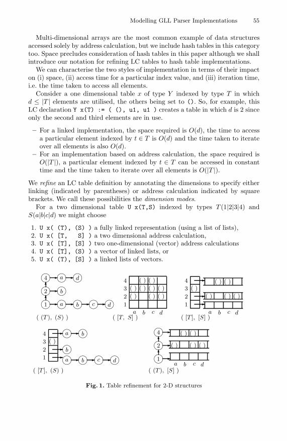
Modelling GLL Parser Implementations 55
Multi-dimensional arrays are the most common example of data structuresaccessed solely by address calculation, but we include hash tables in this categorytoo. Space precludes consideration of hash tables in this paper although we shallintroduce our notation for refining LC tables to hash table implementations.
We can characterise the two styles of implementation in terms of their impacton (i) space, (ii) access time for a particular index value, and (iii) iteration time,i.e. the time taken to access all elements.
Consider a one dimensional table x of type Y indexed by type T in whichd ≤ |T | elements are utilised, the others being set to (). So, for example, thisLC declaration Y x(T) := ( (), u1, u1 ) creates a table in which d is 2 sinceonly the second and third elements are in use.
– For a linked implementation, the space required is O(d), the time to accessa particular element indexed by t ∈ T is O(d) and the time taken to iterateover all elements is also O(d).
– For an implementation based on address calculation, the space required isO(|T |), a particular element indexed by t ∈ T can be accessed in constanttime and the time taken to iterate over all elements is O(|T |).
We refine an LC table definition by annotating the dimensions to specify eitherlinking (indicated by parentheses) or address calculation indicated by squarebrackets. We call these possibilities the dimension modes.
For a two dimensional table U x(T,S) indexed by types T (1|2|3|4) andS(a|b|c|d) we might choose
1. U x( (T), (S) ) a fully linked representation (using a list of lists),2. U x( [T, S] ) a two dimensional address calculation,3. U x( [T], [S] ) two one-dimensional (vector) address calculations4. U x( [T], (S) ) a vector of linked lists, or5. U x( (T), [S] ) a linked lists of vectors.
�
�
�
�
�
�
�
�
�
�
�
�
�
�
�
�
�
�
�
�
4
4
a
a
c
c
d
b
d
d
2
2
b
b
b
b
1
1
a
a
�
�
�
�
�
�
�
�
�
�
�
�
�
�
�
�
�
�
( ) ( )
( )
( ) ( )
( )
( ) ( )
( )
( )( ) ( )
( )
( ) ( )
( )
( )( ) ( )
( )
( )
1 1
1
2 2
2
3 3
3
4 4
4
a a
a
b b
b
c c
c
d d
d
�
�
�
�
�
�
( (T ), (S) )
( [T ], (S) )
( [T, S] )
( (T ), [S] )
( [T ], [S] )
Fig. 1. Table refinement for 2-D structures

56 A. Johnstone and E. Scott
These cases are illustrated in Figure 1 for the case of an 2D array indexed by un-signed two-bit integers containing the following ordered pairs: (1, a),(1, b),(1, c),(1, d), (2, b), (4, a) and (4, d).
For multi-dimensional tables implemented as anything other than a full array,the dimension modes of a table are not the only things that affect performancesince both the size of a table and its access time for particular elements can bedependent on the ordering of the dimensions. We should emphasise that this ispurely an implementation matter: the semantics of a table do not change if onepermutes the indices in its declaration as long as the indices in accesses to thattable are changed to match. This means that we have an opportunity to improveperformance through refinement without affecting the analysis of the algorithmas specified in its original, unrefined, form.
Consider the set of ordered pairs (1, a), (3, a), (4, a) and (4, b). The leftmostdimension uses three distinct values, but the rightmost dimension uses only two.If we use the list-of-lists organisation, indexing as ((T), (S)) we can have twostructures, one listing the leftmost dimension first and the other the rightmost:
� �
�
�
�
� �� �
� �� �
4 a
3
b
4
3 ba 4
1 aa 1
�
� �
�
�
�
�� �
� �
The leftmost-first table requires more space than the rightmost. The driver forthis is the utilisation count for a dimension of a table. If we can order a table sothat, on average, the dimensions with the lowest utilisation counts are used first,then we will on average reduce the size of the table. This effect, in which usingthe dimension with the highest utilisation count first increases the overall size ofthe structure can have a very significant effect on memory consumption. Considerthe case of a table x([Unsigned16], [Unsigned16]). This will comprise vectorsof length 216 elements. Let us imagine an extreme case in which only one row ofthis table is in use, i.e. that we are using cells x(0,0), x(1,0), . . . x(65535, 0).If we use the leftmost dimension as the first (column) index, then we need 65536 row vectors within which only one element is in use. If, on the other hand,we use the rightmost dimension for the column vector then we need only onerow vector, all elements of which are in use. We can see that the space allocationfor a table indexed as ([T], [T]) can vary between 2|T | and |T |2.
Access time can be affected too: if we use a ([Int], (Int)) indexing stylethen the arrangement with the shortest average row list is fastest. This militatesin favour of placing the dimension with the highest utilisation rate first. Thesetwo effects are occasionally in tension with each other, but for sparse tables itturns out that the best organisation is to move all of the [] dimensions to theleft, and then sort the [] left-to-right by reducing utilisation counts and then tosort the () dimensions left-to-right by reducing utilisation count.

Modelling GLL Parser Implementations 57
8 The Modelling Process
Having looked at notation for, and effects of, different organisations we shall nowlook at a real example drawn from the GLL algorithm.
Consider the declaration of the GSS:
GSSNode (GSSLabel s, Int i)
SPPFSymbolNode (SPPFLabel s, Int leftExtent, Int rightExtent)
GSS (Set GSSEdge (GSSNode src, SPPFSymbolNode w, GSSNode dst))
GSS gss
We begin by flattening the declarations into a signature for table gss bysubstitution:
Set gss ((*src*) GSSLabel, Int,
(*w*) SPPFLabel, Int, Int,
(*dst*) GSSLabel, Int
)
This is discouraging: on the face of it the signature for gss demands a sevendimensional table, of which four dimensions are indexed by Int. We can reducethe extent of those dimensions to Natural(n) (a natural number in the range 1to n) since we know that extents and indices are bounded by the length of theparser’s input string. Extents for the other dimensions may be found in Table 1:for ANSI-C there are 277 elements in the GSSLabel enumeration and 665 inthe SPPFLabel enumeration. It is not unreasonable to expect a C compiler toprocess a string of 10,000 (104) tokens: our GSS table would then require at least1016 × 2772 × 665 ≈ 5.1× 1022 bits, which is clearly absurd.
Now, the signature for a data structure may contain dependent indices. Forinstance, in the GSS we can show that the left extent of a GSS edge labelw(leftExtent) is the same as the index of the destination GSS node, and therightExtent is the same as the index of the source node. These repeated dimen-sions can be removed, at which point our signature is reduced to
Set gss ((*src*) GSSLabel, Int,
(*w*) SPPFLabel,
(*dst*) GSSLabel, Int
)
We must now identify dimensions that are candidates for implementation withaddress calculation. If we have sufficient runtime profile information, we maychoose to ignore asymptotic behaviour and use hash tables tuned to the be-haviour of our parser on real examples. In this paper, we restrict ourselves toarray-style address mapping only.
For dimensions that require constant time lookup we must use address map-ping. For other dimensions, we may use address mapping if the improvement inperformance merits the extra space required.

58 A. Johnstone and E. Scott
To find out if an indexing operation must be done in constant time, we mustanalyse the behaviour of our gll() function. The outer loop is governed by theremoval of contexts from R at line 36. From our analysis in [6], we know thatthere are quadratically many unique contexts in worst case so the outer loop isO(n2). We also know that there are O(n) GSS nodes, and thus each node hasO(n) out-edges (since the number of edge labels is the number of SPPF labelswhich is constant).
The parser function itself has no further loops: after each context isextracted from R we execute linear code and then jump back to L_Dispatch.Only the pop() and updateGSS() functions have inner loops: in pop() weiterate over the O(n) out-edges of a GSS node performing calls to addContext()and getSPPFNode() and in updateGSS() we iterate over the O(n) edges inthe unfinished pop set, P, again performing calls to addContext() andgetSPPFNode().
Clearly, addContext() and getSPPFNode() are executed O(n3) times, and somust themselves execute in constant time. addContext() involves only set testsand insertions which will execute in constant time if we use address calculation.getSPPFNode() looks up an SPPF symbol node, and then examines its childpack nodes: these operations must execute in constant time and they turn outto be the most space demanding parts of the implementation.
We are presently concerned only with the GSS implementation so we return tofunction updateGSS(). Lines 81-91 implement the updating of the GSS structure:at line 89 we look for a particular GSS node which will be the source node foran edge, and in lines 90 and 91 we conditionally add an edge to the destinationnode. This operation is done O(n2) times, so the whole update can take lineartime without undermining the asymptotic performance. We choose to implementthe initial lookup (line 89) in constant time and allow linear time for the edgeupdate. By this reasoning, we reach a GSS implementation of
Set gss ((*src*) (GSSLabel), [Int],
(*w*) (SPPFLabel),
(*dst*) (GSSLabel), (Int)
)
Finally, we consider ordering of dimensions. We need an estimate of the utili-sation counts for each dimension. For long strings, utilisation counts of the Intdimensions will be greater than the others, because the extent of the GSSLabeland SPPFLabel enumerations is constant and quite small (277 and 665 for ANSI-C). It is hard to reason about the utilisation rates for the GSS and SPPF labels:experimentation is required (and some initial results are given below). We note,though, that there are more SPPF labels than GSS labels.
We also need to take account of the two-stage access to the GSS table. Wefirst need to find a particular source node, and then subsequently we use theother indices to check for an edge to the destination node. This means that theindices used in the first-stage query must be grouped together at the left.

Modelling GLL Parser Implementations 59
On this basis, a good candidate for implementation is
Set gss ((*src(i)*) [Int], (*src(s)*) (GSSLabel),
(*dst(i)*) (Int),
(*w(s)*) (SPPFLabel),
(*dst(s)*) (GSSLabel)
)
This refinement process has given us a compact representation where we havedone a lot to save space without destroying the asymptotic behaviour implied bythe original unrefined specification. Depending on the results of experimentation,we may wish to relax the constraints a little so as to increase performance at theexpense of space. For instance, what would be the impact of changing to thisimplementation?
Set gss ((*src(i)*) [Int], (*src(s)*) [GSSLabel],
(*dst(i)*) (Int),
(*w(s)*) (SPPFLabel),
(*dst(s)*) (GSSLabel)
)
This proposes an array of arrays to access the source GSS node label rather thanan array of lists. We can only investigate these kinds of engineering tradeoff inthe context of particular grammars, and particular sets of input strings. Byprofiling the behaviour of our parser on typical applications we can extract realutilisation counts.
We ran a GLL parser for ANSI-C on the source code for bool, a Quine-McCluskey minimiser for Boolean equations, and measured the number of GSSlabels used at each input index. The first 50 indices yielded these utilisationfactors:
11, 18, 13, 10, 0, 1, 61, 11, 47, 0, 0, 19, 23, 0, 10, 3, 18, 0, 10, 18, 0, 44, 0, 0,4, 7, 0, 45, 0, 10, 0, 44, 0, 0, 10, 0, 44, 0, 0, 46, 0, 14, 2, 0, 6, 16, 3, 45, 0, 10
so, there are 11 GSS nodes with labels of the form (0, lg ∈ GSSLabel), 18 of theform (1, lg) and so on. The total number of GSS nodes here is 623. The meannumber of GSS labels used per index position is 12.46, but 38% of the indiceshave no GSS nodes at all. This might seem initially surprising, but recall thata GSS node is only created when an input position has an associated grammarslot which is immediately before a nonterminal.
Now, linked list table nodes require three integer words of memory (one forthe index, and two for the pointers). If these statistics are typical, for every100 index positions we would expect 38 to be unpopulated, which means thatthere would be 62 second level vectors of length 277 (the GSSLabel extent forANSI-C), to a total of 17 174 words. In the linked version, we would expect 1246nodes altogether, and that would require 3738 words, so the ([], [], ...)representation requires 4.6 times as much memory as the ( (), (), ...) ver-sion, which may not be too onerous. The performance advantages are clear: themean list length would be 12.46, leading to an expected lookup time 6–10 times

60 A. Johnstone and E. Scott
slower than directly indexing the vectors even without taking into account cacheeffects. There are also several lists which would be greater than 40 elements long,leading to substantial loss of performance.
9 Conclusion: Prospects for Automatic Refinement
In this paper we have given some details of our implementation of the GLLtechnique using an approach that separates high level reasoning about algo-rithm complexity from details of implementation, and a modelling process thatallows us to produce compact implementations which achieve the theoreticallypredicted performance. We summarise our procedure as follows.
1. Flatten declarations to signatures by substitution.2. Establish upper bounds on dimensions.3. Remove dimensions that may be mapped from other dimensions and create
maps.4. Remove repeated dimensions.5. Identify dimensions that govern the time asymptote— these are the critical
dimensions.6. For each dimension, compute, measure or guess the average number of ele-
ments of the index type T that are used in typical applications: this is thedimension’s Likely Utilisation Count (LUC). The ratio (|T |/LUC) is calledthe dimension’s load factor (LF).
7. Implement critical dimensions as one dimensional tables.8. Implement dimensions whose LF is greater than 33% as one dimensional
tables.9. Group dimensions by query level, with outer queries to the left of inner
queries.10. Within query groups, arrange dimensions so that [] indices are always to
the left of () indices.11. Within query groups and index modes, sort dimensions from left to right so
that load factors increase from left to right.
For a given data structure, the available index modes and orderings define aspace of potential implementations. As we have shown, the basic procedure min-imises space, but nearby points in the implementation space may have betterperformance, and as long as the application fits into available memory, mostusers would like to have the faster version.
In the future we propose that semi-automatic systems be constructed to au-tomatically explore these spaces in much the same way that hardware-softwareco-design systems have successfully attacked the exploration of implementationspaces for hardware oriented specifications. We have in mind the annotation ofcritical dimensions by the theoretician, allied to a profiling system which will col-lect statistics from sets of test inputs so as to measure or estimate load factors.We believe that a notation similar to LC’s will be suitable for such an optimiser.

Modelling GLL Parser Implementations 61
References
1. Gnu Bison home page (2003), http://www.gnu.org/software/bison2. Earley, J.: An efficient context-free parsing algorithm. Communications of the
ACM 13(2), 94–102 (1970)3. Knuth, D.E.: On the translation of languages from left to right. Information and
Control 8(6), 607–639 (1965)4. Nozohoor-Farshi, R.: GLR parsing for ε-grammars. In: Tomita, M. (ed.) General-
ized LR Parsing, pp. 60–75. Kluwer Academic Publishers, The Netherlands (1991)5. Scott, E., Johnstone, A.: Generalised bottom up parsers with reduced stack activity.
The Computer Journal 48(5), 565–587 (2005)6. Scott, E., Johnstone, A.: GLL parsing. Electronic Notes in Theoretical Computer
Science (2009)7. Scott, E., Johnstone, A., Economopoulos, G.: A cubic Tomita style GLR parsing
algorithm. Acta Informatica 44, 427–461 (2007)8. Tomita, M.: Efficient parsing for natural language. Kluwer Academic Publishers,
Boston (1986)9. van den Brand, M.G.J., Heering, J., Klint, P., Olivier, P.A.: Compiling language
definitions: the ASF+SDF compiler. ACM Transactions on Programming Lan-guages and Systems 24(4), 334–368 (2002)
10. Younger, D.H.: Recognition of context-free languages in time n3. Inform. Con-trol 10(2), 189–208 (1967)

Metamodel Usage Analysis for Identifying
Metamodel Improvements
Markus Herrmannsdoerfer, Daniel Ratiu, and Maximilian Koegel
Institut fur Informatik, Technische Universitat MunchenBoltzmannstr. 3, 85748 Garching b. Munchen, Germany
{herrmama,ratiu,koegel}@in.tum.de
Abstract. Modeling languages raise the abstraction level at which soft-ware is built by providing a set of constructs tailored to the needs oftheir users. Metamodels define their constructs and thereby reflect theexpectations of the language developers about the use of the language.In practice, language users often do not use the constructs provided bya metamodel as expected by language developers. In this paper, we ad-vocate that insights about how constructs are used can offer languagedevelopers useful information for improving the metamodel. We definea set of usage and improvement patterns to characterize the use of themetamodel by the built models. We present our experience with the ana-lysis of the usage of seven metamodels (EMF, GMF, UNICASE) and alarge corpus of models. Our empirical investigation shows that we iden-tify mismatches between the expected and actual use of a language thatare useful for metamodel improvements.
1 Introduction
Modeling languages promise to increase productivity of software development byoffering their users a restricted set of language constructs that directly addresstheir needs. Many times, modeling languages address a well-defined category ofusers, since these languages are domain-specific, represent technology niches, orare built in-house. Thereby, the needs of the users are the most important drivingforce for the existence and evolution of the modeling language. Usable languageshave a small set of intuitive constructs, are easy to use, hard to misuse, andeasy to learn by novices [8]. The constructs of modeling languages are typicallydefined by metamodels which reflect the expectations of the language developersabout the future use of the language.
The question whether these expectations are fulfilled and whether the lan-guage users use the language in the same manner as expected has a centralimportance for language developers [9,15]. Too general modeling languages thathave a too wide scope hamper the productivity of their users, are more difficult tolearn, and are prone to errors. To answer this question, we need direct feedbackfrom the language users. Without feedback about the actual use, the developerscan only guess whether the language meets the expectation of its users. Thetraditional means by which developers get feedback about their languages (e. g.
B. Malloy, S. Staab, and M. van den Brand (Eds.): SLE 2010, LNCS 6563, pp. 62–81, 2011.c© Springer-Verlag Berlin Heidelberg 2011

Metamodel Usage Analysis for Identifying Metamodel Improvements 63
community forums), are limited to certain kinds of information like e. g. mostlybug reports and usage questions.
In the case when the language developers have access to a relevant set ofmodels built with the language, they can take advantage of this informationand learn about how the language is used by investigating its utterances. Oncethe information about the actual use of the language is available, the languagecan be improved along two main directions: firstly, restricting the language andeliminating unnecessary constructs, and secondly, by adding new language con-structs that language users need. In this paper, we advocate that the analysisof built models can reflect essential information about the use of the languagethat is otherwise inaccessible. By using our method, we aim to close the loopbetween language developers and users, since the information about the actualuse can serve for language enhancements or even for the elimination of defects.
This paper contains three main contributions to the state of the art:
1. We present a general method by which language developers can obtain feed-back about how the modeling language is actually used by analyzing themodels conforming to its metamodel.
2. We describe a set of patterns that characterize the usage of the metamodeland which can be used to improve the language by eliminating obsolete orsuperfluous constructs, adding missing metamodel constraints that were notset by language developers, or by adding new language constructs that betterreflect the needs of the users.
3. We present our experience with applying these analyses to seven metamodels,and we show that even in the case of well-known metamodels like EMF wecan identify different defects that give rise to metamodel improvements.
Outline. Sec. 2 describes the metamodeling formalism that we considered fordefining our analyses. In Sec. 3, we introduce our method as well as a set ofusage analyses to identify metamodel improvements. Sec. 4 presents the resultsof applying the analyses on a corpus of well-known metamodels and their models.In Sec. 5, we discuss related work, before we conclude the paper in Sec. 6.
2 Metamodeling Formalism
Metamodel. To describe metamodels, we use the simplified E-MOF [14] forma-lism illustrated in Fig. 1 as a class diagram. A metamodel defines a set of Typeswhich can be either primitive (PrimitiveType) or complex (Class). Primitivetypes are either DataTypes—like Boolean, Integer and String—or Enumerationsof Literals. Classes consist of a set of features. They can have super types to in-herit features and might be abstract. The name of a feature needs to be uniqueamong all features of a class including the inherited ones. A Feature has a mul-tiplicity (lower bound and upper bound) and maybe derived—i. e. its value isderived from the values of other features. A feature is either an Attribute or aReference: an attribute is a feature with a primitive type, whereas a reference is a

64 M. Herrmannsdoerfer, D. Ratiu, and M. Koegel
Fig. 1. Metamodeling formalism
feature with a complex type. An attribute might also define a default value thatserves as an initial value for instances. A reference might be composite, meaningthat an instance can only have one parent via a composite reference.
The classes in Fig. 1 can be interpreted as sets—e. g. Class denotes theset of classes defined by a metamodel, and the references can be interpretedas navigation functions on the metamodel—e. g. c.subTypes returns the subtypes of c ∈ Class. Additionally, ∗ denotes the transitive closure on navigationfunctions—e. g. c.subTypes∗ returns all sub types of c ∈ Class including c itself,and PV (t) denotes the possible values of a primitive type t ∈ PrimitiveType.
Model. A model consists of a set of Instances each of which have a class fromthe metamodel as type. To define our analyses in Sec. 3.2, we require an instanceto provide two methods. First, the method i.get(f) returns the value of a featuref ∈ Feature for a certain instance i ∈ Instance. The value is returned as a listeven in the case of single-valued features to simplify the formulas. Second, themethod i.isSet(f) returns true if the value of a feature f ∈ Feature is set fora certain instance i ∈ Instance. A feature is set if and only if the value of thefeature is different from the empty list and different from the default value, incase the feature is an attribute.
3 Metamodel Usage Analysis
In this section, we present our approach to identify metamodel improvements byanalyzing how the metamodel is used by the built models. Sec. 3.1 introducestemplates to define usage analyses. Sec. 3.2 lists a number of analyses definedusing these templates. Sec. 3.3 presents the implementation of the approach.

Metamodel Usage Analysis for Identifying Metamodel Improvements 65
3.1 Templates for Defining Usage Analyses
Our ultimate goal is to recommend metamodel changes to improve the usabil-ity of the language. The metamodel can be changed by applying refactorings,constructors, or destructors [20]. Refactorings restructure the metamodel, butdo not change the expressiveness of the language defined by the metamodel. Bycontrast, destructors and constructors decrease or increase the expressivenessof the language, respectively. By analyzing only the metamodel, we can recom-mend only refactorings of the metamodel. If we also take the models built with ametamodel into account, we can also recommend destructors and constructors.Destructors can be identified by finding metamodel constructs that are not usedin models, and that can thereby be safely removed without affecting the existingmodels. Constructors can be identified by finding metamodel constructs that areused to encode constructs currently not available in the language. By enrichingthe metamodel with the needed constructs, we support the users to employ thelanguage in a more direct manner.
Collecting usage data. Before we can identify metamodel improvements, weneed to collect usage data from the models built with the metamodel. This usagedata collection has to fulfill three requirements: (1) We need to collect data froma significant number of models built with the metamodel. In the best case, weshould collect usage data from every built model. If this is not possible, we shouldanalyze a significant number of models to be sure that the results of our analysesare relevant and can be generalized for the actual use of the language. Generally,the higher the ratio of the existing models that are analyzed, the more relevantour analyses. (2) We need to collect the appropriate amount of data necessaryfor identifying metamodel improvements. If we collect too much data, we mightviolate the intellectual property of the owners of the analyzed models. If wecollect too few data, we might not be able to extract meaningful informationfrom the usage data. (3) The usage data from individual models needs to becollected in a way that it can be composed without losing information.
To specify the collection of usage data, we employ the following template:
Context: the kind of metamodel element for which the usage data is collected.The context can be used as a pattern to apply the usage data collection tometamodel elements of the kind.
Confidence: the number of model elements from which the usage data is col-lected. The higher this number, the more confidence we can have in thecollected data. In the following, we say that we are not confident if thisnumber is zero, i. e. we do not have usage data that can be analyzed.
Specification: a function to specify how the usage data is collected. There maybe different result types for the data that is collected. In the following, weuse numbers and functions that map elements to numbers.
Analyzing usage data. To identify metamodel improvements, we need toanalyze the usage data collected from the models. The analysis is based onan expectation that we have for the usage data. If the expectation about the

66 M. Herrmannsdoerfer, D. Ratiu, and M. Koegel
usage of a metamodel construct is not fulfilled, the construct is a candidatefor improvement. To specify expectations and the identification of metamodelimprovements from these expectations, we employ the following template:
Expectation: a boolean formula to specify the expectation that the usage dataneeds to fulfill. If the formula evaluates to true, then the expectation isfulfilled, otherwise we can propose an improvement. Certain expectationscan be automatically derived from the metamodel, e. g. we expect that anon-abstract class is used in models. Other expectations can only be definedmanually by the developer of the metamodel, e. g. that certain classes aremore often used than other classes. In the following, we focus mostly onexpectations that can be automatically derived from the metamodel, as theycan be applied to any metamodel without additional information.
Improvement: the metamodel changes that can be recommended if the expec-tation is not fulfilled. The improvement is specified as operations that canbe applied to the metamodel. As described above, the improvements can re-strict the language by removing existing constructs, or enlarge the languageby adding new constructs. If we have collected data from all models builtwith a metamodel, then we can also be sure that the restrictions can besafely applied, i. e. without breaking the existing models.
3.2 Towards a Catalog of Usage Analyses
In this section, we present a catalog of analyses of the usage of metamodels.Each subsection presents a category of analyses, each analysis being essentiallya question about how the metamodel is actually used. We use the templatesdefined in the previous section to define the analyses in a uniform manner. Thiscatalog of analyses is by no means complete, but rather represents a set of basicanalyses. We only define analyses that are used in Sec. 4 as part of the study.
Class Usage Analysis. If metamodels are seen as basis for the definition of thesyntax of languages, a non-abstract class represents a construct of the language.Thereby, the measure in which a language construct is used can be investigatedby analyzing the number of instances CU(c) of the non-abstract class c definedby the metamodel:
Context: c ∈ Class, ¬c.abstractConfidence: ‖Instance‖Specification: CU(c) := ‖{i ∈ Instance|i.type = c}‖
Q1) Which classes are not used? We expect that the number of instances fora non-abstract class is greater than zero. Classes with no instance representlanguage constructs that are not needed in practice, or the fact that languageusers did not know or understand how to use these constructs:
Expectation: CU(c) > 0Improvement: delete the class, make the class abstract
Metamodel Usage Analysis for Identifying Metamodel Improvements 67
Classes with no instances that have subclasses can be made abstract, otherwise,classes without subclasses might be superfluous and thereby are candidates tobe deleted from the metamodel. Both metamodel changes reduce the number ofconstructs available to the user, making the language easier to use and learn.Furthermore, deleting a class results in a smaller metamodel implementationwhich is easier to maintain by the language developers. Non-abstract classesthat the developers forgot to make abstract can be seen as metamodel bugs.
Q2) What are the most widely used classes? We expect that the more centrala class of the metamodel is, the higher the number of its instances. If a class ismore widely used than we expect, this might hint at a misuse of the class by theusers or the need for additional constructs:
Expectation: the more central the construct, the higher its use frequencyImprovement: the classes that are used more frequently than expected are
potential sources for language extensions
This analysis can only be performed manually, since the expectation cannot bederived automatically from the metamodel in a straightforward manner.
Feature Usage Analysis. If metamodels are seen as basis for the definitionof a language, features are typically used to define how the constructs of amodeling language can be combined (references) and parameterized (attributes).As derived features cannot be set by users, we investigate only the use of non-derived features:
Context: f ∈ Feature,¬f.derivedConfidence: ‖FI(f)‖, FI(f) := {i ∈ Instance|i.type ∈ f.class.subTypes∗}Specification: FU(f) := ‖{i ∈ FI(f)|i.isSet(f)}‖
We can only be confident for the cases when there exist instances FI(f) of classesin which the feature f could possibly be set, i. e. in all sub classes of the class inwhich the feature is defined.
Q3) Which features are not used? We expect that the number of times a non-derived feature is set is greater than zero. Otherwise, we can make it derived oreven delete it from the metamodel:
Expectation: FU(f) > 0Improvement: delete the feature, make the feature derived
If we delete a feature from the metamodel or make it derived, it can no longer beset by the users, thus simplifying the usage of the modeling language. Featuresthat are not derived but need to be made derived can be seen as a bug in themetamodel, since the value set by the language user is ignored by the languageinterpreters.

68 M. Herrmannsdoerfer, D. Ratiu, and M. Koegel
Feature Multiplicity Analysis. Multiplicities are typically used to define howmany constructs can be referred to from another construct. Again, we are onlyinterested in non-derived features, and we can only be confident for a feature, incase there are instances in which the feature could possibly be set:
Context: f ∈ Feature,¬f.derivedConfidence: ‖FU(f)‖Specification: FM(f) : N→ N, FM(f, n) := ‖{i ∈ FU(f)|‖i.get(f)‖ = n}‖
Q4) Which features are not used to their full multiplicity? We would expectthat the distribution of used multiplicities covers the possible multiplicities of afeature. More specifically, we are interested in the following two cases: First, ifthe lower bound of the feature is 0, there should be instances with no value forthe feature—otherwise, we might be able to increase the lower bound:
Expectation: f.lowerBound = 0⇒ FM(f, 0) > 0Improvement: increase the lower bound
A lower bound greater than 0 explicitly states that the feature should be set,thus avoiding possible errors when using the metamodel. Second, if the upperbound of the feature is greater 1, there should be instances with more than onevalue for the feature – otherwise, we might be able to decrease the upper bound:
Expectation: f.upperBound > 1⇒ maxn∈N FM(f, n) > 1Improvement: decrease the upper bound
Decreasing the upper bound reduces the number of possible combinations ofconstructs and thereby simplifies the usage of the language.
Attribute Value Analysis. The type of an attribute defines the values thatan instance can use. The measure in which the possible values are covered canbe investigated by determining how often a certain value is used. Again, we areonly interested in non-derived attributes, and we can only be confident for anattribute, if there are instances in which the attribute could possibly be set:
Context: a ∈ Attribute, ¬a.derivedConfidence: ‖FI(a)‖Specification: AV U(a) : PV (a.type)→ N,
AV U(a, v) := ‖{i ∈ FI(a)|v ∈ i.get(a)}‖
Q5) Which attributes are not used in terms of their values? We expect that allthe possible values of an attribute are used. In case of attributes that have a finitenumber of possible values (e. g. Boolean, Enumeration), we require them to beall used. In case of attributes with a (practically) infinite domain (e. g. Integer,String), we require that more than 10 different values are used. Otherwise, wemight be able to specialize the type of the attribute:

Metamodel Usage Analysis for Identifying Metamodel Improvements 69
Expectation: (‖PV (a.type)‖ <∞⇒ ‖PV (a.type)‖ = ‖V U(a)‖) ∧(‖PV (a.type)‖ =∞⇒ ‖V U(a)‖ > 10),where V U(a) = {v ∈ PV (a.type)|AV U(a, v) > 0}
Improvement: specialize the attribute type
More restricted attributes can give users better guidance about how to fill its val-ues in models, thus increasing usability. Additionally, such attributes are easierto implement for developers, since the implementation has to cover less cases.
Q6) Which attributes do not have the most used value as default value? In manycases, the language developers set as default value of attributes the values thatthey think are most often used. In these cases, the value that is actually mostwidely used should be set as default value of the attribute:
Expectation: a.upperBound = 1 ⇒ a.defaultValue = [mvu ∈ PV (a.type) :maxv∈PV (a.type) AV U(a, v) = AV U(a, mvu)]
Improvement: change the default value
If this is not the case, and users use other values, the new ones can be set asdefault.
Q7) Which attributes have often used values? We expect that no attribute valueis used too often. Otherwise, we might be able to make the value a first-classconstruct of the metamodel, e. g. create a subclass for the value. A value is usedtoo often if its usage share is at least 10%:
Expectation: ‖PV (a.type)‖ = ∞ ⇒ ∀v ∈ PV (a.type) : AV U(a, v) < 10% ·FU(a)
Improvement: lift the value to a first-class construct
Lifting the value to an explicit construct, makes the construct easier to use forusers as well as easier to implement for developers.
3.3 Prototypical Implementation
We have implemented the approach based on the Eclipse Modeling Framework(EMF) [18] which is one of the most widely used modeling frameworks. Thecollecting of usage data is implemented as a batch tool that traverses all themodel elements. The results are stored in a model that conforms to a simplemetamodel for usage data. The batch tool could be easily integrated into themodeling tool itself and automatically send the data to a server where it canbe accessed by the language developers. Since the usage data is required to becomposeable, it can be easily aggregated.
The usage data can be loaded into the metamodel editor which proposesimprovements based on the usage data. The expectations are implemented asconstraints that can access the usage data. Fig. 2 shows how violations of theseexpectations are presented to the user in the metamodel editor. Overlay icons in-dicate the metamodel elements to which the violations apply, and a view provides
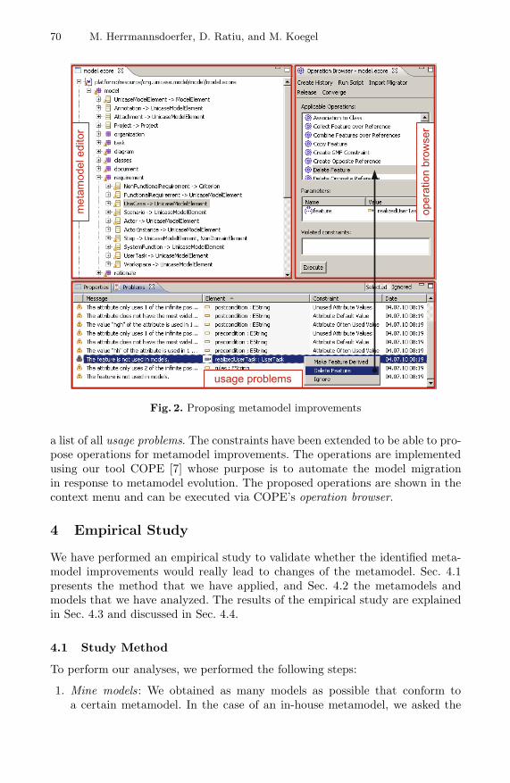
70 M. Herrmannsdoerfer, D. Ratiu, and M. Koegel
Fig. 2. Proposing metamodel improvements
a list of all usage problems. The constraints have been extended to be able to pro-pose operations for metamodel improvements. The operations are implementedusing our tool COPE [7] whose purpose is to automate the model migrationin response to metamodel evolution. The proposed operations are shown in thecontext menu and can be executed via COPE’s operation browser.
4 Empirical Study
We have performed an empirical study to validate whether the identified meta-model improvements would really lead to changes of the metamodel. Sec. 4.1presents the method that we have applied, and Sec. 4.2 the metamodels andmodels that we have analyzed. The results of the empirical study are explainedin Sec. 4.3 and discussed in Sec. 4.4.
4.1 Study Method
To perform our analyses, we performed the following steps:
1. Mine models: We obtained as many models as possible that conform toa certain metamodel. In the case of an in-house metamodel, we asked the

Metamodel Usage Analysis for Identifying Metamodel Improvements 71
metamodel developers to provide us with the models known to them. For thepublished metamodels, we iterated through several open repositories (CVSand SVN) and downloaded all models conforming to these metamodels. Asfar as possible, we removed duplicated models.
2. Perform usage analysis : We applied the approach presented in Sec. 3 on themined models. For each of the analyzed metamodels, this results in a set ofusage problems.
3. Interpret usage problems : To determine whether the usage problems reallyhelp us to identify possible metamodel improvements, we tried to find expla-nations for the problems. In order to do so, we investigated the documenta-tion of the metamodels as well as the interpreters of the modeling languages,and, if possible, we interviewed the metamodel developers.
4.2 Study Objects
Metamodels. To perform our experiments, we have chosen 7 metamodelswhose usage we have analyzed. Table 1 shows the number of elements of thesemetamodels. Two metamodels are part of the Eclipse Modeling Framework(EMF)1 which is used to develop the abstract syntax of a modeling language:The ecore metamodel defines the abstract syntax from which an API for modelaccess and a structural editor can be generated; and the genmodel allows to cus-tomize the code generation. Four metamodels are part of the Graphical ModelingFramework (GMF)2 which can be used to develop the diagrammatic, concretesyntax of a modeling language: the graphdef model defines the graphical elementslike nodes and edges in the diagram; the tooldef model defines the tools avail-able to author a diagram; the mappings model maps the nodes and edges fromthe graphdef model and the tools from the tooldef model onto the metamodelelements from the ecore model; and the mappings model is transformed into agmfgen model which can be altered to customize the generation of a diagrameditor. Finally, the last metamodel (unicase) is part of the tool UNICASE3 whichcan be used for UML modeling, project planning and change management.
Table 1. A quantitative overview over the analyzed metamodels
# ecore genmodel graphdef tooldef mappings gmfgen unicase
Class 20 14 72 26 36 137 77
Attribute 33 110 78 16 22 302 88
Reference 48 34 57 12 68 160 161
Models. For each metamodel, we have mined models from different repositories.Table 2 shows the repositories as well as the number of files and elements which
1 See EMF web site: http://www.eclipse.org/emf2 See GMF web site: http://www.eclipse.org/gmf3 See UNICASE web site: http://unicase.org

72 M. Herrmannsdoerfer, D. Ratiu, and M. Koegel
Table 2. A quantitative overview over the analyzed models
ecore genmodel graphdef tooldef mappings gmfgen
repository files elem.s files elem.s files elem.s files elem.s files elem.s files elem.s
AUTOSAR 18 384,685 18 16,189 11 1,835 11 436 11 538 13 2,373
Eclipse 1,834 250,107 818 69,361 105 6,026 58 1,769 72 5,040 52 11,043
GForge 106 26,736 94 41,997 12 806 10 241 11 480 11 1,680
Google 50 9,266 59 3,786 69 7,627 74 2,421 76 4,028 78 18,710
Atlantic Zoo 278 68,116 – – – – – – – – – –
altogether 2,286 738,910 989 131,333 197 16,294 153 4,867 170 10,086 154 33,806
have been obtained from them. Models that conform to the first 6 metamodelshave been obtained from the AUTOSAR development partnership4, from theEclipse5 and GForge6 open source repositories, by querying the Google CodeSearch7 and from the Atlantic Zoo8. The Atlantic Zoo only contains ecore models,while the other repositories contain models for all EMF and GMF metamodels.For the unicase metamodel, its developers provided us with 3 files consisting of8,213 model elements.
4.3 Study Results
In this section, we present the study results separately for each question men-tioned in Sec. 3.2. To facilitate understanding the explanations for the identifiedusage problems, we clustered them according to high-level explanations.
Q1) Which classes are not used? Table 3 quantitatively illustrates for eachmetamodel the number of used and not used classes in the overall number of non-abstract classes. The second last row shows the number of classes that are used,whereas the other rows classify the unused classes according to the explanationswhy they are not used. As presented in Sec. 4.1, we derived these explanations bymanually analyzing the documentation and implementation of the metamodelsor interviewing the developers.
Classes that are obsolete, not implemented, or that logically belong to anothermetamodel can be removed. A class is obsolete if it is not intended to be used inthe future. For example, in unicase, the 4 classes to define UML stereotypes areno longer required. A class is not implemented if it is not used by the interpretersof the modeling language. For example, the tooldef metamodel defines 7 classesto specify menus and toolbars from which, according to [4], currently no codecan be generated. A class should be moved to another metamodel if it logicallybelongs to the other metamodel. For example, in tooldef, the class GenericStyle-Selector should be moved to mappings which contains also a composite reference4 See AUTOSAR web site: http://www.autosar.org5 See Eclipse Repository web site: http://dev.eclipse.org/viewcvs/index.cgi6 See GForge web site: http://gforge.enseeiht.fr7 See Google Code Search web site: http://www.google.com/codesearch8 See Atlantic Zoo web site: http://www.emn.fr/z-info/atlanmod/index.php/Ecore

Metamodel Usage Analysis for Identifying Metamodel Improvements 73
Table 3. Usage of classes
Explanation ecore
genm
odel
graphdef
toold
ef
mappin
gs
gm
fgen
unic
ase
is obsolete 4
is not implemented 7 1
should be moved 1 2
should be abstract 1
should be transient 1 2 1
is too new 3 6 5
should be used 1 1 6 9
is used 13 11 51 11 24 83 42
altogether 15 11 55 19 25 97 64
Table 4. Usage of ecore classes
# Class Number Share
1 EStringToStringMapEntry 328,920 44.51%2 EGenericType 141,043 19.09%3 EAnnotation 102,863 13.92%4 EReference 53,177 7.20%5 EClass 41,506 5.62%6 EAttribute 36,357 4.92%7 EEnumLiteral 10,643 1.44%8 EOperation 7,158 0.97%9 EParameter 7,060 0.96%
10 EPackage 4,530 0.61%11 EDataType 2,747 0.37%12 EEnum 2,513 0.34%13 ETypeParameter 226 0.03%14 EObject 0 0.00%15 EFactory 0 0.00%
targeting this class. Another example is unicase where 2 classes should be movedto a different metamodel of another organization that also uses the frameworkunderlying UNICASE.
Our manual investigations revealed that other classes that are not used shouldbe abstract or transient. A class should be abstract if it is not intended to beinstantiated, and is used only to define common features inherited by its sub-classes. For instance, in ecore, EObject—the implicit common superclass of allclasses—should be made abstract. A class should be transient if its instances arenot expected to be made persistent—such a class does not represent a languageconstruct. However, the employed metamodeling formalism currently does notsupport to specify that a class is transient. For instance, in ecore, EFactory—ahelper class to create instances of the specified metamodel—should be transient.
Finally, there are non-used classes which do not require any change, sincethey are either too new or should be used—i. e. we could not find any plausibleexplanation why they are not used. A class is too new if it was recently addedand thus is not yet instantiated in models. For the GMF metamodels graphdefand gmfgen, we identified 9 new classes, while for the unicase metamodel, wefound 5 classes that are too new to be used.
Q2) What are the most widely used classes in ecore? Due to space con-straints, we focus on the ecore metamodel to answer this question. Table 4 showsits classes and their corresponding number of instances. Interestingly, the numberof instances of the ecore classes has an exponential distribution, a phaenomenonobserved also in case of the other metamodels. Hence, each metamodel containsa few constructs which are very central to its users. In the case of ecore, weexpect that classes, references and attributes are the central constructs. How-ever, the most widely used ecore class is—with more than 44,5% of the analyzedinstances—EStringToStringMapEntry which defines key-value-pairs for EAnnota-tions making up 13,9% of the instances. The fact that the annotation mechanismwhich is used to extend the ecore metamodel is more widely used than the first-class constructs, suggests the need for increasing ecore’s expressiveness. As weshow in Q7, some often encountered annotations could be lifted to first-class

74 M. Herrmannsdoerfer, D. Ratiu, and M. Koegel
Table 5. Usage of features
Explanation ecore
genm
odel
graphdef
toold
ef
mappin
gs
gm
fgen
unic
ase
is obsolete 9 11
is not implemented 3 2 2 5
should be moved 11
should be derived 2
is too new 6 16 6
should be used 1 7 2 55 13
is not confident 6 6 1 23 35
is used 51 125 118 20 84 333 163
altogether 52 135 132 28 87 441 241
Table 6. Usage of multiplicity by features
Explanation ecore
genm
odel
graphdef
toold
ef
mappin
gs
gm
fgen
unic
ase
should increase ←↩ 2 1 2 1 21 5the lower boundis not implemented 3 1should have a ←↩ 5 1 48 3derived defaultis too new 5 2should be used 5 4 4 12 3is not confident 6 6 1 23 35is used 52 123 115 17 80 337 193
altogether 52 135 132 28 87 441 241
constructs. Another ecore class that is used very often is EGenericType. Thisis surprising, since we would expect that generic types are very rarely used inmetamodels. The investigation of how this class is exactly used, revealed the factthat only 1,8% (2,476) of EGenericType’s instances do not define default valuesfor their features and thereby these instances really represent generic types. Inthe other 98%, the EGenericType is only used as an indirection to the non-generictype, i. e. in a degenerated manner.
Q3) Which features are not used? Table 5 shows for each metamodel thenumber of used and unused features in the overall number of non-derived fea-tures. In the table, we observe a correlation between the number of unusedfeatures and the overall number of features. In most cases, the more featuresa metamodel defines, the less features are actually used. The only exception tothis conjecture is the usage of the tooldef metamodel, in which most featuresare however not implemented as explained below. The table also classifies theunused features according to explanations why they are not used.
Features that are obsolete, not implemented, or logically belong to anothermetamodel can be removed from the metamodel. A feature is obsolete if it is notintended to be used in the future. If none of the analyzed models uses that fea-ture, it is a good candidate to be removed. We identified the 9 obsolete featuresof gmfgen by investigating the available migrator. Surprisingly, the migrator re-moves their values, but the developers forgot to remove the features from gmfgen.In the case of the unicase metamodel, 11 unused features are actually obsolete. Afeature is classified as not implemented if it is not used by the interpreters of themodeling language. We have identified 12 not implemented features of the EMFmetamodel genmodel and the GMF metamodels tooldef, mappings and gmfgenby checking whether they are accessed by the code generators. A feature shouldbe moved to another metamodel if it logically belongs to the other metamodel.The features of the unicase metamodel that have to be moved target the classesthat should be moved to another metamodel as found by question Q1 in Sec. 3.2.
Another set of non-used features can be changed into derived features, sincetheir values are calculated based on other features. As they are anyway over-written in the metamodel implementation, setting them explicitly is a mistake,

Metamodel Usage Analysis for Identifying Metamodel Improvements 75
making the language easy to misuse. For example, for the unicase metamodel,we identified 2 features that should be derived.
Finally, there are non-used features which do not require changes at all, sincethey are either too new or our investigation could not identify why the feature isnot used. Again, a feature is too new to be instantiated, if it was recently added.Like for classes, the 28 too new features were identified by investigating themetamodel histories. The only feature of the ecore metamodel which is not set inany model but should be used allows to define generic exceptions for operations.Apparently, exceptions rarely need to have type parameters defined or assigned.For both genmodel and gmfgen, more than 5% of the features should be used butare not used. The manual investigation revealed that these are customizationsof the code generation that are not used at all. We are not confident about theusage of a feature if there are no instances in which the feature could be set. Thiscategory thus indicates how many features cannot be used, because the classesin which they are defined are not instantiated.
Q4) Which features are not used to their full multiplicity? Table 6 showsas is used the number of used features fulfilling these expectations. Again, theviolations are classified according to different explanations that we derived aftermanual investigation of the metamodel documentation and implementation.
A not completely used feature which can be restricted either should increasethe lower bound or is not implemented yet. Even though we found features whoseusage did not completely use the upper bound, we could not find an explana-tion for any of them. However, we found that some features should increaselower bound from 0 to 1. For the EMF and GMF metamodels, we found suchfeatures by analyzing whether the code generator does not check whether thefeature is set, thereby producing an error if the feature is not set. For the uni-case metamodel, the too low lower bounds date back from the days when itsdevelopers used an object-to-relational mapping to store data. When doing so, alower bound of 1 was transformed into a database constraint which required toset the feature already when creating a model element. To avoid this restriction,the lower bounds were decreased to 0, when in effect, they should have been 1.As they no longer store the models in a database, the lower bounds could easilybe increased. Again, a feature is not implemented if the interpreter does not usethe feature. In the tooldef metamodel, we found 3 such features which are notinterpreted by the code generator, making them also superfluous.
A not completely used feature which requires to extend the metamodelingformalism should have a derived default. A feature should have a derived defaultif it has lower bound 0, but in case it is not set, a default value is derived.This technique is mostly used by the code generation metamodels genmodel andgmfgen to be able to customize a value which is otherwise derived from otherfeatures. It is implemented by overwriting the API to access the models whichis generated from the metamodel. However, the used metamodeling formalismdoes not provide a means to specify that a feature has a derived default.
A not completely used feature which does not require changes either is toonew or should be used.
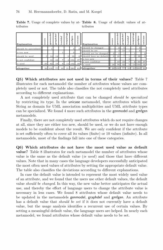
76 M. Herrmannsdoerfer, D. Ratiu, and M. Koegel
Table 7. Usage of complete values by at-tributes
Explanation ecore
genm
odel
graphdef
toold
ef
mappin
gs
gm
fgen
unic
ase
should be specialized 1 3 3
is too new 1 3
should be used 1 14 14 3 18 4
is not confident 12 44 7 4 164 37
is used 25 82 19 8 14 102 39
altogether 26 109 77 16 21 290 83
Table 8. Usage of default values of at-tributes
Explanation ecore
genm
odel
graphdef
toold
ef
mappin
gs
gm
fgen
unic
ase
should be changed 2 5 3should be set 4 13 1 6should not be changed 2 1 1 1 2should have no default 6 16 7 1 3 38 9is too new 2is not confident 10 19 7 4 93 37is used 18 76 32 5 13 150 35
altogether 26 109 77 16 21 290 83
Q5) Which attributes are not used in terms of their values? Table 7illustrates for each metamodel the number of attributes whose values are com-pletely used or not. The table also classifies the not completely used attributesaccording to different explanations.
A not completely used attribute that can be changed should be specializedby restricting its type. In the unicase metamodel, three attributes which useString as domain for UML association multiplicities and UML attribute typescan be specialized. We found 4 more such attributes in the genmodel and gmfgenmetamodels.
Finally, there are not completely used attributes which do not require changesat all, since they are either too new, should be used, or we do not have enoughmodels to be confident about the result. We are only confident if the attributeis set sufficiently often to cover all its values (finite) or 10 values (infinite). In allmetamodels, most of the findings fall into one of these categories.
Q6) Which attributes do not have the most used value as defaultvalue? Table 8 illustrates for each metamodel the number of attributes whosevalue is the same as the default value (is used) and those that have differentvalues. Note that in many cases the language developers successfully anticipatedthe most often used values of attributes by setting the appropriate default value.The table also classifies the deviations according to different explanations.
In case the default value is intended to represent the most widely used valueof an attribute, and we found that the users use other default values, the defaultvalue should be changed. In this way, the new value better anticipates the actualuse, and thereby the effort of language users to change the attribute value isnecessary in less cases. We found 8 attributes whose default value needs tobe updated in the metamodels genmodel, graphdef and gmfgen. An attributehas a default value that should be set if it does not currently have a defaultvalue, but the usage analysis identifies a recurrent use of certain values. Bysetting a meaningful default value, the language users are helped. In nearly eachmetamodel, we found attributes whose default value needs to be set.
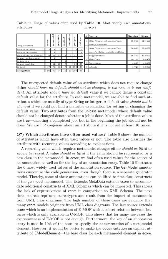
Metamodel Usage Analysis for Identifying Metamodel Improvements 77
Table 9. Usage of values often used byattributes
Explanation ecore
genm
odel
graphdef
toold
ef
mappin
gs
gm
fgen
unic
ase
should be lifted 3 1 3 3 2should be reused 1 4should not be changed 6 18 22 1 3 41 3is not implemented 1is too new 1is not confident 11 19 7 93 37is used 17 77 33 7 18 153 37
altogether 26 109 77 16 21 290 83
Table 10. Most widely used annotationsin ecore
# Source Number Share
1 http://www.eclipse.org/emf/←↩ 33,056 32.15%
2002/GenModel
2 http:///org/eclipse/emf/←↩ 26,039 25.32%
ecore/util/ExtendedMetaData
3 TaggedValues 16,304 15.86%
4 MetaData 10,169 9.89%
5 Stereotype 4,628 4.50%
6 subsets 1,724 1.68%
...
The unexpected default value of an attribute which does not require changeeither should have no default, should not be changed, is too new or is not confi-dent. An attribute should have no default value if we cannot define a constantdefault value for the attribute. In each metamodel, we are able to find such at-tributes which are usually of type String or Integer. A default value should not bechanged if we could not find a plausible explanation for setting or changing thedefault value. Two attributes from the unicase metamodel whose default valueshould not be changed denote whether a job is done. Most of the attribute valuesare true—denoting a completed job, but in the beginning the job should not bedone. We are not confident about an attribute if it is not set at least 10 times.
Q7) Which attributes have often used values? Table 9 shows the numberof attributes which have often used values or not. The table also classifies theattribute with recurring values according to explanations.
A recurring value which requires metamodel changes either should be lifted orshould be reused. A value should be lifted if the value should be represented by anew class in the metamodel. In ecore, we find often used values for the source ofan annotation as well as for the key of an annotation entry. Table 10 illustratesthe 6 most widely used values of the annotation source. The GenModel annota-tions customize the code generation, even though there is a separate generatormodel. Thereby, some of these annotations can be lifted to first-class constructsof the genmodel metamodel. The ExtendedMetaData extends ecore to accommo-date additional constructs of XML Schemas which can be imported. This showsthe lack of expressiveness of ecore in comparison to XML Schema. The nextthree sources represent stereotypes and result from the import of metamodelsfrom UML class diagrams. The high number of these cases are evidence thatmany ecore models originate from UML class diagrams. The last source extendsecore which is an implementation of E-MOF with a subset relation between fea-tures which is only available in C-MOF. This shows that for many use cases theexpressiveness of E-MOF is not enough. Furthermore, the key of an annotationentry is used in 10% of the cases to specify the documentation of a metamodelelement. However, it would be better to make the documentation an explicit at-tribute of EModelElement—the base class for each metamodel element in ecore.

78 M. Herrmannsdoerfer, D. Ratiu, and M. Koegel
A value should be reused if—instead of recurrently using the value—we refer toa single definition of the value as instance of a new class. In unicase, instead ofdefining types of UML attributes as Strings, it would be better to group theminto separate instances of reusable data types.
An attribute with recurring values which does not require change either shouldnot be changed, is not implemented, is too new or we are not confident. For a lotof attributes, we have not found a plausible explanation, and thus conservativelyassumed that they should not be changed.
4.4 Discussion
Lessons learned. Based on the results of our analyses, we learned a numberof lessons about the usage of metamodels by existing models.
Metamodels can be more restrictive. In all investigated cases, the set of modelscovers only a subset of the set of all possible models that can be built witha metamodel. We discovered that not all classes are instantiated (Q1), not allfeatures are used (Q3), and the range of the cardinality of many features doesnot reflect their definition from the metamodel (Q4). In all these cases, themetamodels can be improved by restricting the number of admissible models.
Metamodels can contain latent defects. During our experiments, we discoveredin several cases defects of the metamodels—e. g. classes that should not be in-stantiated and are not declared abstract (Q1), classes and features that are notimplemented or that are overwritten by the generator (Q1, Q3, Q4, Q6). More-over, in other cases (Q2), we discovered misuses of metamodel constructs.
Metamodels can be extended. Each of the analyzed metamodels offers their usersthe possibility to add new information (e. g. as annotations, or sets of key-valuepairs). The analysis of the manners in which the metamodels are actually ex-tended reveal that the users recurrently used several annotation patterns. Thesepatterns reveal the need to extend the metamodel with new explicit constructsthat capture their intended use (Q2, Q7). Moreover, the specification of someattributes can be extended with the definition of default values (Q6).
Metamodeling formalism can be improved. Our metamodeling formalism is verysimilar to ecore. The results indicate that in certain cases the metamodelingformalism is not expressive enough to capture certain constraints. For instance,we would have required to mark a class as transient (Q1) and to state that afeature has a default value derived from other features (Q4). Consequently, wehave also identified improvements concerning the metamodeling formalism.
Limitations. We are aware of the following limitations concerning our results.
Validity of explanations. We presented a set of explanations for the deviationsbetween expectation and usage. In the case of UNICASE, we had direct access tothe language developers and hence could ask them directly about their explana-tions for the usage problems. In the case of the other metamodels, we interpreted

Metamodel Usage Analysis for Identifying Metamodel Improvements 79
the analysis results based only on the documentation and implementation. Con-sequently, some of our explanations can be mistaken.
Relevance and number of analyzed models. We analyzed only a subset of theentire number of existing models. This fact can make our results rather ques-tionable. In the case of UNICASE, we asked the developers to provide us with arepresentative sample of existing models. In the case of the other metamodels,we mined as many models as possible from both public and private (AUTOSAR)repositories to obtain a representative sample of existing models.
5 Related Work
Investigating language utterances. In the case of general-purpose languages,investigating their use is especially demanding, as a huge number of programs ex-ist. There are some landmark works that investigate the use of general-purposelanguages [3,17,11]. Gil et al. present a catalog of Java micro patterns whichcapture common programming practice on the class-level [3]. By automaticallysearching these patterns in a number of projects, they show that 75% of theclasses are modeled after these patterns. Singer et al. present a catalog of Javanano patterns which capture common programming practice on the method-level [17]. There is also work on investigating the usage of domain-specific lan-guages. Lammel et al. analyze the usage of XML schemas by applying a numberof metrics to a large corpus [10]. Lammel and Pek present their experience withanalyzing the usage of the W3C’s P3P language [11]. Our empirical results—thatmany language constructs are more often used than others—are consistent withall these results. We use a similar method for investigating the language utter-ances, but our work is focused more on identifying improvements for languages.Tolvanen proposes a similar approach for the metamodeling formalism providedby MetaCase [19]. However, even if the sets of analyses are overlapping, our setcontains analyses not addressed by Tolvanen’s approach (Q2, Q5 and Q7), andprovides a validation through a large-scale empirical study that usage analysesdo help to identify metamodel improvements.
Language improvements. Once the information about the language use isavailable, it can serve for language improvements. Atkinson and Kuehne presenttechniques for language improvements like restricting the language to the usedsubset or adding new constructs that reflect directly the needs of the languageusers [1]. Sen et al. present an algorithm that prunes a metamodel [16]: it takesa metamodel as input as well as a subset of its classes and features, and out-puts a restricted metamodel that contains only the desired classes and features.By doing this, we obtain a restricted metamodel that contains only necessaryconstructs. Our work on mining the metamodel usage can serve as input forthe pruning algorithm that would generate a language more appropriate to theexpectations of its users. Once recurrent patterns are identified, they can serve
80 M. Herrmannsdoerfer, D. Ratiu, and M. Koegel
as source for new language constructs [2]. The results in this paper demon-strate that the analysis of built programs is a feasible way to identify languageimprovements. Lange et al. show—by performing an experiment—that mod-eling conventions have a positive impact on the quality of UML models [12].Henderson-Sellers and Gonzalez-Perez report on different uses and misuses ofthe stereotype mechanism provided by UML [6]. By analyzing the built models,we might be able to identify certain types of conventions as well as misuses oflanguage extension mechanisms.
Tool usage. There is work on analyzing the language use by recording andanalyzing the interactions with the language interpreter. Li et al. [13] present astudy on the usage of the Alloy analyzer tool. From the way how the analyzertool was used, they identified a number of techniques to improve analysis per-formance. Hage and Keeken [5] present the framework Neon to analyze usage ofa programming environment. Neon records data about every compile performedby a programmer and provides a query to analyze the data. To evaluate Neon,the authors executed analyses showing how student programmers improve overtime in using the language. The purpose of our approach is not to improve thetools for using the language, but to improve the language itself.
6 Conclusions and Future Work
This paper is part of a more general research direction that we investigate,namely how to analyze the use of modeling languages in order to assess theirquality. The focus of this paper is to derive possible improvements of the meta-model by analyzing the language use. We are convinced that the analysis ofmodels built with a modeling language is interesting for any language developer.We showed that—even in the case of mature languages—the analysis of modelscan reveal issues with the modeling language. Due to the promising results, weplan to further improve the approach presented in this paper. First, we intend torefine the presented analyses by fine-tuning them according to the results fromthe empirical study. Second, we plan to add new analyses which are currentlymissing in the catalog. Third, we intend to apply the presented approach as partof a method for the evolutionary development of modeling languages.
For languages used by different organizations, the analysis of models is oftenimpossible due to the intellectual property that the models carry. We envisionas a future direction of research the definition of techniques that anonymize thecontent of the model and send the language developers only a limited informationneeded for analyzing the language use.
Acknowledgments. This work was partly funded by the German Federal Min-istry of Education and Research (BMBF), grants “SPES2020, 01IS08045A” and“Quamoco, 01IS08023B”.

Metamodel Usage Analysis for Identifying Metamodel Improvements 81
References
1. Atkinson, C., Kuhne, T.: A tour of language customization concepts. Advances inComputers 70, 105–161 (2007)
2. Bosch, J.: Design patterns as language constructs. JOOP - Journal of Object-Oriented Programming 11(2), 18–32 (1998)
3. Gil, J., Maman, I.: Micro patterns in Java code. In: OOPSLA 2005: Conference onObject-Oriented Programming, Systems, Languages, and Applications, pp. 97–116.ACM, New York (2005)
4. Gronback, R.C.: Eclipse Modeling Project: A Domain-Specific Language (DSL)Toolkit. Addison-Wesley, Reading (2009)
5. Hage, J., van Keeken, P.: Neon: A library for language usage analysis. In: Gasevic,D., Lammel, R., Van Wyk, E. (eds.) SLE 2008. LNCS, vol. 5452, pp. 35–53.Springer, Heidelberg (2009)
6. Henderson-Sellers, B., Gonzalez-Perez, C.: Uses and abuses of the stereotype mech-anism in UML 1.x and 2.0. In: Wang, J., Whittle, J., Harel, D., Reggio, G. (eds.)MoDELS 2006. LNCS, vol. 4199, pp. 16–26. Springer, Heidelberg (2006)
7. Herrmannsdoerfer, M., Benz, S., Juergens, E.: COPE - automating coupled evolu-tion of metamodels and models. In: Drossopoulou, S. (ed.) ECOOP 2009. LNCS,vol. 5653, pp. 52–76. Springer, Heidelberg (2009)
8. Karsai, G., Krahn, H., Pinkernell, C., Rumpe, B., Schindler, M., Volkl, S.: De-sign guidelines for domain specific languages. In: The 9th OOPSLA Workshop onDomain-Specific Modeling (2009)
9. Kelly, S., Pohjonen, R.: Worst practices for domain-specific modeling. IEEE Soft-ware 26(4), 22–29 (2009)
10. Lammel, R., Kitsis, S., Remy, D.: Analysis of XML schema usage. In: ConferenceProceedings XML 2005 (November 2005)
11. Lammel, R., Pek, E.: Vivisection of a non-executable, domain-specific language;understanding (the usage of) the P3P language. In: ICPC 2010: 18th InternationalConference on Program Comprehension. IEEE, Los Alamitos (2010)
12. Lange, C.F.J., DuBois, B., Chaudron, M.R.V., Demeyer, S.: An experimental inves-tigation of UML modeling conventions. In: Wang, J., Whittle, J., Harel, D., Reggio,G. (eds.) MoDELS 2006. LNCS, vol. 4199, pp. 27–41. Springer, Heidelberg (2006)
13. Li, X., Shannon, D., Walker, J., Khurshid, S., Marinov, D.: Analyzing the uses of asoftware modeling tool. In: LDTA 2006: 6th Workshop on Language Descriptions,Tools, and Applications, pp. 3–18. Elsevier, Amsterdam (2006)
14. Object Management Group: Meta Object Facility (MOF) core specification version2.0 (2006), http://www.omg.org/spec/MOF/2.0/
15. Paige, R.F., Ostroff, J.S., Brooke, P.J.: Principles for modeling language design.Information and Software Technology 42(10), 665–675 (2000)
16. Sen, S., Moha, N., Baudry, B., Jezequel, J.-M.: Meta-model pruning. In: Schurr, A.,Selic, B. (eds.) MODELS 2009. LNCS, vol. 5795, pp. 32–46. Springer, Heidelberg(2009)
17. Singer, J., Brown, G., Lujan, M., Pocock, A., Yiapanis, P.: Fundamental nano-patterns to characterize and classify java methods. In: LDTA 2009: 9th Workshopon Language Descriptions, Tools and Applications, pp. 204–218 (2009)
18. Steinberg, D., Budinsky, F., Paternostro, M., Merks, E.: EMF: Eclipse ModelingFramework 2.0. Addison-Wesley, Reading (2009)
19. Tolvanen, J.P.: Incremental Method Engineering with Modeling Tools: TheoreticalPrinciples and Empirical Evidence. Ph.D. thesis, University of Jyvaskyla (1998)
20. Wachsmuth, G.: Metamodel adaptation and model co-adaptation. In: Bateni, M.(ed.) ECOOP 2007. LNCS, vol. 4609, pp. 600–624. Springer, Heidelberg (2007)

Domain-Specific Modelling Languageswith Algebraic Graph Transformations on RDF
Benjamin Braatz and Christoph Brandt
SECAN-Lab, Université du [email protected], [email protected]
http://wiki.uni.lu/secan-lab/
Abstract. Domain-specific modelling langugages (DSMLs), which aretailored to the requirements of their users, can significantly increase theacceptance of formal (or at least semi-formal) modelling in scenarioswhere informal drawings and natural language descriptions are predomi-nant today. We show in this paper how the Resource Description Frame-work (RDF), which is a standard for the fundamental data structures ofthe Semantic Web, and algebraic graph transformations on these datastructures can be used to realise the abstract syntax of such DSMLs.We examine a small DSML for IT infrastructures as an application sce-nario. From this scenario, we derive distributed modelling, evolution oflanguage definitions, migration of legacy models and integration of mod-elling languages as key requirements for a DSML framework. RDF andtransformation rules are then used to provide a solution, which meetsthese requirements, where all kinds of modifications—from simple edit-ing steps via model migration to language integration—are realised bythe single, uniform formalism of algebraic graph transformation.
1 Introduction
Our motivation for the work presented in this paper is to obtain a frameworkfor the definition and management of families of domain-specific modelling lan-guages (DSMLs). We use the term DSMLs to denote small, flexible, visual andtextual languages that are tailored to the needs of their users in a certain ap-plication domain. Such languages typically cannot be defined once and for all,but they are in a constant state of flux, since requirements of the stakehold-ers may become apparent or new requirements may emerge during the life-timeof the language. Moreover, the framework should allow families of integratedDSMLs, i. e., several DSMLs—each created for a specific task or a specific groupof users—are synchronised on their common overlapping aspects.
In Sect. 2, we present an application scenario for DSMLs, from which wederive seven guiding problems for our framework, where key requirements areevolution and integration of DSMLs.
We use the Resource Decription Framework (RDF), defined in [1], for rep-resenting the abstract syntax of DSMLs. This representation is introduced inSect. 3. RDF is used as the fundamental, generic data structure for the Seman-tic Web. It is, therefore, well-suited for the distributed management of models
B. Malloy, S. Staab, and M. van den Brand (Eds.): SLE 2010, LNCS 6563, pp. 82–101, 2011.c© Springer-Verlag Berlin Heidelberg 2011

DSMLs with Algebraic Graph Transformations on RDF 83
in large organisations. With this choice, we expect to reduce the effort that isrequired for the creation of large integrated models from the knowledge of localusers, while also allowing decentralised workflows.
In Sect. 4, we introduce algebraic graph transformations on RDF graphs.Algebraic graph transformations for RDF were proposed and developed in [2,3].They are used in this paper to provide a single, uniform formalism for all kindsof modifications on models—editing, migration and integration. One of its keyadvantages is that it can be fully implemented.
In Sect. 5, we show how DSMLs can evolve in our framework and how graphtransformations can be used to achieve the migration of models according tosuch a evolution. In Sect. 6, we present the integration of the languages from theapplication scenario, again using graph transformations.
Finally, we give comparisons to related work in Sect. 7 and some concludingremarks in Sect. 8.
2 Application Scenario: IT Infrastructure DSML
In this section, we present an application scenario for our proposed DSML frame-work. It is concerned with a DSML for IT infrastructures, as it may be used bythe experts in the field. The language is rather small and simple, but a similarlanguage for the real world would in principle work on the same level of abstrac-tion, tailored to the needs of the users and resembling the informal languagesthey use today.
In Fig. 1, we see a model of an IT landscape and some editing steps modifyingthis model. The model shows some local area networks (LANs), the Internet asa wide area network (WAN) and the connections between them, where some ofthem are protected by firewalls. The local network LAN 1 is connected to theInternet only through a demilitarised zone (DMZ), where both connections areprotected. During the editing steps a local network for backup systems is intro-duced, which is supposed to be reachable through two unprotected connections,which are also added.
Our first problem arises from the requirement that we want to replace themodels that are today created by single stakeholders or small teams with inte-grated models that are created by all relevant stakeholders together in order toprovide a common ground for communication.
Problem 1 (Distributed Management of Models). We want to be able to managethe models in a distributed system, such that all stakeholders can work on (partsof) the same model in parallel.
The next two problems are motivated by the requirement that, instead of justusing informal drawings, we want to provide techniques for modelling languageswith an abstract syntax that is precisely and formally defined.
Problem 2 (Definition of DSMLs). We need a technique to define the language,i. e., which types of language element exist and which configurations of theseelements constitute legal models.
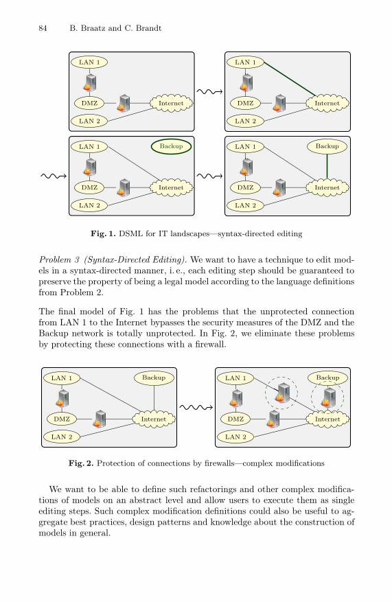
84 B. Braatz and C. Brandt
LAN 1
DMZ
LAN 2
Internet
LAN 1
DMZ
LAN 2
Internet
LAN 1
DMZ
LAN 2
Internet
Backup LAN 1
DMZ
LAN 2
Internet
Backup
Fig. 1. DSML for IT landscapes—syntax-directed editing
Problem 3 (Syntax-Directed Editing). We want to have a technique to edit mod-els in a syntax-directed manner, i. e., each editing step should be guaranteed topreserve the property of being a legal model according to the language definitionsfrom Problem 2.
The final model of Fig. 1 has the problems that the unprotected connectionfrom LAN 1 to the Internet bypasses the security measures of the DMZ and theBackup network is totally unprotected. In Fig. 2, we eliminate these problemsby protecting these connections with a firewall.
LAN 1
DMZ
LAN 2
Internet
Backup LAN 1
DMZ
LAN 2
Internet
Backup
Fig. 2. Protection of connections by firewalls—complex modifications
We want to be able to define such refactorings and other complex modifica-tions of models on an abstract level and allow users to execute them as singleediting steps. Such complex modification definitions could also be useful to ag-gregate best practices, design patterns and knowledge about the construction ofmodels in general.

DSMLs with Algebraic Graph Transformations on RDF 85
Problem 4 (Complex Modifications of Models). It should be possible to abstract-ly define complex modifications and easily instantiate and execute them inconcrete situations. The modifications should guarantee to respect the languagedefinitions from Problem 2.
DSMLs change frequently. For example, we could introduce a distinction betweenpublic and restricted LANs to our example DSML. This allows to document andvisualise the reason why the networks LAN 1 and Backup are protected, butLAN 2 is allowed to have an unprotected connection to the Internet. This isdone in Fig. 3, where restricted LANs are visualised by double borders, whilethe public LAN 2 is shown with a dashed double border.
LAN 1
DMZ
LAN 2
Internet
Backup LAN 1
DMZ
LAN 2
Internet
Backup
Fig. 3. Public LANs and restricted LANs—language evolution and model migration
The requirement of allowing language evolution leads to two problems—theevolution to a new language definition itself and the migration of legacy modelsaccording to the old definition.
Problem 5 (Evolution of DSMLs). It should be possible with minimal effort toadapt a language according to needs of users.
Problem 6 (Migration of Models). We need a technique to migrate legacy modelsfrom a previous language defintion to the evolved definition.
If we have several DSMLs that overlap in certain aspects then we want to beable to integrate them. In Fig. 4, we see an example in our application scenario,where the landscape is enhanced with a notation for the protocols allowed bythe firewalls and a second (textual) DSML for the configurations of firewalls isintroduced. The integration consists of identifying which configuration snippetsbelong to which firewall in the landscape and removing and adding configura-tion lines and protocols in the landscape diagram, such that they match eachother.
Problem 7 (Integration of DSMLs). We want to have a technique to integratemultiple DSMLs that overlap in certain aspects.

86 B. Braatz and C. Brandt
fw1.example.comFROM if1 TO if2
PORT 5432 ALLOW;FROM if2 TO if1
PORT 80 ALLOW;
fw2.example.comFROM if1 TO if2
PORT 80 ALLOW;
fw3.example.comFROM if2 TO if1
PORT 22 ALLOW;FROM if2 TO if1
PORT 53 ALLOW;
fw4.example.comFROM if1 TO if2
PORT 22 ALLOW;FROM if2 TO if1
PORT 22 ALLOW;
LAN 1
DMZ
LAN 2
Internet
Backup
http
http
http
ssh
ssh
fw1.example.comFROM if1 TO if2
PORT 5432 ALLOW;FROM if2 TO if1
PORT 80 ALLOW;
fw2.example.comFROM if1 TO if2
PORT 80 ALLOW;FROM if2 TO if1
PORT 80 ALLOW;
LAN 1
DMZ
LAN 2
Internet
Backup
if2
if1
if2if1
if2
if1
if2
if1
httpdb
http
http
ssh, dns
ssh
fw3.example.comFROM if2 TO if1
PORT 22 ALLOW;FROM if2 TO if1
PORT 53 ALLOW;
fw4.example.comFROM if1 TO if2
PORT 22 ALLOW;
Fig. 4. IT landscape and firewall configurations—language integration
3 RDF Graphs: Abstract Syntax for DSMLs
The Resource Description Framework (RDF), defined in [1], provides the funda-mental data structures for the Semantic Web. It is used to state facts about re-sources that are either identified by Uniform Resource Identifiers (URIs) or givendirectly as literal values. The facts are given by subject–predicate–object triples,where the predicate is also given by a URI. A set of facts is an RDF graph, wherethe subjects and objects are the nodes and the facts the edges of the graph, la-belled with the corresponding predicate (which may also appear as a node). Theidea is that everyone can publish such graphs to assert certain facts and thesegraphs can easily be joined to collect information from heterogeneous sources.
In Fig. 5, we show how such a graph is used to represent part of an IT land-scape model. The local net LAN 1 and the Internet are represented by URIs“mod:LAN1” and “mod:INet”, respectively, where “mod:” is a suitable names-pace, e. g., “http://models.example.com/”. The names of the networks, whichare shown as inscriptions in the concrete visual representation, are given byliteral values. The predicate “rdf:type” (abbreviated as “a”) is used to connectnodes with their types. The types as well as the predicates are defined in anothernamespace “itml:”, which, e. g., might be “http://schema.example.com/”. Tech-nically, it would be possible to use the same namespace for both, the languageelements and the model instances, but seperation of namespaces eases the dis-tributed handling of schemas and (multiple) models by different groups of users.The connection between LAN 1 and the Internet is represented by a blank node

DSMLs with Algebraic Graph Transformations on RDF 87
ConcreteSyntax LAN 1 Internet
AbstractSyntax
itml:LAN itml:Connect itml:WAN
mod:LAN1 1 mod:INet
“LAN 1” “Internet”a = rdf:type
a a aitml:conn itml:conn
itml:name itml:name
Fig. 5. RDF graph representing the abstract syntax of a DSML model
“1”. Blank nodes do not have a global identity and, hence, other graphs cannotstate additional facts about entities identified by blank nodes.
The following formal definition of an RDF graph closely corresponds to theone given in [1]. The main difference is that we incorporate a set of blank nodesinto the graph, since they are supposed to be local to the corresponding graph.On the other hand, the sets of possible URIs and literals are globally givenand occurrences in different graphs are meant to identify the same entity. Animplementation should resemble this formal definition and allow arbitrary URIsand literals, while it may internally manage a cache of URIs and literals that arecurrently used.
Definition 1 (RDF Graph). An RDF graph G = (GBl, GTr) consists of a setGBl of blank nodes and a set GTr ⊆ GNd × URI × GNd of triples (also calledstatements or edges), where GNd := URI+Lit+GBl is the derived set of nodesof the graph and URI and Lit are globally given sets of all possible UniformResource Identifiers (URIs) and literals.1 The constituents s ∈ GNd, p ∈ URIand o ∈ GNd of a triple (s, p, o) ∈ GTr are called subject, predicate and object,respectively.
Solution 1 (Distribution of RDF Graphs). The use of RDF provides a solutionof Problem 1 of Sect. 2, since RDF is designed for the Semantic Web and, hence,provides excellent features for managing and relating distributed models. Morespecifically, the use of URIs as nodes enables us to distribute the creation oflanguage definitions and the maintenance of models, where the use of URIs andnamespaces facilitates seperation of concerns, while still allowing to relate themodels and language definitions through the use of URI references.
In RDF, vocabularies are used to define types that are supposed to be used asobjects of rdf:type triples. The vocabulary for our IT landscape language is givenin Fig. 6, where we also include visualisation hints in the vis: namespace in order1 The operations × and + denote the cartesian product and the disjoint union of sets,
respectively, where the disjointness ensures that we can determine if an element ofGNd is a URI, a literal or a blank node.

88 B. Braatz and C. Brandt
to allow the creation of generic visual clients. Vocabularies may also be calledschemas or ontologies, where we choose the term vocabulary, since it is the mostneutral one. In contrast to a meta model, a vocabulary has no possibilities toconstrain the structure of instances.
In [4], RDFS is introduced – a vocabulary for describing vocabularies. We usesome of the terms from RDFS, namely rdfs:subClassOf to define type hierarchiesand rdfs:domain and rdfs:range to define the domain and range of properties.RDFS is supposed to be used together with tools that can draw inferences fromthese information, e. g., adding additional super-types to an element or the do-main of a property to an element that is the subject of a corresponding triple, butwe do not rely on this in this paper and just use the RDFS terms descriptively.
The Web Ontology Language (OWL 2), defined in [5], introduces possibilitiesfor constraints, similar to the ones used in meta modelling. With these, structurescan not only be inferred, but also forbidden in order to meet the requirementsof a schema. In our approach, we will, however, not use OWL 2, but grammarsbased on graph transformation rules, which are introduced in the next section.
itml:Connectable itml:conn itml:Connect
vis:Glue vis:Line
itml:Appliance itml:Net itml:name
vis:RngInsideDomitml:FW itml:LAN itml:WAN
http://. . . /fw.png vis:Ellipse vis:Cloudsc = rdfs:subClassOf
sc sc
sc sc sc
rdfs:range rdfs:domain
rdfs:domain
vis:byPlace vis:byFig
vis:byPlace
vis:byIcon vis:byFig vis:byFig
Fig. 6. Vocabulary for IT landscapes with visualisation hints
Compared to the definition of languages by meta modelling, e. g., using theMeta Object Facility (MOF), defined in [6], the approach chosen here is very leanand light-weight. RDF graphs are supposed to be defined in a distributed manneron the Semantic Web with the help of heterogeneous vocabularies. In contrast tothat, MOF enforces that every model strictly conforms to a meta model, which,therefore, has to anticipate all needs of the users. Thus, the features of RDFideally reflect the flexibility requirements of DSMLs.
In [7], proposals for a mapping from MOF to RDF are requested. Such amapping would allow the representation of MOF meta models and correspondingmodels as RDF graphs and, hence, facilitate the application of the methodsintroduced in the present paper to MOF meta models and models.

DSMLs with Algebraic Graph Transformations on RDF 89
4 RDF Graph Transformation: Grammars and Editing
We use rule-based, algebraic graph transformations to describe all kinds ofchanges on RDF graphs. A comprehensive overview over the theory of alge-braic graph transformation can be found in [8]. The adaption of this theory toRDF was proposed in [2] and continued in [3].
We choose algebraic graph transformation, since it allows to treat all kindsof transformations from language definition by grammars via model migrationto language integration with a single, uniform formalism. Being a formal tech-nique, it also allows to reason formally about the effects of transformations toshow, e. g., that certain derived transformation rules respect a given grammar orthat transformations are independent of each other and can, hence, be swappedwithout affecting the result of the combined transformation.
Transformations are defined by transformation rules. An example of such arule is shown in Fig. 7. This rule removes a connection between two networks,represented by variables x and y and adds a new connection from network x tonetwork z, where z is not allowed to be of type itml:WAN and it is not allowedto introduce a self connection, i. e., to assign x and z to the same net.
L
α y
x itml:Connectz
itml:co
nnitml:conn
al
I
y
x itml:Connect
z
r
R
yx itml:Connect
β z
itml:connitml:conn
a
c1
N1
α y
x itml:Connect
itml:WAN z
itml:co
nnitml:conn
a
a
c2
N2
α yx,z
itml:Connect
itml:conn itml:conn
a
α
{del}y
x itml:Connect
β
{add}
z
itml:co
nn
{del}
itml:conn
{del}a {del}
a {add}
itml:conn{add} itml:conn
{add}
NACs:
itml:WAN
z
a
x,z
retargetConnection
Formal Structure Compact Notation
Fig. 7. Example transformation rule retargetConnection
The rule consists of several RDF patterns, which are graphs with additionalvariables, and RDF pattern homomorphisms, which are structure preservingmaps connecting the patterns, where the homomorphisms l and r are injective,i. e., one-to-one (visualised by the hook at the tail of the arrows). The differencebetween the left-hand side L and the interface I are the elements of the patternthat are supposed to be deleted and the difference between I and the right-handside R are the elements that are supposed to be added by the rule. Moreover,

90 B. Braatz and C. Brandt
there is a set of negative application conditions (NACs), which are extensions ofL and specify situations in which the rule is not applicable, where the NACs arein an implicit conjunction, i. e., all have to be satisfied and none of the situationsis allowed. In the lower right, we show a compact notation for the rule, whereirrelevant parts of the NACs are omitted and L, I and R are shown in a singlediagram with the additional elements of L marked by “{del}” and the additionalelements of R by “{add}”.
We now give the formal definition for RDF patterns and RDF pattern homo-morphisms. Observe that there are two different kinds of variables, one that canbe assigned to URIs, literals and blank nodes and one that can only be assignedto URIs, where only the latter kind can be used as predicates of triples. This isnecessary, because otherwise we would have to deal with inconsistencies due tovariables being on the one hand assigned to literals or blanks and on the otherhand used as predicates.
Definition 2 (RDF Pattern and RDF Pattern Homomorphism). AnRDF pattern P = (PBl, PV, PU, PTr) consists of a set PBl of blank nodes, a setPV of variables, a set PU ⊆ PV of URI variables and a set PTr ⊆ PNd× (URI+PU) × PNd of triples, where PNd := URI + Lit + PBl + PV is the derived set ofnodes.
An RDF pattern homomorphism h: P → Q between RDF patterns P andQ consists of a blank node function hBl: PBl → QBl and a variable assignmenthV:PV → QNd, such that hV(PU) ⊆ URI + QU and hTr(PTr) ⊆ QTr, wherehTr is the derived translation of triples given by the composed functions hTr :=hNd × (idURI + hV)× hNd and hNd := idURI + idLit + hBl + hV.2
We can now formally define transformation rules. The difference between blanknodes and variables is that blank nodes can be deleted and added by the rule,while the variable sets are required to stay the same during the whole transforma-tion. This is required for theoretical reasons, since variables may be instantiatedto URIs and literals, which are globally given and, hence, cannot be deleted oradded.
Definition 3 (Transformation Rule). A transformation rule tr = (L, I, R,l, r,NAC ) consists of RDF patterns L, I and R, called left-hand side, interfaceand right-hand side, respectively, RDF pattern homomorphisms l: I → L andr: I → R, where the blank node functions lBl and rBl are injective (one-to-one)and the variable assignments lV and rV are injective with lV(IV) = LV, rV(IV) =RV, lV(IU) = LU and rV(IU) = RU, i. e., the variable sets remain essentially thesame, and a set NAC of negative application conditions (NACs) (N, c) ∈ NAC ,where N is an RDF pattern and c:L→ N is an RDF pattern homomorphism.
In Fig. 8, we show the application of the transformation rule from Fig. 7 to anexample graph. The application is determined by a match homomorphism mfrom the left-hand side L to the graph G.2 We use the symbols × and + also for functions, where they denote the obvious
generalisations from operations on sets to operations on functions between corre-spondingly created sets. Moreover, idS denotes the identity function on a set S.

DSMLs with Algebraic Graph Transformations on RDF 91
L
α y
x itml:Connectz
itml:co
nnitml:conn
al
I
y
x itml:Connect
z
r
R
yx itml:Connect
β z
itml:connitml:conn
a
m (MPOC) i (PO) n
G
itml:LAN
itml:Connect
itml:WAN
mod:Net1
“Net 1”
1
mod:Net2
mod:Net3
itml:LAN
f
D
itml:LAN
itml:Connect
itml:WAN
mod:Net1
“Net 1”
mod:Net2
mod:Net3
itml:LAN
g
H
itml:LAN
itml:Connect
itml:WAN
mod:Net1
“Net 1”
2mod:Net2
mod:Net3
itml:LAN
Fig. 8. Application of transformation rule retargetConnection
Formally, a rule is applicable via a match if different deleted elements are notidentified, i. e., assigned to the same element, by the match, deleted elementsare not connected to additional structure, which would “dangle” if the deletionwould be executed and all the NACs are satisfied, i. e., none of the structuresforbidden by a NAC are present.
Definition 4 (Applicability of Transformation Rule). Given a transfor-mation rule tr = (L, I, R, l, r,NAC) and an RDF pattern homomorphism m: L→G, called match, tr is applicable via m if the dangling condition (1), the iden-tification condition (2) and all NACs (3) are satisfied by l and m.
(1) The dangling condition is satisfied by l and m if there is no deleted blanknode b ∈ LBl \ lBl(IBl) and non-deleted triple (s, p, o) ∈ GTr \ mTr(LTr) withmBl(b) = s or mBl(b) = o.(2) The identification condition is satisfied by l and m if there is no deletedblank node b ∈ LBl \ lBl(IBl), such that there is another blank node b′ ∈ LBl withmBl(b) = mBl(b′) or a variable v ∈ LV with mBl(b) = mV(v).(3) A NAC (N, c: L → N) ∈ NAC is satisfied by m if there is no occurrencehomomorphism o: N → G with o ◦ c = m.
The application of a transformation rule is formally defined in terms of pushoutsand pushout complements. Pushout (PO) is an abstract notion of category the-ory that intuitively corresponds to a disjoint union over a common interface.This is used to glue the new elements of the right-hand side R to the con-text graph D over the interface I. Pushout complements are then those ob-jects that extend a given situation to become a pushout. This is used to obtainthe context object D from I, L and G, where there may be several pushout

92 B. Braatz and C. Brandt
itml:Nettx
x nx
sc
a {add}
itml:name
{add}
NACs:
x
o
p
s
x
p
addNet
itml:Net
itml:Connecttx tz
x α
{add}
z
sc sc
a a {add} aitml:conn
{add}
itml:conn
{add}
NACs:
x,z
addConnection
itml:Net
itml:Connect
itml:FWtx tz
x β
{add}
y γ
{add}
z
sc sc
a
a {add}
a {add}
a {add}
aitml:conn
{add}
itml:conn
{add}
itml:conn
{add}
itml:conn
{add}
NACs:
x,z
w yitml:conn
addFirewall
Fig. 9. Grammar for IT landscape DSML
complements and we choose the smallest of them, the minimal pushout comple-ment (MPOC).
Definition 5 (Application of Transformation Rule). Given a transforma-tion rule tr = (L, I, R, l, r,NAC) that is applicable via the match m: L → G,the application G
tr ,m=⇒ H is determined by first constructing a minimal pushout
complement (MPOC) (D, f, i) of l and m and then a pushout (PO) (H, g, n) ofr and i.
Solution 2 (Grammars for Language Definition). Problem 2 of Sect. 2 is solvedby using a set of RDF graph transformation rules as a grammar for a DSML.Legitimate models of the language are then all graphs that can be created byrules from this grammar starting from a graph that only contains the vocabulary.For example, the language from our application scenario is specified by the rulesin Fig. 9. The variables x and z are used to represent networks, where thereconcrete types are represented by the variables tx and tz, whose assignmentshave to be subclasses of itml:Net. This facilitates the use of the same rules forall combinations of itml:LAN and itml:WAN instances. The NACs of the ruleaddNet, which introduces a new network, ensure that the URI that is used toidentify the new network is not already used in any triples. The NACs of therules addConnection and addFirewall, which introduce direct connections andprotected connectios, respectively, ensure that no loops from a network to itselfare created and the URI that is used for a new firewall is not already connected.The connections are represented by blank nodes, which are freshly created bythe rules.

DSMLs with Algebraic Graph Transformations on RDF 93
itml:Nettx
x nx
sc
a {del}
itml:name
{del}
NACs:
w xitml:conn
delNet
itml:Net
itml:Connecttx tz
x α
{del}
z
sc sc
a a {del} aitml:conn
{del}
itml:conn
{del}
delConnection
itml:Netitml:Connect
itml:FWtx tz
x β
{del}
y γ
{del}
z
sc sc
a
a {del}
a {del}
a {del}
aitml:conn
{del}
itml:conn
{del}
itml:conn
{del}
itml:conn
{del}
delFirewall
Fig. 10. Deletion rules for IT landscape DSML
Solution 3 (Grammars and Deletion Rules for Syntax-Directed Editing). In or-der to solve Problem 3 of Sect. 2, we also define deletion rules, such that a usercan freely remove and add elements from and to a model. The deletion are ina one-to-one correspondence with the rules of the grammar, but the NACs aredifferent. In order to obtain the NAC for a deletion of rule, we have to considerin which other grammar rules the structure is needed, since the application ofthese other rules may be invalidated by the deletion. There is hope to derivethese deletion rules automatically, but this process is non-trivial.A set of deletion rules corresponding to the grammar from Fig. 9 is given inFig. 10. While connections and firewalls can be deleted in all circumstances, theNAC of the rule delNet ensures that the deleted network is not connected toanother network or a firewall. This is necessary, because otherwise the deletioncould lead to an illegal model, since the grammar only allows to create connec-tions to nodes which have a network type.
Solution 4 (Composition for Sound Modification Rules). In order to solve Prob-lem 4 of Sect. 2, we use composition of transformation rules to obtain morecomplex transformation rules. The composition ensures that each application ofthe composed rule corresponds exactly to sequential applications of the compo-nent rules. Hence, the language is not changed by additionally allowing rulesthat are compositions of grammar rules.
For example, the rules delConnection and addFirewall can be composed to ob-tain the rule protect in Fig. 11, which facilitates the protection of an unprotectedconnection in one transformation step.

94 B. Braatz and C. Brandt
itml:Net
tx tzα
{del}
itml:Connectx z
itml:FW
β
{add}
γ
{add}
y
sc sc
a aitml:conn
{del}a {del}
itml:conn{del}
itml:conn{add}
a {add}
itml:conn
{add}
a {add}
itml:conn
{add}
a {add}
itml:c
onn
{add
}
NACs:
x,z
w yitml:conn
protect
Fig. 11. Refactoring rule protecting a connection with a firewall
The use of rule-based graph transformations for modifying RDF graphs hasseveral advantages. An implementation of a transformation engine may be reusedfor a multitude of purposes, where the search for matches and the transformationonly have to be implemented once and for all. Modifications are specified on anadequate level of abstraction and automatically respect a given grammar if theyare composed from it, which is also the main advantage of using grammars forlanguage definition instead of meta modelling or OWL 2 constraints. Moreover,a single, uniform formalism can be used for language definition, syntax-directedediting and complex modifications. In the following sections, we also show howthey can be used to allow model migration and language integration.
5 Evolution of Languages and Migration of Models
Solution 5 (Vocabulary Extension and Grammar Modification for Language Evo-lution). We solve Problem 5 of Sect. 2 by adding the new types and visualisationhints shown in Fig. 12 to the vocabulary of our DSML and the NACs shownin Fig. 13 to the corresponding rules of the grammar. In general, the modifica-tions to the grammar could be more profound—adding completely new rules orremoving them completely, but in this case this is not necessary, since the ruleaddNet is already designed to cover all subclasses of itml:Net. We just have toensure that the deprecated type itml:LAN is not used anymore and that theintended meaning of the new type itml:Restr for restricted LANs—no direct,unprotected connection to WANs is allowed—is respected when connections areadded to the model.
Solution 6 (Rules for Model Migration). In order to solve Problem 6 of Sect. 2,we define the rules in Fig. 14, which migrate legacy models that still contain thenow forbidden type itml:LAN. The rules replace this typing either by itml:Public

DSMLs with Algebraic Graph Transformations on RDF 95
itml:Net
itml:Public itml:Restr
vis:Dashed
vis:Ellipse
vis:Double
sc sc
vis:styled
vis:byFig vis:byFig
vis:styled vis:styled
Fig. 12. New vocabulary with visualisation hints
NACs:
tx itml:LAN
addNet
NACs:
tx
tz
itml:Restr
itml:WAN
tx
tz
itml:WAN
itml:Restr
addConnection
Fig. 13. Additional NACs in grammar for evolved language
itml:LAN itml:Public itml:WAN
x y z
a{del}a
{add
} a
itml:conn itml:conn
adaptPublic
itml:LAN itml:Restr
x
a{del}a
{add
}
NACs:itml:WAN
x y za
itml:conn itml:conn
adaptRestr
Fig. 14. Model migration rules
if there already is a connection to a WAN or by itml:Restr if there is no connec-tion to a WAN. This is a design decision, since we could also retype all LANs toitml:Public, which has no further restrictions in the new grammar.
These rules can be applied on demand or automatically allowing us to migratelegacy models according to the practical needs of the organisation. Specifically,it is possible to execute the migration rules automatically on (parts of) the wholemodel repository or on demand only if and when legacy elements are encoun-tered. This choice solely depends on the size of the repository and organisationalrequirements like availability of the model. The migration rules are equally well-suited for both approaches.

96 B. Braatz and C. Brandt
6 Integration of Languages
In Fig. 15, we show how the additional notation for protocols in the IT landscapelanguage and the textual firewall configuration language are represented in RDF.
Since, the landscape language uses the names of protocols and the configura-tion language uses port numbers, we need a mapping between them, before wecan start our integration effort. This mapping is given in Fig. 16, where blanknodes with corresponding int:prot and int:port predicates are used to representthis relation.
ssh, dns
itml:FW
mod:FW3
1 2
3
“ssh” itml:Flow “dns”
a
itml:conn itml:conn
itml:src itml:trg
itml:prot a itml:prot
fw3.example.comFROM if2 TO if1 PORT 22 ALLOW;FROM if2 TO if1 PORT 53 ALLOW;
fwcl:FW
http://fw3.example.com/
“if2” “if1”
4 5
“22” fwcl:Rule “53”
a
fwcl:iffwcl:if
fwcl:from
fwcl:from fwcl:to
fwcl:to
fwcl:port a a fwcl:port
Fig. 15. RDF representation of firewall configurations
“http”
1
“80” “ssh”
2
“22” “dns”
3
“53” “db”
4
“5432”int:p
rot int:port in
t:prot int:port in
t:prot int:port in
t:prot int:port
Fig. 16. Mapping between protocols and ports
Solution 7 (Rules for Language Integration). For the solution of Problem 7 ofSect. 2, we define some sets of RDF graph transformation rules.
First, the rules in Fig. 17 are used to manually establish the connection be-tween the firewalls in the landscape model and the corresponding configuration
itml:FW
x
fwcl:FW
y
a a
int:fw
{add}
NACs:
x zint:fw
z yint:fw
intFwToFw
x
c
y
iitm
l:con
n
fwcl:
if
int:fw
int:if
{add}
NACs:
c jint:if
d iint:if
intConnToIf
Fig. 17. Manual integration rules

DSMLs with Algebraic Graph Transformations on RDF 97
c d
α
itml:Flow p
m i j
β
{add}fwcl:Ruleq
itml:src itml:tr
g
a
itml:prot
fwcl:from{add}fwcl:t
o
{add}
a {add}fwcl:port
{add}
int:if int:if
int:pr
ot
int:port
NACs:
i j
β
fwcl:Ruleq
fwcl:from fwcl:to
afwcl:port
intFlowToRule
Fig. 18. Automatic integration rule
c d
α
itml:Flow p
m i j
β
fwcl:Ruleq
itml:src itml:tr
g
a
itml:prot{add}
fwcl:from fwcl:to
afwcl:port
int:if int:if
int:pr
ot
int:port
NACs:
α
p
itml:prot
intRuleToExFlow
c d
α
{add}
itml:Flow p
m i j
β
fwcl:Ruleq
itml:src{add}itm
l:trg
{add}
{add} a
itml:prot{add}
fwcl:from fwcl:to
afwcl:port
int:if int:if
int:pr
ot
int:port
NACs:
c d
α
itml:Flow
itml:src itml:tr
g
a
intRuleToNonexFlow
c d
p
m i j
β
{del}fwcl:Ruleq
fwcl:from{del}fwcl:t
o
{del}
a {del}fwcl:port
{del}
int:if int:if
int:pr
ot
int:port
NACs:
c d
α
itml:Flow p
itml:src itml:tr
g
a
itml:prot
intDelRule
Fig. 19. Semi-automatic integration rules
language snippets and the connections in the landscape and the correspondinginterfaces in the configurations. This has to be done manually, since there is notenough information in the models to deduce these correspondences automati-cally. It is a constructive choice.

98 B. Braatz and C. Brandt
The rule in Fig. 18 can be used to automatically add lines to the firewallconfigurations, where there is an additional protocol that is allowed accordingto the landscape model. This rule can be applied as long as possible, since wedecide to consider the landscape model as superior in these situations.
If there is a line in the firewall configurations that has no corresponding pro-tocol in the landscape model then the rules in Fig. 19 are used. These rules aresupposed to be applied semi-automatically. The matches can be found automat-ically, but in each case two of the rules are applicable and the user has to decidewhich should be applied. Either the protocol is added to the landscape modelby one of the first two rules—intRuleToExFlow if there is already another pro-tocol in the same direction, intRuleToNonexFlow if the arrow also needs to becreated—or the line is deleted from the firewall configuration by the third ruleintDelRule.
We now compare this rule-based model integration with the process of manu-ally integrating models or documents. In any case, the search for inconsistenciesis replaced by the automatic match-finding for the integration rules. For theautomatic integration rules from Fig. 18, the integration can be completely ex-ecuted without user intervention, while for the semi-automatic integration rulesfrom Fig. 19, the user still has to decide which of the two possibilities shouldbe executed. When trying to manually integrate models, the much more error-prone task of constructing inconsistency eliminations is required, while theseeliminations are given once and for all in the rule-based approach. Thus, theintegration by rule-based graph transformation leads not only to less effort forthe integration but also to quality gains by reducing missed inconsistencies andinappropriate eliminations.
7 Related Work
We like to focus on the main differences between the presented approach of howdomain-specific modelling languages can be administrated by formal techniquesof algebraic graph transformation and already available solutions in the area ofthe related work. In detail, priority is put here on the evolution and mitigationof models and meta-models, the realisation of complex editing operations, akinre-factoring operations, as well as the underlying tools. This focus was chosenbecause we believe that the RDF approach shows good potential to support theissues discussed in the following in an ideal way.
From a general point of view our approach builds on top of a generic imple-mentation that realises operations for RDF graph transformation and is ableto run different vocabularies and grammars that are used to create models. Incontrast to that today’s solutions often take a specific meta-model of a domain-specific modelling language which is used to build language specific tools thathelp to create and administrate models of such a meta-model. Therefore, today’ssolutions are in general not generic.
In [9], MetaEdit+ primarily focusses on meta-modelling and code generation.By doing this it increases the productivity by more than 750% and produces

DSMLs with Algebraic Graph Transformations on RDF 99
high quality code. Meta-modelling is of a similar expressiveness as the grammar-based approach we presented. However, complex operations that result from rulecompositions cannot be realised by the approach of MetaEdit+. In addition tothat, code generation can be realised by transformation rules, too, even though,it has not yet been defined for the RDF transformation approach.
In [10], some common pitfalls regarding the development of domain-specificmodelling languages are mentioned. Probably, the key insight here is that thegrammar based approach we presented helps to avoid some of these problems.Because of the extensibility and changeability of grammar rules as well as vocab-ularies, the resulting models as well as the language definition can be evolvedinteractively starting from a small core language. So, the risk of developingover-engineered domain-specific modelling languages can be reduced. Secondly,because of the common representation of the abstract syntax of models by RDFgraphs the coupling of models is strongly facilitated.
In [11], problems like the example-driven development of domain-specific mod-elling languages as well as the induced need for tool updates are mentioned. OurRDF approach is able to address these issues smoothly because it does not as-sume any meta model, just a grammar rule set and a vocabulary. It can thereforesupport an example-driven language development much better. Further, a toolthat can handle models represented by the help of RDF graphs does not needto be updated because the definition of RDF will remain stable even when defi-nitions of domain-specific modelling languages or their artifacts are evolving.
In [12], a detailed study regarding the evolution of languages and modelsis presented by looking at the GMF framework. The key insight here is thatthe identified need for an operator driven evolution of models can be ideallysupported by the formal techniques of algebraic graph transformation whereasthis requires quite some work in the GMF framework.
In [13], the authors discuss the idea of language extensions without changingthe tool environment. This can be ideally supported by our RDF approach byextending the grammar rule set or the vocabulary. A generic modelling tool thatis able to process RDF graphs would not need to be updated in case of suchchanges.
In [14], the need for modularisation of language definitions of domain-specificmodelling languages is stressed to support extension and reuse. Our RDF basedapproach can smoothly do this by providing the concept of sub-grammars as wellas a lego-like system of already defined specifications of parts of a domain-specificmodelling language.
In [15], the need for the handling of language families is discussed. It is furthermentioned that by configuration domain-specific modelling languages should beinstantiated out of a language family. Our approach shows good potential to beable to handle these requirements which is, however, left for future work.
8 Summary and Future Work
In this paper, we have presented a framework for domain-specific modellinglanguages (DSMLs). The requirements were derived from a small application

100 B. Braatz and C. Brandt
scenario for DSML families and we have shown how to meet these requirementsusing RDF and algebraic graph transformation.
Since our proposal is a whole new framework for domain-specific modelling asan alternative to existing MOF-based and other frameworks, we are currentlyimplementing tool support for this framework, where the models are stored andtransformed in an RDF triple store that functions as a model repository. Thisrepository will then be accessed by small, generic clients, which also have thetask of visualising the models according to the visualisation hints show in thepresent paper.
With the help of a MOF to RDF mapping, refactoring and migration rulescould be given directly for MOF models. On the other hand, they could be trans-lated to grammar-based models by translation rules or integrated with nativegrammar-based models in a way that is very similar to the one in Section 6. Adetailed treatment of this is, however, left for future work.
Another interesting line of research are the relations between graph transfor-mations and the semantics of RDFS and OWL 2, where graph transformationrules can be used to implement the inferences themselves, but transformationson top of inference engines should also be considered.
References
1. Klyne, G., Carroll, J.J.: Resource Description Framework (RDF): Concepts andAbstract Syntax. World Wide Web Consortium (W3C) (February 2004),http://www.w3.org/TR/2004/REC-rdf-concepts-20040210/
2. Braatz, B., Brandt, C.: Graph transformations for the Resource Description Frame-work. In: Ermel, C., Heckel, R., de Lara, J. (eds.) Proc. GT-VMT 2008. ElectronicCommunications of the EASST, vol. 10 (2008),http://eceasst.cs.tu-berlin.de/index.php/eceasst/article/view/158
3. Braatz, B.: Formal Modelling and Application of Graph Transformations in theResource Description Framework. PhD thesis, Technische Universität Berlin (2009)
4. Brickley, D., Guha, R.V.: RDF Vocabulary Description Language 1.0: RDFSchema. World Wide Web Consortium (W3C) (February 2004),http://www.w3.org/TR/2004/REC-rdf-schema-20040210/
5. W3C OWL Working Group: OWL 2 Web Ontology Language. DocumentOverview. World Wide Web Consortium (W3C) (October 2009),http://www.w3.org/TR/2009/REC-owl2-overview-20091027/
6. Object Management Group (OMG): Meta Object Facility (MOF) Core Specifica-tion (January 2006),http://www.omg.org/spec/MOF/2.0/
7. Object Management Group (OMG): Request for Proposal. MOF to RDF Struc-tural Mapping in support of Linked Open Data (December 2009),http://www.omg.org/cgi-bin/doc?ad/2009-12-09
8. Ehrig, H., Ehrig, K., Prange, U., Taentzer, G.: Fundamentals of Algebraic GraphTransformation. Monographs in Theoretical Computer Science. Springer, Heidel-berg (2006), doi:10.1007/3-540-31188-2

DSMLs with Algebraic Graph Transformations on RDF 101
9. Kärnä, J., Tolvanen, J.P., Kelly, S.: Evaluating the use of domain-specific modelingin practice. In: Rossi, M., Sprinkle, J., Gray, J., Tolvanen, J.P. (eds.) Proceedingsof the 9th OOPSLA Workshop on Domain-Specific Modeling, DSM 2009, NumberB-108 in HSE Print (2009),http://www.dsmforum.org/events/DSM09/Papers/Karna.pdf
10. Sprinkle, J., Mernik, M., Tolvanen, J.P., Spinellis, D.: What kinds ofnails need a domain-specific hammer? IEEE Software 26(4), 15–18 (2009),doi:10.1109/MS.2009.92
11. Kelly, S., Pohjonen, R.: Worst practices for domain-specific modeling. IEEE Soft-ware 26(4), 22–29 (2009), doi:10.1109/MS.2009.109
12. Herrmannsdoerfer, M., Ratiu, D., Wachsmuth, G.: Language evolution in practice:The history of GMF. In: van den Brand, M., Gašević, D., Gray, J. (eds.) SLE 2009.LNCS, vol. 5969, pp. 3–22. Springer, Heidelberg (2010), doi:10.1007/978-3-642-12107-4_3
13. Bagge, A.H.: Yet another language extension scheme. In: van den Brand, M., Gaše-vić, D., Gray, J. (eds.) SLE 2009. LNCS, vol. 5969, pp. 123–132. Springer, Heidel-berg (2010), doi:10.1007/978-3-642-12107-4_9
14. Wende, C., Thieme, N., Zschaler, S.: A role-based approach towards modular lan-guage engineering. In: van den Brand, M., Gašević, D., Gray, J. (eds.) SLE 2009.LNCS, vol. 5969, pp. 254–273. Springer, Heidelberg (2010), doi:10.1007/978-3-642-12107-4_19
15. Zschaler, S., Kolovos, D.S., Drivalos, N., Paige, R.F., Rashid, A.: Domain-specificmetamodelling languages for software language engineering. In: van den Brand,M., Gašević, D., Gray, J. (eds.) SLE 2009. LNCS, vol. 5969, pp. 334–353. Springer,Heidelberg (2010), doi:10.1007/978-3-642-12107-4_23

Feature and Meta-Models in Clafer:Mixed, Specialized, and Coupled
Kacper Bąk1, Krzysztof Czarnecki1, and Andrzej Wąsowski2
1 Generative Software Development Lab, University of Waterloo, Canada{kbak,kczarnec}@gsd.uwaterloo.ca
2 IT University of Copenhagen, [email protected]
Abstract. We present Clafer, a meta-modeling language with first-classsupport for feature modeling. We designed Clafer as a concise notationfor meta-models, feature models, mixtures of meta- and feature mod-els (such as components with options), and models that couple featuremodels and meta-models via constraints (such as mapping feature con-figurations to component configurations or model templates). Clafer alsoallows arranging models into multiple specialization and extension layersvia constraints and inheritance. We identify four key mechanisms allow-ing a meta-modeling language to express feature models concisely andshow that Clafer meets its design objectives using a sample product line.We evaluated Clafer and how it lends itself to analysis on sample featuremodels, meta-models, and model templates of an E-Commerce platform.
1 Introduction
Both feature and meta-modeling have been used in software product line en-gineering to model variability. Feature models are tree-like menus of mostlyBoolean—but sometimes also integer and string—configuration options, aug-mented with cross-tree constraints [22]. These models are typically used to showthe variation of user-relevant characteristics of products within a product line.In contrast, meta-models, as supported by the Meta Object Facility (MOF) [28],represent concepts of—possibly domain-specific—modeling languages, used torepresent more detailed aspects such as behavioral or architectural specification.For example, meta-models are often used to represent the components and con-nectors of product line architectures and the valid ways to connect them. Thenature of variability expressed by each type of models is different: feature modelscapture simple selections from predefined (mostly Boolean) choices within a fixed(tree) structure; and meta-models support making new structures by creatingmultiple instances of classes and connecting them via object references.
Over the last eight years, the distinction between feature models and meta-models (represented as class models) has been blurred somewhat in the literaturedue to 1) feature modeling extensions, such as cardinality-based feature model-ing [15, 4], or 2) attempts to express feature models as class models in UnifiedModeling Language (UML) [11, 16]; note that MOF is essentially the class mod-eling subset of UML. A key driver behind these developments has been the
B. Malloy, S. Staab, and M. van den Brand (Eds.): SLE 2010, LNCS 6563, pp. 102–122, 2011.c© Springer-Verlag Berlin Heidelberg 2011

Feature and Meta-Models in Clafer: Mixed, Specialized, and Coupled 103
desire to express components and configuration options in a single notation [14].Cardinality-based feature modeling achieves this by extending feature modelswith multiple instantiation and references. Class modeling, which natively sup-ports multiple instantiation and references, enables feature modeling by a styl-ized use of composition and the profiling mechanisms of MOF or UML.
Both developments have notable drawbacks, however. An important advan-tage of feature modeling as originally defined by Kang et al. [22] is its simplicity;several respondents to a recent survey confirmed this view [23]. Extending featuremodeling with multiple instantiation and references diminishes this advantageby introducing additional complexity. Further, models that contain significantamounts of multiply-instantiatable features and references can be hardly calledfeature models in the original sense; they are more of class models. On the otherhand, whereas the model parts requiring multiple instantiation and referencesare naturally expressed as class models, the parts that have feature-modeling na-ture cannot be expressed elegantly in class models, but only clumsily simulatedusing composition hierarchy and certain modeling patterns.
We present Clafer (class, feature, reference), a meta-modeling language withfirst-class support for feature modeling. The language was designed to natu-rally express meta-models, feature models, mixtures of meta- and feature mod-els (such as components with options), and models that couple feature modelswith meta-models and their instances via constraints (such as mapping featureconfigurations to component configurations or to model templates [13]). Claferalso allows arranging models into multiple specialization and extension layersvia constraints and inheritance, which we illustrate using a sample product line.
We developed a translator from Clafer to Alloy [19], a class modeling lan-guage with a modern constraint notation. The translator gives Clafer precisetranslational semantics and enables model analyses using Alloy Analyzer. Dif-ferent strategies are applied for distinct model classes. They all preserve meaningof the models, but speed up analysis by exploiting the Alloy constructions.
We evaluate Clafer analytically and experimentally. The analytic evaluationargues that Clafer meets its design objectives. It identifies four key mechanismsallowing a meta-modeling language to express feature models concisely. The ex-perimental evaluation shows that a wide range of realistic feature models, meta-models, and model templates can be expressed in Clafer and that useful analysescan be run on them within seconds. Many useful analyses such as consistencychecks, element liveness, configuration completion, and reasoning on model editscan be reduced to instance finding by combinatorial solvers [7, 9, 12]; thus, we useinstance finding and element liveness as representatives of such analyses.
The paper is organized as follows. We introduce our running example inSect. 2. We discuss the challenges of representing the example using either onlyclass modeling or only feature modeling and define a set of design objectives forClafer in Sect. 3. We then present Clafer in Sect. 4 and demonstrate that it sat-isfies these objectives. We evaluate the language analytically and experimentallyin Sect. 5. We conclude in Sect. 7, after having compared Clafer with relatedwork in Sect. 6.
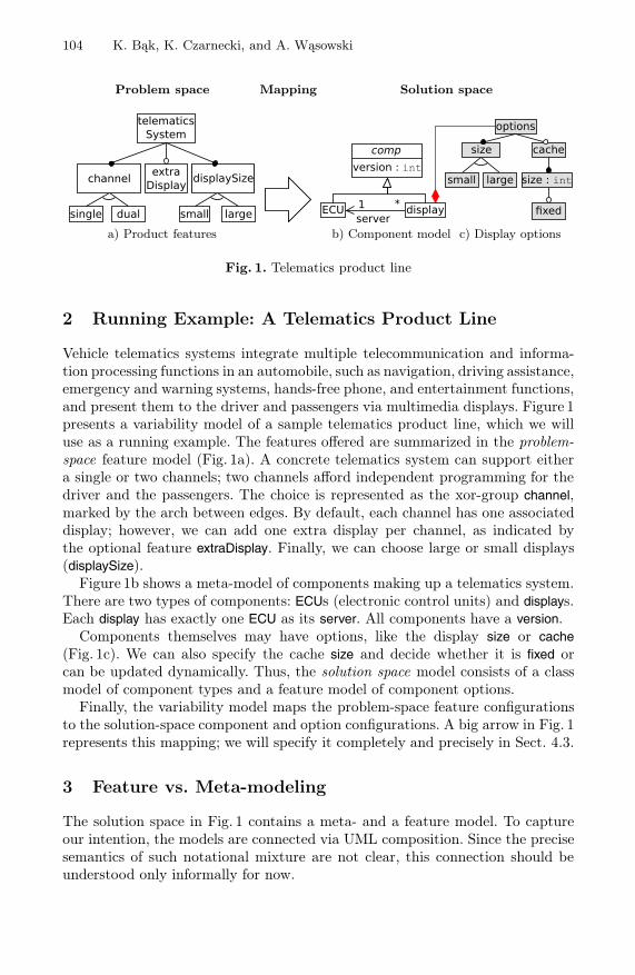
104 K. Bąk, K. Czarnecki, and A. Wąsowski
Problem space Mapping Solution space
telematicsSystem
extraDisplaychannel displaySize
single dual small large server*1
small large
cache
fixed
size : int
options
displayECU
version : intsizecomp
a) Product features b) Component model c) Display options
Fig. 1. Telematics product line
2 Running Example: A Telematics Product Line
Vehicle telematics systems integrate multiple telecommunication and informa-tion processing functions in an automobile, such as navigation, driving assistance,emergency and warning systems, hands-free phone, and entertainment functions,and present them to the driver and passengers via multimedia displays. Figure 1presents a variability model of a sample telematics product line, which we willuse as a running example. The features offered are summarized in the problem-space feature model (Fig. 1a). A concrete telematics system can support eithera single or two channels; two channels afford independent programming for thedriver and the passengers. The choice is represented as the xor-group channel,marked by the arch between edges. By default, each channel has one associateddisplay; however, we can add one extra display per channel, as indicated bythe optional feature extraDisplay. Finally, we can choose large or small displays(displaySize).
Figure 1b shows a meta-model of components making up a telematics system.There are two types of components: ECUs (electronic control units) and displays.Each display has exactly one ECU as its server. All components have a version.
Components themselves may have options, like the display size or cache(Fig. 1c). We can also specify the cache size and decide whether it is fixed orcan be updated dynamically. Thus, the solution space model consists of a classmodel of component types and a feature model of component options.
Finally, the variability model maps the problem-space feature configurationsto the solution-space component and option configurations. A big arrow in Fig. 1represents this mapping; we will specify it completely and precisely in Sect. 4.3.
3 Feature vs. Meta-modeling
The solution space in Fig. 1 contains a meta- and a feature model. To captureour intention, the models are connected via UML composition. Since the precisesemantics of such notational mixture are not clear, this connection should beunderstood only informally for now.

Feature and Meta-Models in Clafer: Mixed, Specialized, and Coupled 105
options
display ECU
root*
server : ECU
*
a) Cardinality-basedfeature model of components
small large
options
cachesize :int
fixed : bool
size1
0..1
b) Meta-model of display options
Fig. 2. Feature model as meta-model and vice versa
We have at least two choices to represent components and options in a singlenotation. The first is to show the entire solution space model using cardinality-based feature modeling [15]. Figure 2a shows the component part of the model(the subfeatures of options are elided). The model introduces a synthetic rootfeature; display and ECU can be multiply instantiated; and display has server sub-feature representing a reference to instances of ECU. Versions could be added toboth display and ECU to match the meta-model in Fig. 1b or we could extend thenotation with inheritance. The latter would bring the cardinality-based featuremodeling notation very close to meta-modeling based on class modeling, posingthe question whether class modeling should not be used for the entire solutionspace model instead.
We explore the class modeling alternative in Fig. 2b. The figure shows onlythe options model, as the component model remains unchanged (as in Fig. 1b).Subfeature relationships are represented as UML composition and feature cardi-nalities correspond to composition cardinalities at the part end. The xor-groupis represented by inheritance and cache size and fixed as attributes of cache.
Representing a feature model as a UML class model worked reasonably wellfor our small example; however, it does have several drawbacks. First, the featuremodel showed fixed as a property of size by nesting; this intention is lost in theclass model. A solution would be to create a separate class size, containing thesize value and a class fixed; thus, adding a subfeature to a feature representedas a class attribute requires refactoring. The name of the new class size wouldclash with the class size representing the display size; thus, we would have torename one of them, or use nested classes, which further complicates the model.Moreover, converting an xor-group to an or-group in feature modeling is simple:the empty arch needs to be replaced by a filled one. For example, displaySize(Fig. 1a) could be converted to an or-group in a future version of the productline to allow systems with both large and small displays simultaneously. Suchchange is tricky in UML class models: we would have to either allow one totwo objects of type displaySize and write an OCL constraint forbidding twoobjects of the same subtype (small or large) or use overlapping inheritance (i.e.,multiple classification). Thus, the representation of feature models in UML incursadditional complexity.

106 K. Bąk, K. Czarnecki, and A. Wąsowski
The examples in Fig. 2 lead us to the following two conclusions:(1) “Cardinality-based feature modeling” is a misnomer. It encompasses multipleinstantiation and references, mechanisms characteristic of class modeling, andcould even be extended further towards class modeling, e.g., with inheritance;however, the result can hardly be called ‘feature modeling’, as it clearly goesbeyond the original scope of feature modeling [22].(2) Existing class modeling notations such as UML and Alloy do not offer first-class support for feature modeling. Feature models can still be represented inthese languages; however, the result carries undesirable notational complexity.The solution to these two issues is to design a (class-based) meta-modeling lan-guage with first-class support for feature modeling. We postulate that such alanguage should satisfy the following design goals:
1. Provide a concise notation for feature modeling2. Provide a concise notation for meta-modeling3. Allow mixing feature models and meta-models4. Use minimal number of concepts and have uniform semantics
The last goal expresses our desire that the new language should unify the con-cepts of feature and class modeling as much as possible, both syntactically andsemantically. In other words, we do not want a hybrid language.
4 Clafer: Meta-modeling with First-Class Support forFeature Modeling
We explain the meaning of Clafer models by relating them to their correspondingUML class models.1 Figure 3 shows the display options feature model in Clafer(a) and the the corresponding UML model (c). Figure 4 shows the componentmeta-model in Clafer; Fig. 1b has the corresponding UML model.
A Clafer model is a set of type definitions, features, and constraints. A type canbe understood as a class or feature type; the distinction is immaterial. Figure 3acontains options as single top-level type definition. The definition contains ahierarchy of features (lines 2-8) and a constraint (lines 10-11); the enclosingtype provides a separate name space for this content. The abstract modifierprohibits creating an instance of the type, unless extended by a concrete type.
A type definition can contain one or more features ; the type options has two(direct) features: size (line 2) and cache (line 6). Features are slots that cancontain one or more instances or references to instances. Mathematically, featuresare binary relations. They correspond to attributes or role names of association orcomposition relationships in UML. For example, in Fig. 4, the feature version (line2) corresponds to the attribute of the class comp in Fig. 1b; and the feature server(line 6) corresponds to the association role name next to the class ECU in Fig. 1b.Features declared using the arrow notation and having no subfeatures, like inserver -> ECU, are reference features, i.e., they hold references to instances. Note1 For more precise documentation including meta-models see gsd.uwaterloo.ca/sle2010

Feature and Meta-Models in Clafer: Mixed, Specialized, and Coupled 107
abstract options1
xor size2
small3
large4
5
cache?6
size -> int7
fixed?8
9
[ small && cache =>10
fixed ]11
abstract <0-*> options {1
<1-1> size 1..1 {2
<0-*> small 0..1 {}3
<0-*> large 0..1 {}4
}5
<0-*> cache 0..1 {6
<0-*> size -> int 1..1 {7
<0-*> fixed 0..1 {}8
}9
}10
[ some this.size.small &&11
some this.cache =>12
some this.cache.size.fixed ]13
}14
small
1 cache 0..1
0..1 0..1 1
0..1
large
xed
cache
options
sizeval :int
size
a) Concise notation b) Full notation c) UML class model
Fig. 3. Feature model in Clafer and corresponding UML class model
that we model integral features, like version (line 2) in Fig. 4, as references. Claferhas only one object representing a given number, which speeds up automatedanalyses.
Features that do not have their type declared using the arrow notation, suchas size (line 2) and cache in Fig. 3a, or have subfeatures, such as size (line 7)in Fig. 3a, are containment features, i.e., features that contain instances. Aninstance can be contained by only one feature, and no cycles in instance con-tainment are allowed. These features correspond to role names at the part endof composition relationships in UML. For example, the feature cache in Fig. 3acorresponds to the role name cache next to the class cache in Fig. 3c. By a UMLconvention, the role name at the association or composition end touching a classis, if not specified, same as the class name.
A containment feature definition creates a feature and, implicitly, a new con-crete type, both located in the same name space. For example, the feature defi-nition cache (line 6) in Fig. 3a defines both the feature cache, corresponding tothe role name in Fig. 3c, and, implicitly, the type cache, corresponding to theclass cache in Fig. 3c. The new type is nested in the type options; in UML thisnesting means that the class cache is an inner class of the class options, i.e., itsfull name is options::cache. Figure 3c shows UML class nesting relations in lightcolor. Class nesting permits two classes named size in a single model, becauseeach enclosing class defines an independent name scope.
abstract comp1
version -> int2
3
abstract ECU extends comp4
abstract display extends comp5
server -> ECU6
‘options7
[ version >= server.version ]8
9
Fig. 4. Class model in Clafer

108 K. Bąk, K. Czarnecki, and A. Wąsowski
The feature size (line 7) in Fig. 3a is a containment feature of general form:the implicitly defined type is a structure containing a reference, here to int, anda subfeature, fixed. This type corresponds to the class cache::size in Fig. 2b.
Features have feature cardinalities, which constrain the number of instances orreferences that a given feature can contain. Cardinality of a feature is specifiedby an interval m..n, where m ∈ N, n ∈ N ∪ {∗}, m ≤ n. Feature cardinalityspecification follows the feature name or its reference type, if any.
Conciseness is an important goal for Clafer; therefore, we provide syntacticsugar for common constructions. Figures 3a and 3b show the same Clafer model;the first one is written in concise notation, while the second one is completelydesugared code with resolved names in constraints.
Clafer provides syntactic sugar similar to syntax of regular expressions: ? orlone (optional) denote 0..1; * or any denote 0..∗; and + or some denote 1..∗. Forexample, cache (line 6) in Fig. 3 is an optional feature. No feature cardinalityspecified denotes 1..1 (mandatory) by default, modulo four exceptions explainedshortly. For example, size (line 7) in Fig. 3a is mandatory.
Features and types have group cardinalities, which constrain the number ofchild instances, i.e., the instances contained by subfeatures. Group cardinalityis specified by an interval 〈m–n〉, with the same restrictions on m and n asfor feature cardinalities, or by a keyword: xor denotes 〈1– 1〉; or denotes 〈1– ∗〉;opt denotes 〈0– ∗〉; and mux denotes 〈0– 1〉; further, each of the three keywordsmakes subfeatures optional by default. If any, a group cardinality specificationprecedes a feature or type name. For example, xor on size (line 2) in Fig. 3a statesthat only one child instance of either small or large is allowed. Because the twosubfeatures small and large have no explicit cardinality attached to them, theyare both optional (cf. Fig. 3b). No explicit group cardinality stands for 〈0– ∗〉,except when it is inherited as illustrated later.
Constraints are a significant aspect of Clafer. They can express dependenciesamong features or restrict string or integer values. Constraints are always sur-rounded by square brackets and are a conjunction of first-order logic expressions.We modeled constraints after Alloy; the Alloy constraint notation is elegant,concise, and expressive enough to restrict both feature and class models. Logicalexpressions are composed of terms and logical operators. Terms either relate val-ues (integers, strings) or are navigational expressions. The value of navigationalexpression is always a relation, therefore each expression must be preceded bya quantifier, such as no, one, lone or some. However, lack of explicit quantifier(Fig. 3a) stands for some (Fig. 3b), signifying that the relation cannot be empty.
Each feature in Clafer introduces a local namespace, which is rather differentfrom namespaces in popular programming languages. Name resolution is impor-tant in two cases: 1) resolving type names used in feature and type definitionsand 2) resolving feature names used in constraints. In both cases, names are pathexpressions, used for navigation like in OCL or Alloy, where the dot operatorjoins two relations. A name is resolved in a context of a feature in up to foursteps. First, it is checked to be a special name like this. Secondly, the name islooked up in subfeatures in breadth-first search manner. If it is still not found,

Feature and Meta-Models in Clafer: Mixed, Specialized, and Coupled 109
the algorithm searches in the top-level definition that contains the feature inits hierarchy. Otherwise, it searches in other top-level definitions. If the namecannot be resolved or is ambiguous within a single step, an error is reported.
Clafer supports single inheritance. In Fig. 4, the type ECU inherits featuresand group cardinality of its supertype. The type display extends comp by addingtwo features and a constraint. The reference feature server points to an existingECU instance. The meaning of ‘options notation is explained in Sect. 4.1.
The constraint defined in the context of display states that display’s versioncannot be lower than server’s version. To dereference the server feature, we usedot, which then returns version.
4.1 Mixing via Quotes and References
Mixing class and feature models in Clafer is achieved via quotation (see line7 in Fig. 4) or references. Syntactically, quotation is just a name of abstracttype preceded by left quote (‘), which in the example is expanded as optionsextends options. The first name indicates a new feature, and the second refersto the abstract type. Semantically, this notation creates a containment featureoptions with a new concrete type display.options, which extends the top-levelabstract type options from Fig. 3a. The concrete type inherits group cardinalityand features of its supertype. By using quotation only the quoted type is shared,but no instances. References, on the other hand, are used for sharing instances.
The following example highlights the difference:
abstract options-- content as in options in Fig. 3a
displayOwningOptions *‘options -- shorthand for options extends options
options
displayOwningOptions
options1
In the above snippet, each instance of displayOwningOptions will have its owninstance of type options, as depicted in the corresponding UML diagram. Othertypes could also quote options to reuse it. Note that Clafer assumes the existenceof an implicit root object ; thus, a feature definition, such as displayOwningOptionsabove, defines both a subfeature of the root object and a new top-level concretetype.
Now consider the following code with corresponding UML diagram:
options *-- content as in options in Fig. 3a
displaySharingOptions *sharedOptions -> options displaySharingOptions
options1*sharedOptions
Each instance of displaySharingOptions has a reference named sharedOptions point-ing to an instance of options. Although there can be many references, they mightall point to the same instance living somewhere outside displaySharingOptions.
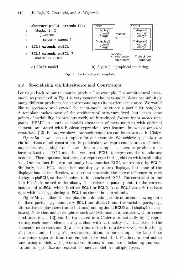
110 K. Bąk, K. Czarnecki, and A. Wąsowski
abstract plaECU extends ECU1
‘display 1..22
[ ~cache3
server = parent ]4
ECU1 extends plaECU5
ECU2 extends plaECU ?6
master -> ECU17
master
ECU2ECU1
display2smalllarge
display1smalllarge
display2smalllarge
display1smalllarge
Legend:radio button(alternative)
check box(optional)
a) Clafer model b) A possible graphical rendering
Fig. 5. Architectural template
4.2 Specializing via Inheritance and Constraints
Let us go back to our telematics product line example. The architectural meta-model as presented in Fig. 4 is very generic: the meta-model describes infinitelymany different products, each corresponding to its particular instance. We wouldlike to specialize and extend the meta-model to create a particular template.A template makes most of the architectural structure fixed, but leaves somepoints of variability. In previous work, we introduced feature-based model tem-plates (FBMT in short) as models (instances of meta-models) with optionalelements annotated with Boolean expressions over features known as presenceconditions [13]. Below, we show how such templates can be expressed in Clafer.
Figure 5a shows such a template for our example. We achieve specializationvia inheritance and constraints. In particular, we represent instances of meta-model classes as singleton classes. In our example, a concrete product musthave at least one ECU and thus we create ECU1 to represent the mandatoryinstance. Then, optional instances are represented using classes with cardinality0..1. Our product line can optionally have another ECU, represented by ECU2.Similarly, each ECU has either one display or two displays, but none of thedisplays has cache. Besides, we need to constrain the server reference in eachdisplay in plaECU, so that it points to its associated ECU. The constraint in line3 in Fig. 5a is nested under display. The reference parent points to the currentinstance of plaECU, which is either ECU1 or ECU2. Also, ECU2 extends the basetype with master, pointing to ECU1 as the main control unit.
Figure 5b visualizes the template in a domain-specific notation, showing boththe fixed parts, e.g., mandatory ECU1 and display1, and the variable parts, e.g.,alternative display sizes (radio buttons) and optional ECU2 and display2 (check-boxes). Note that model templates such as UML models annotated with presenceconditions (e.g., [13]) can be translated into Clafer automatically by 1) repre-senting each model element e by a class with cardinality 0..1 that extends theelement’s meta-class and 2) a constraint of the form p && c <=> e, with p beinge’s parent and c being e’s presence condition. In our example, we keep theseconstraints separate from the template (see Sect. 4.3). Further, in contrast toannotating models with presence conditions, we can use subclassing and con-straints to specialize and extend the meta-model in multiple layers.

Feature and Meta-Models in Clafer: Mixed, Specialized, and Coupled 111
telematicsSystem1
xor channel2
single3
dual4
extraDisplay?5
xor displaySize6
small7
large8
[ dual <=> ECU29
extraDisplay <=> #ECU1.display = 210
extraDisplay <=>11
(ECU2 <=> #ECU2.display = 2)12
small <=> ~plaECU.display.options.size.large13
large <=> ~plaECU.display.options.size.small14
]15
Fig. 6. Feature model with mapping constraints
-- concrete product1
[ dual && extraDisplay && telematicsSystem.size.large && comp.version == 1 ]2
Fig. 7. Constraint specifying a single product
4.3 Coupling via Constraints
Having defined the architectural template, we are ready to expose the remainingvariability points as a product-line feature model. Figure 6 shows this model (cf.Fig. 1a) along with a set of constraints coupling its features to the variabilitypoints of the template. Note that the template allowed the number of displays(ECU1.display and ECU2.display) and the size of every display to vary indepen-dently; however, we further restrict the variability in the feature model, requiringeither all present ECUs to have two displays or all to have no extra display andeither all present displays to be small or all to be large. Also note that we optedto explain the meaning of each feature in terms of the model elements to beselected rather than defining the presence condition of each element in terms ofthe features. Both approaches are available in Clafer, however.
Constraints allow us restricting a model to a single instance. Figure 7 showsa top-level constraint specifying a single product, with two ECUs, two largedisplays per ECU, and all components in version 1. Based on this constraint,we can automatically instantiate the product line using the Alloy analyzer, asdescribed in Sect. 5.2.
5 Evaluation
5.1 Analytical Evaluation
We now discuss to what extent Clafer meets its design goals from Sect. 3.(1) Clafer provides a concise notation for feature modeling. This can be seenby comparing Clafer to TVL, a state-of-the-art textual feature modeling lan-guage [8]. Feature models in Clafer look very similar to feature models in TVL,except that TVL uses explicit keywords (e.g., to declare groups) and braces fornesting. Figure 8a shows the TVL encoding of the feature model from Fig. 3.

112 K. Bąk, K. Czarnecki, and A. Wąsowski
Options group allof {1
Size group oneof { Small, Large },2
opt Cache group allof {3
CacheSize group allof {4
SizeVal { int val; },5
opt Fixed6
}7
},8
Constraint { (Small && Cache) -> Fixed; }9
}10
class Comp {1
reference version : Integer2
}3
4
class ECU extends Comp{ }5
6
class Display extends Comp {7
reference server : ECU8
attribute options : Options9
}10
a) Options feature model in TVL b) Component meta-model in KM3
Fig. 8. Our running example in TVL and KM3
Clafer’s language design reveals four key ingredients allowing a class modelinglanguage to provide a concise notation for feature modeling:
– Containment features: A containment feature definition creates both a fea-ture (a slot) and a type (the type of the slot); for example, all features in Figs.3 and 6 are of this kind. Neither UML nor Alloy provide this mechanism; inthere, a slot and the class used as its type are declared separately.
– Feature nesting: Feature nesting accomplishes instance composition and typenesting in a single construct. UML provides composition, but type nestingis specified separately (cf. Fig. 3c). Alloy has no built-in support for com-position and thus requires explicit parent-child constraints. It also has nosignature nesting, so name clashes need to be avoided using prefixes or alike.
– Group constraints : Clafer’s group constraints are expressed concisely as inter-vals. In UML groups can be specified in OCL, but using a lengthy encoding,explicitly listing features belonging to the group. Same applies to Alloy.
– Constraints with default quantifiers : Default quantifiers on relations, such assome in Fig. 3, allow writing constraints that look like propositional logic,even though their underlying semantics is first-order predicate logic.
(2) Clafer provides a concise notation for meta-modeling. Figure 8b shows themeta-model of Fig. 4 encoded in KM3 [21], a state-of-the-art textual meta-model-ing language. The most visible syntactic difference between KM3 and Clafer isthe use of explicit keywords introducing elements and mandatory braces estab-lishing hierarchy. KM3 cannot express additional constraints in the model. Theyare specified separately, e.g. as OCL invariants.
It is instructive to compare the size of the Clafer and Alloy models of therunning example. With similar code formatting (no comments and blank lines),Clafer representation has 43 LOC and the automatically generated Alloy code isover two times longer. Since the Alloy model contains many long lines, let us alsocompare source file sizes: 1kb for Clafer and over 4kb for Alloy. The code gener-ator favors conciseness of the translation over uniformity of the generated code.Still, in the worst case, the lack of the previously listed constructs makes Alloy

Feature and Meta-Models in Clafer: Mixed, Specialized, and Coupled 113
models necessarily larger. Other language differences tip the balance further infavor of Clafer. For example, an abstract type definition in Clafer guaranteesthat the type will not be automatically instantiated; however, unextended ab-stract sets can be still instantiated by Alloy Analyzer. Therefore, each abstractsignature in Alloy needs to be extended by an additional signature.(3) Clafer allows mixing feature and meta-models. Quotations allow reusing fea-ture or class types in multiple locations; references allow reusing both types andinstances. Feature and class models can be related via constraints (Fig. 6).(4) Clafer tries to use a minimal number of concepts and has uniform seman-tics. While integrating feature modeling into meta-modeling, our goal was toavoid creating a hybrid language with duplicate concepts. In Clafer, there is nodistinction between class and feature types. Features are relations and, besidestheir obvious role in feature modeling, they also play the role of attributes inmeta-modeling. We also contribute a simplification to feature modeling: Claferhas no explicit feature group construct; instead, every feature can use a groupcardinality to constrain the number of children. This is a significant simplifica-tion, as we no longer need to distinguish between “grouping features” (featuresused purely for grouping, such as menus) and feature groups. The grouping in-tention and grouping cardinalities are orthogonal: any feature can be annotatedas a grouping feature and any feature may chose to impose grouping constraintson children. Finally, both feature and class modeling have a uniform semantics:a Clafer model instance, just like Alloy’s, is a set of relations.
5.2 Experimental Evaluation
Our experiment aims to show that Clafer can express a variety of realistic featuremodels, meta-models and model templates and that useful analyses can be per-formed on these encodings in reasonable time. Then it follows that the richnessof Clafer’s applications, does not come at a cost of lost analysis potential withrespect to models in more specialized languages.
The experiment methodology is summarized in the following steps:
1. Identify a set of models representative for the three main use cases of Clafer:feature modeling, meta-modeling, and mixed feature and meta-modeling.
2. Select representative analyses. We studied the analyses in published litera-ture and decided to focus on a popular class of analyses, which reduce tomodel instance finding. These include inconsistency detection, element live-ness analysis, offline and interactive configuration, guided editing, etc. Sinceall these have similar performance characteristics, we decided to use modelinstance finding, consistency and element liveness analysis as representative.
3. Translate models into Clafer and record observations. We created automatictranslators for converting models to Clafer if it was enough to apply simplerewriting rules. In other cases, translation was done manually.
4. Run the analyses and reporting performance results. The analyses are imple-mented by using our Clafer-to-Alloy translator, and then employing AlloyAnalyzer (which is an instance finder) to perform the analysis.

114 K. Bąk, K. Czarnecki, and A. Wąsowski
The Clafer-to-Alloy translator is written in Haskell and comprises several chainedmodules: lexer, layout resolver, parser, desugarer, semantic analyzer, and codegenerator. Layout resolver makes braces grouping subfeatures optional. Clafer iscomposed of two languages: the core and the full language. The first one is a min-imal language with well-defined semantics. The latter is built on top of the corelanguage and provides large amount of syntactic sugar (cf. Fig. 3). Semantic an-alyzer resolves names and deals with inheritance. The code generator translatesthe core language into Alloy. The generator has benefited from the knowledgeabout the class of models it is working with to optimize the translation, in thesame way as analyzers for specialized languages have this knowledge.
The experiment was executed on a laptop with a Core Duo 2 @2.4GHz pro-cessor and 2.5GB of RAM, running Linux. Alloy Analyzer was configured touse Minisat as a solver. All Clafer and generated Alloy models are available atgsd.uwaterloo.ca/sle2010. In the subsequent paragraphs we present and discussthe results for the three subclasses of models.
Feature Models. In order to find representative models we have consulted SPLOT[27] — a popular repository of feature models. We have succeeded in automat-ically translating all 58 models from SPLOT to Clafer (non-generated, human-made models; available as of July 4th, 2010). These include models with andwithout cross-tree constraints, ranging from a dozen to hundreds of features.
Results for all models are available online at the above link. Here, we reportthe most interesting cases together with further four, which have been randomlygenerated; all listed in Table 1. Digital Video Systems is a small example with fewcross-tree constraints. Dell Laptops models a set of laptops offered by Dell in 2009.This is one of few models that contains more constraints than features. ArcadeGame describes a product line of computer games; it contains tens of featuresand constraints. EShop [25] is the largest realistic model that we have foundon SPLOT. It is a domain model of online stores. The remaining models arerandomly generated using SPLOT, with a fixed 10% constraint/variable ratio.
We checked consistency of each model by instance finding. Table 1 presentssummary of results. The analysis time was less then a second for up to severalhundred features and less than a minute for up to several thousand features. In-terestingly, the biggest bottleneck was the Alloy Analyzer itself (which translatesAlloy into a CNF formula)—reasoning about the CNF formula in a SAT-solvertakes no more than hundreds of milliseconds.
Meta-Models. In order to identify representative meta-models, we have turnedto the Ecore Meta-model Zoo (www.emn.fr/z-info/atlanmod/index.php/Ecore), fromwhere we have selected the following meta-models: AWK Programs, ATL, ANT, Bib-Tex, UML2, ranging from tens to hundreds of elements. We translated all theseinto Clafer automatically. One interesting mapping is the translation of ERef-erence elements with eOpposite attribute (symmetric reference), as there is nofirst-class support for symmetric references in Clafer. We modeled them as con-straints relating references with their symmetric counterparts. Moreover we havenot handled multiple inheritance in our translation.

Feature and Meta-Models in Clafer: Mixed, Specialized, and Coupled 115
Since none of these meta-models contained OCL constraints, we extractedOCL constraints from the UML specification [29] and manually added themto the Clafer encoding of UML2. We did observe certain patterns during thattranslation and believe that this task can be automated for a large class ofconstraints. Table 2 presents sample OCL constraints translated into Clafer.Each constraint, but last, is written in a context of some class. Their intuitivemeanings are as follows: 1) ownedReception is empty if there is no isActive; 2)endType aggregates all types of memberEnds; 3) if memberEnd’s aggregation isdifferent from none then there are two instances of memberEnd; 4) there areno two types of the same names. All Clafer encodings of the meta-models areavailable at the above link.
There are several reasons why Clafer constraints are more concise and uni-form compared with OCL invariants. Similarly to Alloy, every Clafer definitionis a relation. This approach, eliminates extra constructions such as OCL’s collect,allInstances. Finally, assuming the default some quantifier before relational op-erations (e.g. memberEnd.aggregation - none), we can treat result of an operationas if it was a propositional formula, thus eliminating extra exists quantifiers.
We applied automated analyses to slices of the UML2 meta-model: Class Di-agram from [10], State Machines, and Behaviors (Table 3). Each slice has tensof classes and our goal was to include a wide range of OCL constraints. We
Table 1. Results of consistency analysis for feature models expressed in Clafer
model name nature size [# features] [# constraints] running time [s]
Digital Video System Realistic 26 3 0.012Dell Laptops Realistic 46 110 0.025Arcade Game Realistic 61 34 0.040eShop Realistic 287 21 0.15FM-500-50-1 Generated 500 50 0.45FM-1000-100-2 Generated 1000 100 1.5FM-2000-200-3 Generated 2000 200 4.5FM-5000-500-4 Generated 5000 500 28.0
Table 2. Constraints in OCL and Clafer
Context OCL Clafer
Class (not self.isActive) implies ∼isActive => no ownedReceptionself.ownedReception->isEmpty()
Association self.endType = self.memberEnd-> endType = memberEnd.typecollect(e | e.type)
Association self.memberEnd->exists(aggregation memberEnd.aggregation - none =><> Aggregation::none) implies #memberEnd = 2self.memberEnd->size() = 2
– Type.allInstances() -> forAll (t1, t2 | all disj t1, t2 : Type | t1.name != t2.namet1 <> t2 implies t1.name <> t2.name)
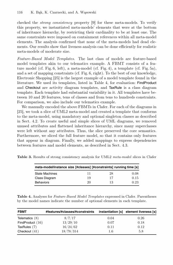
116 K. Bąk, K. Czarnecki, and A. Wąsowski
checked the strong consistency property [9] for these meta-models. To verifythis property, we instantiated meta-models’ elements that were at the bottomof inheritance hierarchy, by restricting their cardinality to be at least one. Thesame constraints were imposed on containment references within all meta-modelelements. The analysis confirmed that none of the meta-models had dead ele-ments. Our results show that liveness analysis can be done efficiently for realisticmeta-models of moderate size.
Feature-Based Model Templates. The last class of models are feature-basedmodel templates akin to our telematics example. A FBMT consists of a fea-ture model (cf. Fig. 6, left), a meta-model (cf. Fig. 4), a template (cf. Fig. 5a),and a set of mapping constraints (cf. Fig. 6, right). To the best of our knowledge,Electronic Shopping [25] is the largest example of a model template found in theliterature. We used its templates, listed in Table 4, for evaluation: FindProductand Checkout are activity diagram templates, and TaxRule is a class diagramtemplate. Each template had substantial variability in it. All templates have be-tween 10 and 20 features, tens of classes and from tens to hundreds constraints.For comparison, we also include our telematics example.
We manually encoded the above FBMTs in Clafer. For each of the diagrams in[25], we took a slice of UML2 meta-model and created a template that conformsto the meta-model, using mandatory and optional singleton classes as describedin Sect. 4.2. To create useful and simple slices of UML diagrams, we removedunused attributes and flattened inheritance hierarchy, since many superclasseswere left without any attributes. Thus, the slice preserved the core semantics.Furthermore, we sliced the full feature model, so that it contains only featuresthat appear in diagram. Finally, we added mappings to express dependenciesbetween features and model elements, as described in Sect. 4.3.
Table 3. Results of strong consistency analysis for UML2 meta-model slices in Clafer
meta-model/instance size [#classes] [#constraints] running time [s]
State Machines 11 28 0.08Class Diagram 19 17 0.15Behaviors 20 13 0.23
Table 4. Analyses for Feature-Based Model Templates expressed in Clafer. Parenthesesby the model names indicate the number of optional elements in each template.
FBMT #features/#classes/#constraints instantiation [s] element liveness [s]
Telematics (8) 8/7/17 0.04 0.26FindProduct (16) 13/29/10 0.07 0.18TaxRules (7) 16/24/62 0.11 0.12Checkout (41) 18/78/314 1.6 5.8

Feature and Meta-Models in Clafer: Mixed, Specialized, and Coupled 117
We performed two types of analyses on FBMTs. First, we created samplefeature configurations (like in Fig. 7) and instantiated templates in the AlloyAnalyzer. We inspected each instance and verified that it was the expected one.
Second, we performed element liveness analysis for the templates. The analy-sis is similar to element liveness for meta-models [9], but now applied to templateelements. We performed the analysis by repeated instance finding; in each iter-ation we required the presence of groups of non-exclusive model elements.
Table 4 presents summary of inspected models and times of analyses. Oftenthe time of liveness analysis is very close to the time of instantiation multipliedby the number of element groups. For instance, for FindProduct, liveness analysiswas three times longer than time of instantiation, because elements were ar-ranged into 3 groups of non-conflicting elements. This rule holds when the AlloyAnalyzer uses the same scope for element instances.
We consider our results promising, since we obtained acceptable timings forslices of realistic models, without fully exploiting the potential of Alloy. Theresults can clearly be further improved by better encoding of slices (for example,representing activity diagram edges as relations instead of sets in Alloy) andusing more intelligent slicing methods; e.g. some constraints are redundant, suchas setting source and target edges in ActivityNodes, so removing these constraintswould speed up reasoning process. However already now we can see that Claferis a suitable vehicle for specifying FBMTs and analyzing them automatically.
Threats to Validity
External Validity. Our evaluation is based on the assumption that we choserepresentative models and useful and representative analyses.
All models, except the four randomly generated feature models, were cre-ated by humans to model real-word artifacts. As all, except UML2, come fromacademia, there is no guarantee that they share characteristics with industrialmodels. Majority of practical models have less than a thousand features [24], soreasoning about corresponding Clafer models is feasible and efficient. Perhapsthe biggest real-world feature model up to date is the Linux Kernel model (al-most 5500 features and thousands of constraints) [31]. It would presently pose achallenge for our tools. Working with models of this size requires proper engi-neering of analyses. Our objective here was to demonstrate feasibility of analyses.We will continue to work on robust tools for Clafer in future.
We believe that the slices of UML2 selected for the experiment are represen-tative of the entire meta-model because we picked the parts with more complexconstraints. While there are not many existing FBMTs to choose from, the e-commerce example [25] was reversed engineered from the documentation of anIBM e-commerce platform, which makes the model quite realistic.
Not all model analyses can be reduced to instance finding performed usingcombinatorial solvers (relational model finder in case of Alloy [34]). Howevercombinatorial analyses belong to most widely recognized and effective [7].

118 K. Bąk, K. Czarnecki, and A. Wąsowski
Instance finding for models has similar uses to testing and debugging forprograms [19]—it helps to uncover flaws in models, assists in evolution andconfiguration. For example it helped us discover that our original Clafer codewas missing constraints (lines 9–10 and 14–15 in Fig. 5a and line 14 in Fig. 6).Some software platforms already provide configuration tools using reasoners; forexample, Eclipse uses a SAT solver to help users select valid sets of plug-ins [26].
Liveness analysis for model elements has been previously exploited, for in-stance in [33, 9]. Tartler et al. [33] analyze liveness of features in the Linux kernelcode, reporting about 60 previously unreported dead features in the released ker-nel versions. Linux is not strictly a feature-based model template, but its buildarchitecture, which relies on (a form of) feature models and presence conditionson code (conditional compilation) highly resembles our model templates.
Analyzers based on instance finding solve an NP-hard problem. Thus no hardguarantees can be given for their running times. Although progress in solvertechnologies has placed these problems in the range of practically tractable,there do exist instances of models and meta-models, which will effectively breakthe performance of our tools. Our experiments aim at showing that this doesnot happen for realistic models.
There exist more sophisticated analyzes (and classes of models) that cannot beaddressed with Clafer infrastructure, and are not reflected in our experiment. Forexample instance finding is limited to instances of bounded size. It is possibleto build sophisticated meta-models that only have very large instances. Thisproblem is irrelevant for feature models and model templates as they allow nono classes that can be instantiated without bounds.
Moreover special purpose languages may require more sophisticated analy-ses techniques such as behavioral refinement checking, model checking, modelequivalence checking, etc. These properties typically go beyond static semanticsexpressed in meta-models and thus are out of scope for generic Clafer tools.
Internal Validity. Translating models from one language to another can intro-duce errors and change semantics of the resulting model.
We used our own tools to convert SPLOT and Ecore models to Clafer andthen to translate Clafer to Alloy. We translated FBMTs and OCL constraintsmanually. The former is rather straightforward; the latter is more involved. Wepublish all the models so that their correctness can be reviewed independently.
Another threat to correctness is the slice extraction for UML2 and e-commercemodels. Meta-model slicing is a common technique used to speed-up model anal-yses, where reasoner processes only relevant parts of the meta-model. We per-formed it manually, while making sure that all parts relevant to the selectedconstraints were included; however, the technique can be automated [30].
The correctness of the analyses relies on the correctness of the Clafer-to-Alloy translator and the Alloy analyzer. The Alloy analyzer is a mature piece ofsoftware. We tested Clafer-to-Alloy translator by translating sample models toAlloy and inspecting the results.

Feature and Meta-Models in Clafer: Mixed, Specialized, and Coupled 119
6 Related Work
We have already mentioned related work on model analysis; here we focus onwork related to our main contribution, Clafer’s novel language design.
Asikainen and Männistö present Forfamel, a unified conceptual foundation forfeature modeling [4]. The basic concepts of Forfamel and Clafer are similar; bothinclude subfeature, attribute, and subtype relations. The main difference is thatClafer’s focus is to provide concise concrete syntax, such as being able to definefeature, feature type, and nesting by stating an indented feature name. Also, theconceptual foundations of Forfamel and Clafer differ; e.g., features in Forfamelcorrespond to Clafer’s instances, but features in Clafer are relations. Also, afeature instance in Forfamel can have several parents; in Clafer, an instancehas at most one parent. These differences likely stem from the difference inperspective: Forfamel takes a feature modeling perspective and aims at providinga foundation unifying the many existing extensions to feature modeling; Claferlimits feature modeling to its original FODA scope [22], but integrates it intoclass modeling. Finally, Forfamel considers a constraint language as out of scope,hinting at OCL. Clafer comes with a concise constraint notation.
TVL is a textual feature modeling language [8]. It favors the use of explicit key-words, which some software developers may prefer. The language covers Booleanfeatures and features of other primitive types such as integer. The key differenceis that Clafer is also a class modeling language with multiple instantiation, ref-erences, and inheritance. It would be interesting to provide a translation fromTVL to Clafer. The opposite translation is only partially possible.
As mentioned earlier, class-based meta-modeling languages, such as KM3 [21]and MOF [28] cannot express feature models as concisely as Clafer.
Nivel is a meta-modeling language, which was applied to define feature andclass modeling languages [3]. It supports deep instantiation, enabling concisedefinitions of languages with class-like instantiation semantics. Clafer’s purposeis different: to provide a concise notation for combining feature and class modelswithin a single model. Nivel could be used to define the abstract syntax of Clafer,but it would not be able to naturally support our concise concrete syntax.
Clafer builds on our several previous works, including encoding feature mod-els as UML class models with OCL [16]; a Clafer-like graphical profile for Ecore,having a bidirectional translation between an annotated Ecore model and itsrendering in the graphical syntax [32]; and the Clafer-like notation used to spec-ify framework-specific modeling languages [2]. None of these works provideda proper language definition and implementation like Clafer; also, they lackedClafer’s concise constraint notation.
Gheyi et al. [17] pioneered translating Boolean feature models into Alloy.Anastasakis et al. [1] automatically translated UML class diagrams with OCLconstraints to Alloy. Clafer covers both types of models.
Relating problem-space feature models and solution-space models has a longtradition. For example, feature models have been used to configure model tem-plates before [13, 18]. That work considered model templates as superimposed in-stances of a metamodel and presence conditions attached to individual elements

120 K. Bąk, K. Czarnecki, and A. Wąsowski
of the instances; however, the solution in Sect. 4.2 implements model templatesas specializations of a metamodel. Such a solution allows us treating the fea-ture model, the metamodel, and the template at the same metalevel, simply asparts of a single Clafer model. This design allows us to elegantly reuse a singleconstraint language at all these levels. As another example, Janota and Botter-weck show how to relate feature and architectural models using constraints [20].Again, our work differs from this work in that our goal is to provide such integra-tion within a single language. Such integration is given in Kumbang [5], which isa language that supports both feature and architectural models, related via con-straints. Kumbang models are translated to Weight Constraint Rule Language(WCRL), which has a reasoner supporting model analysis and instantiation.Kumbang provides a rich domain-specific vocabulary, including features, com-ponents, interfaces, and ports; however, Clafer’s goal is a minimal clean languagecovering both feature and class modeling, and serving as a platform to derivesuch domain specific languages, as needed.
7 Conclusion
The premise for our work are usage scenarios mixing feature and class modelstogether, such as representing components as classes and their configurationoptions as feature hierarchies and relating feature models and component modelsusing constraints. Representing both types of models in single languages allowsus to use a common infrastructure for model analysis and instantiation.
We set off to integrate feature modeling into class modeling, rather than try-ing to extend feature modeling as previously done [15]. We propose the conceptof a class modeling language with first-class support for feature modeling anddefine a set of design goals for such languages. Clafer is an example of such alanguage, and we demonstrate that it satisfies these goals. The design of Claferrevealed that a class modeling language can provide a concise notation for featuremodeling if it supports containment feature definitions, feature nesting, groupcardinalities, and constraints with default quantifiers. Our design contributes aprecise characterization of the relationship between feature and class modelingand a uniform framework to reason about both feature and class models.
References
1. Anastasakis, K., Bordbar, B., Georg, G., Ray, I.: On challenges of model transfor-mation from UML to Alloy. Software and Systems Modeling 9(1) (2008)
2. Antkiewicz, M., Czarnecki, K., Stephan, M.: Engineering of framework-specificmodeling languages. IEEE TSE 35(6) (2009)
3. Asikainen, T., Männistö, T.: Nivel: a metamodelling language with a formal se-mantics. Software and Systems Modeling 8(4) (2009)
4. Asikainen, T., Männistö, T., Soininen, T.: A unified conceptual foundation forfeature modelling. In: SPLC 2006 (2006)
5. Asikainen, T., Männistö, T., Soininen, T.: Kumbang: A domain ontology for mod-elling variability in software product families. Adv. Eng. Inform. 21(1) (2007)

Feature and Meta-Models in Clafer: Mixed, Specialized, and Coupled 121
6. Bart Veer, J.D.: The eCos Component Writer’s Guide (2000)7. Benavides, D., Segura, S., Ruiz-Cortés, A.: Automated analysis of feature models
20 years later: a literature review. Information Systems 35(6) (2010)8. Boucher, Q., Classen, A., Faber, P., Heymans, P.: Introducing TVL, a text-based
feature modelling language. In: VaMoS 2010 (2010)9. Cabot, J., Clarisó, R., Riera, D.: Verification of UML/OCL Class Diagrams Using
Constraint Programming. In: MoDeVVA 2008 (2008)10. Cariou, E., Belloir, N., Barbier, F., Djemam, N.: Ocl contracts for the verification
of model transformations. In: Schürr, A., Selic, B. (eds.) MODELS 2009. LNCS,vol. 5795. Springer, Heidelberg (2009)
11. Clauß, M., Jena, I.: Modeling variability with UML. In: Dannenberg, R.B. (ed.)GCSE 2001. LNCS, vol. 2186. Springer, Heidelberg (2001)
12. Czarnecki, K., Pietroszek, K.: Verifying feature-based model templates againstwell-formedness ocl constraints. In: GPCE 2006 (2006)
13. Czarnecki, K., Antkiewicz, M.: Mapping features to models: A template approachbased on superimposed variants. In: Glück, R., Lowry, M. (eds.) GPCE 2005.LNCS, vol. 3676, pp. 422–437. Springer, Heidelberg (2005)
14. Czarnecki, K., Bednasch, T., Unger, P., Eisenecker, U.: Generative programmingfor embedded software: An industrial experience report. In: Batory, D., Blum, A.,Taha, W. (eds.) GPCE 2002. LNCS, vol. 2487. Springer, Heidelberg (2002)
15. Czarnecki, K., Helsen, S., Eisenecker, U.: Formalizing cardinality-based featuremodels and their specialization. SPIP 10(1) (2005)
16. Czarnecki, K., Kim, C.H.: Cardinality-based feature modeling and constraints: Aprogress report. In: OOPSLA 2005 Workshop on Software Factories (2005)
17. Gheyi, R., Massoni, T., Borba, P.: A theory for feature models in Alloy. In: FirstAlloy Workshop (2006)
18. Heidenreich, F., Kopcsek, J., Wende, C.: FeatureMapper: Mapping Features toModels. In: ICSE 2008 (2008)
19. Jackson, D.: Software Abstractions: Logic, Language, and Analysis. The MIT Press,Cambridge (2006)
20. Janota, M., Botterweck, G.: Formal approach to integrating feature and architec-ture models. In: Fiadeiro, J.L., Inverardi, P. (eds.) FASE 2008. LNCS, vol. 4961,pp. 31–45. Springer, Heidelberg (2008)
21. Jouault, F., Bézivin, J.: KM3: a DSL for Metamodel Specification. In: IFIP 2006(2006)
22. Kang, K., Cohen, S., Hess, J., Nowak, W., Peterson, S.: Feature-oriented domainanalysis (FODA) feasibility study. Tech. Rep. CMU/SEI-90-TR-21, CMU (1990)
23. Kang, K.C.: FODA: Twenty years of perspective on feature modeling. In: VaMoS2010 (2010)
24. Kästner, C.: Virtual Separation of Concerns: Toward Preprocessors 2.0. Ph.D. the-sis, University of Magdeburg (2010)
25. Lau, S.Q.: Domain Analysis of E-Commerce Systems Using Feature-Based ModelTemplates. Master’s thesis, University of Waterloo (2006)
26. Le Berre, D., Rapicault, P.: Dependency management for the Eclipse ecosystem:Eclipse p2, metadata and resolution. In: IWOCE 2009 (2009)
27. Mendonça, M., Branco, M., Cowan, D.: S.P.L.O.T. - Software Product Lines OnlineTools. In: OOPSLA 2009 (2009)
28. OMG: Meta Object Facility (MOF) Core Specification (2006)29. OMG: OMG Unified Modeling Language (2009)30. Shaikh, A., Clarisó, R., Wiil, U.K., Memon, N.: Verification-Driven Slicing of
UML/OCL Models. In: ASE 2010 (2010)

122 K. Bąk, K. Czarnecki, and A. Wąsowski
31. She, S., Lotufo, R., Berger, T., Wasowski, A., Czarnecki, K.: Variability model ofthe linux kernel. In: VaMoS 2010 (2010)
32. Stephan, M., Antkiewicz, M.: Ecore.fmp: A tool for editing and instantiating classmodels as feature models. Tech. Rep. 2008-08, Univeristy of Waterloo (2008)
33. Tartler, R., Sincero, J., Lohmann, D.: Dead or Alive: Finding Zombie Features inthe Linux Kernel. In: FOSD 2009 (2009)
34. Torlak, E., Jackson, D.: Kodkod: A relational model finder. In: Grumberg, O.,Huth, M. (eds.) TACAS 2007. LNCS, vol. 4424, pp. 632–647. Springer, Heidelberg(2007)

Support for the
Evolution of C++ Generic Functions
Peter Pirkelbauer1, Damian Dechev2, and Bjarne Stroustrup3
1 Lawrence Livermore National LaboratoryCenter for Applied Scientific Computing
Livermore, CA [email protected] University of Central Florida
Department of Electrical Engineering and Computer ScienceOrlando, FL [email protected]
3 Texas A&M UniversityDepartment of Computer Science and Engineering
College Station, TX [email protected]
Abstract. The choice of requirements for an argument of a generic typeor algorithm is a central design issue in generic programming. In thecontext of C++, a specification of requirements for a template argumentor a set of template arguments is called a concept.
In this paper, we present a novel tool, TACE (template analysisand concept extraction), designed to help programmers understand therequirements that their code de facto imposes on arguments and helpsimplify and generalize those through comparisons with libraries of well-defined and precisely-specified concepts. TACE automatically extractsrequirements from the body of function templates. These requirementsare expressed using the notation and semantics developed by the ISOC++ standards committee. TACE converts implied requirements intoconcept definitions and compares them against concepts from a repos-itory. Components of a well-defined library exhibit commonalities thatallow us to detect problems by comparing requirements from many com-ponents: Design and implementation problems manifest themselves asminor variations in requirements. TACE points to source code that can-not be constrained by concepts and to code where small modificationswould allow the use of less constraining concepts. For people who use aversion of C++ with concept support, TACE can serve as a core enginefor automated source code rejuvenation.
1 Introduction
A fundamental idea of generic programming is the application of mathematicalprinciples to the specification of software abstractions [22]. ISO C++ [15][24]supports generic programming through the use of templates. Unfortunately, itdoes not directly support the specification of requirements for arguments to
B. Malloy, S. Staab, and M. van den Brand (Eds.): SLE 2010, LNCS 6563, pp. 123–142, 2011.c© Springer-Verlag Berlin Heidelberg 2011

124 P. Pirkelbauer, D. Dechev, and B. Stroustrup
generic types and functions [23]. However, research into language-level supportfor specifying such requirements, known as concepts, for C++ has progressed tothe point where their impact on software can be examined [13][7][14]. Our workis aimed at helping programmers cope with the current lack of direct supportfor concepts and ease the future transition to language-supported concepts.
Templates are a compile-time mechanism to parameterize functions andclasses over types and values. When the concrete template argument type be-comes known to the compiler, it replaces the corresponding type parameter(template instantiation), and type checks the instantiated template body. Thiscompilation model is flexible, type safe, and can lead to high performance code[10]. For over a decade, C++ templates have helped deliver programs that areexpressive, maintainable, efficient, and organized into highly reusable compo-nents [25]. Many libraries, such as the C++ Standard Template Library (STL) [5],the BOOST graph library [21], and the parallel computation system, STAPL [4],for which adaptability and performance are paramount, rest on the templatemechanism.
C++ currently does not allow the requirements for the successful instantia-tion of a template to be explicitly stated. These requirements must be foundin documentation or inferred from the template body. For attempts to instan-tiate a template with types that do not meet its requirements, current compil-ers often fail with hard to understand error messages [13]. Also, C++ providesonly weak support for overloaded templates. While numerous programming tech-niques [1][3][18][20] offer partial solutions, they tend to raise the complexity.
Concepts [13][7][14] were developed to provide systematic remedies and deliverbetter support for the design and development of generic programs. As definedfor C++0x, concepts improve expressiveness, make error messages more precise,and provide better control of the compile-time resolution of templates. Impor-tantly, the use of concepts does not incur runtime overhead when compared totemplates not using concepts. Despite many years design efforts, implementa-tion work, and experimental use, concerns about usability, scalability, and thetime needed to stabilize a design prevented concepts from being included as alanguage mechanism in the next revision of C++ [27][26]. However, we are leftwith a notation and a set of concepts developed for the STL and other librariesthat can be used to describe and benchmark our use of design-level concepts.
In this paper, we present a novel tool for template analysis and concept ex-traction, TACE, that addresses some of these concerns. TACE extracts conceptrequirements from industrial-strength C++ code and helps apply concepts tounconstrained templated code. The paper offers the following contributions:
– A strategy for evolving generic code towards greater generality, greater uni-formity, and more precise specification.
– Type level evaluation of uninstantiated function templates and automaticextraction of sets of requirements on template arguments.
– Concept analysis that takes called functions into account.
Experience with large amounts of generic C++ code and the development ofC++ generic libraries, such as the generic components of the C++0x standard

Evolution of C++ Generic Functions 125
library [6], shows that the source code a template is not an adequate specificationof its requirements. Such a definition is sufficient for type safe code generation,but even expert programmers find it hard to provide implementations that donot accidentally limit the applicability of a template (compared to its informaldocumentation). It is also hard to precisely specify template argument require-ments and to reason about those.
Consequently, there is wide agreement in the C++ community that a formalstatement of template argument requirements in addition to the template bodyis required. Using traditional type deduction techniques [8] modified to copewith C++, TACE generates such requirements directly from code. This helpsprogrammers see the implications of implementation choices. Furthermore, theset of concepts generated from an implementation is rarely the most reusableor the simplest. To help validate a library implementation TACE compares thegenerated (implied) concepts to pre-defined library concepts.
Fig. 1. The TACE tool chain
Fig. 1 shows TACE’s tool chain. TACE utilizes the Pivot source-to-sourcetransformation infrastructure [11] to collect and analyze information about C++function templates. The Pivot’s internal program representation (IPR) preserveshigh-level information present in the source code - it represents uninstantiatedtemplates and is ready for concepts. TACE analyzes expressions, statements, anddeclarations in the body of function templates and extracts the requirements ontemplate arguments. It merges the requirements with requirements extractedfrom functions that the template body potentially invokes. The resulting sets ofrequirements can be written out as concept definitions.
However, our goal is to find higher-level concepts that prove useful at thelevel of the design of software libraries. In particular, we do not just want to findthe requirements of a particular implementation of an algorithm or the absoluteminimal set of requirements. We want to discover candidates for concepts thatare widely usable in interface specifications for algorithms. To recognize suchconcepts we need the “advice” of an experienced human. TACE achieves this bymatching the extracted sets of requirements against concepts stored in a concept

126 P. Pirkelbauer, D. Dechev, and B. Stroustrup
repository (e.g., containing standard concepts). In addition to reporting matches,the tool also reports close misses. In some cases, this allows programmers to re-formulate their code to facilitate types that model a weaker concept. TACE doesnot try to discover semantic properties of a concept (“axioms” [12]). In general,doing so is beyond the scope of static analysis. Test results for STL indicatethat our tool is effective when used in conjunction with a concept repositorythat contains predefined concepts.
The rest of the paper is organized as follows: §2 provides an overview of C++with concepts, §3 presents the extraction of requirements from bodies of tem-plate functions, §4 describes requirement integration and reduction; §5 discussesmatching the extracted requirements against predefined concepts from a repos-itory, §7 discusses related work, and §8 presents a conclusion and an outlook onsubsequent work.
2 Concepts for C++
Concepts as designed for C++0x [13][7][14] provide a mechanism to express con-straints on template arguments as sets of syntactic and semantic requirements.
Syntactic requirements describe requirements such as associated functions,types, and templates that allow the template instantiation to succeed. Considerthe following template, which determines the distance between two iterators:template<typename Iterator>size t distance(Iterator first, Iterator last) {
size t n = 0;while (first != last) { ++first; ++n; }return n;
}
The function distance requires types that substitute for the type parameterIterator have a copy constructor (to copy the arguments), a destructor (todestruct the argument at the end of the scope), an inequality (!=) operator, andan increment (++) operator. A requirement’s argument type can be derived fromthe source code. Requirements can be stated using a C++ signature like notation.concept DistanceRequirements<typename T> {
T::T(const T&); // copy constructorT::˜T(); // destructorbool operator!=(T, T);void operator++(T);
}
In order not to over-constrain templates, function signatures of types that modelthe concept need not match the concept signature exactly. Signatures in conceptsallow automatic conversions of argument types. This means that an implemen-tation of operator!= can accept types that are constructable from T.
The return type of a functional requirement has to be named but can remainunbound. The following example shows a function with two parameters of typeT, where T is a template argument constrained by the concept TrivialIterator.The function tests whether the return values of the operator* are equal. The typeof the return values is irrelevant as long as there exists an operator== that can

Evolution of C++ Generic Functions 127
compare the two. The result type of the equality comparison must be convertibleto bool.template <TrivialIterator T>bool same elements(T lhs, T rhs) {
return (∗lhs == ∗rhs);}
Concepts introduce associated types to model such types. The following conceptdefinition of TrvialIterator introduces such an associated type ValueType tospecify the return type of operator*. Associated types can be constrained bynested requirements (e.g., the requires clause).concept TrivialIterator<typename T> {
typename ValueType;// nested requirementsrequires EqualityComparable<ValueType>; // operator== of ValueTypeValueType operator∗(T); // deref operator∗. . .
}
The compiler will use the concept definitions to type check expressions, declara-tions, and statements of the template body without instantiating it. Any type(or combination of types) that defines the required operations and types is amodel of the concept. These types can be used for template instantiation.
Semantic requirements describe behavioral properties, such as the equivalenceof operations or runtime complexity. Types that satisfy the semantic require-ments are guaranteed to work properly with a generic algorithm. Axioms modelsome behavioral properties. Axioms can specify the equivalence of operations.The two operations are separated by an operator <=>. In the following example,the axiom indirect deref specifies that the operations of the left and right sideof <=> produce the same result. This is the case for pointers or random accessiterators. Compilers are free to use axioms for code optimizations.concept Pointer<typename T> {
typename data;data operator∗(T);T operator+(T, size t);data operator[](T, size t);
axiom indirect deref(T t, size t n) {t[n] <=> ∗(t+n);
}}
Concepts can extend one or more existing concepts and add new requirements.Any requirement of the “base” concept remains valid for its concept refinements.Consider a trivial iterator abstraction, which essentially defines an operation toaccess its element (operator*). The concept ForwardIterator adds operations totraverse a sequential data structure in one way.concept ForwardIterator<typename T> {
requires TrivialIterator<T>;. . .
}
Concept refinements are useful for the implementation of a family of genericfunctions. A base implementation constrains its template arguments with ageneral concept, while specialized versions exploit the stronger requirements of

128 P. Pirkelbauer, D. Dechev, and B. Stroustrup
concept refinements to provide more powerful or more efficient implementations.Consider, the STL algorithm advance(Iter, Size) for which three different im-plementations exist. Its basic implementation is defined for input-iterators andhas runtime complexity O(Size). The version for bidirectional-iterators can han-dle negative distances, and the implementation for random access improves theruntime complexity to O(1). The compiler selects the implementation accordingto the concept a specific type models [16].
Concepts can be used to constrain template arguments of stand-alone func-tions. In such a scenario, the extracted concept requirements reflect the functionimplementation directly. In the context of template libraries, clustering similarsets of requirements yields reusable concepts, where each concept constrains afamily of types that posses similar qualities. Clustering requirements results infewer and easier to comprehend concepts and makes concepts more reusable.An example of concepts, refinements, and their application is STL’s iteratorhierarchy, which groups iterators by their access capabilities.
Concept requirements are bound to concrete operations and types by themeans of concept maps. Concept maps can be automatically generated. Shoulda type’s operations not exactly match the requirement definition (e.g., when afunction is named differently), concept maps allow for an easy adaptation [17].
3 Requirement Extraction
TACE extracts individual concept requirements from the body of function tem-plates by inferring properties of types from declarations, statements, and expres-sions. Similar to the usage pattern style of concept specification [10], we derivethe requirements by reading C++’s evaluation rules [9] backwards. We say back-wards, because type checking usually tests whether expressions, statements, anddeclarations together with type (concept) constraints result in a well-typed pro-gram. In this work, we start with an empty set of constraints and derive the type(concept) constraints that make type-checking of expressions, statements, anddeclarations succeed. The derived constraints (ζ) reflect functional requirementsand associated typenames.
3.1 Evaluation of Expressions
A functional requirement op(arg1, . . . , argn)→ res is similar to a C++ signature.It consists of a list of argument types (arg) and has a result type (res). Sincethe concrete type of template dependent expressions is not known, the evaluatorclassifies the type of expressions into three groups:
Concrete types: this group comprises all types that are legal in non templatecontext. It includes built-in types, user defined types, and templates that havebeen instantiated with concrete types. We denote types of this class with C.
Named template dependent types: this group comprises named but not yet knowntypes (i.e., class type template parameters, dependent types, associated types,

Evolution of C++ Generic Functions 129
and instantiations that are parametrized on unknown types), and their deriva-tives. Derivatives are constructed by applying pointers, references, const andvolatile qualifiers on a type. Thus, a template argument T, T*, T**, const T,T&, typename traits<T>::value type are examples for types grouped into thiscategory. We denote types of this class with T .
Requirement results: This group comprises fresh type variables. They occur inthe context of evaluating expressions where one or more subexpressions have anon concrete type. The symbol R denotes types of this class. The types R areunique for each operation, identified by name and argument types. Only the factthat multiple occurrences of the same function must have the same return type,enables the accumulation of constraints on a requirement result. (e.g., the STLalgorithm search contains two calls to find).
In the ensuing description, we use N for non concrete types (T ∪R) and A forany type (N ∪C). For each expression, the evaluator yields a tuple consisting ofthe return type and the extracted requirements. For example, expr : C, ζ denotesan expression that has a concrete type and where ζ denotes the requirementsextracted for expr and its subexpressions. We use X � Y to denote type X isconvertible to type Y . Table 1 shows TACE’s evaluation rules of expressions ina template body.
A concrete expression (expr) is an expression that does not depend on any tem-plate argument (e.g., literals, or expressions where all subexpressions (s) haveconcrete type). The result has a concrete type. The subexpressions have con-crete type, but their subexpressions can be template dependent (e.g., sizeof(T)).Thus, ζ is the union of subexpression requirements.
Calls to unbound functions (uf) (and unbound overloadable operators, con-structors, and destructor) have at least one argument that depends on an un-known type N . Since uf is unknown, its result type is denoted with a fresh typevariable Ruf (s1, ... sn).
Bound functions are functions, where the type of the function can be resolvedat the compile time of the template body. Examples of bound functions includecalls to member functions, where the type of the receiver object is known, andcalls, where argument dependent lookup [15] is suppressed. Calls to bound func-tions (bf) have the result type of the callee. bf’s specification of parameter andreturn types can add conversion requirements to ζ (i.e., when the type of asubexpression differs from the specified parameter type and when at least oneof these types is not concrete.)
The conditional operator (?:) cannot be overloaded. The ISO standard defini-tion requires the first subexpression be convertible to bool. TACE’s evaluationrules require the second and the third subexpression to be the same type. HereTACE is currently stricter than the ISO C++ evaluation which allows for a con-version of one of the result types.
The other not overloadable operators (i.e., typeid and sizeof) have a con-crete result type. The set of extracted requirements is the same as for theirsubexpression or type.

130 P. Pirkelbauer, D. Dechev, and B. Stroustrup
Table
1.E
valu
atio
nru
les
for
expr
ession
s
conc
rete
expr
ession
Γex
p �s1:C
1,ζ
1...
s n:C
n,ζ
n
Γex
p �ex
pr(
s1,
...,
s n):
Cexpr,
⋃1≤
i≤n
ζ i
unbo
und
func
tion
Γex
p �s 1
:A1,ζ
1...
s n:A
n,ζ
n
Γex
p �uf(s
1,...,s
n):
Ru
f(s
1,
...
sn),
⋃1≤
i≤n
ζ i∪{
uf(A
1,
...
,An)→
Ru
f(s
1,
...
sn
)}
boun
dfu
ncti
onΓ
ex
p �(b
f:(
Abf
1,...,A
bf
n)→
Abf
r)
s 1:A
1,ζ
1...
s n:A
n,ζ
n
Γex
p �fn(s
1,
...,
s n):
Abf
r,
⋃1≤
i≤n
ζ i∪{
Ai�
Abf
i}
cond
itio
nalop
erat
orΓ
ex
p �s1:A
1,ζ
1s 2
:A2,ζ
2s3:A
2,ζ
3
Γex
p �(s
1?s 2
:s3):
A2,
⋃1≤
i≤3
ζ i∪{
A1�
bool}
mem
ber
func
tion
sΓ
ex
p �o:A
o,ζ
os 1
:A1,ζ
1s
n:A
n,ζ
n
Γex
p �o.u
f(s
1,...,s
n):
Ru
f(o
,s1
,..
.sn
),ζ
o∪
⋃1≤
i≤n
ζ i∪{
uf(A
o,A
1,
...
,An)→
Ru
f(o
,s1
,..
.sn
)}
non
conc
rete
arro
wΓ
ex
p �o:A
o,ζ
o
Γex
p �o->:R
->o,{o
per
ato
r->(A
o)→
R->o}
stat
icca
stΓ
ex
p �A
tgt,ζ
tgt
o:A
o,ζ
o
Γex
p �A
tgt,{A
o�
Atg
t}
dyna
mic
cast
Γex
p �A
tgt,ζ
tgt
o:A
o,ζ
o
Γex
p �A
tgt,{P
oly
morphic
Cla
ss<
Ao>}
othe
rca
sts
Γex
p �A
tgt,ζ
tgt
o:A
o,ζ
o
Γex
p �A
tgt,{}

Evolution of C++ Generic Functions 131
C++ concepts do not support modeling of member variables. A member selec-tion (i.e, the dot or arrow operator can only refer to a member function name.The evaluator rejects any dot expression that occurs not in the context of eval-uating the receiver of a call expression.
For non concrete objects, the evaluator treats the arrow as a unary operatorthat yields an object of unknown result type. The object becomes the receiverof a subsequent call to an unbound member function.
Cast expressions are evaluated according to the rules specified in Table 1. Thetarget type of a cast expression is also evaluated and can add dependent namerequirements to ζ. A static cast requires the source type be convertible to thetarget type. A dynamic cast requires the source type to be a polymorphic class(PolymorphicClass is part of C++ with concepts).
The evaluation of operations on pointers follows the regular C++ rules, thusthe result of dereferencing T ∗ yields T&, the arrow operator yields a memberfunction selection of T , taking the address of T∗ yields T **, and any arithmeticexpression on T∗ has type T∗. Variables in expressions are typed as lvalues oftheir declared type.
3.2 Evaluation of Declarations and Statements
Table 2 shows the evaluation rules for statements and declarations (of variablesand parameters).
Statements: The condition expressions of if, while, for require the expressionto be convertible to bool. The return statement requires convertibility of the ex-pression to the function return type. The expression of the switch statement iseither convertible to signed or unsigned integral types. We introduce an artificial
Table 2. Evaluation rules for statements and declarations
statement context Γstmt� τ∈N,s:A,ζε,ζ+A�τ
default ctorΓ
decl� o:(Γ,τ∈No)
Γdecl� o:τ,{τ ::ctor()}
single argument ctorΓ
decl� o:(Γ,τ∈No),s1:A1,ζ1
Γdecl� o:τ,ζ1+τ ::ctor(constτ&)+A0�τ
constructorΓ
decl� o:(Γ,τ∈No),s1:A1,ζ1, ..., sn:An,ζn
Γdecl� o:τ,
⋃1≤i≤n
ζi+τ ::ctor(A1, ..., An)
parameterΓ
decl� p:(Γ,τ∈No)
Γdecl� p:τ,{τ ::ctor(A1, ..., An)}

132 P. Pirkelbauer, D. Dechev, and B. Stroustrup
type Integer that subsumes both types. The type will be resolved later, if moreinformation becomes available.
Object declarations: Variable declarations of object type require the presence ofa constructor and destructor. Single argument construction (i.e., T t = arg) ismodeled to require Aarg � T and a copy constructor on T .
References: Bindings to lvalue (mutable) references (i.e., declarations, functioncalls, and return statements) impose stricter requirements. Instead of convert-ibility, they require the result type of an expression be an exact type (instead ofa convertible type).
3.3 Evaluation of Class Instantiations
The current implementation focuses on extracting requirements from functions,and thus treats any instantiation of classes that have data members and wherethe template parameter is used as template argument as concrete type (e.g. pair,reverse iterator); ζ remains unchanged. To allow the analysis of real world C++function templates, TACE analyzes classes that contain static members (types,functions, and data). Particularly, trait classes can add dependent type require-ments to ζ. For example, the instantiation of iterator traits<T>::value type
leads to the type constraint T::value type.Static member function (templates) of class templates (e.g.: the various vari-
ants of sort) are treated as if they were regular function templates. The templateparameters of the surrounding class extend the template parameters of the mem-ber function. For example:template <class T>struct S { template <class U> static T bar(U u); };
is treated as:template <class T, class U> T bar(U u);
3.4 Example
We use the beginning of GCC’s (4.1.3) implementation of the STL algorithmsearch to illustrate our approach. Fig. 2 shows a portion of the implementationand the requirements that get extracted from it.
We begin by extracting the requirements from the argument list. Their typesare FwdIter1 and FwdIter2. They are passed by value. According to the evaluationrule for parameters, their type has to support copy construction and destruction.
The condition of the if statement is evaluated bottom up. The right handside of the operator|| is an equality comparison (operator==) of two param-eters of type FwdIter1&. Since FwdIter1 is an unknown type, the operationis evaluated according to the unbound function rule. The result type of op-erator is a fresh type variable (r1). The set of requirements consists of theequality comparison operator==(FwdIter1&, FwdIter1&) → r1. Similarily, the

Evolution of C++ Generic Functions 133
template<typename FwdIter1,typename FwdIter2>
FwdIter1search(FwdIter1 first1, FwdIter1 last1,
FwdIter2 first2, FwdIter2 last2) {
if (first1 == last1 || first2 == last2)return first1;
FwdIter2 tmp(first2);++tmp;if (tmp == last2)
return find(first1, last1, ∗first2);
FwdIter2 p1, p;p1 = first2;++p1;FwdIter1 current = first1;while (first1 != last1) {
first1 = find(first1, last1, ∗first2);// . . .
concept Search <typename FwdIter1, typename FwdIter2> {// argument constructionFwdIter1::FwdIter1(const FwdIter1&);FwdIter1::˜FwdIter1();FwdIter2::FwdIter2(const FwdIter2&);FwdIter2::˜FwdIter2();
// if statement and returntypename r1;r1 operator==(FwdIter1&, FwdIter1&);typename r2;r2 operator==(FwdIter2&, FwdIter2&);typename r3;r3 operator||(r1, r2);operator bool(r3);
// second range has length 1r5 operator++(FwdIter2&);operator bool(r2);typename r7;r7 operator∗(FwdIter2&);typename r8;r8 find(FwdIter1&, FwdIter1&, r7);operator FwdIter1(r8);
// while loopFwdIter2::FwdIter2(); // default constructorvoid operator=(FwdIter2&, FwdIter2&);typename r12;r12 operator!=(FwdIter1&, FwdIter1&);operator bool(r12);void operator=(FwdIter1&, r8);// . . .
Fig. 2. Requirement extraction
evaluation of the comparison of first2 and last2 yields r2 and the require-ment operator==(FwdIter2&, FwdIter2&) → r2 The evaluation proceeds with theoperator||. Both arguments have an undetermined type (r1 and r2). Thus, theoperation is evaluated according to the unbound function rule. The result typeis r3. operator==(r1, r2)→ r3 and the requirements extracted for the subexpres-sions form the set of requirements. r3 is evaluated by an if statement. Accordingto the rule statement context, r3 has to be convertible to bool. The return state-ment does not produce any new requirement, because the copy constructor ofFwdIter1 is already part of ζsearch.
The next source line declares a local variable tmp. Its initial value is con-structed from a single argument of the same type. Thus, this line requires acopy constructor on FwdIter2 (evaluation rule for constructors). The next linemoves the iterator tmp forward by one. The source line is evaluated according tothe unbound function rule. The return type is r5, the extracted requirement isoperator++(FwdIter2&) → r5. The expression of the following if statement com-pares two expressions of type FwdIter2&. Unification with the already extractedrequirements in ζsearch yields the result type r2. Evaluating r2 according to thestatement context rule yields an additional conversion requirement r2 � bool.The next line of code returns the result of a function call. First, the argumentlist of the call is processed. The first two arguments are references to parametersof type FwdIter1; the third argument dereferences a parameter of type FwdIter2.

134 P. Pirkelbauer, D. Dechev, and B. Stroustrup
According to the unbound function rule, this expression yields to a new resulttype r7 and the requirement operator*(FwdIter2&) → r7. Then TACE appliesthe unbound function rule to the function call itself. This yields the result type r8
and the requirement find(FwdIter1&, FwdIter1&, r7)→ r8. From the statementcontext, we infer r8 � FwdIter1.
The declarations of p1 and p require FwdIter2 support default construction(FwdIter2::FwdIter2()). We skip the remaining code and requirements.
4 From Requirements to Concepts
The requirement extraction generates functional requirements for all calls. Thisincludes calls to algorithms that potentially resolve to other generic functions.For example, the requirements that were extracted from search (§3.4) containtwo calls to a function find. We choose to merge the requirements of the calleeinto the caller’s set of requirements, if there is a function template with thesame name and where that function’s parameters are at least as general as thearguments of the call expression.
In the requirements set, any result of an operation is represented by a freshtype variable (i.e., associated types such as r1 and r2 in §3.4). However, theevaluation context contributed more information about these types in form ofconversion requirements. TACE defines a function reduce that replaces typevariables with the target type of conversion requirements and propagates theresults in the requirement set.
reduce(ζ)→ ζ′
Should a requirement result have more than one conversion targets (for example,an unbound function was evaluated in the context of bool and int), we applythe following subsumption rule: assuming n conversion requirements with thesame input type (R) but distinct target types Ai.
R′ ={
Aj if ∃j∀i such that Aj � Ai
R otherwise
Note, that the Aj � Ai must be part of ζ, or defined for C++ built in types.If such an Aj exists, all operations that depend on R are updated, and becomedependent on Aj . Any conversion requirement on R is dropped from ζ. When Ris not evaluated by another function it gets the result type void. If R is evaluatedby another expression, but no conversion requirement exists, the result type R′
remains unnamed (i.e. becomes an associated type).After the return type has been determined, the new type R′ is propagated to
all operations that use it as argument type. By doing so, the set of requirementscan be further reduced (e.g., if all argument types of an operation are in C, therequirement can be eliminated, or in case the operation does not exist, an errorreported) and more requirement result types become named (if an argumenttype becomes T , another operation on T might already exist). Reduction is a

Evolution of C++ Generic Functions 135
// search’s requirementsFwdIter1::FwdIter1(const FwdIter1&);FwdIter1::˜FwdIter1();FwdIter2::FwdIter2(const FwdIter2&);FwdIter2::˜FwdIter2();bool operator==(FwdIter1&, FwdIter1&);bool operator==(FwdIter2&, FwdIter2&);typename r4;r4 operator++(FwdIter2&);typename r5;r5 operator∗(FwdIter2&);FwdIter2::FwdIter2();void operator=(FwdIter2&, FwdIter2&);bool operator!=(FwdIter1&, FwdIter1&);void operator=(FwdIter1&, FwdIter1&);typename r11;r11 operator++(FwdIter1&);bool operator==(r11, FwdIter1&);typename r13;r13 operator∗(FwdIter1&);bool operator==(r13, r5);bool operator==(r4, FwdIter2&);
typename r529; // from findr529 operator==(r13, const r5&);typename r530;r530 operator!(r529);bool operator&&(bool, r530);
Fig. 3. Requirements after reduction
// requirements on FwdIter1FwdIter1::FwdIter1(const FwdIter1&);FwdIter1::˜FwdIter1();typename r1652;r1652 operator==(FwdIter1&, FwdIter1&);typename r1654;r1654 operator!=(FwdIter1&, FwdIter1&);operator bool (r1654);operator bool (r1652);void operator=(FwdIter1&, FwdIter1&);typename r1658;r1658 operator++(FwdIter1&);typename r1659;r1659 operator==(r1658, FwdIter1&);operator bool (r1659);typename r1661;r1661 operator∗(FwdIter1&);
Fig. 4. Kernel of FwdIter1
repetitive process that stops when a fixed point is reached. We show two ex-amples for the requirement set in Fig. 2. The conversion operator FwdIter1(r8)
allows FwdIter1& substitute for r8 in void operator=(FwdIter1&, r8). Similar r1
and r2 are convertible to bool, thus r3 operator‖(r1, r2) can be dropped. Thenumber of reductions depends on how much context information is available incode. Fig. 3 shows the result after merging and reducing the requirements ofsearch and find.
The result of reduce may constrain the type system more than the originalset of requirements. Thus, reduce has to occur after merging all requirementsfrom potential callees, when all conversion requirements on types are available.
5 Recovery from Repository
Template libraries utilize concepts to constrain the template arguments of agroup of functions that operate on types with similar capabilities. These con-cepts provide a design vocabulary for library domain and help provide a degreeof pluggability among algorithms and types. Without those, even the slightestchange to an implementation will cause a recompilation of every user; an imple-mentation is not a good general specification of an algorithm. To find reusablecomponents within the extracted requirements, we use a concept repository,which contains a number of predefined concept definitions (e.g., core concepts orconcepts that users define for specific libraries). The use of a concept repositoryoffers users the following benefits:

136 P. Pirkelbauer, D. Dechev, and B. Stroustrup
– reduces the number of concepts and improves their structure– exposes the refinement relationships of concepts– replaces requirement results with named types (concrete, template depen-
dent, or associated typenames)
The repository we use to drive the examples in this sections contains the followingconcepts: IntegralType<T>, RegularType<T>, TrivialIterator<T>,ForwardIterator<T>, BidirectionalIterator<T>, RandomaccessIterator<T>, andEqualityComparable<T>. IntegralType specifies operations that are defined ontype int. RegularType specifies operations that are valid for all built-in types(i.e., default construction, copy construction, destruction, assignment, equal-ity comparison, and address of). TrivialIterator specifies the dereference op-eration and associated iterator types. The other iterators have the operationsdefined in the STL. In addition, the repository contains concepts defined overmultiple template arguments (UnaryFunction, UnaryPredicate, BinaryFunction
and BinaryPredicate). The predicates refine the functions and require the re-turn type be convertible to bool.
5.1 Concept Kernel
In order to match the extracted requirements of each template argument againstconcepts in the repository that depend on fewer template arguments, we par-tition the unreduced set into smaller sets called kernels. We define a conceptkernel over a set of template arguments T to be a subset of the original set ζ.
kernel(ζfunction, T )→ ζkernel
ζkernel is a projection that captures all operations on types that directly orindirectly originate from the template arguments in T .
ζkernel ⇔ {op|op ∈ ζsrc, φT (op)}
For the sake of brevity, we also say that a type is in ζkernel, if the type refers toa result R of an operation in ζkernel.
φT (op) =
⎧⎨⎩
1 true for a op(arg1, . . . , argn)→ res
if ∀i argi ∈ T ∪ ζkernel ∪ C0 otherwise
φT (op) is true, if all arguments of op either are in T , are result types fromoperations in ζkernel, or are concrete. Fig. 4 shows the concept kernel for thefirst template argument of search.
5.2 Concept Matching
For each function, TACE type checks the kernels against the concepts in therepository. The mappings from a kernel’s template parameters to a concept’s

Evolution of C++ Generic Functions 137
template parameters are generated from the arguments of the first operation ina concept kernel and the parameter declarations of operations with the samename in the concept.
For any requirement in the kernel, a concept has to contain a single bestmatching requirement (multiple best matching signatures indicate an ambigu-ity). TACE checks the consistency of a concept requirement’s result type withall conversion requirements in the kernel.
For each kernel and concept pair, TACE partitions the requirements intosatisfiable, unsatisfiable, associated, and available functions. An empty set ofunsatisfiable requirements indicates a match. TACE can report small sets ofunsatisfiable requirements (i.e., near misses), thereby allowing users to mod-ify the function implementation (or the concept in the repository) to make aconcept-function pair work together. The group of associated requirements con-tains unmatched requirements on associated types. For example, any iteratorrequires the value type to be regular. Besides regularity, some functions such aslower bound require less than comparability of container elements. Associated re-quirements are subsequently matched. The group of available functions containsrequirements, where generic implementations exist.
This produces a set of candidate concepts. For example, the three iteratorcategories match the template parameters of search. find has two templatearguments. Any iterator concept matches the first argument. Every concept inthe repository matches the second argument.
For functions with more than one template argument, TACE generates theconcept requirements using a Cartesian join from results of individual kernels.
The final step in reducing the candidate concepts is the elimination of super-fluous refinements. A refinement is superfluous if one of its base concepts is alsoa candidate, and if the refinement cannot provide better typing. In the case ofsearch, this results in ForwardIterator<FwdIter1>, ForwardIterator<FwdIter2>,and the following unmatched requirement:
bool operator==( iterator traits<FwdIter1>::value type&, iterator traits<FwdIter2>::value type& );
Matching currently does not generate any new conversion requirements. Con-versions could be generated for simple cases, but in general several alternativeresolutions are possible and the tool has no way of choosing between them. Forexample, to match EqualityComparable<T>, the operands of operator== must beconverted to a common type, but knowing only that each operand is Regular,we cannot know which to convert.
With better typing we mean that a concept’s constraints can be used to type-check more requirements. Consider STL’s algorithm find if, that iterates overa range of iterators until it finds an element, where a predicate returns true.
while (first != last && !pred(∗first) // ...
For pred(*first), both UnaryFunction and UnaryPredicate are candidates.While the latter is able to type-check the operator! based on bool, the formerneeds additional requirements for the negation and logical-and operators.

138 P. Pirkelbauer, D. Dechev, and B. Stroustrup
5.3 Algorithm Families
A generic function can consist of a family of different implementations, whereeach implementation exploits concept refinements (e.g., advance in §2). A tem-plate that calls a generic function needs to incorporate the requirements of themost general algorithm. Finding the base algorithm is non trivial with real code.Consider STL’s advance family. TACE extracts the following requirements:// for Input−Iteratorsconcept AdvInputIter <typename Iter, typename Dist> {
Dist::Dist(const Dist&);void operator++(Iter&);bool operator−−(Dist&, int);
}// for Bidirectional−Iteratorsconcept AdvBidirectIter <typename Iter, typename Dist> {
Dist::Dist(const Dist&);void operator++(Iter&);void operator−−(Iter&);bool operator++(Dist&, int);bool operator−−(Dist&, int);
}// for Randomaccess−Iteratorsconcept AdvRandomaccessIter <typename Iter, typename Dist> {
Dist::Dist(const Dist&);void operator+=(Iter&, Dist&);
}
The sets of extracted requirements for the implementations based on input- andbidirectional-iterator are in a subset/superset relation, the set of requirementsfor the random access iterator based implementation is disjoint with the formersets. If such calls occur under scenario §4, TACE requires the user mark the leastspecific function implementation. A concept repository helps infer the correctrefinement relationship.
6 Validation
We validated the approach by matching the functions defined in GCC’s headerfile algorithm. The file contains more than 9000 non-comment (and non empty)lines of code and defines 115 algorithms plus about 100 helper functions. Thealgorithm header exercises some of the most advanced language features anddesign techniques used for generic programming in C++.
The success rate of the concept recovery depends on the concepts in therepository. A repository containing syntactically similar concepts will lead toambiguous results. We ran the tests against the repository introduced in §5.
TACE found a number of functions, where the annotations in code overly con-strain the template arguments, such as unguarded linear insert (STL’s speci-fications are meaningful though, as the identified functions are helpers of algo-rithms requiring random access.) Static analysis tools, such as TACE, are limitedto recovering syntactic requirements (such as, operations used and typenames re-ferred to), but cannot deduce semantic details from code. For example, a forwarditerator differs only semantically from an input iterator (a forward iterator can
Evolution of C++ Generic Functions 139
be used in multi-pass algorithms). Also, consider find end for bidirectional iter-ators, which takes two different iterator types. The second iterator type requiresonly forward access and the existence of advance(it, n). n’s possible negativity iswhat requires bidirectional access. Over the entire test set, TACE currently rec-ognizes about 70% of iterator concepts correctly and unambiguously. For about10% TACE produces a false positive match (e.g., IntegralType) alongside thecorrect iterator concept. For the input set, TACE classifies all functions and pred-icates (including template arguments marked as Compare and StrictWeakOrding)correctly, but due to the reason stated at the end of §5.2 does not generate theconversion requirement on result types.
7 Related Work
Sutton and Maletic [28] describe an approach to match requirements against a setof predefined concepts based on formal concept analysis. Their analysis tool findscombinations of multiple concepts, if needed, to cover the concept requirementsof function templates. In order to avoid complications from “the reality of C++programming” [28], the authors validate their approach with a number of re-implemented STL algorithms, for which they obtain results that closely matchthe C++ standard specification. The authors discuss how small changes in theimplementation (e.g., the use of variables to store intermediate results providesmore type information) can cause small variations in the identified concepts.
Dos Reis and Stroustrup [10] present an alternative idea for concept specifica-tion and checking. Their approach states concepts in terms of usage patterns, aform of requirement specification that mirrors the declarations and expressionsin the template body that involve template arguments. If type checking of a con-crete type against the usage pattern succeeds, then template instantiation willsucceed too. In essence, TACE reverses this process and derives the requirementsfrom C++ source code and converts them into signature based concepts.
The aim of type inference for dynamically typed languages, the derivation oftype annotations from dynamically typed code, is somewhat similar to conceptrecovery. For example, Agesen et al [2]’s dynamic type inference on SELF gener-ates local constraints on objects from method bodies. By analyzing edges alongtrace graphs their analysis derives global constraints from local constraints. Thiskind of analysis differs from our work in various ways. Agesen et al start at a spe-cific entry point of a complete program (i.e., function main in a C++ program).This provides concrete information on object instantiations from prototypes.Concept recovery neither depends on a single entry point, nor does the analyzedprogram have to be complete (instantiations are not required). Moreover, con-cept recovery is concerned with finding higher level abstractions that describemultiple types (concepts).
Matching the requirements against the definitions in the concept repository issimilar to the Hindley-Milner-Damas (HMD) type inference algorithm for func-tional languages [8]. HMD and its variations derive a type scheme for untypedentities of a function from type annotations and the utilization of these entities

140 P. Pirkelbauer, D. Dechev, and B. Stroustrup
in the context of defined functions. Type classes [29] help overcome problemsof the type inference algorithm that stem from operator overloading. Petersonand Jones [19] present an extension to the HMD algorithm, which utilizes typeclasses to derive an unambiguous type scheme for polymorphic functions.
Our type checking mechanism that tests the requirement sets against conceptsin a repository differs from type checking with type classes in several ways:
– C++ template code follows regular C++ programming style, where variableshave to be declared before they can be used. The type of a variable canbe template argument dependent. C++ concepts allow overloaded functionrequirements (e.g., random access iterator’s subtraction and difference re-quirement). The types of variable declarations provide the type informationthat we use for overload resolution.
– C++’s type system allows type coercions. Based on C++ binding rules andconversion (and constructor) requirements that are defined in the concept,TACE generates all possible type combinations that a specific function re-quirement can handle. For example, if a signature is defined over const T&
another signature for T& is added to the concept.Consequently, checking whether a requirement kernel is expressible by aconcept in the repository relies on signature unification. The result type ofa function is inferred from the requirement specification in the repository.
– in C++, type checking of expressions is context dependent. For example thedisambiguation of overloaded functions relies on the expression context. In acall context, this is the argument list of the call. When a function is assignedto a function pointer, the context is provided by the type of the functionpointer (i.e., the left hand side of an assignment determines the type that isexpected on the right hand side). When code suppresses argument dependentlookup, the rules become more subtle. In this circumstance, the overload setonly contains functions that were available at template definition time.
– Haskell type checking utilizes context reduction. For example, an equalityimplementation on lists may require that the list elements be comparable.Context reduction, extracts the requirements on the element type from thecontainer context. Extending TACE with context reduction would be usefulfor deriving requirements from templated data-structures (see §3.3).
8 Conclusion and Future Work
TACE is a part of a larger project to raise the level of abstraction of existing C++programs through the use of high-level program analysis and transformations. Inthis paper, we have presented our tool, TACE, that extracts sets of requirementsfrom real C++ code. TACE analyzes these requirements and generates conceptdefinitions for functions. Alternatively, our tool clusters requirement sets intoconcepts by matching against predefined concepts in a repository.
Our results show that a static tool, limited to analyzing syntactic require-ments, will not always be able to infer concepts correctly. However, for a largenumber of industrial-strength function templates, TACE can recover and cluster

Evolution of C++ Generic Functions 141
constraints correctly. The Pivot system provides an extensible compiler basedframework that enables enhancements of our analysis.
TACE’s current implementation searches the repository for suitable concepts.A formal analysis based approach [28] could be applicable to more library do-mains. Also, a more precise analysis of class templates (data structures, traitclasses, tag hierarchies, etc.) will improve the analysis precision.
Acknowledgments
The authors would like to thank Gabriel Dos Reis, Gary Leavens, Jaakko Jarvi,Yuriy Solodkyy, and the anonymous referees for their helpful comments andsuggestions.
References
1. Abrahams, D., Gurtovoy, A.: C++ Template Metaprogramming: Concepts, Tools,and Techniques from Boost and Beyond (C++ in Depth Series). Addison-WesleyProfessional, Reading (2004)
2. Agesen, O., Palsberg, J., Schwartzbach, M.: Type inference of SELF. In: Wang, J.(ed.) ECOOP 1993. LNCS, vol. 707, pp. 247–267. Springer, Heidelberg (1993)
3. Alexandrescu, A.: Modern C++ design: generic programming and design patternsapplied. Addison-Wesley Longman Publishing Co., Inc., Boston (2001)
4. An, P., Jula, A., Rus, S., Saunders, S., Smith, T., Tanase, G., Thomas, N., Am-ato, N., Rauchwerger, L.: STAPL: A standard template adaptive parallel C++library. In: Dietz, H.G. (ed.) LCPC 2001. LNCS, vol. 2624, pp. 193–208. Springer,Heidelberg (2003)
5. Austern, M.H.: Generic programming and the STL: using and extending the C++Standard Template Library. Addison-Wesley Longman Publishing Co., Inc., Boston(1998)
6. Becker, P.: The C++ Standard Library Extensions: A Tutorial and Reference, 1stedn. Addison-Wesley Professional, Boston (2006)
7. Becker, P.: Working draft, standard for programming language C++. Tech. Rep.N2914 (June 2009)
8. Damas, L., Milner, R.: Principal type-schemes for functional programs. In: POPL1982: Proceedings of the 9th ACM SIGPLAN-SIGACT Symposium on Principlesof Programming Languages, pp. 207–212. ACM, New York (1982)
9. Dos Reis, G., Stroustrup, B.: A C++ formalism. Tech. Rep. N1885,JTC1/SC22/WG21 C++ Standards Committee (2005)
10. Dos Reis, G., Stroustrup, B.: Specifying C++ concepts. In: POPL 2006: Confer-ence Record of the 33rd ACM SIGPLAN-SIGACT Symposium on Principles ofProgramming Languages, pp. 295–308. ACM Press, New York (2006)
11. Dos Reis, G., Stroustrup, B.: A principled, complete, and efficient representationof C++. In: Suzuki, M., Hong, H., Anai, H., Yap, C., Sato, Y., Yoshida, H. (eds.)The Joint Conference of ASCM 2009 and MACIS 2009, COE, Fukuoka, Japan. MILecture Note Series, vol. 22, pp. 151–166 (December 2009)
12. Dos Reis, G., Stroustrup, B., Meredith, A.: Axioms: Semantics aspects of C++concepts. Tech. Rep. N2887, JTC1/SC22/WG21 C++ Standards Committee (June2009)

142 P. Pirkelbauer, D. Dechev, and B. Stroustrup
13. Gregor, D., Jarvi, J., Siek, J., Stroustrup, B., Dos Reis, G., Lumsdaine, A.: Con-cepts: linguistic support for generic programming in C++. In: OOPSLA 2006:Proceedings of the 21st Annual ACM SIGPLAN Conference on Object-OrientedProgramming Systems, Languages, and Applications, pp. 291–310. ACM Press,New York (2006)
14. Gregor, D., Stroustrup, B., Siek, J., Widman, J.: Proposed wording for concepts(revision 4). Tech. Rep. N2501, JTC1/SC22/WG21 C++ Standards Committee(February 2008)
15. ISO/IEC 14882 International Standard: Programming languages: C++. AmericanNational Standards Institute (September 1998)
16. Jarvi, J., Gregor, D., Willcock, J., Lumsdaine, A., Siek, J.: Algorithm specializationin generic programming: challenges of constrained generics in C++. In: PLDI 2006:Proceedings of the 2006 ACM SIGPLAN Conference on Programming LanguageDesign and Implementation, pp. 272–282. ACM, New York (2006)
17. Jarvi, J., Marcus, M.A., Smith, J.N.: Library composition and adaptation usingC++ concepts. In: GPCE 2007: Proceedings of the 6th International Conferenceon Generative Programming and Component Engineering, pp. 73–82. ACM Press,New York (2007)
18. Jarvi, J., Willcock, J., Hinnant, H., Lumsdaine, A.: Function overloading based onarbitrary properties of types. C/C++ Users Journal 21(6), 25–32 (2003)
19. Peterson, J., Jones, M.: Implementing type classes. In: PLDI 1993: Proceedingsof the ACM SIGPLAN 1993 Conference on Programming Language Design andImplementation, pp. 227–236. ACM Press, New York (1993)
20. Siek, J., Lumsdaine, A.: Concept checking: Binding parametric polymorphism inC++. In: First Workshop on C++ Template Programming, Erfurt, Germany, Oc-tober 10 (2000)
21. Siek, J.G., Lee, L.Q., Lumsdaine, A.: The Boost Graph Library: user guide andreference manual. Addison-Wesley Longman Publishing Co., Inc., Boston (2002)
22. Stepanov, A., McJones, P.: Elements of Programming. Addison-Wesley Profes-sional, Reading (2009)
23. Stroustrup, B.: The design and evolution of C++. ACM Press/Addison-WesleyPublishing Co, New York, NY, USA (1994)
24. Stroustrup, B.: The C++ Programming Language. Addison-Wesley Longman Pub-lishing Co., Inc., Boston (2000)
25. Stroustrup, B.: Abstraction and the C++ machine model. In: Wu, Z., Chen, C.,Guo, M., Bu, J. (eds.) ICESS 2004. LNCS, vol. 3605, pp. 1–13. Springer, Heidelberg(2005)
26. Stroustrup, B.: The C++0x “remove concept” decision. Dr. Dobb’s Journal 92(August 2009) (republished with permission in Overload Journal July 2009)
27. Stroustrup, B.: Expounds on concepts and the future of C++. Interview withDanny Kalev (August 2009)
28. Sutton, A., Maletic, J.I.: Automatically identifying C++0x concepts in functiontemplates. In: ICSM 2008: 24th IEEE International Conference on Software Main-tenance, Beijing, China, pp. 57–66. IEEE, Los Alamitos (2008)
29. Wadler, P., Blott, S.: How to make ad-hoc polymorphism less ad hoc. In: POPL1989: Proceedings of the 16th ACM SIGPLAN-SIGACT Symposium on Principlesof Programming Languages, pp. 60–76. ACM, New York (1989)
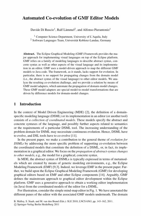
Automated Co-evolution of GMF Editor Models
Davide Di Ruscio1, Ralf Lammel2, and Alfonso Pierantonio1
1 Computer Science Department, University of L’Aquila, Italy2 Software Languages Team, Universitat Koblenz-Landau, Germany
Abstract. The Eclipse Graphical Modeling (GMF) Framework provides the ma-jor approach for implementing visual languages on top of the Eclipse platform.GMF relies on a family of modeling languages to describe abstract syntax, con-crete syntax as well as other aspects of the visual language and its implementa-tion in an editor. GMF uses a model-driven approach to map the different GMFmodels to Java code. The framework, as it stands, lacks support for evolution. Inparticular, there is no support for propagating changes from the domain model(i.e., the abstract syntax of the visual language) to other editor models. We ana-lyze the resulting co-evolution challenge, and we provide a solution by means ofGMF model adapters, which automate the propagation of domain-model changes.These GMF model adapters are special model-to-model transformations that aredriven by difference models for domain-model changes.
1 Introduction
In the context of Model Driven Engineering (MDE) [2], the definition of a domain-specific modeling language (DSML) or its implementation in an editor (or another tool)consists of a collection of coordinated models. These models specify the abstract andconcrete syntaxes of the language, and possibly further aspects related to semanticsor the requirements of a particular DSML tool. The increasing understanding of theproblem domain for DSML may necessitate continuous evolution. Hence, DSML haveto evolve, and DSL tools have to co-evolve [11].
In the present paper, we make a contribution to the general theme of evolution forDSMLs by addressing the more specific problem of supporting co-evolution betweenthe coordinated models that constitute the definition of a DSML, or, in fact, its imple-mentation in a graphical editor. We focus on the propagation of abstract-syntax changesto other models, e.g., the model for a graphical, concrete syntax.
In MDE, the abstract syntax of DSMLs is typically expressed in terms of metamod-els which are created by means of generic modeling environments, e.g., the EclipseModeling Framework (EMF) [9,3]. Indeed, we leverage EMF in the present paper. Fur-ther, we build upon the Eclipse Graphical Modeling Framework (GMF) for developinggraphical editors based on EMF and other Eclipse components [14]. Arguably, GMFdefines the mainstream approach to graphical editor development within the Eclipseplatform. GMF uses a generative approach to obtain a working editor implementation(in Java) from the coordinated models of the editor for a DSML.
For illustration, consider the simple mind-map editor in Fig. 1. We have annotated thedifferent panes of the editor with the associated GMF models underneath. The domain
B. Malloy, S. Staab, and M. van den Brand (Eds.): SLE 2010, LNCS 6563, pp. 143–162, 2011.c© Springer-Verlag Berlin Heidelberg 2011

144 D. Di Ruscio, R. Lammel, and A. Pierantonio
Fig. 1. Snapshot of a simple editor with indications of underlying models
model is concerned with the abstract syntax. The graphical and the tooling definitionare concerned with concrete syntax and the editor functionality. The mapping modelconnects the various models. We will describe the architecture of the editor in moredetail later. In the GMF approach, model-to-model and model-to-code transformationsderive the implementation of a graphical editor which provides the means for editingmodels conforming to the specified domain model.
With such a multi-model and generative approach to editor implementation, changesto the abstract syntax (i.e., the metamodel) invalidate instances (i.e., models), other edi-tor models, generated code, and all model transformations that may depend on the afore-mentioned models. In previous work, the problem of metamodel/model co-evolutionhas been addressed [4,29], but the problem of co-evolution among coordinated editormodels is largely unexplored. The present paper specifically contributes to this openproblem, which helps with the co-evolution of DSML editors as opposed to the co-evolution of pre-existing DSML models. More specifically, we are concerned with thequestions what and how GMF models need to be co-changed in reply to changes ofthe domain model (say, metamodel, or abstract syntax definition) of the editor. The co-evolution challenge at hand is to adapt GMF editors when changes are operated on thedomain model.
The GMF framework does not support such co-evolution, and this somewhat dimin-ishes the original goal of GMF to aggressively simplify the development of graphicaleditors. That is, while it is reasonable simple to draft and connect all GMF models fromscratch, it is notably difficult to evolve an editor through changes of specific GMF mod-els. A recurring focus for evolution is the domain model of the editor. When the domainmodel is changed, the user may notice that the editor has to be fixed through unsuccess-ful runs of some generator, the compiler, or the editor itself, and in all cases, subjectto error messages at a low level of abstraction. Alternatively, the user may attempt toregenerate some models through the available wizards (model-to-model transforma-tions of GMF), which however means that the original, possibly customized models arelost.
Automated Co-evolution of GMF Editor Models 145
The complexity of the co-evolution problem for DSML editors has been recognizedalso by others (e.g., see [20,27]). Also, in [27], the authors discuss that the GMF in-frastructure has a number of limitations, some of them related to co-evolution, and theyeven propose an alternative solution to define graphical editors for modeling languages.Even outside the MDE context, the identified co-evolution challenge is relevant, and ithas not been generally addressed. For instance, in compiler construction and domain-specific language implementation for languages with textual syntax, the same kind ofbreaking changes to abstract or concrete syntaxes can happen, and not even the mostadvanced transformation- or mapping-based approaches to the coordination of the syn-taxes readily address the challenge (e.g., see [18,30]). The challenge is only exacerbatedby the multiplicity of coordinated models in an approach for DSML editors such as withGMF.
The contributions of the paper can be summarized as follows:
– We analyze GMF’s characteristics in terms of the co-evolution of the various mod-els that contribute to a GMF editor. Starting from conceived domain-modelchanges, their implications for the editor itself and other GMF models areidentified.
– Even though catalogues for metamodel changes are available from multiple exist-ing works (e.g., [4,28,29]—to mention a few), the application of such a changecatalogue to a different scenario (i.e., the editor models in a “dependency” relation)is a novelty.
– We address the resulting co-evolution challenge by complementing GMF’s wizard-and generator-biased architecture with GMF adapters, which are model-to-modeltransformations that propagate changes of the domain model to other models.
– The GMF adapters leverage on a difference model which is used to represent differ-ences between subsequent versions of a given metamodel. Such difference modelshave been used in previous works on co-evolution, but the illustration of their ap-plicability to the new kind of co-evolution challenge at hand is an important steptowards their promotion to a general MDE technique.
We make available some reusable elements of our development publicly (scenarios,transformations, difference models, etc.)1.
Road-map of the paper
In Sec. 2, we recall the basics of the GMF approach to graphical editor development,and we clarify GMF’s use of a collection of coordinated editor models. In Sec. 3, westudy a detailed evolution scenario to analyse the co-evolution challenge at hand. InSec. 4, we develop an initial list of domain model changes and derive a methodology ofco-evolution based on propagating changes to all relevant GMF models. In Sec. 5, wedescribe a principled approach for the automation of the required co-evolution transfor-mation based on the interpretation of difference models for the domain-model changes.In Sec. 6, we sketch a proof-of-concept implementation that is also available online.Related work is described in Sec. 7, and the paper is concluded in Sec. 8.
1 http://www.emfmigrate.org/gmfevolution

146 D. Di Ruscio, R. Lammel, and A. Pierantonio
Create GMF Project
Develop DomainModel
Develop GraphicalModel
Develop ToolingModel
Develop MappingModel
Create GeneratorModel
Generate DiagramPlug-in
Fig. 2. The model-driven approach to GMF-based editor development
2 GMF’s Coordinated Editor Models
GMF consists of a generative component (GMF Tooling) and runtime infrastructure(GMF Runtime) for developing graphical editors based on the Eclipse Modeling Frame-work (EMF) [9,3] and the Graphical Editing Framework (GEF) [12]. The GMF Toolingsupports a model-driven process (see Fig. 2) for generating a fully functional graphicaleditor based on the GMF Runtime starting from the following models:
– The domain model is the Ecore-based metamodel (say, abstract syntax) of the lan-guage for which representation and editing have to be provided.
– The graphical definition model contains part of the concrete syntax; it identifiesgraphical elements that may, in fact, be reused for different editors.
– The tooling definition model contains another part of the concrete syntax; it con-tributes to palettes, menus, toolbars, and other periphery of the editor.
– Conceptually, the aforementioned models are reusable; they do not contain refer-ences to each other. It is the mapping model that establishes all links.
Consider again Fig. 1 which illustrates the role of these models for a simple mind-mapeditor.2 Fig. 3 shows all the models involved in the definition and implementation ofthe mind-map editor. The rectangular boxes highlight contributions that are related tothe Topic domain concept. It is worth noting how information about domain concepts isscattered over the various models. Most of these recurrences are not remote since mostof the correspondences are name-based. Remote references are only to be found in themapping and the generator models as clarified in the rest of the work.
Domain model. This model contains all the concepts and relationships which haveto be implemented in the editor. In the example, the class Mindmap is introduced as acontainer of instances of the classes Topic and Relation.
Graphical definition model. This model specifies a figure gallery including shapes,labels, lines, etc., and canvas elements to define nodes, connections, compartments,and diagram labels. For instance, in the graphical model in Fig. 3, a rectangle named
2 A mind map is a diagram used to represent words, ideas, tasks, or other items linked to andarranged around a central keyword or idea. The initial mind-map editor suffices with “topics”and “relations”, but some extensions will be applied eventually.
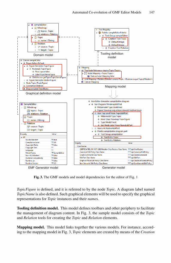
Automated Co-evolution of GMF Editor Models 147
Domain model
Generator model
Tooling definitionmodel
Graphical definition model
Mapping model
EMF Generator model
Fig. 3. The GMF models and model dependencies for the editor of Fig. 1
TopicFigure is defined, and it is referred to by the node Topic. A diagram label namedTopicName is also defined. Such graphical elements will be used to specify the graphicalrepresentations for Topic instances and their names.
Tooling definition model. This model defines toolbars and other periphery to facilitatethe management of diagram content. In Fig. 3, the sample model consists of the Topicand Relation tools for creating the Topic and Relation elements.
Mapping model. This model links together the various models. For instance, accord-ing to the mapping model in Fig. 3, Topic elements are created by means of the Creation

148 D. Di Ruscio, R. Lammel, and A. Pierantonio
Tool Topic and the graphical representation for them is Node Topic. For each topic thecorresponding name is also visualized because of the specified Feature Label Mappingwhich relates the attribute name of the class Topic with the diagram label TopicNamedefined in the graphical definition model. The meaning of the false value near the Fea-ture Label Mapping element is that the attribute name is not read-only, thus it will befreely edited by the user.
EMF and GMF generator models. Once a domain model is defined, it is possibleto automatically produce Java code to manage models (instances), say mind maps inour example. To this end an additional model, the EMF generator model, is required tocontrol the execution of the EMF generator. A uniform version of the extra model canbe generated by EMF tooling.
Once the mapping model is obtained, the GMF Tooling generates (by means of amodel-to-model transformation) the GMF generator model that is used by a code gen-erator to produce the real code of the modeled graphical editor.
3 GMF’s Co-evolution Challenge
Using a compound change scenario, we will now demonstrate GMF’s co-evolution chal-lenges. We will describe how domain-model changes break other editor models, and theeditor’s code, or make them unsound otherwise. Hence, domain-model changes mustbe propagated. Such change propagation is not supported currently by GMF, and it islabor-intensive and error-prone, when carried out manually. Conceptually, it turns outto be difficult to precisely predict when and how co-changes must be performed.
Fig. 4. An evolved mind-map editor with different kinds of topics

Automated Co-evolution of GMF Editor Models 149
(a) New version of the sample metamodel
(b) Dangling references in the GMF mapping model
Fig. 5. The domain model for the evolved mind-map editor with the “broken” mapping model
3.1 A Compound Change Scenario
Consider the enhanced mind-map editor of Fig. 4. Compared to the initial version ofFig. 1, scientific vs. literature topics are distinguished, and topics have a duration prop-erty in addition to the name property.
Now consider Fig. 5; it shows the evolved metamodel at the top, and the status ofthe, as yet, unamended mapping model at the bottom. We actually show the mappingmodel as it would appear to the user if it was inspected in Eclipse. Some of the links inthe mapping model are no longer valid; in fact, they are dangling (c.f., “null”). Throughextra edges, we show what the links are supposed to be like.
We get a deeper insight into the situation if we comprehend the evolved domainmodel through a series of simple, potentially atomic changes:
1. The Topic class was renamed to ScientificTopic.2. The abstract class NamedElement was added.3. The attribute name is pulled up from the Topic class to the NamedElement class.4. The attribute duration was added to the NamedElement class.5. The class LiteratureTopic was added as a further specialization of NamedElement.
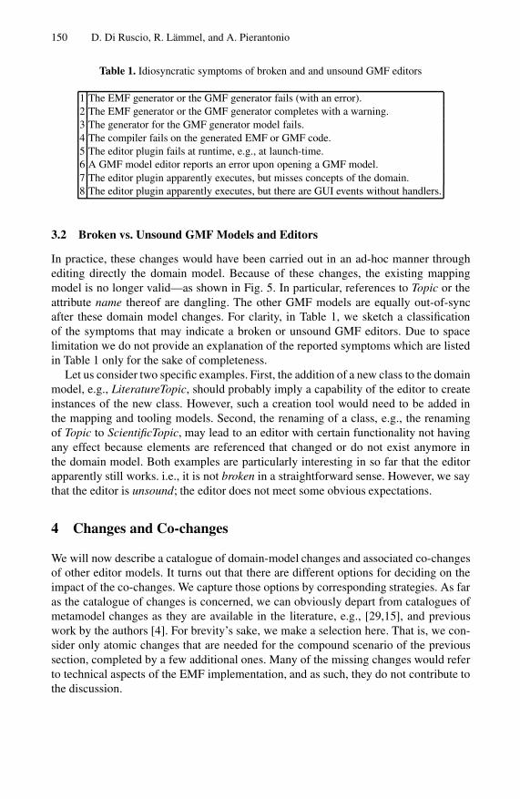
150 D. Di Ruscio, R. Lammel, and A. Pierantonio
Table 1. Idiosyncratic symptoms of broken and and unsound GMF editors
1 The EMF generator or the GMF generator fails (with an error).2 The EMF generator or the GMF generator completes with a warning.3 The generator for the GMF generator model fails.4 The compiler fails on the generated EMF or GMF code.5 The editor plugin fails at runtime, e.g., at launch-time.6 A GMF model editor reports an error upon opening a GMF model.7 The editor plugin apparently executes, but misses concepts of the domain.8 The editor plugin apparently executes, but there are GUI events without handlers.
3.2 Broken vs. Unsound GMF Models and Editors
In practice, these changes would have been carried out in an ad-hoc manner throughediting directly the domain model. Because of these changes, the existing mappingmodel is no longer valid—as shown in Fig. 5. In particular, references to Topic or theattribute name thereof are dangling. The other GMF models are equally out-of-syncafter these domain model changes. For clarity, in Table 1, we sketch a classificationof the symptoms that may indicate a broken or unsound GMF editors. Due to spacelimitation we do not provide an explanation of the reported symptoms which are listedin Table 1 only for the sake of completeness.
Let us consider two specific examples. First, the addition of a new class to the domainmodel, e.g., LiteratureTopic, should probably imply a capability of the editor to createinstances of the new class. However, such a creation tool would need to be added inthe mapping and tooling models. Second, the renaming of a class, e.g., the renamingof Topic to ScientificTopic, may lead to an editor with certain functionality not havingany effect because elements are referenced that changed or do not exist anymore inthe domain model. Both examples are particularly interesting in so far that the editorapparently still works. i.e., it is not broken in a straightforward sense. However, we saythat the editor is unsound; the editor does not meet some obvious expectations.
4 Changes and Co-changes
We will now describe a catalogue of domain-model changes and associated co-changesof other editor models. It turns out that there are different options for deciding on theimpact of the co-changes. We capture those options by corresponding strategies. As faras the catalogue of changes is concerned, we can obviously depart from catalogues ofmetamodel changes as they are available in the literature, e.g., [29,15], and previouswork by the authors [4]. For brevity’s sake, we make a selection here. That is, we con-sider only atomic changes that are needed for the compound scenario of the previoussection, completed by a few additional ones. Many of the missing changes would referto technical aspects of the EMF implementation, and as such, they do not contribute tothe discussion.

Automated Co-evolution of GMF Editor Models 151
Table 2. Levels of editor soundness along evolution.
Level Description
1 Unsound in the sense of being broken; there are reported issues (errors, warnings).2 Unsound in the sense that the editor “obviously” lacks capabilities.3 Sound as far as it can be achieved through automated transformations.4 Sound; established by human evaluation.
4.1 Strategies for Co-changes
Such a distinction of broken vs. not broken but nevertheless unsound also naturallyrelates to a spectrum of strategies for co-changes. A minimalistic strategy would focuson fixing the broken editor. That is, co-changes are supposed to bring the editor modelsto a state where no issues are reported at generation, compile or runtime. A best-effortstrategy would try to bring the editor to a sound state, or as close to it as possible witha general (perhaps automated) strategy.
Consider again the example of adding a new class C:
Minimalistic strategy. The execution of the EMF generator emits a warning, whichwe take to mean that the editor is broken. Hence, we would add the new class C tothe EMF generator model. This small co-change would be sufficient to re-executeall generators without further errors or warnings, and to build and run the editorsuccessfully. The editor would be agnostic to the new class though because themapping and tooling models were not co-changed.
Best-effort strategy. Let us make further assumptions about the added class C. In fact,let us assume that C is a concrete class, and it has a superclass S with at leastone existing concrete subclass D. In such a case, we may co-change the other GMFmodels by providing management for C based on the replication of the managementfor D.
Here we assume that a best-effort strategy may be amenable to an automated transfor-mation approach in that it does not require any domain-specific insight. The modelerwill still need to perform additional changes to complete the evolution, i.e., to obtain asound editor.
4.2 Editor Soundness Related to Co-changes
In continuation of the soundness discussion from the previous section, Table 2 identifiesdifferent levels of soundness for an evolving editor. The idea here is that we assess thelevel of the editor before and after all (automated) co-changes were applied. The pro-posed transformations can never reach Level 4 because it requires genuine evaluation bythe modeler. In other words, Level 4 refers to situations where GMF models can not beautomatically migrated and they have to be adapted by the modeler in order to supportall the modeling constructs defined in the new version of the considered metamodel.
However, we are not just interested in the overall level of the editor, but we also wantto blame one or more editor models for the editor’s unsoundness. In Table 3, we list

152 D. Di Ruscio, R. Lammel, and A. Pierantonio
Table 3. Considered Ecore metamodel changes
beforeco-change
afterco-change
EM
FG
en
Gra
ph
Tool
ing
Map
ping
Lev
el
EM
FG
en
Gra
ph
Tool
ing
Map
ping
Lev
el
Add empty, concrete class × ◦ ◦ ◦ 1 • ◦ ◦ ◦ 2Add empty, abstract class × • • • 1 • • • • 3Add specialization • • • • 3 • • • • 3Delete concrete class × ◦ × × 1 • ◦ • • 2Rename class × ◦ ◦ × 1 • • • • 3Add property × ◦ ◦ ◦ 1 • ◦ ◦ • 2Delete property × ◦ × × 1 • ◦ • • 2Rename property × ◦ ◦ × 1 • • • • 3Move property × ◦ × × 1 • ◦ ◦ ◦ 2Pull up property × ◦ × × 1 • ◦ • • 2Change property type • ◦ × × 1 • ◦ ◦ ◦ 2
atomic changes with the soundness levels for the editor before and after co-changes,and all the indications as to what models are to blame. We use “×” to blame a modelfor causing the editor to be broken, i.e., to be at Level 1. We use “◦” and “•” likewisefor Level 2 and Level 3.
The EMFGen model is frequently to blame for a broken editor before the co-changes;the Graph model is never to blame for a broken editor; the remaining models are toblame occasionally for a broken editor. Obviously, there is trend towards less blame af-ter the co-changes: no occurrences of “×”, more occurrences of “•”. In different terms,for all domain-model changes, all other models can be co-changed so that the editor isno longer broken. In several cases, we reach Level 3 for the editor.
There are clearly constellations for which changes cannot be propagated in an au-tomated manner that resolves all Level 2 blame. For instance, the metamodel changeadd empty, concrete class does not require a co-changed Graph model as long as someexisting graphical element can be reused. However, avoidance of Level 2 blame wouldrequire a manual designation of a new element or genuine selection of a specific elementas opposed to an automatically chosen element.
4.3 Specific Couples of Changes and Co-changes
In the rest of the section, the changes reported in Table 3 and the corresponding co-changes, which have to be operated on the GMF models, are described in more detail.
Add empty, concrete class. Apart from the EMFGen model, the other ones are not af-fected; the editor simply does not take into account the added class. Thus, modelerscannot create or edit instances of the new class. The co-change may replicate the modelfrom existing classes as discussed in Sec. 3. Ultimately, the modeler may need to man-ually complete the management of the new class.

Automated Co-evolution of GMF Editor Models 153
Add empty, abstract class. In comparison to the previous case, the co-change of theEMFGen model is fully sufficient since abstract classes cannot be instantiated, andhence, no additional functionality is needed in the editor.
Add specialization. The change consists of modifying an existing class by specifying itas specialization of another one. In particular, in the simple case of the superclass beingempty, this modification does not affect any model; thus, no co-changes are required.
Delete concrete class. Deleting an existing class is more problematic since all the GMFmodels except the Graph model are affected. Especially the Mapping model has to befixed to solve possible dangling references to the deleted class. The Tooling model isalso co-changed by removing the creation tool used to create instances of the deletedclass. Even if the model is not adapted, the generator model and thus the editor canbe generated—even though the palette will contain a useless tool without associatedfunctionality. The Graph model can be left unchanged. The graphical elements whichwere used for representing instances of the deleted class, may be re-used in the future.
Rename class. Renaming a class requires co-change of the Mapping model which canhave, as in the case of class deletion, invalid references which have to be fixed byconsidering the new class name. The Graph model does not require any co-changesince the graphical elements used for the old class can be used even after the renameoperation. The Tooling model can be left untouched, or alternatively the label and thedescription of the tool related to the renamed class can be modified to reflect the samename. However, even with the same Tooling model, a working editor will be generated.
Add property. The strategy for co-change is similar to the addition of new classes.
Delete property. Deleting a property which has a diagrammatic representation requires aco-change of the Mapping model in order to fix occurred dangling references. Moreoverif some tools were available to manage the deleted property, also the Tooling model hasto be co-changed. As in the case of class removals, the graphical model can be leftunchanged.
Rename property. The strategy for co-change is similar to the renaming of classes.
Move property. When a property is moved from one class to another, then danglingreferences may need to be resolved in the Mapping model. If the moved property ismanaged by means of some tools, the Tooling model require co-changes, too. We onlyoffer a simple, generic strategy for co-changes: the repaired editor does not consider themoved property.
Pull up property. Given a class hierarchy, a given property is moved from an extended toa base class. This modification is similar to the previous one—even though an automaticresolution can be provided to co-change Tooling and Mapping models in a satisfactorymanner.
Change property type. The EMFGen model is not affected. However, by changing thetype of a property some dangling references can occur in the Mapping model; theirresolution cannot be fully automated. Also, if the affected property is managed by sometool, then the Tooling model must be co-changed as well.

154 D. Di Ruscio, R. Lammel, and A. Pierantonio
Domain model 1
Domain model 2
DifferenceCalculation Difference model
EMFGenadapter
GMFTooladapter
GMFMapadapter
EMFGen model GMFTool model GMFMap model
AdaptedEMFGen model
AdaptedGMFTool model
AdaptedGMFMap model
Fig. 6. Overview of the process of co-evolution with automated transformations
5 Automated Adaptation of GMF Models
Having a catalogue of changes like the one previously discussed is preparatory for sup-porting the adaptation of GMF models. In particular, it can be exploited to automaticallydetect the modifications that have been operated on a given domain model, and to in-struct corresponding migration procedures as proposed in the rest of the paper.
We have developed a general process for GMF co-evolution which involves modeldifferencing techniques and automated transformations to adapt existing GMF modelswith respect to the changes operated on domain models. The approach is described inFig. 6 and consists of the following elements:
– Difference calculation, given two versions of the same domain model, their differ-ences are calculated to identify the changes which have been operated on the firstversion of the model to obtain the last one. The calculation can be operated byany of the existing approaches able to detect the differences between any kind ofmodels, like EMFCompare [7];
– Difference representation, the detected differences have to be represented in a waywhich is amenable to automatic manipulations and analysis. To take advantageof standard model driven technologies, the calculated differences should be rep-resented by means of another model;
– Generation of the adapted GMF models, the differences represented in the differ-ence model are taken as input by specific adapters each devoted to the adaptation ofa given GMF model with respect to the metamodel modifications and correspond-ing co-changes reported in Table 3. In particular, the GMFMap and the GMFTooladapters are devoted to the adaptation of the GMFMap model and the GMFToolmodel, respectively. Such adapters take both models because of dependencies be-tween them which have to be updated simultaneously. The EMFGen model is up-dated by means of a specific adapters, whereas no adapter is provided for the Graphmodel. In fact, the discussion of the previous sections suggested that we can alwaysreasonable continue with the old Graph model. The adapters can be implementedas model transformations which take as input the old version of the GMF modelsand produce the adapted ones.

Automated Co-evolution of GMF Editor Models 155
Model
DifferenceMetamodel(MMD)
MM2MMDtransformation
EcoreMetamodel
Metamodel(MM)
conformsTo
M3
M2 Difference Model(MD)
conformsTo
detected in
conformsTo
induces
MC
AddedMC
DeletedMC
ChangedMC updatedElement
1..*
Fig. 7. Difference metamodel generation
Interestingly, the process in Fig. 6 is independent from the technologies which havebeen adopted both for calculating and managing domain model differences, and to au-tomatically manipulate them for generating the adapted GMF models.
6 Proof-of-Concept Implementation of the GMF Adapters
In this section we propose the support for the GMF model adaptation approach wedescribed in the previous section. That is, in Sec. 6.1, we outline a technique for rep-resenting the differences between two versions of a same metamodel. Such a represen-tation approach has been already used by the authors for managing other co-evolutionproblems [4]. Further, in Sec. 6.2, the ATL transformation language [17] is adopted forimplementing the different model adapters which have been identified to evolve existingGMF models. The implementation of the approach is available publicly as described inthe introduction of the paper.
6.1 Model-Based Representation of Domain Model Differences
The differences between different versions of a same domain model can be representedby exploiting the difference metamodel concept, presented by the authors in [5]. The ap-proach is summarized in Fig. 7: given two Ecore metamodels, their difference conformsto a difference metamodel MMD derived from Ecore by means of the MM2MMD trans-formation. For each class MC of the Ecore metamodel, the additional classes AddedMC,DeletedMC, and ChangedMC are generated in the extended Ecore metamodel by en-abling the representation of the possible modifications that can occur on domain modelsand that can be grouped as follows:
– additions, new elements are added in the initial metamodel;– deletions, some of the existing elements are deleted;– changes, some of the existing elements are updated.
In Fig. 8, a fragment of the difference model representing the changes between the do-main models in Fig. 3 and Fig. 5 is shown. Such a difference model conforms to a differ-ence metamodel automatically obtained from the ECore metamodel. Forinstance, from the metaclass EClass of the ECore metamodel, the metaclasses AddedE-Class, DeletedEClass, and ChangedEClass are generated in the corresponding differ-ence metamodel.

156 D. Di Ruscio, R. Lammel, and A. Pierantonio
Fig. 8. Fragment of the difference model for the evolution scenario of Sec. 3
For some of the reported differences in Fig. 8, the corresponding properties areshown. For instance, the renaming of the Topic class is represented by means of aChangedEClass instance which has as updated element an instance of EClass namedLiteratureTopic (see the updatedElement property of the changed class Topic shown onthe right-hand side of Fig. 8). The addition of the class NamedElement is represented bymeans of an AddedEClass instance. The move operation of the attribute name from theclass Topic to the added class NamedElement is represented by means of a ChangedEAt-tribute instance which has one EAttribute instance as updated element with a differentvalue for the eContainingClass property. In fact, in the initial version it was Topic (seethe second property window) whereas in the last one, it is NamedElement (as specifiedin the third property window).
6.2 ATL-Based Implementation of GMF Model Adapters
Our prototypical implementation of the GMF model adapters leverages ATL [17], aQVT [24] compliant language which contains a mixture of declarative and imperativeconstructs. In particular, each model adapter is implemented in terms of model trans-formations which use a common query library described in rest of the section.
An ATL transformation consists of a module specification containing a header sec-tion (e.g. lines 1-3 in Listing 1.1), transformation rules (lines 5-42 in Listing 1.1) anda number of helpers which are used to navigate models and to define complex calcula-tions on them (some helpers which have been implemented are described in Table 4). Inparticular, the header specifies the source models, the corresponding metamodels, andthe target ones; the helpers and the rules are the constructs used to specify the transfor-mation behaviour.
Small excerpts of the GMFMap and GMFTool adapters are shown in Listing 1.1 andListing 1.2, respectively. For instance, the AddedSpecializationClassTo... transforma-tion rules manage new classes which have been added in the domain model as special-izations of an existing one. The code excerpts involve the replication strategy that wehave described in previous sections.
ATL transformation rules consist of source and target patterns: the former consist ofsource types and an OCL [25] guard stating the elements to be matched; the latter are

Automated Co-evolution of GMF Editor Models 157
Table 4. Some helpers of the gmfAdaptationLib
Helper name Context Return type DescriptiongetEClassInNewMetamodel EClass EClass Given a class of the old metamodel, it re-
turns the corresponding one in the newmetamodel.
getNewContainer EAttribute EClass Given an EAttribute in the old metamodel,the corresponding container in the newone is retrieved. To this end, the helperchecks if the EAttribute has been movedto a new added class, if not an existingclass is returned.
isMoved EAttribute Boolean It checks if the considered EAttribute hasbeen moved to another container
isMovedToAddedEClass EAttribute Boolean It checks if the considered EAttribute hasbeen moved to a new added EClass.
isRenamed EAttribute Boolean It checks if the given EAttribute has beenrenamed.
composed of a set of elements, each of them specifies a target type from the target meta-model and a set of bindings. A binding refers to a feature of the type, i.e. an attribute, areference or an association end, and specifies an expression whose value initializes thefeature. For instance, the AddedSpecializationClassToNodeMapping rule in Listing 1.1is executed for each match of the source pattern in lines 8-17 which describes situationslike the one we had in the sample scenario where the LiteratureTopic class (see s1) isadded as specialization of an abstract class (see s2) which is specialized by another class(see s3). In this case, the Mapping model is updated by adding a new TopNodeReferenceand its contained elements (see lines 24-41) which are copies of those already existingfor s3.
A similar source pattern is used in the rule of Listing 1.2 (lines 7-12) in order to adda creation tool for the new added class s1 to the Tooling model (see lines 19-23).
1module GMFMapAdapter;2create OUT : GMFMAPMM from IN : GMFMAPMM, GMFTOOL: GMFTOOLMM, DELTA: DELTAMM,3 NEWECORE : ECORE, OLDECORE : ECORE ;4...5rule AddedSpecializationClassToNodeMapping {67 from8 s1: DELTAMM!AddedEClass, s2: DELTAMM!AddedEClass,9 s3: DELTAMM!ChangedEClass, s4: DELTAMM!ChangedEAttribute,
10 s5: DELTAMM!EAttribute11 ((not s1.abstract)12 and s1.eSuperTypes->first() = s213 and s2.abstract14 and s3.updatedElement->first().eSuperTypes->first() = s215 and s4.updatedElement->first() = s516 and s4.eContainingClass = s317 and s5.eContainingClass = s2 ))1819 using {20 siblingFeatureLabelMapping : GMFMAPMM!FeatureLabelMapping =

158 D. Di Ruscio, R. Lammel, and A. Pierantonio
21 s3.getNodeMappingFromChangedClass().labelMappings22 ->select(e | e.oclIsTypeOf(GMFMAPMM!FeatureLabelMapping))->first()
; }2324 to25 t1 : GMFMAPMM!TopNodeReference (26 containmentFeature <- s3.getTopNodeReferenceFromChangedClass().27 containmentFeature.getFeatureInNewMetamodel(),28 ownedChild <- t229 ),30 t2 : GMFMAPMM!NodeMapping (31 domainMetaElement <- s1.getAddedClassInNewMetamodel(),32 relatedDiagrams <- s3.getNodeMappingFromChangedClass().relatedDiagrams,33 tool <- s1.name.getNewToolFromTitle(),34 diagramNode <- s3.getNodeMappingFromChangedClass().diagramNode35 ),36 t3 : GMFMAPMM!FeatureLabelMapping (37 diagramLabel <- siblingFeatureLabelMapping.diagramLabel,38 features <- siblingFeatureLabelMapping.features->collect(e |39 e.getFeatureInNewMetamodel())40 ),41 ...42}
Listing 1.1. Fragment of the GMFMap Adapter
To summarize, the implementation of the GMF adapters consists of transformationrules which copy the given source model to a target one; during this operation theyevaluate if changes are needed. A number of helpers have been defined; they navigatemodels and perform complex queries on them. Many of the helpers are common to allthe adapters, and hence, they are available through a library gmfAdaptationLib. Table 4describes some of these helpers.
1module GMFToolAdapter;2create OUT : GMFTOOLMM from IN : GMFTOOLMM, GMFMAP : GMFMAPMM, DELTA: DELTAMM,3 NEWECORE : ECORE, OLDECORE : ECORE ;4...5rule AddedSpecializationClassToCreationTool {67 from8 s1: DELTAMM!AddedEClass, s2: DELTAMM!AddedEClass, s3: DELTAMM!ChangedEClass9 ( (not s1.abstract)
10 and s1.eSuperTypes->first() = s211 and s2.abstract12 and s3.updatedElement->first().eSuperTypes->first() = s2 )1314 using {15 toolGroup : GMFTOOLMM!ToolGroup = OclUndefined;16 }1718 to19 t : GMFTOOLMM!CreationTool (20 title <- s3.getToolFromChangedClass().title.regexReplaceAll(s3.21 getToolFromChangedClass().title, s1.name),22 description <- ’Create new ’ + s1.name23 ),24 ...25}
Listing 1.2. Sample transformation rule of the GMFTool Adapter
Automated Co-evolution of GMF Editor Models 159
7 Related Work
7.1 Graphical Model Editors
In [1], a number of technologies for the development of domain-specific modeling lan-guages (DSMLs) are evaluated; Eclipse (EMF with GEF) is covered, but not GMF. Theevaluation criteria include language evolution to mean the ability to co-evolve modelswhen the domain model changes. There is no criterion though that relates to GMF’sparticular characteristics of using multiple editor models.
Other GMF- or GEF-based frameworks have been proposed. For instance, the Muvi-torKit framework [23] is based on EMF and GEF and specifically meant as an alterna-tive to GMF for the benefit of additional editor capabilities (e.g., multiple panes) as wellas additional modeling capabilities, thereby requiring less customization of generatedcode. There is also the EuGENia framework [20,19] which raises the level of abstrac-tion in GMF-based development by using annotations on the domain model, therebyfeeding into code generation. We are not aware of any prior effort to propagate changesacross GMF models.
The ViatraDSM framework [27] replaces GMF in that it allows for versatilemappings between abstract and concrete syntax. Live transformations are leveragedto maintain the coherence of the two models. Our uni-directional, difference-driventransformations propagate domain-model changes elsewhere. Our work is specificallytargeted at the mainstream GMF-based approach with its various models.
7.2 Model Consistency
The status of GMF models being out-of-sync can be compared to the notion of modelinconsistency in (UML-based) modeling where different models providing differentviews may require synchronization. For instance, in [8], inconsistencies between thedifferent diagrammatic forms in UML models are considered, and possible fixes areproposed in the form of value changes. In [13], the dependencies between models aremodeled through triple graph grammars in a manner that enables incremental modelsynchronization. Our specific contribution is one of reverse engineering: discovering theGMF model dependencies, and making them operational through automatedtransformations.
7.3 Co-evolution of Metamodels and Models
The techniques and the methodology of our work are inspired by research on co-evolution in model-driven engineering [10,28]. Much of this work is concerned withco-transforming models in reply to metamodel changes [29,15]. In that case metamodelchanges can invalid existing models that have to be adapted to recover the conformancewith the new version of the metamodel.
In this work, we analyze another kind of co-evolution, even though related to theprevious one, which aims at propagating metamodel changes to the other GMF modelsaccording to a given soundness level of the editor. The overall proposal leverages thedifference representation approach proposed by the authors in [5] and already used tomanage co-evolution problems in [6].

160 D. Di Ruscio, R. Lammel, and A. Pierantonio
7.4 Syntax Relationships for Textual Languages
In [18,30,26], approaches for the operationalization of the link between concrete andabstract syntax definition are described. That is, concrete syntax definitions are cus-tomized into abstract syntax definitions. In fact, the approach of [18] is based on theidea that concrete and abstract syntax definitions can be incomplete but they automat-ically complete each other based on name mapping and other heuristics. In contrast,the approach of [30] is based on grammar transformations where the concrete syntaxis mapped operationally to the abstract syntax. In [26], yet another approach is exer-cised, where the abstract syntax definition is associated with the concrete syntax defini-tion through annotations. (A similar MDE approach is the one of TCS for KM3 [16].)None of these approaches provides any automated capabilities for change propagation.The classical approach to concrete-to-abstract syntax mappings is to use an attributegrammar. There are a number of approaches to align grammar transformations with at-tribution transformations, see, e.g., [21,22], but none of these approaches are directlyapplicable to the synchronization of abstract and concrete syntax. We contend that theproblem of collections of coordinated GMF editor models seems to be even more com-plicated than concrete/abstract syntax synchronization.
8 Concluding Remarks
We have described the challenge of sound evolution for graphical editors based onmodel-driven development with GMF in particular, and we have addressed this chal-lenge by a system of co-transformations that propagate changes from domain modelsto the other editor models.
We have identified a range of options for evolved editors to be unsound, and we havedescribed corresponding resolution strategies. In the more established area of meta-model/model co-evolution, models either are not broken, or they are broken and canbe reasonably resolved in an automated manner, or a well-understood problem-specificcontribution to the resolution must be provided manually or through a heuristic. In thecase of co-evolution for editor models, there is a scale of models being broken or un-sound. Also, each of the various models calls for a designated analysis. Finally, thereare intricate inter-model dependencies.
The existing GMF infrastructure is obviously rather complicated: it consists of anumber of metamodels, libraries, generators, model transformations of industrial scale.We cannot claim to provide a full-fledged solution to the co-evolution challenge ofGMF—this would require full coverage of Ecore, the metamodeling language of EMF,and full understanding of the implicit semantics of GMF model dependencies and tools.
The focus of this paper is on the conceptual co-evolution challenge at hand. The de-velopment of industrial-strength tools for co-evolution or the revision of the GMF suiteis a clearly a major undertaking that is beyond the scope of this paper. The prototypicalimplementation of the proposed approach supports all the metamodel changes reportedin Table 3. Nevertheless, we are confident that our transformational approach can bescaled incrementally over time to cover an increasing number of concrete evolutionscenarios. In the future we plan to support them by providing additional effort in theimplementation of the overall approach. The most critical omission in our methodology
Automated Co-evolution of GMF Editor Models 161
is that we do not currently cover co-evolution of custom code. This is a very intricateproblem by itself, to which we hope to contribute through future work.
In our ongoing research, we try to better understand the co-evolution issues andassociated strategies for the code level of GMF where generated code has been possiblycustomized. Based on preliminary research, we can already report that customizationis used by some GMF projects extensively, and hence designated co-evolution supportmay provide significant help with real-world editor development.
References
1. Amyot, D., Farah, H., Roy, J.-F.: Evaluation of Development Tools for Domain-SpecificModeling Languages. In: Gotzhein, R., Reed, R. (eds.) SAM 2006. LNCS, vol. 4320, pp.183–197. Springer, Heidelberg (2006)
2. Bezivin, J.: On the Unification Power of Models. Jour. on Software and Systems Modeling(SoSyM) 4(2), 171–188 (2005)
3. Budinsky, F., Steinberg, D., Merks, E., Ellersick, R., Grose, T.: Eclipse Modeling Framework.Addison-Wesley, Reading (2003)
4. Cicchetti, A., Di Ruscio, D., Eramo, R., Pierantonio, A.: Automating Co-evolution in Model-Driven Engineering. In: Proceedings of the 12th International IEEE Enterprise DistributedObject Computing Conference, ECOC 2008, pp. 222–231. IEEE Computer Society, LosAlamitos (2008)
5. Cicchetti, A., Di Ruscio, D., Pierantonio, A.: A Metamodel Independent Approach to Differ-ence Representation. Journal of Object Technology 6(9), 165–185 (2007)
6. Cicchetti, A., Di Ruscio, D., Pierantonio, A.: Model Patches in Model-Driven Engineering.In: Ghosh, S. (ed.) MODELS 2009. LNCS, vol. 6002, pp. 190–204. Springer, Heidelberg(2010)
7. Eclipse Foundation. EMF Compare (2010),http://www.eclipse.org/modeling/emft/?project=compare
8. Egyed, A., Letier, E., Finkelstein, A.: Generating and Evaluating Choices for Fixing Inconsis-tencies in UML Design Models. In: 23rd IEEE/ACM International Conference on AutomatedSoftware Engineering (ASE 2008), pp. 99–108. IEEE, Los Alamitos (2008)
9. Eclipse project: Eclipse Modeling Framework Project (EMF),http://www.eclipse.org/modeling/emf/
10. Favre, J.-M.: Meta-Model and Model Co-evolution within the 3D Software Space. In: Pro-ceedings of International Workshop on Evolution of Large-scale Industrial Software Ap-plications (ELISA 2003), Co-located with the IEEE International Conference on SoftwareMaintenance, ICSM 2003 (2003)
11. Favre, J.-M.: Languages Evolve Too! Changing the Software Time Scale. In: IEEE (ed.) 8thInterntational Workshop on Principles of Software Evolution, IWPSE (2005)
12. Eclipse project: GEF - Graphical Editing Framework,http://www.eclipse.org/gef/
13. Giese, H., Wagner, R.: Incremental Model Synchronization with Triple Graph Grammars.In: Wang, J., Whittle, J., Harel, D., Reggio, G. (eds.) MoDELS 2006. LNCS, vol. 4199, pp.543–557. Springer, Heidelberg (2006)
14. Eclipse project: GMF - Graphical Modeling Framework,http://www.eclipse.org/gmf/
15. Herrmannsdoerfer, M., Benz, S., Jurgens, E.: COPE - Automating Coupled Evolution ofMetamodels and Models. In: Drossopoulou, S. (ed.) ECOOP 2009. LNCS, vol. 5653, pp.52–76. Springer, Heidelberg (2009)

162 D. Di Ruscio, R. Lammel, and A. Pierantonio
16. Jouault, F., Bezivin, J., Kurtev, I.: TCS: a DSL for the specification of textual concrete syn-taxes in model engineering. In: Proceedings of Generative Programming and ComponentEngineering (GPCE 2006), pp. 249–254. ACM, New York (2006)
17. Jouault, F., Kurtev, I.: Transforming Models with ATL. In: Bruel, J.-M. (ed.) MoDELS 2005.LNCS, vol. 3844, pp. 128–138. Springer, Heidelberg (2006)
18. Kadhim, B., Waite, W.: Maptool—supporting modular syntax development. In: Gyimothy,T. (ed.) CC 1996. LNCS, vol. 1060, pp. 268–280. Springer, Heidelberg (1996)
19. Kolovos, D.S., Rose, L.M., Abid, S.B., Paige, R.F., Botterweck, G.: Taming EMF andGMF Using Model Transformation. In: 13th ACM/IEEE International Conference on ModelDriven Engineering, Languages and Systems, MoDELS (to appear, 2010)
20. Kolovos, D.S., Rose, L.M., Paige, R.F., Polack, F.A.C.: Raising the level of abstraction inthe development of GMF-based graphical model editors. In: MISE 2009: Proceedings of the2009 ICSE Workshop on Modeling in Software Engineering, pp. 13–19. IEEE, Los Alamitos(2009)
21. Lammel, R., Riedewald, G.: Reconstruction of paradigm shifts. In: Proceedings of the Sec-ond Workshop on Attribute Grammars and their Applications (WAGA 1999), pp. 37–56(March 1999); INRIA Technical Report ISBN 2-7261-1138-6
22. Lohmann, W., Riedewald, G., Stoy, M.: Semantics-preserving migration of semantic rulesafter left recursion removal in attribute grammars. In: Proceedings of 4th Workshop on Lan-guage Descriptions, Tools and Applications (LDTA 2004). ENTCS, vol. 110, pp. 133–148.Elsevier Science, Amsterdam (2004)
23. Modica, T., Biermann, E., Ermel, C.: An Eclipse Framework for Rapid Development of Rich-featured GEF Editors based on EMF Models. In: Proceedings of Informatik 2009: Im Focusdas Leben, Beitrage der 39. Jahrestagung der Gesellschaft fuur Informatik e.V (GI). LNI,vol. 154, pp. 2972–2985. GI (2009)
24. Object Management Group (OMG). MOF QVT Final Adopted Specification, OMG AdoptedSpecification ptc/05-11-01 (2005)
25. Object Management Group (OMG). OCL 2.0 Specification, OMG Document formal/2006-05-01 (2006)
26. Overbey, J.L., Johnson, R.E.: Generating Rewritable Abstract Syntax Trees. In: Gasevic,D., Lammel, R., Van Wyk, E. (eds.) SLE 2008. LNCS, vol. 5452, pp. 114–133. Springer,Heidelberg (2009)
27. Rath, I., Okros, A., Varro, D.: Synchronization of abstract and concrete syntax in domain-specific modeling languages—By mapping models and live transformations. Journal of Soft-ware and Systems Modeling (2009)
28. Vermolen, S., Visser, E.: Heterogeneous Coupled Evolution of Software Languages. In:Busch, C., Ober, I., Bruel, J.-M., Uhl, A., Volter, M. (eds.) MODELS 2008. LNCS, vol. 5301,pp. 630–644. Springer, Heidelberg (2008)
29. Wachsmuth, G.: Metamodel Adaptation and Model Co-adaptation. In: Bateni, M. (ed.)ECOOP 2007. LNCS, vol. 4609, pp. 600–624. Springer, Heidelberg (2007)
30. Wile, D.: Abstract syntax from concrete syntax. In: Proceedings, International Conferenceon Software Engineering (ICSE 1997), pp. 472–480. ACM Press, New York (1997)

An Extensive Catalog of Operators for the
Coupled Evolution of Metamodels and Models
Markus Herrmannsdoerfer1, Sander D. Vermolen2, and Guido Wachsmuth2
1 Institut fur Informatik,Technische Universitat Munchen
Boltzmannstr. 3, 85748 Garching b. Munchen, [email protected]
2 Software Engineering Research Group,Delft University of Technology
The Netherlands{S.D.Vermolen,G.H.Wachsmuth}@tudelft.nl
Abstract. Modeling languages and thus their metamodels are subjectto change. When a metamodel is evolved, existing models may no longerconform to it. Manual migration of these models in response to meta-model evolution is tedious and error-prone. To significantly automatemodel migration, operator-based approaches provide reusable coupledoperators that encapsulate both metamodel evolution and model migra-tion. The success of an operator-based approach highly depends on thelibrary of reusable coupled operators it provides. In this paper, we thuspresent an extensive catalog of coupled operators that is based both on aliterature survey as well as real-life case studies. The catalog is organizedaccording to a number of criteria to ease assessing the impact on modelsas well as selecting the right operator for a metamodel change at hand.
1 Introduction
Like software, modeling languages are subject to evolution due to changing re-quirements and technological progress [9]. A modeling language is adapted to thechanged requirements by evolving its metamodel. Due to metamodel evolution,existing models may no longer conform to the evolved metamodel and thus needto be migrated to reestablish conformance to the evolved metamodel. Avoidingmodel migration by downwards-compatible metamodel changes is often a poorsolution, since it reduces the quality of the metamodel and thus the modelinglanguage [5]. Manual migration of models is tedious and error-prone, and hencemodel migration needs to be automated. In coupled evolution of metamodelsand models, the association of a model migration to a metamodel evolutionis managed automatically. There are two major coupled evolution approaches:difference-based and operator-based approaches.
Difference-based approaches use a declarative evolution specification, gener-ally referred to as difference model [6,11]. The difference model is mapped ontoa model migration, which may be specified declaratively as well as imperatively.
B. Malloy, S. Staab, and M. van den Brand (Eds.): SLE 2010, LNCS 6563, pp. 163–182, 2011.c© Springer-Verlag Berlin Heidelberg 2011

164 M. Herrmannsdoerfer, S.D. Vermolen, and G. Wachsmuth
Operator-based approaches specify metamodel evolution by a sequence of op-erator applications [24,13]. Each operator application can be coupled to a modelmigration separately. Operator-based approaches generally provide a set of re-usable coupled operators which work at the metamodel level as well as at themodel level. At the metamodel level, a coupled operator defines a metamodeltransformation capturing a common evolution. At the model level, a coupledoperator defines a model transformation capturing the corresponding migration.Application of a coupled operator to a metamodel and a conforming model pre-serves model conformance.
In both operator-based and difference-based approaches, evolution can bespecified manually [24], can be recorded [13], or can be detected automati-cally [6,11]. When recording, the user is restricted to a recording editor. Usingautomated detection, the building process can be completely automated, butmay lead to an incorrect model migration.
In this paper, we follow an operator-based approach to automate buildinga model migration for EMOF-like metamodels [18]. The success of an opera-tor-based approach highly depends on the library of reusable coupled operatorsit provides [20]. The library of an operator-based approach needs to fulfill anumber of requirements. A library should seek completeness so as to be ableto cover a large set of evolution scenarios. However, the higher the number ofcoupled operators, the more difficult it is to find a coupled operator in the library.Consequently, a library should also be organized in a way that it is easy to selectthe right coupled operator for the change at hand.
To provide guidance for building a library, we present an extensive catalog ofcoupled operators in this paper. To ensure completeness, the coupled operatorsin this catalog are either motivated from the literature or from case studies thatwe performed. However, we do not target theoretical completeness—to captureall possible migrations—but rather practical completeness—to capture migra-tions that likely happen in practice. To ease usability, the catalog is organizedaccording to a number of criteria. The criteria do not only allow to select theright coupled operator from the catalog, but also to assess the impact of thecoupled operator on the modeling language and its models. For difference-basedapproaches, the catalog serves as a set of composite changes that such an ap-proach needs to be able to handle.
The paper is structured as follows: Section 2 presents the EMOF-like meta-modeling formalism on which the coupled operators are based. Section 3 intro-duces the papers and case studies from which the coupled operators originate.Section 4 defines different classification criteria for coupled operators. Section 5lists and groups the coupled operators of the catalog. Section 6 discusses thecatalog, and Section 7 concludes the paper.
2 Metamodeling Formalism
Metamodels can be expressed in various metamodeling formalisms. Well-knownexamples are the Meta Object Facility (MOF) [18], the metamodeling standard

Catalog of Operators for the Coupled Evolution of Metamodels and Models 165
proposed by the Object Management Group (OMG) and Ecore [21], the meta-modeling formalism underlying the Eclipse Modeling Framework (EMF). In thispaper, we focus only on the core metamodeling constructs that are interestingfor coupled evolution of metamodels and models. We leave out annotations, de-rived features, and operations, since these cannot be instantiated in models. Anoperator catalog will need additional operators addressing these metamodelingconstructs in order to reach full compatibility with Ecore or MOF.
Metamodel. Figure 1 gives a textual definition of the metamodeling formalismused in this paper. A metamodel is organized into Packages which can themselvesbe composed of sub packages. Each package defines a number of Types which canbe either primitive (PrimitiveType) or complex (Class). Primitive types are eitherDataTypes like Boolean, Integer and String or Enumerations of literals. Classesconsist of a number of features. They can have super types to inherit features andmight be abstract, i.e. are not allowed to have objects. The name of a featureneeds to be unique among all features of a class, including inherited ones. A Fea-ture has a multiplicity (lower bound and upper bound) and is either an Attributeor a Reference. An attribute is a feature with a primitive type, whereas a refer-ence is a feature with a complex type. An attribute can serve as an identifier forobjects of a class, i.e. the values of this attribute must be unique among all ob-jects. A reference may be composite and two references can be combined to forma bidirectional association by making them opposite of each other.
abstract class NamedElement {name :: String (1..1)
}
class Package : NamedElement {subPackages <> Package (0..∗)types <> Type (0..∗)
}
abstract class Type : NamedElement {}
abstract class PrimitiveType : Type {}
class DataType : PrimitiveType {}
class Enumeration : PrimitiveType {literals <> Literal (0..∗)
}
class Literal : NamedElement {}
class Class : Type {isAbstract :: BooleansuperTypes −> Class (0..∗)features <> Feature (0..∗)
}
abstract class Feature : NamedElement {lowerBound :: IntegerupperBound :: Integertype −> Type
}
class Attribute : Feature {isId :: Boolean
}
class Reference : Feature {isComposite :: Booleanopposite −> Reference
}
Fig. 1. Metamodeling formalism providing core metamodeling concepts
Model. At the model level, instances of classes are called objects, instancesof primitive data types are called values, instances of features are called slots,and instances of references are called links. The set of all links of compositereferences forms a containment structure, which needs to be tree-shaped andspan all objects in a model.

166 M. Herrmannsdoerfer, S.D. Vermolen, and G. Wachsmuth
Notational Conventions. Throughout the paper, we use the textual notationfrom Figure 1 for metamodels. In this notation, features are represented bytheir name followed by a separator, their type, and an optional multiplicity.The separator indicates the kind of a feature. We use :: for attributes, -> forordinary references, and <> for composite references.
3 Origins of Coupled Operators
The coupled operators are either motivated from the literature or from casestudies that we performed.
Literature. First, coupled operators originate from the literature on the evo-lution of metamodels as well as object-oriented database schemas and code.
Wachsmuth first proposes an operator-based approach for metamodel evolu-tion and classifies a set of operators according to the preservation of metamodelexpressiveness and existing models [24]. Gruschko et al. envision a difference-based approach and therefore classify all primitive changes according to theirimpact on existing models [2,4]. Cicchetti et al. list a set of composite changeswhich they are able to detect using their difference-based approach [6].
Banerjee et al. present a complete and sound set of primitives for schemaevolution in the object-oriented database system ORION and characterize theprimitives according to their impact on existing databases [1]. Breche introducesa set of high-level operators for schema evolution in the object-oriented systemO2 and shows how to implement them in terms of primitive operators [3]. Ponsand Keller propose a three-level catalog of operators for object-oriented schemaevolution which groups operators according to their complexity [19]. Claypoolet al. list a number of primitives for the adaptation of relationships in object-oriented systems [7].
Fowler presents a catalog of operators for the refactoring of object-orientedcode [10]. Dig and Johnson show—by performing a case study—that most chan-ges on object-oriented code can be captured by a rather small set of refactoringoperators [8].
Case Studies. Second, coupled operators originate from a number of case stud-ies that we have performed. Table 1 gives an overview over these case studies.It mentions the tool that was used in a case study, the name of the evolvingmetamodel, an abbreviation for the case study which we use in other tablesthroughout the paper, and whether the evolution was obtained in a forward orreverse engineering process. In forward engineering, the tool is used to aid andpossibly record evolution as it happens, whereas in reverse engineering, the toolis used to reconstruct evolution after it occurred. To provide evidence that thecase studies are considerable in size, the table also shows the number of differentkinds of metamodel elements at the end of the evolution as well as the numberof operator applications needed to perform the evolution.

Catalog of Operators for the Coupled Evolution of Metamodels and Models 167
Table 1. Statistics for case studies
Tool Abbreviation Name Kind Pac
kage
s
Cla
sses
Att
ribu
tes
Ref
eren
ces
Dat
aT
ypes
Enu
mer
atio
ns
Liter
als
Ope
rato
rA
pplic
atio
ns
[12]F FLUID
reverse8 155 95 155 0 1 10 223
T TAF-Gen 15 97 81 114 1 13 76 134
COPE
[13] PCMreverse
19 99 18 135 0 4 19 101[14] GMF 4 252 379 278 0 27 166 737U Unicase forward 17 77 88 161 0 11 49 58Q Quamoco 1 22 14 35 0 1 2 423
AcodaB BugZilla reverse – 51 208 64 – – – 237R Researchr forward – 125 380 278 – 6 31 64Y YellowGrass – 12 33 21 – 0 0 30
Herrmannsdoerfer et al. performed a case study on the evolution of two indus-trial metamodels to show that most of the changes can be captured by reusablecoupled operators [12]: Flexible User Interface Development (FLUID) for thespecification of automotive user interfaces and Test Automation Framework -Generator (TAF-Gen) for the generation of test cases for these user interfaces.
Based on the requirements derived from this study, Herrmannsdoerfer imple-mented the operator-based tool COPE1 [13] which records operator historieson metamodels of the Eclipse Modeling Framework (EMF). To demonstrate itsapplicability, COPE has been used to reverse engineer the operator history of anumber of metamodels: Palladio Component Model (PCM) for the specificationof software architectures [13] and Graphical Modeling Framework (GMF) for themodel-based development of diagram editors [14]. Currently, COPE is appliedto forward engineer the operator history of a number of metamodels: Unicase2
for UML modeling and project management and Quamoco3 for modeling thequality of software products.
Vermolen implemented the operator-based tool Acoda4 [22] which detects op-erator histories on object-oriented data models. To demonstrate its applicabil-ity, Acoda has been used to reverse engineer the operator history of the datamodel behind BugZilla which is a well-known tool for bug tracking. Currently,Acoda is applied to forward engineer the operator-based evolution of a numberof data models: Researchr5 for maintaining scientific publications and Yellow-Grass6 for tag-based issue tracking. The crossed-out cells in Table 1 indicate
1 COPE web site, http://cope.in.tum.de2 Unicase web site, http://unicase.org3 Quamoco web site, http://www.quamoco.de4 Acoda web site, http://swerl.tudelft.nl/bin/view/Acoda5 Researchr web site, http://researchr.org6 YellowGrass web site, http://yellowgrass.org

168 M. Herrmannsdoerfer, S.D. Vermolen, and G. Wachsmuth
that the metamodeling constructs are currently not supported by the used datamodeling formalism.
4 Classification of Coupled Operators
Coupled operators can be classified according to several properties. We are inter-ested in language preservation, model preservation, and bidirectionality. There-fore, we stick to a simplified version of the terminology from [24].
Language Preservation. A metamodel is an intensional definition of a lan-guage. Its extension is a set of conforming models. When an operator is appliedto a metamodel, this has an impact on its extension and thus on the expres-siveness of the language. We distinguish different classes of operators accordingto this impact [15,24]: An operator is a refactoring if there exists always a bi-jective mapping between extensions of the original and the evolved metamodel.An operator is a constructor if there exists always an injective mapping fromthe extension of the original metamodel to the extension of the evolved meta-model. An operator is a destructor if there exists always a surjective mappingfrom the extension of the original metamodel to the extension of the evolvedmetamodel.
Model Preservation. Model preservation properties indicate when migrationis needed. An operator is model-preserving if all models conforming to an origi-nal metamodel also conform to the evolved metamodel. Thus, model-preservingoperators do not require migration. An operator is model-migrating if modelsconforming to an original metamodel might need to be migrated in order toconform to the evolved metamodel. It is safely model-migrating if the migra-tion preserves distinguishability, i.e. different models (conforming to the originalmetamodel) are migrated to different models (conforming to the evolved meta-model). In contrast, an unsafely model-migrating operator might yield the samemodel when migrating two different models.
Classification of operators w.r.t. model preservation is related to the classi-fication w.r.t. language preservation: Refactorings and constructors are eithermodel-preserving or safely model-migrating operators. Destructors are unsafelymodel-migrating operators. Furthermore, the classification is related to a classifi-cation of changes known from difference-based approaches [2,4]: model-preservingoperators perform non-breaking changes, whereas model-migrating operatorsperform breaking, resolvable changes. However, there is no correspondence forbreaking, non-resolvable changes, since coupled operators always provide a mi-gration to resolve the breaking change.
Bidirectionality. Another property we are interested in is the reversibilityof evolution. Bidirectionality properties indicate that an operator can be safely

Catalog of Operators for the Coupled Evolution of Metamodels and Models 169
undone on the language or model level. An operator is self-inverse iff a secondapplication of the operator—possibly with other parameters—always yields theoriginal metamodel. An operator is the inverse of another operator iff there isalways a sequential composition of both operators which does not change themetamodel. Finally, an operator is a safe inverse of another operator iff it is aninverse and there is always a sequential composition of both operators which ismodel-preserving.
5 Catalog of Coupled Operators
In this section, we present a catalog of 61 coupled operators that we considercomplete for practical application. As discussed in Section 3, we included allcoupled operators found in nine related papers as well as all coupled operatorsidentified by performing nine real-life case studies. In the following, we explainthe coupled operators in groups which help users to navigate the catalog. Westart with primitive operators which perform an atomic metamodel evolutionstep that can not be further subdivided. Here, we distinguish structural primi-tives which create and delete metamodel elements and non-structural primitiveswhich modify existing metamodel elements. Afterwards, we continue with com-plex operators. These can be decomposed into a sequence of primitive opera-tors which has the same effect at the metamodel level but not neccessarily atthe model level. We group complex operators according to the metamodelingtechniques they address—distinguishing specialization and generalization, del-egation, and inheritance operators—as well as their semantics—distinguishingreplacement, and merge and split operators.
Each group is discussed separately in the subsequent sections. For each group,a table provides an overview over all operators in the group. Using the classi-fications from Section 4, the table classifies each coupled operator according tolanguage preservation (L) into refactoring (r), constructor (c) and destructor (d)as well as according to model preservation (M) into model-preserving (p), safely(s) and unsafely (u) model-migrating. The table further indicates the safe (s)and unsafe (u) inverse (I) of each operator by referring to its number. Finally,each paper and case study has a column in each table. An x in such a columndenotes occurrence of the operator in the corresponding paper or case study.Papers are referred to by citation, while case studies are referred to by the ab-breviation given in Table 1. For each coupled operator, we discuss its semanticsin terms of metamodel evolution and model migration.
5.1 Structural Primitives
Structural primitive operators modify the structure of a metamodel, i.e. cre-ate or delete metamodel elements. Creation operators are parameterized by thespecification of a new metamodel element, and deletion operators by an existingmetamodel element.

170 M. Herrmannsdoerfer, S.D. Vermolen, and G. Wachsmuth
Class. MM OODB OOC [12] COPE Acoda
# Operator Name L M I [24] [2] [6] [1] [3] [19] [7] [10] [8] F T [13] [14] U Q B R Y
1 Create Package r p 2s x x x
2 Delete Package r p 1s x x
3 Create Class c p 4s x x x x x x x x x x x x x
4 Delete Class d u 3u x x x x x x x x x x x x
5 Create Attribute c s 7s x x x x x x x x x x x x x
6 Create Reference c s 7s x x x x x x x x x x x x x
7 Delete Feature d u 5/6u x x x x x x x x x x x x
8 Create Opposite Ref. d u 9u x x x x x x x x
9 Delete Opposite Ref. c p 8s x x x x
10 Create Data Type r p 11s x
11 Delete Data Type r p 10s x x
12 Create Enum r p 13s x x x x x x
13 Delete Enum r p 11s x x
14 Create Literal c p 15s x x
15 Merge Literal d u 14u x x
Creation of non-mandatory metamodel elements (packages, classes, optional fea-tures, enumerations, literals and data types) is model-preserving. Creation ofmandatory features is safely model-migrating. It requires initialization of slotsusing default values or default value computations.
Deleting metamodel elements, such as classes and references, requires delet-ing instantiating model elements, such as objects and links, by the migration.However, deletion of model elements poses the risk of migration to inconsistentmodels: For example, deletion of objects may cause links to non-existent objectsand deletion of references may break object containment. Therefore, deletion op-erators are bound to metamodel level restrictions: Packages may only be deletedwhen they are empty. Classes may only be deleted when they are outside inher-itance hierarchies and are targeted neither by non-composite references nor bymandatory composite references. Several complex operators discussed in subse-quent sections can deal with classes not meeting these requirements. Referencesmay only be deleted when they are neither composite, nor have an opposite.Enumerations and data types may only be deleted when they are not used inthe metamodel and thus obsolete.
Deletion operators which may have been instantiated in the model (with theexception of Delete Opposite Reference) are unsafely model-migrating due toloss of information. Deletion provides a safe inverse to its associated creationoperator. Since deletion of metamodel elements which may have been instanti-ated in a model is unsafely model-migrating, creation of such elements providesan unsafe inverse to deletion: Lost information cannot be restored.
Creating and deleting references which have an opposite are different fromother creation and deletion operators. Create Opposite Reference restricts theset of valid links and is thus an unsafely model-migrating destructor, whereasDelete Opposite Reference removes a constraint from the model and is thus amodel-preserving constructor.
Create / Delete Data Type and Create / Delete Enumeration are refactorings,as restrictions on these operators prevent usage of created or deleted elements.Deleting enumerations and data types is thus model-preserving. Merge Literal

Catalog of Operators for the Coupled Evolution of Metamodels and Models 171
deletes a literal and replaces its occurrences in a model by another literal. Merg-ing a literal provides a safe inverse to Create Literal.
5.2 Non-structural Primitives
Non-structural primitive operators modify a single, existing metamodel element,i.e. change properties of a metamodel element. All non-structural operators takethe affected metamodel element, their subject, as parameter.
Class. MM OODB OOC [12] COPE Acoda
# Operator Name L M I [24] [2] [6] [1] [3] [19] [7] [10] [8] F T [13] [14] U Q B R Y
1 Rename r s 1s x x x x x x x x x x x x x x x
2 Change Package r s 2s x x x x x
3 Make Class Abstract d u 4u x x x x
4 Drop Class Abstract c p 3s x x x
5 Add Super Type c p 6s x x x x x x x x x
6 Remove Super Type d u 5u x x x x x x x
7 Make Attr. Identifier d u 8u x x x
8 Drop Attr. Identifier c p 7s x x x
9 Make Ref. Composite d u 10u x x x x x x
10 Switch Ref. Composite c s 9s x x x x x x
11 Make Ref. Opposite d u 12u x x x x x
12 Drop Ref. Opposite c p 11s x x x x
Change Package can be applied to both package and type. Additionally, thevalue-changing operators Rename, Change Package and Change Attribute Typeare parameterized by a new value. Make Class Abstract requires a subclass pa-rameter indicating to which class objects need to be migrated. Switch ReferenceComposite requires an existing composite reference as target.
Packages, types, features and literals can be renamed. Rename is safely model-migrating and finds a self-inverse in giving a subject its original name back.Change Package changes the parent package of a package or type. Like renaming,it is safely model-migrating and a safe self-inverse.
Classes can be made abstract, requiring migration of objects to a subclass,because otherwise, links targeting the objects may have to be removed. Conse-quently, mandatory features that are not available in the super class have to beinitialized to default values. Make Class Abstract is unsafely model-migrating,due to loss of type information and has an unsafe inverse in Drop Class Ab-stract. Super type declarations may become obsolete and may need to be re-moved. Remove Super Type S from a class C implies removing slots of featuresinherited from S. Additionally, references targeting type S, referring to objectsof type C, need to be removed. To prevent breaking multiplicity restrictions, Re-move Super Type is restricted to types S which are not targeted by mandatoryreferences—neither directly, nor through inheritance. The operator is unsafelymodel-migrating and can be unsafely inverted by Add Super Type.
Attributes defined as identifier need to be unique. Make Attribute Identifierrequires a migration which ensures uniqueness of the attribute’s values and isthus unsafely model-migrating. Drop Attribute Identifier is model-preserving anddoes not require migration.

172 M. Herrmannsdoerfer, S.D. Vermolen, and G. Wachsmuth
References can have an opposite and can be composite. An opposite referencedeclaration defines the inverse of the declaring reference. References combinedwith a multiplicity restriction on the opposite reference restrict the set of validlinks. Make Reference Opposite needs a migration to make the link set satisfy theadded multiplicity restriction. The operator is thereby unsafely model-migrating.Drop Reference Opposite removes cardinality constraints from the link set anddoes not require migration, thus being model-preserving.
Make Reference Composite ensures containment of referred objects. Since allreferred objects were already contained by another composite reference, all ob-jects must be copied. To ensure the containment restriction, copying has to berecursive across composite references (deep copy). Furthermore, to prevent cardi-nality failures on opposite references, there may be no opposite references to anyof the types of which objects are subject to deep copying. Switch Reference Com-posite changes the containment of objects to an existing composite reference. Ifobjects of a class A were originally contained in class B through composite refer-ence b, Switch Reference Composite changes containment of A objects to class C,when it is parameterized by reference b and a composite reference c in class C.After applying the operator, reference b is no longer composite. Switch ReferenceComposite provides an unsafe inverse to Make Reference Composite.
5.3 Specialization / Generalization Operators
Specializing a metamodel element reduces the set of possible models, whereasgeneralizing expands the set of possible models. Generalization and specializationcan be applied to features and super type declarations. All specialization andgeneralization operators take two parameters: a subject and a generalization orspecialization target. The first is a metamodel element and the latter is a classor a multiplicity (lower and upper bound).
Class. MM OODB OOC [12] COPE Acoda
# Operator Name L M I [24] [2] [6] [1] [3] [19] [7] [10] [8] F T [13] [14] U Q B R Y
1 Generalize Attribute c p 2s x x x x x x x x x x x
2 Specialize Attribute d u 1u x x x x x x x
3 Generalize Reference c p 4s x x x x x x x x x
4 Specialize Reference d u 3u x x x x x x x x
5 Specialize Composite Ref. d u 3u x x x
6 Generalize Super Type d u 7u x x x
7 Specialize Super Type c s 6s x x x x x x x
Generalization of features does not only generalize the feature itself, but alsogeneralizes the metamodel as a whole. Feature generalizations are thus model-preserving constructors. Generalizing a super type declaration may requireremoval of feature slots and is only unsafely model-migrating. Feature special-ization is a safe inverse of feature generalization. Due to the unsafe nature ofthe migration resulting from feature specialization, generalization provides anunsafe inverse to specialization. Super type generalization is an safe inverse ofsuper type specialization which is a unsafe inverse vice versa.

Catalog of Operators for the Coupled Evolution of Metamodels and Models 173
Specialize Attribute either reduces the attribute’s multiplicity or specializesthe attribute’s type. When reducing multiplicity, either the lower bound is in-creased or the upper bound is decreased. When specializing the type, a typeconversion maps the original set of values onto a new set of values conformingthe new attribute type. Specializing type conversions are surjective. GeneralizeAttribute extends the attribute’s multiplicity or generalizes the attribute’s type.Generalizing an attribute’s type involves an injective type conversion. Type con-versions are generally either implemented by transformations for each type to anintermediate format (e.g. by serialization) or by transformations for each com-bination of types. The latter is more elaborate to implement, yet less fragile.Most generalizing type conversions from type x to y have a specializing typeconversion from type y to x as safe inverse. Applying the composition vice versayields an unsafe inverse.
Similar to attributes, reference multiplicity can be specialized and general-ized. Specialize / Generalize Reference can additionally specialize or generalizethe type of a reference by choosing a sub type or super type of the originaltype, respectively. Model migration of reference specialization requires deletionof links not conforming the new reference type. Specialize Composite Reference isa special case of reference specialization at the metamodel level, which requirescontained objects to be migrated to the targeted subclass at the model level,to ensure composition restrictions. Specialize Composite Reference is unsafelymodel-migrating.
Super type declarations are commonly adapted, while refining a metamodel.Consider the following example, in which classes A, B and C are part of a linearinheritance structure and remain unadapted:
class A { }class B : A { f :: Integer (1..1) }class C : A { }
class A { }class B : A { f :: Integer (1..1) }class C : B { }
From left to right, Specialize Super Type changes a declaration of super type A
on class C to B, a sub type of A. Consequently, a mandatory feature f is inherited,which needs the creation of slots by the migration. In general, super type special-ization requires addition of feature slots which are declared mandatory by thenew super type. From right to left, Generalize Super Type changes a declarationof super type B on class C to A, a super type of B. In the new metamodel, featuref is no longer inherited in C. Slots of features which are no longer inherited needto be removed by the migration. Furthermore, links to objects of A that targetclass B, are no longer valid, since A is no longer a sub type of B. Therefore, theselinks need to be removed, if multiplicity restrictions allow, or adapted otherwise.
5.4 Inheritance Operators
Inheritance operators move features along the inheritance hierarchy. Most ofthem are well-known from refactoring object-oriented code [10]. There is alwaysa pair of a constructor and destructor, where the destructor is the safe inverseof the constructor, and the constructor is the unsafe inverse of the destructor.

174 M. Herrmannsdoerfer, S.D. Vermolen, and G. Wachsmuth
Class. MM OODB OOC [12] COPE Acoda
# Operator Name L M I [24] [2] [6] [1] [3] [19] [7] [10] [8] F T [13] [14] U Q B R Y
1 Pull up Feature c p 2s x x x x x x x x
2 Push down Feature d u 1u x x x x x x
3 Extract Super Class c p 4s x x x x x x x x x x x x
4 Inline Super Class d u 3u x x x x x x x x x
5 Fold Super Class c s 6s x x
6 Unfold Super Class d u 5u x x
7 Extract Sub Class c s 8s x x x x x
8 Inline Sub Class d u 7u x x x x
Pull up Feature is a constructor which moves a feature that occurs in all sub-classes of a class to the class itself. For migration, slots for the pulled up featureare added to objects of the class and filled with default values. The correspondingdestructor Push down Feature moves a feature from a class to all its subclasses.While objects of the subclasses stay unaltered, slots for the original feature mustbe removed from objects of the class itself.
Extract Super Class is a constructor which introduces a new class, makes itthe super class of a set of classes, and pulls up one or more features from theseclasses. The corresponding destructor Inline Super Class pushes all features ofa class into its subclasses and deletes the class afterwards. References to theclass are not allowed but can be generalized to a super class in a previous step.Objects of the class need to be migrated to objects of the subclasses. This mightrequire the addition of slots for features of the subclasses.
The constructor Fold Super Class is related to Extract Super Class. Here, thenew super class is not created but exists already. This existing class has a setof (possibly inherited) features. In another class, these features are defined aswell. The operator then removes these features and adds instead an inheritancerelation to the intended super class. In the same way, the destructor UnfoldSuper Class is related to Inline Super Class. This operator copies all features ofa super class into a subclass and removes the inheritance relation between bothclasses. Here is an example for both operators:
class A { f1 :: Integer }class B : A { f2 :: Integer }class C { f1 :: Integer
f2 :: Integerf3 :: Integer }
class A { f1 :: Integer }class B : A { f2 :: Integer }class C : B { f3 :: Integer }
From left to right, the super class B is folded from class C which includes all thefeatures of B. These features are removed from C, and B becomes a super classof C. From right to left, the super class B is unfolded into class C by copyingfeatures A.f1 and B.f2 to C. B is not longer a super class of C.
The constructor Extract Subclass introduces a new class, makes it the subclassof another, and pushes down one or more features from this class. Objects of theoriginal class must be converted to objects of the new class. The correspondingdestructor Inline Subclass pulls up all features from a subclass into its non-abstract super class and deletes the subclass afterwards. References to the classare not allowed but can be generalized to a super class in a previous step. Objectsof the subclass need to be migrated to objects of the super class.

Catalog of Operators for the Coupled Evolution of Metamodels and Models 175
5.5 Delegation Operators
Delegation operators move metamodel elements along compositions or ordinaryreferences. Most of the time, they come as pairs of corresponding refactoringsbeing safely inverse to each other.
Class. MM OODB OOC [12] COPE Acoda
# Operator Name L M I [24] [2] [6] [1] [3] [19] [7] [10] [8] F T [13] [14] U Q B R Y
1 Extract Class r s 2s x x x x x x x x x x x x
2 Inline Class r s 1s x x x x x x x x
3 Fold Class r s 4s x x x
4 Unfold Class r s 3s
5 Move Feature over Ref. c s 6s x x x x x x x x x
6 Collect Feature over Ref. d u 5u x x
Extract Class moves features to a new delegate class and adds a compositereference to the new class together with an opposite reference. During migration,an object of the delegate class is created for each object of the original class,slots for the moved features are moved to the new delegate object, and a linkto the delegate object is created. The corresponding Inline Class removes adelegate class and adds its features to the referring class. There must be noother references to the delegate class. On the model level, slots of objects of thedelegate class are moved to objects of the referring class. Objects of the delegateclass and links to them are deleted. The operators become a pair of constructorand destructor, if the composite reference has no opposite.
Fold and Unfold Class are quite similar to Extract and Inline Class. The onlydifference is, that the delegate class exists already and thus is not created ordeleted. The following example illustrates the difference:
class A { a1 :: Integera2 :: Booleanr1 −> B (1..1)r2 −> B (0..∗) }
class B { }class C { a1 :: Integer
r1 −> B (1..1) }
class A { c <> C (1..1)d <> D (1..1) opposite a }
class B { }class C { a1 :: Integer
r1 −> B (1..1) }class D { a2 :: Boolean
r2 −> B (0..∗)a −> A (1..1) opposite d }
From left to right, the features a1 and r1 of class A are folded to a compositereference A.c to class C which has exactly these two features. In contrast, thefeatures a2 and r2 of class A are extracted into a new delegate class D. Fromright to left, the composite reference A.c is unfolded which keeps C intact whileA.d is inlined which removes D.
Move Feature along Reference is a constructor which moves a feature over asingle-valued reference to a target class. Slots of the original feature must bemoved over links to objects of the target class. For objects of the target classwhich are not linked to an object of the source class, slots with default valuesmust be added. The destructor Collect Feature over Reference is a safe inverse ofthe last operator. It moves a feature backwards over a reference. The multiplicityof the feature might be altered during the move depending on the multiplicity ofthe reference. For optional and/or multi-valued references, the feature becomes

176 M. Herrmannsdoerfer, S.D. Vermolen, and G. Wachsmuth
optional respectively multi-valued, too. Slots of the feature must be moved overlinks from objects of the source class. If an object of the source class is not linkedfrom objects of the target class, slots of the original feature are removed. Hereis an example for both operators:
class A { f1 :: Integer (1..∗)r1 −> B (1..1)r2 −> C (0..∗) }
class B { }class C { f2 :: Integer (1..1) }
class A { f2 :: Integer (0..∗)r1 −> B (1..1)r2 −> C (0..∗) }
class B { f1 :: Integer (1..∗) }class C { }
From left to right, the feature A.f1 is moved along the reference A.r1 to classB. Furthermore, the feature C.f2 is collected over the reference A.r2 and endsup in class A. Since A.r2 is optional and multi-valued, A.f2 becomes optionaland multi-valued, too. From right to left, the feature B.f1 is collected over thereference A.r1. Its multiplicity stays unaltered. Note that there is no singleoperator for moving A.f2 to class C which makes Collect Feature over Referencein general uninvertible. For the special case of a single-valued reference, MoveFeature along Reference is an unsafe inverse.
5.6 Replacement Operators
Replacement operators replace one metamodeling construct by another, equiva-lent construct. Thus replacement operators typically are refactorings and safelymodel-migrating. With the exception of the last two operators, an operator toreplace the first construct by a second always comes with a safe inverse to replacethe second by the first, and vice versa.
Class. MM OODB OOC [12] COPE Acoda
# Operator Name L M I [24] [2] [6] [1] [3] [19] [7] [10] [8] F T [13] [14] U Q B R Y
1 Subclasses to Enum. r s 2s x
2 Enum. to Subclasses r s 1s x x
3 Reference to Class r s 4s x x x
4 Class to Reference r s 3s x x
5 Inheritance to Delegation r s 6s x x x x x
6 Delegation to Inheritance r s 5s x x
7 Reference to Identifier c s 8s x
8 Identifier to Reference d u 7u x x x x
To be more flexible, empty subclasses of a class can be replaced by an attributewhich has an enumeration as type, and vice versa. Subclasses to Enumerationdeletes all subclasses of the class and creates the attribute in the class as wellas the enumeration with a literal for each subclass. In a model, objects of acertain subclass are migrated to the super class, setting the attribute to thecorresponding literal. Thus, the class is required to be non-abstract and to haveonly empty subclasses without further subclasses. Enumeration to Subclassesdoes the inverse and replaces an enumeration attribute of a class by subclassesfor each literal. The following example demonstrates both directions:
class C { ... }class S1 : C {}class S2 : C {}
class C { e :: E ... }
enum E { s1, s2 }

Catalog of Operators for the Coupled Evolution of Metamodels and Models 177
From left to right, Subclasses to Enumeration replaces the subclasses S1 and S2 ofclass C by the new attribute C.e which has the enumeration E with literals s1 ands2 as type. In a model, objects of a subclass S1 are migrated to class C, settingthe attribute e to the appropriate literal s1. From right to left, Enumeration toSubclasses introduces a subclass to C for each literal of E. Next, it deletes theattribute C.e as well as the enumeration E. In a model, objects of class C aremigrated to a subclass according to the value of attribute e.
To be able to extend a reference with features, it can be replaced by a class,and vice versa. Reference to Class makes the reference composite and createsthe reference class as its new type. Single-valued references are created in thereference class to target the source and target class of the original reference. In amodel, links conforming to the reference are replaced by objects of the referenceclass, setting source and target reference appropriately. Class to Reference doesthe inverse and replaces the class by a reference. To not lose expressiveness, thereference class is required to define no features other than the source and targetreferences. The following example demonstrates both directions:
class S {r −> T (l..∗) ...
}
class S { r <> R (l..∗) ... }class R { s −> S (1..1) opposite r
t −> T (1..1) }
From left to right, Reference to Class retargets the reference S.r to a newreference class R. Source and target of the original reference can be accessedvia references R.s and R.t. In a model, links conforming to the reference r
are replaced by objects of the reference class R. From right to left, Class toReference removes the reference class R and retargets the reference S.r directlyto the target class T.
Inheriting features from a superclass can be replaced by delegating them tothe superclass, and vice versa. Inheritance to Delegation removes the inheritancerelationship to the superclass and creates a composite, mandatory single-valuedreference to the superclass. In a model, the slots of the features inherited fromthe superclass are extracted to a separate object of the super class. By removingthe super type relationship, links of references to the superclass are no longerallowed to target the original object, and thus have to be retargeted to theextracted object. Delegation to Inheritance does the inverse and replaces thedelegation to a class by an inheritance link to that class. The following exampledemonstrates both directions:
class C : S { ... } class C { s <> S (1..1), ... }
From left to right, Inheritance to Delegation replaces the inheritance link of classC to its superclass S by a composite, single-valued reference from C to S. In amodel, the slots of the features inherited from the super class S are extracted toa separate object of the super class. From right to left, Delegation to Inheritanceremoves the reference C.s and makes S a super class of C.
To decouple a reference, it can be replaced by an indirect reference usingan identifier, and vice versa. Reference to Identifier deletes the reference andcreates an attribute in the source class whose value refers to an id attribute in

178 M. Herrmannsdoerfer, S.D. Vermolen, and G. Wachsmuth
the target class. In a model, links of the reference are replaced by setting theattribute in the source object to the identifier of the target object. Identifier toReference does the inverse and replaces an indirect reference via identifier bya direct reference. Our metamodeling formalism does not provide a means toensure that there is a target object for each identifier used by a source object.Consequently, Reference to Identifier is a constructor and Identifier to Referencea destructor, thus being an exception in the group of replacement operators.
5.7 Merge / Split Operators
Merge operators merge several metamodel elements of the same type into a sin-gle element, whereas split operators split a metamodel element into several ele-ments of the same type. Consequently, merge operators typically are destructorsand split operators constructors. In general, each merge operator has an inversesplit operator. Split operators are more difficult to define, as they may requiremetamodel-specific information about how to split values. There are differentmerge and split operators for the different metamodeling constructs.
Class. MM OODB OOC [12] COPE Acoda
# Operator Name L M I [24] [2] [6] [1] [3] [19] [7] [10] [8] F T [13] [14] U Q B R Y
1 Merge Features d u x x x
2 Split Reference by Type r s 1s x
3 Merge Classes d u 4u x x x x x x
4 Split Class c p 3s
5 Merge Enumerations d u x
Merge Features merges a number of features defined in the same class into asingle feature. In the metamodel, the source features are deleted and the targetfeature is required to be general enough—through its type and multiplicity—so that the values of the other features can be fully moved to it in a model.Depending on the type of feature that is merged, a repeated application ofCreate Attribute or Create Reference provides an unsafe inverse. Split Referenceby Type splits a reference into references for each subclass of the type of theoriginal reference. In a model, each link instantiating the original reference ismoved to the corresponding target reference according to its type. If we requirethat the type of the reference is abstract, this operator is a refactoring and hasMerge Features as a safe inverse.
Merge Classes merges a number of sibling classes—i.e. classes sharing a com-mon superclass—into a single class. In the metamodel, the sibling classes aredeleted and their features are merged to the features of the target class accord-ing to name equality. Each of the sibling classes is required to define the samefeatures so that this operator is a destructor. In a model, objects of the siblingclasses are migrated to the new class. Split Class is an unsafe inverse and splitsa class into a number of classes. A function that maps each object of the sourceclass to one of the target classes needs to be provided to the migration.
Merge Enumerations merges a number of enumerations into a single enumer-ation. In the metamodel, the source enumerations are deleted and their literalsare merged to the literals of the target enumeration according to name equality.
Catalog of Operators for the Coupled Evolution of Metamodels and Models 179
Each of the source enumerations is required to define the same literals so thatthis operator is a destructor. Additionally, attributes that have the source enu-merations as type have to be retargeted to the target enumeration. In a model,the values of these attributes have to be migrated according to how literals aremerged. A repeated application of Create Enumeration provides a safe inverse.
6 Discussion
Completeness. At the metamodel level, an operator catalog is complete if anysource metamodel can be evolved to any target metamodel. This kind of com-pleteness is achieved by the catalog presented in the paper. An extreme strategywould be the following [1]: In a first step, the original metamodel needs to bediscarded. Therefore, we delete opposite references and features. Next, we deletedata types and enumerations and collapse inheritance hierarchies by inlining sub-classes. We can now delete the remaining classes. Finally, we delete packages.In a second step, the target metamodel is constructed from scratch by creatingpackages, enumerations, literals, data types, classes, attributes, and references.Inheritance hierarchies are constructed by extracting empty subclasses.
Completeness is much harder to achieve, when we take the model level intoaccount. Here, an operator catalog is complete if any model migration corre-sponding to an evolution from a source metamodel to a target model can beexpressed. In this sense, a complete catalog needs to provide a full-fledged modeltransformation language based on operators. A first useful restriction is Turingcompleteness. But reaching for this kind of completeness comes at the price ofusability. Given an existing operator, one can always think of a slightly differentoperator having the same effect on the metamodel level but a slightly differentmigration. But the higher the number of coupled operators, the more difficultit is to find an operator in the catalog. And with many similar operators, it ishard to decide which one to apply.
We therefore do not target theoretical completeness—to capture all possi-ble migrations—but rather practical completeness—to capture migrations thatlikely happen in practice. When we started our case studies, we found the set ofoperators from the literature rather incomplete. For each case study, we addedfrequently reoccurring operators to the catalog. The number of operators weadded to the catalog declined with every new case study, thus approaching astable catalog. Our latest studies revealed no new operators. Although, in mostcase studies, we found a few operators which were only applied once in a singlecase study. They were never reused in other case studies. Therefore, we decidednot to include them in the catalog.
We expect similar special cases in practical applications where only a fewevolution steps can not be modeled by operators from the catalog. These casescan effectively be handled by providing a means for overwriting a coupling [13]:The user can specify metamodel evolution by an operator application but over-writes the model migration for this particular application. This way, theoreticalcompleteness can still be achieved.

180 M. Herrmannsdoerfer, S.D. Vermolen, and G. Wachsmuth
Metamodeling Formalism. In this paper, we focus only on core metamod-eling constructs that are interesting for coupled evolution of metamodels andmodels. But a metamodel defines not only the abstract syntax of a modelinglanguage, but also an API to access models expressed in this language. For thispurpose, concrete metamodeling formalisms like Ecore or MOF provide meta-modeling constructs like interfaces, operations, derived features, volatile features,or annotations. An operator catalog will need additional operators addressingthese metamodeling constructs to reach full compatibility with Ecore or MOF.
These additional operators are relevant for practical completeness. In theGMF case study [14], we found 25% of the applied operators to address changesin the API. Most of these operators do not require migration. The only excep-tions were annotations containing constraints. An operator catalog accountingfor constraints needs to deal with two kinds of migrations: First, the constraintsneed migration when the metamodel evolves. Operators need to provide thismigration in addition to model migration. Second, evolving constraints mightinvalidate existing models and thus require model migration. Here, new coupledoperators for the evolution of constraints are needed.
Things become more complicated when it comes to CMOF [18]. Concepts likepackage merge, feature subsetting, and visibility affect the semantics of operatorsin the paper and additional operators are needed to deal with these concepts.For example, we would need four different kinds of Rename due to the packagemerge: 1) Renaming an element which is not involved in a merge neither beforenor after the renaming (Rename Element). 2) Renaming an element which isnot involved in a merge in order to include it into a merge (Include by Name).3) Renaming an element which is involved in a merge in order to exclude it fromthe merge (Exclude by Name). 4) Renaming all elements which are merged tothe same element (Rename Merged Element).
Tool Support. In operator-based tools, operators are usually made availableto the user through an operator browser [23,13]. Here, the organization of thecatalog into groups can help to find an operator for a change at hand. Thepreservation properties can be used to reason about the impact on languageexpressiveness and on existing models. In grammarware, similar operators havebeen successfully used in [16] to reason about relationships between differentversions of the Java grammar. To make the user aware of the impact on models,it can be shown by a traffic light in the browser: green for model-preserving,yellow for safely and red for unsafely model-migrating. Additionally, the oper-ator browser may have different modes for restricting the presented operatorsin order to guarantee language- and/or model-preservation properties. Bidirec-tionality can be used to invert an evolution that has been specified erroneouslyearlier. Recorded operator applications can be automatically undone with dif-ferent levels of safety by applying the inverse operators. Tools that support evo-lution detection should evade of destructors in favor of refactorings to increasethe preservation of information by the detected evolution.
Difference-based tools [6,11] need to be able to specify the mappings un-derlying the operators from the catalog. When they allow to specify complex

Catalog of Operators for the Coupled Evolution of Metamodels and Models 181
mappings, they could introduce means to specify the mappings of the opera-tors in a straightforward manner. Introducing such first class constructs reducesthe effort for specifying the migration. For instance, the declarative languagepresented in [17] provides patterns to specify recurrent mappings.
7 Conclusion
We presented a catalog of 61 operators for the coupled evolution of metamod-els and models. These so-called coupled operators evolve a metamodel and inresponse are able to automatically migrate existing models. The catalog coversnot only well-known operators from the literature, but also operators which haveproven useful in a number of case studies we performed. The catalog is basedon the widely used EMOF metamodeling formalism [18] which was stripped ofthe constructs that cannot be instantiated in models. When a new construct isadded to the metamodeling formalism, new operators have to be added to thecatalog: Primitive operators to create, delete and modify the construct as well ascomplex operators to perform more intricate evolutions involving the construct.The catalog not only serves as a basis for operator-based tools, but also fordifference-based tools. Operator-based tools need to provide an implementationof the presented operators. Difference-based tools need to be able to specify themappings underlying the presented operators.
Acknowledgments. The work of the first author was funded by the Ger-man Federal Ministry of Education and Research (BMBF), grants “SPES 2020,01IS08045A” and “Quamoco, 01IS08023B”. The work of the other authors wassupported by NWO/JACQUARD, project 638.001.610, MoDSE: Model-DrivenSoftware Evolution.
References
1. Banerjee, J., Kim, W., Kim, H.J., Korth, H.F.: Semantics and implementationof schema evolution in object-oriented databases. SIGMOD Rec. 16(3), 311–322(1987)
2. Becker, S., Goldschmidt, T., Gruschko, B., Koziolek, H.: A process model and clas-sification scheme for semi-automatic meta-model evolution. In: Proc. 1st WorkshopMDD, SOA und IT-Management (MSI 2007), pp. 35–46. GiTO-Verlag (2007)
3. Breche, P.: Advanced primitives for changing schemas of object databases. In: Con-stantopoulos, P., Vassiliou, Y., Mylopoulos, J. (eds.) CAiSE 1996. LNCS, vol. 1080,pp. 476–495. Springer, Heidelberg (1996)
4. Burger, E., Gruschko, B.: A Change Metamodel for the Evolution of MOF-BasedMetamodels. In: Modellierung 2010. GI-LNI, vol. P-161 (2010)
5. Casais, E.: Managing class evolution in object-oriented systems. In: Object-Oriented Software Composition, pp. 201–244. Prentice Hall, Englewood Cliffs(1995)
6. Cicchetti, A., Ruscio, D.D., Eramo, R., Pierantonio, A.: Automating co-evolutionin model-driven engineering. In: EDOC 2008: 12th International Enterprise Dis-tributed Object Computing Conference. IEEE, Los Alamitos (2008)

182 M. Herrmannsdoerfer, S.D. Vermolen, and G. Wachsmuth
7. Claypool, K.T., Rundensteiner, E.A., Heineman, G.T.: ROVER: A framework forthe evolution of relationships. In: Laender, A.H.F., Liddle, S.W., Storey, V.C. (eds.)ER 2000. LNCS, vol. 1920, pp. 893–917. Springer, Heidelberg (2000)
8. Dig, D., Johnson, R.: How do APIs evolve? a story of refactoring. J. Softw. Maint.Evol. 18(2), 83–107 (2006)
9. Favre, J.M.: Languages evolve too! changing the software time scale. In: IWPSE2005: 8th International Workshop on Principles of Software Evolution, pp. 33–42(2005)
10. Fowler, M.: Refactoring: improving the design of existing code. Addison-WesleyLongman Publishing Co., Inc., Amsterdam (1999)
11. Garces, K., Jouault, F., Cointe, P., Bezivin, J.: Managing model adaptation byprecise detection of metamodel changes. In: Paige, R.F., Hartman, A., Rensink, A.(eds.) ECMDA-FA 2009. LNCS, vol. 5562, pp. 34–49. Springer, Heidelberg (2009)
12. Herrmannsdoerfer, M., Benz, S., Juergens, E.: Automatability of coupled evolutionof metamodels and models in practice. In: Busch, C., Ober, I., Bruel, J.-M., Uhl,A., Volter, M. (eds.) MODELS 2008. LNCS, vol. 5301, pp. 645–659. Springer,Heidelberg (2008)
13. Herrmannsdoerfer, M., Benz, S., Juergens, E.: COPE - automating coupled evolu-tion of metamodels and models. In: Drossopoulou, S. (ed.) ECOOP 2009. LNCS,vol. 5653, pp. 52–76. Springer, Heidelberg (2009)
14. Herrmannsdoerfer, M., Ratiu, D., Wachsmuth, G.: Language evolution in practice:The history of GMF. In: van den Brand, M., Gasevic, D., Gray, J. (eds.) SLE 2009.LNCS, vol. 5969, pp. 3–22. Springer, Heidelberg (2010)
15. Lammel, R.: Grammar adaptation. In: Oliveira, J.N., Zave, P. (eds.) FME 2001.LNCS, vol. 2021, pp. 550–570. Springer, Heidelberg (2001)
16. Lammel, R., Zaytsev, V.: Recovering grammar relationships for the Java languagespecification. In: SCAM 2009: Ninth IEEE International Working Conference onSource Code Analysis and Manipulation, pp. 178–186. IEEE, Los Alamitos (2009)
17. Narayanan, A., Levendovszky, T., Balasubramanian, D., Karsai, G.: Automaticdomain model migration to manage metamodel evolution. In: Schurr, A., Selic, B.(eds.) MODELS 2009. LNCS, vol. 5795, pp. 706–711. Springer, Heidelberg (2009)
18. Object Management Group: Meta Object Facility (MOF) core specification version2.0 (2006), http://www.omg.org/spec/MOF/2.0/
19. Pons, A., Keller, R.: Schema evolution in object databases by catalogs. In: IDEAS1997: International Database Engineering and Applications Symposium, pp. 368–376 (1997)
20. Rose, L.M., Paige, R.F., Kolovos, D.S., Polack, F.A.: An analysis of approaches tomodel migration. In: Models and Evolution (MoDSE-MCCM) Workshop (2009)
21. Steinberg, D., Budinsky, F., Paternostro, M., Merks, E.: EMF: Eclipse ModelingFramework 2.0. Addison-Wesley, Reading (2009)
22. Vermolen, S.D., Visser, E.: Heterogeneous coupled evolution of software languages.In: Busch, C., Ober, I., Bruel, J.-M., Uhl, A., Volter, M. (eds.) MODELS 2008.LNCS, vol. 5301, pp. 630–644. Springer, Heidelberg (2008)
23. Wachsmuth, G.: An adaptation browser for MOF. In: WRT 2001: First Workshopon Refactoring Tools, pp. 65–66 (2007)
24. Wachsmuth, G.: Metamodel adaptation and model co-adaptation. In: Bateni, M.(ed.) ECOOP 2007. LNCS, vol. 4609, pp. 600–624. Springer, Heidelberg (2007)

JTL: A Bidirectional and Change PropagatingTransformation Language
Antonio Cicchetti1, Davide Di Ruscio2, Romina Eramo2, and Alfonso Pierantonio2
1 School of Innovation, Design and EngineeringMalardalen University,
SE-721 23, Vasteras, [email protected]
2 Dipartimento di InformaticaUniversita degli Studi dell’Aquila
Via Vetoio, Coppito I-67010, L’Aquila, Italy{davide.diruscio,romina.eramo,alfonso.pierantonio}@univaq.it
Abstract. In Model Driven Engineering bidirectional transformations are con-sidered a core ingredient for managing both the consistency and synchronizationof two or more related models. However, while non-bijectivity in bidirectionaltransformations is considered relevant, current languages still lack of a com-mon understanding of its semantic implications hampering their applicability inpractice.
In this paper, the Janus Transformation Language (JTL) is presented, a bidi-rectional model transformation language specifically designed to support non-bijective transformations and change propagation. In particular, the languagepropagates changes occurring in a model to one or more related models accordingto the specified transformation regardless of the transformation direction. Addi-tionally, whenever manual modifications let a model be non reachable anymoreby a transformation, the closest model which approximate the ideal source oneis inferred. The language semantics is also presented and its expressivity and ap-plicability are validated against a reference benchmark. JTL is embedded in aframework available on the Eclipse platform which aims to facilitate the use ofthe approach, especially in the definition of model transformations.
1 Introduction
In Model-Driven Engineering [1] (MDE) model transformations are considered as thegluing mechanism between the different abstraction layers and viewpoints by which asystem is described [2,3]. Their employment includes mapping models to other modelsto focus on particular features of the system, operate some analysis, simulate/validatea given application, not excluding the operation of keeping them synchronized or ina consistent state. Given the variety of scenarios in which they can be employed, eachtransformation problem can demand for different characteristics making the expectationof a single approach suitable for all contexts not realistic.
Bidirectionality and change propagation are relevant aspects in model transforma-tions: often it is assumed that during development only the source model of a transfor-mation undergoes modifications, however in practice it is necessary for developers to
B. Malloy, S. Staab, and M. van den Brand (Eds.): SLE 2010, LNCS 6563, pp. 183–202, 2011.c© Springer-Verlag Berlin Heidelberg 2011

184 A. Cicchetti et al.
modify both the source and the target models of a transformation and propagate changesin both directions [4,5]. There are two main approaches for realizing bidirectional trans-formations: by programming forward and backward transformations in any convenientunidirectional language and manually ensuring they are consistent; or by using a bidi-rectional transformation language where every program describes both a forward and abackward transformation simultaneously. A major advantage of the latter approach isthat the consistency of the transformations can be guaranteed by construction. More-over, source and target roles are not fixed since the transformation direction entailsthem. Therefore, considerations made about the mapping executed in one direction arecompletely equivalent to the opposite one.
The relevance of bidirectionality in model transformations has been acknowledgedalready in 2005 by the Object Management Group (OMG) by including a bidirectionallanguage in their Query View Transformation (QVT) [6]. Unfortunately, as pointedout by Perdita Stevens in [7] the language definition is affected by several weaknesses.Therefore, while MDE requirements demand enough expressiveness to writenon-bijective transformations [8], the QVT standard does not clarify how to deal withcorresponding issues, leaving their resolution to tool implementations. Moreover, anumber of approaches and languages have been proposed due to the intrinsic complex-ity of bidirectionality. Each one of those languages is characterized by a set of specificproperties pertaining to a particular applicative domain [9].
This paper presents the Janus Transformation Language (JTL), a declarative modeltransformation language specifically tailored to support bidirectionality and changepropagation. In particular, the distinctive characteristics of JTL are
– non-bijectivity, non-bijective bidirectional transformations are capable of mappinga model into a set of models, as for instance when a single change in a target modelmight semantically correspond to a family of related changes in more than onesource model. JTL provides support to non-bijectivity and its semantics assuresthat all the models are computed at once independently whether they represent theoutcome of the backward or forward execution of the bidirectional transformation;
– model approximation, generally transformations are not total which means that tar-get models can be manually modified in such a way they are not reachable anymoreby any forward transformation, then traceability information are employed to backpropagate the changes from the modified targets by inferring the closest model thatapproximates the ideal source one at best.
The language expressiveness and applicability have been validated by implementingthe Collapse/Expand State Diagrams benchmark which have been defined in [10] tocompare and assess different bidirectional approaches. The JTL semantics is defined interms of the Answer Set Programming (ASP) [11], a form of declarative programmingoriented towards difficult (primarily NP-hard) search problems and based on the sta-ble model (answer set) semantics of logic programming. Bidirectional transformationsare translated via semantic anchoring [12] into search problems which are reduced tocomputing stable models, and the DLV solver [13] is used to perform search.
The structure of the paper is as follows: Section 2 sets the context of the paperthrough a motivating example that is used throughout the paper to demonstrate the

JTL: A Bidirectional and Change Propagating Transformation Language 185
approach and Section 3 discusses requirements a bidirectional and change propagatinglanguage should support. Section 4 describes conceptual and implementation aspectsof the proposed approach and Section 5 applies the approach to a case study. Section 6relates the work presented in this paper with other approaches. Finally, Section 7 drawsthe conclusions and presents future work.
2 Motivating Scenario
As aforesaid, bidirectionality in model transformations raises not obvious issues mainlyrelated to non-bijectivity [7,14]. More precisely, let us consider the Collapse/ExpandState Diagrams benchmark defined in the GRACE International Meeting on Bidirec-tional Transformations [10]: starting from a hierarchical state diagram (involving someone-level nesting) as the one reported in Figure 1.a, a flat view has to be provided asin Figure 1.b. Furthermore, any manual modifications on the (target) flat view shouldbe back propagated and eventually reflected in the (source) hierarchical view. For in-stance, let us suppose the designer modifies the flat view by changing the name of theinitial state from Begin Installation to Start Install shield (see Δ1 changein Figure 2). Then, in order to persist such a refinement to new executions of the trans-formation, the hierarchical state machine has to be consistently updated by modifyingits initial state as illustrated in Figure 3.
The flattening is a non-injective operation requiring specific support to back prop-agate modifications operated on the flattened state machine to the nested one. Forinstance, the flattened view reported in Figure 1 can be extended by adding the al-ternative try again from the state Disk Error to Install software (see Δ2
changes in Figure 2). This gives place to an interesting situation: the new transitioncan be equally mapped to each one of the nested states within Install Software aswell as to the container state itself. Consequently, more than one source model prop-agating the changes exists1. Intuitively, each time hierarchies are flattened there is aloss of information which causes ambiguities when trying to map back correspondingtarget revisions. Some of these problems can be alleviated by managing traceabilityinformation of the transformation executions which can be exploited later on to traceback the changes: like this each generated element can be linked with the correspond-ing source and contribute to the resolution of some of the ambiguities. Nonetheless,traceability is a necessary but not sufficient condition to support bidirectionality, sincefor instance elements discarded by the mapping may not appear in the traces, as wellas new elements added on the target side. For instance, the generated flattened viewin Figure 1.b can be additionally manipulated through the Δ3 revisions which consistof adding some extra-functional information for the Install Software state and thetransition between from Memory low and Install Software states. Because of thelimited expressive power of the hierarchical state machine metamodel which does notsupport extra-functional annotations, the Δ3 revisions do not have counterparts in thestate machine in Figure 3.
1 It is worth noting that the case study and examples have been kept deliberately simple sincethey suffice to show the relevant issues related to non-bijectivity

186 A. Cicchetti et al.
a) A sample Hierarchical State Machine (HSM).
b) The corresponding Non-Hierarchical State Machine (NHSM).
Fig. 1. Sample models for the Collapse/Expand State Diagrams benchmark
Current declarative bidirectional languages, such as QVT relations (QVT-R), are of-ten ambivalent when discussing non-bijective transformations as already pointed out [7];whilst other approaches, notably hybrid or graph-based transformation techniques, evenif claiming the support of bidirectionality, are able to deal only with (partially) bi-jective mappings [4]. As a consequence, there is not a clear understanding of whatnon-bijectivity implies causing language implementors to adopt design decisions whichdiffer from an implementation to another.
In order to better understand how the different languages deal with non-bijectivity,we have specified the hierarchical to non-hierarchical state machines transformation(HSM2NHSM) by means of the Medini2 and MOFLON3 systems. The former is an
2 http://projects.ikv.de/qvt/3 http://www.moflon.org

JTL: A Bidirectional and Change Propagating Transformation Language 187
1
2
2
3
3
Fig. 2. A revision of the generated non-hierarchical state machine
Fig. 3. The source hierarchical state machine synchronised with the target changes
implementation of the QVT-R transformation language, whereas the latter is a frame-work which bases on Triple Graph Grammars (TGGs) [15]: our experience with themis outlined in the following
Medini. When trying to map the generated target model back to the source withoutany modification, a new source model is generated which differs from the original one4.In particular, incoming (outgoing) transitions to (from) nested states are flattened tothe corresponding parent: when going back such mapping makes the involved nestedstates to disappear (as Entry and Install in the Install Software composite inFigure 1). Moreover, the same mapping induces the creation of extra composite statesfor existing simple states, like Begin Installation and the initial and final statesof the hierarchical state machine. Starting from this status, we made the modifications
4 In this paper the details about the experiments done with Medini and TGGs can not be de-scribed in detail due to space restrictions. The interested reader can access the full implemen-tation of both the attempts at http://www.mrtc.mdh.se/∼acicchetti/HSM2NHSM.php

188 A. Cicchetti et al.
on the target model as prescribed by Figure 2 and re-applied the transformation in thesource direction, i.e. backward. In this case, the Start Install shield state is cor-rectly mapped back by renaming the existing Begin Installation in the source. Inthe same way, the modified transition from Disk Error to the final state is consistentlyupdated. However, the newly added transition outgoing from Disk Error to Installsoftware is mapped by default to the composite state, which might not be the pre-ferred option for the user. Finally, the manipulation of the attributes related to memoryrequirements and cost are not mapped back to any source element but are preservedwhen new executions of the transformation in the target direction are triggered.
MOFLON. The TGGs implementation offered by MOFLON is capable of generatingJava programs starting from diagrammatic specifications of graph transformations. Thegenerated code realizes two separate unidirectional transformations which as in otherbidirectional languages should be consistent by construction. However, while the for-ward transformation implementation can be considered complete with respect to thetransformation specification, the backward program restricts the change propagation toattribute updates and element deletions. In other words, the backward propagation isrestricted to the contexts where the transformation can exploit trace information.
In the next sections, we firstly motivate a set of requirements a bidirectional transfor-mation language should meet to fully achieve its potential; then, we introduce the JTLlanguage, its support to non-bijective bidirectional transformations, and its ASP-basedsemantics.
3 Requirements for Bidirectionality and Change Propagation
This section refines the definition of bidirectional model transformations as proposedin [7] by explicitly considering non-bijective cases. Even if some of the existing bidi-rectional approaches enable the definition of non-bijective mappings [7,5], their valid-ity is guaranteed only on bijective sub-portions of the problem. As a consequence, theforward transformation can be supposed to be an injective function, and the backwardtransformation its corresponding inverse; unfortunately, such requirement excludes mostof the cases [16]. In general, a bidirectional transformation R between two classes ofmodels, say M and N, and M more expressive than N, is characterized by two unidirec-tional transformations−→R : M ×N → N←−R : M ×N → M∗
where−→R takes a pair of models (m, n) and works out how to modify n so as to en-
force the relation−→R . In a similar way,
←−R propagates changes in the opposite direction:←−
R is a non-bijective function able to map the target model in a set of correspondingsource models conforming to M 5. Furthermore, since transformations are not total in
5 For the sake of readability, we consider a non-bijective backward transformation assumingthat only M contains elements not represented in N . However, the reasoning is completelyanalogous for the forward transformation and can be done by exchanging the roles of M andN .

JTL: A Bidirectional and Change Propagating Transformation Language 189
general, bidirectionality has to be provided even in the case the generated model hasbeen manually modified in such a way it is not reachable anymore by the consideredtransformation. Traceability information is employed to back propagate the changesfrom the modified targets by inferring the closest6 model that approximates the idealsource one at best. More formally the backward transformation
←−R is a function such
that:
(i) if R(m,n) is a non-bijective consistency relation,←−R generates all the resulting mod-
els according to R;(ii) if R(m,n) is a non-total consistency relation,
←−R is able to generate a result model
which approximates the ideal one.
This definition alone does not constrain much on the behavior of the reverse transforma-tion and additional requirements are necessary in order to ensure that the propagationof changes behaves as expected.
Reachability. In case a generated model has been manually modified (n′), the back-ward transformation
←−R generates models (m∗) which are exact, meaning that the orig-
inal target may be reached by each of them via the transformation without additionalside effects. Formally:←−R (m, n′) = m∗ ∈M∗
−→R (m′, n′) = n′ ∈ N for each m′ ∈ m∗
Choice preservation. Let n′ be the target model generated from an arbitrary modelm′ in m∗ as above: when the user selects m′ as the appropriate source pertaining to n′
the backward transformation has to generate exactly m′ from n′ disregarding the otherpossible alternatives t ∈ m∗ such that t �= m′. In other words, a valid round-trip processhas to be guaranteed even when multiple sources are available [14]:←−R (m′,−→R (m′, n′)) = m′ for each m′ ∈ m∗
Clearly, the above requirement in order to be met demands for adequate traceabilityinformation management.
In the rest of the paper, the proposed language is introduced and shown to satisfythe above requirements. The details of the language and its supporting developmentenvironment are presented in Section 4, whereas in Section 5 the usage of the languageis demonstrated by means of the benchmark case.
4 The Janus Transformation Language
The Janus Transformation Language (JTL) is a declarative model transformation lan-guage specifically tailored to support bidirectionality and change propagation. The
6 This concept is clarified in Sect. 4, where the transformation engine and its derivation mecha-nism are discussed.

190 A. Cicchetti et al.
Fig. 4. Architecture overview of the JTL environment
implementation of the language relies on the Answer Set Programming (ASP) [11].This is a form of declarative programming oriented towards difficult (primarily NP-hard) search problems and based on the stable model (answer set) semantics of logicprogramming. Being more precise model transformations specified in JTL are trans-formed into ASP programs (search problems), then an ASP solver is executed to findall the possible stable models that are sets of atoms which are consistent with the rulesof the considered program and supported by a deductive process.
The overall architecture of the environment supporting the execution of JTL trans-formations is reported in Figure 4. The JTL engine is written in the ASP language andmakes use of the DLV solver [13] to execute transformations in both forward and back-ward directions. The engine executes JTL transformations which have been written ina QVT-like syntax, and then automatically transformed into ASP programs. Such a se-mantic anchoring has been implemented in terms of an ATL [17] transformation definedon the JTL and ASP metamodels. Also the source and target metamodels of the con-sidered transformation (MMsource, MMtarget) are automatically encoded in ASP andmanaged by the engine during the execution of the considered transformation and togenerate the output models.
The overall architecture has been implemented as a set of plug-ins of the Eclipseframework and mainly exploits the Eclipse Modelling Framework (EMF) [18] and theATLAS Model Management Architecture (AMMA) [19]. Moreover, the DLV solverhas been wrapped and integrated in the overall environment.
In the rest of the section all the components of the architecture previously outlinedare presented in detail. In particular, Section 4.1 presents the JTL engine, the syntax

JTL: A Bidirectional and Change Propagating Transformation Language 191
1metanode(HSM, state).2metanode(HSM, transition).3metaprop(HSM, name, state).4metaprop(HSM, trigger, transition).5metaprop(HSM, effect, transition).6metaedge(HSM, association, source, transition, state).7metaedge(HSM, association, target, transition, state).8[...]
Listing 1.1. Fragment of the State Machine metamodel
of transformation language is described in Section 4.2 by using a running example,whereas the semantic anchoring is described in Section 4.3.
4.1 The Janus Transformation Engine
As previously said the Janus transformation engine is based on a relational anddeclarative approach implemented using the ASP language to specify bidirectionaltransformations. The approach exploits the benefits of logic programming that enablesthe specification of relations between source and target types by means of predicates,and intrinsically supports bidirectionality [9] in terms of unification-based matching,searching, and backtracking facilities.
Starting from the encoding of the involved metamodels and the source model (seethe serialize arrows in the Figure 4), the representation of the target one is generatedaccording to the JTL specification (as shown in Section 4.2). The computational pro-cess is performed by the JTL engine (as depicted in Figure 4) which is based on anASP bidirectional transformation program executed by means of an ASP solver calledDLV [13].
Encoding of models and metamodels. In the proposed approach, models and meta-models are defined in a declarative manner by means of a set of logic assertions. Inparticular, they are considered as graphs composed of nodes, edges and properties thatqualify them. The metamodel encoding is based on a set of terms each characterizedby the predicate symbols metanode, metaedge, and metaprop, respectively. A frag-ment of the hierarchical state machine metamodel considered in Section 2 is encoded inListing 1.1. For instance, the metanode(HSM,state) in line 1 encodes the metaclassstate belonging to the metamodel HSM. The metaprop(HSM,name,state) in line 3encodes the attribute named name of the metaclass state belonging to the metamodelHSM. Finally, the metaedge(HSM,association,source,transition,state) inline 6 encodes the association between the metaclasses transition and state, typedassociation, named source and belonging to the metamodel HSM. The terms in-duced by a certain metamodel are exploited for encoding models conforming to it. Inparticular, models are sets of entities (represented through the predicate symbol node),each characterized by properties (specified by means of prop) and related togetherby relations (represented by edge). For instance, the state machine model in Figure 1

192 A. Cicchetti et al.
1node(HSM, "s1", state).2node(HSM, "s2", state).3node(HSM, "t1", transition).4prop(HSM,"s1.1","s1",name,"begin installation").5prop(HSM,"s2.1","s2",name,"install software").6prop(HSM,"t1.1","t1",trigger,"install software").7prop(HSM,"t1.2","t1",effect,"start install").8edge(HSM,"tr1",association,source, "s1","t1").9edge(HSM,"tr1",association,target, "s2","t1").
10[...]
Listing 1.2. Fragment of the State Machine model in Figure 1
is encoded in the Listing 1.2. In particular, the node(HSM,"s1",state) in line 1
encodes the instance identified with "s1" of the class state belonging to the meta-model HSM. The prop(HSM,"s1",name,"start") in line 4 encodes the attributename of the class "s1" with value "start" belonging to the metamodel HSM. Fi-nally, the edge(HSM,"tr1",association,source,"s1","t1") in line 7 encodesthe instance "tr1" of the association between the state "s1" and the transition "t1"
belonging to the metamodel HSM.
Model transformation execution. After the encoding phase, the deduction of the tar-get model is performed according to the rules defined in the ASP program. The trans-formation engine is composed of i) relations which describe correspondences amongelement types of the source and target metamodels, ii) constraints which specify restric-tions on the given relations that must be satisfied in order to execute the correspondingmappings, and an iii) execution engine (described in the rest of the section) consist-ing of bidirectional rules implementing the specified relations as executable mappings.Relations and constraints are obtained from the given JTL specification, whereas theexecution engine is always the same and represents the bidirectional engine able tointerpret the correspondences among elements and execute the transformation.
The transformation process logically consists of the following steps:
(i) given the input (meta)models, the execution engine induces all the possible solutioncandidates according to the specified relations;
(ii) the set of candidates is refined by means of constraints.
The Listing 1.3 contains a fragment of the ASP code implementing relations and con-straints of the HSM2NHSM transformation discussed in Section 2. In particular, theterms in lines 1-2 define the relation called "r1" between the metaclass State
machine belonging to the HSM metamodel and the metaclass State machine belong-ing to the NHSM metamodel. An ASP constraint expresses an invalid condition: for ex-ample, the constraints in line 3-4 impose that each time a state machine occurs in thesource model it has to be generated also in the target model. In fact, if each atoms inits body is true then the correspondent solution candidate is eliminated. In similar way,the relation between the metaclasses State of the involved metamodels is encodedin line 6-7. In this case, constraints in line 8-11 impose that each time a state oc-curs in the HSM model, the correspondent one in the NHSM model is generated onlyif the source element is not a sub-state, vice versa, each state in the NHSM model is

JTL: A Bidirectional and Change Propagating Transformation Language 193
1relation ("r1", HSM, stateMachine).2relation ("r1", NHSM, stateMachine).3:- node(HSM, "sm1", stateMachine), not node’(HSM, "sm1", stateMachine).4:- node(NHSM, "sm1", stateMachine), not node’(NHSM, "sm1", stateMachine).56relation ("r2", HSM, state).7relation ("r2", NHSM, state).8:- node(HSM, "s1", state), not edge(HSM, "ow1", owningCompositeState, "s1", "cs1
"), not node’(NHSM, "s1", state).9:- node(HSM, "s1", state), edge(HSM, "ow1", owningCompositeState, "s1", "cs1"),
node(HSM, "cs1", compositeState), node’(NHSM, "s1", state).10:- node(NHSM, "s1", state), not trace_node(HSM, "s1", compositeState), not node
’(HSM, "s1", state).11:- node(NHSM, "s1", state), trace_node(HSM, "s1", compositeState), node’(HSM, "
s1", state).1213relation ("r3", HSM, compositeState).14relation ("r3", NHSM, state).15:- node(HSM, "s1", compositeState), not node’(NHSM, "s1", state).16:- node(NHSM, "s1", state), trace_node(HSM, "s1", compositeState), not node’(HSM
, "s1", compositeState).17[...]
Listing 1.3. Fragment of the HSM2NHSM transformation
mapped in the HSM model. Finally, the relation between the metaclasses Compositestate and State is encoded in line 13-14. Constraints in line 15-16 impose that eachtime a composite state occurs in the HSM model a correspondent state in the NHSMmodel is generated, and vice versa. Missing sub-states in a NHSM model can be gener-ated again in the HSM model by means of trace information (see line 10-11 and 16).Trace elements are automatically generated each time a model element is discardedby the mapping and need to be stored in order to be regenerated during the backwardtransformation.
Note that the specification order of the relations is not relevant as their execution isbottom-up; i.e., the final answer set is always deduced starting from the more nestedfacts.
Execution engine. The specified transformations are executed by a generic enginewhich is (partially) reported in Listing 1.4. The main goal of the transformation ex-ecution is the generation of target elements as the node’ elements in line 11 of List-ing 1.4. As previously said transformation rules may produce more than one targetmodels, which are all the possible combinations of elements that the program is ableto create. In particular, by referring to Listing 1.4 target node elements with the formnode′(MM,ID,MC) are created if the following conditions are satisfied:
- the considered element is declared in the input source model. The lines 1-2 con-tain the rules for the source conformance checking related to node terms. In partic-ular, the term is source metamodel conform(MM,ID,MC) is true if the termsnode(MM,ID,MC) and metanode(MM,MC) exist. Therefore, the term bad source
is true if the corresponding is source metamodel con- form(MM,ID,MC) isvalued to false with respect to the node(MM,ID,MC)source element.
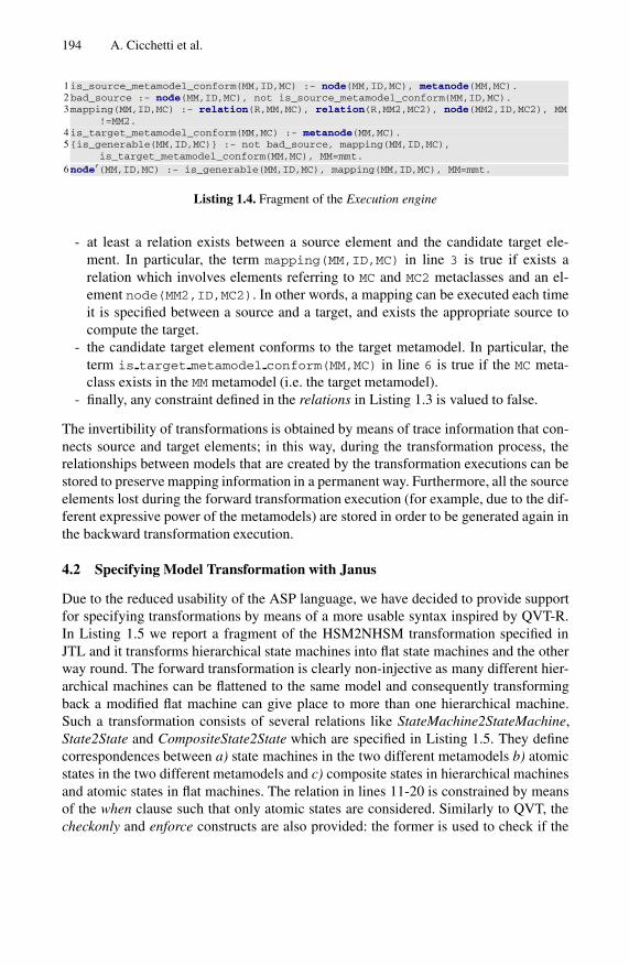
194 A. Cicchetti et al.
1is_source_metamodel_conform(MM,ID,MC) :- node(MM,ID,MC), metanode(MM,MC).2bad_source :- node(MM,ID,MC), not is_source_metamodel_conform(MM,ID,MC).3mapping(MM,ID,MC) :- relation(R,MM,MC), relation(R,MM2,MC2), node(MM2,ID,MC2), MM
!=MM2.4is_target_metamodel_conform(MM,MC) :- metanode(MM,MC).5{is_generable(MM,ID,MC)} :- not bad_source, mapping(MM,ID,MC),
is_target_metamodel_conform(MM,MC), MM=mmt.6node′(MM,ID,MC) :- is_generable(MM,ID,MC), mapping(MM,ID,MC), MM=mmt.
Listing 1.4. Fragment of the Execution engine
- at least a relation exists between a source element and the candidate target ele-ment. In particular, the term mapping(MM,ID,MC) in line 3 is true if exists arelation which involves elements referring to MC and MC2 metaclasses and an el-ement node(MM2,ID,MC2). In other words, a mapping can be executed each timeit is specified between a source and a target, and exists the appropriate source tocompute the target.
- the candidate target element conforms to the target metamodel. In particular, theterm is target metamodel conform(MM,MC) in line 6 is true if the MC meta-class exists in the MM metamodel (i.e. the target metamodel).
- finally, any constraint defined in the relations in Listing 1.3 is valued to false.
The invertibility of transformations is obtained by means of trace information that con-nects source and target elements; in this way, during the transformation process, therelationships between models that are created by the transformation executions can bestored to preserve mapping information in a permanent way. Furthermore, all the sourceelements lost during the forward transformation execution (for example, due to the dif-ferent expressive power of the metamodels) are stored in order to be generated again inthe backward transformation execution.
4.2 Specifying Model Transformation with Janus
Due to the reduced usability of the ASP language, we have decided to provide supportfor specifying transformations by means of a more usable syntax inspired by QVT-R.In Listing 1.5 we report a fragment of the HSM2NHSM transformation specified inJTL and it transforms hierarchical state machines into flat state machines and the otherway round. The forward transformation is clearly non-injective as many different hier-archical machines can be flattened to the same model and consequently transformingback a modified flat machine can give place to more than one hierarchical machine.Such a transformation consists of several relations like StateMachine2StateMachine,State2State and CompositeState2State which are specified in Listing 1.5. They definecorrespondences between a) state machines in the two different metamodels b) atomicstates in the two different metamodels and c) composite states in hierarchical machinesand atomic states in flat machines. The relation in lines 11-20 is constrained by meansof the when clause such that only atomic states are considered. Similarly to QVT, thecheckonly and enforce constructs are also provided: the former is used to check if the
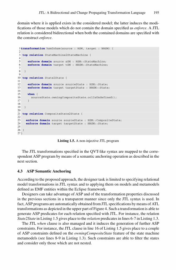
JTL: A Bidirectional and Change Propagating Transformation Language 195
domain where it is applied exists in the considered model; the latter induces the modi-fications of those models which do not contain the domain specified as enforce. A JTLrelation is considered bidirectional when both the contained domains are specified withthe construct enforce.
1transformation hsm2nhsm(source : HSM, target : NHSM) {23 top relation StateMachine2StateMachine {45 enforce domain source sSM : HSM::StateMachine;6 enforce domain target tSM : NHSM::StateMachine;78 }9
10 top relation State2State {1112 enforce domain source sourceState : HSM::State;13 enforce domain target targetState : NHSM::State;1415 when {16 sourceState.owningCompositeState.oclIsUndefined();17 }1819 }2021 top relation CompositeState2State {2223 enforce domain source sourceState : HSM::CompositeState;24 enforce domain target targetState : NHSM::State;2526 }27}
Listing 1.5. A non-injective JTL program
The JTL transformations specified in the QVT-like syntax are mapped to the corre-spondent ASP program by means of a semantic anchoring operation as described in thenext section.
4.3 ASP Semantic Anchoring
According to the proposed approach, the designer task is limited to specifying relationalmodel transformations in JTL syntax and to applying them on models and metamodelsdefined as EMF entities within the Eclipse framework.
Designers can take advantage of ASP and of the transformation properties discussedin the previous sections in a transparent manner since only the JTL syntax is used. Infact, ASP programs are automatically obtained from JTL specifications by means of ATLtransformations as depicted in the upper part of Figure 4. Such a transformation is able togenerate ASP predicates for each relation specified with JTL. For instance, the relationState2State in Listing 1.5 gives place to the relation predicates in lines 6-7 in Listing 1.3.
The JTL when clause is also managed and it induces the generation of further ASPconstraints. For instance, the JTL clause in line 16 of Listing 1.5 gives place to a coupleof ASP constraints defined on the owningCompositeState feature of the state machinemetamodels (see lines 8-9 in Listing 1.3). Such constraints are able to filter the statesand consider only those which are not nested.

196 A. Cicchetti et al.
To support the backward application of the specified transformation, for each JTLrelation additional ASP constraints are generated in order to support the management oftrace links. For instance, the State2State relation in Listing 1.5 induces the generationof the constraints in lines 10-11 of Listing 1.3 to deal with the non-bijectivity of thetransformation. In particular, when the transformation is backward applied on a Stateelement of the target model, trace links are considered to check if such a state hasbeen previously generated from a source CompositeState or State element. If such traceinformation is missing all the possible alternatives are generated.
5 JTL in Practice
In this section we show the application of the proposed approach to the Collapse/Ex-pand State Diagrams case study presented in Section 2. The objective is to illustratethe use of JTL in practice by exploiting the developed environment, and in particularto show how the approach is able to propagate changes dealing with non-bijective andnon-total scenarios. The following sections present how after the definition of modelsand metamodels (see Section 5.1), the JTL transformation may be specified and appliedover them (see Section 5.2). Finally, the approach is also applied to manage changesoccurring on the target models which need to be propagated to the source ones (seeSection 5.3).
5.1 Modelling State Machines
According to the scenario described in Section 2, we assume that in the software de-velopment lifecycle, the designer is interested to have a behavioral description of thesystem by means of hierarchical state machine, whereas a test expert produces non-hierarchical state machine models. The hierarchical and non-hierarchical state machinematamodels (respectively HSM and NHSM) are given by means of their Ecore repre-sentation within the EMF framework. Then a hierarchical state machine model con-forming to the HSM metamodel can be specified as the model reported in the left-handside of Figure 5. Models can be specified with graphical and/or concrete syntaxes de-pending on the tool availability for the considered modeling language. In our case, theadopted syntaxes for specifying models do not affect the overall transformation ap-proach since models are manipulated by considering their abstract syntaxes.
5.2 Specifying and Applying the HSM2NHSM Model Transformation
Starting from the definition of the involved metamodels, the JTL transformation is spec-ified according to the QVT-like syntax described in Section 4.2 (see Listing 1.5). Byreferring to the Figure 4, the JTL program, the source and target metamodels and thesource model have been created and need to be translated in their ASP encoding in or-der to be executed from the transformation engine. The corresponding ASP encodingsare automatically produced by the mechanism illustrated in Section 4. In particular,the ASP encoding of both source model and source and target metamodels is gener-ated according to the Listing 1.2 and 1.1, while the JTL program is translated to thecorresponding ASP program (see Listing 1.3).

JTL: A Bidirectional and Change Propagating Transformation Language 197
Fig. 5. HSM source model and the correspondent NHSM target model
After this phase, the application of the HSM2NHSM transformation on sampleHSMgenerates the corresponding sampleNHSM model as depicted in the right part ofFigure 4. Note that, by re-applying the transformation in the backward direction it ispossible to obtain again the sampleHSM source model. The missing sub-states and thetransitions involving them are restored by means of trace information.
5.3 Propagating Changes
Suppose that in a refinement step the designer needs to manually modify the generatedtarget by the changes described in Section 2 (see Δ changes depicted in Figure 2), thatis:
1. renaming the initial state from Begin Installation to Start Install
shield;2. adding the alternative try again to the state Disk Error to come back to
Install software;3. changing the attributes related to memory requirements (m=500) in the state
Install software and cost (c=200) of the transition from Memory low toInstall software.
The target model including such changes (sampleNHSM’) is shown in the left part of theFigure 6. If the transformation HSM2NHSM is applied on it, we expect changes to bepropagated on the source model. However, due to the different expressive power of the

198 A. Cicchetti et al.
Fig. 6. The modified NHSM target model and the correspondent HSM source models
involved metamodels, target changes may be propagated in a number of different ways,thus making the application of the reverse transformation to propose more solutions.The generated sources, namely sampleHSM’ 1/2/3/4 can be inspected through Figure6: the change (1) has been propagated renaming the state to Start Install shield;the change (2) gives place to a non-bijective mapping and for this reason more than onemodel is generated. As previously said, the new transition can be equally targeted toeach one of the nested states within Install Software as well as to the super stateitself (see the properties sampleHSM’ 1/2/3/4 in Figure 6). For example, as visible inthe property of the transition, sampleHSM’ 1 represents the case in which the transitionis targeted to the composite state Install Software; finally, the change (3) is out ofthe domain of the transformation. In this case, the new values for memory and cost arenot propagated on the generated source models.
Even in this case, if the transformation is applied on one of the derived sampleHSM’models, the appropriate sampleNHSM’ models including all the changes are generated.However, this time the target will preserve information about the chosen sampleHSM’

JTL: A Bidirectional and Change Propagating Transformation Language 199
source model, thus causing future applications of the backward transformation to gen-erate only sampleHSM’.
With regard to the performances of our approach, we performed no formal study onits complexity yet, since that goes beyond the scope of this work; however, our obser-vations showed that the time required to execute each transformation in the illustratedcase study is more than acceptable since it always took less than one second. In thegeneral case, when there are a lot of target alternative models the overall performanceof the approach may degrade.
6 Related Work
Model transformation is intrinsically difficult, and its nature poses a number of obsta-cles in providing adequate support for bidirectionality and change propagation [14]. Asa consequence, despite a number of proposals, in general they impose relevant restric-tions of the characteristics of the involved transformations. For instance, approacheslike [20,21,22,23] require the mappings to be total, while [20,21,5] impose the existenceof some kind of bijection between the involved source and target. Such comparison isdiscussed in [14].
Stevens [7] discusses bidirectional transformations focusing on basic propertieswhich such transformations should satisfy. In particular, (i) correctness ensures a bidi-rectional transformation does something useful according to its consistency relation,(ii) hippocraticness prevents a transformation from does something harmful if nethermodel is modified by users, (iii) finally, undoability is about the ability whether a per-formed transformation can be canceled. The paper considers QVT-R as applied to thespecification of bidirectional transformation and analyze requirements and open issues.Furthermore, it points out some ambiguity about whether the language is supposed tobe able to specify and support non-bijective transformations.
Formal works on bidirectional transformations are based on graph grammars, es-pecially triple graph grammars (TGGs) [15]. These approach interpret the models asgraphs and the transformation is executed by using graph rewriting techniques. It ispossible to specify non-bijective transformations; however, attributes are not modeledas part of the graphs.
In [5] an attempt is proposed to automate model synchronization from model trans-formations. It is based on QVT Relations and supports concurrent modifications onboth source and target models; moreover, it propagates both sides changes in a non de-structive manner. However, some issues come to light: in fact, conflicts may arise whenmerging models obtained by the propagation with the ones updated by the user. More-over, it is not possible to manage manipulations that makes the models to go outside thedomain of the transformation.
The formal definition of a round-trip engineering process taking into account thenon-totality and non-injectivity of model transformations is presented in [14]. The validmodifications on target models are limited to the ones which do not induce backwardmappings out the source metamodel and are not operated outside the transformationdomain. The proposal discussed in this paper is capable also to manage target changesinducing extensions of the source metamodel by approximating the exact source as a

200 A. Cicchetti et al.
set of models; i.e., the set of possible models which are the closest to the ideal one fromwhich to generate the previously modified model.
In [16] the author illustrates a technique to implement a change propagating trans-formation language called PMT. This work supports the preservation of target changesby back propagating them toward the source. On the one hand, conflicts may arise eachtime the generated target should be merged with the existing one; on the other hand, theback propagation poses some problems related to the invertibility of transformations,respectively.
Declarative approaches to model transformations offer several benefits like for exam-ple implicit source model traversal, automatic traceability management, implicit targetobject creation, and implicit rule ordering [9,24]. A number of interesting applications isavailable, varying from incremental techniques [25] to the automation of transformationspecifications by means of the inductive construction of first-order clausal theories fromexamples and background knowledge [26]. One of the closest works to our approachis xMOF [27]. It aims to provide bidirectionality and incremental transformations bymeans of an OCL constraint solving system which enables the specification of modeltransformations. However, transformation developers have no automation support to de-rive constraints from source/target metamodel conformance and transformation rules,which may make their task hard in case of complex mappings [16]. Moreover, it has notbeen clarified how such technique would deal with multiple choices and the require-ments described in Sect. 3.
We already introduced in [28] an ASP based transformation engine enabling the sup-port for partial and non injective mappings. However, the inverse transformation has tobe given by the developer and a valid round-trip process is not guaranteed, as alreadydiscussed throughout the paper. For this purpose, we introduced JTL, a transformationlanguage specifically designed for supporting change propagation with model approxi-mation capabilities.
7 Conclusion and Future Work
Bidirectional model transformations represent at the same time an intrinsically difficultproblem and a crucial mechanism for keeping consistent and synchronized a number ofrelated models. In this paper, we have refined an existing definition of bidirectionalmodel transformations (see [7]) in order to better accommodate non-bijectivity andmodel approximation. In fact, existing languages fail in many respect when dealingwith non-bijectivity as in many cases its semantic implications are only partially ex-plored, as for instance in bidirectional QVT transformations whose standard does noteven clarify whether valid transformations are only bijective transformations. Naturally,non-bijective transformations can possibly map a number of source models to the sametarget model, therefore whenever a target model is manually modified, the changes mustbe back propagated to the related source models.
This paper presented the Janus Transformation Language (JTL), a declarative modeltransformation approach tailored to support bidirectionality and change propagationwhich conforms to the requirements presented in Section 3. JTL is able to map a modelinto a set of semantically related models in both forward and backward directions,

JTL: A Bidirectional and Change Propagating Transformation Language 201
moreover whenever modifications to a target model are making it unreachable fromthe transformation an approximation of the ideal source model is inferred. To the bestof our knowledge these characteristics are unique and we are not aware of any otherlanguage which deals with non-bijectivity and model approximation in a similar way.The expressivity and applicability of the approach has been validated against a relevantbenchmark, i.e., the transformation among hierachical and non-hierarchical state ma-chines as prescribed by [10]. The language has been given abstract and concrete syntaxand its semantics is defined in terms of Answer Set Programming; a tool is availablewhich renders the language interoperable with EMF 7.
As future work we plan to extend the framework with a wizard helping the architectto make decisions among proposed design alternatives. The alternatives are initiallypartitioned, constrained, abstracted, and graphically visualized to the user. Then, whendecisions are made, they are stored and used to drive subsequent decisions. Anotherinteresting future work is to investigate about incremental bidirectional model trans-formations. If a developer changes one model, the effects of these changes should bepropagated to other models without re-executing the entire model transformation fromscratch. In the context of bidirectional transformation it should coexist with the abilityto propagate changes in both the directions but preserves information in the models and,in our case, also allows the approximation of models.
References
1. Schmidt, D.: Guest Editor’s Introduction: Model-Driven Engineering. Computer 39(2), 25–31 (2006)
2. Bezivin, J.: On the Unification Power of Models. Jour. on Software and Systems Modeling(SoSyM) 4(2), 171–188 (2005)
3. Sendall, S., Kozaczynski, W.: Model Transformation: The Heart and Soul of Model-DrivenSoftware Development. IEEE Software 20(5), 42–45 (2003)
4. Stevens, P.: A Landscape of Bidirectional Model Transformations. In: Lammel, R., Visser, J.,Saraiva, J. (eds.) GTTSE 2007. LNCS, vol. 5235, pp. 408–424. Springer, Heidelberg (2008)
5. Xiong, Y., Song, H., Hu, Z., Takeichi, M.: Supporting parallel updates with bidirectionalmodel transformations. In: Paige, R.F. (ed.) ICMT 2009. LNCS, vol. 5563, pp. 213–228.Springer, Heidelberg (2009)
6. Object Management Group (OMG): MOF QVT Final Adopted Specification, OMG AdoptedSpecification ptc/05-11-01 (2005)
7. Stevens, P.: Bidirectional model transformations in qvt: semantic issues and open questions.Software and Systems Modeling 8 (2009)
8. Steven Witkop: MDA users’ requirements for QVT transformations. OMG document 05-02-04 (2005)
9. Czarnecki, K., Helsen, S.: Feature-based Survey of Model Transformation Approaches. IBMSystems J. 45(3) (June 2006)
10. Czarnecki, K., Foster, J.N., Hu, Z., Lammel, R., Schurr, A., Terwilliger, J.F.: BidirectionalTransformations: A Cross-Discipline Perspective. In: Paige, R.F. (ed.) ICMT 2009. LNCS,vol. 5563, pp. 260–283. Springer, Heidelberg (2009)
11. Gelfond, M., Lifschitz, V.: The Stable Model Semantics for Logic Programming. In: Kowal-ski, R.A., Bowen, K. (eds.) Proceedings of the Fifth Int. Conf. on Logic Programming, pp.1070–1080. The MIT Press, Cambridge (1988)
7 http://www.di.univaq.it/romina.eramo/JTL

202 A. Cicchetti et al.
12. Chen, K., Sztipanovits, J., Abdelwalhed, S., Jackson, E.: Semantic Anchoring with ModelTransformations. In: Hartman, A., Kreische, D. (eds.) ECMDA-FA 2005. LNCS, vol. 3748,pp. 115–129. Springer, Heidelberg (2005)
13. Leone, N., Pfeifer, G., Faber, W., Eiter, T., Gottlob, G., Perri, S., Scarcello, F.: The dlv systemfor knowledge representation and reasoning (2004)
14. Hettel, T., Lawley, M., Raymond, K.: Model Synchronisation: Definitions for Round-TripEngineering. In: Vallecillo, A., Gray, J., Pierantonio, A. (eds.) ICMT 2008. LNCS, vol. 5063,pp. 31–45. Springer, Heidelberg (2008)
15. Konigs, A., Schurr, A.: Tool Integration with Triple Graph Grammars - A Survey. ElectronicNotes in Theoretical Computer Science 148, 113–150 (2006)
16. Tratt, L.: A change propagating model transformation language. Journal of Object Technol-ogy 7(3), 107–126 (2008)
17. Jouault, F., Kurtev, I.: Transforming Models with ATL. In: Bruel, J.-M. (ed.) MoDELS 2005.LNCS, vol. 3844, pp. 128–138. Springer, Heidelberg (2006)
18. Budinsky, F., Steinberg, D., Merks, E., Ellersick, R., Grose, T.: Eclipse Modeling Framework.Addison-Wesley, Reading (2003)
19. Bezivin, J., Jouault, F., Rosenthal, P., Valduriez, P.: Modeling in the Large and Modeling inthe Small. In: Aßmann, U., Liu, Y., Rensink, A. (eds.) MDAFA 2003. LNCS, vol. 3599, pp.33–46. Springer, Heidelberg (2005)
20. Van Paesschen, E., Kantarcioglu, M., D’Hondt, M.: SelfSync: A Dynamic Round-Trip Engi-neering Environment. In: Briand, L.C., Williams, C. (eds.) MoDELS 2005. LNCS, vol. 3713,pp. 633–647. Springer, Heidelberg (2005)
21. Giese, H., Wagner, R.: Incremental Model Synchronization with Triple Graph Grammars.In: Wang, J., Whittle, J., Harel, D., Reggio, G. (eds.) MoDELS 2006. LNCS, vol. 4199, pp.543–557. Springer, Heidelberg (2006)
22. Mu, S.-C., Hu, Z., Takeichi, M.: An Injective Language for Reversible Computation. In:Kozen, D., Shankland, C. (eds.) MPC 2004. LNCS, vol. 3125, pp. 289–313. Springer, Hei-delberg (2004)
23. Foster, J., Greenwald, M., Moore, J., Pierce, B., Schmitt, A.: Combinators for bidirectionaltree transformations: A linguistic approach to the view-update problem. ACM Trans. Pro-gram. Lang. Syst. 29(3) (2007)
24. Mens, T., Gorp, P.V.: A Taxonomy of Model Transformation. Electr. Notes Theor. Comput.Sci. 152, 125–142 (2006)
25. Hearnden, D., Lawley, M., Raymond, K.: Incremental Model Transformation for the Evolu-tion of Model-Driven Systems. In: Wang, J., Whittle, J., Harel, D., Reggio, G. (eds.) MoD-ELS 2006. LNCS, vol. 4199, pp. 321–335. Springer, Heidelberg (2006)
26. Balogh, Z., Varro, D.: Model transformation by example using inductive logic programming.Software and Systems Modeling (2009)
27. Compuware and Sun: XMOF queries, views and transformations on models using MOF,OCL and patterns, OMG Document ad/2003-08-07 (2003)
28. Cicchetti, A., Di Ruscio, D., Eramo, R.: Towards Propagation of Changes by Model Ap-proximations. In: 10th IEEE Int. Enterprise Distributed Object Computing Conf. Workshops(EDOCW 2006), vol. 0, p. 24 (2006)

Software Engineering and the Semantic Web:
A Match Made in Heaven or in Hell?
Abraham Bernstein�
Dynamic and Distributed Information Systems GroupDepartment of Informatics, University of ZurichBinzmuhlestrasse 14, 8050 Zurich, Switzerland
http://www.ifi.uzh.ch/ddis/bernstein.html
Abstract. The Semantic Web provides models and abstractions for thedistributed processing of knowledge bases. In Software Engineering en-deavors such capabilities are direly needed, for ease of implementation,maintenance, and software analysis.
Conversely, software engineering has collected decades of experiencein engineering large application frameworks containing both inheritanceand aggregation. This experience could be of great use when, for example,thinking about the development of ontologies.
These examples—and many others—seem to suggest that researchersfrom both fields should have a field day collaborating: On the surfacethis looks like a match made in heaven. But is that the case?
This talk will explore the opportunities for cross-fertilization of thetwo research fields by presenting a set of concrete examples. In additionto the opportunities it will also try to identify cases of fools gold (pyrite),where the differences in method, tradition, or semantics between the tworesearch fields may lead to a wild goose chase.
Keywords: Software Engineering, Semantic Web, Software Analysis,Knowledge Representation, Statistics, Ontologies.
The Semantic Web at Use for Software Engineering Tasksand Its Implications
Semantic Web technologies have successfully been used in recent software en-gineering research. Dietrich [2], for example, proposed an OWL1 ontology tomodel the domain of software design patterns [4] to automatically generatedocumentation about the patterns used in a software system. With the help of� I would like to thank the participants of the Semantic Web Software Engineering
Workshop (SWSE) at the International Semantic Web Conference (ISWC) 2009 fortheir valuable comments on an earlier version of this presentation. Partial supportfor some of the work presented in this talk was provided by Swiss National ScienceFoundation award number 200021-112330.
1 http://www.w3.org/TR/owl2-overview/
B. Malloy, S. Staab, and M. van den Brand (Eds.): SLE 2010, LNCS 6563, pp. 203–205, 2011.c© Springer-Verlag Berlin Heidelberg 2011

204 A. Bernstein
this ontology, the presented pattern scanner inspects the abstract syntax trees(AST) of source code fragments to identify the patterns used in the code.
Highly related is the work of Hyland-Wood et al [6], in which the authors presentan OWL ontology of Software Engineering Concepts (SECs). Using SEC, it is pos-sible to enable language-neutral, relational navigation of software systems to fa-cilitate software understanding and maintenance. The structure of SEC is verysimilar to the language structure of Java and includes information about classesand methods, test cases, metrics, and requirements of software systems. Informa-tion from versioning and bug-tracking systems is, however, not modeled in SEC.
Both, Mantyla et al [7] and Shatnawi and Li [8] carried out an investigationof code smells [3] in object-oriented software source code. While the study ofMantyla additionally presented a taxonomy (i.e., an ontology) of smells andexamined its correlations, both studies provided empirical evidence that somecode smells can be linked with errors in software design.
Happel et al [5] presented the KOntoR approach that aims at storing andquerying metadata about software artifacts in a central repository to foster theirreuse. Furthermore, various ontologies for the description of background knowl-edge about the artifacts such as the programming language and licensing modelsare presented. Also, their work includes a number of SPARQL queries a devel-oper can execute to retrieve particular software fragments which fit a specificapplication development need.
More recently Tappolet et al [9] presented EvoOnt,2 a set of software ontolo-gies and data exchange formats based on OWL. EvoOnt models software design,release history information, and bug-tracking meta-data. Since OWL describesthe semantics of the data, EvoOnt (1) is easily extendible, (2) can be processedwith many existing tools, and (3) allows to derive assertions through its inherentDescription Logic reasoning capabilities. The contribution of their work is thatit introduces a novel software evolution ontology that vastly simplifies typicalsoftware evolution analysis tasks. In detail, its shows the usefulness of EvoOntby repeating selected software evolution and analysis experiments from the 2004-2007 Mining Software Repositories Workshops (MSR). The paper demonstratesthat if the data used for analysis were available in EvoOnt then the analysesin 75% of the papers at MSR could be reduced to one or at most two simplequeries within off-the-shelf SPARQL3 tools. In addition, it presents how the in-herent capabilities of the Semantic Web have the potential of enabling new tasksthat have not yet been addressed by software evolution researchers, e.g., due tothe complexities of the data integration.
This semi-random4 selection examples clearly illustrate the usefulness of Se-mantic Web technologies for Software Enginering.
Conversely, decades of experience in engineering large application frameworkscontaining both inheritance and aggregation provides a sound foundation for theusefulness of Software Engineering techniques to Semantic Web research.
2 http://www.ifi.uzh.ch/ddis/research/evoont/3 http://www.w3.org/TR/rdf-sparql-query/4 All of the examples are focused on Semantic Web enabled software analysis.

Software Engineering and the Semantic Web 205
These insights seem to suggest that researchers from the fields should have afield day collaborating: On the surface this looks like a match made in heaven.But is that the case?
The main purpose of this talk is to identify the opportunities for cross-fertilization between the two research fields by presenting a set of concreteexamples.
To contrast these opportunities it will also try to identify possible barriersand/or impediments to collaboration, where the differences in method, tradition,or semantics between the two research fields may lead to a wild goose chase.
References
1. Demeyer, S., Tichelaar, S., Steyaert, P.: FAMIX 2.0—the FAMOOS inf. exchangemodel. Tech. rep., University of Berne, Switzerland (1999),http://www.iam.unibe.ch/~famoos/FAMIX/Famix20/Html/famix20.html
2. Dietrich, J., Elgar, C.: A formal description of design patterns using OWL. In:Proceedings of the Australian Software Engineering Conference, Brisbane, Australia(2005)
3. Fowler, M.: Refactoring. Addison-Wesley, Reading (1999)4. Gamma, E., Helm, R., Johnson, R.E.: Design Patterns. Elements of Reusable
Object-Oriented Software. Addison-Wesley Longman, Amsterdam (1995)5. Happel, H.-J., Korthaus, A., Seedorf, S., Tomczyk, P.: KOntoR: An Ontology-
enabled Approach to Software Reuse. In: Proceedings of the 18th Internatinal Con-ference on Software Engineering and Knowledge Engineering (SEKE), San Fran-cisco, CA (2006)
6. Hyland-Wood, D., Carrington, D., Kapplan, S.: Toward a Software MaintenanceMethodology using Semantic Web Techniques. In: Proceedings of the 2nd ICSMInternational Workshop on Software Evolvability (SE), pp. 23–30 (2006)
7. Mantyla, M., Vanhanen, J., Lassenius, C.: A Taxonomy and an Initial EmpiricalStudy of Bad Smells in Code. In: Proceedings of the International Conference onSoftware Maintenance (ICSM), pp. 381–384 (2003)
8. Shatnawi, R., Li, W.: A Investigation of Bad Smells in Object-Oriented Design Code.In: Proceedings of the 3rd International Conference on Information Technology: NewGenerations, pp. 161–165 (2006)
9. Tappolet, J., Kiefer, C., Bernstein, A.: Semantic web enabled software analysis.Journal of Web Semantics: Science, Services and Agents on the World Wide Web 8(July 2010)

A Unified Format for Language Documents
Vadim Zaytsev and Ralf Lammel
Software Languages TeamUniversitat Koblenz-Landau
Universitatsstraße 156072 Koblenz
Germany
Abstract. We have analyzed a substantial number of language doc-umentation artifacts, including language standards, language specifica-tions, language reference manuals, as well as internal documents ofstandardization bodies. We have reverse-engineered their intended in-ternal structure, and compared the results. The Language DocumentFormat (LDF), was developed to specifically support the documentationdomain. We have also integrated LDF into an engineering discipline forlanguage documents including tool support, for example, for renderinglanguage documents, extracting grammars and samples, and migratingexisting documents into LDF. The definition of LDF, tool support forLDF, and LDF applications are freely available through SourceForge.
Keywords: language documentation, language document engineering,grammar engineering, software language engineering.
1 Introduction
Language documents form an important basis for software language engineeringactivities because they are primary references for the development of grammar-based tools. These documents are often viewed as static, read-only artifacts.We contend that this view is outdated. Language documents contain formalizedelements of knowledge such as grammars and code examples. These elementsshould be checked and made available for the development of grammarware.Also, language documents may contain other formal statements, e.g., assertionsabout backward compatibility or the applicability of parsing technology. Again,such assertions should be validated in an automated fashion. Furthermore, themaintenance of language documents should be supported by designated tools forthe benefit of improved consistency and traceability. In an earlier publication, anote for ISO [KZ05], we have explained why a language standardization bodyneeds grammar engineering (or document engineering).
This paper presents a data model (say, metamodel or grammar) for de-veloping language documents. Upon analyzing and reverse-engineering a widerange of language documents, which included international ISO-approved stan-dards and vendor-specific 4GL manuals, we have designed a general format forlanguage documents, the Language Document Format (LDF), which supports
B. Malloy, S. Staab, and M. van den Brand (Eds.): SLE 2010, LNCS 6563, pp. 206–225, 2011.c© Springer-Verlag Berlin Heidelberg 2011

A Unified Format for Language Documents 207
the documentation of languages in a domain-specific manner. We have integratedLDF with a formalism for syntax definition that we designed and successfullyutilized in previous work [LZ09, LZ10, Zay10b].
We have integratedLDF also with existing tools and methods for grammar engi-neering from our previouswork; see the grammar life cycle at the top of Figure 1 foran illustration. Furthermore, we have added LDF-specific tools, and begun work-ing towards a discipline of language document engineering. There is support forcreating, rendering, testing, and transforming language documents; see the docu-ment life cycle at the bottom of Figure 1 for an illustration. Given the new formatLDF, it is particularly important that there are document extractors so that onecan construct consistent LDF documents from existing language documents.
In this paper, we will be mainly interested in LDF as the format for languagedocuments, and the survey that supports the synthesis of the LDF format. Thebroader discussion of language document engineering is only sketched here. Forinstance, most aspects of rich tool support are deferred to substantial futurework efforts.
LDF can be seen as an application of literate programming [Knu84] ideologyto the domain of language documentation: we aim to have one artifact that isboth readable and executable. By “readable” we mean its readability, under-standability and information retrievability qualities. By “executable” we assumea proper environment such as a compiler compiler (for parser definitions) or aweb browser (for hyperlinked grammars). LDF provides us with a data modelnarrowly tailored to the domain; it allows us to focus on one baseline artifactwhich is meant for both understanding and formal specification. Other artifactssuch as grammars, test sets, web pages, language manuals and change documentsare considered secondary in that they are to be generated or programmed. Thefull realization of this approach relies on a transformation language for languagedocuments that we will briefly discuss.Summary of contributions
– We have analyzed a substantial number of language documentation artifacts,including language standards, specifications and manuals of languages suchas BNF dialects, C, C++, C#, Cobol dialects, Fortran, 4GLs, Haskell, Jovial,Python, SDF, XML, and other data modeling languages. Company-specificinternal documents and software engineering books that document a softwarelanguage (e.g., [GHJV95] with the well-known design patterns) were alsoresearched. The objective of the analysis was to identify domain conceptsand structuring principles of language documentation.
– We have designed the Language Document Format (LDF) to specifically sup-port the documentation domain, and to make available language documentsto language document engineering.
Validation
We have applied LDF to a number of language documentation problems, buta detailed discussion of such problems is not feasible in this paper for space

208 V. Zaytsev and R. Lammel
Grammar focus
Document focus
Fig. 1. Megamodels related to language document engineering. At the top,we see the life cycle of grammar extraction, recovery, and deployment. Grammars areextracted from existing software artifacts on the left, and represented in the unifiedformat BGF. Grammars may then be subject to transformation using the XBGF trans-formation language. Parsers, browsable grammars, and other “executable” artifacts aredelivered on the right. Such grammar engineering feeds into language document engi-neering. At the bottom, we see the life cycle of language document extraction, language(document) evolution, generation of end-user documents, extraction of grammars andtest suites. Non-LDF documents can be converted to LDF through the extractionshown on the left. Document transformation may be needed for very different reasons,e.g., structure recovery or language evolution; see the reference to XLDF, which is thetransformation language for LDF.

A Unified Format for Language Documents 209
reasons. For instance, we have applied language document engineering system-atically to the documentation of XBGF—the transformation language for BGFgrammars which is used extensively in our work on grammar convergence; theoutcome of this case study is available online [Zay09]. In the current paper, webriefly consider mapping W3C XML to LDF, specifically W3C’s XPath stan-dard; this case study is available online, too [W3C]. In the former case, we relyon a document extractor that processes XSD schemata in a specific manner. Inthe latter case, the extractor maps W3C’s XML Spec Schema to LDF.
More generally, the SourceForge project “Software Processing Language Suite”(SLPS)1 hosts the abovementioned two case studies, the LDF definition, toolsupport for LDF, other LDF applications, and all other grammars and toolsmentioned in this paper and our referenced, previous work. For instance, werefer to the SLPS Zoo2, which contains a collection of grammars that we ex-tracted from diverse language documents. The next step would be to properlyLDF-enable all these documents.
Road-map
The rest of the paper is organized as follows. §2 discusses the state of the art inlanguage documentation as far as it affects our focus on a format for languagedocuments and its role in language document engineering. §3 identifies the con-cepts of language documentation as they are to be supported by a unified formatfor language documents, and as they can be inferred, to some extent, from exist-ing language documents. §4 describes the Language Document Format (LDF) interms of the definitional grammar for LDF. It also provides a small scenario forlanguage document transformation. §5 discusses related work (beyond the stateof the art section). §6 concludes the paper.
2 State of the Art in Language Documentation
As a means of motivation for our research on a unified format for languagedocuments, let us study the state of the art in this area. The bottom line of thisdiscussion is that real-world language documents are engineered at a relativelylow level of support for the language documentation domain.
2.1 Background on Language Standardization
In practice, all mainstream languages are somehow standardized; the standard ofa mainstream language would need to be considered the primary language doc-ument. For instance, the typical standard for a programming language entailsgrammar knowledge and substantial textual parts for the benefit of understand-ing the language.
Let us provide some background on language standardization. In particu-lar, we list standardization bodies, and we discuss some of the characteristics of
1 SLPS project, slps.sf.net2 SLPS Zoo, slps.sf.net/zoo

210 V. Zaytsev and R. Lammel
language standards. Standardization bodies that produce, maintain and dis-tribute language standards, are, among others:
– American National Standards Institute (ANSI, since 1918), ansi.org– European Computer Manufacturers Association (ECMA, since 1961),
ecma-international.org– Institute of Electrical and Electronics Engineers Standards Association
(IEEE-SA, since 1884), standards.ieee.org– International Electrotechnical Commission (IEC, since 1906), iec.ch– International Organization for Standardization (ISO, since 1947),
open-std.org– International Telecommunication Union (ITU, since 1865), itu.int– Internet Engineering Task Force (IETF, since 1986), ietf.org– Object Management Group (OMG, since 1989), omg.org– Organization for the Advancement of Structured Information Standards
(OASIS, since 1993), oasis-open.org– Website Standards Association (WSA, since 2006), websitestandards.org– World Wide Web Consortium (W3C, since 1994), w3.org
A language specification (programming language standard) is a complex doc-ument that may consist of hundreds of pages: the latest COBOL standard,ISO/IEC 1989:2002 [ISO02], has more than 800 pages; the latest C [ISO05]and C# [ECM06] standards contain over 500 pages each, C++ draft is alreadywell over 1100 pages [ISO07]. It has not always been like that. For example,the Algol 60 standard [BBG+63] is not much longer than 30 pages, and yet, itclaimed to contain a complete definition of the language. However, as program-ming languages evolve, their specifications grow in size. Also, the complicatedstructure of modern language documents reflects the complicated structure ofmodern programming languages and the associated ecosystems.
2.2 The Language Documentation Challenge
Writing and maintaining a quality language document and keeping it consis-tent is as complex as writing and maintaining a large software system—theseprocesses have a lot in common.
Defining a programming language in a standardized specification is often con-sidered as a process that is executed just once. The dynamic and evolving natureof programming languages is frequently underestimated and overlooked [Fav05].Not only software itself, but programming languages that are used to make it,evolve over time. This process usually comes naturally in the sense that the firstversion of a language does not have all the features desired by its creator. Also,new requirements may be discovered for a language, and hence, the languageneeds to be extended or revised. However, it is desirable for that process to beguided and controlled for the sake of the quality of resulting specifications.
There are tools like parsers and compilers whose development is based ona language specification. Inconsistencies in the language documents may leadto non-conformant language tools; such inconsistencies certainly challenge theeffective use of the language documents. Languages need to evolve, and hence, it

A Unified Format for Language Documents 211
should be easy enough to evolve language documents. However, with the currentpractice of language standardization, evolution of language documents may betoo ad-hoc, error-prone and labor-intensive; see, for example, our previous studyon the language documentation for the Java Language Specification [LZ10].
Overall, it is difficult to support language evolution for programming lan-guages or software languages that are widely used. We contend that a systematicapproach to language documents is an important contribution to a reliable andscalable approach to language evolution in practice.
2.3 Language Documentation Approaches
In practice, language documents are created and maintained with various tech-nologies, e.g., LATEX [ISO08], HTML [BBC+07], Framemaker [ISO02], home-grown DSLs based on the language being defined in the document [Bru05], XMLSchema [Zay09], DITA, DocBook. The creation and maintenance of languagedocument is also regulated by practices of design committees and standardiza-tion bodies or simply language document editors. The practices are often con-strained by the technologies (or vice versa). We make an attempt to organizetechnologies and practices. To this end, we identify different language documen-tation approaches.
The text- and presentation-oriented approach considers a languagespecification as a text document subject to text editing. The editor manuallyadds text to the document, manages section structure, moves around paragraphsand other units of text, performs layout and formatting operations. Typically,the text is meant to be immediately ready for presentation—perhaps even basedon WYSIWYG.
The course of action for an editor of a language document is often describedin a separate “change document” that is created before the actual change takesplace or directly after it. The change document comprises a list of intended modi-fications. Once the editing process reaches a certain milestone, a new “revision” isdelivered and stored in the repository. Once all the modifications approved by thelanguage design committee are brought upon the main document, a new “version”is delivered and officially distributed within the terms of its license. This approachtends to utilize programs like Adobe Framemaker (ISO/IEC JTC1/SC22/WG43),Microsoft Word (Microsoft version of C# [Mic03]), etc. It is also possible to useHTML (early W3C [Rag97]) in such a way that the main document is edited man-ually and the changes are discussed and/or documented elsewhere.
This approach involves significant low-level text editing. The links betweenthe change documents and the main document revisions often remain unverified.(Versioning and change tracking facilities can be too constraining.) Any struc-tured content that is a part of a language document must be formatted in a waydictated by the medium: e.g., the formulæ can only use the symbols availablein the font. It is also common to have several differently organized layers in theinfrastructure: e.g., the main document is edited by one person following the3 ISO/IEC JTC1/SC22/WG4 — COBOL Standardization Working Group,http://www.cobolstandard.info/wg4/wg4.html

212 V. Zaytsev and R. Lammel
instructions in the change document, but the change documents circulate in theform of co-authored Word documents.
The structure-oriented approach operates on documentation domain con-cepts such as “sections” or “divisions”. The approach may leverage existingediting software to support maintenance activities at the central repository ofstructured data. The approach also leverages backend tools that produce PDF,LATEX, and other types of deliverables. An example of such a documentationsupport system is DocBook [WM99]. It is a mature, well-document, activelyused technology. For instance, Microsoft uses DocBook to generate help files forWindows applications.
The separation between the content and its presentation can be sufficient inDocBook and similar systems. However, their orientation on books does notanticipate documents that have several intertwined hierarchies. In a languagedocument, for example, a grammar production that is a part of the correspond-ing section, is also a part of the complete grammar in the appendix, and shouldappear there automatically (as opposed to being manually cloned). In principle,one could leverage transformations (such as XSLT for DocBook) for the repre-sentation of the evolution of a (language) document. We are not aware of relatedwork of this kind.
The topic-oriented approach operates in terms of “topics” that should becovered in order for the documentation to be complete. The DocBook counterpartin this group of approaches is Darwin Information Typing Architecture (DITA)[OAS07] which was designed specifically for authoring, producing and deliveringtechnical information. IBM uses DITA for their hardware documentation. PDF,HTML, Windows help files and other output formats are possible. DITA is a rela-tively modern technology (2004 versus 1991 for DocBook), its support is growing,but is not as mature as for DocBook. A more lightweight approach is wiki tech-nology that allows for topics to be left uncovered, showing explicitly which partsof the documentation are intended to be written in the future.
Language documentation is not naturally organized in topics and tasks, andthus is not anticipated by DITA. In principle, it is possible to use DITA to repre-sent our proposed model (LDF). In order to do that, necessary element types—like grammar productions, code examples, notes concerning version differences,optional feature descriptions, possible implementation remarks, language engi-neering explanations—would need to be defined. Designated backends will alsobe required. There is no apparent benefit of using DITA, when compared to theXML/XSD-based approach that we chose for LDF’s description.
The XML Spec Schema, available from http://www.w3.org/2002/xmlspec,combines elements of structure and topic orientation in a manner that bringsus closer to the domain of language documentation. The XML Spec Schemais a DTD that is used for some W3C recommendations. It is based on theliterate programming tag set SWEB and the text encoding tag set TEI Lite.The Spec Schema covers some elements of the language documentation domainsuch as tagging facilities for grammar fragments; it does not capture LDF’s richclassification of sections in language documents.

A Unified Format for Language Documents 213
3 Concepts of Language Documentation
As a preparatory step towards introducing LDF, we identify the concepts of thelanguage documentation domain. We set up a control group to this end, and wealso illustrate several concepts specifically for one member of the control group:the XPath W3C Recommendation.
3.1 Control Group for the Domain Model
As we have indicated in the introduction, we have consulted a large set of lan-guage documents to eventually synthesize a unified format. For reasons of scala-bility, we have selected a smaller set of documents which we use here to presentthe results of our reverse-engineering efforts and to prepare the synthesis of aunified format for language documents. The control group of documents has beenchosen for its diversity. Table 1 shows some basic metadata about the languagedocuments for the control group. Here is a short description of the control group:
Table 1. Some basic metadata of the standards chosen for the survey
IAL Jovial Patterns Smalltalk Informix C# MOF XPathProperty [Bac60] [MIL84] [GHJV95] [Sha97] [IBM03] [ECM06] [MOF06] [BBC+07]Body ACM DoD — ANSI IBM ECMA, ISO OMG W3CCompany IBM — Pearson — IBM Microsoft — —Year 1960 1984 1995 1997 2003 2006 2006 2007Pages 21 158 395 304 1344 548 88 111Notation BNF BNF UML BNF RT BNF UML EBNF
– IAL stands for International Algebraic Language that later became knownas Algol-58 [Bac60]. It is historically the first programming language docu-ment, and as such, it is the first time that the notation for specifying gram-mar productions was explicitly defined. The majority of all other standardsproduced over the following decades re-used this notation and extended it.
– JOVIAL, or J73 [MIL84] is a Military Standard of 1984, which “has beenreviewed and determined to be valid” in 1994. It is approved for use by theDepartment of the Air Force and is available for use by all other Depart-ments and Agencies of the Department of Defense of USA. The version thatwas examined in this survey is a result of a second upgrade of the originallanguage. It is less than 200 pages and very strictly composed: basically ev-ery section has a syntax, semantics and constraints subsections, with rarenotes or examples. A traditional BNF is used for syntax, plain English forsemantics.
– Design Patterns: Elements of Reusable Object-Oriented Software [GHJV95]is a well-known book by Erich Gamma et al., which defines 23 well-knowndesign patterns. Since design patterns can be considered a special language,their definition can be considered a language document—and Table 2 onlyproves that, letting the 400 pages long book’s structure fit in the generaldata model perfectly.

214 V. Zaytsev and R. Lammel
– ANSI Smalltalk [Sha97] is an NCITS J20 draft of 1997, 300+ pages long,it describes both the language (ANSI Smalltalk is derived from Smalltalk-80)and the Standard Class Library.
– Informix [IBM03] is an IBM manual for a proprietary fourth generationlanguage. It exemplifies industrial standards, which are extensively strictlystructured, contain minimum extra sections and have impressive volume.Informix specification utilizes “railroad track” syntax diagrams, which canbe mapped more or less directly to EBNF.
– C# specification [Mic03, ECM06] is both an ISO and an ECMA standard,yet it was developed entirely within Microsoft and only approved by stan-dardization bodies. The ECMA version used for this survey is 550 pages longand very loosely structured, explaining a lot of issues in running text andusing liberal sub-sectioning.
– MOF Core Specification [MOF06] is a 90-pages long document describ-ing Meta Object Facility. It uses UML and presents the information in asignificantly different way, being oriented on diagrams, properties, opera-tions and constraints. However, structuring overall turns out to be similarto conventional (E)BNF-based standards.
– The structure of XPath W3C Recommendation [BBC+07] is rathervolatile, following the tradition of all other W3C recommendations. Eachsection contains one or several EBNF formulæ, the definition for a domainconcept modeled by it and a body of text organized arbitrarily in lists andsubsections.
3.2 Identification of Concepts
The core domain concepts of LDF are these: synopsis, description (an extendedtextual definition), syntax (associated grammar productions), constraints (re-stricting the use of the construct), references (to other language constructs),relationship (with other language constructs), semantics, rationale, exam-ple, update (from the previous language version), default (for absent parts).Four additional concepts can occur multiple times: value (associated named pieceof metadata), list (itemized data), section (volatile textual content), subtopic(structured section).
Table 2 compares the documents from the control group in terms of the do-main concepts. The cells in the table are filled with names of the sections, sub-sections or otherwise identifiable paragraphs in the corresponding documents,unless noted otherwise. The coverage graph shows fully covered parts of LDF inblack (represented by section names in table cells), partially covered in gray (“∼”in a table cell means that the information is given but lacks any specific markup)and not covered in white (“—” in a cell means that this kind of information isabsent from the language document). Gray concepts are interesting in so far thatwe face instances of implicit structure which can only be recovered with humanintervention or advanced information retrieval techniques in the extraction tool.
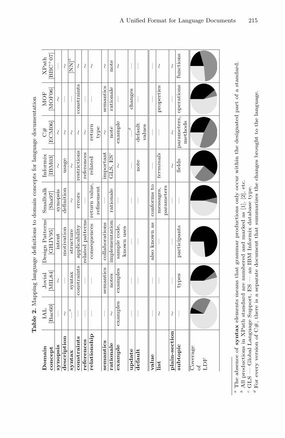
A Unified Format for Language Documents 215
Table
2.M
appi
ngla
ngua
gede
finit
ions
todo
mai
nco
ncep
tsfo
rla
ngua
gedo
cum
enta
tion
Domain
IAL
Jovial
DesignPatterns
Smalltalk
Inform
ixC#
MOF
XPath
concept
[Bac60]
[MIL
84]
[GHJV95]
[Sha97]
[IBM03]
[ECM06]
[MOF06]
[BBC
+07]
synopsis
—∼
intent
synopsis
∼∼
∼—
description
∼—
motivation
definition
usage
∼—
∼syntax
—a
syntax
structure
∼∼
∼—
[NN]b
constraints
—constraints
applicability
errors
restrictions
∼constraints
∼references
——
relatedpatterns
—references
∼—
∼relationship
——
consequences
return
value,
related
return
—∼
refinement
type
semantics
—semantics
collaborations
—im
portant
∼semantics
∼rationale
∼notes
implementation
rationale
GLS,ESc
note
rationale
note
example
examples
examples
sample
code,
—∼
example
—∼
knownuses
update
——
——
——
dchanges
—
default
——
——
note
default
——
values
value
——
alsoknownas
conform
sto
——
——
list
∼—
—messages,
term
inals
—properties
∼parameters
plain-section
∼—
——
∼∼
—∼
subtopic
—types
participants
—fields
parameters,operations
functions
methods
Coverage
of
LDF
aTheabsenceofsyntaxelements
meansthatgrammarproductionsonly
occurwithin
thedesignatedpart
ofastandard.
bAllproductionsin
XPath
standard
are
numberedandmarkedas[1],[2],etc.
cGLS—
GlobalLanguageSupport,ES—
anIB
MInform
ixdatabase
type.
dForevery
versionofC#,there
isaseparate
documentthatsummarizesthechangesbroughtto
thelanguage.

216 V. Zaytsev and R. Lammel
3.3 Example: The XPath Language Document
The discovery of a language document’s structure and underlying domain con-cepts is a genuine process which we would like to sketch here for one example.We have chosen XPath 1.0 for this purpose—mainly because of its modest size.
The XML Path Language 1.0 specification [CD99] is one of the small stan-dards, it contains only 32 pages in the printed version. We perform a cursoryexamination of it, trying to locate the domain concepts identified in the previoussection:
Synopsis — is not automatically retrievable. We contend that, in some sec-tions, the first sentence seems to serve as a synopsis (e.g., “Every axis has aprincipal node type.”).
Description — if no specific structure can be recovered, we will treat all sectioncontent as a description.
Syntax — when we use the XML version of the specification as a source, allgrammar productions are easily identifiable by the <scrap> tag. A specificparser had to be developed in XSLT to deal with the mix of plain text (e.g.,for EBNF metasymbols) and XML tags (e.g., for nonterminal symbols).
Constraints — some of the Notes are mentioning constraints (e.g., “The num-ber function should not be used...”), but they are not automatically distin-guishable from other Notes.
References — since all nonterminal names are always annotated with hyper-links to the corresponding sections, no explicit references are required.
Relationship — there are mentions of relationships, some of which are eveninter-documentary (e.g., the mod operator is being compared to the % op-erator in ECMAScript and the IEEE 754 remainder operation, but it isimpossible to derive them naturally during recovery.
Semantics — is defined in plain English in running text.Rationale — almost all Notes can be classified as providing rationales. We map
them all to rationales at the extraction step. Exceptions would need to behandled by programmed transformations.
Example — as typical for a W3C document, examples sections are inlined, butpreceded by the sentences like “for example,” or “here are some examples”.
Update — XPath 1.0 is the first specification of its kind, which means that itcontains no updates.
Default, Value — not found in this standard.List — found inside the <ulist> and <slist> tags in the XML version of the
document.Section — Data Model section contains simple subsections.Subtopic — every function description (the <proto> tag) can be treated as a
subtopic. They are never long, but still can contain structured informationsuch as lists and examples.
The global structure of the XPath specification is mapped to LDF in a straight-forward fashion: for example, specific sections within the <header> such as Ab-stract and Status form a front matter part; <body> subsections populate the

A Unified Format for Language Documents 217
core part; <back> subsections become the back matter part. The mapping ismainly terminological: i.e., Status becomes “scope”, “Introduction” becomes“foreword”, etc. The extracted LDF for XPath 1.0 is available as [W3C].
4 A Unified Format for Language Documents
We will now describe the Language Document Format (LDF)—a unified formatfor language documents (say, language documentation). Given the motivationof LDF in previous sections, we will focus here on the actual language descrip-tion for LDF. LDF’s description is available online through the SLPS Source-Forge project as shared/xsd/ldf.xsd. (LDF’s primary description leveragesXML Schema.) This section presents and discusses a full grammar for (current)LDF. The grammar notation we use here is a pretty-printed EBNF dialect calledBGF [LZ10, Zay10b, Zay10a], for BNF-like Grammar Format, which should beintuitively comprehensible. For brevity’s sake, some more routine (obvious) for-mat elements are skipped in the discussion.
4.1 Language Document Partitioning
Consider the following productions concerning the document top sort and toplevel sections. For example, a document always contains one document meta-data, and one or more parts. Each part also contains a portion of metadata,and consists of sections of various types.
document:
document-metadata part+
document-metadata:
body? number::string? author::person� topic::string status
version-or-edition previous::named-link� date::time-stampbody:
ansi::ε | ecma::ε | ieee::ε | iso::ε | iso/iet::ε | itu::ε | iec::ε| ietf::ε | oasis::ε | omg::ε | wsa::ε | w3c::ε
person:
name::string affiliation::string? email::string?status:
unknown::ε | draft::ε | candidate::ε | proposed::ε | approved::ε| revised::ε | obsolete::ε | withdrawn::ε | collection::ε| trial::ε | errata::ε | report::ε
version-or-edition:
version::string | edition::stringnamed-link:
title::string version-or-edition? uri::any-uri?part:
part-metadata section+
part-metadata:
id::id? part-role title::string? author::person�
part-role:
front-matter::ε | core-part::ε | back-matter::ε | annex::ε

218 V. Zaytsev and R. Lammel
Most of the structural facets and elements should be self-explanatory. Let ushighlight here the mandatory division of each language document into parts. Inthis manner, we encourage more structure than a simple list of top-level chapters.Existing documents vary greatly in the order of sections and their presentation.For instance, “conformance” and “references” sections are usually found in thefront matter between the title page and the core chapters, but in the XPath1.0 standard [CD99], conformance is the last core chapter, and references forman appendix. LDF’s emphasis on parts encourages some grouping among themany sections.
4.2 Top Sections
On the top level, several types of sections can be found. First, there are sim-ple sections that have no or minimal subdivisioning and dedicate themselves toone specific (side) issue—they are commonly found in the front or back matter.They can also describe lexical details, in such case we identify several commonlyencountered section roles. Finally, there can be container sections—each of themexplains one language construct and presents information in a specifically struc-tured way.
section:
section-metadata section-structure
section-metadata:
id::id? section-role type? title::string? author::person�
section-role:
abstract::ε | conformance::ε | compatibility::ε | design-goals::ε| outline::ε | foreword::ε | references::ε | scope::ε | index::ε| notation::ε | what-is-new::ε | full-grammar::ε | tables-list::ε| authors-list::ε | contents::ε | overview::ε | lexical-issue::ε| line-continuations::ε | literals::ε | preprocessor::ε| tokens::ε | whitespace::ε | glossary::ε | container::ε
type:
normative::ε | informative::εsection-structure:
content::(content-content+)
placeholder::εsubsection+
As shown above, the metadata of a top section contains a possible id that isused to refer to it from elsewhere; the role of the section; possibly its type; apossible specific title (if absent, assumed to be determined by the role); and apossible list of authors (if absent, assumed to be equal to the list of the documentauthors). If the id is missing, one can still use an XPath expression over thedocument structure to access the section at hand (by its position, title or otherdistinctive features). However, explicit ids are potentially preferred because oftheir greater robustness with regard to document evolution.
A type relates to the way the content of the section should be treated: forexample, an informative code sample is a way to tell the reader how a piece

A Unified Format for Language Documents 219
of code would look like, but a normative one can serve as an official test case.Placeholders can be used if the content can be generated automatically: forexample, a references section can be written manually in a verbose way with lotsof useful annotations, but it can also be just a list of all references occurring inthe rest of the specification.
The list of section roles was synthesized from the reverse-engineered lan-guage documents. The roles should be intuitively understandable, but the con-crete wording may vary: a particular foreword can be called “introduction”the same way that an obsolete standard can be called “rescinded”. Further-more, roles are not exclusively one per document: for example, there can be one“glossary” for the list of definitions and one for the list of abbreviations.
4.3 Inner Sections
As discussed above, the inner sections of the simple top sections are ratherunsophisticated, but a container section explaining one syntactic category con-sistently shows the same set of possible subsections across many manuals andstandards that we analyzed. The exact set of container sections depends on theset of categories and is therefore very language dependent.
subsection:
subsection-metadata section-structure
subsection-metadata:
id::id? subsection-role type? title::string? author::person�
subsection-role:
synopsis::ε | description::ε | syntax::ε | constraints::ε| references::ε | relationship::ε | semantics::ε | rationale::ε| example::ε | update::ε | default::ε | value::ε | list::ε| plain-section::ε | subtopic::ε
Subsections have roles that map directly to the domain concepts already beenseen in Table 2.
4.4 Detailed Content
Language documents, especially modern standards, have structured content evenat the textual level of a section: hyperlinks, other references, tables, figures, for-mulæ, lists, inline code fragments are among the most commonly used formattingelements.
content-content:
empty::ε | code::string | para::mixed | list | figure | table
| formula | sample::(string source::string) | production
list:
item::mixed+
figure:
figure-metadata figure-source+
figure-metadata:
id::id? short-caption::string? caption::string author::person�

220 V. Zaytsev and R. Lammel
figure-source:
type::figure-type location::any-urifigure-type:
PDF::ε | PostScript::ε | SVG::ε | PNG::ε | GIF::ε | JPEG::εtable:
header::table-row� row::table-row+
table-row:
table-cell::content-content
For formulæ we reuse MathML[ABC+01], which definition is omitted here. Forproductions we reuse BGF [LZ10, Zay10b, Zay10a]—the same notation we usein this paper.
We allow multiple figure sources so that the rendering tools for LDF can pickthe source that is most convenient for the desired output format. For instance,a bitmap (PNG, GIF, JPEG) picture can be easily inserted into a web page,but a PDF file cannot be used in this manner. However, PDF may be preferredwhen LDF is rendered with pdfLATEX.
4.5 Transformation of LDF Documents
In the introduction, we mentioned the pivotal role of transformations for enablingthe life cycle of language documents. In this section, we want to briefly illustratesuch document transformations on top of LDF.
Let us set up a challenge for document transformation. Consider the two stan-dards of XPath: versions 1.0 [CD99] and 2.0 [BBC+07]. They are vastly differentdocuments, the one being three times the size of the other; with different authorteams, and generally following different structure. Thus, there is no correspon-dence (neither explicitly defined nor easily conceived) between the two versions,except for the backwards compatibility section in the latter, which statementscannot be validated explicitly. However, using language document engineering—including document transformations—we should be able to represent the deltabetween the two versions through a script of appropriate transformation steps.
We are working on a transformation language for LDF, i.e., XLDF, whichshould be ultimately sufficient in addressing conveniently the above challenge.We refer to [Zay10a] for a more extensive discussion of the XLDF effort, and wesketch XLDF in the sequel. Our current XLDF design and implementation hasbeen useful already for simple problems. For [Zay09], we extracted a completeXBGF manual from the corresponding XML Schema, improved it with a fewXLDF transformation steps and delivered a browsable version at the end. Suchsteps were needed because the assumed profile of XML Schema does not coverall LDF functionality.
XLDF is to LDF what XBGF [Zay09] is to BGF [LZ09]. That is, in the samesense as grammars can be adapted programmatically with XBGF, language doc-uments would be adapted with XLDF. Apart from xldf:transform-grammaroperator that lifts grammar transformations, XLDF also contains operators forintroducing and moving content. Consider the following illustration where anumber of operators are applied in a transformation sequence.

A Unified Format for Language Documents 221
xldf:add-section(section:((title:"For Expressions",
id:"id-for-expressions"),
...));
xldf:move-section(id:"section-Function-Calls",
inside:"id-primary-expressions");
xldf:rename-id(from:"section-Function-Calls",
to:"id-function-calls");
One could even think of meta-level transformations that affect the grammarnotation used in LDF. For instance, XPath 1.0’s grammar notation uses singlequotes, while XPath 2.0’s grammar notation uses double quotes:
xldf:change-grammar-notation(start-terminal,");
xldf:change-grammar-notation(end-terminal,");
Executing such XLDF commands would have to involve transforming the trans-formations that pretty-print BGF productions. Such higher-order transforma-tions will be studied in future work on XLDF.
5 Additional Related Work
A discussion about general documentation approaches was already included in§2. Below we will discuss related work more broadly.
We have carried out a previously published case study for Cobol [Lam05]where the grammar of Cobol is extracted from the Cobol standard; it is thenrefactored, made consistent and finally put back into the standard without de-tailed parsing of the standard’s structure. This is a limited case of documentengineering where only grammar parts are affected, but it goes beyond grammarextraction due to the persistent link between the grammar and the manual.
In [Wai02, Wei02], respected experts in the field of technical documentationadvocate the engineering approach to documentation, as opposed to the artisticone—without though covering the kind of domain support or life cycle that isenabled by LDF.
Original verification techniques on language documentation are presentedin [SWJF09]. Checks include formulae like “for all reading paths, a term Xmust be defined before it is used”. These ideas are complementary to ours.
The use of highly interactive eBooks for technical documentation is proposedin [DMW05]. In our domain, we use “browsable grammars” to enable interactionwith language documentation.
Extraction for documentation is not necessarily restricted to text; extractionin [TL08] operates on graphic-rich documents. We could think of visual lan-guages, UML-like models and “railroad tracks” kind of syntax diagrams.
One may also use Natural Language Generation (NLG) in deriving readabledocuments. For instance, in [RML98], the text is automatically generated withNLG when creating a final PDF output of the domain knowledge stored in a well-structured way. On a related account, several OMG technologies such as Knowl-edge Discovery Metamodel [KDM09] and Semantics of Business Vocabulary

222 V. Zaytsev and R. Lammel
and Business Rules [SBV08] try to capture ontological concepts of the softwaredomain and a means to make formal statements about them.
In [HR07], an industrial (Hewlett Packard) case study on documentation ispresented. It involves user guides, man pages, context-sensitive help and whitepapers. The approach caters for a primary artifact from which a heterogeneousset of deliverables is generated with XMLware. To this end, disparate pieces ofrelated information are positioned into final documents. A conceptually similarrelationship between different documentation artifacts is considered in [BM06],where a view-based approach to software documentation is proposed.
6 Concluding Remarks
We have described the Language Document Format (LDF)—a unified format forlanguage documents (say, language documentation). The unique characteristicsof LDF are that i) it is derived by abstracting over a substantial and diversebody of actual language documents, and ii) it is integrated well with our previousresearch and infrastructure for grammar extraction, grammar recovery, grammarconvergence, and grammar transformation.
Language document engineering with LDF brings us a step closer to the tech-nical and methodological feasibility of life-cycle-enabled language documents sothat state of the art documents could be migrated to a more structured setup oflanguage documentation that is amenable to i) continuous validation, ii) system-atic reuse of all embedded formal parts (grammars, examples, keywords, norma-tive sections) in other grammar engineering activities, and iii) transformationalsupport for evolution.
There are these major areas for future work on the subject. First, we will fur-ther improve our infrastructure for engineering language documents so that weserve a number of input and output formats with sufficient quality, for example,in terms of “recall” for extraction or “roundtripping” for re-exporting to legacyformats. Second, our current approach to supporting evolution of language doc-uments is not fully developed. More language design work and possibly toolsupport is needed for the transformation language XLDF. Third, a case studybigger than XPath is required where an important language document (say,Cobol’s or Java’s standard) is converted into LDF, and the various benefits ofour approach to language document engineering are properly illustrated, withlanguage evolution as one of the most important issues.
References on language documentation
[ABC+01] Ausbrooks, R., Buswell, S., Carlisle, D., Dalmas, S., Devitt, S., Diaz,A., Froumentin, M., Hunter, R., Ion, P., Kohlhase, M., Miner, R., Pop-pelier, N., Smith, B., Soiffer, N., Sutor, R., Watt, S.: MathematicalMarkup Language (MathML) Version 2.0. W3C Recommendation, 2ndedn (2001)

A Unified Format for Language Documents 223
[Bac60] Backus, J.W.: The Syntax and Semantics of the Proposed InternationalAlgebraic Language of the Zurich ACM-GAMM Conference. In: de Pic-ciotto, S. (ed.) Proceedings of the International Conference on Informa-tion Processing, Unesco, Paris, pp. 125–131 (1960)
[BBC+07] Berglund, A., Boag, S., Chamberlin, D., Fernandez, M., Kay, M., Robie,J., Simeon, J.: XML Path Language (XPath) 2.0. W3C Recommendation(January 23, 2007), www.w3.org/TR/2007/REC-xpath20-20070123
[BBG+63] Backus, J.W., Bauer, F.L., Green, J., Katz, C., McCarthy, J., Naur, P.,Perlis, A.J., Rutishauser, H., Samelson, K., Vauquois, B., Wegstein, J.H.,van Wijngaarden, A., Woodger, M.: Revised Report on the AlgorithmicLanguage ALGOL 60. Numerische Mathematik 4, 420–453 (1963)
[Bru05] Brukardt, R.: ISO/IEC JTC1/SC22/WG9 Document N465—Report on“Grammar Engineering” (2005)
[CD99] Clark, J., DeRose, S.: XML Path Language (XPath) 1.0. W3C Recom-mendation (November 16, 1999),http://www.w3.org/TR/1999/REC-xpath-19991116
[ECM06] ECMA-334 Standard. C# Language Specification, 4th edn. (June 2006),http://www.ecma-international.org/publications/standards/
Ecma-334.htm
[GHJV95] Gamma, E., Helm, R., Johnson, R., Vlissides, J.: Design Patterns: Ele-ments of Reusable Object-Oriented Software. Addison-Wesley, Reading(1995)
[IBM03] IBM. Informix 4GL Reference Manual, 7.32 edn. (March 2003)[ISO02] ISO/IEC 1989:2002. Information Technology—Programming
Languages—COBOL (2002)[ISO05] ISO/IEC 9899:TC2. Information Technology—Programming
Languages—C, Committee Draft WG14/N1124 (2005)[ISO07] ISO/IEC 14882. Information Technology—Programming Languages—
C++, Committee Draft WG21/N2315, 2007. Accessed in (Septem-ber 2010), http://www.open-std.org/JTC1/SC22/WG21/docs/papers/
2007/n2315.pdf
[ISO08] ISO/IEC N2723=08-0233. Working Draft, Standard for ProgrammingLanguage C++ (2008)
[KDM09] Object Management Group. Knowledge Discovery Metamodel (KDM),1.1 edn. (January 2009), http://www.omg.org/spec/KDM/1.1
[Mic03] Microsoft .NET Framework Developer Center. ECMA and ISO/IECC# and Common Language Infrastructure Standards and mirror sites(2003), http://msdn.microsoft.com/netframework/ecma
[MIL84] MIL–STD–1589C. Military Standard Jovial (J73) (July 1984)[MOF06] Object Management Group. Meta-Object Facility (MOFTM) Core Spec-
ification, 2.0 edn. (January 2006), http://omg.org/spec/MOF/2.0[OAS07] OASIS. DITA Version 1.1 Language Specification Approved as an OASIS
Standard. Committee Specification 01 (May 31, 2007),http://docs.oasis-open.org/dita/v1.1/CS01/langspec
[Rag97] Raggett, D.: HTML 3.2 Reference Specification. W3C Recommendation(January 14, 1997), http://www.w3.org/TR/REC-html32
[SBV08] Object Management Group. Semantics of Business Vocabulary andRules (SBVR), 1.0 edn. (January 2008),http://www.omg.org/spec/SBVR/1.0/

224 V. Zaytsev and R. Lammel
[Sha97] Shan, Y.-P., et al.: NCITS J20 DRAFT of ANSI Smalltalk Stan-dard, Revision 1.9 (December 1997), http://wiki.squeak.org/squeak/uploads/172/standard v1 9-indexed.pdf (accessed in June 2007)
[W3C] Software Language Processing Suite: Mapping Spec Schema to LDF,http://slps.sf.net/w3c
[WM99] Walsh, N., Meullner, L.: DocBook: The Definitive Guide. O’Reilly, Se-bastopol (1999)
[Zay09] Zaytsev, V.: XBGF Manual: BGF Transformation Operator Suite v.1.0(August 2009), http://slps.sf.net/xbgf
Other References
[BM06] Bayer, J., Muthig, D.: A View-Based Approach for Improving SoftwareDocumentation Practices. In: Proceedings of the 13th Annual IEEE In-ternational Symposium and Workshop on Engineering of Computer BasedSystems (ECBS), Washington, DC, USA, 2006, pp. 269–278. IEEE Com-puter Society, Los Alamitos (2006)
[DMW05] Davison, G., Murphy, S., Wong, R.: The use of eBooks and interactive mul-timedia as alternative forms of technical documentation. In: Proceedingsof the 23rd Annual International Conference on Design of Communication(SIGDOC), pp. 108–115. ACM, New York (2005)
[Fav05] Favre, J.-M.: Languages Evolve Too! Changing the Software Time Scale.In: IEEE (ed.) 8th Interntational Workshop on Principles of Software Evo-lution, IWPSE (2005)
[HR07] Haramundanis, K., Rowland, L.: Experience Paper: a Content Reuse Docu-mentation Design Experience. In: Proceedings of the 25th Annual ACM In-ternational Conference on Design of Communication (SIGDOC), pp. 229–233. ACM, New York (2007)
[Knu84] Knuth, D.E.: Literate Programming. The Computer Journal 27(2), 97–111(1984)
[KZ05] Klusener, S., Zaytsev, V.: ISO/IEC JTC1/SC22 Document N3977—Language Standardization Needs Grammarware (2005),http://www.open-std.org/jtc1/sc22/open/n3977.pdf
[Lam05] Lammel, R.: The Amsterdam Toolkit for Language Archaeology. ElectronicNotes in Theoretical Computer Science (ENTCS) 137(3), 43–55 (2005);Workshop on Metamodels, Schemas and Grammars for Reverse Engineer-ing (ATEM 2004)
[LZ09] Lammel, R., Zaytsev, V.: An introduction to grammar convergence. In:Leuschel, M., Wehrheim, H. (eds.) IFM 2009. LNCS, vol. 5423, pp. 246–260. Springer, Heidelberg (2009),http://dx.doi.org/10.1007/978-3-642-00255-7_17
[LZ10] Lammel, R., Zaytsev, V.: Recovering Grammar Relationships for the JavaLanguage Specification. Software Quality Journal, SCAM Special Issue(November 2010), http://dx.doi.org/10.1007/s11219-010-9116-5
[RML98] Reiter, E., Mellish, C., Levine, J.: Automatic Generation of Technical Doc-umentation. Readings in Intelligent User Interfaces, 141–156 (1998)
[SWJF09] Schonberg, C., Weitl, F., Jaksic, M., Freitag, B.: Logic-based Verificationof Technical Documentation. In: Proceedings of the 9th ACM Symposiumon Document Engineering, pp. 251–252. ACM, New York (2009)

A Unified Format for Language Documents 225
[TL08] Tombre, K., Lamiroy, B.: Pattern Recognition Methods for Querying andBrowsing Technical Documentation. In: Ruiz-Shulcloper, J., Kropatsch,W.G. (eds.) CIARP 2008. LNCS, vol. 5197, pp. 504–518. Springer,Heidelberg (2008)
[Wai02] Waite, B.: Consequences of the Engineering Approach to Technical Writ-ing. ACM Journal of Computer Documentation (JCD) 26(1), 22–26 (2002)
[Wei02] Weiss, E.H.: Egoless Writing: Improving Quality by Replacing Artistic Im-pulse with Engineering Discipline. ACM Journal of Computer Documen-tation (JCD) 26(1), 3–10 (2002)
[Zay10a] Zaytsev, V.: Recovery, Convergence and Documentation of Languages.PhD thesis, Vrije Universiteit, Amsterdam, The Netherlands (October2010), http://grammarware.net/text/2010/zaytsev-thesis.pdf
[Zay10b] Zaytsev, V.: Language convergence infrastructure. In: Lammel, R. (ed.)GTTSE 2009. LNCS, vol. 6491, pp. 481–497. Springer, Heidelberg (2011)

Canonical Method Names for JavaUsing Implementation Semanticsto Identify Synonymous Verbs
Einar W. Høst1 and Bjarte M. Østvold2
1 Computas [email protected]
2 Norwegian Computing [email protected]
Abstract. Programmers rely on the conventional meanings of methodnames when writing programs. However, these conventional meanings areimplicit and vague, leading to various forms of ambiguity. This is prob-lematic since it hurts the readability and maintainability of programs.Java programmers would benefit greatly from a more well-defined vocab-ulary. Identifying synonyms in the vocabulary of verbs used in methodnames is a step towards this goal. By rooting the meaning of verbsin the semantics of a large number of methods taken from real-worldJava applications, we find that such synonyms can readily be identified.To support our claims, we demonstrate automatic identification of syn-onym candidates. This could be used as a starting point for a manualcanonicalisation process, where redundant verbs are eliminated from thevocabulary.
1 Introduction
Abelson and Sussman [1] contend that “programs must be written for people toread, and only incidentally for machines to execute”. This is sound advice backedby the hard reality of economics: maintainability drives the cost of software sys-tems [2], and readability drives the cost of maintenance [3,4]. Studies indicatesome factors that influence readability, such as the presence or absence of abbre-viations in identifiers [5]. Voices in the industry would have programmers using“good names” [6,7], typically meaning very explicit names. A different approachwith the same goal is spartan programming1. “Geared at achieving the program-ming equivalent of laconic speech”, spartan programming suggests conventionsand practical techniques to reduce the complexity of program texts.
We contend that both approaches attempt to fight ambiguity. The naturallanguage dimension of program texts, that is, the expressions encoded in theidentifiers of the program, is inherently ambiguous. There are no enforced rulesregarding the meaning of the identifiers, and hence we get ambiguity in theform of synonyms (several words are used for a single meaning) and polysemes1 http://ssdl-wiki.cs.technion.ac.il/wiki/index.php/Spartan_programming
B. Malloy, S. Staab, and M. van den Brand (Eds.): SLE 2010, LNCS 6563, pp. 226–245, 2011.c© Springer-Verlag Berlin Heidelberg 2011

Canonical Method Names for Java 227
(a single word has multiple meanings). This ambiguity could be reduced if wemanaged to establish a more well-defined vocabulary for programmers to use.
We restrict our attention to the first lexical token found in method names.For simplicity, we refer to all these tokens as “verbs”, though they need notactually be verbs in English: to and size are two examples of this. We focus onverbs because they form a central, stable part of the vocabulary of programmers;whereas nouns tend to vary greatly by the domain of the program, the core setof verbs stays more or less intact.
We have shown before [8,9,10] that the meaning of verbs in method names canbe modelled by abstracting over the bytecode of the method implementations.This allows us to 1) identify what is typical of implementations that share thesame verb, and 2) compare the set of implementations for different verbs. In thispaper, we aim at improving the core vocabulary of verbs for Java programmersby identifying potential synonyms that could be unified.
The contributions of this paper are:
– The introduction of nominal entropy as a way to measure how “nameable”a method is (Section 3.1).
– A technique to identify methods with “unnameable semantics” based on nom-inal entropy (Section 4.3).
– A technique to mechanically identify likely instances of code generation in acorpus of methods (Section 4.1).
– A formula to guide the identification of synonymous verbs in method names(Section 3.3).
– A mechanically generated graph showing synonym candidates for the mostcommonly used verbs in Java (Section 5.1).
– A mechanically generated list of suggestions for canonicalisation of verbsthrough unsupervised synonym elimination (Section 5.2).
2 Problem Description
To help the readability and learnability of the scripting language PowerShell,Microsoft has defined a standardised set of verbs to use. The verbs and theirdefinitions can be found online2, and PowerShell programmers are strongly en-couraged to follow the conventions. The benefits to readability and learnabilityare obvious.
By contrast, the set of verbs used in method names in Java has emergedorganically, as a mixture of verbs inherited from similar preceding languages,emulation of verbs used in the Java API, and so forth. A similar organic pro-cess occurs in natural languages. Steels argues that language “can be viewedas a complex adaptive system that adapts to exploit the available physiologi-cal and cognitive resources of its community of users in order to handle theircommunicative challenges” [11].
2 http://msdn.microsoft.com/en-us/library/ms714428%28VS.85%29.aspx

228 E.W. Høst and B.M. Østvold
We have seen before that Java programmers have a fairly homogenous, sharedunderstanding of many of the most prevalent verbs used in Java programs [8]. Yetthe organic evolution of conventional verb meaning has some obvious limitations:
– Redundancy. There are concepts that evolution has not selected a sin-gle verb to represent. This leads to superfluous synonymous verbs for theprogrammer to learn. Even worse, some programmers may use what areconventional synonyms in subtly different meanings.
– Coarseness. It is hard to organically grow verbs with precise meanings. Tomake sure that a verb is understood, it may be tempting to default to a verygeneral and coarse verb. This results in “bagging” of different meanings intoa small set of polysemous verbs.
– Vagueness. Evolution in Java has produced some common verbs that arealmost devoid of meaning (such as process or handle), yet are lent a sense oflegitimacy simply because they are common and shared among programmers.
Redundancy is the problem of synonyms, and can be addressed by identifyingverbs with near-identical uses, and choosing a single, canonical verb among them.Coarseness is the problem of polysemes, and could be addressed by using datamining to identify common polysemous uses of a verb, and coming up with moreprecise names for these uses. Vagueness is hard to combat directly, as it is a resultof the combination of a lack of a well-defined vocabulary with the programmer’slacking ability or will to create a clear, unambiguous and nameable abstraction.In this paper, we primarily address the problem of redundancy.
3 Analysis of Methods
The meaning of verbs in method names stems from the implementations theyrepresent. That is, the meaning of a verb is simply the collection of observed usesof that verb (Section 3.1). Further, we hold that the verbs become more mean-ingful when they are consistently used to represent similar implementations. Tomake it easier to compare method implementations, we employ a coarse-grainedsemantic model for methods, based on predicates defined on Java bytecode (Sec-tion 3.2). We apply entropy considerations to measure both how consistentlymethods with the same verb are implemented, and how consistently the sameimplementation is named. We refer to this as semantic and nominal entropy, re-spectively. These two metrics are combined in a formula that we use to identifysynonymous verbs (Section 3.3). Figure 1 presents an overview of the approach.
3.1 Definitions
We define a method m as a tuple consisting of three components : a unique fin-gerprint u, a name n, and a semantics s. Intuitively m is an idealised method,a model of a real method in Java bytecode. The unique fingerprints are a tech-nicality that prevents set elements from collapsing into one; hence, a set made

Canonical Method Names for Java 229
CodeName
SemanticsVerb
Filter Prepare
semanticabstraction
nominalabstraction
Input
Output
Identify
s#1v#1
Software Corpus
Purified Corpus
Method Corpus
SynonymCandidates
codegen
synthetic
unnameable
esoteric
s#2v#2
merge
for each pair of verbs:
synonym?
s'v'
measure
Fig. 1. Overview of the approach
from arbitrary methods {m1, . . . , mk} will always have k elements.3 Often, weelide u from method tuples, writing just m = (n, s).
We need two kinds of languages to reason about methods and their semantics.First, a concrete language where the semantics of a method is simply the string ofJava bytecodes in m’s implementation. Thus, bytecode is the canonical concretelanguage, denoted as LJava. For convenience, we define a labelling function fMD5
that maps from the bytecode to the MD5 digest of the opcodes in the bytecode.This allows us to easily apply uniform labels to the various implementations.
Second, we need an abstract language consisting of bit-vectors [b1, . . . , bk]where each bi represents the result of evaluating a logical predicate qi on amethod’s implementation. In the context of a concrete method m and its im-plementation, we refer to the vector [b1, . . . , bk] as profile of m. Different choicesof predicates q1, . . . , qk, leads to different abstract languages. Note that with theconcrete language there is no limit on the size of a method’s semantics; hencethere is in principle an unlimited number of semantic objects. With an abstractlanguage there is a fixed number of semantic objects, since s is a k-bit vector forsome fixed number k, regardless of the choice of predicates.
A corpus C is a finite set of methods. We use the notation C/n to denote theset of methods in C that have name n, but where the semantics generally differs;and similarly C/s denotes the subcorpus of C where all methods have semanticss irrespective of their name. C/n is called a nominal corpus, C/s a semanticcorpus.
Let x denote either a name component n or a semantics component s of somemethod. If x1, . . . , xk are all values occurring in C for a component, then we canview C as factored into disjoint subcorpora based on these values,
C = C/x1 ∪ · · · ∪ C/xk. (1)
3 The fingerprints models the mechanisms that the run-time system has for identifyingdistinct callable methods.

230 E.W. Høst and B.M. Østvold
Corpus semantics and entropy. We repeat some information-theoretical con-cepts [12]. A probability mass function p(x) is such that a) for all i = 1, . . . , k
it holds that 0 ≤ p(xi) ≤ 1; and b)∑k
i=1 p(xi) = 1. Then p(x1), . . . , p(xk) is aprobability distribution. From Equation (1) we observe that the following definesa probability mass function:
p(C/x) def=|C/x||C|
We write pN for the nominal probability mass function based on name factoringC/n and Equation (1), and pS for the semantic version.
We define the semantics �C� of a corpus C in terms of the distribution definedby pS:
�C� def= p(C/s1) . . . pn(C/sk)
where we assume that s1, . . . , sk are all possible semantic objects in C as inEquation (1). Of particular interest is the semantics of a nominal corpus; wetherefore write �n� as a shorthand for �C/n� when C is obvious from the context.This is what we intuitively refer to as “the meaning of n”.
Using the probability mass function, we introduce a notion of entropy forcorpora—similar to Shannon entropy [12].
H(C) def= −∑x∈χ
p(C/x) log2 p(C/x)
where we assume 0 log2 0 = 0. We write HN (C) for the nominal entropy of C,in which case χ denotes the set of all names in C; and HS(C) for semanticentropy of C, where χ denotes the set of all semantics. The entropy HS(C) is ameasure of the semantic diversity of C: High entropy means high diversity, lowentropy means few different method implementations. Entropy HN(C) has thedual interpretation.
Entropy is particularly interesting on subcorpora of C. The nominal entropy ofa semantic subcorpus, HN (C/s), measures the consistency in the naming meth-ods with profile s in C. The semantic entropy of a nominal subcorpus, HS(C/n)measures the consistency in the implementation of name n. The nominal entropyof a nominal subcorpus is not interesting as it is always 0. The same holds forthe dual concept. When there can be no confusion about C, we speak of thenominal entropy of a profile s,
HN (s) def= HN (C/s)
and similarly for the dual concept HS(n).Nominal entropy can be used to compare profiles. A profile with comparatively
low nominal entropy indicates an implementation that tends to be consistentlynamed. A profile with comparatively high nominal entropy indicates an ambigu-ous implementation. An obvious example of the latter is the empty method.

Canonical Method Names for Java 231
We can also compare the semantic entropy of names. A name with compar-atively low semantic entropy implies that methods with that name tend to beimplemented using a few, well-understood “cliches”. A name with comparativelyhigh semantic entropy implies that programmers cannot agree on what to callsuch method implementations (or that the semantics are particularly ill-suitedat capturing the nature of the name).
We define aggregated entropy of corpus C as follows.
Hagg(C) def=
∑x∈χ |C/x|H(C/x)
|C|again leading to nominal and semantic notions of aggregated entropy, HN
agg(C)and HS
agg(C). These notions lets us quantify the overall entropy of subcorporain C, weighing the entropy of each subcorpus by its size.
Semantic cliches. When a method semantics is frequent in a corpus we call thesemantics a semantic cliche, or simply a cliche, for that corpus. When a clichehas many different names we call it an unnameable cliche. Formally, a methodsemantics s is a semantic cliche for a corpus C if the prevalence of s in C is abovesome threshold value φcl ,
|C/s||C| > φcl . (2)
Furthermore, s is an unnameable semantic cliche if it satisfies the above, and inaddition the nominal entropy of corpus C/s is above some threshold value HN
cl ,HN (C/s) > HN
cl .
3.2 Semantic Model
There are many ways of modelling the semantics of Java methods. For the pur-pose of comparing method names to implementations, we note one desirableproperty in particular. While the set of possible method implementations ispractically unlimited, the set of different semantics in the model should bothbe finite and treat implementations that are essentially the same as having thesame semantics. This is important, since each C/s should be large enough so thatit is meaningful to speak of consistent or inconsistent naming of the methods inC/s. This ensures that we can judge whether or not methods with semantics sare consistently named.
Some candidates for modelling method semantics are opcode sequences, ab-stract syntax trees and execution trace sets. However, we find these to be illsuited for our analysis: they do not provide a radical enough abstraction overthe implementation. Therefore, we choose to model method semantics using anabstract language of bit vectors, as defined in Section 3.1.
Attributes. The abstract language relies on a set of predicates defined on Javabytecode. We refer to such predicates as attributes of the method implementa-tion. Here we select and discuss the attributes we use, which yield a particularabstract language.

232 E.W. Høst and B.M. Østvold
Individual attributes cannot distinguish perfectly between verbs. Rather, weexpect to see trends when considering the probability that methods in eachnominal corpus C/n satisfy each attribute. Furthermore, we note that 1) theremight be names that are practically indistinguishable using bytecode predicatesalone, and 2) some names are synonyms, and so should be indistinguishable.
Useful attributes. Intuitively, an attribute is useful if it helps distinguish betweenverbs. In Section 3.1, we noted that a verb might influence the probability thatthe predicate of an attribute is satisfied. Useful attributes have the property thatthis influence is significant. Attributes can be broad or narrow in scope. A broadattribute lets us identify larger groups of verbs that are aligned according to theattribute. A narrow attribute lets us identify smaller groups of verbs (sometimesconsisting of a single verb). Both can be useful. The goal is to find a collectionof attributes that together provides a good distinction between verbs.
Chosen attributes. We hand-craft a list of attributes for the abstract methodsemantics. An alternative would be to generate all possible simple predicates onbytecode instructions, and provide a selection mechanism to choose the “best”attributes according to some criterion. However, we find it useful to define pred-icates that involve a combination of bytecodes, for instance to describe controlflow or subtleties in object creation. We deem it impractical to attempt a bruteforce search to find such combinations, and therefore resort to subjective judge-ment in defining attributes. To ensure a reasonable span of attributes, we pickattributes from the following categories: method signature, object creation, dataflow, control flow, exception handling and method calls. The resulting attributesare listed in Table 1.
Probability distribution. The probability distribution for an attribute indicates ifand how an attribute distinguishes between verbs. To illustrate, Figure 2 showsthe probability distribution for two attributes: Returns void and Writes pa-rameter value to field. Each dot represents the pv for a given verb v, wherev is a “common verb”, as defined in Section 4.2. Returns void is a broad at-tribute, that distinguishes well between larger groups of verbs. However, there
Table 1. Attributes
Returns void Returns field valueReturns boolean Returns created objectReturns string Runtime type checkNo parameters Creates custom objectsa
Reads field Contains loopWrites field Method callWrites parameter value to field Returns call resultThrows exceptions Same verb callParameter value passed to method call on field value
a A custom object is an instance of a type not in thejava.* or javax.* namespaces.

Canonical Method Names for Java 233
are also verbs that are ambiguous with respect to the attribute. By contrast,Writes parameter value to field is a narrow attribute. Most verbs have avery low probability for this attribute, but there is a single verb which standsout with a fairly high probability: this verb is set, which is rather unsurprising.
(a) Broad attribute:Returns void.
(b) Narrow attribute:Writes parameter valueto field.
Fig. 2. Probability distribution for some attributes
Critique. We have chosen a set of attributes for the semantic model based onour knowledge of commonly used method verbs in Java and how they are im-plemented. While all the attributes in the set are useful in the sense outlinedabove, we have no evidence that our set is “optimal” for the task at hand. Thereare two main problems with this.
First, we might have created an “unbalanced” set of attributes, meaning thatwe can have too many attributes capturing some kind of behaviour, such asobject creation, and too few attributes capturing some other behaviour, suchas exception handling. There might even be relevant behaviours that we haveomitted altogether.
Second, we can construct many other attributes that could be used to dis-tinguish between names; Inverted method call4 and Recursive call are twocandidates that we considered but rejected. The former is a narrow attributethat would help characterise visit methods, for instance. However, it turns outthat visit is not ubiquitous enough to be included in our analysis (see Sec-tion 4.2); hence the attribute does not help in practise. The latter is simply toorarely satisfied to be very helpful.
The underlying problem is that there is no obvious metric by which to measurethe quality of our attribute set. Arguably, the quality — or lack thereof — revealsitself in the results of our analysis.
4 By “inverted method call”, we mean that the calling object is passed as a parameterto the method call.

234 E.W. Høst and B.M. Østvold
3.3 Identifying Synonyms
Intuitively, a verb n1 is redundant if there exists another, more prevalent verb n2
with the same meaning. It is somewhat fuzzy what “the same meaning” means. Wedefine the meaning �n� of a verb n as the distribution of profiles in C/n (see Sec-tion 3.1). It is unlikely that the distributions for two verbs will be identical; how-ever, some will be more similar than others. Hence we say that n1 and n2 have thesame meaning if they are associated with sufficiently similar profile distributions.
We identify synonyms by investigating what happens when we merge thenominal corpora of two verbs. In other words, we attempt to eliminate one ofthe verbs, and investigate the effects on nominal and semantic entropy. If theeffects are beneficial, we have identified a possible synonym.
The effects of synonym elimination. Elimination has two observable effects.First, there is a likely reduction in the aggregated nominal entropy HN
agg ofsemantic corpora. The reason is that the nominal entropy of an individual se-mantic corpus is either unaffected by the elimination (if the eliminated verb isnot used for any of the methods in the corpus), or it is lowered. Second, thereis a likely increase in the aggregated semantic entropy HS
agg of the nominal cor-pora — except for the unlikely event that the distribution of profiles is identicalfor the original corpora C/n1 and C/n2. How much HS
agg increases depends onhow semantically similar or different the eliminated verb is from the replacementverb. The increase in semantic entropy for the combined nominal corpus will bemuch lower for synonyms than for non-synonyms.
Optimisation strategy. When identifying synonyms, we must balance the positiveeffect on nominal entropy with the negative effect on semantic entropy. If we wereto ignore the effect on semantic entropy, we would not be considering synonymsat all: simply to combine the two largest nominal corpora would yield the besteffect. If we were to ignore the effect on nominal entropy, we would lose sightof the number of methods that are renamed. To combine a very large nominalcorpus with a very small one would yield the best effect.
With this in mind, we devise a formula to guide us when identifying synonyms.A naive approach would be to demand that the positive effect on nominal en-tropy should simply be larger than the negative effect on semantic entropy. Frompractical experiments, we have found it necessary to emphasise semantic entropyover nominal entropy. That way, we avoid falsely identifying verbs with very largenominal corpora as synonyms. We therefore employ the following optimisationformula, which emphasises balance and avoids extremes, yet is particularly sen-sitive to increases in semantic entropy:
opt(C) def=√
4HSagg(C)2 + HN
agg(C)2
4 Software Corpus
We have gathered a corpus of Java programs of all sizes, from a wide varietyof domains. We assume that the corpus is large and varied enough for the code

Canonical Method Names for Java 235
Table 2. The corpus of Java applications and libraries
Desktop applicationsArgoUML 0.24 Azureus 2.5.0 BlueJ 2.1.3 Eclipse 3.2.1JEdit 4.3 LimeWire 4.12.11 NetBeans 5.5 Poseidon CE 5.0.1
Programmer toolsAnt 1.7.0 Cactus 1.7.2 Checkstyle 4.3 Cobertura 1.8CruiseControl 2.6 Emma 2.0.5312 FitNesse JUnit 4.2Javassist 3.4 Maven 2.0.4 Velocity 1.4
Languages and language toolsANTLR 2.7.6 ASM 2.2.3 AspectJ 1.5.3 BSF 2.4.0BeanShell 2.0b Groovy 1.0 JRuby 0.9.2 JavaCC 4.0Jython 2.2b1 Kawa 1.9.1 MJC 1.3.2 Polyglot 2.1.0Rhino 1.6r5
Middleware, frameworks and toolkitsAXIS 1.4 Avalon 4.1.5 Google Web Toolkit 1.3.3 JXTA 2.4.1JacORB 2.3.0 Java 5 EE SDK Java 6 SDK Jini 2.1Mule 1.3.3 OpenJMS 0.7.7a PicoContainer 1.3 Spring 2.0.2Sun WTK 2.5 Struts 2.0.1 Tapestry 4.0.2 WSDL4J 1.6.2
Servers and databasesDB Derby 10.2.2.0 Geronimo 1.1.1 HSQLDB JBoss 4.0.5JOnAS 4.8.4 James 2.3.0 Jetty 6.1.1 Tomcat 6.0.7b
XML toolsCastor 1.1 Dom4J 1.6.1 JDOM 1.0 Piccolo 1.04Saxon 8.8 XBean 2.0.0 XOM 1.1 XPP 1.1.3.4XStream 1.2.1 Xalan-J 2.7.0 Xerces-J 2.9.0
Utilities and librariesBatik 1.6 BluePrints UI 1.4 c3p0 0.9.1 CGLib 2.1.03Ganymed ssh b209 Genericra HOWL 1.0.2 Hibernate 3.2.1JGroups 2.2.8 JarJar Links 0.7 Log4J 1.2.14 MOFMX4J 3.0.2 OGNL 2.6.9 OpenSAML 1.0.1 Shale RemotingTranQL 1.3 Trove XML Security 1.3.0
Jakarta commons utilitiesCodec 1.3 Collections 3.2 DBCP 1.2.1 Digester 1.8Discovery 0.4 EL 1.0 FileUpload 1.2 HttpClient 3.0.1IO 1.3.1 Lang 2.3 Modeler 2.0 Net 1.4.1Pool 1.3 Validator 1.3.1
to be representative of Java programming in general. Table 2 lists the 100 Javaapplications, frameworks and libraries that constitute our corpus.
We filter the corpus in various ways to “purify” it:
– Omit compiler-generated methods (marked as synthetic in the bytecode).– Omit methods that appear to have been code-generated.– Omit methods without a common verb-name.– Omit methods with unnameable semantics.

236 E.W. Høst and B.M. Østvold
Table 3. The effects of corpus filtering
Total methods 1.226.611Non-synthetic 1.090.982Hand-written 1.050.707Common-verb name 818.503Nameable semantics 778.715
The purpose of the filtering is to reduce the amount of noise affecting our anal-ysis. Table 3 presents some numbers indicating the size of the corpus and theimpact of each filtering step.
4.1 Source Code Generation
Generation of source code represents a challenge for our analysis, since it can leadto a skewed impression of the semantics of a verb. In our context, the problem isthis: a single application may contain a large number of near-identical methods,with identical verb and identical profile. The result is that the nominal corpuscorresponding to the verb in question is “flooded” by methods with a specificprofile, skewing the semantics of that corpus. Conversely, the semantic corpuscorresponding to the profile in question is also “flooded” by methods with aspecific verb, giving us a wrong impression of how methods with that profile arenamed.
To diminish the influence of code generation, we impose limits on the num-ber of method instances contributed by a single application. By comparing thecontribution from individual applications to that of all others, we can calculatean expected contribution for the application. We compare this with the actualcontribution, and truncate the contribution if the ratio between the two numbersis unreasonable.
If the actual contribution is above some threshold T , then we truncate it to:
max(T,min(|Ca/v||C/v| , L
|C/v| − |Ca/v||C| − |Ca| ))
where L acts as a constraint on how much the contribution may exceed expec-tations.
Determining T and L is a subjective judgement, since we have no way ofidentifying false positives or false negatives among the method instances weeliminate. Our goal is to diminish the influence of code generation on our analysisrather than eliminate it. Therefore, we opt to be fairly lax, erring more on theside of false negatives than false positives. In our analysis, T = 50 and L = 25;that is, if some application contains more than 50 identical methods (n, s), wecheck that the number of identical methods does not exceed 25 times that of theaverage application. This nevertheless captures quite a few instances of evidentcode generation.

Canonical Method Names for Java 237
Table 4. Vocabularies
Vocabulary % Apps Verbs Methods Example verbsessential 〈 90, 100 ] 7 50.73% get, set, createcore 〈 75, 90 ] 21 13.26% find, equals, parseextended 〈 50, 75 ] 74 13.92% handle, match, savespecific 〈 25, 50 ] 220 11.72% sort, visit, refreshnarrow 〈 10, 25 ] 555 5.95% render, shift, purgemarginal 〈 0, 10 ] 5722 4.43% squeeze, unhook, animate
4.2 Common Verbs
Some verbs are common, such as get and set, whereas others are esoteric, suchas unproxy and scavenge. In this paper, we focus on the former and ignore thelatter. There are several possible interpretations of common; two obvious candi-dates are ubiquity (percentage of applications) and volume (number of methods).
We choose ubiquity as our interpretation of common. Rudimentary groupingof verbs according to ubiquity is shown in Table 4. Since we are interested inthe shared vocabulary of programmers, we restrict our analysis to the top threegroups: essential, core and extended. The 102 verbs in these three groups covernearly 77% of all methods (after filtering of generated code). Figure 3 shows a“word cloud” visualisation5 of the common verbs.
Fig. 3. The 102 most common verbs
4.3 Unnameable Cliches
Unnameable cliches, that is, method implementations that are common, yetinherently ambiguous, constitute noise for our analysis. We aim to reduce the5 Generated by Wordle.net.
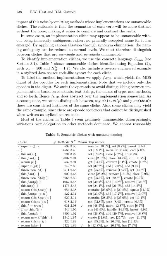
238 E.W. Høst and B.M. Østvold
impact of this noise by omitting methods whose implementations are unnameablecliches. The rationale is that the semantics of each verb will be more distinctwithout the noise, making it easier to compare and contrast the verbs.
In some cases, an implementation cliche may appear to be unnameable with-out being inherently ambiguous: rather, no generally accepted name for it hasemerged. By applying canonicalisation through synonym elimination, the nam-ing ambiguity can be reduced to normal levels. We must therefore distinguishbetween cliches that are seemingly and genuinely unnameable.
To identify implementation cliches, we use the concrete language LJava (seeSection 3.1). Table 5 shows unnameable cliches identified using Equation (2),with φcl = 500 and HN
cl = 1.75. We also include a reverse engineered examplein a stylized Java source code-like syntax for each cliche.
To label the method implementations we apply fMD5, which yields the MD5digest of the opcodes for each implementation. Note that we include only theopcodes in the digest. We omit the operands to avoid distinguishing between im-plementations based on constants, text strings, the names of types and methods,and so forth. Hence fMD5 does abstract over the implementation somewhat. Asa consequence, we cannot distinguish between, say, this.m(p) and p.m(this):these are considered instances of the same cliche. Also, some cliches may yieldthe same example, since there are opcode sequences that cannot be distinguishedwhen written as stylized source code.
Most of the cliches in Table 5 seem genuinely unnameable. Unsurprisingly,variations over delegation to other methods dominate. We cannot reasonably
Table 5. Semantic cliches with unstable naming
Cliche # Methods HN Retain Top names{ super.m(); } 539 3.50 remove [10.6%], set [8.7%], insert [6.5%]{ } 14566 3.40 set [18.1%], initialize [8.4%], end [7.8%]{ this.m(); } 794 3.22 set [18.5%], close [7.2%], do [6.2%]{ this.f .m(); } 2007 2.94 clear [20.7%], close [13.2%], run [11.7%]{ return p; } 532 2.94 get [34.4%], convert [7.1%], create [4.7%]{ super.m(p); } 742 2.69 set [32.2%], end [12.0%], add [9.4%]{ throw new E(); } 3511 2.68 get [25.4%], remove [17.2%], set [14.8%]{ this.f .m(); } 900 2.65 clear [28.2%], remove [16.1%], close [9.9%]{ throw new E(s); } 5666 2.59 get [25.9%], set [22.3%], create [10.7%]{ this.f .m(p); } 1062 2.48 set [39.2%], add [14.8%], remove [12.0%]{ this.m(p); } 1476 2.45 set [24.4%], end [21.7%], add [14.2%]{ return this.f .m(p); } 954 2.38 contains [25.9%], is [20.8%], equals [11.1%]{ this.f .m(p1, p2); } 522 2.34 set [33.0%], add [17.2%], remove [13.0%]{ return this.f .m(p); } 929 2.14 contains [28.3%], is [25.0%], get [11.1%]{ return this.m(p); } 618 2.14 get [52.8%], post [8.4%], create [6.3%]{ this.f = true; } 631 2.08 � set [48.5%], mark [12.8%], start [6.7%]{ C.m(this.f); } 544 1.96 run [46.9%], handle [14.3%], insert [9.9%]{ this.f .m(p); } 3906 1.92 set [36.8%], add [29.7%], remove [16.8%]{ return new C(this); } 1540 1.87 � create [34.6%], get [25.7%], new [11.9%]{ return this.m(); } 520 1.83 get [45.0%], is [20.0%], has [12.5%]{ return false; } 6322 1.83 � is [52.8%], get [20.1%], has [7.3%]

Canonical Method Names for Java 239
provide a name for such methods without considering the names of the methodsbeing delegated to. There are also some examples of “unimplemented” methods;for instance { throw new E(); } or the empty method { }. We believe that inmany cases, the presence of these methods will be required by the compiler (forinstance to satisfy some interface), but in practice, they will never be invoked.
Table 5 also contains three cliches that we deem only seemingly unnameable.This is based on a subjective judgement that they could be relatively consistentlynamed, given a more well-defined vocabulary. These have been marked as beingretained, meaning they are included in the analysis. The others are omitted.
5 Addressing Synonyms
To address the problem of synonyms, we employ the formula opt fromSection 3.3. We use opt to mechanically identify likely synonyms in the cor-pus described in Section 4, and then to attempt unsupervised elimination ofsynonyms.
5.1 Identifying Synonyms
Compared to each of the common verbs in the corpus, the other verbs will rangefrom synonyms or “semantic siblings” to the opposite or unrelated. To find theverbs that are semantically most similar to each verb, we calculate the valuefor opt when merging the nominal corpus of each verb with the nominal corpusof each of the other verbs. The verbs that yield the lowest value for opt areconsidered synonym candidates.
It is more likely that two verbs are genuine synonyms if they reciprocally holdeach other to be synonym candidates. When we identify such pairs of synonymcandidates, we find that clusters emerge among the verbs, as shown in Figure 4.
Several of the clusters could be labelled, for instance as questions, initialisers,factories, runners, checkers and terminators. This suggests that these clustershave a “topic”. It does not imply that all the verbs in each cluster could bereplaced by a single verb, however. For instance, note that in the factory cluster,create and make are indicated as synonym candidates, as are create and new,but new and make are not. An explanation could be that create has a broaderuse than new and make.
We also see that there are two large clusters that appear to have more than onetopic. We offer two possible explanations. First, polysemous verbs will tie togetherotherwise unrelated topics (see Section 2). In the largest cluster, for instance, wefind a mix of verbs associated with I/O and verbs that handle collections. In thiscase, append is an example of a polysemous verb used in both contexts. Second,we may lack attributes to distinguish appropriately between the verbs.
5.2 Eliminating Synonyms
To eliminate synonyms, we iterate over the collection of verbs. We greedily selectthe elimination that yields the best immediate benefit for opt in each iteration.

240 E.W. Høst and B.M. Østvold
contains
has
iscan
matches
test
run
verify
check
size
hash
release close
clear
stopflush
reset
make
create
new
setup
initialize
init
start
begin process
handle
notify
saveupdate
post
store
end
add
append put
warning fataldebug
log
write
fill
send push
remove
register
Factories Initialisers Questions
Terminators
Runners Checkers
Fig. 4. Clusters of synonym candidates. Clusters with a single topic are labelled.
Table 6. Mechanical elimination of synonyms
Run Canonical verb (cv) Old verbs |C/cv| Sum ΔHSagg ΔHN
agg Δopt
1 is has+is 49041 6820+42221 0.00269 -0.02270 -0.011522 is can+is 51649 2608+49041 0.00178 -0.01148 -0.004093 add remove+add 43241 16172+27069 0.00667 -0.03004 -0.002374 init initialize+init 11026 3568+7458 0.00149 -0.00743 -0.001265 close stop+close 5025 1810+3215 0.00074 -0.00348 -0.000406 create make+create 38140 4940+33200 0.00363 -0.01525 -0.000217 close flush+close 5936 911+5025 0.00061 -0.00266 -0.000148 reset clear+reset 5849 2901+2948 0.00100 -0.00421 -0.000079 write log+write 13659 1775+11884 0.00131 -0.00547 -0.00004

Canonical Method Names for Java 241
Table 7. Manual elimination of synonyms
Canonical verb (cv) Old verbs |C/cv| Sum ΔHSagg ΔHN
agg Δopt
clone clone+copy 4732 2595+2137 0.00271 -0.00147 0.00979execute execute+invoke 4947 2997+1950 0.00197 -0.00229 0.00589verify check+verify 8550 7440+1110 0.00126 -0.00298 0.00223stop stop+end 4814 1810+3004 0.00126 -0.00283 0.00242write write+log+dump 15987 11884+1775+2328 0.00420 -0.01109 0.00635start start+begin 5485 4735+750 0.00081 -0.00200 0.00135init init+initialize 11026 7458+3568 0.00149 -0.00743 -0.00126error error+fatal 1531 1116+415 0.00027 -0.00088 0.00023create create+new+make 45565 33200+7425+4940 0.00901 -0.03588 0.00152
We assume that beneficial eliminations will occur eventually, and that the orderof eliminations is not important. We only label a synonym candidate as “gen-uine” if the value for opt decreases; the iteration stops when no more genuinecandidates can be found. For comparison, we also perform manual eliminationof synonyms, based on a hand-crafted list of synonym candidates.
The results of mechanical synonym elimination are shown in Table 6. Notethat the input to the elimination algorithm is the output given by the precedingrun of the algorithm. For the first run, the input is the original “purified” corpusdescribed in Section 4, whereas for the second, the verb has has been eliminated,and the original nominal corpora for has and is have been merged.
The elimination of has is interesting: it is considered the most beneficialelimination by opt, yet as Java programmers, we would hesitate to eliminateit. The subtle differences in meaning between all “boolean queries” (is, has,can, supports and so forth) are hard to discern at the implementation level.Indeed, we would often accept method names with different verbs for the sameimplementation: hasChildren and isParent could be equally valid names. Thiskind of nominal flexibility is arguably beneficial for the readability of code.
It is easier to see that either init or initialize should be eliminated: there isno reason for the duplication. Eliminating make and using create as a canonicalverb for factory methods also seems reasonable. Similarly, the suggestion to usewrite instead of log is understandable — however, one could argue that log isuseful because it is more precise than the generic write.
There seems to be quite a few verbs for “termination code”; some of these verbsmight be redundant. The unsupervised elimination process identifies flush, stopand close as candidates for synonym elimination. However, we find it unaccept-able: certainly, flush and close cannot always be used interchangeably. In ourcoarse-grained semantic model, we lack the “semantic clues” to distinguish be-tween these related, yet distinct verbs.
The suggestion to combine add and remove is also problematic, again showingthat the approach has some limitations. Both add and remove typically involvecollections of items, perhaps including iteration (which is captured by the Con-tains loop attribute). The crucial distinction between the two operations willoften be hidden inside a call to a method in the Java API. Even if we were to

242 E.W. Høst and B.M. Østvold
observe the actual adding or removing of an item, this might involve increment-ing or decrementing a counter, which is not captured by our model.
Table 7 shows the result of the manual elimination of synonyms. We notethat only the elimination of initialize yields a decreased value for opt —apparently, we are not very good at manual synonym identification! However, itmay be that the requirement that opt should decrease is too strict. Indeed, wefind that many of our candidates are present in the clusters shown in Figure 4.This indicates that there is no deep conflict between our suggestions and theunderlying data.
5.3 Canonicalisation
Overall, we note that our approach succeeds in finding relevant candidates forsynonym elimination. However, it is also clear that the elimination must be su-pervised by a programmer. We therefore suggest using Figure 4 as a startingpoint for manual canonicalisation of verbs in method names. Canonicalisationshould entail both eliminating synonyms and providing a precise definition, ra-tionale and use cases for each verb.
6 Related Work
Gil and Maman [13] introduce the notion of machine-traceable patterns, in orderto identify so-called micro patterns; machine-traceable implementation patternsat the class level. When we model the semantics of method implementationsusing hand-crafted bytecode predicates, we could in principle discern “nano pat-terns” at the method implementation level. According to Gamma et al. [14],however, a pattern has four essential elements: name, problem, solution andconsequences. Though we do identify some very commonly used implementationcliches, we do not attempt to interpret and structure these cliches. Still, Singeret al. [15] present their own expanded set of bytecode predicates under the label“fundamental nano patterns”, where the term “pattern” must be understood ina broader, more colloquial sense.
Collberg et al. [16] present a large set of low-level statistics from a corpus ofJava applications, similar in size to ours. Most interesting to us are the statisticsshowing k-grams of opcodes, highlighting the most commonly found opcodesequences. This is similar to the implementation cliches we find in our work.Unfortunately, the k-grams are not considered as logical entities, so a common2-gram will often appear as part of a common 3-gram as well.
Similar in spirit to our work, Singer and Kirkham [17] find a correlation be-tween certain commonly used type name suffixes and some of Gil and Maman’smicro patterns. Pollock et al. [18] propose using “natural language program anal-ysis”, where natural language clues found in comments and identifiers are used toaugment and guide program analyses. Tools for program navigation and aspectmining have been developed [19,20] based on this idea. Ma et al. [21] exploit thefact that programmers usually choose appropriate names in their code to guidesearches for software artefacts.

Canonical Method Names for Java 243
The quality of identifiers is widely recognised as important. Deißenböck andPizka [22] seek to formalise two quality metrics, conciseness and consistency,based on a bijective mapping between identifers and concepts. Unfortunately,the mapping must be constructed by a human expert. Lawrie et al. [23] seek toovercome this problem by deriving syntactic rules for conciseness and consistencyfrom the identifiers themselves. This makes the approach much more applicable,but introduces the potential for false positives and negatives.
7 Conclusion and Further Work
The ambiguous vocabulary of verbs used in method names makes Java programsless readable than they could be. We have identified redundancy, coarseness andvagueness as the problems to address. In this paper, we focussed on redundancy,where more than one verb is used in the same meaning. We looked at the iden-tification and elimination of synonymous verbs as a means towards this goal.
We found that we were indeed able to identify reasonable synonym candi-dates for many verbs. To select the genuine synonyms among the candidateswithout human supervision is more problematic. The abstract semantics we usefor method implementations is sometimes insufficient to capture important nu-ances between verbs. A more sophisticated model that takes into account in-voked methods, either semantically (by interprocedural analysis of bytecode) ornominally (by noting the names of the invoked methods) might overcome someof these problems. Realistically, however, the perspective of a programmer willprobably still be needed. A more fruitful way forward may be to use the identifiedsynonym candidates as a starting point for a manual process where a canonicalset of verbs is given precise definitions, and the rest are discouraged from use.
Addressing the problem of coarseness is a natural counterpart to the topicof this paper. Coarseness manifests itself in polysemous verbs, that is, verbsthat have more than a single meaning. Polysemous verbs could be addressedby investigating the semantics of the methods that constitute a nominal corpusC/n. The intuition is that polysemous uses of n will reveal itself as clustersof semantically similar methods. Standard data clustering techniques could beapplied to identify such polysemous clusters. If a nominal corpus were foundto contain polysemous clusters, we could investigate the effect of renaming themethods in one of the clusters. This would entail splitting the original nominalcorpus C/n in two, C/n and C/n′. The effect of splitting the corpus could bemeasured, for instance by applying the formula opt from Section 3.3.
References
1. Abelson, H., Sussman, G.J.: Structure and Interpretation of Computer Programs,2nd edn. MIT Electrical Engineering and Computer Science. MIT Press, Cam-bridge (1996)
2. Eierman, M.A., Dishaw, M.T.: The process of software maintenance: a comparisonof object-oriented and third-generation development languages. Journal of SoftwareMaintenance and Evolution: Research and Practice 19(1), 33–47 (2007)

244 E.W. Høst and B.M. Østvold
3. Collar, E., Valerdi, R.: Role of software readability on software development cost.In: Proceedings of the 21st Forum on COCOMO and Software Cost Modeling,Herndon, VA (October 2006)
4. von Mayrhauser, A., Vans, A.M.: Program comprehension during software main-tenance and evolution. Computer 28(8), 44–55 (1995)
5. Lawrie, D., Morrell, C., Feild, H., Binkley, D.: Effective identifier names for com-prehension and memory. ISSE 3(4), 303–318 (2007)
6. Martin, R.C.: Clean Code. Prentice-Hall, Englewood Cliffs (2008)7. Beck, K.: Implementation Patterns. Addison-Wesley Professional, Reading (2007)8. Høst, E.W., Østvold, B.M.: The programmer’s lexicon, volume I: The verbs. In:
Proceedings of the 7th IEEE International Working Conference on Source CodeAnalysis and Manipulation (SCAM 2007), pp. 193–202. IEEE Computer Society,Los Alamitos (2007)
9. Høst, E.W., Østvold, B.M.: The java programmer’s phrase book. In: Gašević, D.,Lämmel, R., Van Wyk, E. (eds.) SLE 2008. LNCS, vol. 5452, pp. 322–341. Springer,Heidelberg (2009)
10. Høst, E.W., Østvold, B.M.: Debugging method names. In: Drossopoulou, S. (ed.)ECOOP 2009. LNCS, vol. 5653, pp. 294–317. Springer, Heidelberg (2009)
11. Steels, L.: The recruitment theory of language origins. In: Lyon, C., Nehaniv, C.L.,Cangelosi, A. (eds.) Emergence of Language and Communication, pp. 129–151.Springer, Heidelberg (2007)
12. Cover, T.M., Thomas, J.A.: Elements of Information Theory, 2nd edn. Wiley Seriesin Telecommunications. Wiley, Chichester (2006)
13. Gil, J., Maman, I.: Micro patterns in Java code. In: Proceedings of the 20th ACMSIGPLAN Conference on Object-Oriented Programming, Systems, Languages, andApplications (OOPSLA 2005), pp. 97–116. ACM, New York (2005)
14. Gamma, E., Helm, R., Johnson, R., Vlissides, J.: Design Patterns. Addison-Wesley,Boston (1995)
15. Singer, J., Brown, G., Lujan, M., Pocock, A., Yiapanis, P.: Fundamental nano-patterns to characterize and classify Java methods. In: Proceedings of the 9thWorkshop on Language Descriptions, Tools and Applications (LDTA 2009), pp.204–218 (2009)
16. Collberg, C., Myles, G., Stepp, M.: An empirical study of Java bytecode programs.Software Practice and Experience 37(6), 581–641 (2007)
17. Singer, J., Kirkham, C.: Exploiting the correspondence between micro patterns andclass names. In: Proceedings of the 8th IEEE International Working Conference onSource Code Analysis and Manipulation (SCAM 2008), pp. 67–76. IEEE ComputerSociety, Los Alamitos (2008)
18. Pollock, L.L., Vijay-Shanker, K., Shepherd, D., Hill, E., Fry, Z.P., Maloor, K.:Introducing natural language program analysis. In: Das, M., Grossman, D. (eds.)Proceedings of the 7th ACM SIGPLAN-SIGSOFT Workshop on Program Analysisfor Software Tools and Engineering (PASTE 2007), pp. 15–16. ACM, New York(2007)
19. Shepherd, D., Pollock, L.L., Vijay-Shanker, K.: Towards supporting on-demandvirtual remodularization using program graphs. In: Filman, R.E. (ed.) Proceedingsof the 5th International Conference on Aspect-Oriented Software Development(AOSD 2006), pp. 3–14. ACM, New York (2006)
20. Shepherd, D., Fry, Z.P., Hill, E., Pollock, L., Vijay-Shanker, K.: Using naturallanguage program analysis to locate and understand action-oriented concerns. In:Proceedings of the 6th International Conference on Aspect-Oriented Software De-velopment (AOSD 2007), pp. 212–224. ACM, New York (2007)

Canonical Method Names for Java 245
21. Ma, H., Amor, R., Tempero, E.D.: Indexing the Java API using source code. In:Proceedings of the 19th Australian Software Engineering Conference (ASWEC2008), pp. 451–460. IEEE Computer Society, Los Alamitos (2008)
22. Deißenböck, F., Pizka, M.: Concise and consistent naming. In: Proceedings of the13th IEEE International Workshop on Program Comprehension (IWPC 2005), pp.97–106. IEEE Computer Society, Los Alamitos (2005)
23. Lawrie, D., Feild, H., Binkley, D.: Syntactic identifier conciseness and consistency.In: 6th IEEE International Workshop on Source Code Analysis and Manipulation(SCAM 2006), pp. 139–148. IEEE Computer Society, Los Alamitos (2006)

Subjective-CBringing Context to Mobile Platform Programming
Sebastián González, Nicolás Cardozo, Kim Mens,Alfredo Cádiz, Jean-Christophe Libbrecht, and Julien Goffaux
Computing Science Engineering Pole, ICTEAM, UCLouvainPlace Sainte-Barbe 2, 1348 Louvain-la-Neuve, Belgium
Abstract. Thanks to steady advances in hardware, mobile computingplatforms are nowadays much more connected to their physical and logi-cal environment than ever before. To ease the construction of adaptableapplications that are smarter with respect to their execution environ-ment, the context-oriented programming paradigm has emerged. How-ever, up until now there has been no proof that this emerging paradigmcan be implemented and used effectively on mobile devices, probably thekind of platform which is most subject to dynamically changing contexts.In this paper we study how to effectively realise core context-orientedabstractions on top of Objective-C, a mainstream language for mobiledevice programming. The result is Subjective-C, a language which goesbeyond existing context-oriented languages by providing a rich encodingof context interdependencies. Our initial validation cases and efficiencybenchmarks make us confident that context-oriented programming canbecome mainstream in mobile application development.
1 Introduction
New computing platforms are interrelated to their physical execution environ-ment through all kinds of sensors that are able to measure location, orientation,movement, light, sound, temperature, network signal strength, battery chargelevel, and so forth. At the logical level, even traditional desktop and server plat-forms are getting exposed to richer environments in which they can find networkservices of all sorts. Both at the physical and logical levels, the live environmentin which applications execute is acquiring a central role. If equipped with higherlevels of context-driven adaptability, software systems can become smarter withrespect to their environment and to user needs, exhibit emergent properties, beresilient in the face of perturbations, and generally fit better in the technicalecosystem in which they are used.
Unfortunately, most software systems do not meet the high adaptability ex-pectations that stem naturally from their connectedness to their environment.Most applications exhibit fixed functionality and are seldom aware of changingcontexts to adapt their behaviour accordingly. Many chances of delivering im-proved services to users and network peers are thus missed. We hypothesise thata major reason for this lack of adaptability is the unavailability of appropriate
B. Malloy, S. Staab, and M. van den Brand (Eds.): SLE 2010, LNCS 6563, pp. 246–265, 2011.c© Springer-Verlag Berlin Heidelberg 2011

context-aware programming languages and related tool sets. Current program-ming technology does not put programmers in the right state of mind, nor doesit provide adequate abstractions, to program context-aware applications.
Starting from this observation, Context-Oriented Programming (COP) hasbeen introduced as a novel programming paradigm which eases the developmentof adaptable behaviour according to changing contexts [4,9]. COP offers an al-ternative to hard-coded conditional statements and special design patterns toencode context-dependent behaviour. COP thereby renders code more reusableand maintainable. Unfortunately, current COP languages do not run on mobileplatforms —probably the kind of platform for which context is most relevant,thus offering the most promising possibilities for development of context-awareapplications. Furthermore, COP languages still lack dedicated facilities to modelthe knowledge of the situation in which applications execute.
With the aim of having a COP language that runs on a mobile platform, weset out to develop an extension of Objective-C, one of the most widespread pro-gramming languages for mobile systems. The result is Subjective-C, a new COPlanguage extension aimed at easing the construction of context-aware mobile ap-plications. In Subjective-C, object behaviour depends on the context in which itexecutes. Hence, observed behaviour is not absolute or objective, but rather of amore relative or subjective nature [17]. A minimum amount of computational re-flection available in Objective-C suffices to add the necessary abstractions whichallow the straightforward expression of context-specific behaviour.
Subjective-C is not a mere reimplementation of the concepts behind mainCOP languages like Ambience [8] and ContextL [4]. Subjective-C goes beyondthe simple inheritance relationships that are possible between context objects inAmbience, and between layer classes in ContextL, by providing explicit meansto encode more advanced interdependencies between contexts. Not only doesSubjective-C allow for more kinds of dependencies, but also they can be ex-pressed in a domain-specific language developed especially for this purpose, mak-ing the declaration of such dependencies more readable.
To validate Subjective-C, we implemented three proof-of-concept applica-tions that run on actual smartphones. These case studies showed the feasibility ofprogramming context-aware applications using subjective programming abstrac-tions, with a noticeable increase in software understandability, maintainabilityand extensibility. Furthermore, efficiency benchmarks show that the performanceimpact of COP abstractions in Subjective-C is negligible, to the point that insome cases it can even improve performance.
The remainder of this paper is organised as follows. Section 2 introduces thebasics of context-oriented programming in Subjective-C. Section 3 goes on toexplain context relations in detail. Section 4 presents the reflective implementa-tion technique we used to add a subjective layer on top of Objective-C. Section 5briefly presents three validation cases we conducted to assess the advantages anddisadvantages of Subjective-C. Section 6 reports on the efficiency benchmarks wecarried out. Section 7 discusses limitations and future work. We present relatedwork in Section 8, and draw the paper to a close in Section 9.
Subjective-C 247

2 Context-Oriented Programming in Subjective-C
Context-Oriented Programming (COP) is an emerging programming paradigmin which contextual information plays a central role in the definition of appli-cation behaviour [4,8,18]. The essence of COP is the ability to overlay adaptedbehaviour on top of existing default behaviour, according to the circumstances inwhich the software is being used. Such adaptations are meant to gracefully adjustthe service level of the application, following detected changes in the executionenvironment. COP languages provide dedicated programming abstractions toenable this behavioural adaptability to changing contexts. This section presentsthe COP core on which Subjective-C is based. The fundamental language con-structs are introduced progressively, as core mechanisms are explained.
2.1 General System Architecture
Subjective-C has been conceived for a fairly straightforward system architecture,illustrated in Fig. 1. Context information is received mainly from two sources.Firstly, there is a context discovery module which collects sensor data to makesense of the physical world in which the system is running, and also monitors net-work services to make sense of the logical environment. Logical context changescan also be signalled internally by the running application, for instance whenswitching to secure or logging mode. Having all context changes at hand, thecontext management module analyses the current situation and might chose toprioritise some of the context changes, defer others for later application, dropcontext changes that have become outdated, and solve possible conflicts stem-ming from contradictory information and adaptation policies (for instance, in-creasing fan speed due to overheating, versus reducing fan speed due to lowbattery charge). It then commits a coherent set of changes to the active contextrepresentation, which directly affects application behaviour.
Sensors Actuators
contextinformation arbitrated
context changes
context effect
external internal
ActiveContext
Context Management
Context Discovery
Application Behaviour
World
Fig. 1: General architecture for context-aware systems
248 S. Gonzalez et al.
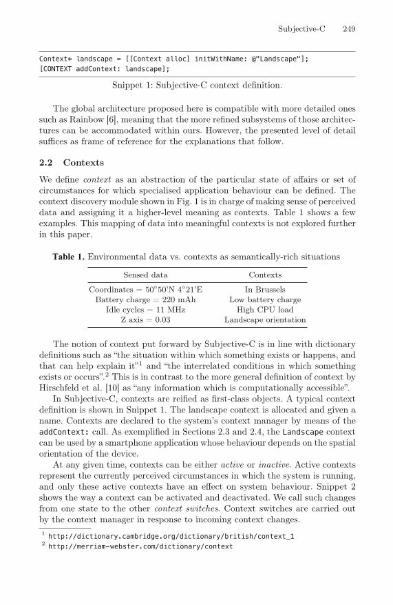
Context* landscape = [[Context alloc] initWithName: @"Landscape"];[CONTEXT addContext: landscape];
Snippet 1: Subjective-C context definition.
The global architecture proposed here is compatible with more detailed onessuch as Rainbow [6], meaning that the more refined subsystems of those architec-tures can be accommodated within ours. However, the presented level of detailsuffices as frame of reference for the explanations that follow.
2.2 Contexts
We define context as an abstraction of the particular state of affairs or set ofcircumstances for which specialised application behaviour can be defined. Thecontext discovery module shown in Fig. 1 is in charge of making sense of perceiveddata and assigning it a higher-level meaning as contexts. Table 1 shows a fewexamples. This mapping of data into meaningful contexts is not explored furtherin this paper.
Sensed data Contexts
Coordinates = 50◦50’N 4◦21’E In BrusselsBattery charge = 220 mAh Low battery charge
Idle cycles = 11 MHz High CPU loadZ axis = 0.03 Landscape orientation
Table 1: Environmental data vs. contexts as semantically-rich situations
The notion of context put forward by Subjective-C is in line with dictionarydefinitions such as “the situation within which something exists or happens, andthat can help explain it”1 and “the interrelated conditions in which somethingexists or occurs”.2 This is in contrast to the more general definition of context byHirschfeld et al. [10] as “any information which is computationally accessible”.
In Subjective-C, contexts are reified as first-class objects. A typical contextdefinition is shown in Snippet 1. The landscape context is allocated and given aname. Contexts are declared to the system’s context manager by means of theaddContext: call. As exemplified in Sections 2.3 and 2.4, the Landscape contextcan be used by a smartphone application whose behaviour depends on the spatialorientation of the device.
At any given time, contexts can be either active or inactive. Active contextsrepresent the currently perceived circumstances in which the system is running,and only these active contexts have an effect on system behaviour. Snippet 2shows the way a context can be activated and deactivated. We call such changesfrom one state to the other context switches. Context switches are carried outby the context manager in response to incoming context changes.1 http://dictionary.cambridge.org/dictionary/british/context_12 http://merriam-webster.com/dictionary/context
Subjective-C 249

[CONTEXT activateContextWithName: @"Landscape"];[CONTEXT deactivateContextWithName: @"Landscape"];
Snippet 2: Context activation and deactivation.
#context Landscape- (NSString*)getText() {return [NSString stringWithString:@"Landscape view"];
}
Snippet 3: Context-specific method definition.
2.3 Contextual Behaviour
Subjective-C concentrates on algorithmic adaptation, allowing the definitionof behaviour that is specific to certain execution contexts. Programmers canthereby define behaviour that is more appropriate to those particular contextsthan the application’s default behaviour.
In Subjective-C, defining context-dependent behaviour is straightforward.Adapted behaviour can be defined at a very fine granularity level, namely ona per-method basis. To define methods that are specific to a context, a simpleannotation suffices. Snippet 3 illustrates a typical context-specific method defini-tion. The #context annotation lets Subjective-C know that the getText methoddefinition is specific to the given named context. This version of getText shouldbe invoked only when the device is in Landscape position. The method is notto be applied under any other circumstances. The general EBNF syntax forcontext-specific method definitions is as follows:
#context ([!]contextName)+methodDefiniton
This is one of the two syntactic extensions Subjective-C lays over Objective-C;the other one is explained in Section 2.4. As can be observed in this generalform, it is possible to specialise a method on more than one context. It sufficesto provide multiple context names after the #context keyword that precedesthe method definition. The method is applicable only when all its correspondingcontexts are active simultaneously.
As a convenience, Subjective-C introduces method specialisation on the com-plement of a context by means of the negation symbol (!). Such complementarymethod specialisations mean that the method is applicable only when the givencontext is inactive. Complementary specialisations serve as a shortcut to ex-plicitly defining a complementary context object and associated managementpolicies.
2.4 Behaviour Reuse
For most cases it is of little use to provide a means to define context-specificbehaviour but no means to invoke at some point the original default behaviour
250 S. Gonzalez et al.

1 @implementation UILabel (color)2 #context Landscape3 - (void)drawTextInRect:(CGRect)rect{4 self.textColor = [UIColor greenColor];5 [superContext drawTextInRect:rect];6 }7 @end
Snippet 4: Sample use of superContext construct.
as part of the adaptation. The absence of such a mechanism would lead to thereimplementation of default behaviour in overriding context-specific methods,resulting in code duplication. Subjective-C therefore permits the invocation ofoverridden behaviour through the superContext construct, which has two generalforms:
[superContext selector];[superContext keyword: argument ...];
Next to the #context construct explained in Section 2.3, superContext is thesecond syntactic extension of Subjective-C over Objective-C.
Snippet 4 shows an example in which the colour of a label widget changesto green when the orientation of the host device is horizontal (i.e., when thecontext Landscape is active). This example shows in passing that it is possible tomodify the behaviour of stock library objects such as UILabel, which have beendeveloped independently, and for which adaptations such as the one in Snippet 4were not foreseen. It is possible to layer adaptations on top of any existing object,without access to its source code. This is made possible by Objective-C’s openclasses and categories.
3 Context Relations
Subjective-C allows the explicit encoding of context relationships. These rela-tionships impose constraints among contexts, which either impede activation orcause cascaded activations and deactivations of related contexts. A failure torespect the natural relationships between contexts could lead to unexpected,undesired, or erroneous application behaviour. All behaviour described in thissection is part of the context management subsystem illustrated in Fig. 1.
When a context is switched, the system has to inspect all relations involv-ing the context, checking if the change is consistent with imposed constraints,and performing other switches triggered by the requested one. This section con-cisely specifies the different relation types and their effect on context switchingthrough four main methods that any context must implement: canActivate,canDeactivate, activate and deactivate.
To deal with multiple activations, every context has an activation counter,which the activate method increases, and deactivate decreases (if positive).Only when the counter falls down to zero is the context actually removed fromthe active context representation.
Subjective-C 251

3.1 Weak Inclusion Relation
Sometimes the activation of a context implies the activation of a related one.For example, if domain analysis yields that cafeterias are usually noisy, then theactivation of the Cafeteria context should induce the activation of the Noisycontext. We say that the former context includes the latter one. However, theinclusion is a weak one in the sense that the contrapositive does not necessarilyhold. Even though there might be no noise, the device might still be locatedin a cafeteria. The key here is that cafeterias are usually, though not always,noisy. Fig. 2 shows the definition of weak inclusion relations. Activating (resp.deactivating) the source context Cafeteria implies activating (resp. deactivat-ing) the target context Noisy. The source context can always be activated anddeactivated. Conversely, because it is a weak inclusion relation, the target con-text Noisy is not constrained at all by the source context Cafeteria. The targetcontext can be activated and deactivated anytime, without consequences on theactivation status of the source context.
Cafetaria Noisy
message source behaviour target behaviourcanActivate YES YES
canDeactivate YES YESactivate target activate —
deactivate target deactivate —
Fig. 2: Weak inclusion relation specification
3.2 Strong Inclusion Relation
In a strong inclusion relation, the activation of the source context implies theactivation of the target context, as in weak inclusions. Additionally, the contra-positive holds: deactivation of the target implies automatically a deactivation ofthe source. For example, if the current location is Brussels, then necessarily thedevice is also located in Belgium. If the current location is not Belgium, then it iscertainly also not Brussels. Fig. 3 shows the definition of such strong inclusionrelations. As illustrated by the example, this kind of relation can be used tosignal that a specific context is a particular case of a more general one.
Brussels Belgium
message source behaviour target behaviourcanActivate target canActivate YES
canDeactivate YES source canDeactivateactivate target activate —
deactivate target deactivate source deactivate
Fig. 3: Strong inclusion relation specification
252 S. Gonzalez et al.

3.3 Exclusion Relation
Some contexts are mutually exclusive. For instance, a network connection sta-tus cannot be Online and Offline simultaneously, and the battery charge levelcannot be high and low at the same time (note however that it makes sense fortwo exclusive contexts such as LowBattery and HighBattery to be simultane-ously inactive). This motivates the introduction of exclusion relations betweencontexts, specified in Fig. 4. Note that the exclusion relation is symmetrical.
LowBattery HighBattery
message source behaviour target behaviourcanActivate target isInactive source isInactive
canDeactivate YES YESactivate — —
deactivate — —
Fig. 4: Exclusion relation specification
3.4 Requirement Relation
Sometimes certain contexts require other contexts to function properly. For in-stance, a high-definition video decoding context HDVideo might work only whenHighBattery is active. If HighBattery is inactive, then HDVideo cannot be acti-vated either. Fig. 5 specifies this requirement relation between contexts.
HDVideo HighBattery
message source behaviour target behaviourcanActivate target isActive YES
canDeactivate YES source canDeactivateactivate — —
deactivate — source deactivate
Fig. 5: Requirement relation specification
3.5 Context Declaration Language
For non-trivial scenarios, the programmatic definition of contexts and their rela-tions in Subjective-C can become verbose. As an example, consider the relativelycomplex code to create just two contexts and an exclusion relation between them,shown in Snippet 5 (left).
Observing that it is cumbersome to describe context settings programmati-cally, we developed a small Domain-Specific Language (DSL) for this purpose.
Subjective-C 253

Context* on = [[Context alloc] initWithName:@"Online"];Context* off = [[Context alloc] initWithName:@"Offline"];[CONTEXT addContext:on];[CONTEXT addContext:off];[on addExclusionLinkWith:off];
Contexts:OnlineOfflineLinks:Online >< Offline
Snippet 5: Manual creation of contexts and their relations in Subjective-C (left)versus equivalent code using the context declaration language (right).
In this DSL, contexts are declared simply by naming them, and their relationsestablished by means of the following textual notation:
– Weak Inclusion: A -> B– Strong Inclusion: A => B– Exclusion: A >< B– Requirement: A =< B
The right side of Snippet 5 shows how the context set-up on the left sideis obtained using the context declaration language. This language permits theedition of contexts and their relations with all the advantages brought by aDSL: it has a more intuitive notation that can be understood even by non-programmers, it results in more succinct code, and eases rapid prototyping.3
In its current version, Subjective-C does not check inconsistencies amongcontext relationships at the moment they are created (for example if A => Bon the one hand but A >< B on the other); as mentioned earlier, it checks forinconsistencies when contexts are switched, preventing any contradictory change.Support for earlier checks is part of our future work.
4 Implementation
Most existing COP implementations exploit meta-programming facilities such assyntactic macros and computational reflection provided by the host object modelto modify method dispatch semantics, thereby achieving dynamic behaviour se-lection. It is no surprise that these implementations have been laid on top ofdynamic languages that permit such level of flexibility.
For approaches based on more static languages such as ContextJ for Java [1],existing implementations use a dedicated compiler. This is also the case ofSubjective-C, in which the compiler is just a small language transformer to plainObjective-C. However, Subjective-C does not intercept method dispatch as otherapproaches do. Rather, it precomputes the most specific methods that becomeactive right after every context switch. This original implementation technique,explained in this section, is possible thanks to some of the dynamic featuresoffered by Objective-C. Section 6 presents an efficiency comparison of the twoapproaches (method precomputation versus method lookup modification).3 A script integrated in the build process of the IDE parses the context declaration
files written in the DSL and translates them into equivalent Objective-C code. Theresult is compiled together with regular source code files.
254 S. Gonzalez et al.

@implementation UILabel (color)- (void)Context_Landscape_drawTextInRect:(CGRect)rect {self.textColor = [UIColor greenColor];SUPERCONTEXT(@selector(drawTextInRect:), [self drawTextInRect:rect]);
}@end
Snippet 6: Context-specific version of UILabel’s drawTextInRect: methodtranslated to plain Objective-C.
[MANAGERaddMethod:@selector(Context_Landscape_drawTextInRect:)forClass:[UILabel class]forContextNames: [NSSet setWithObjects: @"Landscape", nil]withDefautSelector:@selector(drawTextInRect:)withPriority:0];
Snippet 7: Registration of a context-specific method.
4.1 Method Translation
Context-specific methods, explained in Section 2.3, have the same signature asthe original method containing the default implementation. For instance, thedrawTextInRect: method from Snippet 4 has the same signature as the stan-dard method furnished by Apple’s UIKit framework.4 The intention of adaptedmethods is precisely to match the same messages the original method matches,but then exhibit different behaviour in response to the message.
To disambiguate method identifiers that have been overloaded for multiplecontexts, and thus distinguish between the different context-dependent imple-mentations sharing a same signature, Subjective-C uses name mangling. Namemangling is a well-known technique in which identifiers are decorated with addi-tional information from the method’s signature, class, namespace, and possiblyothers pieces of information to render the decorated name unique. In Subjective-C, the selector of any context-specific method is mangled by prefixing the Con-text keyword, followed by the name of all contexts on which the method hasbeen specialised. The name of complementary contexts (explained in Section 2.3)is prefixed with NOT. The different name parts are separated by underscores. Asan example, Snippet 6 shows how the name of the drawTextInRect: methodfrom Snippet 4 is mangled. The snippet also shows the translation of the super-Context construct, discussed further in Section 4.3.
The different method versions are registered to the context manager by auto-matically generated code, shown in Snippet 7. The priority index lets the contextmanager order method implementations to avoid ambiguities. This ordering isdiscussed further in Section 7.
4 UIKit provides the classes needed to manage an application’s user interface in iOS.
Subjective-C 255

Method current_method =class_getInstanceMethod(affectedClass, defaultMethodName);Method selected_method =class_getInstanceMethod(affectedClass, mangledMethodName);method_setImplementation(current_method, method_getImplementation(selected_method));
Snippet 8: Reflective method replacement to achieve predispatching.
4.2 Method Predispatch
Contrary to existing COP implementations, Subjective-C does not modify themethod lookup process of its host language. Rather, it determines the methodimplementations that should be invoked according to the currently active contextat context-switching time. The chosen methods become the active methods inthe system. The set of active methods is recalculated for every change of theactive context. We call this process method predispatch.
Method predispatch is made possible by the ability to dynamically replacemethod implementations in Objective-C. As sketched in Snippet 8, the predis-patcher uses the reflective layer of Objective-C to exchange method implementa-tions.5 The currently active implementation is replaced by a version that is mostspecific for the active context. It can very well be that the old and new versionsare the same, in which case the method switching operation has no effect.
This implementation technique would be less easy to achieve in other mem-bers of the C language family such as C++, due to the lack of a standard reflec-tive API that enables the manipulation of virtual method tables. A non-reflectiveimplementation would probably involve compiler– and platform-specific pointermanipulations to patch such tables manually.
Finally, from Snippet 8 it can be observed that the default method andits context-dependent adaptations belong to the same class. Since Objective-Cfeatures open classes, methods can be added to any existing class. Open classesmake it possible for Subjective-C to add context-specific methods to any user-defined, standard or built-in class, without access to its source code. Adaptabilityof third-party code is one of the strongest advantages brought by Subjective-C,and is another area in which other members of the C language family would fallshort in implementing a similar mechanism (because they lack open classes).
4.3 Super-Context Calls
Snippet 6 shows how the superContext construct from Snippet 4 is translated toplain Objective-C. Snippet 9 shows the definition of the SUPERCONTEXT preproces-sor macro used by the translated code. This macro replaces the current methodimplementation by the next one in the method ordering corresponding to thegiven class, default selector and currently active context, invokes the newly setimplementation, and reverts the change to leave the system in its original state.5 Besides instance methods, it is also possible to manipulate class methods throughclass_getClassMethod, but the details are inessential to the discussion.
256 S. Gonzalez et al.
#define SUPERCONTEXT(_defaultSelector, _message) \[MANAGER setSuperContextMethod:_defaultSelector forClass:[self class]]; \_message; \[MANAGER restoreContextMethod:_defaultSelector forClass:[self class]];
Snippet 9: Macro definition used to translate superContext constructs.
5 Validation
This section summarises three case studies we developed to assess the qualities ofSubjective-C to respectively create a new context-aware application from scratch,extend an existing application so that it becomes context-aware, and refactor anexisting application by exploiting its internal modes of operation (i.e. logicalcontexts, as opposed to making it adaptable to physical changes).
Home Automation System. The goal of this case study is to build a homeautomation system using Subjective-C from the ground up. The system permitsthe use of a smartphone as remote control to regulate climatic factors such astemperature, ventilation and lighting, and to command household appliancessuch as televisions. The remote control communicates through the local networkwith a server system, which simulates these factors and appliances, in a homewith a kitchen, bathroom, bedroom and living room. Each room is equippedwith a different combination of windows (for ventilation regulation), heating, airconditioning and illumination systems. The remote control application adaptsits user interface and behaviour dynamically according to the simulated contextchanges coming from the server.
This case study heavily uses the context declaration language introduced inSection 3.5. Fig. 6 shows a graphical overview for the home server implemen-tation. The relatively complex relations for this proof-of-concept system showthat the definition of a dedicated context declaration language is justified. In afull-fledged home automation system the contexts and their relations could beeven more intricate, and defining all entities programmatically would result incomplex code.
Device Orientation. The goal of this case study is to extend an existingObjective-C application with context-oriented constructs. The original DeviceOrientation application is a proof-of-concept whose basic functionality is to dis-play a text label which dynamically adjusts its display angle so that it remainsparallel to the ground, regardless of the physical device orientation. The applica-tion extension consists in changing the text and colour of the label according toorientation changes in the x and z axes. The guideline is to be able to introducesaid extensions with minimal intervention of the original source code. Severalcode snippets from this case study are used throughout this paper.
Regarding efficiency, Device Orientation switches contexts as frequently asevery 100 milliseconds to keep the label constantly parallel to the ground. Weobserved no apparent slowdown with respect to the original application: the labeladapts swiftly to orientation changes.
Subjective-C 257

Day Night Rain SunElectricity
TV WindowsTemperature Luminosity
Living roomBedroom Bathroom
Room
Kitchen
Fig. 6: Context and relations in the Home Automation case study
Accelerometer Graphpreserving refactoring of an existing application using contexts, to assess theimpact on source code quality. The chosen application is Accelerometer Graph,developed by Apple to illustrate the use of filters to smooth the data obtainedfrom an iPhone’s accelerometer. The application presents a graph of read ac-celerometer data against time. It can work in standard (default) or adaptivemode. Independently from these modes, it can work in low-pass or high-passmode. Due to these operation modes, the original application presents somecases of conditional statements related to the operation mode, and code dupli-cation. The refactored version avoids the conditionals and the duplication bymodelling the different operation modes as contexts.
From the experience gathered in the described case studies, we have ob-served that extensibility and maintainability are particularly strong points ofSubjective-C. These main strengths come from the separation of concerns be-tween the base application and its context-specific adaptations. Subjective-Callows the adaptation of any method of the application, and all such methodadaptations that correspond to a given context can be modularised and furnishedas a single unit. Further details and in-depth discussion of the case studies areprovided by Libbrecht and Goffaux [13].
6 Benchmarks
As mentioned in Section 1, one of the main advantages of COP is that it of-fers an alternative to hard-coded conditional statements. By helping to avoidsuch statements, COP renders code more reusable and maintainable. However,this advantage would be nullified if the penalty in performance would be pro-hibitively high. Therefore, to assess the cost of using COP abstractions, we mea-
. The goal of this case study is to perform a behaviour-
sured the difference in execution time between an application that uses contexts
258 S. Gonzalez et al.

-(void) test:(int) mode {if (mode == 1)result = 1;
else if (mode == 2)result = 2;
...else if (mode == N)result = N;
elseresult = 0;
}
#context C1-(void) test {result = 1;
}...#context CN-(void) test {result = N;
}-(void) test {result = 0;
}
Snippet 10: Dummy test methods in Objective-C (left) and Subjective-C (right)with N + 1 behavioural variants. The choice of the variant depends on theapplication’s current operating mode and the application’s current executioncontext, respectively.
in Subjective-C and an equivalent application that uses conditional statementsin Objective-C. Our benchmark consists of a dummy application that runs in1+N possible operation modes (the default one plus N variants). In Objective-Cthese modes are encoded as integers stored in a global variable, on which ap-plication behaviour depends. In Subjective-C the alternatives are represented ascontexts. Snippet 10 illustrates the two approaches. For the sake of the bench-mark, the test method merely produces a side effect by assigning the resultglobal variable. Since the execution cost of such an assignment is negligible, thecost of test is dominated by the cost of method invocation. Additionally, theObjective-C solution incurs the cost of testing the branches in the conditionalstatement. For sufficiently high values of N , this cost becomes considerable. InSubjective-C there is no additional cost associated to the choice of a behaviouralvariant during method invocation, because such choice has been precomputedat context-switching time.
Naturally, the question is how the costs of conditional statement executionin Objective-C and context switching in Subjective-C compare. To measure thedifference, we invoke the test method M times for every context change, asshown in Snippet 11. In Objective-C, test execution time depends on the num-ber of branches K that need to be evaluated in the conditional statement. InSubjective-C, test execution time is constant, but at context-switching time itis necessary to iterate over the first K possible methods to find the one thatneeds to be activated. The results of the comparison between these two ap-proaches are shown graphically in Fig. 7a for N = 50 and K = 50. The testapplication was run in debugging mode on an iPhone 3GS with iOS 4.0. In thecase illustrated in Fig. 7a, context switching reaches the efficiency of conditionalstatement execution at about 1150 method calls per context switch. Beyond thispoint, Subjective-C is more efficient than Objective-C; the execution time in
Subjective-C 259
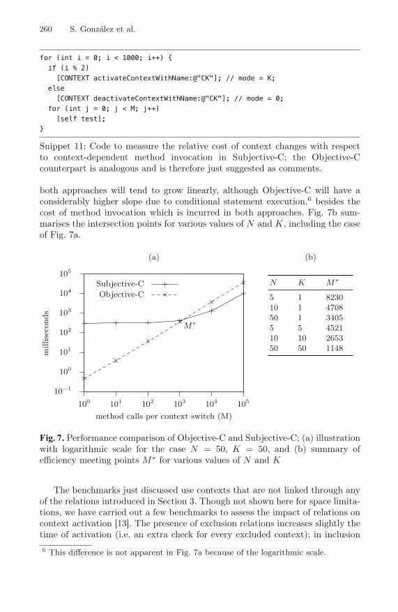
for (int i = 0; i < 1000; i++) {if (i % 2)[CONTEXT activateContextWithName:@"CK"]; // mode = K;
else[CONTEXT deactivateContextWithName:@"CK"]; // mode = 0;
for (int j = 0; j < M; j++)[self test];
}
Snippet 11: Code to measure the relative cost of context changes with respectto context-dependent method invocation in Subjective-C; the Objective-Ccounterpart is analogous and is therefore just suggested as comments.
both approaches will tend to grow linearly, although Objective-C will have aconsiderably higher slope due to conditional statement execution,6 besides thecost of method invocation which is incurred in both approaches. Fig. 7b sum-marises the intersection points for various values of N and K, including the caseof Fig. 7a.
(a)
10−1
100
101
102
103
104
105
100 101 102 103 104 105
mill
isec
onds
method calls per context switch (M)
M∗
Subjective-CObjective-C
(b)
N K M∗
5 1 823010 1 470850 1 34055 5 452110 10 265350 50 1148
Fig. 7: Performance comparison of Objective-C and Subjective-C; (a) illustrationwith logarithmic scale for the case N = 50, K = 50, and (b) summary ofefficiency meeting points M∗ for various values of N and K
The benchmarks just discussed use contexts that are not linked through anyof the relations introduced in Section 3. Though not shown here for space limita-tions, we have carried out a few benchmarks to assess the impact of relations oncontext activation [13]. The presence of exclusion relations increases slightly thetime of activation (i.e. an extra check for every excluded context); in inclusion6 This difference is not apparent in Fig. 7a because of the logarithmic scale.
260 S. Gonzalez et al.

relations, the (de)activation must be not only accepted but also propagated onthe chain of included contexts. Processing inclusion relations is about 4 timesmore costly than processing exclusion relations.
In another benchmark we assessed the cost of activation according to thenumber of methods associated to the switched context. As can be expected, theactivation time increases linearly with the number of methods (e.g. if a contexthas twice as many methods, it takes twice as much time to switch).
Yet in one more benchmark we evaluated the activation time according tonumber of contexts that specialise a given method. In our implementation, theexecution time grows linearly with the number of contexts that implement thesame method, because finding the most specific method involves a linear searchin a list of available methods.7
The efficiency of Subjective-C depends highly on its usage. Most benefits areobtained for contexts that are switched infrequently with respect to the rate ofusage of affected methods. Fortunately, this is the case for most common scenar-ios, because context changes are usually linked to physical phenomena such asorientation changes, temperature changes, battery charge changes, network con-nections, and so forth. In particular, in each of the three case studies described inSection 5, the Subjective-C implementation did not give rise to apparent perfor-mance penalties. This being said, we can think of a few kinds of contexts whichcould be switched very rapidly, for instance software memory transactions imple-mented as contexts [7], used in tight loops. For these cases the penalty incurredby Subjective-C could become detrimental to overall performance. However, formost practical cases we can conclude that COP abstractions do not incur aperformance penalty that would bar them from mobile platform programming.
7 Limitations and Future Work
Even though Subjective-C is usable for application development on mobile de-vices as suggested in Section 5, it still has rough edges we need to iron out. Thissection describes the most salient ones, starting with the more technical andgoing over to the more conceptual.
Super-Context Translation. A caveat of the implementation presented inSection 4.3 is the impossibility to retrieve the return value from a superContextmessage. Our current solution consists in having a different syntax when thereturn value is needed, which complements the definition of the superContextconstruct given in Section 2.4:
[superContext selector] => variable;[superContext keyword: argument ...] => variable;
This syntax is translated to a variant of the SUPERCONTEXT macro which expandsthe message as variable = _message instead of just _message.7 We have invested no effort yet in improving this straightforward implementation.
Subjective-C 261

The additional syntax shown here is due to a particularity of our currentimplementation, but we see no fundamental reason why it could not be avoidedin a more sophisticated version of the compiler.
Context Scope and Concurrency. Context activation in Subjective-C isglobal. All threads share the same active context and see the effects of con-text switching performed by other threads. This can give rise to race conditionsand behavioural inconsistencies if concurrent context switches occur at inappro-priate execution points [9]. However, note that this issue does not stem from aconceptual error. As discussed in Section 2.1, any computing device is embeddedin a physical and logical execution environment, which all applications runningon the device share. For instance, it is natural that all applications become awareof a LowBattery condition, or a reorientation of the device to Landscape position.Rather than avoiding the problem of shared contexts altogether by limiting thescope of context effects to individual threads, our open research challenge andline of future work consists in detecting the execution points at which sharedcontext changes are safe to perform, whether automatically or with some sort ofassistance such as source code annotations.
Nevertheless, having made a case for global contexts, we do believe thatadding support for local contexts, representing the running conditions of par-ticular threads, would be a useful addition to Subjective-C. For instance, onethread could run in Debug or Tracing mode simultaneously with other threadsrunning in default mode.
Behaviour Disambiguation. Whenever multiple methods are applicable fora given message and active context configuration, the context manager shouldbe able to deterministically define which of the methods is to be invoked. Forexample, suppose there are two versions of UILabel’s drawTextInRect: method,respectively specialised on the Landscape and LowBattery contexts. If both con-texts are active at any given time, it is unclear which of the two versions ofdrawTextInRect: should be applied first.
Currently, the choice is based on a priority assigned to every method. De-fault methods have always less priority than context-dependent methods. Fortwo context-dependent methods, the priority is given by the order in which thecompiler comes across the method definitions.8 Hence, the later a method isfound, the higher its priority. Clearly this ad hoc mechanism to automaticallydetermine priorities is insufficient. A better solution is to define a version of theambiguous method specialised on the set of conflicting contexts (in the exam-ple, Landscape and LowBattery), and resolve the ambiguity manually in thatspecific method implementation. This solution cannot be used for every possiblecombination as this would result in a combinatorial explosion. A line of researchis to help predicting which ambiguities arise in practice by analysing contextrelations, and provide declarative rules to resolve remaining ambiguities basedon domain-specific criteria.
8 Note that Objective-C open classes can be defined across multiple files.
262 S. Gonzalez et al.

8 Related Work
COP-like ideas for object-oriented systems can be traced back as far as 1996.The Us language, an extension of the Self language with subjective object be-haviour [17], inspired our work since the early stages. In Us, subjectivity is ob-tained by allowing multiple perspectives from which different object behaviourmight be observed. These perspectives are reified as layer objects, and hence,Us layers are akin to Subjective-C contexts.
The contemporary notion of COP has been realised through a few imple-mentations, in particular ContextL [4] which extends CLOS [2], Ambience [9]which is based on AmOS [8], and further extensions of Smalltalk [10], Python[14] and Ruby,9 among others. Most existing approaches, with the exception ofAmbience, seem to be conceptual descendants of ContextL, and therefore sharesimilar characteristics. None of these COP languages is similar to Subjective-Cin that they affect method dispatch semantics to achieve dynamic behaviourselection, whereas Subjective-C uses method predispatching, introduced inSection 4.2.
Subjective-C is inspired on our previous work with Ambience. In particular,both languages use the notion of contexts as objects representing particularrun-time situations, described in Section 2.2. Further, contexts in Ambience arealso global and shared by all running threads, an issue discussed in Section 7.Whereas in Ambience it would not be difficult to adapt the underlying AmOSobject model to support thread-local contexts, in Subjective-C we do not controlthe underlying object system inherited from Objective-C.
An issue barely tackled by existing COP approaches is the high-level mod-elling of contexts and their conditions of activation. Subjective-C makes a stepforward in this direction by introducing different types of relations between con-texts, explained in Section 3. This system of relations bears a strong resemblanceto some of the models found in Software Product Line Engineering (SPLE). Un-fortunately, thus far SPLE has focused mostly on systems with variability instatic contexts [15]. Variability models such as Feature Diagrams (FDs) [11]and their extensions have not been geared towards capturing the dynamism ofcontext-dependent behavior. More recent work on variability models acknowl-edges the concept of dynamic variability in SPLE [3,5,12].
Also related to COP in general, and Subjective-C in particular, is the familyof dynamic Aspect-Oriented Programming approaches. PROSE [16] for instanceis a Java-based system using dynamic Aspect-Oriented Programming (AOP)for run-time adaptability. Since dynamic aspects can be woven and unwovenaccording to context, dynamic AOP can be a suitable option to obtain dynamicbehaviour adaptation to context. Dynamic AOP buys flexibility (for instance,the ability to express join points that capture only certain invocations of a givenmethod, instead of every invocation) at the expense of more conceptual andtechnical complexity (e.g. additional join point language and abstractions foraspect definition).
9 http://contextr.rubyforge.org
Subjective-C 263
9 Conclusions
The field of Context-Oriented Programming (COP) was born in response to alack of adequate programming abstractions to develop adaptable applicationsthat are sensible to their changing execution conditions. Observing that no ex-isting COP language allowed us to experiment with context-oriented mobileapplication programming, we set out to develop an extension of one of the mostwidely used languages for mobile devices, namely Objective-C. The result is theSubjective-C language,which furnishes dedicated language abstractions to dealwith context-specific method definitions and thus permits run-time behaviouraladaptation to context. Subjective-C objects are less “objective” than those ofObjective-C in that their expressed behaviour does not depend entirely on themessages they receive, but also on the current execution context.
Subjective-C goes beyond existing COP approaches by providing an explicitmeans to express complex context interrelations. The different relations havea corresponding graphical depiction and textual representation, to ease theirdescription and communication among developers and domain experts. Althoughwe cannot guarantee that the set of supported relation types is complete enoughto express all relevant context settings, we have found it to be sufficient inpractice for now.
Subjective-C introduces an original implementation technique that tradescontext switching efficiency for method execution efficiency. Our experience withthe validation cases shows that this technique results in no noticeable efficiencypenalties, despite the relatively resource-constrained host platforms on whichthese applications run. Even more, under some circumstances efficiency is im-proved as compared to using plain Objective-C. From the same experience wehave observed that Subjective-C seems to achieve its ultimate software engineer-ing goals, which are improved modularisation, increased readability, reusability,maintainability and extensibility of context-aware software.
Acknowledgements
This work has been supported by the ICT Impulse Programme of the Institutefor the encouragement of Scientific Research and Innovation of Brussels, and bythe Interuniversity Attraction Poles Programme, Belgian State, Belgian SciencePolicy. We thank the anonymous reviewers for their comments on an earlierversion of this paper.
References
1. Appeltauer, M., Hirschfeld, R., Haupt, M., Masuhara, H.: ContextJ: Context-oriented programming for Java. Computer Software of The Japan Society for Soft-ware Science and Technology (June 2010)
2. Bobrow, D., DeMichiel, L., Gabriel, R., Keene, S., Kiczales, G., Moon, D.: CommonLisp Object System specification. Lisp and Symbolic Computation 1(3/4), 245–394(1989)
264 S. Gonzalez et al.

3. Cetina, C., Haugen, O., Zhang, X., Fleurey, F., Pelechano, V.: Strategies for vari-ability transformation at run time. In: Proceedings of the International SoftwareProduct Line Conference, pp. 61–70. Carnegie Mellon University, Pittsburgh (2009)
4. Costanza, P., Hirschfeld, R.: Language constructs for context-oriented program-ming: an overview of ContextL. In: Proceedings of the Dynamic Languages Sym-posium, pp. 1–10. ACM Press, New York (2005); co-located with OOPSLA 2005
5. Desmet, B., Vallejos, J., Costanza, P., Kantarcioglu, M., D’Hondt, T.: Context-oriented domain analysis. In: Kokinov, B., Richardson, D.C., Roth-Berghofer, T.R.,Vieu, L. (eds.) CONTEXT 2007. LNCS (LNAI), vol. 4635, pp. 178–191. Springer,Heidelberg (2007)
6. Garlan, D., Cheng, S.W., Huang, A.C., Schmerl, B., Steenkiste, P.: Rainbow:Architecture-based self-adaptation with reusable infrastructure. Computer 37(10),46–54 (2004)
7. Gonzalez, S., Denker, M., Mens, K.: Transactional contexts: Harnessing the powerof context-oriented reflection. In: International Workshop on Context-Oriented Pro-gramming, July 7, pp. 1–6. ACM Press, New York (2009)
8. Gonzalez, S., Mens, K., Cadiz, A.: Context-Oriented Programming with the Am-bient Object System. Journal of Universal Computer Science 14(20), 3307–3332(2008)
9. Gonzalez, S., Mens, K., Heymans, P.: Highly dynamic behaviour adaptabilitythrough prototypes with subjective multimethods. In: Proceedings of the DynamicLanguages Symposium, pp. 77–88. ACM Press, New York (2007)
10. Hirschfeld, R., Costanza, P., Haupt, M.: An introduction to context-oriented pro-gramming with contextS. In: Lammel, R., Visser, J., Saraiva, J. (eds.) GTTSE2007. LNCS, vol. 5235, pp. 396–407. Springer, Heidelberg (2008)
11. Kang, K.C., Cohen, S.G., Hess, J.A., Novak, W.E., Peterson, A.S.: Feature-orienteddomain analysis (foda) feasibility study. Tech. Rep. CMU/SEI-90-TR-21, Carnegie-Mellon University Software Engineering Institute (November 1990)
12. Lee, J., Kang, K.C.: A feature-oriented approach to developing dynamically recon-figurable products in product line engineering. In: Proceedings of the InternationalSoftware Product Line Conference, pp. 131–140. IEEE Computer Society Press,Los Alamitos (2006)
13. Libbrecht, J.C., Goffaux, J.: Subjective-C: Enabling Context-Aware Programmingon iPhones. Master’s thesis, Ecole Polytechnique de Louvain, UCLouvain (June2010)
14. von Lowis, M., Denker, M., Nierstrasz, O.: Context-oriented programming: Beyondlayers. In: Proceedings of the 2007 International Conference on Dynamic languages,pp. 143–156. ACM Press, New York (2007)
15. Pohl, K., Bockle, G., van der Linden, F.: Software Product Line Engineering: Foun-dations, Principles and Techniques. Springer, Heidelberg (2005)
16. Popovici, A., Gross, T., Alonso, G.: Dynamic weaving for aspect-oriented program-ming. In: Proceedings of the International Conference on Aspect-Oriented SoftwareDevelopment, pp. 141–147. ACM Press, New York (2002)
17. Smith, R.B., Ungar, D.: A simple and unifying approach to subjective objects.Theory and Practice of Object Systems 2(3), 161–178 (1996)
18. Vallejos, J., Gonzalez, S., Costanza, P., De Meuter, W., D’Hondt, T., Mens, K.:Predicated generic functions. In: Baudry, B., Wohlstadter, E. (eds.) SC 2010.LNCS, vol. 6144, pp. 66–81. Springer, Heidelberg (2010)
Subjective-C 265

B. Malloy, S. Staab, and M. van den Brand (Eds.): SLE 2010, LNCS 6563, pp. 266–275, 2011. © Springer-Verlag Berlin Heidelberg 2011
The Level-Agnostic Modeling Language
Colin Atkinson, Bastian Kennel, and Björn Goß
Chair of Software Technology, University Mannheim A5, 6 B 68131 Mannheim, Germany
{Colin.Atkinson,Bastian.Kennel, Bjoern.Goss}@informatik.uni-mannheim.de
Abstract. As an alternative modeling infrastructure and paradigm, multi-level modeling addresses many of the conceptual weaknesses found in the four level modeling infrastructure that underpins traditional modeling approaches like UML and EMF. It does this by explicitly distinguishing between linguistic and ontological forms of classification and by allowing the influence of classifiers to extend over more than one level of instantiation. Multi-level modeling is consequently starting to receive attention from a growing number of research groups. However, there has never been a concrete definition of a language de-signed from the ground-up for the specific purpose of representing multi-level models. Some authors have informally defined the “look and feel” of such a language, but to date there has been no systematic or fully elaborated definition of its concrete syntax. In this paper we address this problem by introducing the key elements of a language, known as the Level-Agnostic Modeling Language (LML) designed to support multi-level modeling.
Keywords: Multi-Level Modeling, Modeling Language.
1 Introduction
Since it kick started the modern era of model driven development in the early 90s, the concrete syntax of the structural modeling features of the UML has changed very lit-tle. Almost all the major enhancements in the UML have focused on its abstract syn-tax and infrastructure [1]. Arguably, however, the original success of the UML was due to its concrete syntax rather than its abstract syntax as the former has been adopted in many other information modeling approaches, such as ontology and data modeling [9]. Today, discussions about the concrete syntax of languages usually take place in the context of domain specific modeling languages [3]. Indeed, domain spe-cific languages are increasingly seen as one of the key enabling technologies in soft-ware engineering. While the importance of domain specific languages is beyond doubt, universal languages that capture information in a domain independent way still have an important role to play. They not only provide domain-spanning representa-tions of information, they can tie different domain specific languages together within a single framework.
Existing universal languages such as the UML are not set up to fulfill this role. The UML's infrastructure not only has numerous conceptual weaknesses [5], it does not

The Level-Agnostic Modeling Language 267
satisfactorily accommodate the newer modeling paradigms that have become popular in recent years, such as ontology engineering [2]. In this paper we present a proposal for a new universal modeling language that addresses these weaknesses. Known as the Level-agnostic Modeling language, or LML for short, the language is intended to provide support for multi-level modeling, seen by a growing number of researchers as the best conceptual foundation for class/object oriented modeling [6], [7], [8]. It is also intended to accommodate other major knowledge/information modeling ap-proaches and to dovetail seamlessly with domain specific languages. Since the core ideas behind multi-level modeling have been described in a number of other publica-tions, in this paper we focus on the concrete syntax of the LML and only provide enough information about the semantics and abstract syntax to make it understand-able. The language is essentially a consolidation and extension of the notation informally employed by Atkinson and Kühne in their various papers on multi-level modeling [6], [11], [12]. Some of the concrete goals the LML was designed to fulfill are as follows:
To be UML-like. Despite its weaknesses, the UML's core structural modeling fea-tures, and the concrete syntax used to represent them, have been a phenomenal suc-cess and have become the de facto standard for the graphical representation of models in software engineering. To the greatest extent possible the LML was de-signed to adhere to the concrete syntax and modeling conventions of the UML.
To be level agnostic. The language was designed to support multi-level modeling based on the orthogonal classification architecture described by Atkinson, Kühne and others [6], [7], [12]. The core requirement arising from this goal is the uniform (i.e. level agnostic) representation of model elements across all ontological model-ing levels (models) in a multi-level model (ontology).
To accommodate all mainstream modeling paradigms. Although UML is the most widely used modeling language in software engineering, in other communi-ties other languages are more prominent. For example, in the semantic web and ar-tificial intelligence communities ontology languages like OWL [9] are widely used, while in the database design community Entity Relationship modeling lan-guages such as those proposed by Chen [13] are still important. A key goal of the LML therefore is to support as many of these modeling paradigms as possible, consistent with the overall goal of being UML-oriented.
To provide simple support for reasoning services. The lack of reasoning ser-vices of the kind offered by languages such as OWL is one of the main perceived weaknesses of UML. However, there are many forms and varieties of reasoning and checking services provided by different tools, often with non-obvious seman-tics. One goal of the LML is therefore to provide a foundation for a unified and simplified set of reasoning and model checking services.
Unfortunately, due to space restrictions it is only possible to provide a general over-view of LML's features, and it is not possible to discuss LML's support for reasoning services in any detail. In the next section we provide a brief overview of multi-level modeling and the infrastructure that underpins the LML. In section 3 we then present the main features of the language in the context of a small case study motivated by the movie Antz. In section 4 we discuss logical relationships, which are one of the

268 C. Atkinson, B. Kennel, and B. Goß
foundations for the reasoning services built on the LML, before concluding with some final remarks in section 5.
2 Orthogonal Classification Architecture
As illustrated in Fig. 1, the essential difference between the orthogonal classification architecture and the traditional four level modeling architecture of the OMG and EMF is that there are two classification dimensions rather than one. In the linguistic dimen-sion, each element in the domain modeling level (L1) is classified according to its linguistic type in the L0 level above. Thus, elements such as AntType, Ant, Queen and the relationships between them are defined as instances of model elements in the L0 level according to their linguistic role or form. In the ontological dimension, each element in an ontological level (e.g. O1, O2, ..) is classified according to its ontologi-cal type in the ontological level above (i.e. to the left in Fig. 1). Thus Bala is an onto-logical instance of Queen, which in turn is an ontological instance of AntType. The elements in the top level in each dimension (with the label 0) do not have a classifier. The bottom level in Fig. 1 is not part of the modeling infrastructure, per se, but con-tains the entities that are represented by the model element in L1. Like the bottom level of the OMG and EMF modeling infrastructures, therefore, it can be regarded as representing the “real world”.
Fig. 1. Multi-Level Modeling Example
In principle, it is possible to have an arbitrary number of linguistic levels, but in practice the arrangement shown in Fig. 1 is sufficient. In our orthogonal classification architecture there are only two linguistic levels and only one of these, L1, is divided into ontological levels. The top level linguistic model therefore defines the underlying representation format for all domain-oriented and user-defined model content in the L1 level, and spans all the ontological levels in L1. For this reason we refer to it as the Pan-Level Model or PLM for short. In effect, it plays the same role as the MOF and Ecore in the OMG and EMF modeling infrastructures, but its relationship to user models respects the tenet of strict meta modeling [5].
The Pan Level Model (PLM) defines the abstract syntax of the language that we in-troduce in the ensuing sections [10]. The LML therefore essentially defines a concrete

The Level-Agnostic Modeling Language 269
syntax for the PLM. To simplify discussions about content organized in the way shown in Fig. 1 we use the terms “ontology” and “model” in a specific way. We call all the modeling content in the L1 level, across all ontological levels, an “ontology”, while we call the modeling content within a single ontological level a “model”. This is consistent with common use of the terms since models in the UML are usually type models [14] and ontologies often define the relationships between instances and types (i.e. the relationship between two ontological levels or models).
There are two basic kinds of elements in an LML ontology: InstantiatableElements and LogicalElements, each of which has a name attribute and an owner attribute. In-stantiatableElements are the core modeling elements that fulfill the role of classes, objects, associations, links and features in traditional modeling languages such as the UML, OWL or ER languages. The main difference is that they fulfill these roles in a level-agnostic way. LogicalElements on the other hand represent classification, gener-alization and set theoretic relationships between InstanstiatableElements. Instantiat-ableElements come in two basic forms, Clabjects, which represent classes, objects, associations and links, and Features that play a similar role to features in the UML – that is, attributes, slots and methods. Field is the subclass of Feature that plays the role of attributes and/or slots, while Method is the subclass of Feature that plays the role of methods. Clabjects, in general, can simultaneously be classes and objects (hence the name – a derivative of “class” and “object”). In other words they represent model elements that have an instance facet and a type facet at the same time. There are two kinds of Clabjects, DomainEntities and DomainConnections. DomainEntities are Clabjects that represent core domain concepts, while DomainConnections, as there name implies, represent relationship between Clabjects. They play the role of associations and links, but in a way that resembles association classes with their own attributes and slots.
3 Clabjects
The concrete representation of clabjects in LML is based on the notational conventions developed by Atkinson and Kühne [11] which in turn are based on the UML. Fig. 2 shows an example multi-level model (i.e. ontology) rendered using the LML concrete syntax. Inspired by the film Antz, this contains three ontological levels (i.e. models) organized vertically rather than horizontally as in Fig. 1.
In its full form a clabject has three compartments: a header compartment, a field compartments and a method compartment. The header is the only mandatory com-partment and must contain an identifier for the clabject, shown in bold font. This can be followed, optionally, by a superscript indicating the clabject's potency and a sub-script indicating the ontological level (or model) that it occupies. Like a multiplicity constraint, a potency is a non-negative integer value or “*” standing for “unlimited” (i.e. no constraint). Thus the clabject FlyingAnt, in Fig. 2 has potency 1 and level 1, while clabject Z has potency 0 and level 2. The field and method compartments are both optional. They intentionally resemble the attribute and slot compartments in UML classes and objects. However, the key difference once again is that the notation for fields is level agnostic. This allows them to represent UML-like attributes, slots and a mixture of both, depending on their potency.

270 C. Atkinson, B. Kennel, and B. Goß
Fig. 2. Antz domain example in LML concrete syntax

The Level-Agnostic Modeling Language 271
Potencies on fields follow the same rules as potencies on domain entities. The only constraint is that a field cannot have a higher potency than the clabject that owns it. In general, the representation of a field has three parts: a name, which is mandatory, a type and a value. A traditional UML slot corresponds to a potency 0 field with a value, whereas a traditional UML attribute corresponds to a potency 1 field without a value.
When a value is assigned to a field with a potency greater than 0, the value represents the default value for corresponding fields of the clabject's instances. In Fig. 2, FlyingAnt has a potency 0 field, hasWings, of type Boolean with the value True.
Methods are represented in the same way as operations in the UML using signature expressions that include the name, the input parameters and the return value if there is one. The only difference is that methods in LML have a potency associated with them. As with fields, the potency of a method cannot be higher than the potency of its owning clabject.
3.1 Proximity Indication
The UML provides various notational enhancements in the header compartment of classes and objects to show their location within the instantiation, inheritance and con-tainment hierarchies. More specifically, the “:” symbol can be used to to express the fact that an object is an instance of a class and the “::” notation can be used to show that a model element belongs to, or is contained in, another model element. However, these notations are rather ad hoc and cannot be used in a level agnostic way. For exam-ple, to show that a class is an instance of another class at a higher meta-level, a stereo-type has to be “attached” to the class using the guillemot notation. Alternatively, the powertype concept can also be used to indicate that a class X is an instance of another class Y, but only if it is one of numerous subclasses of another class, Z. In contrast to the UML, the LML provides a fully level-agnostic way of representing a clabject's location in the instantiation, inheritance and containment hierarchies.
Classification (Instantiation) Hierarchy. The basic notation for representing a clab-ject's location in the instantiation hierarchy in the LML is the same as that used in the UML for objects. In Fig. 2, the header of the Worker clabject, “Worker:AntType”, indicates that Worker is an instance of AntType. Of course this notation can also be applied over multiple ontological levels as shown in the header of Azteca (“Azteca:Worker:AntType”). It is also possible to use the “::” notation to omit one one or more clabjects in the instantiation hierarchy. For example, if it is only of rele-vance that Azteca is an instance of AntType, Azteca's header can be reduced to “Azteca::AntType”.
Generalization (Inheritance) Hierarchy. The UML provides no way of showing the ancestry of a class within its header compartment. In LML this can be done using the “<” symbol on the left hand side of a clabject's name to represent subtypeOf relation-ships. This is intended to resemble the white triangle at the supertype end of a gener-alization in the UML. As with the “::” notation, two consecutive “<” characters can be used to indicate that one or more clabjects of the inheritance hierarchy are not identi-fied. Thus, the header of Soldier in Fig. 2 shows that it is a subclass of Worker and Ant, but omits the fact that it is also a subclass of FemaleAnt. Of course, in Fig. 2 this

272 C. Atkinson, B. Kennel, and B. Goß
information is redundant in the header of Soldier because the inheritance hierarchy is shown explicitly using generalization relationships.
Ownership (Containment) Hierarchy. Ownership is the basis for defining namespaces. Basically, an element is a namespace for everything that it owns - that is, anything that identifies it as its owner through its owner attribute. The relationship between a clabject and its Fields is also ownership. Fields have the clabject they be-long to as their owner. Ownership information can be included in the identifier of a clabject, like the Ant clabject in Fig. 2. In LML this is shown using the “.” symbol rather than the “::” symbol as in the UML. This is consistent with the notation used in programming languages such as Java. Thus, the header of Ant in Fig. 2, “”Antz.O1.Ant”, shows that Ant is contained in the model O1 which in turn is con-tained in the ontology Antz.
3.2 Attribute Value Specifications
In traditional modeling environments, model elements only derive their attributes from one type, and in UML like languages these are shown in the compartment below the header. In a multi-level modeling environment, all model elements except those at the top ontological level (i.e. model) have two types, a linguistic one and an ontologi-cal one. The attributes of the ontological types are shown in the field compartment in the traditional way. The linguistic attributes, in contrast, are shown elsewhere in one of two different ways. The first way uses special notations or conventions for differ-ent attributes, such as the subscript and superscript notations for level and potency. The second way is to add explicit “attribute specifications” under the name of a clab-ject, similar to tagged value specifications in the UML. The general form of an attrib-ute value specification, is the following
{attributeName = value, attributeName = value, ...}
For boolean attributes the UML convention applies. If a boolean attribute is true it is only necessary to include its name in the list. However, if this convention is used then all true boolean attributes of the clabject must be shown as well. This is because all boolean attributes that are not shown are assumed to be false. In Fig. 2 the Ant clab-ject has an attribute value specification indicating the value of it attributes.
3.3 Domain Connections
As mentioned in section 2, there are two distinct kinds of clabjects – domain entities and domain connections. The former play a role similar to classes/objects in the UML and the latter play a role similar to associations/links. As shown in Fig. 2 they are distinguished visually by different symbols - rectangles in the case of domain enti-ties and flattened hexagons in the case of domain connections. This is intended to resemble the diamond symbol that is used to represent connections in Entity Relation-ship diagrams [13]. ERA diagrams can therefore easily be represented in LML. We use flattened hexagons rather than diamonds because they are ergonomically more compact.
The other major difference is that domain connections are responsible for “carry-ing” the lines that are used in the representation of connections. The problem with

The Level-Agnostic Modeling Language 273
using a symbol like a hexagon to represent a domain connection is that this breaks the fundamental visualization metaphor of the UML in which relationships are mapped to edges rather than nodes. To address this problem and accommodate both the UML and ERA visualization metaphors at the same time, LML allows a domain connection to be represented in an imploded form by a “visually insignificant” dot as well as in the full exploded form as a flattened hexagon [15]. In the former case, the domain connection is still conceptually represented as a node, but the overall visual effect is that of an edge as in the UML. In Fig. 2, the domain connection mate is shown in this dotted form. This shows that the multiplicity constraints, role names and navigability values owned by the domain connection can be shown at the end of the appropriate lines using the standard UML conventions. In general, it is possible to present all the information that can appear in the header of the expanded form of a domain connec-tion next to the dot. This includes the name and an attribute value specification. How-ever, the fields and methods of a domain connection can only be shown in the ex-panded form, as indicated by the descends connections in Fig. 2.
4 Logical Elements
Logical relationships capture set theoretic relationships between clabjects and come in three basic forms – Generalization, Instantiation, and SetRelationship. The first kind captures subtyping/supertyping relationships between clabjects, the second kind cap-tures classification relationships between clabjects and the third kind captures other general set theoretic relationships between clabjects. Since they are relationships, the same basic representation options used for Domain-Connections is also supported for LogicalElements – namely, they can be rendered in an exploded form and in an imploded form as a “dot”. The expanded form uses a slightly different symbol to DomainConnections – namely, a “rectangle” with rounded sides at the top and bottom. Another minor difference is that for logical rela-tionships the name is optional in the expanded form.
Generalization. Generalization relationships show the basic subtype/supertype re-lationships in set-based models. In Fig. 2, the connection-line between Ant and Thing using the white triangular arrow (which is similar to the UML representation of generalizations) indicates that Ant is a subtype of Thing in the imploded repre-sentation. The generalization, maleFly, on the other hand shows generalization in an exploded form. It indicates that FlyingAnt and FemaleAnt are both subtypes of Ant. Besides the generalization's name the generalization symbol contains an at-tribute value specification indicating that maleFly is complete.
Instantiation. Instantiation relationships show that one clabject is an instance of another clabject. As such they are the only kind of relationships that are allowed to cross an ontological level boundary (in fact they have to) to connect two clabjects at different levels. As the instantiation between Bala and Queen in Fig. 2 shows, Instantiation relationships are represented in a similar way to the UML using an open-headed, dashed arrow going from the instance to the type. They can also be represented in an imploded or exploded form.
SetRelationship. Set relationships specificity some other kind of set theoretic rela-tionship between clabject. Typical examples are complements, inverseOf and

274 C. Atkinson, B. Kennel, and B. Goß
equals. The equals relationship between FlyingAnt and FertileAnt in Fig. 2 indi-cates that they essentially represent the same set, since every fertile ant can fly and only fertile ants can fly. As usual the name of the relationship is shown inside the shape. Set relationships do not normally have attribute value specifications.
5 Conclusion
In this paper we have presented a language, LML, designed to support multi-level modeling using the orthogonal classification architecture, with a focus on its concrete syntax. As mentioned in the introduction this work builds on the informal notation developed by Atkinson and Kühne in a series of papers. As well as supporting multi-level modeling the language has also been designed to exhibit several other important characteristics. However, for space reasons it is not possible to fully explain them all in a paper of this size.
First, to the greatest extent possible, LML was designed to support and be consis-tent with the notations and conventions popularized by the UML. As is hopefully evi-dent from the discussion, LML can easily be made to have the look and feel of tradi-tional UML. Like the UML, the LML concrete syntax is intended to be renderable in black and white and to be readily drawable by hand where necessary. There are lots of ways in which colour could enhance the information shown in LML diagrams, but this is left to individual tools and modelers.
Second, LML is also designed to support the look and feel of other important mod-eling paradigms as well. In particular it can support the entity relationship modeling approach pioneered by Chen for data modeling and contains all the features needed to represent OWL ontologies. Because it supports all ontological levels in a uniform and relatively rich way, the LML provides a natural representation of both instance and type knowledge. OWL, in contrast, only directly supports the latter.
Third, the language has built-in support for depicting which information in a model has been explicitly expressed by a human modeler and which has been computed by a reasoning or transformation engine. This allows the LML to support simpler, more understandable reasoning services. For example the traditional “subsumption” service offered by ontology engineering tools such as Protegé [16] essentially computes new generalization and classification relationships based on the properties of the classes and objects in the ontology. With LML, these could be offered in a more understand-able way through services such as “add all generalizations” or “add all instantiation relationships”. This not only breaks down the service into its constituent parts which can be invoked independently, it also allows them to be fine tuned into more useful services.
Finally, the language includes various kinds of elision symbols which can show when expressed information is not shown in a particular view of a model. In other words, it can be used to show that the underlying model or knowledge base has fur-ther expressed information that is not shown in the current diagram. This is important in clarifying whether a diagram, and queries direct to it, should be interpreted in an “open world” or a “close world” way.
Although the focus of modeling language research has turned from universal mod-eling languages like the UML to DSLs we believe the evolution of universal modeling

The Level-Agnostic Modeling Language 275
languages is far from over. We hope the ideas presented in this paper will contribute towards this evolution and will help lead towards a better synergy of DSL and univer-sal modeling languages. We also hope it will pave the way for a unification of soft-ware modeling (i.e. UML-oriented), knowledge representation (i.e. OWL-oriented) and information modeling (i.e. ER-oriented) technologies.
References
1. OMG UML 2.1.2 Infrastructure Specification, Object Management Group (OMG), Tech. Rep. (2007)
2. Gasevic, D., Djuric, D., Devedzic, V., Damjanovi, V.: Converting UML to OWL ontolo-gies. In: Proceedings of the 13th International World Wide Web, New York, NY (2004)
3. Tolvanen, J.: MetaEdit+: Domain-Specific Modeling for Full Code Generation Demon-strated. In: Proc. 19th Ann. ACM SIGPLAN Conf. Object-Oriented Programming Sys-tems, Languages, and Applications (2004)
4. GreenField, J., Short, K., Cook, S., Kent, S., Crupi, J.: Software Factories: Assembling Applications with Patterns, Models, Frameworks, and Tools. John Wiley and Sons, Chichester (2004)
5. Atkinson, C., Kühne, T.: Rearchitecting the UML Infrastructure. ACM Journal Transac-tions on Modeling and Computer Simulation 12(4) (2002)
6. Atkinson, C., Kühne, T.: Model-Driven Development: A Metamodeling Foundation. IEEE Software (2003)
7. Asikainen, T., Männistö, T.: Nivel:a metamodelling language with a formal semantics. Software and Systems Modeling 8(4), 521–549 (2009)
8. Aschauer, T., Dauenhauer, G., Pree, W.: Multi-level Modeling for Industrial Automation Systems. In: Software Engineering and Advanced Applications, Euromicro Conference, pp. 490–496 (2009)
9. OWL (2004), http://www.w3.org/2004/OWL 10. Atkinson, C., Gutheil, M., Kennel, B.: A Flexible Infrastructure for Multi-Level Language
Engineering. IEEE Transactions on Software Engineering 35(6) (2009) 11. Atkinson, C., Kühne, T.: The essence of multilevel metamodeling. In: Gogolla, M.,
Kobryn, C. (eds.) UML 2001. LNCS, vol. 2185, pp. 19–33. Springer, Heidelberg (2001) 12. Atkinson, C., Kühne, T.: Reducing accidental complexity in domain models. In: Software
and Systems Modeling (2007) 13. Chen, P.: The Entity-Relationship Model: Toward a Unified View of Data. ACM Transac-
tions on Database Systems 1, 9–36 (1976) 14. Kühne, T.: Matters of (Meta-)Modeling. Journal on Software and Systems Modeling 5(4),
369–385 (2006) 15. Gutheil, M., Kennel, B., Atkinson, C.: A Systematic Approach to Connectors in a Multi-
Level Modeling Environment. In: Proc. 11th Int’l Conf. Model Driven Eng. Languages and Systems (2008)
16. Protege Tool (2008), http://protege.stanford.edu

Debugging in Domain-Specific Modelling
Raphael Mannadiar1 and Hans Vangheluwe1,2
Modelling, Simulation and Design Lab1 McGill University
3480 University StreetMontreal, Quebec, Canada
2 University of AntwerpMiddelheimlaan 1
2020 Antwerpen, Belgium
Abstract. An important obstacle to the wide-spread adoption of model-driven development approaches in industry is the lack of proper debug-ging facilities. Software debugging support is provided by a combinationof language and Integrated Development Environment (IDE) featureswhich enable the monitoring and altering of a running program’s state.In Domain-Specific Modelling (DSM), debugging activities have a widerscope: designers debug model transformations (MTs) and synthesizedartifacts, while domain-specific modellers debug their models, unawareof generated artifacts. This work surveys the state-of-the-art of debug-ging in the context of DSM and proposes a mapping between debuggingconcepts (e.g., breakpoints, assertions) in the software and DSM realms.
1 Introduction
DSM allows domain experts to play active roles in (software) development ef-forts. It provides them with means to manipulate constructs they are familiarwith and to automate the error-prone and time-consuming conceptual mappingbetween the (often very distant) problem and solution domains. Empirical evi-dence suggests increases in productivity of up to one order of magnitude whenusing DSM and automatic artifact synthesis as opposed to traditional code-driven development approaches [9,5].
MTs1 are used to specify the semantics of Domain-Specific Languages (DSLs)by defining interpreters or by mapping onto formalisms whose semantics is wellunderstood such as Petri Nets, Statecharts or code. In this work, we focus onrule-based approaches, where MTs are composed of rules, each parameterized bya left-hand side (LHS) and right-hand side (RHS) pattern, an optional negativeapplication condition (NAC) pattern, condition code, and action code. The LHSand NAC patterns respectively describe what sub-graphs should and shouldnot be present in the source model for the rule to be applicable while the RHSpattern describes how the LHS pattern should be transformed by its application.
1 See [2] for a detailed feature-based classification of existing MT techniques.
B. Malloy, S. Staab, and M. van den Brand (Eds.): SLE 2010, LNCS 6563, pp. 276–285, 2011.c© Springer-Verlag Berlin Heidelberg 2011
Debugging in Domain-Specific Modelling 277
Further applicability conditions may be specified within the condition code whilepost-application actions may be specified within the action code.
The typical work flow of a DSM project consists of the specification of one ormore DSLs and of the MTs that define their semantics. Subsequently, Domain-Specific models (DSms2) are created. In practice, DSms, MTs, and synthesizedartifacts may all require debugging. In Section 2, we survey the state-of-the-artof debugging in the context of DSM. In Section 3, we review common debuggingconcepts such as breakpoints and assertions from the programming world, whichwe map onto the DSM world in Section 4. The contributions of this work are ourmapping of debugging concepts from the programming to the DSM world, andthe demystification of the amount of effort required to produce DSM debuggers.
2 Related Work
Little research has focused on debugging in DSM. In the numerous industrial ap-plications of DSM presented in [9,5], the debugging of DSms, of their associatedad hoc generators, and of the synthesized artifacts is always accomplished withouttool support and is performed at the code rather than the DSm level, dealing onlywith artifacts and modelling tool APIs. Conceptually, this equates to debuggingcompilers and bytecode to find and resolve issues in a coded program.
Wu et al. presented the most advanced DSm debugger to-date in [13]. Bytransparently building a detailed mapping between model entities and synthe-sized code, they allow the creator of textual DSms to re-use Eclipse’s debuggingfacilities (e.g., setting breakpoints and stepping in DSms) without being exposedto the synthesized code or its generator. The main advantage of this techniqueis perhaps that it avoids the implementation of a brand new debugger. However,it is limited to textual DSLs, restricts the modeller to the Eclipse tool, assumesthat generated artifacts are code, and does not consider MT debugging.
In [7], we laid the basis for extending Wu et al.’s work to visual DSLs. MTrules are instrumented such that backward links (or “traceability links”) aremaintained between constructs at different levels of abstraction during artifactsynthesis. These links enable DSms to be animated and updated in real-time astheir corresponding synthesized artifacts are executed. Means to further exploitthese links to ease DSm and artifact debugging will be explored in Section 4.3.
Certain tools (e.g., AToM3 [3]) enable basic MT debugging by allowing rule-by-rule execution, manual intervention when multiple rules are simultaneouslyapplicable (across multiple matches), and model modification between rule ap-plications. Thus, the rule designer can observe the effects of each rule in isolationand stear the MT. However, advanced functionality such as pausing the execu-tion when arbitrary rules or patterns are encountered are not natively supported.
The inclusion of exceptions within Model Transformation Languages (MTLs)is proposed in [11]. A control flow environment for rule execution is extendedwith provisions for specifying exceptions (and their handlers). The technique for
2 We refer to domain-specific modelling and model as DSM and DSm, respectively.

278 R. Mannadiar and H. Vangheluwe
the modelling of interruptions by exceptions can readily be extended to supportinterruptions by debugging commands, as we will discuss in Section 4.1.
3 Debugging Code
Several authors have looked into common sources of bugs, what makes someof them more insidious than others, and popular debugging activities [4,14]. Itseems observing system state and hand-simulation are often used for locatingand resolving bugs. Means to carry out these activities are thus commonly foundin modern programming languages and IDEs. Below, an overview is given ofcommon and useful debugging facilities featured in languages and IDEs.
Print Statements. Print statements are commonly used to output variablecontents and verify that arbitrary code segments are executed.
Assertions. Assertions enable the verification of arbitrary conditions duringprogram execution. They cause the execution to be aborted when their conditionfails, and compilers provide means to enable and disable them – as opposed tomanual removal – to avoid undesired output or computation.
Exceptions. Exceptions are thrown at runtime to indicate and report on prob-lematic system state. They may halt the execution of a program or be caughtby handlers which take appropriate action. Provisions for defining new types ofexceptions enable support for application-specific exceptional situations.
The language primitives above are traditionally used to create a “poor man’sdebugger”. The facilities below are commonly provided by modern IDEs.
Execution Control. Modern IDE debuggers support continuous and line-by-line execution, as well as terminating and non-terminating interruption via“play”, “step”, “stop” and “pause” commands respectively. There are usuallythree step commands: step over, step into and step out (or step return). Thefirst atomically executes the current statement. The second executes one sub-statement contained within the current statement, if any, thus effecting a changein scope. Advanced debuggers support stepping into seemingly atomic constructsinto their corresponding lower-level representations, if any (e.g., Eclipse supportsstepping through Java bytecode). Stepping out causes continuous execution un-til the current scope is exited. Finally, most IDEs allow running code in release(as opposed to debug) mode leaving only the play and stop commands enabled.
Runtime Variable I/O. IDE debuggers usually provide means to read (andchange) global and local variables when the program’s execution is paused.
Breakpoints. Breakpoints are commonly set on statements indicating that pro-gram execution should be interrupted before running the said statements.
Stack Traces. Visible when the execution is paused, stack traces display whichfunction calls led the program into its current state and enable navigation be-tween the scopes of any level in the call stack for debugging purposes.

Debugging in Domain-Specific Modelling 279
4 Debugging in DSM
The development process in DSM has two important facets: developing mod-els and developing MTs3. These facets introduce two very important differencesbetween the programming and DSM worlds. First, in the latter realm, artifactsto debug are no longer restricted to code and include model transformations,synthesized and hand-crafted models, and other arbitrary non-code artifacts.Second, the counterparts of the common DSM activities of designing and debug-ging MTs (i.e., designing and debugging code compilers/interpreters) are bothspecialized activities in the coding realm. This section explores how the previousconcepts translate into the debugging stages of both facets of DSM development.
4.1 Debugging Transformations
To carry meaning and be more than metamodels for blueprints, DSLs needassociated semantics which the Model-Driven paradigm dictates should be spec-ified as MTs [1]. Operational semantics can be specified as a collection of ruleseach describing the transformation between valid system states. Executing theserules effectively executes the model. Denotational semantics define the mean-ing of a DSL by mapping its concepts onto other formalisms for whichsemantics are well defined. This mapping is often encoded within code genera-tors that transform DSms to code4 [9,5]. We demonstrated in [7] that modelledmapping onto intermediate modelling formalisms (as opposed to directly ontocode) is modular, adheres closely to the Multi-Paradigm Modelling philosophy[3], and considerably facilitates debugging by easing the specification, displayand maintenance of backward links between models and synthesized artifacts.For both operational and denotational semantics, the resulting transformationmodel describes a flow of rule applications which may require debugging. Below,we re-visit the debugging concepts described earlier and translate them to MTdebugging.
Print Statements. Print statements for MTs could be emulated by creatingrules with output function calls in their action code. This entails accidentalcomplexity: LHS and RHS patterns need to be identical to avoid modifyingsource models which in turn implies the necessity of loop prevention action codeand/or NAC patterns. A more domain-specific solution is to enhance MTLswith printing functionality by introducing print rules that could be sequencedwith other rules, as shown in Fig. 1a. Print rules would be parameterized bya pattern, condition code and printing code. Their natural semantics would beto execute the printing code if the condition code is satisfied when the patternis found in the host model. Automatic synthesis of the contrived traditionalrules described above could trivially be achieved from print rules using higher-order transformation rules5 thus leaving the transformation execution engine
3 Describing a formalism’s operational or denotational semantics.4 Non-code artifacts such as XML, documentation and models may also be synthesized.5 Rules that take other rules as input and/or output.

280 R. Mannadiar and H. Vangheluwe
(a) (b) (c)
Fig. 1. (a)Print rule prt inserted between traditional rules i and j; (b)Resuming,restarting or terminating after handling an assertion; (c)A breakpoint on a rule
unchanged. Although it may seem odd to support a language construct whoseusefulness is mostly restricted to debugging purposes, we should remember thatprint statements (whose usefulness is mostly restricted to debugging purposes)are supported in every modern GPL.
Assertions. Assertions in transformation models can be emulated similarly toprint statements: their conditions encoded in rule condition code or patterns, andexception throwing calls in rule action code6. This entails the same accidentalcomplexities as those mentioned for print statements. A similar solution applies:enhancing the MTL with assertion rules – parameterized by a pattern, condi-tion code and assert code – that could also be sequenced arbitrarily with otherrules. Analogous reasoning applies regarding their semantics, their automatictranslation to traditional rules and the validity of their inclusion in MTLs.
Exceptions. Exceptions and their handlers in the context of model transforma-tion debugging were extensively studied in [11]. Syriani et al. provide a classifi-cation of several common exceptions and support user-defined exception types.They propose enhancing MTLs with exception handler rules to which traditionalrules can be sequenced to in case of exceptions. Figure 1b shows an assertionrule sequenced to a normal rule and an exception handler.
Execution Control. Certain MT engines already support continuous and step-by-step execution. In the former, the MT is executed until none of its rules applywith user input optionally solicited when more than one rule applies simultane-ously. In the latter, the user is prompted after every rule application. Steppingover in the context of rule-based MT corresponds to the execution of one (pos-sibly composite) rule. Stepping into a composite rule should allow the modellerto execute its sub-rules one at a time. In T-Core-based languages [12], whererules are no longer atomic blocks but rather sequences of primitive operations,stepping into non-composite rules may also be sensible. Conversely, stepping outshould cause the continuous execution of any remaining rules or primitives in thecurrent scope. As for pausing an ongoing MT7, the naive approach is immediateinterruption although transactional systems might choose to commit or roll-back
6 This exact approach is presented in [11].7 To our knowledge, this is only supported by VMTS [6].

Debugging in Domain-Specific Modelling 281
the current rule before pausing while T-Core-based systems might offer pausingbetween primitives. Either choice has its merits and, like the step commands, isheavily dependent on MTL and engine features: it seems reasonable that pausingonly occur when the system state is consistent and observable. Finally, release(as opposed to debug) mode in this context should also disable pausing andstepping functionality.
Runtime Variable I/O. MT debuggers should allow modellers to observeand change a rule’s (or T-Core primitive’s) inputs and outputs. Ideally, theseshould be presented using domain-specific constructs (and editors) rather thanin their internal format. If future MT engines support on-the-fly changes (i.e.,do not require the transformation model to be recompiled and/or relaunchedfor changes to take effect)8, rule parameters and sequencing should themselvesbecome viewable and editable at runtime.
Breakpoints. MT breakpoints could be set on composite and non-compositerules, and T-Core primitives, as depicted in Figure 1c.
Stack Traces. Stack traces could enable the navigation between the contexts ofsub-rules and their parent rules, and between the contexts of T-Core primitivesand their enclosing rule. Like stepping and pausing, they are thus clearly andclosely related to the supported level of granularity of MTLs.
4.2 Creating Debuggable Artifacts
Before proceeding, we briefly review our technique for artifact synthesis fromDSms. In [7], we proposed a means of generating backward links between DSmsof mobile device applications, generated Google Android code, and intermediaterepresentations. Our technique is based on triple graph rules (TGRs)[10], whichprovide generic means of relating constructs in LHS and RHS rule patterns.Figure 2 shows four perspectives of the same system connected via a complex“web” of links that reflects the application of the numerous TGRs that describethe DSL’s denotational semantics. Though this web is not intended for direct hu-man consumption, it can considerably facilitate the implementation of numerouscomponents of a DSM model and artifact debugger by, amongst other things,enabling elegant two-way communication between DSms and generated artifacts,and providing implicit and navigable relationships between related concepts.
4.3 Debugging Models and Artifacts
MT debugging facilities may not be sufficient for debugging models whose se-mantics are specified denotationally. Running such models implies executingsynthesized artifacts9, not MTs. It is sensible to assume that in industry, DSLs(and their semantics) will often be defined by different actors than the end-usersof the DSLs. Thus, we distinguish between two types of users. Designers are
8 To our knowledge, no such MT tools exist yet.9 We restrict our attention here to programs and models.
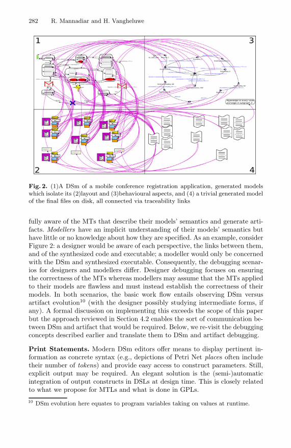
282 R. Mannadiar and H. Vangheluwe
Fig. 2. (1)A DSm of a mobile conference registration application, generated modelswhich isolate its (2)layout and (3)behavioural aspects, and (4) a trivial generated modelof the final files on disk, all connected via traceability links
fully aware of the MTs that describe their models’ semantics and generate arti-facts. Modellers have an implicit understanding of their models’ semantics buthave little or no knowledge about how they are specified. As an example, considerFigure 2: a designer would be aware of each perspective, the links between them,and of the synthesized code and executable; a modeller would only be concernedwith the DSm and synthesized executable. Consequently, the debugging scenar-ios for designers and modellers differ. Designer debugging focuses on ensuringthe correctness of the MTs whereas modellers may assume that the MTs appliedto their models are flawless and must instead establish the correctness of theirmodels. In both scenarios, the basic work flow entails observing DSm versusartifact evolution10 (with the designer possibly studying intermediate forms, ifany). A formal discussion on implementing this exceeds the scope of this paperbut the approach reviewed in Section 4.2 enables the sort of communication be-tween DSm and artifact that would be required. Below, we re-visit the debuggingconcepts described earlier and translate them to DSm and artifact debugging.
Print Statements. Modern DSm editors offer means to display pertinent in-formation as concrete syntax (e.g., depictions of Petri Net places often includetheir number of tokens) and provide easy access to construct parameters. Still,explicit output may be required. An elegant solution is the (semi-)automaticintegration of output constructs in DSLs at design time. This is closely relatedto what we propose for MTLs and what is done in GPLs.
10 DSm evolution here equates to program variables taking on values at runtime.

Debugging in Domain-Specific Modelling 283
(a) (b)
Fig. 3. (a)A high-level construct, its mapping to code, and a possible rendering ofexception translation specification facilities; (b)Stepping into in “designer debug mode”navigates across levels of abstraction
Assertions. Assertions can also be (semi-)automatically specified DSL con-structs. Provisions to enable and disable them, and to halt model animation andartifact execution when they fail are needed. These might be rules or functioncalls and should be generated (and weaved into artifacts) automatically.
Exceptions. Although DSms may be animated, what is truly being executed aresynthesized artifacts. Consequently, exceptions originate from artifacts and aredescribed in terms of their metamodel. Some exceptions may describe irrelevanttransient issues, others may describe issues relevant only to designers. Theirhandling is thus a design choice of the DSL architect. “Silent” exception handlersfor irrelevant exceptions should be generated along with synthesized artifactswhile relevant exceptions should be translated into domain-specific terms andpropagated11 to the modeller or designer (as depicted in Fig. 3a where a low-levelerror message results in updated concrete syntax at the DSm level).
Execution Control. The play, pause, stop and step commands also requiretwo-way communication between DSm and artifact. Playing and stopping sim-ply require means to remotely run or kill the generated model or program. Themeaning of a step in an arbitrary DSm, however, is not obvious. A general defi-nition is that a step constitutes any modification to any parameter of any entityin a DSm. Still, stepping can be considered from two orthogonal perspectives:the modeller’s and the designer’s. On one hand, the three step commands, inconjunction with our general definition, intuitively translate to DSLs which sup-port hierarchy and composition. On the other, generating artifacts from DSmscreates an implicit hierarchy between them. Thus, a designer, may prefer forthe step into operation to take a step at the level of corresponding lower levelentities. This scenario is depicted in Figure 3b where two successive step into
11 The backward links described in Section 4.2 may be instrumental in this propagation.

284 R. Mannadiar and H. Vangheluwe
operations lead a designer from a domain-specific traffic light model entity to acorresponding Statechart state and finally to a function in the generated code.Conversely, stepping out would bring the designer back to higher level entitiesand stepping over would perform a step given the current formalism (e.g., onecode statement, one operational semantics rule). As for the pause command, asensible approach is to pause the execution before running what would have beenthe next step at the DSm level for the modeller, and at the artifact level for thedesigner. These distinct stepping and pausing modes further motivate our previ-ous proposal of separate debugging modes for designers and modellers. Finally,all of the above implies that (ideally automatic) instrumentation of artifacts toenable running only parts of them at a time are required12.
Runtime Variable I/O. Model editing tools can be used to view and modifyDSm and generated model variable values whereas code IDE debugger facilitiescan be used for synthesized coded artifacts. The challenge is to propagate changessuch that consistency is preserved across all levels of abstraction12.
Breakpoints. Breakpoints in state-based languages (e.g., Statecharts) could beset on states. For languages where state is implicit (e.g., Petri Nets whose state istheir marking), however, they could be specified as patterns (pausing executionupon detection). Finally, designers should be able to specify breakpoints at anylevel of abstraction while modellers should be restricted to the DSm level.
Stack Traces. Stack traces remain tightly bound to the step into and out com-mands. Thus, they might display related actions at different levels of abstractionfor designers while reflecting construct composition, if any, for modellers.
5 Conclusion and Future Work
We proposed a mapping between concepts in the software and DSM debuggingrealms. We distinguished between MT and DSm debugging, and between debug-ging scenarios for designers, who are fully aware of the MTs that describe theirmodels’ semantics and generate artifacts, and modellers, who have an implicitunderstanding of their models’ semantics but little or no knowledge about howthey are specified. Our work is meant as a guide for developing DSM debuggers:numerous MT debugger features can be built-in to MTLs and engines, whilemodular TGR-based artifact synthesis can considerably facilitate the implemen-tation of most DSm and artifact debugger facilities. We plan to fully implementthe concepts proposed in this work in AToM3’s successor, AToMPM.
References
1. Brown, A.W.: Model driven architecture: Principles and practice. Software andSystems Modeling (SoSym) 3, 314–327 (2004)
2. Czarnecki, K., Helsen, S.: Feature-based survey of model transformation ap-proaches. IBM Systems Journal (IBMS) 45, 621–645 (2006)
12 Once again, traceability links between DSms and artifacts may be key.

Debugging in Domain-Specific Modelling 285
3. de Lara, J., Vangheluwe, H., Alfonseca, M.: Meta-modelling and graph gram-mars for multi-paradigm modelling in AToM3. Software and Systems Modeling(SoSym) 3, 194–209 (2004)
4. Eisenstadt, M.: “My Hairiest Bug” war stories. Communications of the ACM(CACM) 40, 30–37 (1997)
5. Kelly, S., Tolvanen, J.-P.: Domain-Specific Modeling: Enabling Full Code Genera-tion. Wiley-Interscience, Hoboken (2008)
6. Lengyel, L., Levendovszky, T., Mezei, G., Charaf, H.: Model transformation with avisual control flow language. International Journal of Computer Science (IJCS) 1,45–53 (2006)
7. Mannadiar, R., Vangheluwe, H.: Modular synthesis of mobile device applicationsfrom domain-specific models. In: The 7th International Workshop on Model-BasedMethodologies for Pervasive and Embedded Software, MOMPES (2010)
8. Mannadiar, R., Vangheluwe, H.: Modular synthesis of mobile device applicationsfrom domain-specific models. Technical Report SOCS-TR-2010.5, McGill Univer-sity (2010)
9. Safa, L.: The making of user-interface designer a proprietary DSM tool. In: 7thOOPSLA Workshop on Domain-Specific Modeling (DSM), p. 14 (2007),http://www.dsmforum.org/events/DSM07/papers.html
10. Schurr, A.: Specification of graph translators with triple graph grammars. In: Pro-ceedings of the 20th International Workshop on Graph-Theoretic Concepts in Com-puter Science (1995)
11. Syriani, E., Kienzle, J., Vangheluwe, H.: Exceptional transformations. In: Tratt, L.,Gogolla, M. (eds.) ICMT 2010. LNCS, vol. 6142, pp. 199–214. Springer, Heidelberg(2010)
12. Syriani, E., Vangheluwe, H.: De-/re-constructing model transformation languages.In: 9th International Workshop on Graph Transformation and Visual ModelingTechniques, GT-VMT (2010)
13. Wu, H., Gray, J., Mernik, M.: Grammar-driven generation of domain-specific lan-guage debuggers. Software: Practice and Experience 38, 1073–1103 (2008)
14. Zeller, A.: Why Programs Fail: A Guide to Systematic Debugging, 2nd edn. MorganKaufmann, San Francisco (2009)

COPE – A Workbench for the Coupled
Evolution of Metamodels and Models
Markus Herrmannsdoerfer
Institut fur Informatik, Technische Universitat MunchenBoltzmannstr. 3, 85748 Garching b. Munchen, Germany
Abstract. Model-driven software development promises to increase pro-ductivity by offering modeling languages tailored to a problem domain.Consequently, an increasing number of modeling languages are built us-ing metamodel-based language workbenches. In response to changingrequirements and technologies, the modeling languages and thus theirmetamodels need to be adapted. Manual migration of existing modelsin response to metamodel adaptation is tedious and error-prone. In thispaper, we present our tool COPE to automate the coupled evolution ofmetamodels and models. To not lose the intention behind the adapta-tion, COPE records the coupled evolution in an explicit history model.Based on this history model, COPE provides advanced tool support toinspect, refactor and recover the coupled evolution.
1 Introduction
Model-driven development promises to raise the abstraction level of today’s soft-ware development with the help of the pervasive use of models. Models are builtby using modeling languages that allow the users to directly express the abstrac-tions from their problem domain. To reduce the effort for software development,implementation code can be automatically generated from these models. Re-cent approaches such as Model-Driven Architecture [11], Software Factories [5]and Domain-Specific Modeling [10] advocate to also develop modeling languagesin a model-driven way—using metamodels to define the modeling language’ssyntax. Language workbenches—such as the Eclipse Modeling Project (EMP),Microsoft DSL Tools and MetaCase MetaEdit+—significantly reduce the effortto build tool support for modeling languages around the metamodels. In EMP,for instance, metamodels are built using the Ecore formalism provided by theEclipse Modeling Framework (EMF). As a consequence, an increasing numberof modeling languages is built both in industry and research. These languagesrange from general-purpose modeling languages like UML, over industry-widelanguages like AUTOSAR, to languages used only inside an organization.
Problem. Like software, modeling languages are subject to evolution due tochanging requirements and technological progress [3]. A modeling language isevolved by first adapting its metamodel to the new requirements. Metamodel
B. Malloy, S. Staab, and M. van den Brand (Eds.): SLE 2010, LNCS 6563, pp. 286–295, 2011.c© Springer-Verlag Berlin Heidelberg 2011

COPE – A Workbench for the Coupled Evolution 287
adaptation requires the migration of tools for the modeling language such aseditors and code generators. Most importantly, existing models may need tobe migrated to conform to the adapted metamodel again. Avoiding model mi-gration by downwards-compatible metamodel changes is often a poor solution,since it reduces the quality of the metamodel and thus the modeling language.By contrast, manual migration of models is tedious and error-prone, and there-fore model migration needs to be automated. Building an automated modelmigration—even if highly desired in practice—is a non-trivial task, as it has toensure the preservation of the meaning of a possibly unknown set of models. Thistask is further complicated by the issue that, in current practice, the intentionbehind the metamodel changes is lost in the evolution process.
Contribution. To not lose the intention behind the adaptation, we advocate torecord the metamodel changes throughout the evolution process. In this paper,we present our tool COPE to record the metamodel adaptation together with themodel migration—we call this the coupled evolution of metamodels and models.COPE records the evolution as a sequence of coupled operations in an explicithistory model. Each coupled operation encapsulates both metamodel adaptationas well as reconciling model migration. Recurring coupled operations can bereused to further reduce the effort for building a model migration. Using thehistory model, existing models can be automatically migrated to the adaptedversion of the metamodel. Sometimes the recorded history does not perfectlyspecify the intended model migration—which is found out after testing the modelmigration—and thus needs to be modified. Sometimes the history cannot berecorded and hence needs to be recovered from the metamodel versions beforeand after the adaptation. To address these issues, COPE provides additionaltool support to inspect, refactor and recover the coupled evolution.
2 Related Work
An approach to build a model migration for a metamodel adaptation needsto face two main challenges. First, it should lead to a correct migration whichpreserves the meaning of all models. Second, it should automate the buildingprocess to reduce the effort for model migration.
Manual specification approaches provide transformation languages to manuallyspecify the model migration. Sprinkle presents a visual model transformationlanguage to specify the transformation only for the difference between two meta-model versions [14]. Balasubramanian extends this language with usage pat-terns for typical migration scenarios [12]. The resulting Model Change Language(MCL) comes with the Generic Modeling Environment (GME). Flock is an EMF-based textual model transformation language that also automatically unsetsmodel elements that are no longer conforming to the adapted metamodel [13].While manual specification fosters correctness of the model migration, it alsorequires the most effort.

288 M. Herrmannsdoerfer
Matching approaches try to automatically derive a model migration from thematching between two metamodel versions. Cicchetti presents an EMF-basedtool prototype that can not only derive a model migration for primitive changes,but also for compound changes [2]. Garces presents an EMF-based matchinglanguage that allows the user to customize the matching process and to add newmatching patterns [4]. While difference-based approaches completely automatethe building process, they may not lead to a correct model migration. However,matching approaches can be complemented by manual specification to completeand correct the generated model migration.
Operation-based approaches record the coupled operations which are used toadapt the metamodel and which also encapsulate a model migration. Operation-based approaches provide a compromise for both challenges: They are likelyto lead to a correct migration by means of recording, and at the same timereduce the effort by means of reusable coupled operations. However, they alsorequire integration into the editor for the metamodel. Wachsmuth presents hisEMF-based tool prototype ECORAL that provides a library of reusable coupledoperations [15]. To increase expressiveness, we extended COPE with a meansto specify a custom model migration for a recorded metamodel adaptation [8].Compared to our previous work, in this paper, we introduce additional functionsof COPE to inspect, refactor and recover the coupled evolution.
3 COPE – Coupled Evolution of Metamodels and Models
COPE is implemented based on the widely used Eclipse Modeling Framework(EMF)1. Besides recording the coupled evolution in an explicit history model,COPE provides support to inspect, refactor and recover the coupled evolution.
3.1 Recording the Coupled Evolution
As is depicted in Figure 1, COPE records the metamodel adaptation as a se-quence of primitive changes in an explicit history model [6]. As is depicted inFigure 2, COPE’s user interface—which is directly integrated into the existingEMF metamodel editor—provides access to the recorded history model. COPEsupports two methods to form coupled operations [8], i.e. to attach a modelmigration to a sequence of primitive changes.
Enabling Reuse. Reuse of recurring migration specifications allows to signifi-cantly reduce the effort associated with building a model migration [7]. COPEthus provides reusable coupled operations which encapsulate metamodel adap-tation and model migration in a metamodel-independent way. Reusable coupledoperations are organized in a library which can be extended by declarations ofnew operations. The declaration is made independent of a specific metamodelthrough parameters, and may provide constraints to restrict the applicability of
1 See EMF web site: http://www.eclipse.org/modeling/emf

COPE – A Workbench for the Coupled Evolution 289
Fig. 1. Overview of COPE
the operation. Currently, COPE comes with about 60 reusable coupled opera-tions. The user can adapt the metamodel by applying reusable coupled opera-tions through the operation browser. The operation browser allows the user toset the parameters of a reusable coupled operation, and gives feedback on itsapplicability based on the constraints. When a reusable coupled operation is ex-ecuted, its application is automatically recorded in the history model. Figure 2shows the operation Extract Subclass being selected in the operation browserand recorded to the history model.
Supporting Expressiveness. Specifications of model migration can become sospecific to a certain metamodel that reuse makes no sense [7]. To be able to coverthese specifications, COPE allows the user to manually define a custom coupledoperation. In order to do so, the user has to manually encode a model migrationfor a recorded metamodel adaptation. To encode a model migration, COPEprovides a language expressive enough to cater for complex model migrations [8].The user needs to perform a custom coupled operation only, in case no reusablecoupled operation is available for the change at hand. First, the metamodel isdirectly adapted in the metamodel editor, in response to which the changes areautomatically recorded in the history. A migration can later be attached to thesequence of metamodel changes. Figure 2 shows the migration editor to encodethe custom migration for a metamodel adaptation.
Migrator Generation. A migrator can be generated from the history model thatallows for the batch migration of existing models. The migrator packages thesequence of coupled operations which can be executed to automatically migrateexisting models.

290 M. Herrmannsdoerfer
Fig. 2. User Interface of COPE
3.2 Inspecting the Coupled Evolution
The recorded history model allows the user to understand the intention behindthe metamodel adaptation. Based on the history model, COPE provides thefollowing functions to ease understanding the coupled evolution.
Identifying Breaking Changes. Breaking changes are changes which can possiblyinvalidate existing models [1]. To prevent errors during model migration, thesechanges need to have a model migration attached. COPE provides an analysisto identify breaking changes which do not yet have a model migration attached.Breaking changes are identified on the metamodel-level, i.e. independently of theexisting models.
Metamodel Reconstruction. To understand the evolution, COPE allows the userto reconstruct metamodel versions from the history model. Earlier metamodelversions can be simply reconstructed by interpreting the primitive changes recor-ded in the history model. Thus it is not necessary to store all the intermediatemetamodel versions which would require a large memory footprint. This recon-struction is interactive, allowing the user to browse through the history model.

COPE – A Workbench for the Coupled Evolution 291
When the user selects a change in the user interface, COPE reconstructs thesnapshot of the metamodel right after the change. The metamodel snapshot isshown in a separate view through which it can be inspected.
History Differencing. Comparing two metamodel snapshots in the Eclipse Mod-eling Framework using EMF Compare2 does not always yield an accurate differ-ence model. This is due to the fact that—in the absence of universally uniqueidentifiers—the matching between the metamodel elements from the two snap-shots has to be inferred. To produce a more accurate difference model, the match-ing can be generated from the history model. In the user interface, COPE allowsthe user to select the source and target version for the comparison directly inthe history model. COPE produces a view showing the difference model betweenthe two metamodel versions.
3.3 Refactoring the Coupled Evolution
As the recorded history does not always perfectly specify the intended modelmigration, COPE provides functions to refactor the history model. The refac-torings have to ensure the overall consistency of the history model: the historymodel has to reconstruct the current metamodel version.
Undoing Changes. When performing further changes, earlier changes mightprove to be wrong. Manually performing the reverse changes is a possible solu-tion, but might lead to a different intention when regarding the model migration.For example, deleting an attribute and creating it again would lead to the loss ofthe attribute’s values in the model. Therefore, COPE provides support to undochanges after they have already been recorded. To facilitate undoing changes,the changes are stored in the history model both in forward and reverse direc-tion. Then the changes to be undone need to be simply applied in the reversedirection. To preserve the consistency of the history model, changes can only beundone if no later changes depend on them.
Replacing Changes. For certain breaking changes, we might later identify areusable coupled operation that provides the intended model migration. Ratherthan manually reimplementing the model migration, it is better to apply thereusable coupled operation instead. The primitive changes, however, have al-ready been recorded to the history model. COPE thus provides support to re-place a sequence of primitive changes with the application of a reusable coupledoperation. COPE reconstructs the metamodel version before the changes andpresents it to the user in a dialog where she can select and apply the appropriatereusable coupled operation. To keep the history model consistent, the primitivechanges can only be replaced, if the operation application yields the same result.
Reordering Changes. Only consecutive changes can be replaced by a reusablecoupled operation or can be enriched by a custom model migration. Sometimesthe changes which we want to replace or enrich are not consecutive. Certain
2 See EMF Compare web site: http://wiki.eclipse.org/index.php/EMF_Compare
292 M. Herrmannsdoerfer
changes, however, are independent of each other and thus can be reordered tomake them consecutive. COPE therefore provides support to move changes toanother position in the history model. To ensure the overall consistency of thehistory model, the following constraints need to be fulfilled: The changes canonly be moved to an earlier position, if they do not depend on the changes thatare jumped over, and the changes can only be moved to a later position, if thechanges that are jumped over do not depend on them.
3.4 Recovering the Coupled Evolution
There are certain cases where COPE cannot be used during the adaptation ofthe metamodel. For example, the metamodel might be generated from anotherartifact, and therefore a different tool is used to edit the artifact. In these cases,the history model needs to be recovered from the metamodel versions before andafter the adaptation.
Metamodel Convergence. COPE provides advanced tool support to reverse engi-neer the history model. Figure 3 depicts the user interface to let a source meta-model version converge to a target metamodel version. The source metamodelversion is loaded directly in the metamodel editor, whereas the target metamodelis displayed in a separate view. This view also displays the current differencemodel which results from the comparison between the source and target meta-model using EMF Compare. The differences are linked to the metamodel ele-ments from both source and target version to which they apply. Breaking changesin the difference model—which necessitate a model migration—are highlightedin red. By means of the operation browser, the user can apply reusable coupledoperations to bring the source metamodel nearer to the target metamodel. Afteran operation is executed on the source metamodel, the difference is automaticallyupdated to reflect the changes. Non-breaking changes in the difference model canbe easily applied to the source metamodel by double-clicking on them.
4 Evaluation
The presented functions are motivated from a number of case studies in whichCOPE has been applied. In these case studies, COPE has been applied to eitherreverse or forward engineer the coupled evolution.
Graphical Modeling Framework (GMF) is a widely used open source frameworkfor the model-driven development of diagram editors3. To demonstrate the ap-plicability of COPE, we have reverse engineered the coupled evolution of the fourmetamodels defined by GMF [9]. More specifically, we have applied the functionfor metamodel convergence to facilitate the reverse engineering of the coupledevolution. The resulting coupled evolution covers all the intermediate versionsof the metamodels, meaning that COPE could have been directly applied forthe maintenance of all four metamodels. The GMF case study indicates that,3 See GMF web site: http://www.eclipse.org/modeling/gmf

COPE – A Workbench for the Coupled Evolution 293
Fig. 3. Metamodel Convergence
in practice, most of the coupled evolution can be captured by reusable coupledoperations. Moreover, this case study helped to build an extensive library ofreusable coupled operations.
Palladio Component Model (PCM) is a modeling language for the specificationand analysis of component-based software architectures4. As a second applica-tion of the function for metamodel convergence, we have reverse engineered thecoupled evolution of the metamodel defined by the Palladio Component Model(PCM) [8]. Similar to GMF, most of the coupled evolution could be covered byreusable coupled operations. In contrast to GMF, the resulting coupled evolutiondoes not capture all the intermediate versions of the metamodel, as there werea lot of destructive changes that were reversed at a later instant. To be able todeal with these destructive changes in a clean manner, we have implemented thefunction for undoing changes.
Quamoco is a research project whose goal is to develop a language for model-ing the product quality of software5. Currently, we are applying COPE for theevolutionary development of the metamodel on which the modeling languageis based. The coupled evolution forward engineered by this case study is not
4 See PCM web site: http://www.palladio-approach.net5 See QUAMOCO web site: http://www.quamoco.de

294 M. Herrmannsdoerfer
much different from the reverse engineered metamodel histories: most of thecoupled evolution can still be covered by reusable coupled operations. Many ofthe reusable coupled operations identified in the previous case studies proved tobe useful for the adaptation of the Quamoco metamodel. Furthermore, the func-tions to refactor the coupled evolution showed to be useful to introduce reusablecoupled operations that have been newly identified.
UNICASE is a CASE tool that integrates models from the different develop-ment activities—amongst others, requirements engineering, design and projectplanning—into a unified model6. COPE is applied to forward engineer the cou-pled evolution of the metamodel to which these models conform. To supportmodel evolution, UNICASE records the changes performed on the models andstores them in a repository. When the metamodel is adapted, we thus do notonly have to migrate the models, but also the recorded changes. While COPE’smigration language showed to be expressive enough to specify the change mi-gration, we have extended COPE to be able to refine existing reusable coupledoperations with the appropriate change migration.
5 Conclusion
Just as other software artifacts, modeling languages and thus their metamodelshave to be adapted. To facilitate language evolution, adequate tool support isrequired to automate the migration of models. To obtain a correct model mi-gration, COPE records the coupled evolution of metamodels and models in anexplicit history model. As a result, the history model stores the sequence of cou-pled operations that have been performed during evolution. A coupled operationencapsulates the metamodel adaptation and reconciling model migration. Recur-ring coupled operations can be reused to further reduce the effort for buildinga model migration. To make the operation-based approach usable in practice,more advanced tool support is necessary to maintain the history model. COPEprovides functions to inspect, refactor and recover the history model to betterunderstand, correct and reverse engineer the coupled evolution.
Even if the presented functions have shown to be useful in a number of casestudies, there is still room for further improvement. To facilitate reverse engineer-ing the coupled evolution, we envision a function that automatically proposesreusable coupled operations based on the difference between two metamodel ver-sions. To validate the resulting model migration, we plan to develop a frameworkfor testing the coupled evolution.
COPE is open source and can be obtained from its website7. Moreover, COPEis about to be made available via the newly created Eclipse Project Edapt.
Acknowledgments. We are grateful to Daniel Ratiu for providing feedback on ear-lier versions of this paper. The presented work was partially funded by the Ger-man Federal Ministry of Education and Research (BMBF), grants “SPES2020,01IS08045A” and “Quamoco, 01IS08023B”.6 See UNICASE web site: http://www.unicase.org7 See COPE web site: http://cope.in.tum.de
COPE – A Workbench for the Coupled Evolution 295
References
1. Becker, S., Goldschmidt, T., Gruschko, B., Koziolek, H.: A process model andclassification scheme for semi-automatic meta-model evolution. In: Proc. 1st Work-shop MDD, SOA und IT-Management (MSI 2007), pp. 35–46. GiTO-Verlag (2007)
2. Cicchetti, A., Ruscio, D.D., Eramo, R., Pierantonio, A.: Automating co-evolution inmodel-driven engineering. In: 12th Intl. Enterprise Distributed Object ComputingConference (EDOC 2008). IEEE, Los Alamitos (2008)
3. Favre, J.M.: Languages evolve too! changing the software time scale. In: 8th Intl.Workshop on Principles of Software Evolution, pp. 33–42 (2005)
4. Garces, K., Jouault, F., Cointe, P., Bezivin, J.: Managing model adaptation byprecise detection of metamodel changes. In: Paige, R.F., Hartman, A., Rensink, A.(eds.) ECMDA-FA 2009. LNCS, vol. 5562, pp. 34–49. Springer, Heidelberg (2009)
5. Greenfield, J., Short, K., Cook, S., Kent, S.: Software Factories: Assembling Appli-cations with Patterns, Models, Frameworks, and Tools. Wiley, Chichester (2004)
6. Herrmannsdoerfer, M.: Operation-based versioning of metamodels with COPE. In:2nd Intl. Workshop on Comparison and Versioning of Software Models (CVSM2009), pp. 49–54. IEEE, Los Alamitos (2009)
7. Herrmannsdoerfer, M., Benz, S., Juergens, E.: Automatability of coupled evolutionof metamodels and models in practice. In: Busch, C., Ober, I., Bruel, J.-M., Uhl,A., Volter, M. (eds.) MODELS 2008. LNCS, vol. 5301, pp. 645–659. Springer,Heidelberg (2008)
8. Herrmannsdoerfer, M., Benz, S., Juergens, E.: COPE - automating coupledevolution of metamodels and models. In: Drossopoulou, S. (ed.) ECOOP 2009.LNCS, vol. 5653, pp. 52–76. Springer, Heidelberg (2009)
9. Herrmannsdoerfer, M., Ratiu, D., Wachsmuth, G.: Language evolution in practice:The history of GMF. In: van den Brand, M., Gasevic, D., Gray, J. (eds.) SLE 2009.LNCS, vol. 5969, pp. 3–22. Springer, Heidelberg (2010)
10. Kelly, S., Tolvanen, J.P.: Domain-Specific Modeling. Wiley, Chichester (2007)11. Kleppe, A.G., Warmer, J., Bast, W.: MDA Explained: The Model Driven Archi-
tecture: Practice and Promise. Addison-Wesley, Reading (2003)12. Narayanan, A., Levendovszky, T., Balasubramanian, D., Karsai, G.: Automatic
domain model migration to manage metamodel evolution. In: Schurr, A., Selic, B.(eds.) MODELS 2009. LNCS, vol. 5795, pp. 706–711. Springer, Heidelberg (2009)
13. Rose, L.M., Kolovos, D.S., Paige, R.F., Polack, F.A.C.: Model migration withepsilon flock. In: Tratt, L., Gogolla, M. (eds.) ICMT 2010. LNCS, vol. 6142, pp.184–198. Springer, Heidelberg (2010)
14. Sprinkle, J., Karsai, G.: A domain-specific visual language for domain model evo-lution. Journal of Visual Languages and Computing 15(3-4), 291–307 (2004)
15. Wachsmuth, G.: Metamodel adaptation and model co-adaptation. In: Bateni, M.(ed.) ECOOP 2007. LNCS, vol. 4609, pp. 600–624. Springer, Heidelberg (2007)

DSLTrans: A Turing Incomplete Transformation
Language
Bruno Barroca1, Levi Lucio2, Vasco Amaral1,Roberto Felix1, and Vasco Sousa1
1 CITI, Departamento de Informatica, Faculdade de Ciencias e TecnologiaUniversidade Nova de Lisboa, Portugal
2 LASSY, University of Luxembourg, [email protected],
{Bruno.Barroca,Vasco.Amaral,Roberto.Felix,Vasco.Sousa}@di.fct.unl.pt
Abstract. In this paper we present DSLTrans: a visual language anda tool for model transformations1 . We aim at tackling a couple of im-portant challenges in model transformation languages — transformationtermination and confluence. The contribution of this paper is the propo-sition of a transformation language where all possible transformationsare guaranteed to be terminating and confluent by construction. The re-sulting transformation language is simple, turing incomplete and includestransformation abstractions to support transformations in a software lan-guage engineering context. Our explanation of DSLTrans includes a com-plete formal description of our visual language and its properties.
Keywords: Model Transformations, Turing Incompleteness, Termina-tion, Confluence.
1 Introduction
A problem in modern model transformation languages that has recently receivedsome attention is to how to guarantee that a transformation terminates. Becausethe semantics of transformation languages are usually based on graph grammars,the termination problem is in general undecidable [7]. Termination has been de-scribed in [6] as one of the ’quality requirements for a transformation languageor tool ’. The problem has been approached by several authors [2,3,4] who haveproposed criteria that can be applied to decide about the termination of transfor-mations under particular conditions. The EMFTrans tool [1] presents a completeformalization of all concepts involved in a transformation and it is possible un-der certain conditions to decide if a given transformation is locally confluent andterminates.1 This work has been developed in the context of project BATIC3S partially funded
by the Portuguese FCT/MCTES ref. PTDC/EIA/65798/2006, the doctoral grantref. SFRH/BD/38123/2007, the post doctoral grant ref. SFRH/BPD/65394/2009and the Luxembourguese FNR/CORE project MOVERE ref. C09/IS/02.
B. Malloy, S. Staab, and M. van den Brand (Eds.): SLE 2010, LNCS 6563, pp. 296–305, 2011.c© Springer-Verlag Berlin Heidelberg 2011

DSLTrans: A Turing Incomplete Transformation Language 297
In this paper we propose an ’egg of Columbus’ approach to the terminationproblem by building a visual transformation language called DSLTrans whichguarantees that the number of steps in a model transformation is always finite.As a consequence, any transformation expressed in our language will alwaysend. We also guarantee by construction the confluence of any model transforma-tion written in DSLTrans, which is an important correctness property of modeltransformations as mentioned in [3]. DSLTrans is, by construction, a turing in-complete language. This is due to the fact that our language is free of loop orrecursion constructs. The work presented in this paper provides the basis for thework we present in [5], where a technique for proving properties of the type ’if astructural relation between some elements of the source model holds, then anotherstructural relation between some elements of the target model should also hold ’is presented. By proposing such a technique we are able to provide additional’success criteria for a transformation language or tool ’ [6], which is the abilityto verify our model transformations.
The rest of this paper is organized as follows. In section 2, we informallydescribe the syntax and semantics of DSLTrans; In section 3, we describe themathematical underpinnings of our transformation language; Finally, in section 4we summarize and discuss future work.
2 Language Overview
Let us present the DSLTrans language with a simple example.
Fig. 1. Metamodels of a squad of agents(left) and a squad organized by gender(right)
Figure 1 presents two metamodels of languages for describing views over theorganization of a police station. The metamodel annotated with ’OrganizationLanguage’ represents a language for describing the chain of command in a po-lice station, which includes male (Male class) and female officers (Female class).The metamodel annotated with ’Gender Language’ represents a language for de-scribing a different view over the chain of command, where the officers workingat the police station are classified by gender. In figure 2 we present a transforma-tion written in DSLTrans between models of both languages. The purpose of this

298 B. Barroca et al.
Fig. 2. A model transformation expressed in DSLTrans using a concrete visual syntaxof an Eclipse diagrammatic editor [8]
transformation is to flatten a chain of command given in language ’OrganizationLanguage’ into two independent sets of male and female officers. Within each ofthose sets the command relations are kept, i.e. a female officer will be directlyrelated to all her female subordinates and likewise for male officers.
An example of an instance of this transformation can be observed in figure 3,where the original model is on the left and the transformed one on the right.Notice that the elements s, mk and fk in the figure on the left are instances of thesource metamodel elements Station, Male and Female respectively (in figure 1).The primed elements in the figure on the right are their instance counterpartsin the target metamodel.
A transformation in DSLTrans is formed by a set of input model sources calledfile-ports (’inputSquad.xmi’ in figure 2) and a list of layers (’Basic entities’ and’Relations’ layers in figure 2). Both layers and file-ports are typed according tometamodels. DSLTrans executes sequentially the list of layers of a transforma-tion specification. A layer is a set of transformation rules, which executes ina non-deterministic fashion. Each transformation rule is a pair (match, apply)where match is a pattern holding elements from the source metamodel, andapply is a pattern holding elements of the target metamodel. For example, inthe transformation rule ’Stations’ in the ’Basic entities’ layer (in figure 2) thematch pattern holds one ’Station’ class from the ’Squad Organization Language’metamodel — the source metamodel; the apply pattern holds one ’Station’ classfrom the ’Squad Gender Language’ metamodel — the target metamodel. Thismeans that all elements in the input source which are of type ’Station’ of the

DSLTrans: A Turing Incomplete Transformation Language 299
Fig. 3. Original model (left) and transformed model (right)
source metamodel will be transformed into elements of type ’Station’ of thetarget metamodel.
Let us first define the constructs available for building transformation rules’match patterns. We will illustrate the constructs by referring to the transforma-tion in figure 2.
– Match Elements : are variables typed by elements of the source metamodelwhich can assume as values elements of that type (or subtype) in the inputmodel. In our example, a match element is the ’Station’ element in the’Stations’ transformation rule of layer ’Basic Entities’ layer;
– Attribute Conditions : conditions over the attributes of a match element;– Direct Match Links: are variables typed by labelled relations of the source
metamodel. These variables can assume as values relations having the samelabel in the input model. A direct match link is always expressed betweentwo match elements;
– Indirect Match Links: indirect match links are similar to direct match links,but there may exist a path of containment associations between the matchedinstances. In our implementation, the notion of indirect links captures onlyEMF containment associations. In our example, indirect match links arerepresented in all the transformation rules of layer ’Relations’ as dashedarrows between elements of the match models;
– Backward Links : backward links connect elements of the match and theapply models. They exist in our example in all transformation rules in the’Relations’ layer, depicted as dashed vertical lines. Backward links are usedto refer to elements created in a previous layer in order to use them in thecurrent one. An important characteristic of DSLTrans is that throughout allthe layers the source model remains intact as a match source. Therefore, theonly possibility to reuse elements created from a previous layer is to referencethem using backward links;
– Negative Conditions : it is possible to express negative conditions over matchelements, backward, direct and indirect match links.
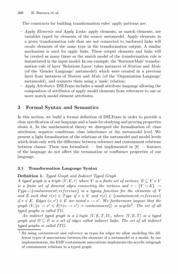
300 B. Barroca et al.
The constructs for building transformation rules’ apply patterns are:
– Apply Elements and Apply Links : apply elements, as match elements, arevariables typed by elements of the source metamodel. Apply elements ina given transformation rule that are not connected to backward links willcreate elements of the same type in the transformation output. A similarmechanism is used for apply links. These output elements and links willbe created as many times as the match model of the transformation rule isinstantiated in the input model. In our example, the ’StationwMale’ transfor-mation rule of layer ’Relations Layer’ takes instances of Station and Male(of the ’Gender Language’ metamodel) which were created in a previouslayer from instances of Station and Male (of the ’Organization Language’metamodel), and connects them using a ’male’ relation;
– Apply Attributes : DSLTrans includes a small attribute language allowing thecomposition of attributes of apply model elements from references to one ormore match model element attributes.
3 Formal Syntax and Semantics
In this section, we build a formal definition of DSLTrans in order to provide aclear specification of our language and a basis for studying and proving propertiesabout it. In the mathematical theory we disregard the formalization of: classattributes; negative conditions; class inheritance at the metamodel level. Wepresent a light formalization of the relations at the metamodel and model levelswhich deals only with the difference between reference and containment relationsbetween classes. These non formalized — but implemented in [8] — featuresof the language do not affect the termination or confluence properties of ourlanguage.
3.1 Transformation Language Syntax
Definition 1. Typed Graph and Indirect Typed GraphA typed graph is a triple 〈V, E, τ〉 where V is a finite set of vertices, E ⊆ V × Vis a finite set of directed edges connecting the vertices and τ : {V ∪ E} →Type ∪ {containment, reference} is a typing function for the elements of Vand E such that τ(v) ∈ Type if v ∈ V and τ(e) ∈ {containment, reference}if e ∈ E. Edges (v, v′) ∈ E are noted v → v′. We furthermore impose that thegraph 〈V, {v → v′ ∈ E|τ(v → v′) = containment}〉 is acyclic2. The set of alltyped graphs is called TG.
An indirect typed graph is a 4-tuple 〈V, E, T, Il〉, where 〈V, E, T 〉 is a typedgraph and Il ⊆ E is a set of edges called indirect links. The set of all indirecttyped graphs is called ITG.2 By using containment and reference as types for edges we allow modeling the dif-
ferent types of associations between the elements of a metamodel or a model. In ourimplementation, the EMF containment associations implements the acyclic subgraphof containment relations in a typed graph.

DSLTrans: A Turing Incomplete Transformation Language 301
Definition 2. Typed Graph UnionLet 〈V, E, τ〉, 〈V ′, E′τ ′〉 ∈ TG be typed graphs. The typed graph union is thefunction � : TG× TG→ TG defined as:
〈V, E, τ〉 � 〈V ′, E′, τ ′〉 = 〈V ∪ V ′, E ∪ E′, τ ∪ τ ′〉
Definition 3. Typed Subgraph and Indirect Typed SubgraphLet 〈V, E, τ〉 = g, 〈V ′, E′, τ ′〉 = g′ ∈ TG be typed graphs. g′ is a typed subgraphof g, written g′ � g, iff V ′ ⊆ V , E′ ⊆ E and τ ′ = τ |V ′.An indirect typed graph 〈V ′, E′, τ ′, Il〉 ∈ ITG is an indirect typed subgraph of atyped graph 〈V, E, τ〉 ∈ TG, written 〈V ′, E′, τ ′, Il〉� 〈V, E, τ〉 iff:
1. 〈V ′, E′ \ Il, τ ′〉 � 〈V, E, τ〉2. if vi → v′i ∈ Il then there exists v → v′ ∈ E∗
c where τ(vi) = τ(v), τ(v′i) =τ(v′) and E∗
c is obtained by the transitive closure of Ec = {v → v′ ∈ E|τ(v →v′) = containment}.
Definition 4. Typed Graph EquivalenceLet 〈V, E, τ〉 = g, 〈V ′, E′, τ ′〉 = g′ ∈ TG be typed graphs. g and g′ are equivalent,written g ∼= g′, iff there is a graph isomorphism f : V → V ′ of graphs 〈V, E〉 and〈V ′, E′〉 such that ∀x ∈ V ∪ E . τ(x) = τ ′(f(x)) and ∀x′ ∈ V ′ ∪ E′ . τ ′(x′) =τ(f−1(x′))
More informally, two typed graphs are defined equivalent if they have the sameshape and related vertices and edges have the same type.
Definition 5. Typed Graph InstanceLet 〈V, E, τ〉 = g, 〈V ′, E′, τ〉 = g′ ∈ TG be typed graphs. g′ is a typed graphinstance of g, written g′ � g, iff for all v′1 → v′2 ∈ E′ there is a v1 → v2 ∈ Esuch that τ(v′
1) = τ(v1), τ(v′2) = τ(v2) and τ(v′1 → v′2) = τ(v1 → v2).
Notice that we only enforce that connections between vertices of g′ must existalso in g and have the same type.
Definition 6. Metamodel and ModelA metamodel 〈V, E, τ〉 ∈ TG is a typed graph where τ is a bijective typing func-tion. The set of all metamodels is called META.
A model is a 4-tuple 〈V, E, τ, M〉 where 〈V, E, τ〉 is a typed graph. More-over M = 〈V ′, E′, τ ′〉 ∈ META is a Metamodel and the codomain of τ equalsthe codomain of τ ′. Finally 〈V, E, τ〉 � M , which means 〈V, E, τ〉 is an in-stance of a metamodel M . The set of all models for a metamodel M is calledMODELM .
Definition 7. Match-Apply ModelA Match-Apply Model is a 6-tuple 〈V, E, τ, Match, Apply, Bl〉, where Match =〈V ′, E′, τ ′, s〉 and Apply = 〈V ′′, E′′, τ ′′, t〉 are models and 〈V, E, τ〉=〈V ′, E′, τ ′〉�〈V ′′, E′′, τ ′′〉. Edges Bl ⊆ V ′ × V ′′ ⊆ E are called backward links. s is called

302 B. Barroca et al.
the source metamodel and t the target metamodel. The set of all Match-Applymodels for a source metamodel s and a target metamodel t is called MAM s
t .Vertices in the Apply model which are not connected to backward links are calledfree vertices. The back : MAM s
t →MAM st function connects all vertices in the
Match model to all free vertices with backward link edges.
The Match part of a match-apply model is used to hold the immutable sourcemodel during a transformation. The Apply part is used to hold the intermediateresults of the transformation.
Definition 8. Transformation RuleA Transformation Rule is a 7-tuple 〈V, E, τ, Match, Apply, Bl, Il〉, where 〈V,E, τ, Match, Apply, Bl〉 ∈MAMs
t is a match-apply model. Match = 〈V, E, τ, M〉and the edges Il ⊆ E are called indirect links (see definition 3). The set of alltransformation rules is called TRs
t . The strip : TRst → TRs
t function removesfrom a transformation rule all free vertices and associated edges.
We define a transformation rule as a kind of match-apply model which allowsindirect links in the match pattern.
Definition 9. Layer, TransformationA layer is a finite set of transformation rules tr ⊆ TRs
t . The set of all layers for asource metamodel s and a target metamodel t is called Layers
t . A transformationis a finite list of layers denoted [l1 :: l2 :: . . . :: ln] where lk ∈ Layers
t and1 ≤ k ≤ n. The set of all transformations for a source metamodel s and a targetmetamodel t is called Transformations
t .
We naturally extend the notion of union (definition 2) to models (definition 6),match-apply models (definition 7) and transformation rules (definition 8). Wealso extend the notion of indirect typed subgraph (definition 3) to transformationrules (definition 8) and match-apply models (definition 7). Finally, we extendthe notion of typed graph equivalence (definition 4) to transformation rules(definition 8).
3.2 Transformation Language Semantics
Definition 10. Match FunctionLet m ∈MAMs
t be a model and tr ∈ TRst be a transformation rule. The match :
MAM st × TRs
t → P(TRst ) is defined as follows:
matchtr(m) = remove({
g | g � m ∧ g ∼= strip(tr)})
Due to the fact that the ∼= relation is based on the notion of graph isomorphism,permutations of the same match result may exist in the
{g | g�m∧g ∼= strip(tr)
}set. The — undefined — remove : P(TRs
t ) → P(TRst ) function is such that it
removes such undesired permutations.

DSLTrans: A Turing Incomplete Transformation Language 303
Definition 11. Apply FunctionLet m ∈ MAMs
t be a match-apply model and tr ∈ TRst a transformation. The
apply : MAMst × TRs
t →MAMst is defined as follows:
et m ∈MAM st be a match-apply model and tr ∈ TRs
t a transformation. Theapply : MAMs
t × TRst →MAMs
t is defined as follows:
applytr(m) =⊔
g∈matchtr(m)
back(g � gΔ)
where gΔ is such that g � gΔ∼= tr
The freshly created vertices of gΔ in the flattened applytr(m) set are disjoint.
Definitions 10 and 11 are complementary: the former gathers all subgraphs of amatch-apply graph which match a transformation rule; the latter builds the newinstances which are created by applying that transformation rule as many timesas the number of subgraphs found by the match function. The strip function isused to enable matching over backward links but not elements to be created bythe transformation rule. The back function connects all newly created verticesto the elements of the source model that originated them.
Definition 12. Layer Step SemanticsLet l ∈ Layer be a Layer. The layer step relation
layerstep→ ⊆ MAM st × TRs
t ×MAM s
t is defined as follows:
tr ∈ l, applytr(m) = m′′′,
〈m,m′,∅〉 layerstep−−−−−→m�m′〈m,m′′�m′′′,l\{tr}〉 layerstep−−−−−→m′
〈m,m′′,l〉 layerstep−−−−−→m′
where {m, m′, m′′} ⊆MAMst are match-apply models.
The freshly created vertices in m′′′ are disjoint from those in m′′.
For each layer we go through all the transformation rules and build for each oneof them the set of new instances created by their application. These instancesare built using the apply function in the second rule of definition 12. The new in-stance results of the apply function for each transformation rule are accumulateduntil all transformation rules are treated. Then, the first rule of definition 12 willmerge all the new instances with the starting match-apply model. The mergeis performed by uniting (using the non-disjoint � union) match-apply graphsincluding the new instances with the starting match-apply model.
Definition 13. Transformation Step SemanticsLet [l :: R] ∈ Transformations
t be a Transformation, where l ∈ Layerst is a
Layer and R a list. The transformation step relationtrstep→ ⊆ MAMs
t × TRst ×
MAM st is defined as follows:

304 B. Barroca et al.
〈m,[]〉 trstep−−−→m
⟨m,〈∅,∅,∅,∅,∅,∅〉,l
⟩layerstep−−−−−→m′′, 〈m′′,R〉 trstep−−−→m′
〈m,[l::R]〉 trstep−−−→m′
where {m, m′, m′′} ⊆MAMst are match-apply models.
A model transformation is a sequential application of transformation layers toa match-apply model containing the source model and an empty apply model.The transformation output is the apply part of the resulting match-apply model.
Definition 14. Model TransformationLet ms ∈MODELs and mt ∈MODELt be models andtr ∈ Transformations
t be a transformation. A model transformationtransf→ ⊆
MODELs × Transformationst ×MODELt is defined as follows:
ms, trtransf−−−−→ mt ⇔ 〈V, E, τ, ms, ∅, ∅〉, tr trstep−−−−→ 〈V, E, τ, ms, mt, Bl〉
We now prove two important properties about DSLTrans’ transformations.
Proposition 1. ConfluenceEvery model transformation is confluent regarding typed graph equivalence.
Proof. (Sketch) We want to prove that for every model transformation tr ∈Transformations
t having as input a model ms ∈MODELs, if ms, trtransf−−−−→ mt
and ms, trtransf−−−−→ m′
t then mt∼= m′
t. Note that we only have to prove typedgraph equivalence between mt and m′
t because the identifiers of the objects pro-duced by a model transformation are irrelevant.If we assume ¬(mt
∼= m′t) then this should happen because of non-determinism
points in the rules defining the semantics of a transformation: 1) in definition 11gΔ is non-deterministic up to typed graph equivalence, which does not contra-dict the proposition; 2) in definition 12 transformation rule tr is chosen non-deterministically from layer l. Thus, the order in which the transformation rulesare treated is non-deterministic. However, the increments to the transformationby each rule of a layer are united using �, which is commutative and thus rendersthe transformation result of each layer deterministic. Since there are no otherpossibilities of non-determinism points in the semantics of a transformation,¬(mt
∼= m′t) provokes a contradiction and thus the proposition is proved. �
Proposition 2. TerminationEvery model transformation terminates.
Proof. (Sketch) Let us assume that there is a transformation which does not ter-minate. In order for this to happen there must exist a section of the semanticsof that transformation which induces an algorithm with an infinite amount ofsteps. We identify three points of a transformation’s semantics where this canhappen: 1) if definition 13 induces an infinite amount of steps. The only possi-bility for this to happen is if the transformation has an infinite amount of layers,

DSLTrans: A Turing Incomplete Transformation Language 305
which is a contradiction with definition 9; 2) if definition 12 induces an infiniteamount of steps. The only possibility for this to happen is if a layer has an infi-nite amount of transformation rules, which is a contradiction with definition 8;3) if the result of the matchtr(m) function in definition 10 is an infinite set ofmatch-apply graphs. The match-apply graph m is by definition finite, thus thenumber of isomorphic subgraphs of m is infinite only if the transitive closure ofcontainment edges of m is infinite. The only possibility for this to happen is ifthe graph induced by the containment edges of m has cycles, which contradictsdefinition 1. Since there are no more points in the semantics of a transformationthat can induce an infinite amount of steps, the proposition is proved. �
4 Conclusions and Future Work
We have presented DSLTrans, a turing incomplete transformation language witha mathematical underpinning which guarantees transformation termination andconfluence by construction. With this language, we have introduced interestingabstractions such as layers, backward and indirect links. An important side effectof DSLTrans not being a turing complete language is the fact that verificationof properties about our transformations are possible.Our efforts are now focused on the optimization of the efficiency of the transfor-mation engine itself, and we will perform a thorough validation on the usabilityaspects of this language in several transformation use cases.
References
1. Biermann, E., Ermel, C., Taentzer, G.: Precise Semantics of EMF Model Transfor-mations by Graph Transformation. In: Busch, C., Ober, I., Bruel, J.-M., Uhl, A.,Volter, M. (eds.) MODELS 2008. LNCS, vol. 5301, pp. 53–67. Springer, Heidelberg(2008)
2. Ehrig, H., Ehrig, K., Prange, U., Taentzer, G.: Fundamentals of Algebraic GraphTransformation. Springer, Heidelberg (2006)
3. Ehrig, H., Ehrig, K., de Lara, J., Taentzer, G., Varro, D., Varro-Gyapay, S.: Termi-nation criteria for model transformation. In: Cerioli, M. (ed.) FASE 2005. LNCS,vol. 3442, pp. 49–63. Springer, Heidelberg (2005)
4. Levendovszky, T., Prange, U., Ehrig, H.: Termination criteria for dpo transfor-mations with injective matches. Electronic Notes in Theoretical Computer Sci-ence 175(4), 87–100 (2007)
5. Lucio, L., Barroca, B., Amaral, V.: A technique for automatic validation of modeltransformations. In: Petriu, D.C., Rouquette, N., Haugen, Ø. (eds.) MODELS 2010.LNCS, vol. 6394, pp. 136–150. Springer, Heidelberg (2010)
6. Mens, T., Van Gorp, P.: A taxonomy of model transformation. Electronic Notes inTheoretic Computer Science 152, 125–142 (2006)
7. Plumpf, D.: Termination of graph rewriting is undecidable. Fundamenta Informat-icae 33(2), 201–209 (1998)
8. Solar Group. Dsltrans plug-in (2010), http://solar.di.fct.unl.pt/twiki/pub/
BATICCCS/ReleaseFiles/dsltrans.october,zip

Translator Generation Using ART
Adrian Johnstone and Elizabeth Scott
Royal Holloway, University of London, Egham, Surrey, TW20 0EX, UK{a.johnstone,e.scott}@rhul.ac.uk
Abstract. ART (Ambiguity Resolved Translators) is a new translatorgenerator tool which provides fast generalised parsing based on an ex-tended GLL algorithm and automatic generation of tree traversers formanipulating abstract syntax. The input grammars to ART comprisemodular sets of context free grammar rules, enhanced with regular ex-pressions and annotations that describe disambiguation and tree mod-ification operations using the TIF (Tear-Insert-Fold) formalism. ARTgenerates a GLL parser for the input grammar along with an outputgrammar whose derivation trees are the abstract trees specified by theTIF tree modification operations.
1 Introduction
ART is an integrated generalised parser generator and tree rewriter. ART sup-ports the traditional applications for parser generators (such as compiler frontend generation) by providing high performance parsing coupled with parsergeneration times that are typically less than the time needed to compile thegenerated code. ART is the first full-scale implementation of both the GLL al-gorithm [2] and the TIF formalism [3].
Existing generalised parser generators typically use a variant of bottom-upGLR parsing; for example, in ASF+SDF [6], Stratego [1] and Elkhound[4]; evenBison has a partial GLR mode. We have described elsewhere improvements tothe GLR algorithm that provide worst-case cubic performance using binarisedSPPF’s but recognise that users find shift-reduce automata hard to understand.GLL is a generalisation of recursive descent that also provides worst-case cubicperformance with linear performance on LL(1) parts of a grammar: in practicewe find that GLL runs approximately as fast as our BRNGLR parsers.
An ART-generated parser or treewalker, Π , performs the following steps (i)lexical analysis of string characters or tree labels into tokens; (ii) parsing of thosetokens against the grammar to form a Shared Packed Parse Forest (SPPF) ofderivations; (iii) disambiguation of the potentially many derivations into a singlederivation tree; (iv) restructuring of that derivation tree using the TIF operatorsto form a restructured derivation tree (RDT); (v) semantics evaluation.
This paper is mostly concerned with step (iv). The GLL algorithm used instep (ii) was presented at LDTA09 [2] and we shall discuss disambiguation in afuture presentation.
On each run, ART produces a parser or treewalker for its input grammar,along with a TIF Transformed Grammar (TTG) which completely describes the
B. Malloy, S. Staab, and M. van den Brand (Eds.): SLE 2010, LNCS 6563, pp. 306–315, 2011.c© Springer-Verlag Berlin Heidelberg 2011

Translator Generation Using ART 307
family of trees that can be constructed by that parser or tree walker. A TTG isitself a TIF grammar, and can thus be used as input to ART, usually after TIFoperators specifying the next phase of tree reworking have been added.
The idea is that parsing and tree transformation can be broken down intoa series of distinct phases, allowing separation of concerns, but using a singlenotation and conceptually identical processing at each stage. Our goal is to havea system which is theoretically well founded, but which software engineers andcasual users find approachable. The TIF operators are based on the notions oftearing and folding trees using three simple local transforms, coupled with theability to insert arbitrary tree fragments.
Consider the construction of a C++ to ANSI-C converter such as CFrontor of an intermediate language converter such as CIL [5] which simplifies andnormalises C++ into a core sub-language in which, for instance, all loops arerepresented by a single form. We envisage writing such converters as a numberof distinct phases, for instance one to handle loop constructs and another torework data scoping. This separation of concerns between phases allows bettertesting and in principle reduces the opportunities for unexpected interactions be-tween tree restructurings. We illustrate the process here as a chain of parser/treewalkers Π0, Π1, . . . with associated TTG’s Γ1, Γ2, . . .. At each stage, we envisagethe software engineer intervening by adding TIF annotations and by factoring,deleting or multiplying out rules to form a Γ ′
i . This process is marked by dashedlines.
σ �
Γ0 Γ ′0
� ART
�Π0
� τ1 �
� Γ1 Γ ′1
� ART
�Π1
� τ2 �
� Γ2 Γ ′2
� �
�
ART
�Π2
� � �
The initial inputs are a concrete grammar Γ0 (say, the ANSI-C standard gram-mar) and a string σ to be parsed. The translator designer adds TIF annotationsto specify the first intermediate form and semantic actions to be executed overtrees from that intermediate form. ART then generates a GLL parser/TIF RDTbuilder Π0 which processes σ to produce an RDT τ1. ART also produces theTTG Γ1 which specifies the full range of τ intermediate forms that can arisefrom Π0. Further annotation and reworking of Γ1 to Γ ′
1 provides the input tothe next stage.
There are significant open questions concerning change management with thisapproach. As things stand, if a change is made to the grammar is an early phase,the contingent changes to TIF annotations will have to be manually propagatedthroughout the chain. Ideally we would have some meta-TIF notation that couldspecify the TIF annotations and thus reapply them automatically. At presentwe are attempting to gain experience with the ‘manual’ approach before tryingto abstract a meta-notation.

308 A. Johnstone and E. Scott
Part of the motivation for ART comes from our experience of manually con-structing simplified equivalent grammars for complex languages such as the C-like assembler for Analog Device’s digital signal processor line. Our asm21tocreverse compiler started off with a detailed context free grammar (CFG) thatcaptured in the syntax many constraints that arise from the hardware of thoseprocessors: for instance shifter operations and arithmetic operations use differentsets of input and output registers. We then moved to a grammar which formallyaccepted a larger language in which, amongst other things, any register couldsupply the operands for any operator. This widened grammar was safe to usebecause any real program had already been parsed for correctness by the tightgrammar: the fact that the grammar could accept programs that were strictlyillegal was of no consequence because they had already been filtered out. Thewidened grammar concentrated operand fetch semantics into one rule, ratherthan the complicated case analysis that we would have had to implement withthe ‘real’ grammar.
An important feature of our approach in ART is that the tool provides notonly a parser, but a formal description of the parser’s output which is guaranteedto be complete. A common failure mode when writing systems based on treerearrangement is to forget about some obscure or infrequently used special case.For instance, a tree-walker based code generator must be able to completely tileany possible intermediate tree with target instructions, and proving that everypossible case has been covered is hard if we use ad hoc mappings. An engineerworking with ART is presented with a grammar which completely describesall possible output trees at each stage of a compiler: by ensuring that everyproduction has appropriate rewrites or semantics, complete coverage is assured.
2 Source Syntax, Modularity and Parsing
The ART source syntax mostly follows the conventions of our earlier RDP andGTB toolkits with added support for modularisation and lexical level rules.We have also created the tools gramex and gramconv which extract grammarrules from electronically readable standards documents and convert them to thesource syntax for a variety of tools including Bison, ASF+SDF, GTB and ART;optionally converting EBNF to BNF using a variety of idioms. These tools andextracted grammars for multiple standardisations of Java, C, C++ and Pascal.are available from
http://www.cs.rhul.ac.uk/research/languages/projects/grammars/index.html
An ART specification comprises one or more modules with associated import andexport lists. In software engineering, modularisation is used to allow separation ofconcerns, to encapsulate and abstract away from details, and to support reuse;we believe that the engineering of large grammar-based systems also benefitsfrom effective modularisation. A complete example of an ART specification fora tiny language is shown on page 313.
ART grammar rules use conventional CFG syntax augmented with the postfixregular operators *, + and ? for Kleene closure, positive closure and optional

Translator Generation Using ART 309
items respectively, as well as parentheses and the | operator to allow alternatesto be gathered together. The symbol # represents the empty string ε. We alsoprovide the form A@B which is shorthand for A (B A)*.
To support scannerless parsing, terminals come in three forms. The most fun-damental is the character terminal denoted by a back-quote followed by eithera printable character or one of the ANSI-C conventional character escape se-quences. These are designed to be used in lexical level specifications and we alsoallow the shorthands ‘x-‘z and \‘x to represent sets of character tokens in therange x through z and the set that includes all character tokens except x. Therange operator may only be applied between operands that are either both dig-its, both lowercase or both uppercase characters because ART does not expectany other sequences to have a portable ordering.
Whether ART uses a separate lexer, specified in this way, or deploys the GLLalgorithm right down to character level (in the manner of scannerless parsingin SDF [7]) is user selectable: there are theoretical and engineering implicationswhich are beyond the scope of this paper but which will be discussed in futurepresentations.
Case sensitive terminals are demarcated by single quotes, and represent ashorthand for a whitespace nonterminal followed by the sequence of characterterminals corresponding to the pattern of the terminal; that is ’while’ is justshorthand for (artWhiteSpace ‘w ‘h ‘i ‘l ‘e).
The nonterminal artWhiteSpace is predefined by ART to correspond to thenonprinting characters; if the user provides explicit productions then the internaldefault is suppressed. ART specifications are modular, as we describe in the nextsection, and each module may have its own artWhiteSpace definition.
Case insensitive terminals are demarcated by double quotes, and representa shorthand for a whitespace nonterminal followed by the sequence of charac-ter terminals corresponding to the mixed-case pattern of the terminal; that is"while" is shorthand for
(artWhiteSpace (‘w|‘W) (‘h|‘H) (‘i|‘I) (‘l|‘L) (‘e|‘E)).
Nonterminals and terminals may be named by appending a colon and an al-phanumeric identifier. Names are used in semantic expressions to disambiguatemultiple instances of a nonterminal, and to identify torn subtrees that will bereinserted into an RDT.
ART modules export a list of nonterminals. Non-exported nonterminals areprivate to a module and invisible outside of their parent module. A moduleimport list comprises import entities written as M.X = Y. This asks for the pro-ductions from module M whose left hand side is X to be copied into the currentmodule but with their left-hand side name changed to Y. The simpler form M.Xcopies the productions for X with the same local name as in the exporting mod-ule, and the form M simply copies all rules that are exported from M with theiroriginal names. When a rule X ::= Z1 Z2 ... Zk is exported by module M andimported into module N via the instruction M.X = Y, the copy rule is prop-erly written N.Y ::= M.Z1 M.Z2 ... M.Zk, in particular if Zi=X then M.Zi is

310 A. Johnstone and E. Scott
different from N.Y. In a derivation using this rule the grammar rules for Zi inmodule M are used to expand M.Zi.
Module re-use sometimes demands that we modify imported nonterminal def-initions. Extra rules may be added locally simply by writing them into the im-porting module. However, we can also remove productions from a nonterminalby using the deleter X \ ::= α. In this case, all rules of the form X ::= α (af-ter suppression of TIF annotations and semantic actions) are deleted from themodule containing the deleter.
An attempt to recursively import a module is an error, the dependency graphof modules must form a directed acyclic graph. During module resolution, we saya module M is complete if all of the modules in its import list are complete, andall imports to M have been performed and all deleters in M have been applied.In practice this means that we start at the leaves of the dependency DAG andwork our way back to the root module.
The order of modularity operations for M is as follows:
1. Construct internal representations of all of the rules in the source text forM .
2. When all modules listed as imports to M are complete, execute each importin M and apply renamings.
3. Apply deleters in M to the resulting set of rules.4. Construct the export list from M .5. Mark M as complete.
ART uses GLL-style parsing [2] which is a generalisation of recursive descentusing the process management regime from our RIGLR parsers. A feature of GLLis that the parser is defined in terms of a small series of templates correspondingto various grammar idioms. Converting ART to produce parsers and tree walkerswritten in a new programming language requires us to write templates in thatlanguage and to implement a small set of support routines. ART generates C++;we plan to implement Java templates next.
The present ART implementation uses RDP to generate its front end: ARThas not yet been ported to itself. When a bootstrapped version of ART becomesavailable, some aspects of the source syntax (such as the trailing ; on produc-tions) will become optional: they are only there to ensure that ART’s sourcesyntax is LL(1) and thus admissible by RDP.
A major space component of the generated parsers is the bit strings associatedwith the selector sets that guard the activation of individual productions. Forperformance reasons, we do not wish to implement the well known compressiontechniques used in table driven parsers, but we have observed that for typicalprogramming languages a 75% reduction in space is obtainable simply by storingsets by contents rather than by name because many selector sets have the samecontents. For ANSI-C, there are 866 selector sets in the parser but only 218contents-unique selector sets.

Translator Generation Using ART 311
3 Tear-Insert-Fold Annotations
The TIF formalism described in [3] provides four tree manipulation operators.We imagine the tree as being drawn on a piece of paper, and allow for a nodeto be folded under or over its parent or for complete subtrees to be torn awayand then reattached in a different position under the same parent. Essentiallywe use the derivation tree of a string as a starting point, and then rearrange itinto an RDT as specified by the TIF operators.
The four TIF operations are carefully designed to be completely local: we donot allow subtrees to be torn and reattached to any node other than the originalparent. This allows us to write an algorithm which generates a specification forthe possible output trees in the form of another grammar which we call the TIFTransformed Grammar (TTG): the derivation trees of the TTG are the RDT’sof the original grammar.
We shall illustrate the TIF operators using the following grammar:
A ::= ’b’ C ’d’; C ::= ’e’ ’f’; X ::= ’y’ ;
Nonterminal X is unreachable from start symbol A but will be used in an insertion.The derivation tree for string befd is
b
A
e
C
f
d�
���
���
�
Now, if we add a fold-under (^) TIF operator to C and d in A givingA ::= ’b’ C^ ’d’^; the derivation tree is transformed to this RDT:
b
A
e f�
���
���
which has TTG A ::= ’b’ ’e’ ’f’; Similarly, if we add the fold-over (^^)operator giving A ::= ’b’ C^^ ’d’; then the derivation tree would be trans-formed to this RDT:
b e f d�
���
���
�
A C
with TTG A_C ::= ’b’ ’e’ ’f’ ’d’;, A_C is a new nonterminal. The tear op-erator (^^^) removes an entire sub-tree: the rule A ::= ’b’ C^^^ ’d’; yieldsthis RDT:

312 A. Johnstone and E. Scott
b
A
d
���
���
with TTG A ::= ’b’ ’d’; .We can also perform arbitrary insertions within rules using the $ operator
which may be applied to terminals, nonterminals that generate singleton lan-guages and named tears. The TIF production
A ::= ’b’ C:tearName^^^ [ $X ] ’d’ [ $tearName ];
tears the subtree generated b nonterminal C, inserts a tree corresponding to thesingle derivation in the language of X and then re-inserts the torn tree:
b
A
y
X d
e
C
f
��
���
���
� �
with TTG A ::= ’b’ X ’d’ C; C ::= ’e’ ’f’; X ::= ’y’ ;As a more substantial example, here is the source code for Euclid’s Greatest
Common Divisor algorithm written in the mini language originally designedas a tutorial example for RDP together with the RDT used by mini’s codegenerator.
int a = 9,b = 12;
if a == 0 thenprint("GCD is", b)
else
begin
while b != 0 doif a>b thena = a - b
elseb = b - a;
print("GCD is", a)
end;
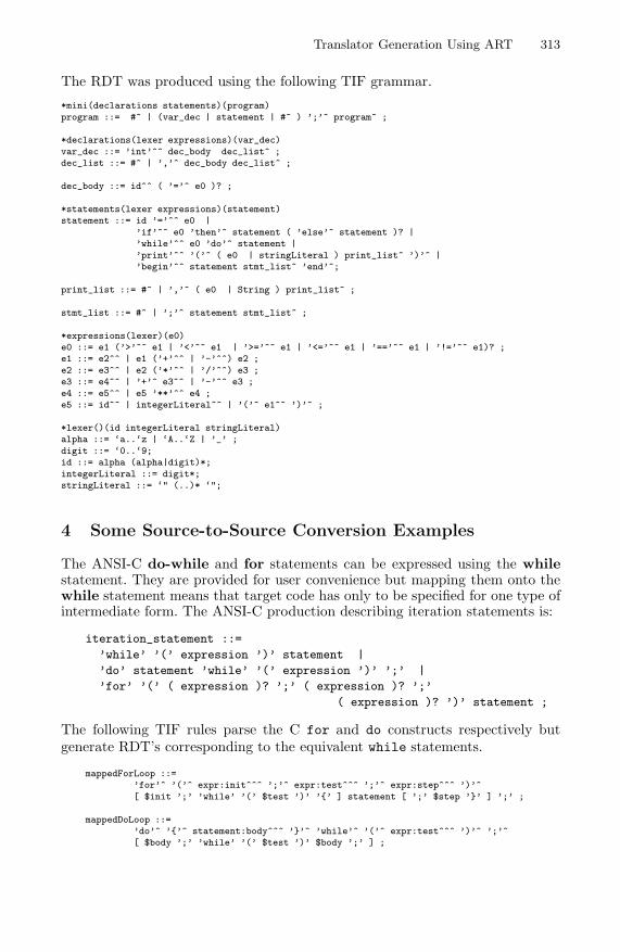
Translator Generation Using ART 313
The RDT was produced using the following TIF grammar.
*mini(declarations statements)(program)program ::= #^ | (var_dec | statement | #^ ) ’;’^ program^ ;
*declarations(lexer expressions)(var_dec)var_dec ::= ’int’^^ dec_body dec_list^ ;dec_list ::= #^ | ’,’^ dec_body dec_list^ ;
dec_body ::= id^^ ( ’=’^ e0 )? ;
*statements(lexer expressions)(statement)statement ::= id ’=’^^ e0 |
’if’^^ e0 ’then’^ statement ( ’else’^ statement )? |’while’^^ e0 ’do’^ statement |’print’^^ ’(’^ ( e0 | stringLiteral ) print_list^ ’)’^ |’begin’^^ statement stmt_list^ ’end’^;
print_list ::= #^ | ’,’^ ( e0 | String ) print_list^ ;
stmt_list ::= #^ | ’;’^ statement stmt_list^ ;
*expressions(lexer)(e0)e0 ::= e1 (’>’^^ e1 | ’<’^^ e1 | ’>=’^^ e1 | ’<=’^^ e1 | ’==’^^ e1 | ’!=’^^ e1)? ;e1 ::= e2^^ | e1 (’+’^^ | ’-’^^) e2 ;e2 ::= e3^^ | e2 (’*’^^ | ’/’^^) e3 ;e3 ::= e4^^ | ’+’^ e3^^ | ’-’^^ e3 ;e4 ::= e5^^ | e5 ’**’^^ e4 ;e5 ::= id^^ | integerLiteral^^ | ’(’^ e1^^ ’)’^ ;
*lexer()(id integerLiteral stringLiteral)alpha ::= ‘a..‘z | ‘A..‘Z | ’_’ ;digit ::= ‘0..‘9;id ::= alpha (alpha|digit)*;integerLiteral ::= digit*;stringLiteral ::= ‘" (..)* ‘";
4 Some Source-to-Source Conversion Examples
The ANSI-C do-while and for statements can be expressed using the whilestatement. They are provided for user convenience but mapping them onto thewhile statement means that target code has only to be specified for one type ofintermediate form. The ANSI-C production describing iteration statements is:
iteration_statement ::=
’while’ ’(’ expression ’)’ statement |
’do’ statement ’while’ ’(’ expression ’)’ ’;’ |
’for’ ’(’ ( expression )? ’;’ ( expression )? ’;’
( expression )? ’)’ statement ;
The following TIF rules parse the C for and do constructs respectively butgenerate RDT’s corresponding to the equivalent while statements.
mappedForLoop ::=’for’^ ’(’^ expr:init^^^ ’;’^ expr:test^^^ ’;’^ expr:step^^^ ’)’^[ $init ’;’ ’while’ ’(’ $test ’)’ ’{’ ] statement [ ’;’ $step ’}’ ] ’;’ ;
mappedDoLoop ::=’do’^ ’{’^ statement:body^^^ ’}’^ ’while’^ ’(’^ expr:test^^^ ’)’^ ’;’^[ $body ’;’ ’while’ ’(’ $test ’)’ $body ’;’ ] ;

314 A. Johnstone and E. Scott
We can also use TIF annotations to generate a uniform intermediate form fromrestricted cases of generic constructs. The following TIF rules generate an RDTfrom a for loop which has a root node labelled for and exactly four children,three of them valid expression sub-trees and one an instance of statement.
expressionFriendlyForLoop ::=
’for’^^ ’(’ Eexpr ’;’ Eexpr’;’ Eexpr ’)’ statement ;
Eexpr ::= expression^^ | # [’true’^^] ;
Empty expressions are remapped so that if the programmer chooses to omit oneof the control expressions we insert the expression true instead of leaving a childlabelled with the epsilon symbol (or indeed no child at all by some conventions).We choose true because the C semantics for for specifies that the default forthe step expression is that loop execution continues forever. C always discardsthe result of the initialisation and step expressions; only the side effects are used.Hence any side-effect free expression is a valid default.
5 Concluding Remarks and Open Issues
ART is fast, powerful and unfinished. There are a variety of open issues thatwe are experimenting with, and we expect to modify the tool’s behaviour inresponse to user experiences.
At present, ART directly implements EBNF parentheses and the ? operatorby multiplying out. Closures are handled by the auxiliary gramconv tool. As aresult, ART only need generate parser templates for BNF grammars. We havedeveloped parser templates for EBNF constructs which allow iteration withinthe GLL parser to directly and efficiently handle closures, but the exact form ofthe trees to be produced is the subject of further study: it is not clear for instancewhether a Kleene closure matching the empty string should yield a node labelledε in the SPPF or simply be suppressed.
We have syntax to support lexical level rules, but the exact form of thelexer/parser divide is not specified. ART can produce GLL parsers which trulyrun at the character level, but the resulting SPPF’s can be very large. Alterna-tively, ART can interface to DFA style lexers.
The fold operators in the TIF formalism are inspired by RDP’s fold operators.RDP has been used in a wide variety of industrial and research projects over thelast 15 years, and we have confidence that the basic notions of folding are usefuland comfortable for engineers. In detail, ART’s folds work differently in the casewhere we have chains of fold operators, that is when we fold a rule which also hasfolds on its own right hand side. In RDP, a fold-under operator could promotea fold over operator which then reached up and over the original parent node.We have outlawed this behaviour in ART by ensuring that fold under operatorstake priority over fold overs. Interestingly, we have never found an instance ofthis construct in any real RDP grammar.
ART can perform insertions of nonterminals which generate singleton lan-guages, that is languages with only one string. ART builds the derivation tree

Translator Generation Using ART 315
for that single sentence, and inserts it. In the TIF formalism as described in [3]an insertion may be made of a (N, s) pair in which the derivation of string s inthe grammar whose start symbol is N is inserted. ART’s present limitation tosingleton languages is a restricted version of this: we intend to implement thefull semantics in a future version.
Finally, we note the lack of change management capability we need to designa TIF metalanguage which described the annotations to be applied: this couldthen be interpreted by ART as part of the generation of Γi.
References
1. Bravenboer, M., Kalleberg, K.T., Vermaas, R., Visser, E.: Stratego/xt 0.17. a lan-guage and toolset for program transformation. Sci. Comput. Program. 72(1-2), 52–70(2008)
2. Johnstone, A., Scott, E.: GLL parsing. In: Proc. 9th Workshop on Language De-scriptions, Tools and Applications LDTA 2009 (2009)
3. Johnstone, A., Scott, E.: Tear-Insert-Fold grammars. In: LDTA 2010 Tenth Work-shop on Language Descriptions, Tools and Applications (2010)
4. McPeak, S., Necula, G.C.: Elkhound: A fast, practical GLR parser generator. In:Duesterwald, E. (ed.) CC 2004. LNCS, vol. 2985, pp. 73–88. Springer, Heidelberg(2004)
5. Necula, G.C., McPeak, S., Rahul, S.P., Weimer, W.: CIL: Intermediate language andtools for analysis and transformation of C programs. In: CC 2002. LNCS, vol. 2304,pp. 213–228. Springer, Heidelberg (2002)
6. van den Brand, M.G.J., Heering, J., Klint, P., Olivier, P.A.: Compiling languagedefinitions: the ASF+SDF compiler. ACM Transactions on Programming Languagesand Systems 24(4), 334–368 (2002)
7. van den Brand, M.G.J., Heering, J., Klint, P., Olivier, P.A.: Compiling languagedefinitions: the ASF+SDF compiler. ACM Transactions on Programming Languagesand Systems 24(4), 334–368 (2002)

Empirical Language Analysis in Software Linguistics
Jean-Marie Favre1, Dragan Gasevic2, Ralf Lammel3, and Ekaterina Pek3
1 OneTree Technologies, Luxembourg2 Athabasca University, Canada
3 Universitat Koblenz-Landau, Germany
Abstract. Software linguistics is the science of software languages. In this shortpaper, we sketch the general discipline of software linguistics, but our focus ison one part of it: empirical analysis of software languages. Such analysis is con-cerned with understanding language usage on the grounds of a corpus. In thisshort paper, we sketch a survey on empirical language analysis, and we arguethat the research method of content analysis is needed for a thorough survey.
1 Introduction
Software Language Engineering (SLE) or “Software Languages are Software too”.Software language descriptions and processors are pieces of software. Hence, all kindsof Software Engineering concepts and techniques can be adopted to software languages.SLE is about the systematic design, implementation, deployment, and evolution of soft-ware languages [14]. Clearly, software language descriptions have particular properties,when compared to other kinds of artifacts in software engineering. Hence, traditionalsoftware engineering life-cycles, methods, set of qualities and constraints must be gen-uinely adapted. If we think about the distinction of software languages vs. natural lan-guages, then Software Language Engineering can be compared to the established fieldof Natural Language Engineering [6,10].
Software Linguistics (SL) or “Software Languages are Language too”. SLE prac-tices should be informed by scientific knowledge. In the case of natural languages,linguistics is the science of languages [5]. Hence, it is worth to see which concepts,research methods, perhaps even techniques or results from the field of linguistics couldbe adopted to the study of software languages. In this manner, we obtain “Software Lin-guistics”. The term Software Linguistics was introduced by Misek-Falkoff in 1982 [18].This term and the whole concept of adopting linguistics for software (programming)languages has not seen much interest. We refer to [8,17] for some controversy. We notethat Software Linguistics should not be confused with Computational Linguistics—theformer is “linguistics for software languages”; the latter is (simply speaking) “comput-ing for linguistics” (for natural languages).
Towards a survey on empirical software language analysis. A common form ofsoftware linguistics is empirical analysis of software language where one is concernedwith understanding usage of software languages on the grounds of a corpus. We areinterested in any kind of software language. Such analysis has been carried out for
B. Malloy, S. Staab, and M. van den Brand (Eds.): SLE 2010, LNCS 6563, pp. 316–326, 2011.c© Springer-Verlag Berlin Heidelberg 2011

Empirical Language Analysis in Software Linguistics 317
many software languages and many aspects of language usage. In this short paper, webegin a corresponding survey of a collection of publications on the subject of empiri-cal software language analysis. This is work in progress, and we discuss how we ex-pect to use the research method of content analysis [15] for the continuation of theproject.1
Road-map. In Sec. 2, we contextualize the present paper in reference to linguistics fornatural and software languages. In Sec. 3, we begin the survey of a collection of paperson empirical language analysis. In Sec. 4, we discuss the employment of the researchmethod of content analysis for completing the current efforts on surveying empiricallanguage analysis in a systematic manner. In Sec. 5, we conclude the paper.
2 Broader Research Context: Software LinguisticsEmpirical software language analysis is an important part of Software Linguistics. Asurvey on such work helps understanding and improving the state of the art in empiricalsoftware language analysis—also specifically with regard to scientific methodology.Such a surveying effort also exercises the adoption of regular linguistics to software.
In this section, we would like to contribute to a broader understanding and definitionof Software Linguistics—through references to (Natural) Linguistics. We have foundthat the mature, scientific framework provided by linguistics can be reused for soft-ware languages—even though many techniques related to natural languages may notbe (directly) applicable. Much can be reused beyond the classical separation of dif-ferent levels such as syntax, semantics and pragmatics. In fact, one can systematicallymine Software Linguistics from resources such as “The Cambridge encyclopedia oflanguage” [5]. A few examples are given below.
Comparative linguistics studies, compares and classifies languages according to theirfeatures using either a quantitative or qualitative approach. It aims at identifying pat-terns that are recurrent in different languages, but also differences and relationshipsbetween languages. Comparative linguistics may also apply to software languages. Forinstance, “Programming Linguistics” [7] compares programming languages in termsof commonalities, relationships, and differences while discussing basic matters of syn-tax, semantics and styles. “The comparison of programming languages: A linguisticapproach” [12] goes deeper into linguistic aspects. We also refer to [2,19].
Historical linguistics studies the history and evolution of languages—often with thegoal of identifying language families, that is, languages that derive from a commonancestor. Part of this research compensates for the lost origin of natural languages. Inthe case of software languages, history is often well documented. Consider, for exam-ple, the History of Programming Languages (HOPL) conference series. HOPL focuseson programming languages rather than software languages in general. Also, HOPL does
1 There is the SourceForge project http://toknow.sourceforge.net/ that is desig-nated to this surveying effort on empirical analysis of software languages. The project hosts(identifies) a paper collection, in particular. In the present paper, references to the papers of thecollection use angle brackets as in “〈Knuth71〉”.

318 J.-M. Favre et al.
not stipulate systematic linguistics studies; a typical paper relies on historical accountsby the primary language designers. Some reports, though, provide a large set of quali-tative information regarding the evolution of dialects of languages, e.g., [1]. The impactof the evolution of software languages on software evolution, though real, is not wellunderstood [9], and deserves more research inspired by linguistics.
Geo-linguistics studies the intersection of geography and linguistics. Studies can, forexample, take into account the distribution of languages or dialects over countries, con-tinents, and regions. We encounter a related “clustering” dimension for software lan-guages in Sec. 3. Also, in [19], the emergence of dialects of Lisp are considered interms of geographical zones.
Socio-linguistics studies languages as social and societal phenomena. The design ofsoftware languages and dialects is often directly linked to such phenomena, too. Forinstance, in [19] Steele and Gabriel conclude “Overall, the evolution of Lisp has beenguided more by institutional rivalry, one-upsmanship, and the glee born of technicalcleverness that is characteristic of the hacker culture than by sober assessments of tech-nical requirements”. The field of socio-linguistics for software remains largely unex-plored, but see [3] for a related account.
Corpus linguistics deals with all aspects of designing, producing, annotating, ana-lyzing and sharing corpora. Producing a useful, natural linguistics corpus could be aneffort that goes far beyond what individual researchers or teams can do. There are in-ternational associations who support sharing, e.g., the European Language ResourcesAssociation (ELRA).2 One should assume that empirical research on the usage of soft-ware languages also involves efforts on ‘software corpus engineering/linguistics’. Suchsoftware corpus linguistics should be simplified by the fact that software language arti-facts are inherently digitally stored. However, the survey of Sec. 3 shows that corporaare too often unavailable or unreproducible.
3 Towards a Survey on Empirical Language Analysis
In the following, we describe the beginning of a survey on empirical language analy-sis. In particular, we identify first research questions, and we provide a correspondingcoding scheme a la content analysis [15].
3.1 Paper Collection
At the time of writing, we have accumulated 52 papers on empirical analysis of soft-ware languages. As an illustration, Fig. 1 shows the language distribution for the fullcollection. For reasons of brevity and maturity of all metadata, all of the subsequenttables will focus on a selective collection of 17 papers. Both the full and the selectivecollections are described online; see footnote 1.
2 ELRA website: http://www.elra.info/

Empirical Language Analysis in Software Linguistics 319
Fig. 1. Tag cloud for the language distribution for the underlying paper collection
3.2 Research Questions
i) Each paper in the collection involves a corpus of a chosen software language. Whatare the characteristics of those corpora; refer to Sec. 3.4? ii) Each empirical analysiscan be expected to serve some objective. What are those objectives for the collectionof papers; refer to Sec. 3.5? iii) Each empirical analysis can be expected to leveragesome actual (typically automated) analyses on the corpus. What are those analyses forthe collection of papers; refer to Sec. 3.6?
3.3 Terminology
We use the term (software) corpus to refer to a collection of items that are expressed inthe language at hand. (These items may be valid or invalid elements of the language in aformal sense.) Items originate from possibly several sources. We use the term source torefer to different kinds of physical or virtual sources that contribute items. For instance,a corpus may leverage an open-source repository as a source to make available, orto retrieve the items—based on an appropriate search strategy. A paper may providea corpus description that identifies sources and explains the derivation of the actualcorpus (say, item set) from the sources.
3.4 Corpus Characteristics
Fig. 2 provides metadata that we inferred for the corpora of the selective paper col-lection.3 We capture the following characteristics of the software corpora: the softwarelanguage of the corpus, numbers of sources and items (with a suitable unit), the onlineaccessibility of the sources (on a scale of none, partial, and full), and the reproducibil-ity of the corpus (on a scale of none, approximate, precise, and trivial). We say thatreproducibility is trivial, if the corpus is available online—in one piece; reproducibil-ity is precise, if the sources and the corpus description suffice to reproduce the corpusprecisely by essentially executing the corpus description. Otherwise, we apply a judge-ment call, and use the tags approximate or none. For instance, the inability to reproducea ranking list of a past web search may be compensated for by a new web search, andhence, reproducibility can be retained at an approximate level. In future work, we wouldlike to go beyond the characteristics that we have sketched here.
3 A cell with content “?” means that the relevant data could not be determined.

320 J.-M. Favre et al.
language sources items unit accessibility reproducibility〈AlvesV05〉 SDF 8 27 grammars partial approximate〈BaxterFNRSVMT06〉 Java 17 56 projects full precise〈ChevanceH78〉 COBOL 1 50 programs none none〈CollbergMS04〉 Java 1 1132 JAR files full approximate〈CookL82〉 Pascal 1 264 programs none none〈CranorESMC08〉 P3P 3 ? policies full approximate〈GilM05〉 Java 4 14 projects full precise〈HageK08〉 Haskell 1 68000 compilations none approximate〈Hahsler04〉 Java 1 988 projects full approximate〈Hautus02〉 Java ? 9 packages full approximate〈KimSNM05〉 Java 2 2 programs full approximate〈Knuth71〉 Fortran 7 440 programs none none〈LaemmelKR05〉 XSD 2 63 schemas partial none〈LaemmelP10〉 P3P 1 3227 policies full trivial〈ReayDM09〉 P3P 1 2287 policies full approximate〈SaalW77〉 APL 6 32 workspaces none none〈Visser06〉 XSD 9 9 schemas full approximate
Fig. 2. Corpus characteristics for selective paper collection
3.5 Objectives of the Papers
Based on our (preliminary) analysis of the paper collection, we propose the following(preliminary) list of objectives for empirical language analysis; see Fig. 3 for corre-sponding metadata for the selective paper collection.
Language adoption. The objective is to determine whether the language is used, andwith what frequency. Typically, some scope applies. For instance, we may limit thescope geographically, or on the time-line.
Language habits. The objective is to understand the usage of the language in terms ofsyntactically or semantically defined terms. For instance, we may study the coverageof the language’s diverse constructs, or any other, well-defined metrics for that matter.This objective may be addressed with substantial measurements and statistical analysis.
Language taming. The objective is to impose extra structure on language usage so thathabits can be categorized in new ways. For instance, we may equip the language withpatterns or metrics that are newly introduced or adopted from other languages. In somecases, the empirical effort towards addressing the objective of language taming mayalso qualify as effort that attests to the objective of language habits.
User feedback. The objective is to compile data of any kind that helps the language userto better understand or improve programs. For instance, we may carry out an analysisto support the proposal of a new pattern that should help with using the language moreeffectively. This objective could be seen as a more specific kind of language taming.

Empirical Language Analysis in Software Linguistics 321
〈Alv
esV
05〉
〈Bax
terF
NR
SVM
T06〉
〈Che
vanc
eH78〉
〈Col
lber
gMS0
4〉〈C
ookL
82〉
〈Cra
norE
SMC
08〉
〈GilM
05〉
〈Hag
eK08〉
〈Hah
sler
04〉
〈Hau
tus0
2〉〈K
imSN
M05〉
〈Knu
th71〉
〈Lae
mm
elK
R05〉
〈Lae
mm
elP1
0〉〈R
eayD
M09〉
〈Saa
lW77〉
〈Vis
ser0
6〉
language adoption • • •language habits • • • • • • • •language taming • • • • • •user feedback •language evolution • •user behavior •implementor feedback • • • •
Fig. 3. Objectives of the selected publications
Language evolution. The objective is to gather input for design work on the nextversion of the language. For instance, we may try to detect indications for missingconstructs.
User behavior. The objective is to understand the usage of the language and its toolsin a way that involves users or user experiences directly—thereby going beyond thenarrow notion of corpus consisting only of “programs”. For instance, we may anal-yse instances of compiler invocations with regard to problems of getting programs tocompile eventually.
Implementor feedback. The objective is to understand parameters of language usagethat help language implementors to improve compilers and other language tools. Forinstance, we may carry out an analysis to suggest compiler optimizations.
Without going into detail here, the available data caters for various observations. Forinstance, we realize that research on language adoption is generally not exercised forprogramming languages. It appears that online communications but not scientific pub-lications are concerned with such adoption.4,5,6
3.6 Analyses of the Papers
Based on our (preliminary) analysis of the paper collection, we have come up with asimple hierarchical classification of (typically automated) analyses that are leveragedin the empirical research projects; see Fig. 4 for the classification; see Fig. 5 for corre-sponding metadata for the selective paper collection.
The presented classification focuses on prominent forms of static and dynamic anal-ysis. In our paper collection, static analysis is considerably more common, and there
4 The TIOBE Index of language popularity: http://www.tiobe.com/tpci.htm5 Another web site on language popularity: http://langpop.com/6 Language Popularity Index tool: http://lang-index.sourceforge.net/

322 J.-M. Favre et al.
Static analysis Source code or other static entities are analyzed.Validity The validity of items in terms of syntax or type system is analyzed.Metrics Metrics are analyzed.
Size The size of items is analyzed, e.g., in terms of lines of code.Complexity The complexity of items is analyzed, e.g., the McCabe complexity.Structural properties Example: the depth of inheritance hierarchy in OO programs.
Coverage The coverage of language constructs is analyzed.Styles The usage of coding styles is analyzed.Patterns The usage of patterns, e.g., design patterns, is analyzed.Cloning Cloning across items of the corpus is analyzed.Bugs The items are analyzed w.r.t. bugs that go beyond syntax and type errors.
Dynamic analysis Actual program runs are analyzed.Profiles Execution frequencies of methods, for example, are analyzed.Traces Execution traces of method calls, for example, are analyzed.
Dimensions of analysis Orthogonal dimensions applicable to analyses.Evolution An analysis is carried out comparatively for multiple versions.Clustering The corpus is clustered by metadata such as country, team size, or others.
Fig. 4. Classification of analyses
〈Alv
esV
05〉
〈Bax
terF
NR
SVM
T06〉
〈Che
vanc
eH78〉
〈Col
lber
gMS0
4〉〈C
ookL
82〉
〈Cra
norE
SMC
08〉
〈GilM
05〉
〈Hag
eK08〉
〈Hah
sler
04〉
〈Hau
tus0
2〉〈K
imSN
M05〉
〈Knu
th71〉
〈Lae
mm
elK
R05〉
〈Lae
mm
elP1
0〉〈R
eayD
M09〉
〈Saa
lW77〉
〈Vis
ser0
6〉
validity • • • •metrics • • • • • • • • • • •coverage • • • • • • • • •styles • • • • •patterns • •cloning • •bugs • • •profiles • • •tracesevolution • • •clustering • • •
Fig. 5. Analyses of the selected publications
is a substantial variety of different analyses. We also indicate two additional dimen-sions for analyses. An analysis is concerned with evolution, when different versions ofitems, sources, or languages are considered. The dimension of clustering generalizesgeo-linguistics of Sec. 2. By no means, our classification scheme is complete. For in-stance, we currently miss characteristics regarding data analysis (e.g., in terms of the

Empirical Language Analysis in Software Linguistics 323
involved statistical methods), and the presentation of research results (e.g., in terms ofthe leveraged tables, charts, etc.).
4 Outlook on Research Methodology
The survey is work in progress. We are in the process of assessing the feasibility of sucha survey, discovering research questions, and studying applicable research methodol-ogy. Ultimately, we aim at reproducible research results and assessment of validity andlimitations. In this discussion section, we briefly hint at the utility of content analysisfor the continuation of this research.
4.1 Content vs. Meta-analysis
We consider two research methods commonly used in social and health sciences, namely,content analysis [15] and meta-analysis [11]. Content analysis is a qualitative researchmethod commonly used for systematically studying large amounts of communicationcontent such as news, articles, books, videos, or blogs. The key characteristic is that theanalyzed content is categorized by researchers. Systematic literature surveys [4] oftenleverage content analysis.
Meta-analysis is another research method used for a systematic analysis of researchliterature. Unlike content analysis, meta-analysis is a quantitative method, and it is fo-cused on research studies that have highly related research hypotheses. The main goalof a meta-analysis is to aggregate and statistically analyze findings of several researchstudies. Meta-analysis uses stricter inclusion criteria than content analysis: measuredoutcomes, and sufficient data to calculate effect sizes. These specifics of meta-analysischallenge its application to empirical software engineering [13]. As a result, we focuson content analysis for the ongoing survey.
4.2 Adoption of Content Analysis
Let us synthesize the main steps for applying content analysis for studying literatureon empirical software language engineering; here we follow the advice of [4]. (Contentanalysis could serve as a convenient research method for studying not only researchpublications, but also other types of communications such as online discussions aboutlanguages, news articles, or bug report histories.)
1. Formulate research questions. In Sec. 3, we listed research questions related tocorpus characteristics, objectives and analyses. We may add questions, for example,about i) the correlation between different factors (e.g., languages vs. objectives), ii) theadopted research method, iii) the statistical techniques that are leveraged, and iv) thepresentational tools (figures, charts) etc. that are used in the papers.
2. Formulate inclusion criteria for papers. These criteria are derived from the re-search questions. So far, we have been using these criteria: i) the paper discusses usageof a software language, and ii) the paper reports empirical results on such usage basedon a corpus. These constraints may need to be made more precise to avoid inclusion of“irrelevant” papers.

324 J.-M. Favre et al.
3. Collect data. That is, we need to discover the relevant literature. Our preliminarycollection has been obtained in an ad-hoc manner. We harvested several papers fromthe literature work that went into our prior, related research: 〈LaemmelKR05〉, 〈LaemmelP10〉.We examined first-degree and second-degree references. While searching those paperson the web, we encountered a few more “obvious” candidates.
A systematic approach commences as follows. First, we need to determine thesources from which the papers will be collected. To this end, we may select digitallibraries (e.g., ACM, IEEE, Science Direct, and Springer), and other online sources(DBLP7), where the papers will be searched. Next, we need to define the search strat-egy. In particular, we need methodologically defined keywords including constraints ontheir combination so that the search strategy is reproducible and amenable to assess-ments. Ultimately, the search strategy needs to be executed so that all those papers arecollected that satisfy the inclusion criteria.
4. Evaluate data. The collected data is evaluated in terms of some classification scheme,which is commonly called coding scheme, and which consists of a set of categories thatdescribe the studied domain. In some cases, a (part of a) coding scheme can be definedup-front. For instance, we designed the corpus characteristics of the papers up-front;refer to Sec. 3.4. In general, categories may emerge during evaluation. For instance,we perceived the objectives for empirical language analysis only post-priori; refer toSec. 3.5. There is a systematic process for developing a coding scheme based on theiteration of certain steps of discovery and testing by other researchers [20].
Each paper in the collection has to be coded eventually. Coding is typically done bytwo researchers (so-called raters) independently. Two authors of the present paper haveacted as raters in some limited manner. For a proper execution, it is inevitable to keeptrack of original codes of the researchers and the reconciled ones. This is needed for thecomputation of a measure of accuracy of the coding scheme.
As the process of data collection and coding might be rather labor-intensive, contentanalysis may leverage some more automated approaches. For example, text mining isone possible approach [16], and off-the-shelf tools—such as AeroText and SPSS—provide corresponding support. It will be interesting to see how well text mining worksin our domain.
5. Analyse data. Frequencies of each category are to be calculated and reported. Thefrequencies describe the level of coverage of a certain phenomenon of interest studiedin the domain. As these frequencies are obtained through a systematic research process,they can nicely reflect on the main types of problems the research has been focused on,and probably discover some patterns about missing research. Such analysis also helpsgiving relatively objective answers to the research questions.
6. Publish analysis. The publication must describe all methodological steps, and in-clude all data needed for reproducibility. For instance, inclusion of the discovered num-ber of papers (per used source), and included papers are mandatory. Similarly, detailsof data evaluation and data analysis need to be included. For instance, measures of
7 http://www.informatik.uni-trier.de/˜ley/db/

Empirical Language Analysis in Software Linguistics 325
accuracy of the coding scheme are to be included. Further, a qualitative discussion ofthe surveyed papers must be provided.
5 Concluding Remarks
We have described the beginning of a literature survey on empirical language analysis.We have presented first results of the emerging survey and discussed details of theunderlying research method. We hope to get other software language engineers andempirical software engineers as well as software linguists or even classical linguistsinvolved in this effort.
In the work on the survey, so far, we have found it inspirational to consult lin-guistics (for natural languages). In particular, linguistics provides input for the cate-gorization needed in the survey, and it suggests underrepresented areas of empiricallanguage analysis. The other interesting insight has been that a survey on empirical lan-guage analysis, in itself, also calls for an empirical method, and we have found thatcontent analysis provides a good fit to produce a first survey on empirical languageanalysis.
References
1. Barbara, M.B., Ryder, G., Soffa, M.L.: The impact of software engineering research onmodern progamming languages. ACM Transactions on Software Engineering and Method-ology 14(4), 431–477 (2005)
2. Baron, N.S.: How to Make Your Way through the New Language Maze - Computer Lan-guages: a Guide For The Perplexed. Doubleday (1986)
3. Bertil Ekdahl, L.J.: The difficulty in communicating with computers. In: Interactive Conver-gence: Critical Issues in Multimedia, ch. 2. Inter-Disciplinary Press (2005)
4. Cooper, H.M.: The integrative research review: A systematic approach. Applied social re-search methods series, vol. 2. Sage, Thousand Oaks (1984)
5. Crystal, D.: The Cambridge Encyclopedia of Language, 2nd edn. Cambridge UniversityPress, Cambridge (2005)
6. Cunningham, H.: A definition and short history of language engineering. Journal of NaturalLanguage Engineering 5, 1–16 (1999)
7. David Gelernter, S.J.: Programming Linguistics. MIT Press, Cambridge (1990)8. Dijkstra, E.W.: On the foolishness of ”natural language programming”. In: Program Con-
struction, International Summer Schoo, London, UK, pp. 51–53. Springer, Heidelberg (1979)9. Favre, J.-M.: Languages evolve too! changing the software time scale. In: IEEE (ed.) 8th
Interntational Workshop on Principles of Software Evolution, IWPSE (September 2005)10. Georgiev, H.: Language Engineering. Continuum (2007)11. Glass, G.V., McGaw, B., Smith, M.L.: Meta-analysis in social research. Sage, Beverly Hills
(1981)12. Goodenough, J.: The comparison of programming languages: A linguistic approach. In:
ACM/CSC-ER (1968)13. Kitchenham, B., Al-Khilidar, H., Babar, M.A., Berry, M., Cox, K., Keung, J., Kurniawati,
F., Staples, M., Zhang, H., Zhu, L.: Evaluating guidelines for reporting empirical softwareengineering studies. Empirical Software Engineering 13(1), 97–121 (2008)
14. Kleppe, A.: Software Language Engineering: Creating Domain-Specific Languages UsingMetamodels. Addison-Wesley Professional, Reading (2008)

326 J.-M. Favre et al.
15. Krippendorff, K.: Content Analysis: an Introduction to Its Methodology, 2nd edn. Sage,Thousand Oaks (2004)
16. Leech, N.L., Onwuegbuzie, A.J.: Qualitative data analysis: A compendium of techniques anda framework for selection for school psychology research and beyond. School PsychologyQuarterly 23(4), 587–604 (2008)
17. Mahoney, M.: HOPL II - closing panel: The history of programming: Does our present pasthave a future? ACM SIGPLAN Notices 31(11), 15–37 (1996)
18. Misek-Falkoff, L.D.: The new field of ”software linguistics”: An early-bird view. In: ACM(ed.) ACM SIGMETRICS Workshop on Software Metrics (1982)
19. Steele Jr., G.L., Gabriel, R.P.: The evolution of Lisp. ACM SIGPLAN Notices, 231–270(1993)
20. Taylor-Powell, E., Renner, M.: Analyzing qualitative data. In: Evaluation in Social Work:The Art and Science of Practice, ch. 13, University of Wisconsin Extension Program, Devel-opment and Evaluation Unit (2003)

Interactive Disambiguation of MetaPrograms with Concrete Object Syntax
Lennart C.L. Kats1, Karl T. Kalleberg2, and Eelco Visser1
1Software Engineering Research Group, Delft University of Technology, The [email protected], [email protected]
2KolibriFX, Oslo, [email protected]
Abstract. In meta-programming with concrete object syntax, meta programs canbe written using the concrete syntax of manipulated programs. Quotations of con-crete syntax fragments and anti-quotations for meta-level expressions and vari-ables are used to manipulate the abstract representation of programs. These small,isolated fragments are often ambiguous and must be explicitly disambiguatedwith quotation tags or types, using names from the non-terminals of the objectlanguage syntax. Discoverability of these names has been an open issue, as theydepend on the (grammar) implementation and are not part of the concrete syn-tax of a language. Based on advances in interactive development environments,we introduce interactive disambiguation to address this issue, providing real-timefeedback and proposing quick fixes in case of ambiguities.
1 Introduction
Meta programs analyze, transform, and generate programs. Examples include compil-ers, interpreters, and static analysis tools. Most frequently, meta programs operate onthe abstract syntax of an object language, using a structured representation of programsrather than a textual representation of their source code. Using a structured representa-tion ensures well-formedness, enables compositionality of transformations, and makesit easier to support type safety and hygiene. However, manipulating the abstract syntaxthrough an API can get tedious, and larger structures are often hard to recognize.
Meta-programming with concrete object syntax [15] as a surface syntax for the ab-stract representation is, for a great number of situations, a best of both worlds betweena textual and an abstract syntax representation: the meta program is written using thefamiliar concrete syntax of the object language, while at the meta level, all operationsare done on a structured representation of the object program. Concrete object syntaxcan be syntactically checked as meta programs are compiled. This technique is nowsupported by many meta-programming systems [2,3,4,7,12].
A prevailing problem with embedding concrete object syntax inside a meta-languageis that the syntax of the combined meta-and-object language is usually highly ambigu-ous when the embedding employs a single pair of quotation and anti-quotation symbols.For example, a quoted Java code fragment |[ i = 2 ]| can either be an assignmentexpression, part of a local variable declaration, or even an annotation element initializer.
Two approaches have been proposed to address ambiguity in meta programs, eachwith their own trade offs and limitations. Perhaps the most straightforward approach
B. Malloy, S. Staab, and M. van den Brand (Eds.): SLE 2010, LNCS 6563, pp. 327–336, 2011.c© Springer-Verlag Berlin Heidelberg 2011

328 L.C.L. Kats, K.T. Kalleberg, and E. Visser
Fig. 1. Screenshot of a quick fix dropdown menu, listing three possible tags to disambiguate aJava quotation. The menu can be triggered by clicking on the error icon shown in the left margin,or by using a keyboard shortcut. Selecting a suggestion fixes the ambiguity.
is to use tagged quotation and anti-quotation symbols, e.g. writing Expr |[ i = 2 ]|using the tag Expr to indicate that the quotation contains an expression. The otherapproach is to use type information of the meta-programming language to attempt toselect the intended interpretation of a concrete syntax quotation [5,13]. For example,for an embedding of Java in Java, a statement Expr assign = |[ i = 2 ]|; can bedisambiguated based on the declared type Expr, while the quotation itself does not haveto be explicitly tagged.
A pressing problem that both approaches share is a lack of discoverability of quota-tion tags and types. Meta-programmers may be intimately familiar with the concretesyntax of a language, but may not be well-grounded in the specific names of non-terminals in the syntax definition and the corresponding tag and type names. Havingto know these names adds to the learning curve of meta-programming. Furthermore, asobject languages evolve, or as additional object languages are added to a meta program,new ambiguities can be introduced for existing code that has not yet, or insufficiently,been explicitly disambiguated. Neither of the two approaches provides developers withadequate feedback if the developer must decide how to fix such an ambiguity.
In this paper we propose interactive disambiguation as a complementary approach totag-based and type-based disambiguation that addresses the concern of discoverability.Our work builds on advances in interactive development environments (IDEs). ModernIDEs aid in discoverability of language features and APIs by providing features suchas context-aware code completion and quick fixes. Quick fixes provide a facility toquickly fix common errors by selecting a fix from a list of suggestions. In this paper wepropose to use quick fixes to present developers a list of candidate type or tag namesfor ambiguous concrete syntax fragments, allowing them to selectively fix problematicambiguities and quickly discover possible fixes (illustrated in Figure 1). Our interactivedisambiguation approach is fully language independent and does not have to be adaptedfor a specific meta-programming language or its type system.
2 Meta-programming with Concrete Object Syntax
In this section we recapitulate the general method for supporting concrete object syntaxin meta languages and describe the problem of ambiguity. This method, as describedin [15,6], is independent of the meta language used and relies on composition of the

Interactive Disambiguation of Meta Programs with Concrete Object Syntax 329
action-to-java-method:|[ action $[Id:name] {
$[Statement*:s∗]}
]| ->|[ public void $[Id:name]() {
$[Stm*:<statements-to-java> s∗]}
]|
Fig. 2. A rewrite rule that uses concrete object syntax notation to rewrite a WebDSL action to aJava method. s∗ is a meta variable containing a list of statements. name contains an identifier.
syntax of the meta language and the object language. Based on this composition, themeta language can use quotations of object-level code to match and construct codefragments in the object language. In turn, quotations can include anti-quotations thatescape from the object language code in order to include variables or expressions fromthe meta language. As an example, Figure 2 shows a Stratego [4] rewrite rule that usesquotations (indicated by |[...]|) and anti-quotations (indicated by $[...]) to rewrite aWebDSL [16] action definition to a Java method.
Grammar composition. Some meta-programming systems, such as Jak [3] and Meta-AspectJ [8], have been specifically designed for a fixed object language. These systemsuse a carefully handcrafted grammar or parser for the combined meta and object lan-guage. Other systems are more flexible and can be configured for different object lan-guages by combining the grammar for the meta and object languages, and generatinga corresponding parser using a parser generator. Building flexible meta-programmingsystems using traditional parser generators is very difficult, because their grammars arerestricted to LL or LR properties. This means that conflicts arise when the grammar ofthe meta language and the object language are combined [6], and these must be resolvedbefore the meta-and-object language parser can be constructed. A further impedimentto language composition found in traditional parsers is the use of a separate scanner,requiring the use of a single lexical syntax definition for the combined language.
By using a combination of SDF for syntax definition and SGLR for parsing [6,14],any object language can be embedded in any meta language [15]. SGLR supports thefull class of context-free grammars, which is closed under composition. This makesit possible to compose languages simply by combining grammar modules. Mixin gram-mars can combine languages by introducing productions for quotation andanti-quotation of an object language to a meta language. Mixin grammars can be writtenby hand or automatically generated using a tool.
As an example of a mixin grammar, Figure 3 shows an excerpt of a grammar thatembeds Java into the Stratego program transformation language. Quotation productionshave the form q1 osort q2 ->msort and specify that a quotation of object-language non-terminal osort , surrounded by (sequences of) symbols q1 and q2, can be used in placeof meta-language non-terminal msort . We sometimes refer to q1 and q2 collectivelyas the quoting symbols. In most of our examples, q1 is |[ and q2 is ]|, or a variationthereof.
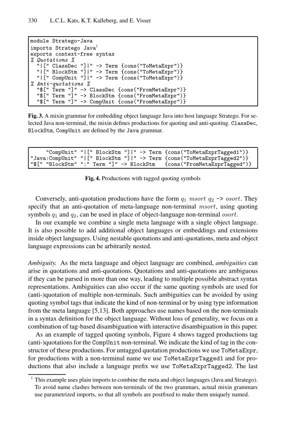
330 L.C.L. Kats, K.T. Kalleberg, and E. Visser
module Stratego-Java
imports Stratego Java1
exports context-free syntax% Quotations %
"|[" ClassDec "]|" -> Term {cons("ToMetaExpr")}"|[" BlockStm "]|" -> Term {cons("ToMetaExpr")}"|[" CompUnit "]|" -> Term {cons("ToMetaExpr")}
% Anti-quotations %"$[" Term "]" -> ClassDec {cons("FromMetaExpr")}"$[" Term "]" -> BlockStm {cons("FromMetaExpr")}"$[" Term "]" -> CompUnit {cons("FromMetaExpr")}
Fig. 3. A mixin grammar for embedding object language Java into host language Stratego. For se-lected Java non-terminal, the mixin defines productions for quoting and anti-quoting. ClassDec,BlockStm, CompUnit are defined by the Java grammar.
"CompUnit" "|[" BlockStm "]|" -> Term {cons("ToMetaExprTagged1")}"Java:CompUnit" "|[" BlockStm "]|" -> Term {cons("ToMetaExprTagged2")}"$[" "BlockStm" ":" Term "]" -> BlockStm {cons("FromMetaExprTagged")}
Fig. 4. Productions with tagged quoting symbols
Conversely, anti-quotation productions have the form q1 msort q2 -> osort . Theyspecify that an anti-quotation of meta-language non-terminal msort , using quotingsymbols q1 and q2, can be used in place of object-language non-terminal osort .
In our example we combine a single meta language with a single object language.It is also possible to add additional object languages or embeddings and extensionsinside object languages. Using nestable quotations and anti-quotations, meta and objectlanguage expressions can be arbitrarily nested.
Ambiguity. As the meta language and object language are combined, ambiguities canarise in quotations and anti-quotations. Quotations and anti-quotations are ambiguousif they can be parsed in more than one way, leading to multiple possible abstract syntaxrepresentations. Ambiguities can also occur if the same quoting symbols are used for(anti-)quotation of multiple non-terminals. Such ambiguities can be avoided by usingquoting symbol tags that indicate the kind of non-terminal or by using type informationfrom the meta language [5,13]. Both approaches use names based on the non-terminalsin a syntax definition for the object language. Without loss of generality, we focus on acombination of tag-based disambiguation with interactive disambiguation in this paper.
As an example of tagged quoting symbols, Figure 4 shows tagged productions tag(anti-)quotations for the CompUnit non-terminal. We indicate the kind of tag in the con-structor of these productions. For untagged quotation productions we use ToMetaExpr,for productions with a non-terminal name we use ToMetaExprTagged1 and for pro-ductions that also include a language prefix we use ToMetaExprTagged2. The last
1 This example uses plain imports to combine the meta and object languages (Java and Stratego).To avoid name clashes between non-terminals of the two grammars, actual mixin grammarsuse parametrized imports, so that all symbols are postfixed to make them uniquely named.

Interactive Disambiguation of Meta Programs with Concrete Object Syntax 331
|[public class X {// ...
}]|
CompUnit |[public class X {
// ...}
]|
|[package org.generated;public class X {// ...
}]|
Fig. 5. Quotations of a Java compilation unit. From left to right: an ambiguous quotation, a quo-tation that is disambiguated by tagging, and a quotation that is already unambiguous withouttagging.
category enables distinction between non-terminals with the same name that are definedin different object languages. For tagged anti-quotations we distinguish FromMetaExprand FromMetaExprTagged.
Figure 5 shows an illustration of both untagged and tagged quotations. The quotationon the left is ambiguous, as it can represent a single class, a class declaration statement,or a compilation unit, each represented differently in the abstract syntax. The quotationin the middle makes it explicit that the intended non-terminal is a compilation unit, re-solving the ambiguity. The quotation on the right is already unambiguous, because onlycomplete Java compilation units can include a package declaration, and does not haveto be explicitly disambiguated. Similar to quotations, anti-quotations can be ambiguousif they can represent multiple possible non-terminals within the context of a quotation.
3 Interactive Disambiguation of Concrete Object Syntax
In this section we describe how ambiguities in concrete object syntax can be inter-actively resolved by analyzing ambiguities and providing quick fix suggestions. Wedescribe different classes of ambiguities and give an algorithm for automatically deter-mining disambiguation suggestions for a given parse forest and grammar.
3.1 Classes of Ambiguities
At the grammar level, there are a number of different classes of ambiguities. In thispaper we focus on ambiguities in quotations and anti-quotations. These ambiguities areinherent to the use of mixin grammars, as languages are woven together and fragmentsmust be parsed with limited syntactic context. Disambiguation with tags or types canresolve these ambiguities. Other forms of ambiguities can be caused by the meta orobject language, such as with the C language that notoriously overloads the * operatorfor multiplication and pointer dereference. Such ambiguities must be retained if they arepart of the object language design, otherwise they should be resolved at the grammarlevel. Ambiguities can also arise by the combination of the two languages if the syntaxbetween the meta and object language overlap. These cannot always be resolved bytype-based disambiguation [13], but can only be avoided by carefully selecting sensiblequoting symbols in such a way that they do not overlap with the meta language andobject language. Ideally, the symbols are chosen to be aesthetically pleasing charactersor character combinations that never occur in either the object or meta language.

332 L.C.L. Kats, K.T. Kalleberg, and E. Visser
ClassDec BlockStm CompUnit
ClassDec PackageDec?ClassDecHead ClassBody ImportDec? TypeDec*
ToMetaExpr ToMetaExpr ToMetaExpr
amb
Fig. 6. The parse forest for the quotation |[ public class X {} ]|
Quotations are ambiguous when they can be parsed in more than one way, accordingto one or more object languages. To illustrate interactive disambiguation suggestionsfor quotations, consider again the untagged quotation in the left-hand side of Figure 5.Recall that this fragment could represent a single class, a class declaration statement,or a compilation unit. Using a generalized parser such as SGLR, the parser constructs aparse forest that branches at the point such an ambiguity, containing all possible subtreesfor the ambiguous expression. Figure 6 illustrates the parse forest for our example, withat the top a special “amb” tree node that has the three possible interpretations as itschildren. The gist of our technique is to analyze the different possible parse trees, andhave the developer select which alternative they intended.
In the mixin grammar for the embedded Java language (shown in Figure 3), thereare three untagged productions that produce the three interpretations of our example.The tagged productions of Figure 4 parse the same object language non-terminal, butinclude distinguishing tags. These tags can be used to disambiguate the example: whenone of the tags ClassDec, BlockStm, or CompUnit is added, there is only one possibleinterpretation of the quotation. By providing quick fix suggestions that automaticallyinsert one of these three tags, meta-programmers can consider the three options anddecide which is the interpretation they intended. In the event that the fragment couldalso be parsed using a different object language that happens to use the same tag names,the prefixed tags such as Java:CompUnit are proposed instead.
Anti-quotations can be disambiguated much like quotations. However, because theyalways occur in the context of a quotation, there is no need for language-prefixed quot-ing tags. For anti-quotations we also distinguish local ambiguity, where a single anti-quotation can be parsed in multiple ways, and non-local ambiguity, where a larger areaof the quotation can be parsed in multiple ways. Non-local ambiguities arise as anti-quotations productions typically reduce to multiple possible non-terminals, whereasquotation productions typically reduce to only one, such as Term in Figure 3.
Figure 7 (left) shows a local ambiguity. The anti-quotation $[x] may be interpretedas an identifier or as the signature of the quoted class. The remainder of the quotation isunambiguous, making it trivial to identify the cause of the ambiguity in the parse forest.
Figure 7 (right) shows a non-local ambiguity. For this example, the entire body of thequotation can be interpreted in multiple ways: it can be either a class y with modifier x,or a package/import/type declaration x followed by a class y. For non-local ambiguitiesit is harder to identify the cause of the ambiguity, as the quotation expressions are nolonger a direct subtree of the “amb” node as they are in Figure 6.

Interactive Disambiguation of Meta Programs with Concrete Object Syntax 333
CompUnit |[class $[x] {// ...
}]|
CompUnit |[$[x] class Y {// ...
}]|
Fig. 7. Example of a local ambiguity (left) and a non-local ambiguity (right). In the first only theanti-quotation $[x] is ambiguous, in the other the entire contents of the quotation is ambiguous.
3.2 Automatic Disambiguation Suggestions
In this subsection we describe an algorithm to automatically collect disambiguation sug-gestions. We implemented the algorithm using Stratego and published the implemen-tation and source code online at [1]. A prototype currently integrates into the Spoofaxlanguage workbench [10].
Figure 8 shows pseudocode for the disambiguation suggestions algorithm. At the top,the CollectSuggestionsTop function is the main entry point, which gets the parseforest and grammar as its input and returns a set of disambiguation suggestions as itsoutput. For each outermost ambiguous subtree amb, it uses the CollectSuggestionsfunction to find local disambiguation suggestions.
The CollectSuggestions function produces a set of disambiguation suggestionsby inspecting each subtree of the amb tree node (line 2). For each branch, it searchesfor the outermost meta-expressions that are not yet completely tagged (line 3). For eachmeta-expression it determines the production prod that was used to parse it (line 4), andits left-hand and right-hand side non-terminals (line 5, 6). For SGLR parse trees, theproduction is encoded directly in the tree node, allowing it to be easily extracted. Onlymeta-expressions that are a direct child of amb (local ambiguities) and meta-expressionsubtrees that do not have any tag (non-local ambiguities) are considered for suggestions(line 7).2 For the selected meta-expressions, a set of possible disambiguation sugges-tions is collected (line 8). These suggestions take the form of tagged meta-expressionproductions (line 9) that contain the same left-hand and right-hand side non-terminalsas the production prod (line 10). Of course, we only include quotation productions ifthe current expression is a quotation, and anti-quotation productions if it is an anti-quotation (line 11). After all corresponding suggestions are collected, the complete setis filtered using the FilterAmbiguousSuggestions function (line 13).
The FilterAmbiguousSuggestions function filters out any suggestions that areambiguous with respect to each other. This is useful if two object languages both matcha meta-expression and they use the same quotation tag X. In those cases, insertingthe tag X would not resolve the ambiguity, and a tag with a language prefix of theform Lang:X must be proposed instead. For suggestions with quoting symbols q1 ,q2(line 3, 4), the function only returns those for which there is no other suggestion withthe same quoting symbols (line 5, 6).
2 A special case is the ToMetaExprTagged1 constructor, used for tagged quotations without alanguage prefix. Suggestions are only provided for local ambiguities with this constructor.

334 L.C.L. Kats, K.T. Kalleberg, and E. Visser
COLLECTSUGGESTIONSTOP(tree, grammar)
1 results ← {}2 foreach outermost subtree amb in tree where amb has the form amb(...)3 results ← results ∪ COLLECTSUGGESTIONS(amb, grammar)4 return results
COLLECTSUGGESTIONS(amb, grammar)
1 results ← {}2 foreach child subtree branch in amb3 foreach outermost subtree expr in amb where ISMETAEXPRTAGGABLE(expr)4 prod ← the production for expr5 lsort ← the non-terminal at left-hand side of prod6 rsort ← the non-terminal at right-hand side of prod7 if expr = branch ∨¬ISMETAEXPRTAGGED(prod) then8 results ← results ∪ { (expr ,prod ′) | prod ′ ∈ productions of grammar9 ∧ ISMETAEXPRTAGGED(prod ′)
10 ∧ prod ′ has the form (q1 lsort q2 -> rsort )11 ∧ prod ′ and prod have the same construc-12 tor prefix To or From }13 return FILTERAMBIGUOUSSUGGESTIONS(results)
ISMETAEXPRTAGGABLE(t)
1 if t has FromMetaExpr, ToMetaExpr, or ToMetaExprTagged1 constructor2 then return true3 else return false
ISMETAEXPRTAGGED(p)
1 if p has FromMetaExprTagged, ToMetaExprTagged1 or ToMetaExprTagged2 constructor2 then return true3 else return false
FILTERAMBIGUOUSSUGGESTIONS(suggestions)
1 return { (prod ,expr ) | (prod ,expr ) ∈ suggestions2 ∧ prod has the form (q1 lsort q2 -> rsort )3 ∧¬∃ (expr ′ ,prod ′) ∈ suggestions :4 prod ′ has the form (q1 lsort ′ q2 -> rsort ′) }
Fig. 8. Pseudo-code for collecting suggested quotation symbols
3.3 Presentation of Suggestions
Interactive disambiguation is based on the notion of quick fixes, small program transfor-mations that can be triggered by the developer in case of a code inconsistency or codesmell. Quick fixes are non-intrusive: as developers write their program, errors or warn-ings are marked inline, but it is up to the developer to decide when and if to address theproblems. For interactive disambiguation, quick fixes allow meta-programmers to writeconcrete syntax for expressions first, allowing the parser to decide whether or not it isambiguous, proposing appropriate quick fixes as necessary.

Interactive Disambiguation of Meta Programs with Concrete Object Syntax 335
The CollectSuggestionsTop function is executed each time the result of parsingthe meta program is ambiguous. The quickfix menu is populated with the results, andany ambiguity can be addressed by adding the tag name or by inserting the type into thecontext of the quotation. In order to avoid spurious suggestions for multiple ambiguities,we only provides suggestions for the outermost expressions (Collect-Suggestions,line 8), allowing meta-programmers to incrementally fix any remaining ambiguities.
While we emphasize interactivity, it should be noted that the technique does notnecessarily require an IDE. Quotation alternatives can also be displayed as part of thebuild process and used with generic text editors that may not interactively parse andanalyze the meta language source code.
In our implementation we cache operations such as collecting productions from thegrammar for efficiency, while in the algorithm described here we abstract from theseoptimizations. Experience with the prototype tells us that the performance overheadof the suggestions algorithm is very low, as it only does a depth-first traversal of eachambiguity and a few hash table lookups.
4 Discussion and Conclusions
In this paper we combined interactive and tag-based disambiguation to reduce quotationnoise in meta-programs with concrete syntax. Developers only need to quote whereabsolutely necessary, and are interactively helped to introduce appropriate quotationsymbols where required.
Interactive disambiguation can also be combined with type-based disambiguation,assisting in cases where type-based disambiguation is inadequate, as multiple type-based interpretations are type correct. These cases particularly arise when combiningthe technique with type inference, as seen with Meta-AspectJ [8], or when forgoingquoting symbols that distinguish between the meta and the object language, as observedby Vinju [13]. Both works propose heuristics as a solution in these cases. Interactive dis-ambiguation can let the programmer interactively, and thus more predictably, resolvesuch ambiguities statically. Alternatively it can assist when programs are not yet typeconsistent, providing suggestions for inserting type declarations or type casts. Strat-ego is largely untyped, ruling out type-based disambiguation for our present prototype.A typed variant of Stratego [11] might be a suitable testbed for experiments combin-ing interactive disambiguation and type inference. On the dynamic side, we have hadpromising experimental results using runtime disambiguation, where the decision ofthe correct interpretation of a meta-expression is delayed until run-time, when the ac-tual values of meta-level expressions are known. Based on a static analysis of the meta-program, it is possible to determine which quotations can safely be disambiguated atruntime.
We performed a preliminary evaluation of our approach using existing source filesthat embed Java in Stratego, from the Dryad Java compiler [9]. The sources use a to-tal of 55 concrete syntax quotations of a wide variety of different Java language con-structs. Most are small quotations, but a few contain complete compilation units, usedfor compilation and for unit testing. We stripped all existing disambiguation tags fromthe sources, and by following the interactive disambiguation suggestions, were able to

336 L.C.L. Kats, K.T. Kalleberg, and E. Visser
successfully disambiguate the files. We then introduced WebDSL [16] as an additionalobject language as a form of an evolution scenario. This introduced new ambiguities, assome expressions such as Expr |[ $[Expr:x] == $[Expr:y] ]| would be a validquotation for either language. Again, applying the quick fixes helped the transition andresolved the ambiguities by introducing language-prefixed tags.
We have found interactive disambiguation to be a practically useful technique, com-plementary approach to both tag-based [6], and type-based disambiguation [5,13], andindependent of the meta and object language and their type system.
Acknowledgements. This research was supported by NWO/JACQUARD projects612.063.512, TFA: Transformations for Abstractions, and 638.001.610, MoDSE:Model-Driven Software Evolution.
References
1. The interactive disambiguation project (2010),http://strategoxt.org/Spoofax/InteractiveDisambiguation
2. Arnoldus, J., Bijpost, J., van den Brand, M.: Repleo: a syntax-safe template engine. In:GPCE, pp. 25–32 (2007)
3. Batory, D., Lofaso, B., Smaragdakis, Y.: JTS: Tools for Implementing Domain-Specific Lan-guages. In: Conference on Software Reuse, p. 143 (1998)
4. Bravenboer, M., Kalleberg, K.T., Vermaas, R., Visser, E.: Stratego/XT 0.17. A language andtoolset for program transformation. SCP 72(1-2), 52–70 (2008)
5. Bravenboer, M., Vermaas, R., Vinju, J.J., Visser, E.: Generalized type-based disambiguationof meta programs with concrete object syntax. In: Gluck, R., Lowry, M. (eds.) GPCE 2005.LNCS, vol. 3676, pp. 157–172. Springer, Heidelberg (2005)
6. Bravenboer, M., Visser, E.: Concrete syntax for objects: domain-specific language embed-ding and assimilation without restrictions. In: OOPSLA, pp. 365–383 (2004)
7. Cordy, J.R., Halpern-Hamu, C.D., Promislow, E.: TXL: A rapid prototyping system for pro-gramming language dialects. Comp. Lang., Syst. & Struct. 16(1), 97–107 (1991)
8. Huang, S.S., Zook, D., Smaragdakis, Y.: Domain-specific languages and program generationwith Meta-AspectJ. Transactions on Software Engineering Methodology 18(2) (2008)
9. Kats, L.C.L., Bravenboer, M., Visser, E.: Mixing source and bytecode: a case for compilationby normalization. In: OOPSLA, pp. 91–108 (2008)
10. Kats, L.C.L., Visser, E.: The Spoofax language workbench. Rules for declarative specifica-tion of languages and IDEs. In: OOPSLA, pp. 444–463 (2010)
11. Lammel, R.: Typed generic traversal with term rewriting strategies. Journal of Logic andAlgebraic Programming 54(1), 1–64 (2003)
12. van Deursen, A., Heering, J., Klint, P. (eds.): Language Prototyping. An Algebraic Specifi-cation Approach. AMAST Series in Computing, vol. 5. World Scientific, Singapore (1996)
13. Vinju, J.J.: Type-driven automatic quotation of concrete object code in meta programs. In:Guelfi, N., Savidis, A. (eds.) RISE 2005. LNCS, vol. 3943, pp. 97–112. Springer, Heidelberg(2006)
14. Visser, E.: Syntax Definition for Language Prototyping. PhD thesis, University of Amster-dam (September 1997)
15. Visser, E.: Meta-programming with concrete object syntax. In: Batory, D., Blum, A., Taha,W. (eds.) GPCE 2002. LNCS, vol. 2487, pp. 299–315. Springer, Heidelberg (2002)
16. Visser, E.: WebDSL: A case study in domain-specific language engineering. In: Lammel,R., Visser, J., Saraiva, J. (eds.) Generative and Transformational Techniques in SoftwareEngineering II. LNCS, vol. 5235, pp. 291–373. Springer, Heidelberg (2008)

Evaluating a Textual Feature Modelling Language:Four Industrial Case Studies
Arnaud Hubaux1, Quentin Boucher1, Herman Hartmann3,Raphael Michel2, and Patrick Heymans1
1 PReCISE Research Centre, Faculty of Computer Science, University of Namur, Belgium{ahu,qbo,phe}@info.fundp.ac.be
2 CETIC Research Centre, [email protected]
3 Virage Logic, High Tech Campus, The [email protected]
Abstract. Feature models are commonly used in software product line engineer-ing as a means to document variability. Since their introduction, feature modelshave been extended and formalised in various ways. The majority of these ex-tensions are variants of the original tree-based graphical notation. But over time,textual dialects have also been proposed. The textual variability language (TVL)was proposed to combine the advantages of both graphical and textual notations.However, its benefits and limitations have not been empirically evaluated up tonow. In this paper, we evaluate TVL with four cases from companies of differ-ent sizes and application domains. The study shows that practitioners can benefitfrom TVL. The participants appreciated the notation, the advantages of a textuallanguage and considered the learning curve to be gentle. The study also revealssome limitations of the current version of TVL.
1 Introduction
Feature models (FMs) were introduced as part of the FODA (Feature Oriented DomainAnalysis) method 20 years ago [1]. They are a graphical notation whose purpose isto document variability, most commonly in the context of software product line engi-neering (PLE) [2]. Since their introduction, FMs have been extended and formalisedin various ways (e.g. [3,4]) and tool support has been progressively developed [5]. Themajority of these extensions are variants of FODA’s original tree-based graphical nota-tion. Figure 1 shows an example of graphical tree-shaped FM that describes the vari-ability of an eVoting component. The and-decomposition of the root feature (Voting)implies that all its sub-features have to be selected in all valid products. Similarly, theor-decomposition of the Encoder feature means that at least one of its child features hasto be selected, and the xor-decomposition of the Default VoteValue feature means thatone and only one child has to be selected. Cardinality-based decompositions can also bedefined, like for VoteValues in the example. In this case, the decomposition type impliesthat at least two, and at most five sub-features of VoteValues have to be selected. Finally,two <requires> constraints impose that the feature corresponding to the default votevalue (Yes or No) is part of the available vote values.
B. Malloy, S. Staab, and M. van den Brand (Eds.): SLE 2010, LNCS 6563, pp. 337–356, 2011.c© Springer-Verlag Berlin Heidelberg 2011
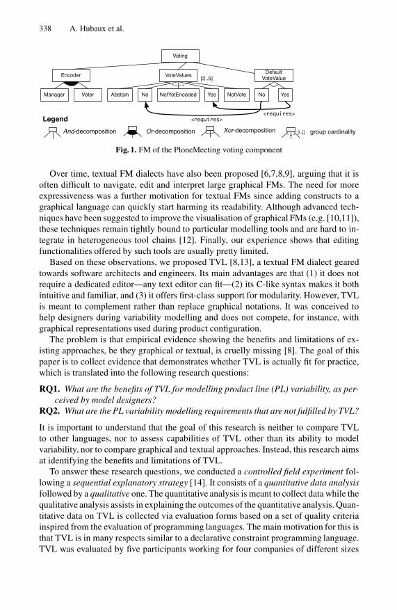
338 A. Hubaux et al.
Voting
Or-decomposition
Legendaa And-decomposition
a Xor-decomposition a group cardinality[i..j]
Encoder VoteValues
NotYetEncoded YesNoAbstain NotVoteManager Voter
[2..5]Default
VoteValue
YesNo
<requires><requires>
Fig. 1. FM of the PloneMeeting voting component
Over time, textual FM dialects have also been proposed [6,7,8,9], arguing that it isoften difficult to navigate, edit and interpret large graphical FMs. The need for moreexpressiveness was a further motivation for textual FMs since adding constructs to agraphical language can quickly start harming its readability. Although advanced tech-niques have been suggested to improve the visualisation of graphical FMs (e.g. [10,11]),these techniques remain tightly bound to particular modelling tools and are hard to in-tegrate in heterogeneous tool chains [12]. Finally, our experience shows that editingfunctionalities offered by such tools are usually pretty limited.
Based on these observations, we proposed TVL [8,13], a textual FM dialect gearedtowards software architects and engineers. Its main advantages are that (1) it does notrequire a dedicated editor—any text editor can fit—(2) its C-like syntax makes it bothintuitive and familiar, and (3) it offers first-class support for modularity. However, TVLis meant to complement rather than replace graphical notations. It was conceived tohelp designers during variability modelling and does not compete, for instance, withgraphical representations used during product configuration.
The problem is that empirical evidence showing the benefits and limitations of ex-isting approaches, be they graphical or textual, is cruelly missing [8]. The goal of thispaper is to collect evidence that demonstrates whether TVL is actually fit for practice,which is translated into the following research questions:
RQ1. What are the benefits of TVL for modelling product line (PL) variability, as per-ceived by model designers?
RQ2. What are the PL variability modelling requirements that are not fulfilled by TVL?
It is important to understand that the goal of this research is neither to compare TVLto other languages, nor to assess capabilities of TVL other than its ability to modelvariability, nor to compare graphical and textual approaches. Instead, this research aimsat identifying the benefits and limitations of TVL.
To answer these research questions, we conducted a controlled field experiment fol-lowing a sequential explanatory strategy [14]. It consists of a quantitative data analysisfollowed by a qualitative one. The quantitative analysis is meant to collect data while thequalitative analysis assists in explaining the outcomes of the quantitative analysis. Quan-titative data on TVL is collected via evaluation forms based on a set of quality criteriainspired from the evaluation of programming languages. The main motivation for this isthat TVL is in many respects similar to a declarative constraint programming language.TVL was evaluated by five participants working for four companies of different sizes
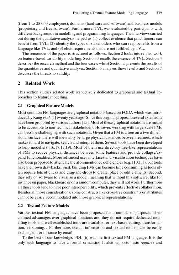
Evaluating a Textual Feature Modelling Language 339
(from 1 to 28 000 employees), domains (hardware and software) and business models(proprietary and free software). Furthermore, TVL was evaluated by participants withdifferent backgrounds in modelling and programming languages. The interviews carriedout during the qualitative analysis helped us (1) collect evidence that practitioners canbenefit from TVL, (2) identify the types of stakeholders who can reap benefits from alanguage like TVL, and (3) elicit requirements that are not fulfilled by TVL.
The remainder of the paper is structured as follows. Section 2 looks into related workon feature-based variability modelling. Section 3 recalls the essence of TVL. Section 4describes the research method and the four cases, whilst Section 5 presents the results ofthe quantitative and qualitative analyses. Section 6 analyses these results and Section 7discusses the threats to validity.
2 Related Work
This section studies related work respectively dedicated to graphical and textual ap-proaches to feature modelling.
2.1 Graphical Feature Models
Most common FM languages are graphical notations based on FODA which was intro-duced by Kang et al. [1] twenty years ago. Since this original proposal, several extensionshave been proposed by various authors [15]. Most of these graphical notations are meantto be accessible to non-technical stakeholders. However, working with large-scale FMscan become challenging with such notations. Given that a FM is a tree on a two dimen-sional surface, there will inevitably be large physical distances between features, whichmakes it hard to navigate, search and interpret them. Several tools have been developedto help modellers [16,17,18,19]. Most of them use directory tree-like representationsof FMs to reduce physical distances between some features and provide collapse/ex-pand functionalities. More advanced user interfaces and visualisation techniques havealso been proposed to attenuate the aforementioned deficiencies (e.g. [10,11]), but toolshave their own drawbacks. First, building FMs can become time consuming as tools of-ten require lots of clicks and drag-and-drops to create, place or edit elements. Second,they rely on software to visualise a model, meaning that without this software, like forinstance on paper, blackboard or on a random computer, they will not work. Furthermoreall those tools tend to have poor interoperability, which prevents effective collaboration.Besides all those considerations, some constructs like cross-tree constraints or attributescannot be easily accommodated into those graphical representations.
2.2 Textual Feature Models
Various textual FM languages have been proposed for a number of purposes. Theirclaimed advantages over graphical notations are: they do not require dedicated mod-elling tools and well-established tools are available for text-based editing, transforma-tion, versioning. . . Furthermore, textual information and textual models can be easilyexchanged, for instance by email.
To the best of our knowledge, FDL [6] was the first textual FM language. It is theonly such language to have a formal semantics. It also supports basic requires and

340 A. Hubaux et al.
excludes constraints and is arguably user friendly, but it does not include attributes,cardinality-based decompositions and other advanced constructs.
The AHEAD [7] and FeatureIDE [18] tools use the GUIDSL syntax [7], where FMsare represented through grammars. The syntax is aimed at the engineer and is thus easyto write, read and understand. However, it does not support decomposition cardinalities,attributes, hierarchical decomposition of FMs and has no formal semantics.
The SXFM file format is used by SPLOT [20] and 4WhatReason [21]. While XMLis used for metadata, FMs are entirely text-based. Its advantage over GUIDSL is thatit makes the tree structure of the FM explicit through indentation. However, except forthe hierarchy, it has the same deficiencies as GUIDSL.
The VSL file format of the CVM framework [22,23] supports many constructs. At-tributes, however, cannot be used in constraints. The Feature Modelling Plugin [16] aswell as the FAMA framework [24] use XML-based file formats to encode FMs. Tagsmake them hard to read and write by engineers. Furthermore, none of them proposes aformal semantics. The Concept Modelling Language (CML) [9] has been recently pro-posed but to the best of our knowledge is still a prototype and is not yet fully defined orimplemented.
3 TVL
Starting from the observation that graphical notations are not always convenient and thatexisting textual notations have limited expressiveness, formality and/or readability, weproposed TVL [8,13], a textual alternative targeted to software architects and engineers.For conciseness, we can only recall here the basic principles of the language. Moredetails about its syntax, semantics and reference implementation can be found in [13].
The following model will be used to illustrate some TVL constructs. It is a translationof the graphical model presented in Figure 1, which is an excerpt of the complete FMwe built for PloneMeeting, one of the case studies. It captures the variability in thevoting system that governs the discussion of meeting items1. Note that the default votevalue is specified here as an attribute rather than a feature.
01 root Voting { // define the root feature
02 enum defaultVoteValue in {yes, no}; //attribute is either yes or no
03 (defaultVoteValue == yes) -> Yes; //yes requires Yes in VoteValues
04 (defaultVoteValue == no) -> No; // no requires No in VoteValues
05 group allOf { // and-decomposition
06 Encoder { group someOf {manager, voter} },07 VoteValues group [2..*] { // <2..5> cardinality
08 Yes,09 No,10 Abstain11 NotYetEncoded,12 NotVote,13 }14 }15 }
1 The complete model is available at http://www.info.fundp.ac.be/˜acs/tvl

Evaluating a Textual Feature Modelling Language 341
TVL can represent FMs that are either trees or directed acyclic graphs. The languagesupports standard decomposition operators [1,3]: or- , xor-, and and-decompositions.For example, the and-decomposition of the Voting is represented from lines 05 to12 (group allOf {...}). The xor-decomposition of the Encoder is representedat line 06 (group oneOf {...}). Generic cardinality-based decompositions [25]can also be defined using a similar syntax (see line 07). Five different types of featureattributes [26] are supported: integer (int), real (real), Boolean (bool), structure(struct) and enumeration (enum). The domain of an attribute can be restricted to apredefined set of values using the in keyword. For instance, the set of available valuesof the enumerated attribute defaultVoteValue is restricted to yes and no (see line02). Attributes can also be assigned fixed or calculated values using the is keyword.Furthermore, the value of an attribute can differ when the containing feature is selected(ifIn: keyword) or not selected (ifOut: keyword). Several standard operators areavailable for calculated attributes (e.g. arithmetic operations). Their value can also becomputed using aggregation functions over lists of attributes. Calculated attributes arenot illustrated in the example.
In TVL, constraints are attached to features. They are Boolean expressions that canbe added to the body of a feature. The same guards as for attributes are available forconstraints. They allow to enable (resp. disable) a constraint depending on the selection(resp. non-selection) of its containing feature. Line 05 is an example of (unguarded)constraint where the assignment of the yes value to the defaultVoteValue at-tribute requires the selection of the Yes feature.
TVL offers several mechanisms to reduce the size of models and modularise them.We only touch upon some of them here and do not illustrate them in the example. First,custom types can be defined and then used in the FM. This allows to factor out recurringtypes. It is also possible to define structured types to group attributes that are logicallylinked. Secondly, TVL supports constants that can be used inside expressions or car-dinalities. Thirdly, include statements can be used to add elements (e.g. features orattributes) defined in an external file anywhere in the code. Modellers can thus struc-ture the FM according to their preferences. The sole restriction is that the hierarchy ofa feature can only be defined at one place (i.e. there is only one group structure foreach feature). Finally, features can have the same name provided they are not siblings.Qualified feature names must be used to reference features whose name is not unique.Relative names like root, this and parent are also available to modellers.
4 Research Method
This section describes the settings of the evaluation, its goals and the four cases alongwith the profiles of the companies and participants involved in the study. The sectionends with a description of the experiment’s protocol.
4.1 Objectives
The overall objective of this paper is to evaluate the ability of TVL to model the vari-ability of a PL as perceived by software engineers. The criteria that we use to measurethe quality of TVL are inspired and adapted from [27,28]. Originally, these criteria were

342 A. Hubaux et al.
defined to evaluate the quality of programming languages. We have selected program-ming language criteria because TVL resembles a declarative constraint programminglanguage whose constructs have been tailored for variability modelling. Finally, TVLshould ultimately be integrated in development environments like eclipse or advancedtext editors like emacs or vim. TVL is thus likely to be assimilated to a programminglanguage by developers. We outline the quality criteria relevant to our study below.
Quality criteria adapted from [27,28].
C1 Clarity of notation The meaning of constructs should be unambiguousand easy to read for non-experts.
C2 Simplicity of notation The number of different concepts should be mini-mum. The rules for their combinations should be assimple and regular as possible.
C3 Conciseness of notation The constructs should not be unnecessarily verbose.
C4 Modularisation The language should support the decompositioninto several modules.
C5 Expressiveness The concepts covered by the language should besufficient to express the problems it addresses.Proper syntactic sugar should also be provided toavoid convoluted expressions.
C6 Ease and cost of model portability The language and tool support should be platformindependent.
C7 Ease and cost of model creation The elaboration of a model should not be overly hu-man resource-expensive.
C8 Ease and cost of model translation The language should be reasonably easy to translateinto other languages/formats.
C9 Learning experience The learning curve of the language should be rea-sonable for the modeller.
No specific hypothesis was made, except that the participants had the appropriate ex-pertise to answer our questions.
4.2 Cases
The evaluation of TVL was carried out with five participants coming from four dis-tinct companies working in different fields (two in computer hardware manufacture,one in meeting management and one in document management). Table 2 summarisesthe profiles of the five participants involved in the evaluation as well as the com-pany and project they work for. For each participant, we indicate his position, yearsof experience in software engineering, his fields of expertise, the modelling and pro-gramming languages he used for the last 5 years, his experience with PLE and FMs,and the number of years he actively worked on the selected project. For the experi-ence with languages, PLE and FMs, we also mention the frequency of use, i.e. inten-sive/regular/casual/evaluation. By evaluation, we mean that the language or concept iscurrently being evaluated in the company. The four cases are described below as wellas the motivations of the participants to use TVL.

Evaluating a Textual Feature Modelling Language 343
Tabl
e2.
Pro
file
sof
the
five
part
icip
ants
Cri
teri
aP
lone
Mee
ting
PR
ISM
Apr
epar
eC
PU
calc
ulat
ion
OSG
ener
ic
Com
pany
Gee
zTee
mO
SLN
amur
S.A
.N
XP
Sem
icon
duct
ors
Vira
geL
ogic
#Em
ploy
ees
170
28
000
(wor
ldw
ide)
700
(wor
ldw
ide)
Loc
atio
nB
elgi
umB
elgi
umT
heN
ethe
rlan
dsT
heN
ethe
rlan
ds
Type
ofso
ftw
are
Ope
nso
urce
Pro
prie
tary
Pro
prie
tary
Pro
prie
tary
Pro
ject
kick
off
date
Janu
ary
2007
May
2008
June
2009
2004
Pro
ject
stag
ere
ache
dP
rodu
ctio
nP
rodu
ctio
nD
evel
opm
ent
Pro
duct
ion
Pro
ject
vers
ion
1.7
buil
d564
4.2
.1Ju
ly6,
2009
Sep
tem
ber
30,2
009
Num
ber
offe
atur
es193
152
19
60
Pos
itio
nF
reel
ance
Pro
duct
Lin
eM
anag
erS
enio
rS
cien
tist
Sen
ior
Sof
twar
eA
rchi
tect
Dev
elop
men
tM
anag
er
Yea
rsof
expe
rien
cein
SE
12+
year
s31
+ye
ars
20+
year
s15
+ye
ars
20+
year
s
Fie
lds
ofex
pert
ise
WA
,CM
SP
MP
M,S
PI,
SR
McS
,RP
C,R
TE
S,R
T
Mod
ellin
gla
ngua
ges
UM
L(r
egul
ar)
Non
eU
ML
(cas
ual)
,D
SC
T(e
valu
atio
n)U
ML
(cas
ual)
UM
L(r
egul
ar)
Pro
gram
min
gla
ngua
ges
Pyt
hon
(int
ensi
ve),
Java
-sc
ript
(reg
ular
)C
++
(cas
ual)
C(c
asua
l),
Pro
log
(reg
u-la
r),J
ava
(eva
luat
ion)
C(i
nten
sive
)C
(cas
ual)
,C
++
(cas
ual)
,V
isua
lB
asic
(cas
ual)
,P
ytho
n(c
asua
l)
Exp
erie
nce
wit
hP
LE
2ye
ars
(eva
luat
ion)
1ye
ar(c
asua
l)3
year
s(i
nten
sive
)4
year
s(r
egul
ar)
4ye
ars
(int
ensi
ve)
Exp
erie
nce
wit
hF
Ds
2ye
ars
(eva
luat
ion)
1ye
ar(c
asua
l)3
year
s(i
nten
sive
)4
year
s(c
asua
l)4
year
s(i
nten
sive
)
Pro
ject
part
icip
atio
n3
year
s2
year
s1
year
6ye
ars
2ye
ars
Leg
end
CM
S-
Con
tent
Man
agem
ent
Sys
tem
,DSC
T-
Dom
ain
Spe
cifi
cC
ompo
nent
sTe
chno
logi
es,E
S-
Em
bedd
edS
yste
m,M
cS-
Mul
ti-c
ore
Sys
tem
,
PM
-P
roje
ctM
anag
emen
t,R
PC
-R
emot
eP
roce
dure
Cal
l,R
T-
Rea
lTim
e,SE
-S
oftw
are
Eng
inee
ring
,SP
I-
Sof
twar
eP
roce
ssIm
prov
emen
t,
SR-
Sof
twar
eR
elia
bili
ty,W
A-
Web
App
lica
tion
s.

344 A. Hubaux et al.
PloneMeeting
Description. PloneGov [29] is an international Open Source (OS) initiative coordi-nating the development of eGovernment web applications. PloneGov gathers hun-dreds of public organizations worldwide. This context yields a significant diversity,which is the source of ubiquitous variability in the applications [30,31,32]. We fo-cus here on PloneMeeting, PloneGov’s meeting management project developed byGeezTeem. PloneMeeting is built on top of Plone, a portal and content managementsystem (CMS) written in Python.
The current version of PloneMeeting extensively uses UML for code genera-tion. However, the developer is not satisfied by the limited editing functionalitiesand flexibility offered by UML tools. To eliminate graphical UML models, he de-veloped appy.gen2. appy.gen allows to encode class and state diagrams, displayparameters, portlet creation, and consistency rules in pure Python and enables theautomated generation of full-blown Plone applications.
PloneMeeting is currently being re-engineered with appy.gen. A major challengeis to extend appy.gen to explicitly capture variation points and provide systematicvariability management. We collaborate with the developer to specify the FM ofPloneMeeting.
Motivation. The initial motivation of the developer to engage in the evaluation was toassess the opportunity of using FMs for code generation. He has not used FMs tothat end so far because, in his words, “graphical editing functionalities (typicallypoint-and-click) offered by feature modelling tools are cumbersome and counter-productive”. The textual representation of FMs is therefore more in line with hisdevelopment practice than their graphical counterpart.
PRISMAprepare
Description. Oce Software Laboratories S.A. (OSL) [33], is a company specializedin document management for professional printers. One of their main PLs is OcePRISMA, a family of products covering the creation, submission and delivery ofprinting jobs. Our collaboration focuses on one sub-line called PRISMAprepare,an all-in-one tool that guides document preparation and whose main features arethe configuration of printing options and the preview of documents.
In the current version of PRISMAprepare, mismatches between the preview andthe actual output can occur, and, in rare cases, documents may not be printable onthe selected printer. The reason is that some incompatibilities between documentoptions and the selected printer can go undetected. For example, a prepared docu-ment can require to staple all sheets together while the target printer cannot staplemore than 20 pages together, or does not support stapling at all. The root cause isthat only some constraints imposed by the printers are implemented in the sourcecode, mostly for time and complexity reasons.
Consequently, OSL decided to enhance its PL by automatically generating con-figuration constraints from printing description files. The objective is twofold: (1)
2 Available online at http://appyframework.org/gen.html

Evaluating a Textual Feature Modelling Language 345
build complete constraint sets and (2) avoid the manual maintenance of cumber-some constraints. So far, we have designed a first FM of the variability of the print-ing properties.
Motivation. Feedback was provided by the product line manager of PRISMAprepare.OSL is currently evaluating different modelling alternatives to express the variabil-ity of its new PL and generate the configuration GUI. The evaluation of TVL is thuspart of their exploratory study of FM languages. Additionally, most of the softwareengineers dealing with FMs are developers, hence their interest for a textual lan-guage.
CPU calculation
Description. NXP Semiconductors [34] is an international provider of IntegratedCircuits (IC). ICs are used in a wide range of applications like automotive, info-tainment and navigation systems. They are the fundamental pieces of hardwarethat enable data processing like video or audio streams. ICs typically embed sev-eral components like CPU, memory, input and output ports, which all impose con-straints on their possible valid combinations.
This study focuses on the FM that models the variability of a video processingunit and study the impact it has on the CPU load. The FM, which is still underdevelopment, is meant to be fed to a software configurator. Thereby, it will sup-port the customer during the selection of features while ensuring that no hardwareconstraint is violated (e.g. excessive clock speed required by the features). TheFM also allows the user to strike an optimal price/performance balance, where theprice/performance ratio is computed from attributes attached to features and moni-tored within the configuration tool.
Motivation. The evaluation was performed by the developer who originally partici-pated in the creation of the FM with a commercial tool, before and independentlyfrom this experiment. Prolog was used for defining the constraints. The major prob-lem is that the time needed to implement the calculation over attributes was deemedexcessive compared to the time needed to design the whole FM. This lead the com-pany to consider TVL as an alternative. Furthermore, the developer’s knowledge ofa declarative language like Prolog motivated him to test a textual constraint mod-elling language.
OSGeneric
Description. Virage Logic [35] is a supplier of configurable hardware and software toa broad variety of customers such as the Dolby Laboratories, Microsoft and AMD.Its variability-intensive products allows its customers to create a specific variant forthe manufacturing of highly tailorable systems on chip (SoC). OSGeneric (Oper-ating System Generic) is a PL of operating systems used on SoCs. The producedoperating systems can include both proprietary and free software. Each SoC canembed a large variety of hardware and contain several processors from differentmanufacturers.

346 A. Hubaux et al.
Motivation. The evaluation was performed by two participants: the lead software ar-chitect of OSGeneric and the software development manager. Their PL is currentlymodelled with a commercial tool. The participants are now considering other vari-ability modelling techniques. Their motivation for evaluating TVL lies in using alanguage that (1) is more suited for engineers with a C/C++ background, (2) hasa lower learning curve than the commercial tool and (3) makes use of standardeditors.
4.3 Experiment Protocol
In this experiment, TVL was evaluated through interviews with the five participants ofthe four companies. Interviews were conducted independently from each other, exceptfor Virage Logic where the two participants were interviewed together. Two researcherswere in charge of the interviews, the synthesis of the results and their analysis. For eachinterview, they followed the protocol presented in Figure 2.
TVL model
1 Introduction to TVL
3 Quantitative evaluation
2 Presentation of TVL model
Evaluation forms
Slides
4 Qualitative evaluation
Document Action Process flow Data flow
Legend
Quality criteriaTVL
documentation
Rationale
Fig. 2. Interview protocol
The protocol starts with a short introduction to TVL (circa 20 minutes) that aims atgiving the participants an overview of the language. At this stage, the participants arenot exposed to details of the language. The goal of the second step is to provide theparticipants with a real TVL model. To keep the effort of the participants moderate,the appointed researchers designed, for each company and prior to the interviews, TVLmodels that respectively correspond to the configuration menus of PloneMeeting andPRIMSAprepare, and the FMs of the CPU calculation and OSGeneric. The presentationof the TVL model was limited to 30 minutes to keep the participants focused on theunderstanding of the model and avoid untimely discussions about the quality of thelanguage. During that step, the participants are exposed to more details of the languageand discover how their PL can be modelled using TVL. Alternative design decisionsare also discussed to demonstrate the expressiveness of TVL.
During the third step, the participants fill out the evaluation form presented in Ta-ble 3. The evaluation scale proposed to the participants is: + the participant is stronglysatisfied; + the participant is rather satisfied; the participant is neither satisfied nordissatisfied; - the participant is rather dissatisfied; - the participant is completely dis-satisfied; N/A the participant is not able to evaluate the criterion.

Evaluating a Textual Feature Modelling Language 347
Table 3. Results of the evaluation of TVL
Criterion PloneM
eetin
g
PRISM
Aprepar
e
CPUca
lculat
ion
OSGener
ic
C1 Clarity of notation + + + +
C2 Simplicity of notation + + + + +
C3 Conciseness of notation + + + + +
C4 Modularisation + + + +
C5 Expressiveness - + + +
C6 Ease and cost of model portability + + + + +
C7 Ease and cost of model creation + + +
C8 Ease and cost of model translation + + + +
C9 Learning experience + + + + +
The results of the evaluation are then discussed during the fourth step. The qualitativeinformation collected during this last phase is obtained by asking, for each criteria, therationale that lead the participant to give his mark. On average, these two last stepslasted two hours in total.
5 Results
Table 3 synthesises the evaluation of TVL performed by the participants of GeezTeem,OSL, NXP and Virage Logic. Note that we kept the evaluations of the two Virage Logicparticipants separate, has indicated by the two columns under OSGeneric.
To facilitate the explanation, we group the criterion into five categories: notation,modularisation, expressiveness, ease and cost, and learning experience. Note that thecollaborations with OSL, NXP and VirageLogic are protected by non-disclosure agree-ments. Therefore, specific details of the models are not disclosed.
Notation [C1-C3]. The participants unanimously appreciated the notation and the ad-vantages of text in facilitating editing (creating, modifying and copy/pasting model ele-ments). The NXP and VirageLogic participants liked the compactness of attributes andconstraints and the fact that attributes were explicitly part of the language rather thanan add-on to a graphical notation.
The GeezTeem participant appreciated the ability of the language to express con-straints very concisely. He reports that appy.gen, his website generator, offers two ma-jor ways of specifying constraints. First, guards can be used to make the value of anattribute depend on the value of another attribute. Secondly, Python methods can beused to express arbitrary constraints. These mechanisms can rapidly lead to convolutedconstraints that are hard to maintain and understand. Additionally, developers struggle

348 A. Hubaux et al.
to maintain these constraints across web pages. The participant reports that at least 90%of the constraints (both within and across pages) implemented in classical appy.gen ap-plications could be more efficiently expressed in TVL.
The OSL participant was particularly satisfied to see that TVL is not based on XML.He reported that their previous attempts to create XML-based languages were not verysatisfactory because of the difficulty to write, read and maintain them. He also reportedthat the model represented in the language is much more compact than anything hecould have produced with existing graphical representations.
The NXP participant was concerned about the scalability of the nested structure, i.e.the tree-shaped model, offered by TVL. He also reports that people used to graphicalnotations who already know FMs might prefer classical decomposition operators (and,or, xor) rather than their TVL counterparts (allOf, someOf, oneOf). Finally, theparticipants from NXP and Virage Logic were confused by the fact that the -> sym-bol can always replace requires but not the other way around. In their opinion, alanguage should not offer more than one means to express the same thing.
One of the Virage Logic participants reports that attributes might be hard to discernin large models. He suggested to declare them in an Interface Description Language(IDL) style by prefixing the attribute declaration with the attribute keyword.
Modularisation [C4]. The ability to define a feature at one place and extend it fur-ther in the code was seen as an undeniable advantage as it allows to distribute the FMamong developers. The Virage Logic participants both discussed the difference betweenthe TVL include mechanism and an import mechanism that would allow to specifyexactly what parts of an external TVL model can be imported but also what parts ofa model can be exported. In their opinion, it would improve FM modularisation andmodule reuse since developers are already used to import mechanisms.
Apart from the include mechanism, TVL does not support model specialisationand abstraction (as opposed to constructs, e.g. class and specialisation). In contrast,the developer of appy.gen considers them as fundamental. Their absence is one of thereasons that lead them to drop UML tools. Along the same lines, the OSL participant ar-gued that the include should be augmented to allow macro definitions. By macro, theparticipant meant parametrized models similar to parametrized types, e.g. Java generics.A typical use case of that mechanism would be to handle common variability modellingpatterns.
Expressiveness [C5]. The GeezTeem participant expressed that TVL is sufficiently ex-pressive to model variability in most cases. However, he identified several constructsmissed by TVL that would be needed to model PloneMeeting. First, TVL does notoffer validators. In his terms, a validator is a general-purpose constraint mechanismthat can constrain the formatting of a field. For instance, validators are used to specifythe elements that populate a select list, to check that an email address is properly for-matted or that a string is not typed in where the system expects an integer. Secondly,he makes intensive use of the specialisation and abstraction mechanisms available inPython, which have no TVL equivalents. These mechanisms are typically used to refinealready existing variation points (e.g. add an attribute to a meeting item) or to spec-ify abstract variation points that have to be instantiated and extended when generating
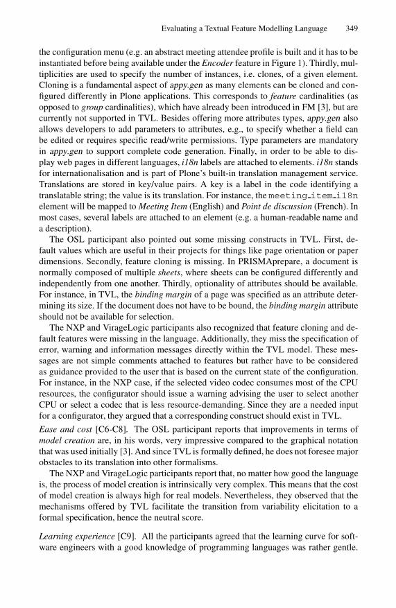
Evaluating a Textual Feature Modelling Language 349
the configuration menu (e.g. an abstract meeting attendee profile is built and it has to beinstantiated before being available under the Encoder feature in Figure 1). Thirdly, mul-tiplicities are used to specify the number of instances, i.e. clones, of a given element.Cloning is a fundamental aspect of appy.gen as many elements can be cloned and con-figured differently in Plone applications. This corresponds to feature cardinalities (asopposed to group cardinalities), which have already been introduced in FM [3], but arecurrently not supported in TVL. Besides offering more attributes types, appy.gen alsoallows developers to add parameters to attributes, e.g., to specify whether a field canbe edited or requires specific read/write permissions. Type parameters are mandatoryin appy.gen to support complete code generation. Finally, in order to be able to dis-play web pages in different languages, i18n labels are attached to elements. i18n standsfor internationalisation and is part of Plone’s built-in translation management service.Translations are stored in key/value pairs. A key is a label in the code identifying atranslatable string; the value is its translation. For instance, the meeting item i18nelement will be mapped to Meeting Item (English) and Point de discussion (French). Inmost cases, several labels are attached to an element (e.g. a human-readable name anda description).
The OSL participant also pointed out some missing constructs in TVL. First, de-fault values which are useful in their projects for things like page orientation or paperdimensions. Secondly, feature cloning is missing. In PRISMAprepare, a document isnormally composed of multiple sheets, where sheets can be configured differently andindependently from one another. Thirdly, optionality of attributes should be available.For instance, in TVL, the binding margin of a page was specified as an attribute deter-mining its size. If the document does not have to be bound, the binding margin attributeshould not be available for selection.
The NXP and VirageLogic participants also recognized that feature cloning and de-fault features were missing in the language. Additionally, they miss the specification oferror, warning and information messages directly within the TVL model. These mes-sages are not simple comments attached to features but rather have to be consideredas guidance provided to the user that is based on the current state of the configuration.For instance, in the NXP case, if the selected video codec consumes most of the CPUresources, the configurator should issue a warning advising the user to select anotherCPU or select a codec that is less resource-demanding. Since they are a needed inputfor a configurator, they argued that a corresponding construct should exist in TVL.
Ease and cost [C6-C8]. The OSL participant reports that improvements in terms ofmodel creation are, in his words, very impressive compared to the graphical notationthat was used initially [3]. And since TVL is formally defined, he does not foresee majorobstacles to its translation into other formalisms.
The NXP and VirageLogic participants report that, no matter how good the languageis, the process of model creation is intrinsically very complex. This means that the costof model creation is always high for real models. Nevertheless, they observed that themechanisms offered by TVL facilitate the transition from variability elicitation to aformal specification, hence the neutral score.
Learning experience [C9]. All the participants agreed that the learning curve for soft-ware engineers with a good knowledge of programming languages was rather gentle.

350 A. Hubaux et al.
Software engineers who use only graphical models might need a little more time to feelcomfortable with the syntax. In fact, the NXP and VirageLogic participants believe thatpeople in their teams well versed in programming languages would give a + whereasthose used to modelling languages would give a , hence their average + score.
6 Findings
This sections builds upon the analysis by looking at the results from three differentangles: (1) the constructs missed by TVL, (2) the impact of stakeholder profiles on theuse of TVL, and (3) the tool support that is provided and still to provide.
6.1 Language Constructs
The analysis revealed that extensions to the catalogue of constructs provided by TVLwould be appreciated by the participants. We summarise below those that neither makethe language more complex nor introduce extraneous information (such as, e.g., be-havioural specifications) into the language.
Attribute cardinality. Traditionally, the cardinality of an attribute is assumed to be〈1..1〉 (oneOf), i.e. one and only one element in its domain can be selected. How-ever, the translation of select lists in PloneMeeting would have required enumera-tions with cardinalities. For instance, in Figure 3, the vote encoders would typicallybe captured in a select list, which should be translated into an enumeration with car-dinality 〈1..2〉. The absence of cardinality for enumerations forced us to translatethem has features. Yet, these select lists typically allow multiple selections, i.e. theyrequire a cardinality like 〈1..n〉 (someOf). Additionally, optional attributes, likethe binding margin, would require a 〈0..1〉 (opt) cardinality. Technically, arbitrarycardinalities for attributes are a simple extension of the decomposition operatorsdefined for features. Their addition to TVL will thus be straightforward.
Cloning. All the participants expressed a need for cloning in FMs. They have not beenintroduced in TVL because of the theoretical problems they yield, viz. reasoningabout potentially infinite configuration spaces and managing clone-specific con-straints. Feature cardinalities will thus be proposed in TVL when all the reasoningissues implied by cloning will be solved. This is work in progress.
Default values. The main advantage of default values is to speed up product configura-tion by pre-defining values (e.g. the default page orientation). The participant fromOSL argued that, if their applications were to include a TVL-based configurationengine, then TVL should contain default values. This would avoid having defaultvalues scattered in the source code, thereby limiting the maintenance effort.
Extended type set. Far more types are needed in PloneMeeting than TVL offers. Ourexperience and discussions with the developers show that only some of them shouldbe built in the language. For this reason, only the String, Date and File typeswill be added to TVL.
Import mechanism. In addition to the include mechanism, the participantsrequested a more fine grained import mechanism. This will require to add scop-ing to TVL.

Evaluating a Textual Feature Modelling Language 351
Labels and messages. In the PloneMeeting case, the participant showed that labelshave to be attached to features to provide the user with human-readable featurenames and description fields, and also to propose multilingual content.Both the NXP and VirageLogic participants use messages to guide the configu-ration of their products. Constraints on features determine the messages that aredisplayed based on the current configuration status.
Specialisation. In two cases, specialisation mechanisms appeared to be desirable con-structs. They would typically allow to overload or override an existing FM, for ex-ample, by adding or removing elements from previously defined enum, structand feature groups, or by refining cardinalities, e.g. from 〈0..∗〉 to 〈2..3〉.
The extensions that could have been added to TVL but that, we thought, would makeit deviate too much from its purpose are the following.
Abstraction. Although particularly useful for programming languages (e.g. abstractclasses in object-oriented programming), we do not see the interest of using abstractFMs. FMs are, by definition, not meant to be instantiated but to be configured.
Method definition. TVL provides a static description of the variability of a PL. Meth-ods, even declarative, would embed behavioural specifications within the language.This is neither an intended purpose nor a desired property of the language. Anymethod manipulating the FM should be defined externally.
Typed parameters. In PloneMeeting, typed parameters are extensively used. How-ever, many of these parameters are very technical and case-specific, e.g. editable orsearchable fields. Unless we come across more use cases, we will not add param-eters to attributes. For cases like PloneMeeting, these parameters can be encodedwith the data construct.
6.2 Stakeholder Profiles
As shown in Table 2, the participants had fairly different profiles. Our population con-sists of two developers, one designer and two project managers. Their experience withPLs and FMs also differ. Two participants are intensive users, one is a regular and theother two are still in the transition phase, i.e. moving from traditional to PL engineering.
Interestingly, these profiles did not have a noticeable influence on the marks givento the notation (C1-C3), ease and cost (C6-C8), and learning experience (C9). Theyall preferred and attribute grammar-like syntax to a markup-based language like XML,usually considered too verbose, difficult to read and tricky to edit. Furthermore, the C-like syntax was deemed to preserve many programming habits—like code layout, thedevelopment environment, etc.
Deviations appear at the level of modularisation (C4) and expressiveness (C5). Oneway to interpret it is that OSL and PloneMeeting are still in the transition phase. Thismeans that they are not yet confronted to variability modelling tools in their daily work.They are more familiar with traditional modelling languages like UML and program-ming languages like C++ and Python. Compared to these languages, FMs, and TVLin particular, are more specific and thus far less expressive. Furthermore, in the Plone-Meeting case, the participant developed its own all-in-one website configuration and

352 A. Hubaux et al.
generation tool, which embeds a domain specific language for statechart and class dia-gram creation.
These observations lead us to conclude that:
stakeholder profiles do no impact the evaluation of the notation. Developers clearlyappreciated the textual alternative proposed by TVL. The ease and efficiency ofuse are the main reasons underlying that preference. Thanks to their knowledgeof programming languages, developers naturally prefer to write code than drawlines and boxes. This is usually seen as a time-consuming and clerical task, evenwith proper tool support. Surprisingly, the participants who were used to graphicalmodels also positively evaluated TVL. They not only liked the language but alsothe convenience offered by the textual edition interface.
stakeholder profiles influence the preference for the configuration model. The de-velopers looked for ways to reuse the TVL model for configuration purposes. Theirsuggestion was to remove the unnecessary elements from the TVL model (unse-lected features and attributes) and directly use it as a product specification. Theadvantage of this approach is that comparison between products could be imme-diately achieved with a simple diff. In contrast, the designers were in favour of agraphical model, e.g. a tree-shaped FM, or more elaborate configuration interfaceslike configuration wizards or tables.
6.3 Tool Support
At the moment, TVL only comes with a parser that checks syntactic and type correct-ness, as well as a configuration engine that supports decision propagation limited toBoolean values. We have also developed plugins for tree editors, namelly NotePad++(Windows), Smultron (MacOS) and TextMate (MacOS). These plugins provide basicsyntax highlighting and collapse/expand mechanisms to hide/show pieces of code.
Besides textual editors, out-of-the-box versioning tools like CVS or Subversion al-ready support the collaborative editing of TVL models as any other text file, as reportedby the OSL and Virage Logic participants. The interpretation of a change made to aTVL line is as easy as it is for programming code. By simply looking at the log, onecan immediately see who changed what and when. In contrast, graphical models usu-ally require dedicated tools with their own encoding, which makes interoperability andcollaboration difficult.
The configuration capabilities of TVL have recently been applied to re-engineer theconfiguration menu of PloneMeeting. This resulted in a prototype that demonstrateshow it is possible to use an application-specific web interface as frontend for a genericTVL-based configurator. Although very limited in functionality, the prototype gave theparticipant a better overview of the benefits of TVL. Surprisingly, the PloneMeetingparticipant was not interested in generating appy.gen code from a TVL model becauseof the Python code that would still have to be edited after generation. However, gen-erating a TVL model from appy.gen code would greatly simplify constraint specifica-tion and validation. Tedious and error-prone Python code would no longer have to bemaintained manually, and most of the constraints that are only available in the head ofdevelopers would become trivial to implement. Put simply, TVL would be used here

Evaluating a Textual Feature Modelling Language 353
as a domain-specific constraint language. We could not produce similar prototypes forthe other cases because configuration interfaces were not available and/or access to thecode was not granted.
A functionality not provided by the TVL tools but requested by the participants iscode completion of language constructs, feature names and attributes. Another impor-tant functionality would be the verification of the scope of features in constraints. Sincea constraint can contain any feature in the FM, it might rapidly become hard to identifywhether the referenced feature is unique or if a relative path to it has to be given. Theon-the-fly suggestion of alternative features by the editor would facilitate constraintdefinition and make it less error-prone. By extension, the on-the-fly checking of thesatisfiability of the model would avoid wasting time later on debugging it. The down-side of such checks is that they can be resource-intensive and should thus be carefullyscheduled and optimized.
7 Threats to Validity
The evaluation was performed with four PLs and five participants, providing a diversityof domains and profiles. Yet, their diversity did not have a significant influence on theresults since we observed a substantial overlap between their comments. Therefore, webelieve that the results are valid for wide a range of organizations and products [36].
The TVL models were prepared in advance by the two researchers and later checkedby the participants. Consequently, the expertise of the researchers might have influ-enced the models and the evaluation of the participants. In order to assess this poten-tial bias more precisely, we will have to compare models designed by participants tomodels designed by the two researchers. However, TVL is arguably simpler than mostprogramming languages and the modelling task was felt to be rather straightforward.As as consequence, we do not expect this to be a problem for our evaluation. Further-more, when the participants questioned the design decisions, alternative solutions werediscussed based on the constructs available in the language—even those not disclosedduring the presentation.
The limited hands-on experience with TVL might have negatively influenced theevaluation of the expressiveness, notation and modularisation of the language, and pos-itively impacted the evaluation of the ease and cost and learning experience. That situa-tion resembles the setting of an out-of-box experience [37]. This gives valuable insightas to how software engineers perceive TVL after a one-hour training and how fast theycan reach a good understanding of the fundamental concepts.
A more specific problem was the unavailability of proper documentation and thelimited access granted to the codebase in the case of OSL, NXP and Virage Logic. Thismade the modelling of those cases more difficult.
In the case of OSL, the development team is still in the SPL adoption phase. Thiscould be a threat as the participant has only been exposed to FMs for reviewing. There-fore, he might have focused on comparing the textual and graphical approaches ratherthan evaluating the language itself. Along the same lines, the PloneMeeting participantwas already reluctant to use graphical FMs and might have evaluated the textual ap-proach rather than TVL itself. In any case, we believe that the feedback received was

354 A. Hubaux et al.
more shaped by the expectations and requirements of the participants than by the pref-erence for a textual representation over a graphical one.
More generally, one limitation of our study is the relatively small size of the subsys-tems we could deal with during the experiment.
8 Conclusion
Effective representations of FMs are an open research question. Textual alternativeshave been proposed, including TVL, a textual variability modelling language meant toovercome a number of known deficiencies observed in other languages. Yet, evidence ofthe suitability of TVL in practice was missing. In this paper, we systematically evaluatedthe language by conducting an empirical evaluation on four industrial product lines.
Our evaluation of TVL showed that practitioners positively evaluated the notationand that efficiency gains are envisioned in terms of model comprehension, design andlearning curve. However, they suggested some extensions like attribute cardinalities,feature cloning, default values and guidance messages that can be used during productconfiguration.
In the future we will focus on integrating the recommended extensions into TVL.Furthermore, the prototype implementation of the TVL parser and reasoner needs to beextended to better support on-the-fly verification of model consistency. To assess thesenew extensions, live evaluations through modelling sessions are envisaged. To betterassess the pros and cons of variability modelling languages, comparative evaluationsare planned, too.
Acknowledgements
We would like to thank Gaetan Delannay from GeezTeem, Jacques Flamand from OSL,Hans den Boer and Jos Hegge from Virage Logic for the time they dedicated to ourevaluation, and Bart Caerts from NXP Semiconductors for his contribution to the de-velopment of the CPU-load calculation variability model. This work is sponsored by theInteruniversity Attraction Poles Programme of the Belgian State, Belgian Science Pol-icy, under the MoVES project, the Walloon Region under the NAPLES and the FIRSTDOC.A programmes.
References
1. Kang, K., Cohen, S., Hess, J., Novak, W., Peterson, S.: Feature-oriented domain analysis(foda) feasibility study. Technical Report CMU/SEI-90-TR-21, SEI, Carnegie Mellon Uni-versity (November 1990)
2. Pohl, K., Bockle, G., van der Linden, F.: Software Product Line Engineering: Foundations,Principles and Techniques. Springer, Heidelberg (2005)
3. Czarnecki, K., Helsen, S., Eisenecker, U.W.: Formalizing cardinality-based feature modelsand their specialization. Software Process: Improvement and Practice 10(1), 7–29 (2005)
4. Schobbens, P.Y., Heymans, P., Trigaux, J.C., Bontemps, Y.: Generic semantics of feature di-agrams. Computer Networks, Special Issue on Feature Interactions in Emerging ApplicationDomains, 38 (2006)

Evaluating a Textual Feature Modelling Language 355
5. pure-systems GmbH: Variant management with pure: variants. Technical White Paper(2006), http://www.pure-systems.com/fileadmin/downloads/pv-whitepaper-en-04.pdf
6. van Deursen, A., Klint, P.: Domain-specific language design requires feature descriptions.Journal of Computing and Information Technology 10, 2002 (2002)
7. Batory, D.S.: Feature models, grammars, and propositional formulas. In: Obbink, H., Pohl,K. (eds.) SPLC 2005. LNCS, vol. 3714, pp. 7–20. Springer, Heidelberg (2005)
8. Boucher, Q., Classen, A., Faber, P., Heymans, P.: Introducing TVL, a text-based feature mod-elling language. In: VaMoS 2010, University of Duisburg-Essen, pp. 159–162 (January 2010)
9. Czarnecki, K.: From feature to concept modeling. In: VaMoS 2010, University of Duisburg-Essen, 11 Keynote (January 2010)
10. Nestor, D., O’Malley, L., Sikora, E., Thiel, S.: Visualisation of variability in software productline engineering. In: VaMoS 2007 (2007)
11. Cawley, C., Healy, P., Botterweck, G., Thiel, S.: Research tool to support feature configura-tion in software product lines. In: VaMoS 2010, University of Duisburg-Essen, pp. 179–182(January 2010)
12. Dordowsky, F., Hipp, W.: Adopting software product line principles to manage softwarevariants in a complex avionics system. In: SPLC 2009, San Francisco, CA, USA, pp. 265–274 (2009)
13. Classen, A., Boucher, Q., Faber, P., Heymans, P.: The TVL Specification. Technical report,PReCISE Research Centre, Univ. of Namur (2009)
14. Shull, F., Singer, J., Sjøberg, D.I.K.: Guide to Advanced Empirical Software Engineering.Springer-Verlag New York, Inc., Secaucus (2007)
15. Schobbens, P.Y., Heymans, P., Trigaux, J.C., Bontemps, Y.: Feature Diagrams: A Survey andA Formal Semantics. In: RE 2006, pp. 139–148 (September 2006)
16. Antkiewicz, M., Czarnecki, K.: Featureplugin: feature modeling plug-in for eclipse. In: OOP-SLA 2004, pp. 67–72 (2004)
17. Beuche, D.: Modeling and building software product lines with pure::variants. In: SPLC2008: Proceedings of the 2008 12th International Software Product Line Conference, Wash-ington, DC, USA, p. 358. IEEE Computer Society, Los Alamitos (2008)
18. Kastner, C., Thum, T., Saake, G., Feigenspan, J., Leich, T., Wielgorz, F., Apel, S.: Fea-tureIDE: A tool framework for feature-oriented software development. In: Proceedings ofICSE 2009, pp. 311–320 (2009)
19. Krueger, C.W.: Biglever software gears and the 3-tiered spl methodology. In: OOPSLA 2007:Companion to the 22nd ACM SIGPLAN Conference on Object-Oriented Programming Sys-tems and Applications Companion, pp. 844–845. ACM, New York (2007)
20. Mendonca, M., Branco, M., Cowan, D.: S.p.l.o.t. - software product lines online tools. In:Proceedings of OOPSLA 2009, pp. 761–762 (2009)
21. Mendonca, M.: Efficient Reasoning Techniques for Large Scale Feature Models. PhD thesis,University of Waterloo (2009)
22. Reiser, M.O.: Core concepts of the compositional variability management framework (cvm).Technical report, Technische Universitat Berlin (2009)
23. Abele, A., Johansson, R., Lo, H., Papadopoulos, Y., Reiser, M.O., Servat, D., Torngren,M., Weber, M.: The cvm framework - a prototype tool for compositional variability man-agement. In: Proceedings of the Fourth International Workshop on Variability Modellingof Software-intensive Systems (VaMoS 2010), University of Duisburg-Essen, pp. 101–105(January 2010)
24. Benavides, D., Segura, S., Trinidad, P., Cortes, A.R.: Fama: Tooling a framework for theautomated analysis of feature models. In: Proceedings of VaMoS 2007, pp. 129–134 (2007)
25. Riebisch, M., Bollert, K., Streitferdt, D., Philippow, I.: Extending feature diagrams with umlmultiplicities. In: IDPT 2002 (2002)

356 A. Hubaux et al.
26. Czarnecki, K., Bednasch, T., Unger, P., Eisenecker, U.W.: Generative programming for em-bedded software: An industrial experience report. In: Batory, D., Blum, A., Taha, W. (eds.)GPCE 2002. LNCS, vol. 2487, pp. 156–172. Springer, Heidelberg (2002)
27. Pratt, T.W.: Programming Languages: Design and Implementation, 2nd edn., 604 pages.Prentice-Hall, Englewood Cliffs (1984)
28. Holtz, N., Rasdorf, W.: An evaluation of programming languages and language features forengineering software development. Engineering with Computers 3, 183–199 (1988)
29. PloneGov. (June 2010), http://www.plonegov.org/30. Delannay, G., Mens, K., Heymans, P., Schobbens, P.Y., Zeippen, J.M.: Plonegov as an open
source product line. In: OSSPL 2007, collocated with SPLC 2007 (2007)31. Hubaux, A., Heymans, P., Benavides, D.: Variability modelling challenges from the trenches
of an open source product line re-engineering project. In: SPLC 2008, Limerick, Ireland, pp.55–64 (2008)
32. Unphon, H., Dittrich, Y., Hubaux, A.: Taking care of cooperation when evolving sociallyembedded systems: The plonemeeting case. In: CHASE 2009, collocated with ICSE 2009(May 2009)
33. Oce Software Laboratories, S.A (June 2010), http://www.osl.be/34. NXP Semiconductors (June 2010), http://www.nxp.com/35. Virage Logic (June 2010), http://www.viragelogic.com/36. Yin, R.K.: Case Study Research: Design and Methods, 3rd edn. Applied Social Research
Methods, vol. 5. Sage Publications, Inc., Thousand Oaks (2002)37. Sangwan, S., Hian, C.K.: User-centered design: marketing implications from initial expe-
rience in technology supported products. In: Press, I.C.S. (ed.) Engineering ManagementConference, vol. 3, pp. 1042–1046 (2004)

Extending DMM Behavior Specifications for
Visual Execution and Debugging
Nils Bandener, Christian Soltenborn, and Gregor Engels
University of Paderborn, Warburger Straße 100, 33098 Paderborn, Germany{nilsb,christian,engels}@uni-paderborn.de
Abstract. Dynamic Meta Modeling (DMM) is a visual semantics spec-ification technique targeted at behavioral languages equipped with ametamodel defining the language’s abstract syntax. Given a model anda DMM specification, a transition system can be computed which repre-sents the semantics of that model. It allows for the investigation of themodel’s behavior, e.g. for the sake of understanding the model’s seman-tics or to verify that certain requirements are fulfilled. However, due toa number of reasons such as tooling and the size of the resulting transi-tion systems, the manual inspection of the resulting transition system iscumbersome.
One solution would be a visualization of the model’s behavior usinganimated concrete syntax. In this paper, we show how we have enhancedDMM such that visual execution and debugging can be added to a lan-guage in a simple manner.
1 Introduction
One challenge of today’s software engineering is the fact that software systemsbecome more and more complex, making it hard to produce systems which workcorrectly under all possible executions. As a result, the Object ManagementGroup (OMG) has proposed the approach of Model-Driven Architecture (MDA).The main idea of MDA is to start with an abstract, platform-independent modelof the system, and to then refine that model step by step, finally generatingplatform-specific, executable code.
In this process, behavioral models (e.g., UML Activities) play an increasinglyimportant role; they allow to model the system’s desired behavior in an abstract,visual way. This has a couple of advantages, one of the most important being thatsuch visual models can be used as a base for communication with the system’sstakeholders (in contrast to e.g. Java code).
However, to get the most usage out of behavioral models, their semantics hasto be defined precisely and non-ambiguously; otherwise, different interpretationsof a model’s meaning may occur, leading to all kinds of severe problems. Un-fortunately, the UML specification [15] does not fulfill that requirement: Thesemantics of the behavioral models is given as natural text, leaving room fordifferent interpretations.
B. Malloy, S. Staab, and M. van den Brand (Eds.): SLE 2010, LNCS 6563, pp. 357–376, 2011.c© Springer-Verlag Berlin Heidelberg 2011

358 N. Bandener, C. Soltenborn, and G. Engels
One solution would be to specify the semantics of these behavioral languageswith a formal semantics, i.e., some kind of mathematical model of the language’sbehavior. A major advantage of such a specification is that it can be processedautomatically, e.g. for verifying the specification for contradictory statements.
Dynamic Meta Modeling (DMM) [9,13] is a semantics specification techniquewhich results in semantics specifications that are not only formal, but also claimto be easily understandable. The only prerequisite for using DMM is that thesyntax of the language under consideration is defined by means of a metamodel.
In a nutshell, DMM works as follows: In a first step, the language engineercreates a so-called runtime metamodel by enhancing the syntax metamodel withconcepts needed to express states of execution of a model. For instance, in thecase of the UML, the specification states that “the semantics of UML Activitiesis based on token flow”. As a result, the runtime metamodel contains a Tokenclass.
The second step consists of creating operational rules which describe how in-stances of the runtime metamodel change through time. For instance, the DMMspecification for UML Activities contains a rule which makes sure that an Actionis executed as soon as Tokens are sitting on all incoming ActivityEdges of thatAction.
Now, given a model (e.g., a concrete UML Activity) and an according DMMspecification, a transition system can be computed, where states are instances ofthe runtime metamodel (i.e., states of execution of the model), and transitionsare applications of the operational rules. The transition system represents thecomplete behavior of the model under consideration and can therefore be usedfor answering all kinds of questions about the model’s behavior.
However, investigating such a transition system is a difficult and cumbersometask for a number of reasons. First of all, we have seen that the states of thetransition system are instances of the runtime metamodel, which can be prettydifficult to comprehend. Additionally, due to the so-called state explosion prob-lem, the transition systems tend to be pretty large.
One solution for (at least partly) solving this problem would be to show theexecution of a model in the model’s own concrete syntax. This has two majorbenefits:
– It is significantly easier to find interesting states of execution, e.g., situationswhere a particular Action is executed.
– Investigating the states of the transition system only is an option for ad-vanced language users, i.e., people who are at least familiar with the lan-guage’s metamodel. In contrast, visualizing the model execution in concretesyntax is much easier to comprehend.
In this paper, we show how we extended the DMM approach to allow for exactlythat. We will show how the language engineer (i.e., the person who definesa modeling language) can make her language visualizable and debuggable byadding a couple of simple models containing all information necessary to visualizea model’s execution, and how this information is used to extend existing visualeditors at runtime for the sake of showing the model execution. As a result, the

Extending DMM Behavior Specifications 359
language engineer can make the language under consideration visualizable anddebuggable without writing a single line of code.
Structure of paper. In the next section, we will give a short introduction toDMM, and we will briefly introduce the components we used to implement modelvisualization in a generic way. Based on that, Sect. 3 will show what informationthe language engineer has to provide, and how this information is specified bymeans of certain configuration models. Finally, Sect. 3 will briefly explain howwe integrated our approach into the existing tooling. Section 5 will discuss workrelated to our approach, and finally, Sect. 6 will conclude and point out somefuture work.
2 Dynamic Meta Modeling
This section introduces the foundations needed for the understanding of themain section 3. It gives a very brief introduction to Dynamic Meta Modeling(DMM).
As already mentioned in the introduction, DMM is a language dedicated tothe specification of behavioral semantics of languages whose syntax is definedby means of a metamodel. The general idea is to enhance the syntax metamodelwith information needed to express states of execution of a model; the enhancedmetamodel is called runtime metamodel. The actual behavior is then specifiedby means of operational rules which are typed over the runtime metamodel.
Given such a runtime metamodel and a set of DMM rules, a transition sys-tem can be computed. This is done as follows: First, a semantic mapping is usedto map an instance of the syntax metamodel into an instance of the runtimemetamodel; that model will then serve as the initial state of the transition sys-tem to be computed. Now, all matching DMM rules are applied to the initialstate, resulting in a number of new states. This process is repeated until no newstates are discovered. The resulting transition system represents the completebehavior of a particular model. It can then e.g. be analyzed with model checkingtechniques (see [10]). An overview of the DMM approach is depicted as Fig. 1.
Let us demonstrate the above using the language of UML Activities. A carefulinvestigation of the UML specification reveals that the semantics of Activitiesis based on tokens flowing through the Activity; as consequence, two runtimestates of the same Activity differ in the location of the flowing tokens.
In fact, the semantics is significantly more difficult: Tokens do not actuallyflow through an Activity. Instead, they are only offered to ActivityEdges. Onlyif an Offer arrives at an Action (and that Action is being executed), the Tokenowning the Offer moves. Figure 2 shows an excerpt of the runtime metamodel forUML Activities; elements depicted in white are part of the syntax metamodel,gray elements belong to the runtime part of the metamodel.
Now for the specification of the semantics’ dynamic part: As mentioned above,this is done by operational rules. A DMM rule basically is an annotated objectdiagram. It matches a state if the rule’s object structure is contained in thatstate. If this is the case, the rule is applied, i.e., the modifications induced by

360 N. Bandener, C. Soltenborn, and G. Engels
Semantics Definition
Syntax Definition
Transition System
States
Expression
Model
Operational rules
conforms to
Semantic metamodeling
conforms to
Metamodel Graph transformation rules
semantic mapping Runtime metamodel
conforms toconforms to
typedover
Fig. 1. Overview of the DMM approach
Fig. 2. Excerpt of the runtime metamodel
Fig. 3. DMM Rule decisionNode.flow()

Extending DMM Behavior Specifications 361
the annotations are performed on the found object structure, leading to a newstate.
Figure 3 shows a simple DMM rule with name decisionNode.flow(). Its seman-tics is as follows: The rule matches if the incoming ActivityEdge of a DecisionNodecarries an Offer. If this is the case, the Offer is moved to one of the outgoing edges.Note that usually, a DecisionNode has more than one outgoing edge. In this case,the rule’s object structure is contained in the state more than once; every oc-curence consists of the incoming ActivityEdge, the DecisionNode, the Offer, andone of the outgoing ActivityEdges. As a result, we will end up with a new statefor every outgoing edge, and the states will differ in the location of the Offer(which will sit on the according outgoing edge of that state). In other words: Weend up with one new state for every possible way the Offer can go.
Note that DMM specifications usually do not aim at making models exe-cutable – if this would be the case, rule 3 would need to evaluate the guards ofthe DecisionNode’s outgoing edges to determine the edge to which the Offer hasto be routed. Instead, the transition system representing the model’s behaviorcontains all possible executions of that model. This allows to analyze the be-havior of Activities which are modeled rather informally (e.g., if the guards arestrings such as “Claim valid”). See [10] for an example of such an analysis.
Technically, DMM rules are typed graph transformation rules (GTRs) [18].DMM supports a couple of advanced features: For instance, universally quantifiedstructures can be used to manipulate all occurrences of a node within one rule;negative application conditions allow to describe object structures which preventa rule from matching; additionally, DMM allows for the usage and manipulationof attributes.
The main difference to common GTRs is the fact that DMM rules come intwo flavors: bigstep rules and smallstep rules. Bigstep rules basically work ascommon GTRs: They are applied as soon as they match as described above.In contrast, smallstep rules have to be explicitly invoked by a bigstep rule oranother smallstep rule;1 as long as there are smallstep rules which have beeninvoked, but are yet to be processed, bigstep rules cannot match.
To actually compute a transition system from a model and a DMM seman-tics specification, the model as well as the set of DMM rules are translatedinto a graph grammar suitable for the graph transformation toolGROOVE [17]. Slightly simplified, this is done as follows: The model is trans-lated into a GROOVE state graph which serves as the initial state of the tran-sition system to be computed. Furthermore, each DMM rule is translated intoan according GROOVE rule; features not directly supported by GROOVE aretranslated into structures within the GROOVE rules which make sure that theDMM rule’s behavior is reflected by the GROOVE rule. For instance, to be ableto handle invocation of rules, an actual invocation stack is added to the initial
1 Note that the invocation of a smallstep rule might fail in case it is invoked, butthe object structure required by the invoked rule is not contained in the currentstate, resulting in the rule not matching; a DMM semantics specification potentiallyleading to such situations is considered to be broken.

362 N. Bandener, C. Soltenborn, and G. Engels
state, and the GROOVE rules have structures which manipulate that invoca-tion stack and make sure that smallstep rules can only match if an accordinginvocation is on top of the stack.
3 Visual Model Execution
With DMM, we can define the semantics of a modeling language, calculate ex-ecution states of model instances, and apply further analytical methods to it.Yet, the basic concept of DMM provides no means to visualize the executionand the therein occurring states of a model; a feature which is feasible for mon-itoring, better understanding, or debugging a model—especially if it is writtenin a visual language.
Thus, we have developed a tool for visually executing and debugging modelswith DMM-specified semantics, the DMM Player [1]. From a technical perspec-tive, the tool is a set of Eclipse plug-ins, which is able to process models andDMM semantics specified with the Eclipse Modeling Framework (EMF) [5]. Thevisualization is realised using the Graphical Modeling Framework (GMF) [7],which is the standard way of providing visual editors for EMF-based models. Asthere are already numerous existing GMF editors for behavioral models which—however—do not support displaying runtime-information such as tokens or activestates, the DMM Player also provides means to augment existing editors by suchelements.
Leaving those pesky technical details behind, we will now focus on the under-lying concepts which make the visualization of a model execution possible. UsingUML Activities as a running example, we start with the fundamental question onhow to visualize execution states and how the augmentation of existing visualiza-tions can be specified in a model-driven way. Beneath the graphical dimensions,we will also have to consider the time axis when visualizing the execution. Thiswill be covered in Sect. 3.2. Section 3.3 covers means of controlling the execu-tion path when external choices are necessary. Section 3.4 introduces conceptsthat make debugging of models in the presented environment possible. Finally,in Sect. 3.5 we will demonstrate our approach on another language, i.e., UMLStatemachines.
3.1 Visualizing Runtime Information
In order to visualize the behavior of a model, i.e., the development of its run-time state over time, it is obviously essential to be able to visualize the model’sruntime state at all. However, this cannot be taken for granted. While certainvisual languages have an inherent visual syntax for runtime information—suchas Petri nets [16] visualizing the state using tokens on places—many visual lan-guages only support the definition of the static structure—such as UML activitydiagrams.
The specification for activity diagrams only informally describes the seman-tics using concepts such as tokens, which are comparable to the tokens usedby Petri nets, and offers, which act as a kind of path finder for tokens. The
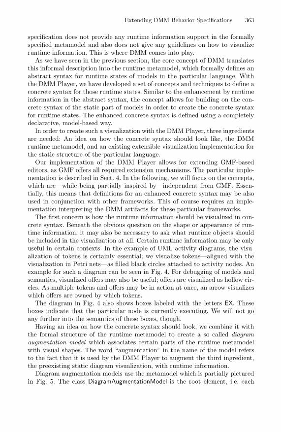
Extending DMM Behavior Specifications 363
specification does not provide any runtime information support in the formallyspecified metamodel and also does not give any guidelines on how to visualizeruntime information. This is where DMM comes into play.
As we have seen in the previous section, the core concept of DMM translatesthis informal description into the runtime metamodel, which formally defines anabstract syntax for runtime states of models in the particular language. Withthe DMM Player, we have developed a set of concepts and techniques to define aconcrete syntax for those runtime states. Similar to the enhancement by runtimeinformation in the abstract syntax, the concept allows for building on the con-crete syntax of the static part of models in order to create the concrete syntaxfor runtime states. The enhanced concrete syntax is defined using a completelydeclarative, model-based way.
In order to create such a visualization with the DMM Player, three ingredientsare needed: An idea on how the concrete syntax should look like, the DMMruntime metamodel, and an existing extensible visualization implementation forthe static structure of the particular language.
Our implementation of the DMM Player allows for extending GMF-basededitors, as GMF offers all required extension mechanisms. The particular imple-mentation is described in Sect. 4. In the following, we will focus on the concepts,which are—while being partially inspired by—independent from GMF. Essen-tially, this means that definitions for an enhanced concrete syntax may be alsoused in conjunction with other frameworks. This of course requires an imple-mentation interpreting the DMM artifacts for these particular frameworks.
The first concern is how the runtime information should be visualized in con-crete syntax. Beneath the obvious question on the shape or appearance of run-time information, it may also be necessary to ask what runtime objects shouldbe included in the visualization at all. Certain runtime information may be onlyuseful in certain contexts. In the example of UML activity diagrams, the visu-alization of tokens is certainly essential; we visualize tokens—aligned with thevisualization in Petri nets—as filled black circles attached to activity nodes. Anexample for such a diagram can be seen in Fig. 4. For debugging of models andsemantics, visualized offers may also be useful; offers are visualized as hollow cir-cles. As multiple tokens and offers may be in action at once, an arrow visualizeswhich offers are owned by which tokens.
The diagram in Fig. 4 also shows boxes labeled with the letters EX. Theseboxes indicate that the particular node is currently executing. We will not goany further into the semantics of these boxes, though.
Having an idea on how the concrete syntax should look, we combine it withthe formal structure of the runtime metamodel to create a so called diagramaugmentation model which associates certain parts of the runtime metamodelwith visual shapes. The word “augmentation” in the name of the model refersto the fact that it is used by the DMM Player to augment the third ingredient,the preexisting static diagram visualization, with runtime information.
Diagram augmentation models use the metamodel which is partially picturedin Fig. 5. The class DiagramAugmentationModel is the root element, i.e. each

364 N. Bandener, C. Soltenborn, and G. Engels
augmentation model contains exactly one instance of this class. The attributediagramType is used to associate a particular diagram editor with the augmenta-tion model - this diagram editor will then be used for displaying runtime states.
The actual elements to be visualized are determined by the classes Augmen-tationNode and AugmentationEdge. More precisely, as both classes are abstract,subclasses of these classes must be used in an instance of the meta model. Thesubclasses determine the implementation type of the visualization.
The way the elements are integrated into the existing diagram is determinedby the references between AugmentationNode and AugmentationEdge on the oneside and EReference and EClass on the other side. The latter two classes stem fromthe Ecore metamodel, which is the EMF implementation of the meta-metamodelstandard MOF. They represent elements from the DMM runtime metamodel thevisualization is supposed to be based on.
In the case of an AugmentationNode, the following references need to be set:The reference augmentationClass determines the class from the runtime meta-model which is visualized by this particular node; however, this is not sufficient,as the class needs to be somehow connected to elements that already exist inthe visualization of the static structure. For instance, a token is linked to anactivity node and should thus be visually attached to that node. This connec-tion is realized by the reference named references; it must point to an EReferenceobject which emanates from the referenced augmentationClass or one of its superclasses. The EReference object in turn must point towards the model element theaugmenting element should be visually attached to. Thus, this model elementmust stem from the static metamodel and must be visualized by the diagramvisualization to be augmented. The reference containment is only relevant if theuser shall be able to create new elements of the visualized type directly in theeditor; those elements will be added into the containment reference specifiedhere.
Figure 6 shows the part of the augmentation model for UML activities whichspecifies the appearance of control tokens, which are a subclass of tokens. The ref-erences link specifies that the reference named contained in determines to whichActivityNode objects the new nodes should be attached to. The references linkis part of the class Token. However, as the link augmentationClass specifies theclass ControlToken as the class to be visualized, this particular ShapeAugmenta-tionNode will not come into effect when other types of tokens occur in a runtimemodel. Thus, other augmentation nodes may be specified for other tokens.
3.2 Defining the Steps of Executions
Being able to visualize individual runtime states, creating animated visualiza-tions of a model’s behavior is straightforward. Sequentially applying the rules ofthe DMM semantics specification yields a sequence of runtime states which canbe visualized with a brief pause in-between, thus creating an animation.
However, the sequence of states produced by DMM is not necessarily wellsuited for a visualization. In many cases, subsequent states only differ in partsthat are not visualized. These parts are primarily responsible for internal

Extending DMM Behavior Specifications 365
Fig. 4. An UML activity diagram with additional runtime elements
Fig. 5. Excerpt of the metamodel for diagram augmentation models
Fig. 6. Excerpt of the augmentation model for UML activities

366 N. Bandener, C. Soltenborn, and G. Engels
information which is specific to the particular implementation of the seman-tics, but is not relevant for the behavior of the final model. Including these stepsin the animation would cause strange, irregular pauses between visual steps.
Furthermore, DMM semantics may produce states with temporary inconsis-tencies. These states also result from implementation details of the particularDMM semantics specification. DMM rules may modify a model using severalconsecutive invocations of other rules; this is necessary if the semantics of a lan-guage element is too complex to be described within one rule. Each invoked ruleproduces a new state, which however might be wrong—when viewed from puresemantics perspective without implementation details. In the case of the particu-lar implementation the state is of course still correct, as the subsequently invokedrules correct this inconsistency, thus making it a temporary inconsistency.
Figure 7 shows an example for a temporary inconsistency. In the first state, anoffer has reached the final node. The activity diagram semantics now demandsthat the corresponding token should be moved to the node reached by the offer.The DMM implementation of the semantics however creates a new token on thetarget node before removing the original token from its location. This createsthe exhibited temporary inconsistency with two tokens being visible at once.
The visualization of temporary inconsistencies might be interesting for thedeveloper of the DMM semantics implementation; for a user only interested inviewing the behavior of a model, such states should not be visualized.
Thus, we need a way of selecting the states that should be displayed to theuser. There is a number of different approaches to that problem which we willbriefly discuss in the following.
If the visualization of temporary inconsistencies is desired and only the afore-mentioned problem of steps without visual changes needs to be addressed, avery simple solution is obvious: Using the diagram augmentation model, it ispossible to determine what elements of the runtime model are visualized. TheDMM Player can use this information to scan the consecutive states for visualchanges; only if changes are detected, a visual step is assumed and thus promotedto the user interface.
If temporary inconsistencies are to be avoided in the visualization, other mea-sures need to be applied. A simple and straight-forward approach would be tovisualize only the state when the application of a Bigstep rule has been finished;application in this context means that the changes by the Bigstep rule and byits invocations have been performed. As temporary inconsistencies are typicallyraised by an invocation and again fixed by a consecutive invocation, temporaryinconsistencies will be fixed when all invocations have been finished and thusthe application of a bigstep rule has been finished.
Yet, the structuring concept of Bigstep and Smallstep rules has not been de-signed for visualization purposes; thus, it is also possible to find cases in whicha state produced by a Smallstep rule should be visualized while the applica-tion of the invoking Bigstep rule has not been finished yet. Just restricting thevisualization to states left by Bigstep rules is thus too restrictive.

Extending DMM Behavior Specifications 367
An obvious solution would be the explicit specification of all rules that shouldtrigger a visual step. This is, however, also the most laborious solution, as eachrule of the semantics specification needs to be checked. In the case of the DMM-based UML activity semantics specification, this means the inspection of 217rules.
Our solution for now is a combination of the approaches. Thus, in additionto the specification of individual rules triggering visual steps, the DMM Playeralso allows for the specification of all Bigstep rules. Furthermore, it is possi-ble to specify whether the visualization should be triggered before or after theapplication of the particular rules.
For creating a suitable animated visualization with the DMM UML activitysemantics, it is sufficient to trigger a visual step after the application of allBigstep rules and after the application of only one further Smallstep rule, whichtakes the responsibility of moving a token to the new activity node that hasaccepted the preceding offer.
3.3 Controlling Execution Paths
A limitation of the behavior visualization using an animated sequence of statesis its linearity. In some cases, the behavior of a model may not be unambiguouslydefined. For instance, this is the case in the activity diagram we have seen beforein Fig. 4; the left decision node has two outgoing transitions. Both are alwaysusable as indicated by the guard [true]. In a transition system, such a behavior isreflected by a fork of transitions leading from one state to several distinct states.In an animation, it is necessary to choose one path of the fork. At first sight, itis evident that such a choice should be offered to the user.
The DMM Player can offer this choice to the user by pausing the executionand visualizing the possible choices; after the user has made a choice, executioncontinues.
However, there are cases in which it is not feasible for the user to choosethe path to be used for every fork in the transition system. This is primarilythe case for forks caused by concurrency in the executed model. Even though alinear execution does not directly suffer from state space explosion, concurrencymight require a decision to be made before most steps of a model execution.
As the semantics of concurrency can be interpreted as an undefined executionorder, it is reasonable to let the system make the decision about the executionorder automatically. Forks in the transition system which are caused by modelconstructs with other semantics—such as decision nodes—should however sup-port execution control by user interaction.
The problem is now to distinguish transition system forks that should requireuser interaction from others. More precisely, as a single fork can both containtransitions caused by decision nodes and by concurrency, it is also necessary toidentify the portions of a fork that are supposed to form the choices given to theuser.
A basic measure for identifying the model construct that caused a fork or apart of it is considering the transformation rules that are used for the transitions

368 N. Bandener, C. Soltenborn, and G. Engels
forming the fork. In the case of the DMM semantics for UML activities, the tran-sitions which cause the forks at decision nodes are produced by the Bigstep ruledecisionNode.flow() (see also Fig. 3). Forks which consist of transitions causedby other rules can be regarded as forks caused by concurrency.
Just considering the rules causing the transitions is not sufficient, though.Concurrency might lead to forks which consist of decisionNode.flow() transitionsbelonging to different decision nodes in the model. If each of those decision nodehas only one active outgoing transition, there is no choice to be made by theuser but just choices purely caused by concurrency.
Thus, it is necessary to group the transitions at a fork by the model elementthey are related to. This model element can be identified by using the rule matchassociated to the particular transition (see Sect. 2 for a brief explanation of rulematching and application). The match is a morphism between the nodes of theparticular DMM rule and elements from the model. Generally, one node froma rule that is supposed to trigger a user choice can be used to identify therelated model element. In the case of the DMM activity semantics, this is the:DecisionNode element itself.
With these components, we can build an algorithm for identifying the in-stances of transition system forks in which the user should be asked for a choice:Group the transitions that are possible from the current state by the rule andby the elements bound to the grouping node defined for the particular rule. Ifthere is no grouping node or the rule is not supposed to cause user choices, theparticular transition forms a group of size one. Now one of these groups is ar-bitrarily chosen by the software; this reflects possible concurrency between thesingle groups. If the chosen group contains more than one transition, the useris requested to make a choice. Otherwise the single transition in the arbitrarilychosen group will be used to gather the next state.
This algorithm enables us to ensure that the user is only required to makechoices regarding single instances of certain model constructs, such as decisionnodes. A remaining problem is how to give the user an overview over the possiblechoices. We can again utilize nodes from the rules that are supposed to triggeruser choices. Those rules contain as a matter of principle always a node whichrepresents the different targets which can be reached while the aforementionedgrouping node stays constantly bound to the same model element. If the modelelement represented by the target node is part of the diagram, this diagramelement can be used for identifying the different choices.
In the case of UML activities, this is the target ActivityEdge node in therule decisionNode.flow(). The DMM Player can now use these model elements tovisualize the possible choices using generic marker signs as is depicted in Fig. 8.The user may easily select one of the choices using the context menu of one ofthese model elements.
3.4 Debugging Concepts
As we have seen up to now, the main objective of the DMM Player is the vi-sualization of a model’s behavior by means of animated concrete syntax. This

Extending DMM Behavior Specifications 369
Fig. 7. A sequence of states exhibiting a temporary inconsistency
Fig. 8. UI for choosing execution paths

370 N. Bandener, C. Soltenborn, and G. Engels
is very useful when trying to understand the details of a model’s behavior, forinstance if the model contains flaws. One feature which would obviously be ofgreat use in such scenarios is the possibility to stop the execution of a model assoon as certain states of execution are reached. In other words: The transforma-tion of concepts known from debuggers for classical programming languages tothe DMM world would stand to reason.
The main concept of classical debuggers is the breakpoint; in source code,this is a line marked in such a way that the program execution is suspendedjust before the statements on that line are executed. When the execution issuspended, the values of program variables can be inspected by the user. Trans-ferred to DMM, rules are the main units of execution; thus, the DMM Playersupports setting breakpoints on DMM rules. Before (or, configurable, after) arule is applied, the DMM Player suspends the execution. Using the propertyeditors supplied by GMF, the user may now inspect the state of the model.
A variant of breakpoints are watchpoints. These cause the execution to be sus-pended when the condition defined by the watchpoint becomes true for variablesin the executed program. Property rules can be seen as an analogical conceptin the graph transformation and DMM world. Property rules do not modify thestate of a model, and so they do not change a language’s semantics. Their onlypurpose is to recognize certain states by matching them. Using a rule breakpoint,it is possible to suspend execution as soon as a property rule matches.
3.5 Example: UML Statemachines
To further demonstrate the usefulness of our approach, within this section weprovide a second language for which we have applied our approach. Despite itsvisual similarity to UML Activities, we decided to use UML Statemachines. Wewould have preferred to use UML Interactions; unfortunately, we had issues withthe GMF editor for Interactions as provided by the Eclipse UML2 tools [8], whichwe used in the preliminary version 0.9.
Let us briefly discuss the language of UML Statemachines. Syntactically, aStatemachine mainly consists of states and transitions between those states.At every point in time, a Statemachine has at least one active state. There aredifferent kinds of states, the most important ones being the Simple state and theComplex state (the latter will usually contain one or more states). The semanticsof transitions depends on their context: For instance, an unlabeled transitionfrom a complex state’s border to another state models that the complex statecan be left while any of its inner state(s) is active. More advanced conceptslike history nodes allow to model situations where, depending on different pastexecutions, the Statemachine will activate different states.
A sample Statemachine is depicted as Fig. 9 (note that this figure alreadycontains runtime information). The first active state will be state A1. From thisstate, either state A2 or A3 will be activated. In case of state A3, the ComplexState 1 will be entered. The state marked H* is a so-called deep history state;it makes sure that in case state Complex State 1 is activated again, all stateswhich were active when that state was left are reactivated.

Extending DMM Behavior Specifications 371
Fig. 9. Example state of Statemachine execution
We now want to briefly investigate the DMM semantics specification of UMLStatemachines. As we have seen before, states of execution2 of a Statemachineare determined by the active states. As a consequence, the runtime metamodelof Statemachines contains the concept of a Marker which references the currentlyactive states (and will be moved by according DMM operational rules). To re-member the last active states in case a complex state is left that contains ahistory state, the runtime metamodel introduces the HistoryMarker.
Next, we want to discuss how the execution of a Statemachine is visualized.In Fig. 9, we have already seen a Statemachine augmented with runtime infor-mation. Active states can be recognized by an attached box with the label ACT.These boxes represent the Marker instances from the runtime metamodel.
Further runtime information can be seen around the deep history state H*.The dashed arrows pointing away from that state signify the states that will beactivated as soon as the complex state containing the history state is enteredagain. Thus, these arrows represent HistoryMarker instances. The part of theaugmentation model that realizes the arrows representing history markers canbe seen in Fig. 10. The ShapeAugmentationEdge instance specifies the class to beadditionally visualized, i.e., the HistoryMarker and its references which determinethe end points of the visualized edge.
We are now ready to explain the runtime state of the Statemachine whichcan be seen in Fig. 9. The currently active state is A1. Since from that state,either state A2 or A3 can be reached, the DMM player has already asked for auser decision – as the icons show, the user has decided to follow the transitionleading to state A3.
Moreover, the visualization reveals that Complex State 1 had already beenactive in the past. This is because there do exist HistoryMarker edges. The edgespoint to the states which had been active within state Complex State 1 before itwas left through the transition between Complex State 2 and A1 (i.e., ComplexState 2 and, within that state, C2 ). Therefore, after two further execution steps,these states will be set active again.
2 Note that state is overloaded here; as before, state of execution refers to the completemodel.

372 N. Bandener, C. Soltenborn, and G. Engels
Fig. 10. Excerpt of the augmentation model for UML Statemachines
4 Implementation
This section will give insights into our implementation of the concepts describedin the last section. However, our explanations are rather high-level – the readerinterested in more technical details is pointed to [1]. A high-level view of theDMM Player’s architecture is provided as Fig. 11.
As mentioned above, the DMM Player builds upon Eclipse technologies; still,the concepts of DMM are completely technology-independent. The implementa-tion can be divided into two mostly independent parts: The diagram augmen-tation and the model execution. Both are connected by the EMF [5] model justusing its standard interfaces; the model execution process changes the model.The diagram augmentation part listens for such changes and updates the visu-alization accordingly.
The model execution part utilizes EProvide [19], a generic framework forexecuting behavioral models inside of Eclipse. EProvide decouples the actualexecution semantics and the method to define them using two layers:
On the first layer, EProvide allows to configure the semantics descriptionlanguage, which provides the base for the actual definition. The DMM Playerregisters DMM as such a language. The second layer defines the actual executionsemantics for a language using one of the languages from the first layer. Thus,a DMM semantics definition—such as the UML activities definition—is definedat this level.
EProvide essentially acts as an adaptor of the semantics description languagesto the Eclipse UI on one side and EMF-based models which shall be executed onthe other side. The DMM Player code receives commands from EProvide alongwith the model to be executed and the semantics specification to be used. Themost important command is the step, i.e., the command to execute the nextatomic step in the given model. The DMM implementation realizes that stepby letting the backing graph transformation tool GROOVE [17] perform theapplication of the according rule, and by translating the manipulations of theGROOVE rule back to the EMF model which is visualized.

Extending DMM Behavior Specifications 373
Fig. 11. Architecture of DMM tooling
The advanced features, such as the definition of visual steps—which actuallycombines multiple steps into single ones—, the user control of execution paths,and the debugging functionality, are realized directly by the DMM Player. TheEProvide module MODEF [3] also offers debugging functionality which, how-ever, could not be directly utilized, as it makes a quite strong assumption. It isassumed that the model’s state can be deduced from one single model element.Since this is not the case with DMM, where a state is a complete model, weneeded to bypass this module.
The implementation of the DMM debugging facilities makes use of the EclipseDebugging Framework. At every point in time, the DMM Player keeps track ofthe GROOVE rule applied in the last step to derive the current state, as well asthe rules matching that new state. If a breakpoint or watchpoint is reached, theexecution is suspended as desired.
The diagram augmentation part of the DMM Player uses interfaces of GMF [7]for extending existing diagram editors. GMF offers quite extensive and flexiblemeans for customizing editors using extension points and factory and decoratorpatterns.
GMF uses a three-layer architecture to realize diagram editors: Based on theabstract syntax model on the lowest level, a view model is calculated for themid layer. The view model is simply a model representation of the graph to bevisualized, i.e., it models nodes that are connected by edges. On the third layer,the actual UI visualization components are created for the elements from thesecond layer. Thus, specific elements get a specific look.
The DMM Player hooks into the mapping processes between the layers; be-tween the abstract syntax model and the view model, it takes care that theelements defined in the augmentation model are included in the view model.Between view model and the actual UI, it chooses the correct components andthus the correct appearance for the augmenting elements.

374 N. Bandener, C. Soltenborn, and G. Engels
Thus, the DMM Player provides a completely declarative, model driven way ofaugmenting diagram editors; there is no need to writing new or altering existingsource code. Figure 8 shows screenshots of the activity diagram editor that comeswith the Eclipse UML2 Tools which has been augmented by runtime elementsusing the DMM Player.
The DMM Player is designed to be generically usable with any DMM se-mantics specification. Thus, it offers extension points and configuration modelsthat just need to be adapted in order to use a semantics specification with theDMM Player.
5 Related Work
The scientific work related to ours can mainly be grouped into two categories:Visualization of program execution and animation of visual languages. For theformer, we only want to mention eDOBS [12], which is part of the Fujaba toolsuite. eDOBS can be used to visualize a Java program’s heap as an object dia-gram, allowing for an easy understanding of program states without having tolearn Java syntax; as a result, one of the main usages of eDOBS is in educa-tion. In contrast to that, the concrete syntax of such eDOBS visualizations isfixed (i.e., UML object diagrams), whereas in our approach, the modeler has tocome up with his own implementation of the concrete syntax, but is much moreflexible in formulating it.
In the area of graph grammars and their applications, there are a number ofapproaches related to ours: For instance, in [14,2,11], the authors use GTRs tospecify the abstract syntax of the language under consideration and operationsallowed on language instances. The main difference to our approach is that in[14,2], the actual semantics of the language for which an editor/simulator is tobe modeled is not as clearly separated from the specification of the animationas in DMM, where the concrete syntax just reflects what are in fact modelchanges caused solely by (semantical) DMM rules. In the Tiger approach [11],a GEF [6] editor is generated from the GTRs such that it only allows for editoperations equivalent to the ones defined as GTRs; however, Tiger does not allowfor animated concrete syntax.
Another related work is [4]; the DEViL toolset allows to use textual DSLs tospecify abstract and concrete syntax of a visual editor as well as the language’ssemantics. From that, a visual editor can be generated which allows to create,edit, and simulate a model. The simulation uses smooth animations based onlinear graphical interpolation as default; only the animation of elements whichshall behave differently needs to be specified by the language engineer.
There is one major difference from all approaches mentioned to ours: As wehave seen in Sect. 3.1, DMM allows for the easy reuse of existing (GMF based)editors. As a result, the language engineer only has to create the concrete syntaxfor the runtime elements not contained in the language’s syntax metamodel, incontrast to the above approaches, where an editor always has to be created fromscratch; reusing and extending an existing editor at runtime is not possible.

Extending DMM Behavior Specifications 375
6 Conclusions
Visually executing a behavioral model as animated concrete syntax is an intu-itive, natural way to understand the model’s behavior. In this paper, we haveshown how we have extended our DMM approach to allow for exactly that.
For this, we have first given a brief overview of DMM and the involved tech-nologies in Sect. 1. Based on that, and using the running example of UMLActivities, we have explained in Sect. 3 how the information needed to visuallyexecute a model is added to DMM specification, and we have shown how thisinformation is used to reuse existing GMF editors for the animation task byadding the according functionality to the editors at runtime, transparently tothe user. Finally, we have discussed work related to ours in Sect. 5.
We believe that with the concepts and techniques described in this paper,we have achieved the next step towards a comprehensive toolbox for engineer-ing behavioral visual languages. In a next step, we will integrate the describedtechniques more tightly into our DMM workflow. An obvious such integrationcould work as follows: As mentioned in Sect. 2, models equipped with a DMMsemantics specification can be analyzed using model checking techniques. Now,if the result of the model checker is a counterexample (i.e., if a property doesnot hold for the model under consideration), the DMM Player can be used tovisualize that counterexample, visually showing under which circumstances theproperty is violated.
Another area of our research is motivated by the fact that different peopleworking with DMM might want to see different amounts of detail while simulat-ing a model. For instance, the language engineer probably wants to see tempo-rary inconsistencies while developing the semantics of a language, whereas thesestates should be hidden from end users (as we have argued in Sect. 3.2). More-over, there might even be people which are only interested in an even higherview of a model’s behavior; for instance, they might not care about the locationof the offers. To suite the needs of these different kinds of users, we plan toextend our approach such that the augmentation and rulestep models can berefined. This would allow to start with a specification of the visualization whichreveals all execution details, and then to refine that specification step by step,each refinement fulfilling the information needs of a different kind of languageusers.
References
1. Bandener, N.: Visual Interpreter and Debugger for Dynamic Models Based on theEclipse Platform. Diploma thesis, University of Paderborn (2009)
2. Bardohl, R., Ermel, C., Weinhold, I.: GenGED – A Visual Definition Tool for VisualModeling Environments. In: Pfaltz, J.L., Nagl, M., Bohlen, B. (eds.) AGTIVE 2003.LNCS, vol. 3062, pp. 413–419. Springer, Heidelberg (2004)
3. Blunk, A., Fischer, J., Sadilek, D.A.: Modelling a Debugger for an Imperative VoiceControl Language. In: Reed, R., Bilgic, A., Gotzhein, R. (eds.) SDL 2009. LNCS,vol. 5719, pp. 149–164. Springer, Heidelberg (2009)

376 N. Bandener, C. Soltenborn, and G. Engels
4. Cramer, B., Kastens, U.: Animation Automatically Generated from SimulationSpecifications. In: Proceedings of VL/HCC 2009. IEEE Computer Society, LosAlamitos (2009)
5. Eclipse Foundation: Eclipse Modeling Framework,http://www.eclipse.org/modeling/emf/ (online accessed 9-1-2010)
6. Eclipse Foundation: Graphical Editing Framework,http://www.eclipse.org/gef/ (online accessed 9–15–2010)
7. Eclipse Foundation: Graphical Modeling Framework,http://www.eclipse.org/modeling/gmf/ (online accessed 5–5–2009)
8. Eclipse Foundation: UML2 Tools, http://www.eclipse.org/modeling/mdt/?project=uml2tools (online accessed 9–15–2010)
9. Engels, G., Hausmann, J.H., Heckel, R., Sauer, S.: Dynamic Meta-Modeling: AGraphical Approach to the Operational Semantics of Behavioral Diagrams in UML.In: Evans, A., Caskurlu, B., Selic, B. (eds.) UML 2000. LNCS, vol. 1939, pp. 323–337. Springer, Heidelberg (2000)
10. Engels, G., Soltenborn, C., Wehrheim, H.: Analysis of UML Activities using Dy-namic Meta Modeling. In: Bonsangue, M.M., Johnsen, E.B. (eds.) FMOODS 2007.LNCS, vol. 4468, pp. 76–90. Springer, Heidelberg (2007)
11. Ermel, C., Ehrig, K., Taentzer, G., Weiss, E.: Object Oriented and Rule-basedDesign of Visual Languages using Tiger. In: Proceedings of GraBaTs 2006. ECE-ASST, vol. 1, European Association of Software Science and Technology (2006)
12. Geiger, L., Zundorf, A.: eDOBS – Graphical Debugging for Eclipse. In: Proceedingsof GraBaTs 2006. ECEASST, vol. 1, European Association of Software Science andTechnology (2006)
13. Hausmann, J.H.: Dynamic Meta Modeling. Ph.D. thesis, University of Paderborn(2005)
14. Minas, M., Viehstaedt, G.: DiaGen: A Generator for Diagram Editors ProvidingDirect Manipulation and Execution of Diagrams. In: Proceedings of VL 1995. IEEEComputer Society, Los Alamitos (1995)
15. Object Management Group: UML Superstructure, Version 2.3,http://www.omg.org/spec/UML/2.3/ (online accessed 9–15–2010)
16. Petri, C.A.: Kommunikation mit Automaten. Ph.D. thesis, University of Bonn(1962)
17. Rensink, A.: The GROOVE Simulator: A Tool for State Space Generation. In:Pfaltz, J.L., Nagl, M., Bohlen, B. (eds.) AGTIVE 2003. LNCS, vol. 3062, pp. 479–485. Springer, Heidelberg (2004)
18. Rozenberg, G. (ed.): Handbook of Graph Grammars and Computing by GraphTransformation. Foundations, vol. 1. World Scientific Publishing Co., Inc., RiverEdge (1997)
19. Sadilek, D.A., Wachsmuth, G.: Prototyping Visual Interpreters and Debuggers forDomain-Specific Modelling Languages. In: Schieferdecker, I., Hartman, A. (eds.)ECMDA-FA 2008. LNCS, vol. 5095, pp. 63–78. Springer, Heidelberg (2008)

Analysing the Cognitive Effectivenessof the BPMN 2.0 Visual Notation
Nicolas Genon1, Patrick Heymans1, and Daniel Amyot2
1 PReCISE, University of Namur, Belgium{nge,phe}@info.fundp.ac.be
2 University of Ottawa, [email protected]
Abstract. BPMN 2.0 is an OMG standard and one of the leading pro-cess modelling notations. Although the current language specificationrecognises the importance of defining a visual notation carefully, it doesso by relying on common sense, intuition and emulation of commonpractices, rather than by adopting a rigorous scientific approach. Thisresults in a number of suboptimal language design decisions that mayimpede effective model-mediated communication between stakeholders.We demonstrate and illustrate this by looking at BPMN 2.0 through thelens of the Physics of Notations, a collection of evidence-based princi-ples that together form a theory of notation design. This work can beconsidered a first step towards making BPMN 2.0’s visual notation morecognitively effective.
1 Introduction
The Business Process Modeling Notation (BPMN) has recently emerged as theindustry standard notation for modelling business processes. Originally devel-oped by the Business Process Management Initiative (BPMI), it is now main-tained by the Object Management Group (OMG). It aims to provide a commonlanguage for modelling business processes, to replace the multiple competingstandards that currently exist. As stated in its latest release (BPMN 2.0 [1]1),BPMN ambitions to “provide a notation that is readily understandable by allbusiness users, from the business analysts that create the initial drafts of theprocesses, to the technical developers responsible for implementing the technol-ogy that will perform those processes, and finally, to the business people whowill manage and monitor those processes” [1, p. 28]. Considering the enormousinfluence that the OMG has in the IT industry, this mission statement holds thepromise of delivering a standardised lingua franca for all those who, in one wayor another, have to deal with business processes.
The standard goes on to say that “[a] key element of BPMN is the choice ofshapes and icons used for the graphical elements [. . . ]” and that “[the] intentis to create a standard visual language that all process modelers will recognizeand understand” [1, p. 29–30]. From these statements, it is clear that a chief1 This analysis was performed on version 0.9.15.
B. Malloy, S. Staab, and M. van den Brand (Eds.): SLE 2010, LNCS 6563, pp. 377–396, 2011.c© Springer-Verlag Berlin Heidelberg 2011

378 N. Genon, P. Heymans, and D. Amyot
concern of BPMN 2.0 is cognitive effectiveness – although the standard does notuse that term. Cognitive effectiveness is defined as the speed, ease and accuracywith which a representation can be processed by the human mind [2,3]. A majorincentive for using visual notations is the widely-held belief that they conveyinformation more effectively than text, especially to novices [4]. However, cogni-tive effectiveness is not an intrinsic property of visual notations but somethingthat must be designed into them [3,5].
The proponents of BPMN 2.0 somehow acknowledged this when they statethat “[they have] brought forth expertise and experience with many existingnotations and [have] sought to consolidate the best ideas from these divergentnotations into a single standard notation” [1, p. 28]. However, a striking thingwhen reading through the voluminous document (504 pages) is the lack of de-sign rationale, that is, explicit reference to theories and empirical evidence fordesigning effective visual notations.
To be perfectly fair to BPMN 2.0, we should recognise that it actually doesbetter than many other language definitions, in at least two respects. Firstly, itsnotation has been defined after reviewing a large number of other notations, in-cluding UML Activity Diagrams, UML EDOC Business Processes, IDEF, ebXMLBPSS, ADF, RosettaNet, LOVeM, and EPC [1, p. 28]. Secondly, it gives a thor-ough description of its graphical notation, including an extensive list of theavailable symbols, how they can be combined and how they can (and cannot)be customised for domain- or application-specific usages.
Still, BPMN 2.0 does not justify its notation design choices by referring to ex-plicit principles. This is actually not surprising since this is a common practice invisual notation design [2]. In this respect, BPMN 2.0 does neither better nor worsethan the vast majority of notations: it relies on common sense, intuition and em-ulation of common practice, rather than adopting a rigorous scientific approach.
The objective of this paper is to conduct an analysis of the current BPMN2.0 visual notation that is based on theory and empirical evidence rather thancommon sense and opinion. Of course, it is always easy to criticise, but our aimin conducting this analysis is constructive: to provide an independent analysis ofthe strengths and weaknesses of the BPMN visual notation that can be used toimprove its usability and effectiveness in practice, especially for communicatingwith business users. We believe that a unified business process modelling notationis an important innovation and our aim is to help remove potential barriers toits adoption and usage in practice.
A broader goal of this paper is to increase awareness about the importanceof visual representation in business process modelling, and the need to referto theory and empirical evidence in defining notations (evidence-based designpractice). Accordingly, our approach enriches emerging research in the area (seeSection 2.3). Visual syntax has a profound effect on the effectiveness of modellingnotations, equal to (if not greater than) decisions about semantics [6]. But, incontrast to process modelling semantics [7,8], the analysis and definition of pro-cess modelling visual notations is a much less mature discipline. Our intentionis to remedy this situation.

Analysing the Cognitive Effectiveness of the BPMN 2.0 Visual Notation 379
This paper is structured as follows: Section 2 presents the research backgroundwe build upon, and in particular the Physics of Notations, i.e., the theory againstwhich we evaluate BPMN. Section 3 reports on the analysis itself. Section 4 putsthe results in a broader perspective and provides a summary of the paper.
2 Previous Research
2.1 Language Evaluation Frameworks
The Cognitive Dimensions of Notations (CDs) framework defines a set of 13dimensions that provide a vocabulary for describing the structure of cognitiveartefacts [9]. This has become the predominant paradigm for analysing visuallanguages in the IT field. CDs have a level of genericity/generality that makesthem applicable to various domains, but it also precludes specific predictionsfor visual notations. In [9], Green et al. noted that the dimensions are vaguelydefined and that “the lack of well-defined procedure disturbs some would-beusers”. These limitations as well as other disadvantages discussed by Moody [10]support our choice not to base our analysis on CDs.
Also popular is the semiotic quality (SEQUAL) framework [11]. It proposesa list of general qualities for models and modelling languages, that it organ-ises along the semiotic ladder (i.e., the scale ‘physical’, ‘empirical’, ‘syntactic’,‘semantic’, ‘pragmatic’ and ‘social’). SEQUAL also distinguishes quality goalsfrom the means to achieve them, and sees modelling activities as socially situ-ated (constructivistic worldview). Essentially, SEQUAL offers a comprehensiveontology of model and modelling language quality concepts. It provides a precisevocabulary and checklist when engaging in a comprehensive analysis. The partof SEQUAL that is most closely related to notation quality is termed ‘compre-hensibility appropriateness’ [12]. However, for our purpose, SEQUAL shares anumber of important limitations with CDs (although the two frameworks arevery different in intent and content). The two main limitations are the level ofgenerality and the lack of theoretical and empirical foundations related to visualaspects of notations.
2.2 The Physics of Notations
The Physics of Notations theory [2] provides a framework that is specificallydeveloped for visual notations. It defines a set of 9 evidence-based principles toevaluate and improve the visual notation of modelling languages. The princi-ples are clearly defined and operationalised using evaluation procedures and/ormetrics. They are synthesised from theory and empirical evidence stemmingfrom various scientific disciplines such as cognitive and perceptual psychology,cartography, graphic design, human computer interface, linguistics, and commu-nication. This theory is falsifiable [13], i.e., the principles can be used to generatepredictions, which are empirically testable. So far, the Physics of Notations hasbeen used to evaluate the visual notations of Archimate [14], UML [15], i* [16]and UCM [17].

380 N. Genon, P. Heymans, and D. Amyot
The 9 principles are:
1. Semiotic Clarity : there should be a one-to-one correspondence between se-mantic constructs and graphical symbols.
2. Perceptual Discriminability : symbols should be clearly distinguishable.3. Visual Expressiveness : use the full range and capacities of visual variables.4. Semantic Transparency: use symbols whose appearance is evocative.5. Complexity Management : include mechanisms for handling complexity.6. Cognitive Integration: include explicit mechanisms to support integration of
information from different diagrams.7. Dual Coding : enrich diagrams with textual descriptions.8. Graphic Economy : keep the number of different graphical symbols cogni-
tively manageable.9. Cognitive Fit : use different visual dialects when required.
Operationalisations of the principles often rely on values of visual variables, i.e.,the elementary characteristics forming the visual alphabet of diagrammatic no-tations. The seminal work of Bertin [18] identified 8 visual variables dividedinto two categories: planar and retinal variables (see Figure 1). Essentially, sym-bols are obtained by combining visual variable values. Henceforth, we take theconvention of underlining visual variable names.
Fig. 1. The 8 visual variables from Bertin [18]
2.3 Visual Aspects of Process Modelling Notations
Studies of the visual syntax of process modelling languages are emerging. Someare concerned with making improvements at the diagram level [19,20], whereasour work makes observations and suggestions at the language level based on thePhysics of Notations. Our work thus focuses on defining notations that are cogni-tively effective by construction. This, of course, does not preclude diagram levelimprovements (which we actually support) by using so-called secondary notation(see Section 3.7). Empirical research has also started to study the impacts of lan-guage and context characteristics, such as diagram layout and user expertise [21],

Analysing the Cognitive Effectiveness of the BPMN 2.0 Visual Notation 381
routing symbol [22], dual use of icons and labels for process activities [23], easeof use of the language and user experience [24] as well as modularity [25]. Suchempirical research is important as it can falsify or corroborate predictions fromtheories such as the Physics of Notations. However, in the case of BPMN 2.0, wethink that application of the theory must come first (see Section 4). Neverthe-less, we took those studies into account for our analysis of BPMN 2.0, as wellwork by zur Muehlen and Recker [26] who studied which BPMN concepts arethe most frequently used by modellers.
3 Analysis of BPMN 2.0 Process Diagrams
BPMN 2.0 consists of four2 types of diagrams: Process, Choreography, Col-laboration and Conversation diagrams. Process diagrams are by far themost important. The scope of our analysis is limited to them. The 9 principlesof the Physics of Notations were thus used to conduct a systematic, symbol-by-symbol analysis of process diagrams. The main findings are reported in thefollowing subsections, organised by principle. For each principle, we provide adefinition, summarise the results of the evaluation (how well BPMN satisfies theprinciple), and give recommendations for improvement. However, we do not goas far as defining a complete new notation which would be overly ambitious andpremature. The full analysis can be found in [27].
3.1 Cognitive Fit
As stated by Vessey in the theory of Cognitive Fit [28], there should be a 3-way fitbetween the audience (sender and receiver), the task characteristics (how and forwhat purpose(s) the notation is used) and the medium on which the information isrepresented. BPMN’s aim is to“provide a notation that is readily understandableby all business users, from the business analysts that create the initial drafts ofthe processes, to the technical developers responsible for implementing the tech-nology that will perform those processes, and finally, to the business people whowill manage and monitor those processes” [1, p. 28]. However, Cognitive Fit the-ory suggests that trying to design a language that is“all things to all men”is likelyto be an impossible mission. Instead, different representations should be used fordifferent tasks, audiences and/or media. BPMN process diagrams can be used invarious contexts, e.g., to communicate with non-technical stakeholders, as visualrepresentations of information to be processed by software, etc. The relative im-portance of the principles differs from one context to another. Different versions(dialects) of a same notation can even be defined for specific contexts. In practice,Cognitive Fit is usually analysed according the two following points of view.
Expert-Novice Differences. There are well-known differences in the way ex-perts and novices create and use diagrams. According to [2], the most importantdifferences are:2 The standard does not clearly state if Conversation is a type of diagram or a view
on Collaboration diagrams.

382 N. Genon, P. Heymans, and D. Amyot
– Novices have more difficulties discriminating between symbols [4,29].– Novices have more difficulties remembering what symbols mean [30].– Novices are more affected by complexity, as they lack mental “chunking”
strategies [31].
Concretely, when the purpose of a diagram is to reach a shared high-level under-standing of a process among an audience of novices (non-technical stakeholdersas end users, business experts), then it is particularly important to have a lan-guage with few symbols (Graphic Economy) that are mnemonic (Semantic Trans-parency) and quickly distinguishable (Perceptual Discriminability). Moreover,such diagrams should be kept simple through Complexity Management and Cog-nitive Integration. On the contrary, if a language is to support detailed discussionbetween experts, or if it is to be fed into a workflow engine, it is more important tohave a comprehensive set of symbols with clear semantics (Semiotic Clarity), tobe able to represent all required extra details through text (Dual Coding) and tobe able to structure large models through Complexity Management and CognitiveIntegration. Of course, many other usage contexts could be envisioned, especiallywhen diagrams are devoted to a particular and well-defined task.
In this paper, we chose to illustrate the principles with examples that targetan audience of novices. We did so because we think that the BPMN 2.0 notationis more challenging for novices than for experts.
The Differences in Representational Media also support the utilisationof several visual dialects. Rendering diagrams in a computer-based editing toolor drawing them by hand on a whiteboard call for distinct skills. Sketching ona whiteboard requires good drawing abilities, which cannot be assumed fromeverybody. Indeed, IT practitioners cannot be assumed to be skilled in graphicdesign. Therefore, sophisticated icons and complex geometrical shapes must beavoided in this kind of notation. Computer-based tools typically do not requiresuch skills (symbols are ‘dragged-and-dropped’ from a menu onto the diagram)and can easily produce sophisticated visual objects. However, the whiteboardremains a better support for collaborative and interactive modelling [32].
The most common BPMN symbols (see Figure 2A) are basic geometricalshapes. They are easy to draw by hand which is convenient for use on white-boards, flip charts as well as for paper sketches.
3.2 Semiotic Clarity
According to Goodman’s theory of symbols [33], for a notation to satisfy therequirements of a notational system, there should be a one-to-one correspon-dence between symbols and their referent concepts. Hence, our first task was toinventorise all semantic constructs and all visual symbols of process diagrams.At first sight, the list of semantic constructs can be approximated by the listof concrete metaclasses in the BPMN metamodel. However, this is not 100%reliable due to variations in metamodelling styles. A common example is whena construct subtype (e.g., ExclusiveGateway, a subtype of Gateway) can

Analysing the Cognitive Effectiveness of the BPMN 2.0 Visual Notation 383
be encoded either as a subclass, or as a particular attribute value of the basemetaclass (i.e., Gateway). Unless explicitly stated in the standard, this leadsto subjective decisions (based on document context and common sense) as towhich metamodel elements ought to be considered semantic constructs. We hadto make 160 such decisions, adopting consistent policies for similar cases. Weeventually counted 242 semantic constructs in process diagrams. Symbols, onthe other hand, correspond to legend entries and are thus more straightforwardto identify. Process diagrams have 171 symbols, a small sample of which appearsin Figure 2. The exhaustive list of all semantic constructs and symbols we tookinto account is available in [27]. An immediate observation is that these num-bers are huge: one or two orders of magnitude beyond languages such as ER (5symbols), DFD (4 symbols) or YAWL (14 symbols).
Once these numbers are established, Semiotic Clarity can be assessed. Good-man’s theory of symbols pinpoints four types of anomalies (analogous to onto-logical anomalies [7]) that can occur:
– Symbol deficit : a construct is not represented by any symbol.– Symbol redundancy: a single construct is represented by multiple symbols.– Symbol overload : a single symbol is used to represent multiple constructs.– Symbol excess : a symbol does not represent any construct.
Semiotic Clarity maximises expressiveness (by eliminating symbol deficit), pre-cision (by eliminating symbol overload) and parsimony (by eliminating symbolredundancy and excess) of visual notations.
We obtained the following results: 23.6% symbol deficit, 5.4% symbol overload,0.5% symbol excess and 0.5% symbol redundancy. The latter two are negligible.Symbol deficit is the biggest anomaly. It has diverse causes, including domain-specific metaclasses that do not yet have a notation (e.g., Auditing) or apparentomissions. Symbol overload appears for some constructs, like Gateway, whichcan be represented equally by a diamond or a crossed diamond, with no asso-ciated semantic distinction. We see no particular difficulties in removing thoseanomalies at the notational level, provided that semantic constructs are estab-lished. Determining whether modifications to the semantics are required or notis beyond the scope of the Physics of Notations.
3.3 Perceptual Discriminability
Perceptual Discriminability is defined as the ease and accuracy with which differ-ent symbols can be differentiated from each other. Discriminability is determinedby the visual distance between symbols, which is measured by the number of vi-sual variables on which they differ and the size of these differences (numberof perceptible steps between the values of a visual variable). Perceptual Dis-criminability is a prerequisite for accurate interpretation of diagrams [34]. Thegreater the visual distance between symbols, the faster and the more accuratelythey will be recognised [30]. When differences are too subtle, symbol interpre-tation is much inaccurate. This is especially crucial for novices who have higherrequirements for discriminability than experts [4].

384 N. Genon, P. Heymans, and D. Amyot
Discriminability is a two-step mental process: firstly, symbols are distinguishedfrom the background. This step is called figure-ground segregation. Then sym-bols of different types are discriminated from each other. This second step, calledsymbol differentiation, relies on pair-wise value variations of visual variables be-tween symbols : Shape plays a privileged role in this process, as it representsthe primary basis on which we classify objects in the real world [35]. In BPMNprocess diagrams, 4 shapes are used to derive the majority of symbols. Varia-tions are introduced by changing border style and thickness, and by incorpo-rating additional markers. A selection of these symbols appears in Figure 2A.All shapes are 2-D and from one of two shape families: ellipses (incl. circle) andquadrilaterals (incl. “roundtangle”, rectangle and diamond). Ideally, shapes usedto represent different semantic concepts should be taken from different shapefamilies to minimise the possibility of confusion [35].
Size is another factor that influences discriminability. Large symbols take morespace on the reader’s field of vision and focus attention. The size of process dia-gram symbols is not specified in BPMN 2.0. In practice, the size depends on theamount of text inside the symbol and is thus not related to its semantics. SinceActivity appears to be the main symbol type in process diagrams, we wouldsuggest making it explicitly bigger than the 3 other types. Further variations inSize can be used as a secondary notation [21].
Grain (aka. Texture) determines the style and thickness of shape borders.This visual variable can also facilitate symbol differentiation. All BPMN borderstyles for Events and Activities are shown in Figure 2A. Grain is used todiscriminate between 5 types of Events and 4 types of Activities. All 5 visualvariable values are distinct, which is a good point, but they quickly become hardto discern when zooming out on the diagram: double lines are merged into asingle thick line and dotted/dashed lines become solid lines. Even if this issue isnot specific to BPMN, it remains an obstacle to effective discriminability.
Colour is one of the most cognitively effective visual variables: the humanvisual system is highly sensitive to variations in colours and can quickly and ac-curately distinguish between them [30]. However, if not used carefully, Colour canundermine communication. In BPMN 2.0, the use of colours is mainly up to tooldevelopers [1, p. 29] (with the exception of the cases discussed in Section 3.7).Nevertheless, the Physics of Notations argues that the choice of colours shouldbe justified by the existence of some sort of association (e.g., logical, metaphor-ical, rhetorical, cultural) between a symbol and the concept(s) it represents.Additionally, Colour can be used to achieve redundant coding. Redundancy is awell-known technique to thwart noise and preserve the signal from errors [36].Applied to our context, it consists in making symbols distinguishable throughconcomitant use of several visual variables. Redundant coding is achieved whenthe value of each visual variable (taken individually) is unique among all symbolsof the notation.
Based on the above considerations, we illustrate how Perceptual Discrim-inability can be enhanced in practice, using symbols from BPMN 2.0 (seeFigure 3). These new versions of the symbols are motivated by several

Analysing the Cognitive Effectiveness of the BPMN 2.0 Visual Notation 385
Fig. 2. Basic shapes and connection objects of BPMN 2.0 process diagrams
principles of the Physics of Notations, so further justifications will be providedin the appropriate sections. Here we focus on the rationale related to PerceptualDiscriminability:
– We increased discriminability by using 3 shape categories: ellipses, quadri-laterals and cylinders. Further justification of the shapes appears under Se-mantic Transparency (Section 3.4).
– Border Grain is kept as is. It is hard to find another style of border thatis easy to draw by hand. However, we propose to improve symbol discrim-inability by using Colour (see Semantic Transparency).
So far, we have focused on BPMN flow objects, i.e., Event, Activity andGateway. Relationships between Flow Objects are called Connecting Ob-jects in the BPMN jargon. In BPMN process diagrams, there are two types ofrelationships: Sequence Flow and Data Association3. As shown inFigure 2B, they are represented by monochrome arrows. Sequence Flows canhave additional markers at the source, if they are constrained by a condition orif they are the default output of a Gateway. The two representations differ ontheir Grain: Sequence Flows are solid lines whereas Data Associations are3 The BPMN standard defines Message Flow as an element of Collaboration
diagrams. Hence they are not considered in this work.

386 N. Genon, P. Heymans, and D. Amyot
Fig. 3. More semantically transparent symbols proposed for BPMN
dotted. This way, they are distinguishable because they have unique values onat least one visual variable. We should also note that the arrowheads of thesetwo types of flows are distinct (Shape), which reinforces their discriminability.Colour and Grain could also be used to improve their differentiation by intro-ducing redundant coding.
3.4 Semantic Transparency
Symbols should provide cues to their meaning. Semantically direct representa-tions reduce cognitive load through built-in mnemonics: their meaning can beeither perceived directly or easily learned [37]. Such representations speed uprecognition and improve intelligibility, especially for novices [4,38]. A symbol’ssemantic transparency is not a binary state: the transparency level is in a rangethat goes from semantically immediate – the referent concept is understood im-mediately – to semantically“perverse”– the symbol suggests a different meaning.
In BPMN 2.0 process diagrams, symbols are conventional shapes on whichiconic markers are added (Figure 2A). Symbol shapes seem not to convey anyparticular semantics: there is no explicit rationale to represent an Event asa circle, an Activity as a roundtangle and a Gateway as a diamond. Thesituation is even worse for DataObject: its symbol suggests a “sticky note” (arectangle with a folded corner). This icon is typically used for comments andtextual annotations (e.g., in UML), not for first-class constructs. DataObjectis thus a case of semantic perversity. The differentiation of Event and Activitysubtypes is also purely conventional: it depends on styles of border that are notperceptually immediate.
This lack of semantic immediacy is particularly puzzling, as one of the leit-motivs of BPMN is its simplicity of use for novices. Figure 3 proposes moresemantically immediate shapes. These shapes are not meant to be the bestalternative to the current BPMN 2.0 notation. They are only demonstrationsof potential improvements. The suggested Event symbols are inspired fromYAWL [8], where they represent types of Conditions using icons inspired from a
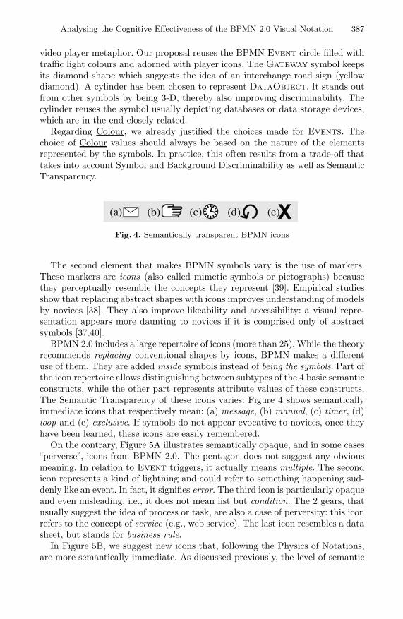
Analysing the Cognitive Effectiveness of the BPMN 2.0 Visual Notation 387
video player metaphor. Our proposal reuses the BPMN Event circle filled withtraffic light colours and adorned with player icons. The Gateway symbol keepsits diamond shape which suggests the idea of an interchange road sign (yellowdiamond). A cylinder has been chosen to represent DataObject. It stands outfrom other symbols by being 3-D, thereby also improving discriminability. Thecylinder reuses the symbol usually depicting databases or data storage devices,which are in the end closely related.
Regarding Colour, we already justified the choices made for Events. Thechoice of Colour values should always be based on the nature of the elementsrepresented by the symbols. In practice, this often results from a trade-off thattakes into account Symbol and Background Discriminability as well as SemanticTransparency.
Fig. 4. Semantically transparent BPMN icons
The second element that makes BPMN symbols vary is the use of markers.These markers are icons (also called mimetic symbols or pictographs) becausethey perceptually resemble the concepts they represent [39]. Empirical studiesshow that replacing abstract shapes with icons improves understanding of modelsby novices [38]. They also improve likeability and accessibility: a visual repre-sentation appears more daunting to novices if it is comprised only of abstractsymbols [37,40].
BPMN 2.0 includes a large repertoire of icons (more than 25). While the theoryrecommends replacing conventional shapes by icons, BPMN makes a differentuse of them. They are added inside symbols instead of being the symbols. Part ofthe icon repertoire allows distinguishing between subtypes of the 4 basic semanticconstructs, while the other part represents attribute values of these constructs.The Semantic Transparency of these icons varies: Figure 4 shows semanticallyimmediate icons that respectively mean: (a) message, (b) manual, (c) timer, (d)loop and (e) exclusive. If symbols do not appear evocative to novices, once theyhave been learned, these icons are easily remembered.
On the contrary, Figure 5A illustrates semantically opaque, and in some cases“perverse”, icons from BPMN 2.0. The pentagon does not suggest any obviousmeaning. In relation to Event triggers, it actually means multiple. The secondicon represents a kind of lightning and could refer to something happening sud-denly like an event. In fact, it signifies error. The third icon is particularly opaqueand even misleading, i.e., it does not mean list but condition. The 2 gears, thatusually suggest the idea of process or task, are also a case of perversity: this iconrefers to the concept of service (e.g., web service). The last icon resembles a datasheet, but stands for business rule.
In Figure 5B, we suggest new icons that, following the Physics of Notations,are more semantically immediate. As discussed previously, the level of semantic

388 N. Genon, P. Heymans, and D. Amyot
transparency depends on several factors and what seems immediate to someonecan remain opaque to somebody else. This suggestion is therefore by no meansdefinitive. The Service icon is a waiter carrying a tray and the Business Ruleicon is now composed of a judge’s hammer (meaning “rule”) filled with a dollarsymbol (meaning“business”). Consequently, and even if they may appear seman-tically perverse at first sight to some people, these icons would probably becomeimmediate for novices as soon as their rationale is explained.
Fig. 5. (A) Semantically opaque icons and (B) More semantically transparent icons
Binary directed relationships are classically represented by arrows that areessentially unidimensional (1-D) visual objects. Therefore, only a small portionof the design space is available to achieve Semantic Transparency. Arrowheadsare a slight incursion in the 2-D world to show direction. Additionally, the sourceanchor of Sequence Flows can be adorned with a Gateway or Defaultmarker (Figure 2B, left). The Gateway marker is rather well chosen whereasthe Default marker is purely conventional. The latter could be removed andthe default flow could be indicated by a larger Grain. This technique is used forpriority road signs, for example. The representation of Data Association (seeFigure 2B, right) is not semantically immediate but this quality seems hard toachieve for this symbol.
3.5 Complexity Management
One of the major flaws of visual notations is their diagrammatic complexity, whichis mainly due to their poor scaling capability [41]. This complexity is measured bythe number of elements displayed on a diagram. The degree of complexity manage-ment varies according to the ability of a notation to represent information withoutoverloading the human mind. The two main solutions to decrease diagrammaticcomplexity are modularisation and hierarchic structuring.
Modularisation consists in dividing complex diagrams into manageable chunks.The decomposition can be horizontal or vertical. While horizontal decompositiontakes place at the same level of abstraction, vertical decomposition produces finergrained sub-diagrams.
BPMN 2.0 provides several mechanisms to manage diagrammatic complexity.First, it supports modelling along 4 different viewpoints that correspond to the4 types of diagrams: Process, Choreography, Collaboration and Con-versation. In a diagram, only the information relevant to the chosen viewpointhas to be represented. BPMN process diagrams achieve modularity thanks to 2constructs (see Figure 6): (a) Link Events are used as intra or inter diagram

Analysing the Cognitive Effectiveness of the BPMN 2.0 Visual Notation 389
connectors. They support horizontal decomposition. A Link Event comes as apair of symbols: a black arrow indicates the source while a white arrow representsthe target. Naming the pairs facilitates their association when there are severalinstances on the same diagram. (b) SubProcesses are self-contained parts ofa process. They allow to vertically decompose a diagram in two levelled views:a high-level view – collapsed subprocess – and a fine-grained view – expandedsubprocess.
Fig. 6. Modularisation with Link Events (example from the BPMN 2.0 spec)
Hierarchic Structuring is one of the most effective ways of organising com-plexity for human comprehension. It allows systems to be represented at differentlevels of detail, with manageable complexity at each level [42]. SubProcessesprovide a means for hierarchic structuring. Yet, to be effective, different levels ofinformation should be displayed in independent diagrams instead of expandinginto their parent diagram (see hierarchical vs. inline expansion in [43]).
3.6 Cognitive Integration
Large system representations cannot fit into a single diagram. The informationis spread across several diagrams and the reader needs to mentally integrateall these pieces of knowledge. Cognitive Integration helps making this integra-tion easier. It takes place at two levels: perceptual integration and conceptualintegration. Perceptual integration refers to cues that simplify navigation andtransitions between diagrams. Conceptual integration addresses the assembly ofinformation from separate diagrams into a coherent mental representation.
While Complexity Management leads to the multiplication of diagrams, notechnique is available in BPMN to reinforce perceptual or conceptual integration.Mechanisms such as diagram level numbering, signposting and navigation maps[44] could improve perceptual integration. Contextualisation information [45,46]and summary diagrams [47] enhance conceptual integration. Concretely, the no-tation should ensure that modellers could name their diagrams and number themaccording to their level in the hierarchic structure. A navigation map couldbe created based on Link Events and SubProcesses. Contextualisation ispartially achieved as expanded SubProcesses are integrated into their parentActivity.

390 N. Genon, P. Heymans, and D. Amyot
3.7 Visual Expressiveness
Visual Expressiveness measures the extent to which the graphic design spaceis used, i.e., the number of visual variables used by a notation and the rangeof values for each variable. While Perceptual Discriminability focuses on pair-wise visual variation between symbols, Visual Expressiveness measures visualvariations across the entire visual vocabulary. Variables that encode informationare called information-carrying variables and compose the primary notation. Theother variables, called the free variables, form the secondary notation [21]. Theyallow modellers to reinforce or clarify the meaning of diagram elements.
Primary Notation. The BPMN process diagram notation uses half of thevisual variables: Location (x,y), Shape, Grain and Colour carry semantic infor-mation, while Size, Orientation and Brightness are relegated to the secondarynotation. Visual variables also have to be chosen according to the type of infor-mation to encode. Figure 7 summarises the power (highest level of measurementthat can be encoded), the capacity (number of perceptible steps), the BPMN val-ues and the saturation (range of values / capacity) of each information-carryingvariable.
Fig. 7. Design space covered by the BPMN process diagram notation
We observe that visual variables in BPMN were chosen appropriately accord-ing to the nature of information, which here is purely nominal (i.e., there is noordering between values). Location can actually be used to encode intervals butit is used in BPMN only for enclosure (a symbol is contained in another symbol),which is only a small portion of its capacity. Visual variable capacities are ratherwell exploited and Grain is even completely saturated. However, as we discussedin Section 3.3, this causes discriminability problems. The perceptible steps be-tween Shape values are a major problem of the current notation. Current shapesbelong to only two categories (circles and quadrilaterals), whereas there is nosemantic relationship between the referent concepts within a shape category. Wehave already illustrated possible solutions to this problem (see Figure 3).
Colour is one of the most cognitively effective of all visual variables. BPMN 2.0specification states that “Graphical elements may be colored, and the coloringmay have specified semantics that extend the information conveyed by the ele-ment as specified in this standard”[1, p. 30]. In fact, BPMN uses only two colours

Analysing the Cognitive Effectiveness of the BPMN 2.0 Visual Notation 391
– black and white – that allow distinguishing between “throwing” (filled) and“catching” (hollow) markers. Hence, the Colour capacity is underused. Improve-ment proposals have been made for this, e.g., the Event symbols in Figure 3.
Secondary Notation consists of the visual variables that do not carry seman-tic information, called free variables. At first sight, secondary notation could bethought of as a low priority matter. However, it proves to be of utmost impor-tance when notation engineers face one of the two following situations. The firstis when there is a need for introducing a new type of information in the language(e.g., if Semiotic Clarity requires a new symbol to be added in the notation). Thelanguage engineer should then first consider free variables before overloading avisual variable that already belongs to the primary notation. This is also thecase if the language engineer wants to achieve redundant coding as describedin Section 3.3. The second situation occurs when modellers need to place visualcues or hints on the diagram to improve its understandability. Most such cuesare cognitive helpers that should be implemented with the secondary notation.The main reason is that they do not carry language information, so they shouldnot compete with existing information-carrying variables.
In practice, cognitive helpers are often defined when designing CASE tools.But CASE tool developers usually implement these helpers differently for eachtool, resulting in non standard solutions even for the same modelling language.To be effective, CASE tools should propose helpers defined by the notation andbased on theory and evidence.
3.8 Dual Coding
So far, text has not been considered as an option for encoding information (seePerceptual Discriminability and Visual Expressiveness). However, this does notmean that text has no place in visual notations. According to Dual Coding the-ory [48], using text and graphics together to convey information is more effectivethan using either on their own. BPMN makes limited use of Dual Coding. It doesso for Conditional and Complex Gateways only. Labels accompany the Al-ternative or Conditional Flows as appearing in Figure 8. Although we didnot observe any major issue with current uses of Dual Coding in BPMN, we sug-gest to further explore the usage of text in order to improve Graphic Economy,which is BPMN’s major problem as discussed in the next section. This contrastswith a recent proposal [49] where Dual Coding is achieved at the expense ofGraphic Economy by adding 25 new iconic markers.
3.9 Graphic Economy
Graphic complexity refers to the size of the visual vocabulary, i.e., the numberof symbols in a notation [50]. It is measured by the number of legend entriesrequired. This differs from diagrammatic complexity as graphic complexity fo-cuses on the language (type level) rather than the diagram (token level). GraphicEconomy seeks to reduce graphic complexity. It is a key factor for cognitive ef-fectiveness since humans’ span of absolute judgement when discriminating visualalternatives is around 6 [51]. It can be higher for experts though.

392 N. Genon, P. Heymans, and D. Amyot
Fig. 8. Dual Coding in BPMN process diagrams
BPMN 2.0 process models have a graphic complexity of 171. This is at leastan order of magnitude beyond novice capabilities (28 times the aforementionedlimit). zur Muehlen and Recker observe that, in practice, the graphic complexityof BPMN is significantly lower than its nominal complexity [26]. Their studyshows that most process diagrams designed for novices use only basic symbols:Event, Activity, Gateway, Sequence Flow, DataObject and Associa-tion, plus a few refinements. The practical complexity is thus around 10. Thisis certainly much more manageable than the full language, but it is still highcompared to popular languages [52] such as ER diagrams (complexity of 5) andDFDs (complexity of 4). YAWL, which is more closely related to BPMN, has acomplexity of 14. Moreover, the question remains open for BPMN experts: dowe really need 171 symbols, even when the goal is to produce detailed modelsfor other experts or for execution in workflow engines? A study similar to that ofzur Muehlen and Recker is necessary for such usage contexts too. It could makethe case for introducing symbol deficit [2], i.e., choosing not to provide symbolsfor some seldom used constructs. Those can still be represented separately usingtext as suggested in Dual Coding, similar to integrity constraints in ER. It mightalso be useful to check BPMN for semantic redundancies that could be factoredout. Such semantic analyses are beyond the scope of this paper, but at the no-tation level it is still possible to improve Perceptual Discriminability, SemanticTransparency and Visual Expressiveness as discussed in the previous sections.
4 Discussion and Conclusions
Defining a cognitively effective notation is a time-consuming activity governed byconflicting goals. As shown in the analysis presented in this paper, BPMN triesto strike a balance between such goals. But we have argued that it does so in asuboptimal way due to its lack of consideration for existing concepts and scientificprinciples of notation design. This first complete analysis4 of BPMN 2.0 againstthe Physics of Notations theory reveals various problems in the BPMN notation,suggests some improvements, but most importantly recommends a change ofmethodology.
Given the effort that this would require, we did not go as far as defining anew notation. Our various suggestions are thus not meant to be definitive orconsistent with each other. Yet, we deem that they have a value in illustrating4 The full analysis is available as a technical report [27].

Analysing the Cognitive Effectiveness of the BPMN 2.0 Visual Notation 393
“outside-of-the-box” thinking about process modelling notations. We hope theywill be regarded as sources of inspiration and debate by the BPM(N) community.
Our analysis (in particular that of Cognitive Fit) also suggests that aiming ata notation that is perfect for all audiences and tasks is utopian. There is no silverbullet. An important question for the future is thus whether there should be oneor multiple dialects of BPMN. Silver [43] seems to support this idea with his3-level methodology for BPM process modelling, using 3 dialects of the BPMNnotation. Empirical studies [26] also suggest to restrict the BPMN symbol setwhen used by novices. But, the quantity of symbols (Graphic Complexity) isonly one of the dimensions to act upon. For example, in a recent similar analysisof the i* goal modelling notation [16], Moody et al. suggested two dialects, one(for hand sketching) being a qualitatively simplified version of the other (forcomputer-based editing).
An obvious limitation of our research (and the Physics of Notations) is thatit focuses only on syntactic issues, whereas solving some of the identified prob-lems (especially the huge number of constructs and symbols) partly requiresre-examining the semantics. Another limitation of our work is the lack of em-pirical validation of our suggestions with real BPMN users. This is mitigatedby the fact that they are based on theory and empirical evidence synthesisedin the Physics of Notations. Moreover, we argue that it would be premature toempirically test these ideas at this stage as they are only our suggestions andare not yet fully developed. More work is needed to explore alternative solutions,preferably with participation from BPMN users and researchers. Finally, we ac-knowledge that there is much legacy related to BPMN as version 1.2 is alreadyused in practice, with support from dozens of commercial tools, some of whichcover additional elements from BPMN 2.0. Our contributions may have a limitedimpact on several legacy symbols but they certainly apply to the numerous newconcepts and symbols found in version 2.0, to future versions of BPMN, and toother related languages.
Acknowledgement. The authors are most thankful to Daniel L. Moody forfruitful discussions. This work was supported in part by the Interuniversity At-traction Poles Programme - Belgian State - Belgian Science Policy (MoVES).NSERC provided funding to D. Amyot in support of this collaboration.
References
1. OMG: Business Process Model and Notation (BPMN) Specification 2.0 V0.9.15.Object Management Group Inc. (2009)
2. Moody, D.L.: The “Physics” of Notations: Towards a Scientific Basis for Construct-ing Visual Notations in Software Engineering. IEEE Transactions on Software En-gineering 35, 756–779 (2009)
3. Larkin, J., Simon, H.: Why a Diagram Is (Sometimes) Worth Ten Thousand Words.Cognitive Science 11, 65–99 (1987)
4. Britton, C., Jones, S.: The Untrained Eye: How Languages for Software Specifica-tion Support Understanding by Untrained Users. Human Computer Interaction 14,191–244 (1999)
394 N. Genon, P. Heymans, and D. Amyot
5. Kosslyn, S.M.: Graphics and Human Information Processing: A Review of FiveBooks. Journal of the American Statistical Association 80(391), 499–512 (1985)
6. Hitchman, S.: The Details of Conceptual Modelling Notations are Important -A Comparison of Relationship Normative Language. Communications of the AIS9(10) (2002)
7. Recker, J., Rosemann, M., Indulska, M., Green, P.: Business Process Modeling- a Comparative Analysis. Journal of the Association for Information Systems(JAIS) 10(4), 333–363 (2009)
8. van der Aalst, W., ter Hofstede, A.: YAWL: Yet Another Workflow Language.Information Systems Journal 30(4), 245–275 (2005)
9. Green, T., Blandford, A., Church, L., Roast, C., Clarke, S.: Cognitive Dimensions:Achievements, New Directions, and Open Questions. Journal of Visual Languagesand Computing 17, 328–365 (2006)
10. Moody, D.L.: Theory Development in Visual Language Research: Beyond the Cog-nitive Dimensions of Notations. In: Proc. of the IEEE Symposium on Visual Lan-guages and Human-Centric Computing (VLHCC 2009), pp. 151–154 (2009)
11. Krogstie, J., Sindre, G., Jorgensen, H.: Process Models Representing Knowledgefor Action: a Revised Quality Framework. European Journal of Information Sys-tems 15, 91–102 (2006)
12. Krogstie, J., Solvberg, A.: Information systems engineering - conceptual modelingin a quality perspective. In: Kompendiumforlaget, Trondheim, Norway (2003)
13. Popper, K.R.: Science as Falsification. In: Routledge, Keagan, P. (eds.) Conjecturesand Refutations, London, pp. 30–39 (1963)
14. Moody, D.L.: Review of archimate: The road to international standardisation. Tech-nical report, Report commissioned by the ArchiMate Foundation and BiZZDesignB.V, Enschede, The Netherlands (2007)
15. Moody, D., van Hillegersberg, J.: Evaluating the visual syntax of UML: An analysisof the cognitive effectiveness of the UML family of diagrams. In: Gasevic, D.,Lammel, R., Van Wyk, E. (eds.) SLE 2008. LNCS, vol. 5452, pp. 16–34. Springer,Heidelberg (2009)
16. Moody, D.L., Heymans, P., Matulevicius, R.: Improving the Effectiveness of VisualRepresentations in Requirements Engineering: An Evaluation of i* Visual Syn-tax (Best Paper Award). In: Proc. of the 17th IEEE International RequirementsEngineering Conference (RE 2009), Washington, DC, USA, pp. 171–180. IEEEComputer Society, Los Alamitos (2009)
17. Genon, N., Amyot, D., Heymans, P.: Analysing the Cognitive Effectiveness of theUCM Visual Notation (to appear, 2010)
18. Bertin, J.: Semiologie graphique: Les diagrammes - Les reseaux - Les cartes.Gauthier-VillarsMouton & Cie (1983)
19. Mendling, J., Reijers, H., van der Aalst, W.: Seven Process Modelling Guidelines(7PMG). Information and Software Technology 52(2), 127–136 (2010)
20. Mendling, J., Reijers, H., Cardoso, J.: What Makes Process Models Understand-able? In: Alonso, G., Dadam, P., Rosemann, M. (eds.) BPM 2007. LNCS, vol. 4714,pp. 48–63. Springer, Heidelberg (2007)
21. Schrepfer, M., Wolf, J., Mendling, J., Reijers, H.: The Impact of Secondary Nota-tion on Process Model Understanding. In: Persson, A., Stirna, J. (eds.) PoEM 2009.Lecture Notes in Business Information Processing, vol. 39, pp. 161–175. Springer,Heidelberg (2009)

Analysing the Cognitive Effectiveness of the BPMN 2.0 Visual Notation 395
22. Figl, K., Mendling, J., Strembeck, M., Recker, J.: On the Cognitive Effectiveness ofRouting Symbols in Process Modeling Languages. In: Abramowicz, W., Tolksdorf,R. (eds.) BIS 2010. Lecture Notes in Business Information Processing, vol. 47, pp.230–241. Springer, Heidelberg (2010)
23. Mendling, J., Recker, J., Reijers, H.A.: On the Usage of Labels and Icons in BusinessProcess Modeling. Computer, 40–58 (2010)
24. Figl, K., Mendling, J., Strembeck, M.: Towards a Usability Assessment of ProcessModeling Languages. In: Proc. of the 8th Workshop Geschaftsprozessmanagementmit Ereignisgesteuerten Prozessketten (EPK 2009), Berlin, Germany. CEUR Work-shop Proceedings, vol. 554, pp. 118–136 (2009)
25. Reijers, H.A., Mendling, J.: Modularity in Process Models: Review and Effects.In: Dumas, M., Reichert, M., Shan, M.-C. (eds.) BPM 2008. LNCS, vol. 5240, pp.20–35. Springer, Heidelberg (2008)
26. Muehlen, M.z., Recker, J.: How Much Language Is Enough? Theoretical and Prac-tical Use of the Business Process Modeling Notation. In: Bellahsene, Z., Leonard,M. (eds.) CAiSE 2008. LNCS, vol. 5074, pp. 465–479. Springer, Heidelberg (2008)
27. Genon, N., Heymans, P., Moody, D.L.: BPMN 2.0 Process Models: Analysis ac-cording to the “Physics” of Notations Principles. Technical report, PReCISE - Uni-versity of Namur (2010),http://www.info.fundp.ac.be/~nge/BPMN/BPMN2_PoN_Analysis.pdf
28. Vessey, I.: Cognitive Fit: A Theory-based Analysis of the Graphs versus TablesLiterature. Decision Sciences 22, 219–240 (1991)
29. Koedinger, K., Anderson, J.: Abstract planning and conceptual chunks: Elementsof expertise in geometry. Cognitive Science 14, 511–550 (1990)
30. Winn, W.: An Account of How Readers Search for Information in Diagrams. Con-temporary Educational Psychology 18, 162–185 (1993)
31. Blankenship, J., Danseraeau, D.F.: The effect of animated node-link displays oninformation recall. The Journal of Experimental Education 68(4), 293–308 (2000)
32. Persson, A.: Enterprise Modelling in Practice: Situational Factors and their Influ-ence on Adopting a Participative Approach. PhD thesis, Department of Computerand Systems Sciences, Stockholm University (2001)
33. Goodman, N.: Languages of Art: An Approach to a Theory of Symbols. Bobbs-Merrill Co., Indianapolis (1968)
34. Winn, W.: Encoding and Retrieval of Information in Maps and Diagrams. IEEETransactions on Professional Communication 33(3), 103–107 (1990)
35. Biederman, I.: Recognition-by-Components: A Theory of Human Image Under-standing. Psychological Review 94(2), 115–147 (1987)
36. Green, D.M., Swets, J.A.: Signal Detection Theory and Psychophysics. Wiley,Chichester (1966)
37. Petre, M.: Why Looking Isn’t Always Seeing: Readership Skills and GraphicalProgramming. Communications of ACM 38(6), 33–44 (1995)
38. Masri, K., Parker, D., Gemino, A.: Using Iconic Graphics in Entity RelationshipDiagrams: The Impact on Understanding. Journal of Database Management 19(3),22–41 (2008)
39. Pierce, C.: The Essential Writings. Prometheus Books (1998)40. Bar, M., Neta, M.: Humans Prefer Curved Visual Object. Psychological
Science 17(8), 645–648 (2006)41. Citrin, W.: Strategic Directions in Visual Languages Research. ACM Computing
Surveys 24(4) (1996)42. Flood, R., Carson, E.: Dealing with Complexity: an Introduction to the Theory
and Application of Systems Science. Plenum Press, New York (1993)

396 N. Genon, P. Heymans, and D. Amyot
43. Silver, B.: BPMN Method and Style. Cody-Cassidy Press (June 2009)44. Lynch, K.: The Image of the City. MIT Press, Cambridge (1960)45. Lamping, J., Rao, R.: The Hyperbolic Browser: a Focus + Context Technique
for Visualizing Large Hierarchies. Journal of Visual Languages and Computing 7,33–55 (1999)
46. Turetken, O., Schuff, D., Sharda, R., Ow, T.: Supporting Systems Analysis andDesign Through Fisheye Views. Communications of ACM 47(9), 72–77 (2004)
47. Kim, J., Hahn, J., Hahn, H.: How Do We Understand a Systeme with (So) ManyDiagrams? Cognitive Integration Processes in Diagrammatic Reasoning. Informa-tion Systems Research 11(3), 284–303 (2000)
48. Paivio, A.: Mental Representations: A Dual Coding Approach. Oxford UniversityPress, Oxford (1986)
49. Mendling, J., Recker, J., Reijers, H.: On the Usage of Labels and Icons in Busi-ness Process Modeling. International Journal of Information System Modeling andDesign, IJISMD (2009)
50. Nordbotten, J., Crosby, M.: The Effect of Graphic Style on Data Model Interpre-tation. Information Systems Journal 9(2), 139–156 (1999)
51. Miller, G.A.: The Magical Number Seven, Plus or Minus Two: Some Limits on OurCapacity for Processing Information. Psycological Review, 81–97 (1956)
52. Davies, I., Green, P., Rosemann, M., Indulska, M., Gallo, S.: How Do PractitionersUse Conceptual Modelling in Practice? Data and Knowledge Engineering 58, 358–380 (2006)

Featherweight TEX and Parser Correctness
Sebastian Thore Erdweg and Klaus Ostermann
University of Marburg, Germany
Abstract. TEX (and its LATEX incarnation) is a widely used documentpreparation system for technical and scientific documents. At the sametime, TEX is also an unusual programming language with a quite powerfulmacro system. Despite the wide range of TEX users (especially in thescientific community), and despite a widely perceived considerable levelof “pain” in using TEX, there is almost no research on TEX. This paperis an attempt to change that.
To this end, we present Featherweight TEX, a formal model of TEXwhich we hope can play a similar role for TEX as Featherweight Java didfor Java. The main technical problem which we study in terms of Feath-erweight TEX is the parsing problem. As for other dynamic languagesperforming syntactic analysis at runtime, the concept of “static” parsingand its correctness is unclear in TEX and shall be clarified in this paper.Moreover, it is the case that parsing TEX is impossible in general, butwe present evidence that parsers for practical subsets exists.
We furthermore outline three immediate applications of our formaliza-tion of TEX and its parsing: a macro debugger, an analysis that detectssyntactic inconsistencies, and a test framework for TEX parsers.
1 Introduction
Almost every user of TEX [7,8] or LATEX [10] is familiar with the technique ofbinary error search: Since TEX error messages often give no hints about thecause of an error (”File ended while scanning use of . . . ”, ”Something’s wrong- perhaps a missing . . . ”), TEX users comment out one half of the code werethe cause is suspected and continue by binary search. The situation gets evenworse when macros are involved, since all errors in macro definitions – includingsimple syntactic errors – only show up when the macro is invoked. Even whenthe error message contains some context information it will be in terms of ex-panded macros with no obvious relation to the cause of the error in the originaldocument. There is no formal grammar or parser for TEX, and consequently nosyntactic analysis which could reveal such errors in a modular way – let alonemore sophisticated analyses such as type checkers.
Errors also often arise since it is not clear to the user how the evaluationmodel of TEX works: When and in which context is a piece of code evaluated?There is no formal specification, but only rather lengthy informal descriptionsin TEX books [4,7]. The TEX reference implementation [8] is much too long andcomplicated to serve as a substitute for a crisp specification.
B. Malloy, S. Staab, and M. van den Brand (Eds.): SLE 2010, LNCS 6563, pp. 397–416, 2011.c© Springer-Verlag Berlin Heidelberg 2011

398 S.T. Erdweg and K. Ostermann
We believe it is a shame that the programming community designs beautifulprogramming languages, analyses, and tools in thousands of papers every year,yet the language which is primarily used to produce these documents is neithervery well understood, nor amenable to modern analyses and tools.
We have developed a formal model (syntax and operational semantics) of TEX,which we call Featherweight TEX, or FTEX for short. FTEX omits all type-settingrelated properties of TEX (which are constituted mostly by a set of a few hundredprimitive commands) and concentrates on the TEX macro system. We hope thatit can have the same fertilizing effect on TEX research that Featherweight Java[6] had for Java.
We use FTEX to study the parsing problem. A parser for TEX would have im-mediate applications such as “static” syntactic error checking, code highlightingor code folding and many other conveniences of modern programming editors,and it would enable the application of other more sophisticated analyses whichtypically require an abstract syntax tree as input. It would also open the door tomigrating thousands of existing TEX libraries to other text preparation systemsor future improved versions of TEX.
To appreciate the parsing problem it is important to understand that in manydynamic languages – general-purpose languages as well as domain-specific lan-guages – parsing and evaluation are deeply intertwined. In this context, it is notclear how a static parser could operate or what a correct parser even is. Dueto the many advantages of static syntactic analyses, the parsing problem is notonly relevant to TEX but to dynamic language engineering in general.
In particular, programs of dynamic languages do not necessarily have a syntaxtree at all. For example, consider the following TEX program:
\def · \app ·#1 ·#2 · {#1 ·#2}\def · \id ·#1 · {#1}\app · a · b\app · \id · c
It defines a macro \app which consumes two arguments, the “identity macro” \id ,and two applications of \app. This program will evaluate to the text a · b · c. Nowconsider the question whether the body of \app, #1 ·#2, is a macro applicationor a text sequence. The example shows that it can be both, depending on thearguments. If the first argument to \app is a macro consuming at least oneargument, then it will be a macro application, otherwise a sequence. Since TEXis a Turing-complete language, the property whether a program has a parse treeis even undecidable.
Our work is based on the hypothesis that most TEX documents do have aparse tree – for example, TEX users will typically not define macros where anargument is sometimes a macro, and sometimes a character. Hence our ultimategoal is to solve the parsing problem for a class of documents that is large enoughfor most practical usages of TEX. To this end, we identify a set of TEX featuresthat are particularly problematic from the perspective of parsing, and presentevidence that many TEX documents do not use these features. As additional

Featherweight TEX and Parser Correctness 399
evidence we define a parser for a subset of TEX in which the absence of theproblematic features is syntactically guaranteed.
We will not present a working parser for unrestricted TEX documents, though.A careful design of a parser will require a more in-depth analysis of typical TEXlibraries and documents, to come up with reasonable heuristics. But even moreimportantly, we believe that the first step in developing a syntactic analysis mustbe to understand exactly what it means for such an analysis to be correct. ForTEX, this is not clear at all. Most languages are designed on top of a context-free grammar, hence the question of correctness does not arise, but since thesemantics of TEX is defined on a flat, unstructured syntax it is not clear what itmeans for a parse tree to be correct. We will formulate correctness of a parse treeas as a correct prediction of the application of reduction rules during programevaluation.
The contributions of this work are as follows:
– We present FTEX, the first formal model of TEX. It is, compared to ex-isting descriptions, rather simple and concise. It can help TEX users andresearchers to better understand TEX evaluation, and it can be the basis formore research on TEX.
– We describe in detail the problem of parsing TEX and formalize a cor-rectness criterion for syntactic analyses. This correctness criterion can notonly be used for formal purposes, but also as a technique to test parserimplementations.
– We identify those features of TEX that are particularly worrisome from theperspective of parsing. We have also evaluated how the TEX macro systemis used in typical LATEX documents by instrumenting a LATEX compiler totrace macro usages. This analysis shows that worst-case scenarios for parsing(such as dynamically changing the arity of a macro) rarely occur in practice.
– We present a working parser for a subset of TEX and verify its correctness.– We show how our formalism can be adapted to form tools relevant in practice.
Amongst others, we outline how a macro debugger can be constructed usingour TEX semantics.
– Since LATEX is just a library on top of TEX, all our results apply to LATEX aswell.
We also believe that our formal model and parsing approaches can be appliedand adopted to other languages that have similar parsing problems, such as Cwith the C preprocessor, or Perl. CPP is agnostic to the grammar of C, hence theC grammar cannot be used to parse such files. Obviously, it would be desirableto have a parser that identifies macro calls and their corresponding arguments.In Perl, like in TEX, parsing and evaluation are intertwined. For example, thesyntactic structure of a Perl function call (foo $arg1, $arg2) may be parsedas either (foo($arg1), $arg2) or foo($arg1, $arg2), depending on whetherfoo currently accepts one or two arguments. In this paper, we will concentrateon TEX, though, and leave the application of our techniques to these languagesfor future work.

400 S.T. Erdweg and K. Ostermann
With regard to related work, to the best of our knowledge this is the first workinvestigating the macro system and parsing problem of TEX (or any aspect ofTEX for that matter). There are some tools that try to parse LATEX code, such aspandoc1 or syntax highlighters in LATEX IDEs such as TEXnicCenter2, but thesetools only work on a fixed quite small subset of LATEX and cannot deal with user-defined macro definitions appropriately. This is also, to our knowledge, the firstwork to define a correctness criterion for syntactic analyses of languages thatmix parsing and evaluation. The main existing related work is in the domain ofparsers for subsets of C with CPP [2,5,11,12,13,14], but none of these works isconcerned with formally (or informally) defining correctness.
The rest of this paper is structured as follows. The next section describeswhy parsing TEX is hard. Section 3 presents our TEX formalization, FTEX. Sec-tion 4 defines parser correctness by means of a conformance relation betweensyntax trees and parsing constraints generated during program evaluation. InSection 5 we explain the difficulties of parsing TEX in terms of our formalizationand demonstrate that provably correct parsers exist for reasonably large subsetsof TEX. Our empirical study of TEX and LATEX macro usage is presented in Sec-tion 6. Section 7 discusses the applicability of our techniques to everyday TEXprogramming. Section 8 concludes.
2 Problem Statement
TEX has a number of properties that make parsing particularly challenging. First,TEX macros are dynamically scoped: A macro call is resolved to the last macrodefinition of that name which was encountered, which is not necessarily the onein the lexical scope of the macro call. This means that the target of a macro callcannot be statically determined, which is a problem for parsing since the actualmacro definition determines how the call is parsed. For example, whether a isan argument to \foo in the macro call \foo · a depends on the current definitionof \foo.
Second, macros in TEX can be passed as arguments to other macros. Thisinduces the same problem as dynamic scoping: Targets of macro calls can ingeneral not be determined statically.
Third, TEX has a lexical [3] macro system. This means that macro bodiesor arguments to macros are not necessarily syntactically correct3 pieces of TEXcode. For example, a macro body may expand to an incomplete call of anothermacro, and the code following the original macro invocation may then completethis macro call. Similarly, macros may expand to new (potentially partial) macrodefinitions.
Fourth, TEX allows a custom macro call syntax through delimited parame-ters. Macro invocations are then “pattern-matched” against these delimiters. Forexample, the TEX program1 http://johnmacfarlane.net/pandoc/2 http://www.texniccenter.org3 We do not know yet what syntactic correctness for TEX means anyway.

Featherweight TEX and Parser Correctness 401
\def · \foo ·#1 · d ·#2 · {#1 · x · y ·#2}\foo · a · b · c · d · e
will evaluate to a · b · c · x · y · e. Such delimiters can be used by TEX librariesto effectively define new domain-specific syntax. For example, using the qtree4
library for drawing trees, the command
\Tree [. Delimiter syntax [.is [.a ] pain ] ]
results in the following tree:Delimiter
syntax is
a painThere are two other parsing-related properties of TEX which, however, we willnot be concerned with in this paper, namely category codes and TEX primitives.During the evaluation of a TEX program, a mapping of characters to categorycodes is maintained. For example, the category code 0 describes escape charac-ters, which is usually only the backslash \. In principle, it is possible to changethe category code mapping while evaluating a TEX program, but to our knowl-edge this happens very rarely outside the “bootstrapping” libraries, so we donot expect this to be a big problem in practice. It is in any case a problem thatcan be dealt with separately from the problem we are dealing with here.
TEX primitives are also relevant for parsing, because they can change theargument evaluation in a way that cannot be expressed using macros. Most no-tably, the \expandafter and \futurelet commands affect the evaluation order ofprograms. The former temporarily skips ahead of the expression following it,while the latter constitutes a lookahead mechanism. Furthermore, with TEX’svarious kinds of variables come a multitude of special-syntax assignment primi-tives, and alignments need their own special treatment anyway [4,7]. Still, thereseems to be no conceptual hurdle for our main goal, that is the development ofa correct syntactic analysis for a feature-rich subset of TEX, and we believe thatthe formal model presented next captures the most interesting and challengingaspects of TEX for parsing.
3 Featherweight TEX
We have formalized the core of the TEX macro system – in particular the as-pects described in the previous section – in the form of a small-step operationalsemantics. We call this language FTEX and present its syntax in Fig. 1.
In FTEX, a program s consists of five primitive forms, namely characters c,macro identifiers m, macro parameters x, groups {s}, and the macro definitioncommand \def . We call these forms expressions. In addition, let ♦ represent theempty expression, which is not allowed to occur in user programs. Expressions arecomposed by sequentialization only, i.e. there is no syntactic distinction between4 http://www.ling.upenn.edu/advice/latex/qtree/

402 S.T. Erdweg and K. Ostermann
c ∈ character charactersm ∈ M macro variablesx ::= #1 | . . . | #9 | #x macro parameterse ::= c | m | x | {s} | \def | ♦ expressionss ::= e FTEX programs
σ ::= {x �→ s} substitutionsr ::= c | x | m | ♦ parameter tokens
dM ::= \def ·M · r · {s} macro valuesv ::= ε | c · v | dM · v | ♦ · v values
RM ::= [ ] | c ·RM | dM ·RM reduction contexts| ♦ · RM | {RM} | RM · e
Fig. 1. FTEX syntax
macro calls and the concatenation of text, see definition of s. Since this syntaxdoes not identify the structure of macro applications, we call s the flat syntax.We do not restrict the use of the macro definition command to syntacticallyvalid macro definitions (such as md ::= \def · m · x · {s}) since in TEX macrodefinitions may be computed dynamically by the expansion of other macros. Forexample, one could define a macro \def ′ which behaves exactly like \def but, say,adds an additional dummy argument to the macro.
The operational semantics of FTEX, Fig. 2 is defined in a variant of the eval-uation context style from Wright and Felleisen [16]. This means that, instead ofintroducing environments and similar entities, every relevant runtime entity isencoded within the language’s syntax. The necessary additional (runtime) syn-tax and evaluation contexts are defined below the FTEX syntax in Fig. 1. It isimportant to note that the forms d and R are parametrized over the set of macrovariables M ⊆M that may occur in definitions.
dropDefs : v → vdropDefs(ε) = εdropDefs(c · v) = c · dropDefs(v)dropDefs(d · v) = ♦ · dropDefs(v)dropDefs(♦ · v) = ♦ · dropDefs(v)
σ : s→ sσ(x) = σ(x)σ({s}) = {σ(s)}σ(e) = eσ(ε) = εσ(e · e) = σ(e) · σ(e)
s→ s′
RM[s]→ RM[s′](R-RStep) {v} → dropDefs(v)
(R-GVal)
match(r, s′) = σ
\def ·m · r · {s} · RM\{m}[m · s′]→ \def ·m · r · {s} · RM\{m}[σ(s)]
(R-Macro)
Fig. 2. FTEX reduction semantics

Featherweight TEX and Parser Correctness 403
The reduction system has only three rules: A congruence rule (R-RStep) whichallows the reduction inside a context, a reduction rule (R-GVal) to eliminategroups that are already fully evaluated, and a rule (R-Macro) for evaluating macroapplications.
(R-RStep) is standard for every evaluation-context based semantics. For (R-GVal),it is important to understand that macro definitions inside a group are notvisible outside the group, hence there is actually a mix of static and dynamicscoping. Within a fixed nesting level, scoping is dynamic, i.e., the rightmostdefinition of the macro wins, as long as it is on the same or a lower nesting level,but definitions in deeper nesting levels are ignored. For this reason it is safe todiscard all macro definitions in fully evaluated groups and just retain the textcontained in it - which is exactly what dropDefs does.
Not surprisingly, the (R-Macro) rule for evaluating macro calls is the mostsophisticated one. The evaluation context RM\{m} is used to make sure that themacro definition of m is indeed the right-most one on the same or lower nestinglevel by prohibiting further definitions of m. (R-Macro) uses the parameter text rand the macro arguments s′ to compute a substitution σ, which is then appliedto the macro body s.5 Substitution application σ is not hygienic [9], capture-avoiding or the like; rather, it just replaces every occurrence of a variable by itssubstitute.
The match function is used for matching actual macro arguments with theparameter text, i.e., the part between the macro name and the macro body,which may potentially contain delimiters of the form c or m in addition to themacro parameters; see the syntax of r. match expects the parameter text asits first argument and the argument text as its second one. It then generates asubstitution σ, mapping macro parameters x to FTEX terms s.
Due to space limitations we cannot display the full definition of match here,but instead present a few examples in Fig. 3. The first two calls of match accordto usual parameter instantiation, where in the first one the argument’s groupis unpacked. Delimiter matching is illustrated by the subsequent three calls. Inparticular, the fifth example shows that delimited variables may instantiate tothe empty expression. The last example fails because only delimited parameterscan consume sequences of arguments; the second character is not matched bythe parameter.
match(x, {c1 · c2} ) = {x �→ c1 · c2}match(x1 · x2, c1 · c2 ) = {x1 �→ c1, x2 �→ c2}match(c1 · c2, c1 · c2 ) = {}match(x · c4, c1 · c2 · c3 · c4 ) = {x �→ c1 · c2 · c3}match(x · c, c ) = {x �→ ♦}match(x, c1 · c2 ) = undefined
Fig. 3. Examples of Matching
5 Here and in the remainder of this paper, we use a = a1 · · · an to denote a sequenceof a’s and ε to denote the empty sequence.

404 S.T. Erdweg and K. Ostermann
In summary, macros are expanded by first determining their active definitionusing parametrized reduction contexts, then matching the parameter text againstthe supplied argument text, and finally applying the resulting substitution to themacro body, which replaces the macro call.
4 Correctness of Syntactic Analyses
Given an unstructured representation of a program, syntactic analyses try toinfer its structured representation, that is a syntax tree. A syntax tree is a pro-gram representation in which program fragments are composed according to thesyntactic forms they inhabit. In FTEX, there are three compositional syntac-tic forms, namely macro application, macro definition and sequentialization, seeFig. 4. Macro applications t@ t consist of a macro representation and the pos-sibly empty list of arguments. The definition of a macro is represented by thesequence of program fragments forming the definition 〈t〉. The sequentializationof two trees t ; t is used to denote sequential execution and result concatenation.
f ::= c | m | x | {t} | \def tree expressionst ::= ∅ | f | t ; t | t @ t | 〈 t 〉 syntax treest⊥ ::= ⊥ | t parse result
Fig. 4. Tree syntax
An FTEX parser thus is a total function p : s → t⊥ assigning either a syntaxtree or ⊥ to each program in s (see Fig. 1 for the definition of s). However, noteach such function is a valid parser; the resulting syntax trees must represent theoriginal code and its structure correctly. But what characterizes a correct struc-tural representation? Looking at syntax trees from another angle helps answerthis question.
Syntax trees can also be understood to predict a program’s run in that theevaluation needs to follow the structure specified by the tree. More precisely,if we assume the language’s semantics to be syntax-directed, the syntax tree’sinner nodes restrict the set of applicable rules to those matching the respectivesyntactic form. By inversion, the reduction rules used to evaluate a programconstrain the set of valid syntax trees. For instance, in a program which isreduced by macro expansion, the macro and its arguments must be related bya macro application node in the syntax tree. A value, on the other hand, mustcorrespond to a sequence of macro definitions and characters.
Accordingly, a correct FTEX parser is a total function p : s → t⊥ such that(i) each syntax tree represents the original code and (ii) each tree is compatiblewith the reduction rules chosen in the program’s run.
In the present section, we formalize these requirements, i.e. we give a formalspecification of correct syntax trees and parsers. Often, however, one wants asyntax tree to be compatible not only with the specific program run generatedby evaluating the represented program; rather, syntax trees should be modular,
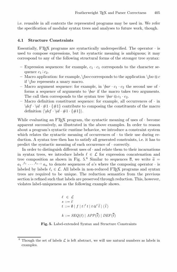
Featherweight TEX and Parser Correctness 405
i.e. reusable in all contexts the represented programs may be used in. We referthe specification of modular syntax trees and analyses to future work, though.
4.1 Structure Constraints
Essentially, FTEX programs are syntactically underspecified. The operator · isused to compose expressions, but its syntactic meaning is ambiguous; it maycorrespond to any of the following structural forms of the stronger tree syntax:
– Expression sequences: for example, c1 · c1 corresponds to the character se-quence c1 ; c2.
– Macro application: for example,\foo·ccorresponds to the application \foo @ cif \foo represents a unary macro.
– Macro argument sequence: for example, in \bar · c1 · c2 the second use of ·forms a sequence of arguments to \bar if the macro takes two arguments.The call then corresponds to the syntax tree \bar @ c1 · c2.
– Macro definition constituent sequence: for example, all occurrences of · in\def · \id ·#1 · {#1} contribute to composing the constituents of the macrodefinition 〈\def · \id ·#1 · {#1}〉.
While evaluating an FTEX program, the syntactic meaning of uses of · becomeapparent successively, as illustrated in the above examples. In order to reasonabout a program’s syntactic runtime behavior, we introduce a constraint systemwhich relates the syntactic meaning of occurrences of · to their use during re-duction. A syntax tree then has to satisfy all generated constraints, i.e. it has topredict the syntactic meaning of each occurrence of · correctly.
In order to distinguish different uses of · and relate them to their incarnationsin syntax trees, we introduce labels � ∈ L for expression concatenation andtree composition as shown in Fig. 5.6 Similar to sequences a, we write a =a1 ·�1 · · · ·�n−1 an to denote sequences of a’s where the composing operator · islabeled by labels �i ∈ L. All labels in non-reduced FTEX programs and syntaxtrees are required to be unique. The reduction semantics from the previoussection is refined such that labels are preserved through reduction. This, however,violates label-uniqueness as the following example shows.
� ∈ Ls ::= e
t ::= ∅ | f | t ;� t | t@� t | 〈 t 〉
k ::= SEQ(�) | APP(�) | DEF (�)
Fig. 5. Label-extended Syntax and Structure Constraints
6 Though the set of labels L is left abstract, we will use natural numbers as labels inexamples.

406 S.T. Erdweg and K. Ostermann
Example 1\def ·1 \seq ·2 #1 ·3 #2 ·4 {#1 ·5 #2} ·6 \seq ·7 c1 ·8 c2
→ \def ·1 \seq ·2 #1 ·3 #2 ·4 {#1 ·5 #2} ·6 c1 ·5 c2
In this example, a macro \seq taking two arguments is defined. In the macrobody the two arguments are composed by the operator labeled 5. Since labelsare preserved through reduction, label 5 occurs outside the macro body afterexpanding \seq, namely in the body’s instantiation c1 ·5 c2.
When only regarding the uninstantiated macro body of \seq there is no way oftelling how the macro arguments are combined, i.e. which syntactic meaning theoperator labeled 5 inhabits. Depending on the actual first argument the operatorcould, for instance, denote a macro application or the construction of a macrodefinition. In the above example, however, the macro expands into a composi-tion of characters, hence the operator has to represent the sequentialization ofexpressions.
More generally, labels fulfill two purposes. First, they enable the identificationof conflicts: if, for instance, a macro is called several times and expands intoconflicting syntactical forms, such as sequentialization and application, therewill be conflicting requirements on the involved labels. The respective operatorsthus have to have several syntactic meanings during runtime, which rules out astatic syntactic model. Second, by using the same labels in FTEX programs andsyntax trees, the structural prediction made by a parser can be easily related tothe program’s structure during runtime.
Our formulation of syntax tree correctness relies on the notion of structureconstraints k, Fig. 5, which restrict the syntactic meaning of labeled compositionoperators. SEQ(�) requires that ·� represents an expression sequentialization,APP(�1 · · · �n) denotes that ·�1 is a macro application composition and ·�2 · · · ·�n
forms a sequence of macro argument. Since, macro argument sequentializationalways is accompanied by a macro application, only one form of constraint isneeded. Lastly, constraints of the form DEF (�1 · · · �n) demand that the labeledoperators ·�1 · · · ·�n represent the composition of macro definition constituents.
To see these constraints in action, reconsider Ex. 1. As we will show inthe subsequent subsection, all of the following constraints can be derived byevaluation:
DEF (1 · 2 · 3 · 4), SEQ(5), SEQ(6) APP(7 · 8)
4.2 Constraint Generation
The syntactic relations between different parts of a program emerge during eval-uation. To this end, we instrument the previously presented reduction semanticsto generate structure constraints as the syntactic meanings of compositions ·become apparent.
The adapted reduction semantics is shown in Fig. 6. For a reduction steps
K−→ s′, K denotes the set of generated constraints. Accordingly, the reductionrule (R-RStep) simply forwards the constraints generated for the reduction of the

Featherweight TEX and Parser Correctness 407
subexpression s. When applying (R-GVal), it is exploited that the group containsa value only, i.e. that it contains a sequence of macro definitions and characters.The corresponding structure constraints are generated by applying valcons tothat value.
valcons : v → {k}valcons(ε) = ∅valcons(c) = ∅valcons(d) = {DEF (�1 · · · �n)},
where d = e1 ·�1 · · · ·�n en+1
valcons(c ·� v) = {SEQ(�)} ∪ valcons(v)
valcons(d ·� v) = valcons(d) ∪ {SEQ(�)} ∪ valcons(v)valcons(♦ ·� v) = {SEQ(�)} ∪ valcons(v)
sK−→s′
RM[s]K−→RM[s′]
(R-RStep)
{v} valcons(v)−−−−−−→dropDefs(v)(R-GVal)
\def ·�1 m ·�2 {s} ·�3 RM\{m}[m]∅−→\def ·�1 m ·�2 {s} ·�3 RM\{m}[σ(s)]
(R-MacroEps)
match(r, e) = σ
e = e1 ·�′1 · · · ·�′n en+1
k = APP(�′ · �′1 · · · �′n)
\def ·�1 m ·�2 r ·�3 {s} ·�4 RM\{m}[m ·�′e]
{k}−−→\def ·�1 m ·�2 r ·�3 {s} ·�4 RM\{m}[σ(s)]
(R-Macro)
Fig. 6. Constraint Generation
Macro expansion is split into two rules. The first one, (R-MacroEps), coversthe expansion of macros that have no parameters (note the lack of r in themacro definition). In this case no syntactical structure is exploited and thus noconstraints are generated. The second macro expansion rule, (R-Macro), generatesa single constraint which denotes the applicative structure of the expanded macrocall.
Constraint generation now can be summarized as follows.
Definition 1. The set of constraints Ω(s →∗ s′) associated to the reductionsequence s→∗ s′ of the program s is defined by:
Ω(v) = valcons(v)Ω(s) = ∅, if s = v for all v
Ω(s K−→s′ →∗ s′′) = K ∪Ω(s′ →∗ s′′)
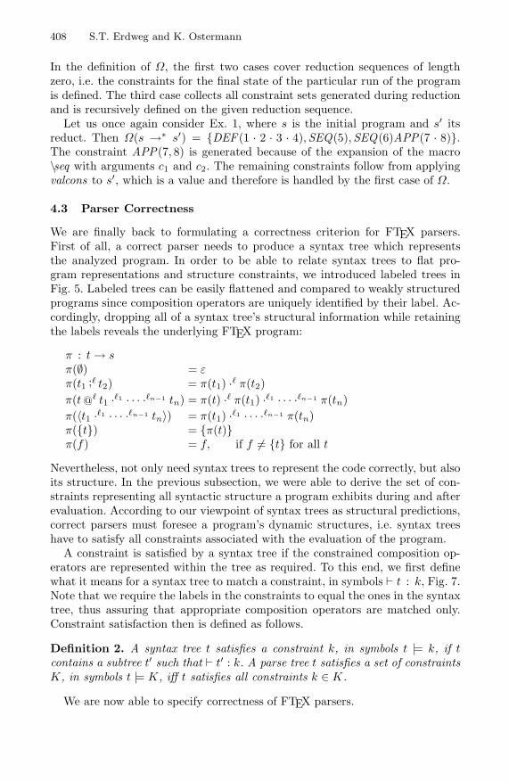
408 S.T. Erdweg and K. Ostermann
In the definition of Ω, the first two cases cover reduction sequences of lengthzero, i.e. the constraints for the final state of the particular run of the programis defined. The third case collects all constraint sets generated during reductionand is recursively defined on the given reduction sequence.
Let us once again consider Ex. 1, where s is the initial program and s′ itsreduct. Then Ω(s →∗ s′) = {DEF (1 · 2 · 3 · 4),SEQ(5),SEQ(6)APP(7 · 8)}.The constraint APP(7, 8) is generated because of the expansion of the macro\seq with arguments c1 and c2. The remaining constraints follow from applyingvalcons to s′, which is a value and therefore is handled by the first case of Ω.
4.3 Parser Correctness
We are finally back to formulating a correctness criterion for FTEX parsers.First of all, a correct parser needs to produce a syntax tree which representsthe analyzed program. In order to be able to relate syntax trees to flat pro-gram representations and structure constraints, we introduced labeled trees inFig. 5. Labeled trees can be easily flattened and compared to weakly structuredprograms since composition operators are uniquely identified by their label. Ac-cordingly, dropping all of a syntax tree’s structural information while retainingthe labels reveals the underlying FTEX program:
π : t→ sπ(∅) = επ(t1 ;� t2) = π(t1) ·� π(t2)π(t @� t1 ·�1 · · · ·�n−1 tn) = π(t) ·� π(t1) ·�1 · · · ·�n−1 π(tn)π(〈t1 ·�1 · · · ·�n−1 tn〉) = π(t1) ·�1 · · · ·�n−1 π(tn)π({t}) = {π(t)}π(f) = f, if f = {t} for all t
Nevertheless, not only need syntax trees to represent the code correctly, but alsoits structure. In the previous subsection, we were able to derive the set of con-straints representing all syntactic structure a program exhibits during and afterevaluation. According to our viewpoint of syntax trees as structural predictions,correct parsers must foresee a program’s dynamic structures, i.e. syntax treeshave to satisfy all constraints associated with the evaluation of the program.
A constraint is satisfied by a syntax tree if the constrained composition op-erators are represented within the tree as required. To this end, we first definewhat it means for a syntax tree to match a constraint, in symbols � t : k, Fig. 7.Note that we require the labels in the constraints to equal the ones in the syntaxtree, thus assuring that appropriate composition operators are matched only.Constraint satisfaction then is defined as follows.
Definition 2. A syntax tree t satisfies a constraint k, in symbols t |= k, if tcontains a subtree t′ such that � t′ : k. A parse tree t satisfies a set of constraintsK, in symbols t |= K, iff t satisfies all constraints k ∈ K.
We are now able to specify correctness of FTEX parsers.

Featherweight TEX and Parser Correctness 409
� t1 ;� t2 : SEQ(�)(K-Seq) � t @
� t1 ·�1 · · · ·�n tn+1 : APP(� · �1 · · · �n)(K-App)
� 〈t1 ·�1 · · · ·�n tn+1〉 : DEF (�1 · · · �n)(K-Def)
Fig. 7. Constraint matching
Definition 3. A total function p : s→ t⊥ is a correct FTEX parser if and onlyif for all FTEX programs s with p(s) = ⊥1. π(p(s)) = s, and2. for all programs s′ with s→∗ s′, p(s) |= Ω(s→∗ s′).
A syntactic analysis for FTEX thus is correct if the resulting syntax trees areproper representations and structural predictions of original programs.
5 Towards Parsing TEX
In the previous section, we presented a formal specification of correct FTEXparsers. Accordingly, syntax trees computed by correct parsers must satisfy allstructure constraints emerging during the evaluation of the analyzed program.For some programs, however, the set of generated structure constraints is in-herently unsatisfiable, that is, inconsistent: the constraints place contradictingrequirements on syntax trees.
In the present section we show that these inconsistencies arise from the prob-lematic language features of TEX we discussed in Section 2. We furthermoredemonstrate that by restricting the language such that the problematic featuresare excluded, we are able to define a provably correct parser for that subset.
5.1 Parsing-Contrary Language Features
When language features allow syntactic ambiguities they actually hindersyntactic analyses. For TEX, these ambiguities translate into the generation ofinconsistent structure constraints, because ambiguous expression can be usedinconsistently. Here we present an example for each such language feature andshow that it entails inconsistent constraints. For brevity, we only denote thoselabels in the examples that are used for discussion.
Dynamic scoping. In TEX, parsing a macro application depends on the appliedmacro’s actual definition. It matters whether the macro expects one or two argu-ments, for example, because then either the following one or two characters, say,are matched. With dynamic scoping the meaning of a macro variable dependson the dynamic scope it is expanded in. Therefore, one and the same macrovariable can exhibit different syntactic properties:

410 S.T. Erdweg and K. Ostermann
\def · \foo · {c}\def · \bar · {\foo ·1 c}\bar\def · \foo ·#1 · {c}\bar
Here, each of the calls to \bar reduces to \foo ·1c. In the former call, however, \foois defined as a constant, i.e. it does not expect any argument. Therefore, the for-mer expansion of \bar implies the structure constraint SEQ(1). Contrarily, whenexpanding the second call to \bar , \foo is bound to expect one argument. There-fore, the expansion of \bar corresponds to a macro call of \foo with argument c,and hence the constraint APP(1) is generated.
In a lexically scoped language, the expansion of \bar would consist of a closurethat binds all free variables in the macro body. The macro identifier \foo thuswould refer to the definition \def · \foo · {c} in both expansions of \bar .
Higher-order arguments. Similarly to macro identifiers in dynamic scoping,higher-order arguments lead to syntactically ambiguous interpretations of macroparameters. Depending on the actual argument, a parameter may represent aconstant expression or in turn a macro.
In the following we define two macros, both of which take two arguments. Theformer one builds the sequence of its parameters while the second applies thefirst parameter to the second parameter.
\def · \seq ·#1 ·#2 · {#1 ·1 #2}\def · \app ·#1 ·#2 · {#1 ·#2}
Evidently, the only difference between the definitions of \seq and \app are theirnames. The macro body’s syntactic structure thus only depends on whether ornot the first argument is a constant or expects further input. When calling \seqwith two characters, say, the call expands to a sequence of these characters andthe constraint SEQ(1) is generated. In contrast, when calling \seq with a unarymacro and a character, it will expand into yet another macro call. In this casethe conflicting constraint APP(1) is generated.
Lexical macro system. In contrast to syntactical macro systems [15], macros inTEX are lexical, that is, macro arguments and bodies do not necessarily corre-spond to complete syntax trees.\def · \foo · {\def ·1 \baz}\def · \bar ·#1 · {\foo ·2 #1 ·3 {c}}
In this example neither dynamic scoping nor higher-order macros is relevant.Still, the structure of \bar ’s body is ambiguous and depends on the argument#1. The call \bar · c′, for example, expands to \def ·1 \baz ·2 c′ ·3 {c} in two steps.Correspondingly, the structure constraint DEF (1, 2, 3) is generated. On the otherhand, if \bar is called as in \bar · {{c′}}, it expands to \def ·1 \baz ·2 {c′} ·3 {c},thus the constraints DEF (1, 2) and SEQ(3) are generated.

Featherweight TEX and Parser Correctness 411
Furthermore, the body of \foo cannot be correctly represented by any syntaxtree, because it does not inhibit a valid syntactical form. This is the intrinsicdifficulty in performing syntax analyses on top of a lexical transformation systemsuch as TEX.
Custom macro call syntax. TEX users are allowed to define their own macrocall syntax as desired. For instance, the following macro needs to be called withparentheses.\def · \foo · ( ·#1 · ) ·{c}
This, however, easily leads to ambiguities when the call syntax depends on macroparameters, i.e. when a macro argument is matched against the call pattern.\def · \bar ·#1 · {\foo ·1 ( ·2#1 ·3 )}\bar · c\bar · )
Here, the call to \foo in the body of \bar depends on the macro parameter #1.While the first call to \bar entails the constraint APP(1, 2, 3) as expected, thesecond call expands to \foo ·1 ( ·2 ) ·3 ). Consequently, the constraints APP(1 · 2)and SEQ(3) are generated, and establish an inconsistency with the first expan-sion of \bar .
5.2 Parsing FTEX Correctly
We just identified some sources of syntactic ambiguities in FTEX, and can nowfocus on finding an actually parsable subset of the language. To this end, wepresent a non-trivial FTEX parser and prove it correct with respect to Def. 3.
First, let us fix the set of programs our parser p will be able to parse, i.e. forwhich p results in an actual syntax tree. These programs are subject to thefollowing restrictions:
1. All macro definitions are complete, unary, top-level and prohibit custom callsyntax, that is, they strictly follow the syntactic description \def ·� m ·� #1 ·�{s} and occur non-nestedly.
2. All uses of macro variables (except in macro definitions) are directly followedby a grouped expression, as in m ·� {s}. Since all macros are unary, thegrouped expression will correspond to the macro’s argument which thus canbe statically identified.
3. All macros are first-order, i.e. their argument is not a macro itself. To thisend, we require all occurrences of macro parameters in macro bodies to bewrapped in groups. A higher-order argument would thus always be capturedby a group, as in {\foo}. This would lead to a runtime error since the contentof a group must normalize to a value.
The complete parser pi is defined in Fig. 8. p0 accounts for the top-level pro-grams which may contain definitions. Nested program fragments are parsed byp1 where definitions are prohibited but wrapped macro parameters are allowed.

412 S.T. Erdweg and K. Ostermann
pi(ε) = ∅pi(c ·� s) = c ;� pi(s)
pi(m ·�1 {s} ·�2 s′) = (m @�1{p1(s)}) ;�2 pi(s
′)pi({s} ·� s′) = {p1(s)} ;� pi(s
′)pi(♦ ·� s) = ∅ ;� pi(s)p0(\def ·�1 m ·�2 #1 ·�3 {s} ·�4 s′) = 〈\def ·�1 m ·�2 x ·�3 {p1(s)}〉 ;�4 p0(s
′)p1({#1} ·� s) = {x} ;� p1(s)pi(s) = ⊥
Fig. 8. A provably correct FTEX parser
The definition of pi is to be read such that in each case the parser also returns⊥ if any nested call returns ⊥.
In order to verify the correctness of p0 with respect to Def. 3, we need toshow that the resulting syntax trees represent the input programs and satisfyall structure constraints associated to runs of the programs.
Theorem 1. For all programs s with pi(s) = ⊥, π(pi(s)) = s for i ∈ {0, 1}.
Lemma 1. For all values v, pi(v) |= valcons(v) for i ∈ {0, 1}.
Lemma 2. For i ∈ {0, 1} and all programs s and s′ with sK−→s′ and pi(s) = ⊥
(i) pi(s) |= K,(ii) pi(s′) = ⊥, and(iii) {k | pi(s) |= k} ⊇ {k | pi(s′) |= k}.
Proof. By case distinction on the applied reduction rule.
(i) By Lem. 1 and inversion on p0 and p1.(ii) For (R-Macro) this holds since macro bodies are p1-parsable and p1-pars-
ability is closed under substitution. The other cases are simple.(iii) For (R-Macro) let R = \def ·�1m·�2#1·�3{sb}·�4RM\{m}[] with R[m·�′{sa}] =
s, R[σ(sb)] = s′ and σ = {#1 �→ sa}. Then {k | p(R[m ·�′ {sa}]) |= k} ⊇{k | p(R[ ]) |= k ∨ p(sa) |= k} ⊇ {k | p(R[σ(sb)]) |= k}. The other casesare simple.
Theorem 2. For i ∈ {0, 1} and all FTEX programs s and s′ with s →∗ s′, ifpi(s) = ⊥ then pi(s) |= Ω(s→∗ s′).
Proof. By induction on the reduction sequence s →∗ s′. For s = v by Lem. 1.For s in normal form and s = v, Ω(s) = ∅. For s
K−→s′ →∗ s′′ by Lem. 2 and theinduction hypothesis.
Corollary 1. p0 is a correct FTEX parser.

Featherweight TEX and Parser Correctness 413
6 Macro Usage in TEX and LATEX
In the previous section, we demonstrated how our formal specification of FTEXparsers can be instantiated to give a provably correct parser. The subset ofFTEX the parser supports was designed to avoid all of the pitfalls described inSection 5.1. Parsers which support larger subsets of FTEX do exist, though, andin the present section we set out to justify their relevance in practice.
Identifying a sublanguage of TEX which is broad enough to include a widerange of programs used in practice and, at the same time, is precise enough toinclude a considerably large parsable subset, is a task involving a detailed studyof existing TEX and LATEX libraries as well as conflict-resolving heuristics, whichexclude some programs in favor of others. Nonetheless, we believe that signifi-cantly large portions of the existing TEX and LATEX libraries in fact are parsable,i.e. not exposed to the issues associated with dynamic scoping, delimiter syntaxand macro arguments consuming further input. This claim is supported by astudy of macro usage in existing TEX and LATEX libraries, Fig. 9, which we havebeen carrying out.
Macro definitions
total 345823 ∼ 100.0%
constant 320357 ∼ 92.6%
recursive 56553 ∼ 16.4%
delimiter syntax 12427 ∼ 3.6%
redefinitions 160697 ∼ 46.5%
redef. arity changes 16289 ∼ 4.7%
– ignoring macros “*temp*” 7175 ∼ 2.1%
redef. delimiter syntax changes 16927 ∼ 4.9%
– ignoring macros “*temp*” 5827 ∼ 1.7%
Macro expansions
total 2649553 ∼ 100.0%
constant 746889 ∼ 28.2%
recursive 524320 ∼ 19.8%
delimiter syntax 95512 ∼ 3.6%higher-order arguments 70579 ∼ 2.7%
Fig. 9. Macro usage in TEX and LATEX libraries
To collect various statistics about macro definitions and applications, weadapted a Java implementation of TEX, called the New Typesetting System [1].7
Our adaption is available at http://www.informatik.uni-marburg.de/~seba/texstats. We analyzed 15 LATEX documents originating from our research groupand ranging from research papers to master’s theses. These documents amount
7 This implementation is incomplete with respect to the typesetting of documents,but complete regarding TEX’s macro facilities.

414 S.T. Erdweg and K. Ostermann
to 301 pages of scientific writing and contain more than 300,000 macro defini-tions and 2,500,000 macro expansions. The high number of macro definitions,which might be surprising, is mainly caused by the use of libraries, e.g. amsmath.
Our analysis observes facts about the sample documents’ uses of macro defi-nitions and macro applications. To this end, a macro is considered constant if itsdefinition has no declared parameter. A macro is called recursive if the transitivehull of macro identifiers used in its body contains the macro’s own identifier.8
Since the assumed recursive call not necessarily is executed, a macro may beconsidered recursive without actually being so. A macro has a delimited syntaxif the parameter text in its definition contains characters or macro identifiers.A macro is redefined if a definition for the same macro identifier has previouslybeen executed. A redefinition changes the arity of a macro, if the number ofparameters in the previously executed definition differs. Similarly, the delimitersyntax of a macro is changed by its redefinition if the previously executed def-inition’s parameter text contains different characters or macro identifiers, or adifferent order thereof. Additionally, arity and delimiter syntax changes havebeen recorded for macro identifiers not containing the string “temp”. Lastly, amacro is said to be applied with higher-order arguments if at least on argumentis a non-constant macro.
In the tables of Fig. 9, we state the absolute number of occurrences of theobserved effects and their percentage relative to the respective category’s totalnumber of effects.
Our study shows that only 3.6% of all macro definitions and expansions usedelimiter syntax. Furthermore, only 4.7% of all macro definitions correspond toredefinitions changing the redefined macro’s arity, and 4.9% correspond to re-definitions changing its delimiter syntax. Nonetheless, most of these definitionsredefine a macro with the string “temp” in its name. This gives reason to be-lieve that the different versions of these macros are used in unrelated parts ofthe program, and do not entail conflicting constraints. Moreover, higher-orderarguments are used only in 2.7% of all analyzed expansions.
The high number of redefinitions and constant macro definitions, 46.5% and92.6%, is also interesting. This is in contrast to the number of expansions ofparameterless macros, which is only 28.2%. We believe that this effect can beexplained by the frequent usage of constant macros as variables, as opposed tobehavioral abstractions. Accordingly, a redefinition of a constant macro occurswhenever the stored value has to change. This technique is often used for con-figuring libraries. For example, the LLNCS document class for this conferencecontains the macro redefinition
\renewcommand \labelitemi {\ normalfont \bfseries --}
which is used in the environment itemize and controls the label of items in top-level lists. Any change of this parameter is a macro redefinition. Such macro re-definitions cause no problems for parsing, since the protocol and parsing-relatedbehavior of the macro does not change.8 For parsing, it is unimportant whether a macro is recursive. We included this prop-
erty anyway because we found it an interesting figure nonetheless.
Featherweight TEX and Parser Correctness 415
The presented data suggests that despite dynamic scoping, delimiter syntaxand higher-order arguments, the syntactical behavior of macros often can bestatically determined, because these language features, which are particularlytroublesome for parsing, are rarely used. Therefore, we believe that the develop-ment of a practical syntactic analysis for TEX and LATEX is possible.
7 Applications
Besides giving a precise formulation of parser correctness, our formal model hasvaluable, immediate applications in practice. In the following we propose threetools easing the everyday development with TEX and LATEX.
Macro debugging. Our formal FTEX semantics is defined in form of a small-step operational reduction semantics. Consequently, it allows single stepping ofmacro expansions and FTEX processing. This support is of high potential benefitfor TEX users since it enables comprehending and debugging even complicatedmacro libraries.
In order to apply macro stepping meaningfully to only part of a TEX document,the context in which the code is evaluated has to be fixed. One promising possibil-ity is to scan the document for top-level library imports and macro definitions, andreduce the code in the context of those definitions. Similar techniques are alreadyapplied in some TEX editors, however not for the purpose of debugging.
Syntactic inconsistency detection. In Section 4.2, we introduced constraint gen-eration which denotes the dynamic syntactical structure of FTEX code. Con-straint generation cannot be used in static analyses, though, because it impliesevaluating the program. In a programming tool, however, gathering structuralinformation by running the program is a valid approach. Therefore, the in-strumented FTEX semantics can be used to generate and identify conflictingstructure constraints, which indicate accidental syntactic inconsistencies in theanalyzed program and should be reported to the programmer.
Parser testing. Almost all TEX editors contain a rudimentary parser for TEXdocuments, so that syntax highlighting, for example, is possible. Often enough,however, these simplistic parsers produce erroneous syntax trees, essentially dis-abling all tool support. By taking advantage of constraint generation again, theparser can actually be tested. As stated in the definition of parser correctness,all generated constraints need to be satisfied by resulting syntax trees. The TEXeditor can thus check whether its parser is correctly predicting the document’sstructure, and deliberately handle cases where it is not.
More generally, all generated constraints can be understood as test cases foruser defined FTEX parsers. To this end, the constraint generator and the con-straint satisfaction relation comprise a framework for testing FTEX parsers.
8 Conclusion
We have defined a formal model of TEX and have clarified formally what itmeans for a static parser to be correct. We have identified language features that

416 S.T. Erdweg and K. Ostermann
are hindering syntactic analyses and have shown that provably correct parsersexist for subsets of TEX that exclude such features. Furthermore, we have givenempirical evidence that this class of practical interest. We have also demonstratedhow TEX programmers may benefit from our formal model in their everydaywork, for instance by using a macro debugger.
We hope that this work will trigger a new line of research that will result in abroad range of tools for TEX users and, eventually, in a new design of TEX andLATEX according to modern programming language design principles which willremove the idiosyncrasies that today’s TEX users have to suffer.
Acknowledgments. This work was supported in part by the European Re-search Council, grant #203099.
References
1. NTS: A New Typesetting System, http://nts.tug.org/ (visited on 20.03.2010)2. Badros, G.J., Notkin, D.: A Framework for Preprocessor-Aware C Source Code
Analyses. Software: Practice and Experience 30(8), 907–924 (2000)3. Brabrand, C., Schwartzbach, M.I.: Growing Languages with Metamorphic Syntax
Macros. In: Partial Evaluation and Semantics-Based Program Manipulation, pp.31–40. ACM, New York (2002)
4. Eijkhout,V.:TEXbyTopic,ATEXnicansReference.Addison-Wesley,Reading (1992)5. Garrido, A., Johnson, R.: Refactoring C with Conditional Compilation. In: Auto-
mated Software Engineering, pp. 323–326. IEEE Computer Society, Los Alamitos(2003)
6. Igarashi, A., Pierce, B., Wadler, P.: Featherweight Java - A Minimal Core Calculusfor Java and GJ. ACM Transactions on Programming Languages and Systems,132–146 (1999)
7. Knuth, D.E.: The TEXbook. Addison-Wesley, Reading (1984)8. Knuth, D.E.: TEX: The Program. Addison-Wesley, Reading (1986)9. Kohlbecker, E.E., Friedman, D.P., Felleisen, M., Duba, B.F.: Hygienic Macro Ex-
pansion. In: LISP and Functional Programming, pp. 151–161. ACM, New York(1986)
10. Lamport, L.: LATEX: A Document Preparation System. Addison-Wesley, Reading(1986)
11. Latendresse, M.: Rewrite Systems for Symbolic Evaluation of C-like Preprocessing.In: European Conference on Software Maintenance and Reengineering, pp. 165–173. IEEE Computer Society, Los Alamitos (2004)
12. Livadas, P.E., Small, D.T.: Understanding Code Containing PreprocessorConstructs. In: Program Comprehension, pp. 89–97. IEEE Comp. Society, LosAlamitos (1994)
13. Padioleau, Y.: Parsing C/C++ Code without Pre-processing. In: de Moor, O.,Schwartzbach, M.I. (eds.) CC 2009. LNCS, vol. 5501, pp. 109–125. Springer,Heidelberg (2009)
14. Saebjoernsen, A., Jiang, L., Quinlan, D.J., Su, Z.: Static Validation of C Prepro-cessor Macros. In: Automated Software Engineering, pp. 149–160. IEEE ComputerSociety, Los Alamitos (2009)
15. Weise, D., Crew, R.: Programmable Syntax Macros. In: Programming LanguageDesign and Implementation, pp. 156–165. ACM, New York (1993)
16. Wright, A.K., Felleisen, M.: A Syntactic Approach to Type Soundness. Informationand Computation 115(1), 38–94 (1994)

Author Index
Aßmann, Uwe 22Amaral, Vasco 296Amyot, Daniel 377Atkinson, Colin 266
B ↪ak, Kacper 102Bandener, Nils 357Barroca, Bruno 296Bernstein, Abraham 203Boucher, Quentin 337Braatz, Benjamin 82Brandt, Christoph 82Burger, Christoff 22
Cadiz, Alfredo 246Cardozo, Nicolas 246Cicchetti, Antonio 183Czarnecki, Krzysztof 102
Dechev, Damian 123Di Ruscio, Davide 143, 183
Engels, Gregor 357Eramo, Romina 183Erdweg, Sebastian Thore 397Erwig, Martin 1
Favre, Jean-Marie 316Felix, Roberto 296
Gasevic, Dragan 316Genon, Nicolas 377Goß, Bjorn 266Goffaux, Julien 246Gonzalez, Sebastian 246
Hartmann, Herman 337Hedin, Gorel 2Herrmannsdoerfer, Markus 62, 163, 286Heymans, Patrick 337, 377Høst, Einar W. 226Hubaux, Arnaud 337
Johnstone, Adrian 42, 306
Kalleberg, Karl T. 327Karol, Sven 22Kats, Lennart C.L. 327Kennel, Bastian 266Koegel, Maximilian 62
Lammel, Ralf 143, 206, 316Libbrecht, Jean-Christophe 246Lucio, Levi 296
Mannadiar, Raphael 276Mens, Kim 246Michel, Raphael 337
Østvold, Bjarte M. 226Ostermann, Klaus 397
Pek, Ekaterina 316Pierantonio, Alfonso 143, 183Pirkelbauer, Peter 123
Ratiu, Daniel 62
Scott, Elizabeth 42, 306Soderberg, Emma 2Soltenborn, Christian 357Sousa, Vasco 296Stroustrup, Bjarne 123
Vangheluwe, Hans 276Vermolen, Sander D. 163Visser, Eelco 327
Wachsmuth, Guido 163W ↪asowski, Andrzej 102Wende, Christian 22
Zaytsev, Vadim 206


![Kittler-Etal1998 [My Paper as Reference]](https://static.fdocuments.in/doc/165x107/577d23821a28ab4e1e99fed8/kittler-etal1998-my-paper-as-reference.jpg)