Lecture Notes - iare.ac.in · efficiency of thermal rockets in the atmosphere, pulse detonation...
79
Page 1 of 79 Lecture Notes Aerospace Propulsion II III rd B.Tech II nd Semester Department of Aeronautical Engineering Prepared by C.Satya Sandeep Assistant Professor Department of Aeronautical Engineering
Transcript of Lecture Notes - iare.ac.in · efficiency of thermal rockets in the atmosphere, pulse detonation...

Page 1 of 79
Lecture Notes Aerospace Propulsion II
IIIrd B.Tech IInd Semester
Department of Aeronautical Engineering
Prepared by
C.Satya Sandeep Assistant Professor
Department of Aeronautical Engineering
Page 2 of 79
Aerospace Propulsion II
UNIT – 1
Trans-Atmospheric and Space Flight Mission Propulsion Requirements- Propulsion Systems-
Classification, Performance Characteristics: Hypersonic transport vehicles, military missiles,
space launch vehicles, spacecraft- role, types, missions- profile, trajectories, operating
conditions- gravity, atmosphere. Incremental flight velocity budget for the climb out and
acceleration, orbital injection- Breguet equation for the cruise- mission propulsion requirements-
thrust levels, burning time, economy.
High-speed propulsion systems- types, construction, operating principles- sources of energy,
generation of power, momentum, propellants- applications, performance parameters- specific
thrust, specific impulse, internal efficiency, propulsive efficiency- typical values. Reaction
control systems- applications.
UNIT – 2
Air Breathing Engines for Hypersonic Transport Planes and Military missiles – Supersonic
Combustion – The Scram-Jet Engine: Performance of turbojets, ramjets at high speeds-
limitations, Need for supersonic combustion- implications- criticality of efficient diffusion and
acceleration, problems of combustion in the high-speed flow. The scramjet engine –
construction, flow process- description, control volume analysis- spill over drag, plume drag.
Component performance analysis- isolator, combustor- flow detachment and reattachment,
thermal throat, scheduled, distributed fuel injection. Nozzle flow, losses- failure to
recombination, viscous losses, plume losses. Scramjet performance, applications.
Combined cycle engines- turbo-ramjet, air turbo-rocket (ATR), ejector ramjet- Liquid-air
collection engine (LACE) – need, principle, construction, operation, performance, applications to
hypersonic transport plane and missile propulsion.
UNIT – 3
Chemical Rocket Engines: Rocket propulsion – history, principles, types, applications. The
rocket equation. Vehicle velocity, jet exit velocity, mass ratio. Effect of the atmosphere. Engine
parameters, propellants.

Page 3 of 79
Chemical rocket- the thrust chamber- processes- combustion, expansion- propellants.
Thermochemical analysis of combustion, equilibrium energy balance, mass balance, combustion
efficiency. Equilibrium composition, recombination. Nozzle expansion, performance, design
parameters, analysis- non-equilibrium expansion- frozen equilibrium, shifting equilibrium. One
dimensional, two-dimensional flows, the presence of liquid drops and solid particles- two-phase
flow, losses, efficiency.
A performance measure of chemical rocket engines- thrust coefficient, specific impulse; engine
parameters- thrust chamber pressure, temperature, characteristic velocity, exhaust velocity,
effective velocity. Computing rocket engine performance- theoretical, delivered performance,
performance at standard operating conditions, guaranteed minimum performance
UNIT – 4
Liquid Propellant Rocket Engines, Solid Propellant Rocket Motors: Liquid propellant rocket
engines- structure- principal components, basic parameters- propellant combination, chamber
pressure, nozzle area ratio, feed system, thrust level, Propellants – properties- considerations for
selection- storage, feed, control, injection, ignition. Combustion chamber and nozzle, shape, size
materials, cooling – thrust vector control, combustion instabilities. Engine control, optimization,
system integration. Liquid propellant rocket performance data.
Solid propellant rocket motors- basic configuration, essential differences from liquid propellant
rocket engines, propellant composition, combustion chambers, ignition surface recession rate,
gas generation rate, the effect of propellant temperature, combustion pressure, charge design-
thrust profile, burning stability, erosive burning. Combustion chamber integrity- thermal
protection. Combustion instabilities- types, corrective measure. Solid propellant motor
components and motor design. Applications, performance analysis. Examples of solid propellant
boosters. Hybrid propellant rockets, selection of rocket propulsion systems.
Advanced thermal rockets- fundamental physical limitation of thermal rockets, improving the
efficiency of thermal rockets in the atmosphere, pulse detonation engine, rotary rocket engine,
variable exhaust velocity, Particulars of propulsion systems of selected space vehicles and
military missiles.
UNIT – 5
Page 4 of 79
Electric Thrusters- Mission Applications of Space Flight: Limitations of chemical rocket
engines. Electric propulsion systems- structure, types, generation of thrust. System parameters-
interrelations. Electrothermal thrusters- resistor jet, arc jet, solar/laser/microwave thermal
propulsion- operating principles, components, system parameters, performance, applications.
Electrostatic thrusters- ionization potential, ionization schemes. Beam current, power,
acceleration, voltage, power efficiency, thrust-to-power ratio, specific impulse. Screen,
accelerator grids, potential, charge distribution, saturated current density, electric field intensity,
exhaust neutralization, propellant choice. Estimation of performance, electrical efficiency, the
power to thrust ratio, thrust per unit area, applications.
Electromagnetic thrusters- magneto plasma dynamic (MPD), pulsed plasma (PPT), Hall Effect
and variable Isp thrusters- principle, construction, operation, performance, applications. Electric
space power supplies and power conditioning- batteries, fuel cells, solar cell arrays, solar
generators, nuclear power generators. Current technology of electric propulsion engines,
applications- and overview. The problem of gravity loss. Criteria for selection of engine.
Particulars of select current electric propulsion systems.
TEXTBOOKS
1. Sutton, G.P., and Biblarz, O., Rocket Propulsion Elements, 7th edn. Wiley, 2001, ISBN: 0-
471- 32642-9.
2. Hill, P.G., and Peterson, C.R., Mechanics, and Thermodynamics of Propulsion, 2nd
edn. Addison Wesley, 1992.
3. Kerrebrock, J.L., Aircraft Engines and Gas Turbines, 2nd edn. , MIT Press, 1992, ISBN: 0-
262- 11162-4.
4. Turner, M.J.L., Rocket and Spacecraft Propulsion, 2nd edn. Springer, 2005, ISBN: 3 540-
22190.
5. Tajmar, M., Advanced Space Propulsion Systems, Springer, 2003, ISBN: 3-211-83862-7.
REFERENCES
1. Jensen, G.E., and Netzer, D.W., ed. Tactical Missile Propulsion, AIAA, 1996, ISBN 1-
56347-118-3.
2. NASA JPL Advanced Propulsion Concepts Notebook

Page 5 of 79
UNIT I
TRANS-ATMOSPHERIC AND SPACE FLIGHT MISSION PROPULSION
REQUIREMENTS PROPULSION SYSTEMS- CLASSIFICATION, PERFORMANCE
CHARACTERISTICS
Basic sciences involved in the field of propulsion are:
1. Laws Of motion: are associated with the motion of Aircraft which is the important thing
in this course
2. Laws of Thermodynamics: the creation of Motion and the propulsion systems are
based conceptually on the laws of thermodynamics. Thermodynamics is the matrix on
which the entire field of Propulsion is concentrated on. So we need to know a lot about
thermodynamics which will be covered by Prof. Pradeep.
3. Principles and theories of Aerodynamics: Prof Pradeep will be covering the
Aerodynamics. We need to know Aerodynamics because a lot of Prolusion we deal in
this course is based on Aerodynamics. Various Aerodynamics Laws, Principles &
Mathematics need to be known. Many of the components of Propulsion or Propulsive
Devices works on the principles of Aerodynamics and many of them are called
Aerodynamics Machines. So many of the propulsive devices are known as Aero-
Thermodynamics Devices. So we need to know both these sciences very well.
4. Mechanical Sciences: Deals with the mechanical Issues and a lot of Mechanical
engineering in making propulsive devices and engines which basically are Mechanical
Entities.
5. Material Sciences: Issues related to Material and Metallurgical Sciences are dealt here.
The propulsive devices use the Material Sciences of the highest order.
6. Control Theory: Most of the devices of Aircraft Propulsion and Rocket Propulsion need
to be controlled. These theories are extremely involved and they are the sciences by
themselves. Some of the issues of Control of the propulsive devices will be dealt here.
These propulsive devices need to be embedded with the modern control theories and
control systems.
MOTION:

Page 6 of 79
The propulsive devices that are created are trying to impart a continuous motion to the aircraft or
spacecraft and not just a motion for a few seconds. Its continuous motion that is required, so
some fundamental sciences are required to apply to these Propulsive Devices which govern the
motion of various bodies. Newton’s laws of Motion codified various concepts of creating
continuous motion and these motions are what we are concerned about in this course. Before
Newton’s Laws of Motions came into being, the concept of creating motion through various kind
of understanding of motion was actually applied. For example: paddling the oars to make the
boats move in water uses an instinctive understanding of basic principles without the application
of the laws of motion. The question of understanding the motion has been there for more than
thousands of years and Newton codified those laws in the form of Physics or Mathematical Laws
and making it easy for us to create propulsive devices using the sciences and laws.
TYPES OF MOTIONS:
Perpetual Motion: It is not physically possible but it has been possible because of the various
laws of Physics and Mathematics that have existed and they have proved that it’s not really
possible to create Perpetual Devices. We have to have devices that create motion on a continuous
basis. A motion cannot be sustained on a continuous basis but a device has to be created that on a
continuous basis of producing perpetual motion. In our case, it deals with the creation of
Perpetual motion. And this continuous production of force is what is necessary we have to
provide through the propulsive devices. This course deals with whether a continuous force can
be provided for continuous flying motion.
Some of the earlier methods that used to provide continuous forces for providing continuous
motion started some 2000 years back.
1. One of the devices that were developed was Aeolipile designed by Hero in 2nd
century BC. He
demonstrated a particular device in which if steam is put in and allow the steam to come out
through Jets in Opposite Direction, then the continuous motion can be created of a ball. This
ball can be held on together on both sides which can provide a rolling motion to the ball. This
was called Aeolipile. About 1800 years after this, William Avery designed this Ball which is
shown in the picture on the right side. During the time of Hero, there was no Newton’s Law to
develop this idea. Hero developed this Aeolipile based on his instinctive understanding.

Page 7 of 79
2. Around 13th
Century, the Chinese Scholar Wan Hu decided to try and create a Flying Motion.
Since China is very good at making Gun Powder and Fireworks, they had the concept of
making small rockets through the Fireworks could be made to fly. Wan Hu as a scholar
thought was that if a number of rockets were put together and fired them up together, then the
object could be made to fly. He made a chair which consisted of a number of rockets attached
to the under of the chair and fired them up together so that a vertical flying motion was
produced. It was one of the first attempts to make human being go up in the air in the 13th
century. But we do not know if that story is true because the picture shown is an artist’s
drawing.
3. The next invention was from Leonardo Da Vinci, who is regarded as the genius of the
millennium. Around 16th
century he created what is now known as a Chimney Jack, which
the hot air rising up from the chimney creates a motion of the turbine and this rotating turbine
was used to drive a number of elements like Gear Box, Belt and Pulley Drive and other
motions. He used the hot gas of a chimney to make a Turbine. This was one of the first
methods developed conceptually to make a turbine through the hot gas or hot air.
Subsequently around that Wind Turbines were being created around the world which used
the natural air to rotate the Turbine. However, the most important contribution of Leonardo
Da Vinci was the Ornithopter which is a machine that actually could make human beings
fly. His idea was to create a small platform in which the human being can sit or lie down and
it would have something like a Helicopter which will have a Vertical Motion similar to a
Screw Motion and the whole device would rise up in the air using the Screw Motion of the
air. This was his concept of Ornithopter which he never made but was only conceptualized
by him. Da Vinci also created the Flapping Wing concept which is actually a copy of the
motion of Birds Flying. Da Vinci thought if we could imitate the Mechanical Motion of the
Birds Flying then human beings could also fly like birds. He noticed as an avid scientist and
as an engineer that flapping wing contributes to the flying motion of the birds. So he created
a small conceptual machine in which he thought could have flapping wings which if could be
flapped could aid the motion of this craft. The Picture shown represents Da Vinci’s
Page 8 of 79
Ornithopter. Whether the machine was made is not sure. As a concept, nothing was wrong
with it and today lot of people talk about the flapping wing concept as one of the modern aids
of making a new aircraft or a small aircraft.
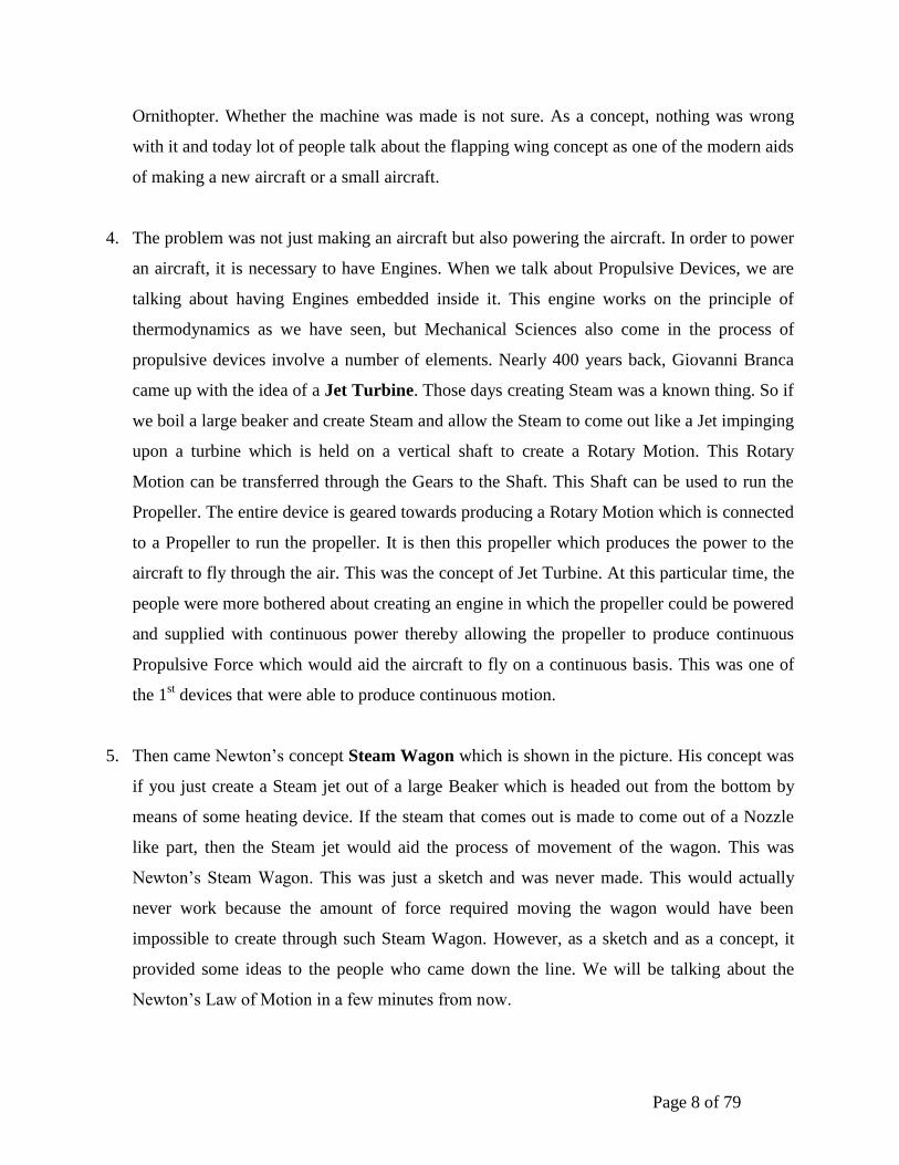
4. The problem was not just making an aircraft but also powering the aircraft. In order to power
an aircraft, it is necessary to have Engines. When we talk about Propulsive Devices, we are
talking about having Engines embedded inside it. This engine works on the principle of
thermodynamics as we have seen, but Mechanical Sciences also come in the process of
propulsive devices involve a number of elements. Nearly 400 years back, Giovanni Branca
came up with the idea of a Jet Turbine. Those days creating Steam was a known thing. So if
we boil a large beaker and create Steam and allow the Steam to come out like a Jet impinging
upon a turbine which is held on a vertical shaft to create a Rotary Motion. This Rotary
Motion can be transferred through the Gears to the Shaft. This Shaft can be used to run the
Propeller. The entire device is geared towards producing a Rotary Motion which is connected
to a Propeller to run the propeller. It is then this propeller which produces the power to the
aircraft to fly through the air. This was the concept of Jet Turbine. At this particular time, the
people were more bothered about creating an engine in which the propeller could be powered
and supplied with continuous power thereby allowing the propeller to produce continuous
Propulsive Force which would aid the aircraft to fly on a continuous basis. This was one of
the 1st devices that were able to produce continuous motion.
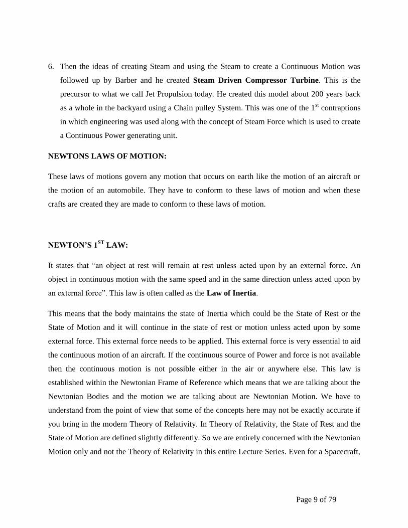
5. Then came Newton’s concept Steam Wagon which is shown in the picture. His concept was
if you just create a Steam jet out of a large Beaker which is headed out from the bottom by
means of some heating device. If the steam that comes out is made to come out of a Nozzle
like part, then the Steam jet would aid the process of movement of the wagon. This was
Newton’s Steam Wagon. This was just a sketch and was never made. This would actually
never work because the amount of force required moving the wagon would have been
impossible to create through such Steam Wagon. However, as a sketch and as a concept, it
provided some ideas to the people who came down the line. We will be talking about the
Newton’s Law of Motion in a few minutes from now.
Page 9 of 79
6. Then the ideas of creating Steam and using the Steam to create a Continuous Motion was
followed up by Barber and he created Steam Driven Compressor Turbine. This is the
precursor to what we call Jet Propulsion today. He created this model about 200 years back
as a whole in the backyard using a Chain pulley System. This was one of the 1st contraptions
in which engineering was used along with the concept of Steam Force which is used to create
a Continuous Power generating unit.
NEWTONS LAWS OF MOTION:
These laws of motions govern any motion that occurs on earth like the motion of an aircraft or
the motion of an automobile. They have to conform to these laws of motion and when these
crafts are created they are made to conform to these laws of motion.
NEWTON’S 1ST
LAW:
It states that “an object at rest will remain at rest unless acted upon by an external force. An
object in continuous motion with the same speed and in the same direction unless acted upon by
an external force”. This law is often called as the Law of Inertia.
This means that the body maintains the state of Inertia which could be the State of Rest or the
State of Motion and it will continue in the state of rest or motion unless acted upon by some
external force. This external force needs to be applied. This external force is very essential to aid
the continuous motion of an aircraft. If the continuous source of Power and force is not available
then the continuous motion is not possible either in the air or anywhere else. This law is
established within the Newtonian Frame of Reference which means that we are talking about the
Newtonian Bodies and the motion we are talking about are Newtonian Motion. We have to
understand from the point of view that some of the concepts here may not be exactly accurate if
you bring in the modern Theory of Relativity. In Theory of Relativity, the State of Rest and the
State of Motion are defined slightly differently. So we are entirely concerned with the Newtonian
Motion only and not the Theory of Relativity in this entire Lecture Series. Even for a Spacecraft,
Page 10 of 79
we will not be talking about the motion of a body using Theory of Relativity as a law of Physics.
We will always be in the Newtonian Frame of Reference.
NEWTON’S 2ND
LAW:
It states that “acceleration is produced when the force acts on a mass. The greater the mass of the
object being accelerated the greater the amount of Force needed to accelerate the object”.
Creation of the motion is itself a kind of acceleration. When you are starting from a state of rest,
you need some force and that itself is a first acceleration that you need to produce and it is
codified simply as:
F = M*A
Where,
M- Rest mass (definition of Rest mass is different from Newtonian Mechanics to the Relativity
theory)
So this mass to be accelerated needs a force and this is what the 2nd
law motion states. Our work
in Propulsion is to create this Force such that the motion can be created.
NEWTON’S 3RD
LAW:
It states that “for every action, there is an equal and opposite re-action”.
This law is very well known for all the laws and this is the important law on which the
propulsive system is based on. This law tells that if you create an action then there is bound to be
an equal and opposite re-action. As the diagram illustrates, if an action is created to push a body
then some amount of material is ejected from the rear which the diagram illustrates. The act of
releasing the material from the rear is the Action and the reaction is the force that propels the
body forward. This is the concept on which most of the Aircraft and the spacecraft is based on.
This action of releasing some material from the rear of the body which we want to move is the 1st
principle on which the propulsive devices are created on. Newton’s 3rd
law serves as one of the
bases on which the propulsive devices are created. This was developed conceptually long back.
Page 11 of 79
For example:
Shown in the picture, if you fill an up balloon and then hold the balloon in one hand and take
your hand off and release the compressed air or pressured air from within the balloon to suddenly
come out through the open lip, then it will create a nozzle as we saw in the illustration of the 3rd
law. This nozzle effect will immediately create a Re-action. So the Action created by the release
of air from inside through the open lip creates a force and that Re-action makes the balloon move
forward. If you do this experiment by yourselves in a room, you will find that the balloon is
moving in a Zigzag motion. This is not because anything has gone wrong with the balloon or the
release of the balloon. The point is the balloon is always moving as a re-action to the action
instantaneously through that lip. So the instantaneous Re-action direction and the magnitude
creates the instantaneous motion of the balloon. So the Zigzag motion you see is the correct
Motion based on the instantaneous vector of the action that is created. Re-action always occurs
opposite to that vector.
This is shown in the lower diagram in the Aircraft example. If you are flying an aircraft and if
you create an Action which throws something towards the back and this something we shall see
more and more is actually the air in which the aircraft is supposed to be flying. If you create an
action of throwing the Air actually backward then the aircraft experiences the Re-action which is
the motion forward. Our work in this course is to see how this action can be created through
various devices on a Continuous basis in a Controlled Manner so that in a controlled manner we
have the reaction and motion of the aircraft. We cannot allow the aircraft to move in a Zigzag
manner as we see in the balloon. We have to have a continuous, controlled, smooth motion of
the aircraft and this smooth motion of the aircraft needs to be done in a controlled manner. This
controlled Action and Re-action needs to be created through the Propulsive Devices and there is
a question of integration of these propulsive devices with the aircraft. We shall be talking about
more and more issues relating to this as we enter into the subject matter.
NEWTON’S 1ST
LAW:
Let’s get into Newton’s 1st law in detail because that is what is going to create the bedrock for
our Subject.

Page 12 of 79
It states that “if the vector sum of all forces acting on the object is zero then the velocity of the
object is constant”. This means that if the object is in a state of rest it will be in its state of rest
and if the object is in its state of motion then it will remain in its state of motion without
experiencing any change in its motion. There will be no acceleration, no change in velocity
and no change in direction. For changing any one of the three mentioned previously, you
would need to apply force and this force will need to be applied in a certain direction. So the
Vector Sum of all the forces is what we need to have our eyes on so that the motion can be
created in a particular direction giving it a particular magnitude.
So the creation of Motion is the 1st thing in Newton’s law and giving it a direction is a next thing.
We need to keep our eyes open on both the issues that are creating the motion, the magnitude of
the force we apply and the direction in which the force is applied because the Re-action will be
based on both the magnitude and the direction of the action that is created. The reaction will be
opposite to that magnitude and direction.
NEWTON’S 2ND
LAW:
The second law states that “the net force on a body is equal to the time rate of change of its linear
momentum M in a specified reference of the frame for the inertial motion under interest”.
The second law is mathematically codified as:
For a constant mass system, we get,
Where,
M- Linear Momentum in a particular direction.

Page 13 of 79
m – Rest mass
V- Instantaneous velocity
The 3rd
equation above constitutes what we call as Force is the product of mass (m) and
acceleration (derivative term) that was written down earlier. This signifies that for moving a
certain body of mass (m), a certain amount of acceleration is to be given which produces a
Linear Momentum change thereby creating the Force of Action and the Re-action is the motion
of the aircraft forward.
Any mass that is gained or lost by the system will cause a change in momentum. That is not
because of the external force. A different equation is necessary for Variable-Mass Systems.
This is the issue one has to talk about. The mass that we considered earlier was a fixed mass. If
we have a Variable Mass System (eg): Spacecraft when the mass stored in the spacecraft is used
and the mass changes with respect to time. So finally the mass flow will be different for a
variable mass system and the equation of Newton’s Law will also be different for a Variable
Mass System. Most of the time we will be dealing with the constant mass system, but if the
variable mass system is used then necessary equations are to be used.
Consistent with the Law I, the time derivative of the momentum is non-zero when the
momentum changes direction, even if there is no change in the magnitude. This motion is
associated with the Circular Motion. This happens because the Instantaneous Velocity of the
motion is always constant, but it is continuously changing its direction. This direction change
requires a continuous application of an External Force. This is what is done when an aircraft or a
Spacecraft is taken a turn on its flight which may be either circular or non-circular. But the forces
are to be applied to bring this change in Direction. The propulsive devices are needed to bring a
change in the direction of action so that the reaction force makes the craft to change its direction.
This implies the Conservation of Momentum. When the net force on the body is zero, the
momentum of the body is constant (zero or non-zero). The Net force is therefore equal to the
Rate of Change of the Momentum assuming there is no loss of energy anywhere. This is the
fundamental principle on which the action-reaction works and this is what is required when we
create the propulsive devices.
Page 14 of 79
The concept of Propulsive Forces of Flying Vehicles:
Newton’s 2nd
Law is the conceptual basis of the Propulsive Forces of all Flying Vehicles.
Newton’s 2nd
law is the law that is activated more inside the Propulsive Device to create all the
motions and the physics involved in creating the propulsive force. At very high speeds, the
concept that the momentum is the product of Rest Mass and Velocity is not accurate because we
are talking about the motion of an object around the speed of light according to the theory of
Relativity. These motions are not considered for the creation of the propulsive device. We will
be dealing with the propulsive devices that depend on the Newton’s Laws, Newtonian Fluid, and
Newton’s motion.
Impulse:
Impulse is the corollary of the force. It is defined as the force that acts over an interval of a small
time it and is given by,
This type of Impulsive force makes the Rockets, missiles and Space Vehicles move through
Space.
NEWTON’S 3RD
LAW:
It states that “all forces are interactions between different bodies and thus there is no such thing
as a unidirectional force or a force that acts on only one body”.
The law states that every force has a Counter Force. The reaction force is very much important
because it is the force that makes the craft move. If a body A exerts a force on body B, body B
simultaneously exerts a force of the same magnitude on body A then both the forces will be
acting on the same line. This represents the action-reaction concept of Newton’s 3rd
Law.
Page 15 of 79
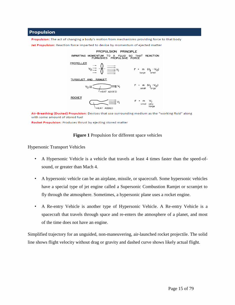
Figure 1 Propulsion for different space vehicles
Hypersonic Transport Vehicles
• A Hypersonic Vehicle is a vehicle that travels at least 4 times faster than the speed-of-
sound, or greater than Mach 4.
• A hypersonic vehicle can be an airplane, missile, or spacecraft. Some hypersonic vehicles
have a special type of jet engine called a Supersonic Combustion Ramjet or scramjet to
fly through the atmosphere. Sometimes, a hypersonic plane uses a rocket engine.
• A Re-entry Vehicle is another type of Hypersonic Vehicle. A Re-entry Vehicle is a
spacecraft that travels through space and re-enters the atmosphere of a planet, and most
of the time does not have an engine.
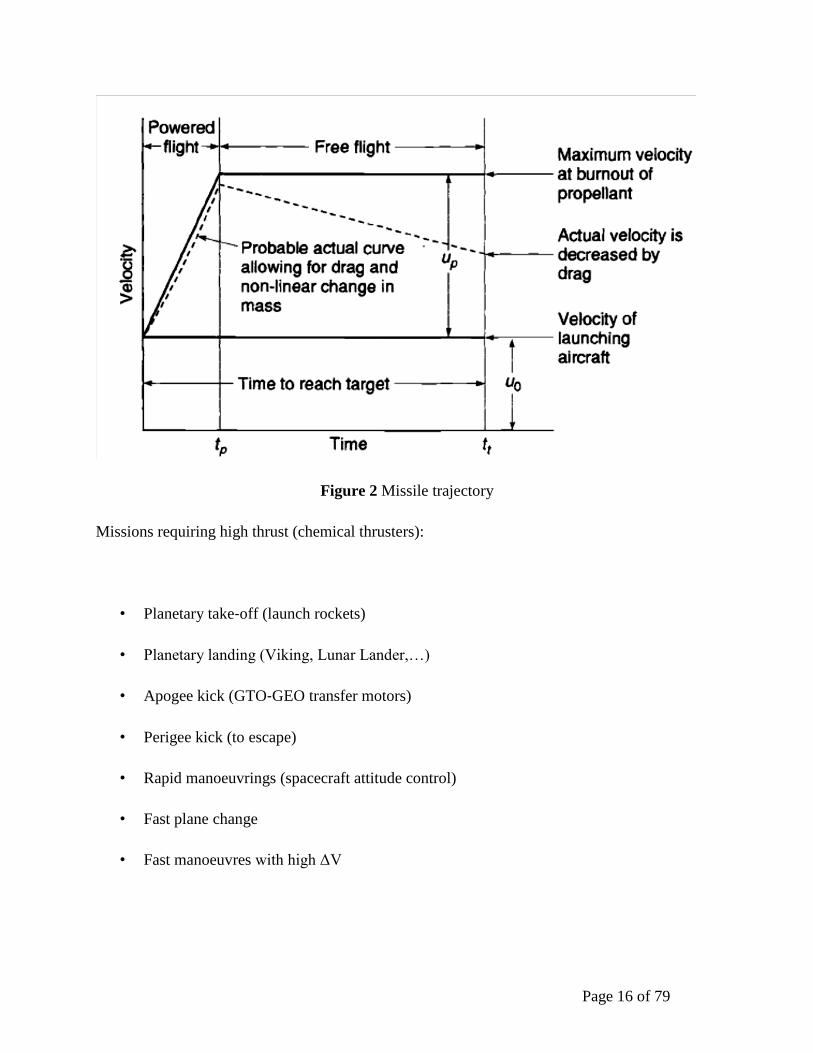
Simplified trajectory for an unguided, non-maneuvering, air-launched rocket projectile. The solid
line shows flight velocity without drag or gravity and dashed curve shows likely actual flight.
Page 16 of 79
Figure 2 Missile trajectory
Missions requiring high thrust (chemical thrusters):
• Planetary take‐off (launch rockets)
• Planetary landing (Viking, Lunar Lander,…)
• Apogee kick (GTO‐GEO transfer motors)
• Perigee kick (to escape)
• Rapid manoeuvrings (spacecraft attitude control)
• Fast plane change
• Fast manoeuvres with high ΔV
Page 17 of 79
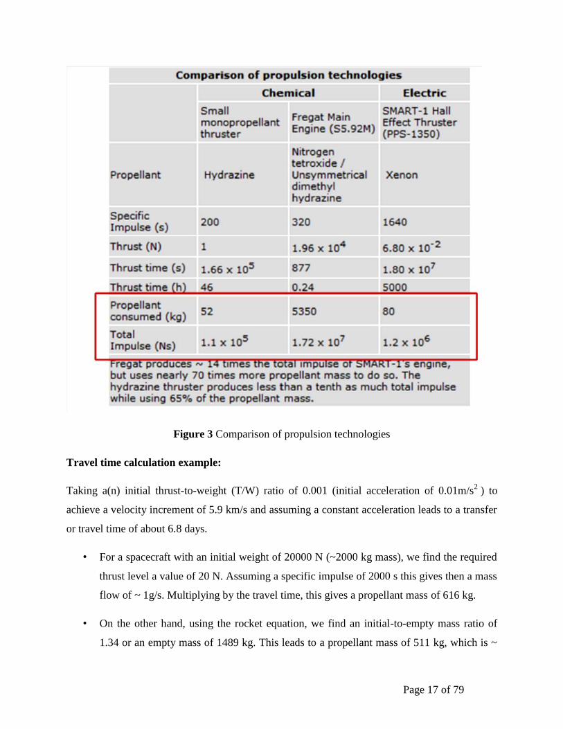
Figure 3 Comparison of propulsion technologies
Travel time calculation example:
Taking a(n) initial thrust-to-weight (T/W) ratio of 0.001 (initial acceleration of 0.01m/s2 ) to
achieve a velocity increment of 5.9 km/s and assuming a constant acceleration leads to a transfer
or travel time of about 6.8 days.
• For a spacecraft with an initial weight of 20000 N (~2000 kg mass), we find the required
thrust level a value of 20 N. Assuming a specific impulse of 2000 s this gives then a mass
flow of ~ 1g/s. Multiplying by the travel time, this gives a propellant mass of 616 kg.
• On the other hand, using the rocket equation, we find an initial-to-empty mass ratio of
1.34 or an empty mass of 1489 kg. This leads to a propellant mass of 511 kg, which is ~

Page 18 of 79
100 kg below the propellant mass estimated assuming a constant acceleration. Since mass
flow of propellant is constant, we find for the travel time 511 kg / 1 g/s = 511000 s = 5.91
days.
Page 19 of 79
Unit II
AIR-BREATHING ENGINES FOR HYPERSONIC TRANSPORT PLANES AND
MILITARYMISSILES- SUPERSONIC COMBUSTION- THE SCRAM-JET ENGINE
INTRODUCTION
Emerging hypersonic air-breathing propulsion systems offer the potential to enable new classes
of flight vehicles that allow rapid response at long range, more maneuverable flight, better
survivability, and routine and assured access to space. H historically, rocket boosters have been
used to propel hypersonic vehicles (i.e., those flying faster than 5 times the local speed of sound)
for applications such as space launch, long-range ballistic flight, and air-defense interceptor
missiles. Air-breathing propulsion systems currently under development will provide a means for
sustained and accelerating flight within the atmosphere at hypersonic speeds. Potential mission
areas include long-range cruise missiles for attack of time-sensitive targets, flexible high-altitude
Atmospheric interceptors, responsive hypersonic aircraft for global payload delivery, and
reusable launch vehicles for efficient space access. Although hypersonic air-breathing propulsion
systems have been investigated for the past 40 years without the development of an operational
system, significant technology advancements have been realized recently, and the development
of operational hypersonic systems appears to be within our grasp. In particular, the technology to
support a baseline hypersonic propulsion system exists that will allow operation at speeds up to
Mach 6 with conventional liquid hydrocarbon fuels.
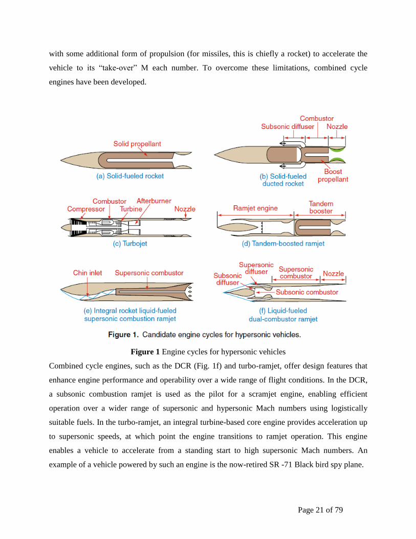
Hypersonic propulsion systems can be categorized as liquid- and solid-fuelled rockets, turbojets,
ramjets, ducted rockets, scramjets, and the dual-combustion ramjet (DCR). All existing
hypersonic systems use either liquid or solid rockets as their propulsion system. As with liquid-
fueled rockets, solid-fueled rockets (Fig. 1a) carry both fuel and oxidizer—either separately in
liquid fuel tanks
Or combined with a solid propellant grain—which are burned within a high-pressure chamber to
produce hot gaseous products that are expanded through an exhaust nozzle to produce thrust.
Both types of rocket system have drawbacks. Liquid engines typically operate with either
Page 20 of 79
cryogenic or toxic storable propellants, while solid propellant systems usually cannot be throttled
or stopped
And restarted. Some of the drawbacks of pure rocket motors, mainly the inefficiency of carrying
all required oxidizers on board, can be addressed by using a ducted rocket. Figure 1b shows a
ducted rocket where the fuel rich effluent of a rocket motor is mixed in a downstream combustor
with air captured from the atmosphere to improve the efficiency of the engine cycle.
Further improvement in efficiency is achieved by using pure air-breathing engines, which
capture all of their needed oxygen from within the atmosphere instead of carrying oxidizers. This
results in more efficient engine operation (albeit at generally lower thrust levels) and the ability
to use conventional hydrocarbon fuels. A key feature of these engines is that in addition to being
highly efficient they can be throttled to allow trajectory flexibility.
Pure air-breathing engines can be subdivided into turbojets, ramjets, scramjets, DCR s, and
turbo-ramjets. Conventional turbojets (Fig. 1c) use mechanical compression in the inlet, driven
by a turbine located downstream of the combustion process, to provide a portion of the airstream
compression. The maximum speed of a turbojet is usually limited to a Mach number of about 3.5
by the allowable turbine blade temperature, although options for higher-speed applications are
under investigation. As flight speed is increased, the mechanical compression within a turbojet is
not required, so the ramjet cycle (Fig. 1d)—which relies on the compression inherent in
capturing and slowing a supersonic airstream to the subsonic conditions where combustion
occurs—becomes feasible. At still higher speeds, the losses associated with decelerating the
captured airstream to subsonic speeds become large and the supersonic combustion ramjet, or
scramjet, the cycle is preferred. In the scramjet engine (Fig. 1e), the captured airstream is still
compressed by the inlet, but the combustion is allowed to occur at supersonic speeds.
Ramjets and scramjets can operate efficiently at supersonic and hypersonic speeds, but there tend
to be limitations to the range of Mach numbers over which they can operate. For instance, the
need to have sufficient compression in the inlet ordinarily requires that the ramjet engine operate
supersonically. The inefficiencies of slowing the flow down to subsonic speeds makes the ramjet
difficult to use for speeds exceeding Mach 5. Scramjets can be used above approximately Mach
5 but below that there is in general insufficient energy in the captured airstream to enable
efficient combustion in the supersonic combustor. Both the ramjet and scramjet must be coupled
Page 21 of 79
with some additional form of propulsion (for missiles, this is chiefly a rocket) to accelerate the
vehicle to its “take-over” M each number. To overcome these limitations, combined cycle
engines have been developed.
Figure 1 Engine cycles for hypersonic vehicles
Combined cycle engines, such as the DCR (Fig. 1f) and turbo-ramjet, offer design features that
enhance engine performance and operability over a wide range of flight conditions. In the DCR,
a subsonic combustion ramjet is used as the pilot for a scramjet engine, enabling efficient
operation over a wider range of supersonic and hypersonic Mach numbers using logistically
suitable fuels. In the turbo-ramjet, an integral turbine-based core engine provides acceleration up
to supersonic speeds, at which point the engine transitions to ramjet operation. This engine
enables a vehicle to accelerate from a standing start to high supersonic Mach numbers. An
example of a vehicle powered by such an engine is the now-retired SR -71 Black bird spy plane.

Page 22 of 79
To give a general understanding of the relative efficiency of the various engine cycles described
above, Fig. 2 shows the specific impulse, i.e., the pounds of thrust generated per pound of fuel
flow used, for the various engine cycles as a function of Mach number.
Information is presented for a range of engine cycles, with the air-breathing engines using either
hydrogen or liquid hydrocarbon as fuel.
TECHNOLOGY CHALLENGES
Let’s now turn our attention to engine technology needed to achieve hypersonic flight (generally
considered to be a flight at M each number>5). We focus on the use of air-breathing engines
because that engine technology will enable a whole new class of flight vehicles capable of
achieving hypersonic cruise within the atmosphere.
As mentioned above, the primary air-breathing engine cycle used for flight at speeds
approaching
Hypersonic flight (Mach numbers above ≈5) is the ramjet. At supersonic speeds, a ramjet-
powered vehicle utilizes an inlet that is designed to capture atmospheric air and compress that air
to prepare it for combustion.
Once the air is compressed, it is ducted into a combustor where it is mixed with fuel, and the
mixture is burned to raise the temperature and pressure inside the engine. The ducting that
delivers the air from the inlet to the combustor is called the diffuser (the term commonly used for
subsonic combustion ramjets) or isolator (the term commonly used for scramjets). For subsonic
combustion ramjet engines, the diffuser compresses the captured airstream, slowing the flow
from the supersonic flight speeds down to approximately 300 ft/s for delivery to the combustor.
Once the fuel/air mixture is burned in the combustor, the mixture is passed through a
converging/diverging nozzle and accelerated, exiting the engine once again at supersonic speeds.
Above Mach 5 there is a high price to pay for slowing the flow down to subsonic speeds, so for
these hypersonic speeds, supersonic combustion ramjets (scramjets) are preferred. For scramjet
engines, the flow captured by the inlet is still slowed to increase the pressure and temperature
prior to combustion, but the flow entering the combustor remains supersonic. The design for both
Page 23 of 79
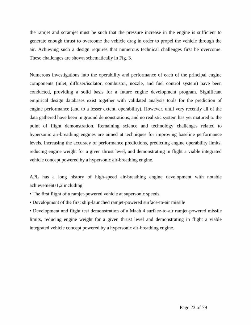
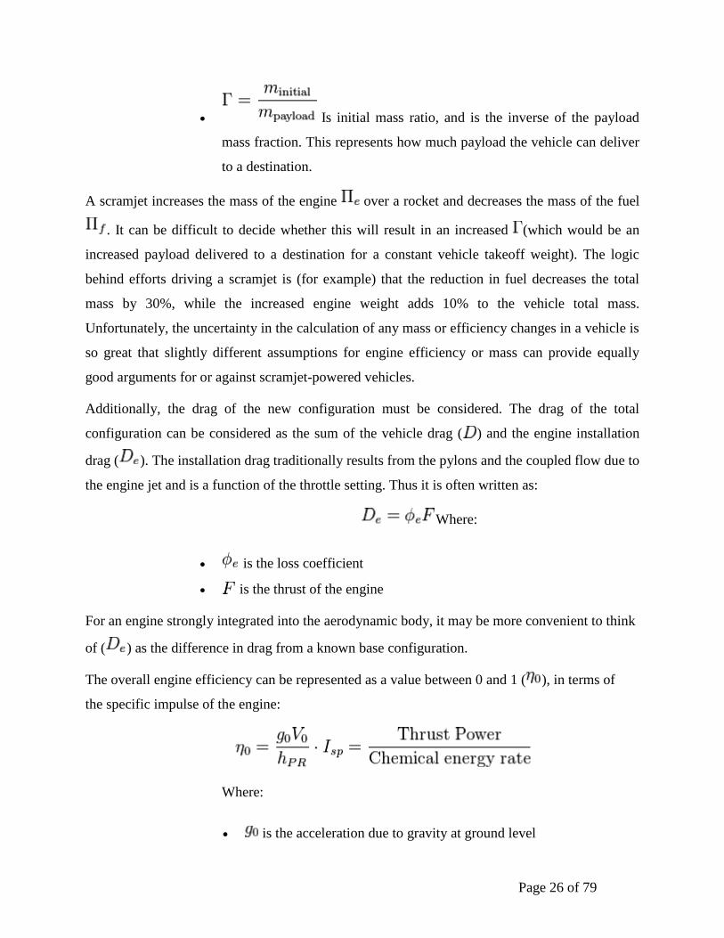
the ramjet and scramjet must be such that the pressure increase in the engine is sufficient to
generate enough thrust to overcome the vehicle drag in order to propel the vehicle through the
air. Achieving such a design requires that numerous technical challenges first be overcome.
These challenges are shown schematically in Fig. 3.
Numerous investigations into the operability and performance of each of the principal engine
components (inlet, diffuser/isolator, combustor, nozzle, and fuel control system) have been
conducted, providing a solid basis for a future engine development program. Significant
empirical design databases exist together with validated analysis tools for the prediction of
engine performance (and to a lesser extent, operability). However, until very recently all of the
data gathered have been in ground demonstrations, and no realistic system has yet matured to the
point of flight demonstration. Remaining science and technology challenges related to
hypersonic air-breathing engines are aimed at techniques for improving baseline performance
levels, increasing the accuracy of performance predictions, predicting engine operability limits,
reducing engine weight for a given thrust level, and demonstrating in flight a viable integrated
vehicle concept powered by a hypersonic air-breathing engine.
APL has a long history of high-speed air-breathing engine development with notable
achievements1,2 including
• The first flight of a ramjet-powered vehicle at supersonic speeds
• Development of the first ship-launched ramjet-powered surface-to-air missile
• Development and flight test demonstration of a Mach 4 surface-to-air ramjet-powered missile
limits, reducing engine weight for a given thrust level and demonstrating in flight a viable
integrated vehicle concept powered by a hypersonic air-breathing engine.
Page 24 of 79
Figure 2 Hypersonic engine
• The first demonstration of stable supersonic combustion for propulsion applications
• The first long-duration hydrogen-fuelled scramjet combustor tests at speeds greater than Mach
10
• The first successful ground tests at hypersonic speeds of a full-scale, liquid-hydrocarbon–
fuelled scramjet engine integrated into a missile-like configuration From this basis of significant
propulsion advancements the following technical challenges are identified to provide the science
and technology vision for hypersonic air-breathing propulsion technology development.
Hypersonic air-breathing engines are being investigated and developed for application to new
mission areas such as time-critical strike, access to space, and hypersonic global reach. APL has
had a leadership position in this technology from its inception and continues to be on the
forefront of developing the science and technology associated with these engines. Through
combined experimental, analytical, and computational investigations, significant improvement in
the performance and operability of hypersonic engines can be realized. This technology, when
closely coupled with emerging systems, offers the potential to provide truly transformational
capabilities.

Page 25 of 79
Vehicle performance
Figure 3 The specific impulse of various engines
The performance of a launch system is complex and depends greatly on its weight. Normally
craft is designed to maximize range ( ), orbital radius ( ) or payload mass fraction ( ) for a
given engine and fuel. This results in tradeoffs between the efficiency of the engine (takeoff fuel
weight) and the complexity of the engine (takeoff dry weight), which can be expressed by the
following:
Where:
Is the empty mass fraction and represents the weight of
the superstructure, tankage, and engine.
Is the fuel mass fraction and represents the weight of
fuel, oxidizer and any other materials which are consumed during the
launch.
Page 26 of 79
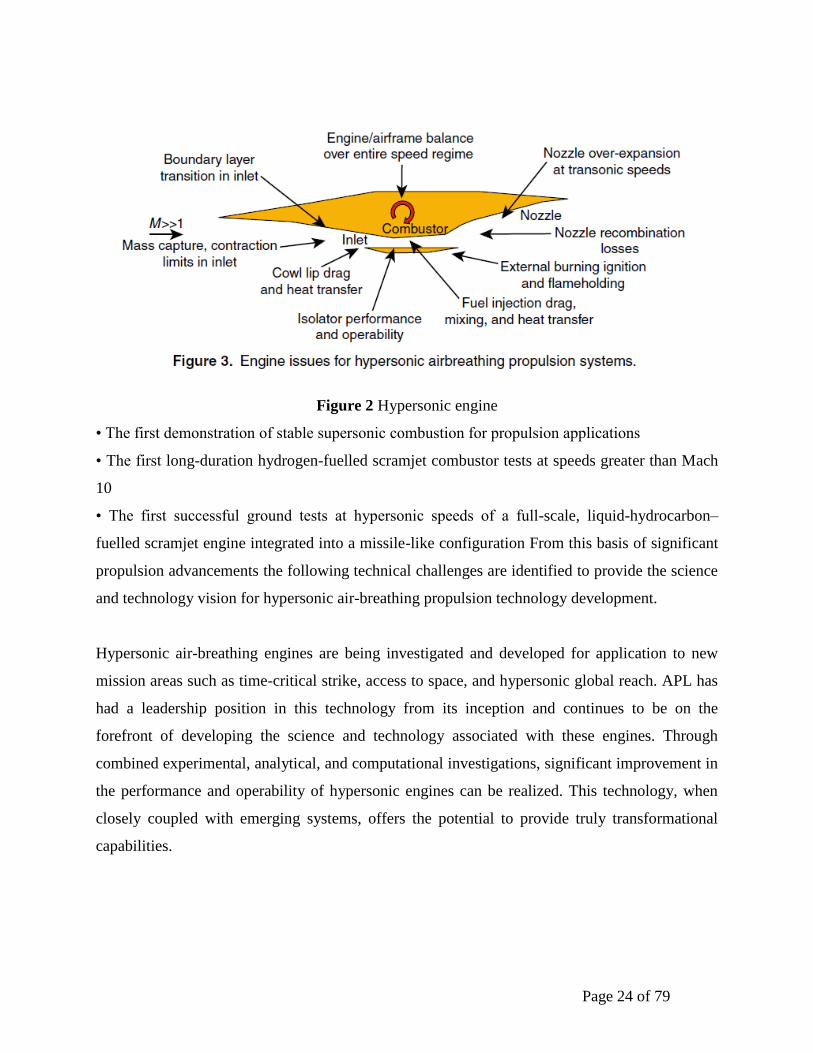
Is initial mass ratio, and is the inverse of the payload
mass fraction. This represents how much payload the vehicle can deliver
to a destination.
A scramjet increases the mass of the engine over a rocket and decreases the mass of the fuel
. It can be difficult to decide whether this will result in an increased (which would be an
increased payload delivered to a destination for a constant vehicle takeoff weight). The logic
behind efforts driving a scramjet is (for example) that the reduction in fuel decreases the total
mass by 30%, while the increased engine weight adds 10% to the vehicle total mass.
Unfortunately, the uncertainty in the calculation of any mass or efficiency changes in a vehicle is
so great that slightly different assumptions for engine efficiency or mass can provide equally
good arguments for or against scramjet-powered vehicles.
Additionally, the drag of the new configuration must be considered. The drag of the total
configuration can be considered as the sum of the vehicle drag ( ) and the engine installation
drag ( ). The installation drag traditionally results from the pylons and the coupled flow due to
the engine jet and is a function of the throttle setting. Thus it is often written as:
Where:
is the loss coefficient
is the thrust of the engine
For an engine strongly integrated into the aerodynamic body, it may be more convenient to think
of ( ) as the difference in drag from a known base configuration.
The overall engine efficiency can be represented as a value between 0 and 1 ( ), in terms of
the specific impulse of the engine:
Where:
is the acceleration due to gravity at ground level
Page 27 of 79
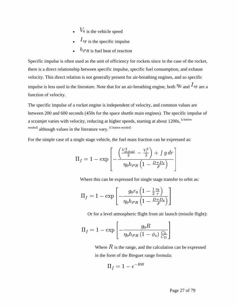
is the vehicle speed
is the specific impulse
is fuel heat of reaction
Specific impulse is often used as the unit of efficiency for rockets since in the case of the rocket,
there is a direct relationship between specific impulse, specific fuel consumption, and exhaust
velocity. This direct relation is not generally present for air-breathing engines, and so specific
impulse is less used in the literature. Note that for an air-breathing engine, both and are a
function of velocity.
The specific impulse of a rocket engine is independent of velocity, and common values are
between 200 and 600 seconds (450s for the space shuttle main engines). The specific impulse of
a scramjet varies with velocity, reducing at higher speeds, starting at about 1200s, [citation
needed] although values in the literature vary.
[Citation needed]
For the simple case of a single stage vehicle, the fuel mass fraction can be expressed as:
Where this can be expressed for single stage transfer to orbit as:
Or for a level atmospheric flight from air launch (missile flight):
Where is the range, and the calculation can be expressed
in the form of the Breguet range formula:
Page 28 of 79
Where:
is the lift coefficient
is the drag coefficient
This extremely simple formulation, used for the purposes of the discussion
assumes:
Single stage vehicle
No aerodynamic lift for the trans-atmospheric lifter However they are true generally
for all engines.
Chapter 3
CHEMICAL ROCKET ENGINES
Introduction
The mighty space rockets of today are the result of more than 2,000 years of invention,
experimentation, and discovery. First by observation and inspiration and then by methodical
research, the foundations for modern rocketry were laid. Building upon the experience of
two millennia, new rockets will expand human presence in space back to the Moon, to Mars
and the asteroids, and beyond. These new rockets will be versatile. They will support Earth
orbital missions, such as the International Space Station, and off-world missions millions of
kilometres from home.
Already, travel to the stars is possible. Robot spacecraft are on their way into interstellar
space as you read this. Someday, they will be followed by human explorers.
Chemical Propulsion Classifications
• Liquid Propellant • Pump Fed

Page 29 of 79
• Launch vehicles, large upper stages • Pressure Fed
• Smaller upper stages, spacecraft • Monopropellant
• Fuel only • Bipropellant
• Fuel & oxidizer • Solid Propellant
• Launch vehicles, Space Shuttle, spacecraft • Fuel/ox in solid binder
• Hybrid • Solid fuel/liquid ox • Sounding rockets
Figure 1 Chemical Rocket
Page 30 of 79
The main system used for space propulsion is the rocket – a device that stores its own propellant
mass and expels this mass at high velocity to provide the force. This thrust is produced by the
rocket engine, by accelerating the propellant mass particles to the desired velocity and direction,
and the nozzle is that part of the rocket engine extending beyond the combustion chamber, see
Figure 1. Typically, the combustion chamber is a constant diameter duct into which propellants
are injected, mixed and burned. Its length is sufficient to allow complete combustion of the
propellants before the nozzle accelerates the gas products.
The nozzle is said to begin at the point where the chamber diameter begins to decrease. The flow
area is first reduced giving a subsonic (Mach number < 1) acceleration of the gas. The area
decreases until the minimum or throat area is reached. Here the gas velocity corresponds to a
Mach number of one. Then the nozzle accelerates the flow supersonically (Mach number > 1) by
providing a path of increasing flow area.
Simply stated, the nozzle uses the pressure generated in the combustion chamber, pc, to increase
thrust by accelerating the combustion gas to a high supersonic velocity. The nozzle exit velocity,
ve, that can be achieved is governed by the nozzle area ratio (i.e., the nozzle exit area, Ae,
divided by the throat area, at) commonly called the expansion ratio, ε.
Page 31 of 79
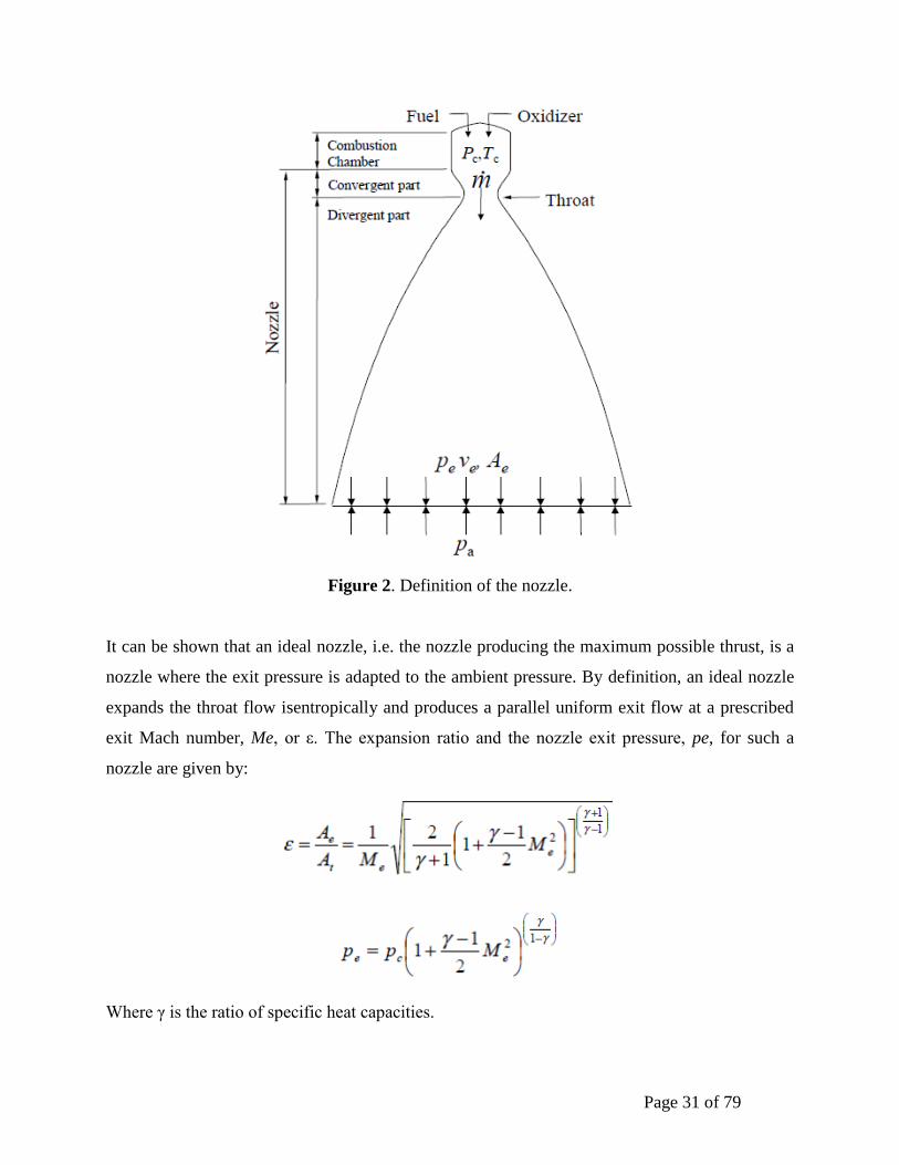
Figure 2. Definition of the nozzle.
It can be shown that an ideal nozzle, i.e. the nozzle producing the maximum possible thrust, is a
nozzle where the exit pressure is adapted to the ambient pressure. By definition, an ideal nozzle
expands the throat flow isentropically and produces a parallel uniform exit flow at a prescribed
exit Mach number, Me, or ε. The expansion ratio and the nozzle exit pressure, pe, for such a
nozzle are given by:
Where γ is the ratio of specific heat capacities.
Page 32 of 79
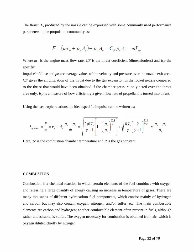
The thrust, F, produced by the nozzle can be expressed with some commonly used performance
parameters in the propulsion community as:
Where m_ is the engine mass flow rate, CF is the thrust coefficient (dimensionless) and Isp the
specific
impulse'm/s]. ve and pe are average values of the velocity and pressure over the nozzle exit area.
CF gives the amplification of the thrust due to the gas expansion in the rocket nozzle compared
to the thrust that would have been obtained if the chamber pressure only acted over the throat
area only. Isp is a measure of how efficiently a given flow rate of propellant is turned into thrust.
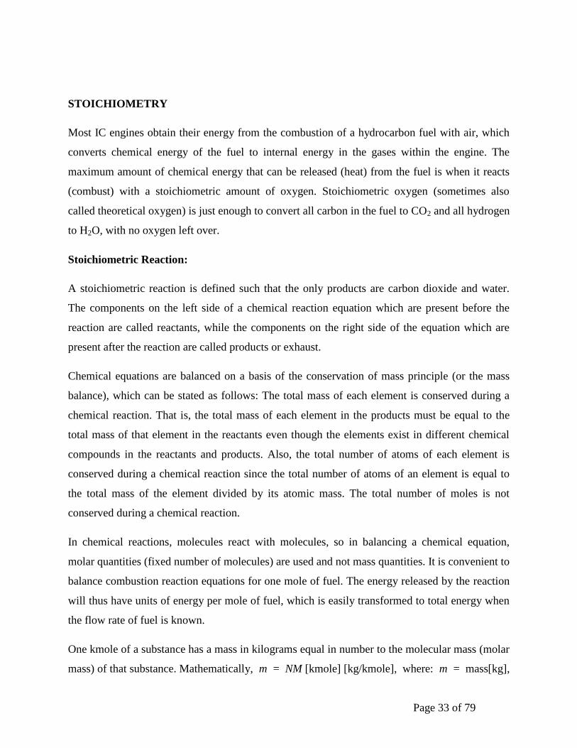
Using the isentropic relations the ideal specific impulse can be written as:
Here, Tc is the combustion chamber temperature and R is the gas constant.
COMBUSTION
Combustion is a chemical reaction in which certain elements of the fuel combines with oxygen
and releasing a large quantity of energy causing an increase in temperature of gases. There are
many thousands of different hydrocarbon fuel components, which consist mainly of hydrogen
and carbon but may also contain oxygen, nitrogen, and/or sulfur, etc. The main combustible
elements are carbon and hydrogen; another combustible element often present in fuels, although
rather undesirable, is sulfur. The oxygen necessary for combustion is obtained from air, which is
oxygen diluted chiefly by nitrogen.
Page 33 of 79
STOICHIOMETRY
Most IC engines obtain their energy from the combustion of a hydrocarbon fuel with air, which
converts chemical energy of the fuel to internal energy in the gases within the engine. The
maximum amount of chemical energy that can be released (heat) from the fuel is when it reacts
(combust) with a stoichiometric amount of oxygen. Stoichiometric oxygen (sometimes also
called theoretical oxygen) is just enough to convert all carbon in the fuel to CO2 and all hydrogen
to H2O, with no oxygen left over.
Stoichiometric Reaction:
A stoichiometric reaction is defined such that the only products are carbon dioxide and water.
The components on the left side of a chemical reaction equation which are present before the
reaction are called reactants, while the components on the right side of the equation which are
present after the reaction are called products or exhaust.
Chemical equations are balanced on a basis of the conservation of mass principle (or the mass
balance), which can be stated as follows: The total mass of each element is conserved during a
chemical reaction. That is, the total mass of each element in the products must be equal to the
total mass of that element in the reactants even though the elements exist in different chemical
compounds in the reactants and products. Also, the total number of atoms of each element is
conserved during a chemical reaction since the total number of atoms of an element is equal to
the total mass of the element divided by its atomic mass. The total number of moles is not
conserved during a chemical reaction.
In chemical reactions, molecules react with molecules, so in balancing a chemical equation,
molar quantities (fixed number of molecules) are used and not mass quantities. It is convenient to
balance combustion reaction equations for one mole of fuel. The energy released by the reaction
will thus have units of energy per mole of fuel, which is easily transformed to total energy when
the flow rate of fuel is known.
One kmole of a substance has a mass in kilograms equal in number to the molecular mass (molar
mass) of that substance. Mathematically, m = NM [kmole] [kg/kmole], where: m = mass[kg],

Page 34 of 79
N = number of moles[kmole], M = molecular mass[kg/kmole], 1 kmole = 6.02 1026
molecules.
For example, the stoichiometric reaction of propane would be C3H8 + an O2 = b CO2 + d H2O
Carbon balance gives: b = 3; Hydrogen balance gives: 2d = 8 d = 4; Oxygen balance gives:
2a = 2b + d a = 5. Then, reaction equation becomes C3H8 + 5 O2 = 3 CO2 + 4 H2O
Very small powerful engines could be built if fuel were burned with pure oxygen. However, the
cost of using pure oxygen would be prohibitive and thus is not done. Air is used as the source of
oxygen to react with fuel. Nitrogen and argon are essentially chemically neutral and do not react
in the combustion process. Their presence, however, does affect the temperature and pressure in
the combustion chamber. Nitrogen usually enters a combustion chamber in large quantities at
low temperatures and exists at considerably higher temperatures, absorbing a large proportion of
the chemical energy released during combustion. When the products are at low temperature the
nitrogen is not significantly affected by the reaction. At very high temperatures a small fraction
of nitrogen reacts with oxygen, forming hazardous gases called NOx.
LEAN OR RICH MIXTURE REACTIONS
Fuel-air mixtures with more than or less than the stoichiometric air requirement can be burned.
Combustion can occur, within limits, i.e., the proportions of the fuel and air must be in the proper
range for combustion to begin. For example, natural gas will not burn in air in concentrations
less than 5 percent or greater than about 15 percent. With excess air or fuel-lean combustion, the
extra air appears in the products in unchanged form. With less than stoichiometric air
requirement, i.e., with fuel-rich combustion, there is insufficient oxygen to oxidize fully the fuel
C and H to CO2 and H2O. The products are a mixture of CO2 and H2O with carbon monoxide CO
and hydrogen H2 (as well as N2). Carbon monoxide is a colorless, odorless, poisonous gas which
can be further burned to form CO2. It is produced in any combustion process when there is a
deficiency of oxygen. It is very likely that some of the fuel will not get burned when there is a
deficiency of oxygen. This unburned fuel ends up as pollution in the exhaust of the engine.
Because the composition of the combustion products is significantly different for fuel-lean and
fuel-rich mixtures, and because the stoichiometric fuel/air ratio depends on fuel composition, the
ratio of the actual fuel/air ratio to the stoichiometric ratio (or its inverse) is a more informative
Page 35 of 79
parameter for defining mixture composition. Various terminology is used for the amount of air or
oxygen used in combustion. 80% stoichiometric air = 80% theoretical air = 80% air = 20%
deficiency of air; 120% stoichiometric air = 120% theoretical air = 120% air = 20% excess air
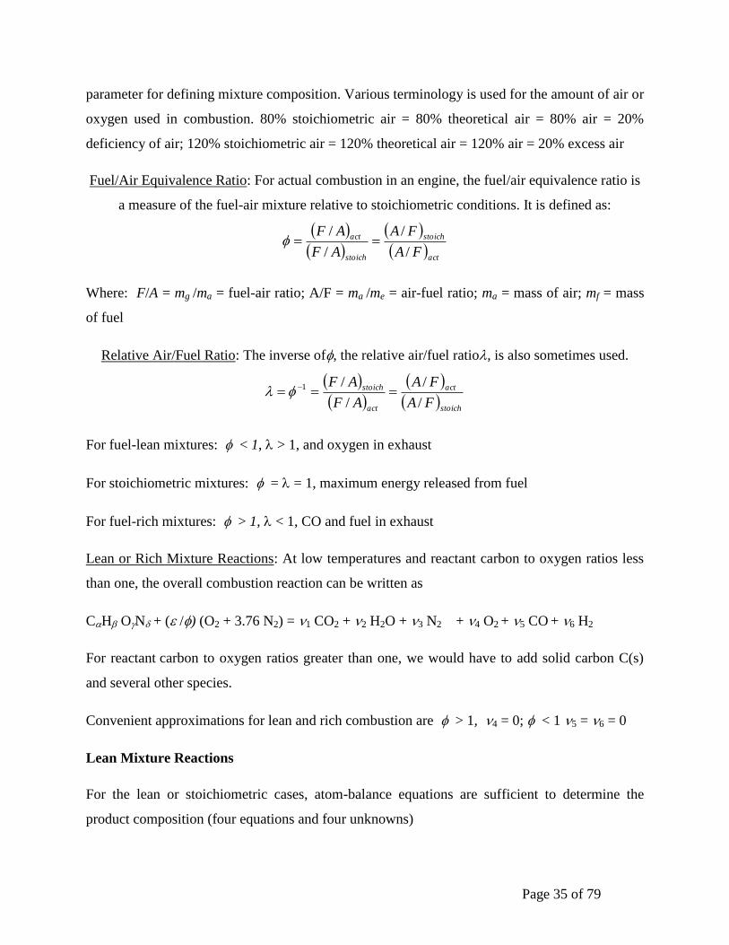
Fuel/Air Equivalence Ratio: For actual combustion in an engine, the fuel/air equivalence ratio is
a measure of the fuel-air mixture relative to stoichiometric conditions. It is defined as:
Where: F/A = mg /ma = fuel-air ratio; A/F = ma /me = air-fuel ratio; ma = mass of air; mf = mass
of fuel
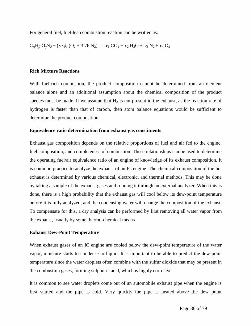
Relative Air/Fuel Ratio: The inverse of, the relative air/fuel ratio, is also sometimes used.
For fuel-lean mixtures: < 1, > 1, and oxygen in exhaust
For stoichiometric mixtures: = = 1, maximum energy released from fuel
For fuel-rich mixtures: > 1, < 1, CO and fuel in exhaust
Lean or Rich Mixture Reactions: At low temperatures and reactant carbon to oxygen ratios less
than one, the overall combustion reaction can be written as
CH ON + ( /) (O2 + 3.76 N2) = 1 CO2 + 2 H2O + 3 N2 + 4 O2 + 5 CO + 6 H2
For reactant carbon to oxygen ratios greater than one, we would have to add solid carbon C(s)
and several other species.
Convenient approximations for lean and rich combustion are > 1, 4 = 0; < 1 5 = 6 = 0
Lean Mixture Reactions
For the lean or stoichiometric cases, atom-balance equations are sufficient to determine the
product composition (four equations and four unknowns)
act
stoich
stoich
act
FA
FA
AF
AF
/
/
/
/
stoich
act
act
stoich
FA
FA
AF
AF
/
/
/
/1
Page 36 of 79
For general fuel, fuel-lean combustion reaction can be written as:
CH ON + ( /) (O2 + 3.76 N2) = 1 CO2 + 2 H2O + 3 N2 + 4 O2
Rich Mixture Reactions
With fuel-rich combustion, the product composition cannot be determined from an element
balance alone and an additional assumption about the chemical composition of the product
species must be made. If we assume that H2 is not present in the exhaust, as the reaction rate of
hydrogen is faster than that of carbon, then atom balance equations would be sufficient to
determine the product composition.
Equivalence ratio determination from exhaust gas constituents
Exhaust gas composition depends on the relative proportions of fuel and air fed to the engine,
fuel composition, and completeness of combustion. These relationships can be used to determine
the operating fuel/air equivalence ratio of an engine of knowledge of its exhaust composition. It
is common practice to analyze the exhaust of an IC engine. The chemical composition of the hot
exhaust is determined by various chemical, electronic, and thermal methods. This may be done
by taking a sample of the exhaust gases and running it through an external analyzer. When this is
done, there is a high probability that the exhaust gas will cool below its dew-point temperature
before it is fully analyzed, and the condensing water will change the composition of the exhaust.
To compensate for this, a dry analysis can be performed by first removing all water vapor from
the exhaust, usually by some thermo-chemical means.
Exhaust Dew-Point Temperature
When exhaust gases of an IC engine are cooled below the dew-point temperature of the water
vapor, moisture starts to condense to liquid. It is important to be able to predict the dew-point
temperature since the water droplets often combine with the sulfur dioxide that may be present in
the combustion gases, forming sulphuric acid, which is highly corrosive.
It is common to see water droplets come out of an automobile exhaust pipe when the engine is
first started and the pipe is cold. Very quickly the pipe is heated above the dew point

Page 37 of 79
temperature, and condensing water is then seen only as vapor when the hot exhaust is cooled by
the surrounding air, much more noticeable in the cold wintertime.
Combustion efficiency
Even when the flow of air and fuel into an engine is controlled exactly at stoichiometric
conditions, combustion will not be “perfect,” and components other than CO2, H2O, and N2 are
found in the exhaust products. One major reason for this is the extremely short time available for
each engine cycle, which often means that less than the complete mixing of the air and fuel is
obtained. Some fuel molecules do not find an oxygen molecule to react with, and small
quantities of both fuel and oxygen end up in the exhaust. In practice, the exhaust gas of an
internal combustion engine contains incomplete combustion products (e.g., CO, H2, unburned
hydrocarbons, soot) as well as complete combustion products (CO2 and H2O).
Under lean operating conditions the amounts of incomplete combustion products are small.
Under fuel-rich operating conditions these amounts become more substantial since there is
insufficient oxygen to complete combustion.
DISSOCIATION
In actual engine performance, the combustion usually is not complete even in the presence of
excess air, because of dissociation at high temperature and also the unsatisfactory mixing of the
air and the fuel. When hydrocarbon fuels react with oxygen (air) at high engine temperatures
(greater than about 2200 K), dissociation of normally stable components can occur. CO2,
dissociates to CO and O, O2 dissociates to monatomic O, N2 dissociates to N, etc. This not only
affects chemical combustion but is a cause of one of the major emission problems of IC engines.
Nitrogen as diatomic N2 does not react with other substances, but when it dissociates to
monatomic nitrogen at high temperature it readily reacts with oxygen to form Nitrogen dioxide
(NOx), a major pollutant from automobiles e.g., NO (Nitric oxide) and NO2 (Nitrogen dioxide).
(Note: N2O is Nitrous oxide). In such cases, the exhaust gases may contain certain percentages of
CO, H2, NO, OH, H, O, and CH4. To avoid generating large amounts of nitrogen oxides,
combustion temperatures in automobile engines are lowered, which reduces the dissociation of
N2. Unfortunately, this also lowers the thermal efficiency of the engine.

Page 38 of 79
CHEMICALLY REACTING GAS MIXTURES
The working fluids in engines are mixtures of gases. Depending on the problem under
consideration and the portion of the engine cycle in which it occurs chemical reactions may:
(1) Be so slow that they have a negligible effect on mixture composition (the mixture
composition is essentially “frozen”);
(2) Be so rapid that the mixture state changes and the composition remains in chemical
equilibrium;
(3) Be one of the rate-controlling processes that determine how the composition of the mixture
changes with time.
Chemical Equilibrium:
It is a good approximation for performance estimates in engines to regard the burned gases
produced by the combustion of fuel and air as in chemical equilibrium. It means that the
chemical reactions, by which individual species in the burned gases react together, produce and
remove each species at equal rates. No net change in species composition results. For example, if
the temperature of a mass of CO2 gas in a vessel is increased sufficiently, some of the CO2
molecules dissociate into CO and O2 molecules. If the mixture of CO2, CO, and O2 is in
equilibrium, then CO2 molecules are dissociating into CO and O2 at the same rate as CO and O2
molecules are recombining in the proportions required to satisfy the equation CO + ½O2
CO2
Owing to the dissociation when carbon and hydrogen react with the oxygen of the air, the
reaction does not proceed to the point where all carbon and hydrogen are consumed, forming
CO2 and H2O. Instead, the reactions proceed only until an equilibrium condition is reached in
which not only the final products of the reaction, CO2, and H2O, are present, but also certain
amounts of the original reaction substances and some intermediate compounds. The second law
of thermodynamics defines the criterion for chemical equilibrium, in which minimization of
Gibbs free energy is considered.
Practical Chemical Equilibrium:
Page 39 of 79
The proportions, at equilibrium, of the different constituents of the products of combustion,
depend on the original proportions and on the temperature and pressure reached at the end of the
reaction. The higher the final temperature, the less complete the combustion reaction. On the
other hand, the higher the pressure, the more complete the reaction. In fuel-air mixtures at
equilibrium after combustion, the following substances usually are present: CO2, H2O, N2, O2,
CO, H2, H, O, OH, NO, C, and CH4. However, free carbon, C, and methane, CH4, are present in
such small portions that they can be disregarded. If we consider, H, O, OH and NO the only
species of importance because of dissociation then the reaction equation be written as:
CH ON + ( /) (O2 + 3.76 N2) = 1 CO2 + 2 H2O + 3 N2 + 4 O2 + 5 CO + 6 H2 + 7 H
+ 8 O + 9 OH + 10 NO
Atom balancing yields the four equations. Introduction of six equilibrium constants will yield ten
equations for the ten unknowns. A solution can be obtained by solving these equations for the
given fuel composition, fuel/air equivalence ratio, and product pressure and temperature.
Chemical Reaction Rates:
Whether a system is in chemical equilibrium depends on whether the time constants of the
controlling chemical reactions are short compared with timescales over which the system
conditions (temperature and pressure) change. Chemical processes in engines are often not in
equilibrium. Important examples of non-equilibrium phenomena are the flame reaction zone
where the fuel is oxidized, and the air-pollutant formation mechanism. Such non-equilibrium
processes are controlled by the rate at which actual chemical reactions which convert reactants to
products occur. The rates at which chemical reactions proceed depend on the concentration of
the reactants, temperature, and whether any catalyst is present. This field is called chemical
kinetics.
Unburned Mixture Composition:
Page 40 of 79
During the exhaust stroke of an engine, not all of the exhaust gases pushed out of the cylinder by
the piston, a small residual being trapped in the clearance volume. The amount of this residual
depends on the compression ratio, and somewhat on the location of the valves and valve overlap.
The unburned mixture for a spark ignition engine during intake and compression consists of air,
fuel, and previously burned gases. It is, therefore, a mixture of CO2, H2O, N2, O2, CO, and H2 for
fuel-rich mixtures, and fuel (usually vapor). The composition of the unburned mixture does not
change significantly during intake and compression. It is sufficiently accurate to assume the
composition is frozen. For the compression ignition engine, the unburned mixture prior to
injection contains no fuel; it consists of air and previously burned gas. The combustion products
or burned mixture gases, during the combustion process and much of the expansion process, are
close to thermodynamic equilibrium. As these combustion products cool, recombination occurs.
Towards the end of the expansion process, the gas composition departs from the equilibrium
composition; recombination no longer occurs fast enough to maintain the reacting mixture in
equilibrium. During the exhaust process, reactions are sufficiently slow so that for calculating
thermodynamic properties the composition can be regarded as frozen. The mass of charge
trapped in the cylinder (mc) is the inducted mass per cycle (mi), plus the residual mass (Mr), left
over from the previous cycle. The residual fraction (XR) is XR = Mr / mc. Typical residual
fractions in SI engines range from 20% at light load to 7% at full load. In CI engines the residual
fraction is smaller ( a few percent) due to the higher compression ratio, and in naturally aspirated
engines is approximately constant since the intake is un throttled. If the inducted mixture is fuel
and air (or air only), then the burned gas fraction (xb) in the unburned mixture during
compression equals the residual fraction.
Exhaust Gas Recirculation:
In some engines, a fraction of the engine exhaust gases is recycled to the intake to dilute the
fresh mixture for control of NOx emissions. If the percent of exhaust gas recycled (%EGR) is
defined as the percent of the total intake mixture which is recycled exhaust, EGR (%) = mEGR /
mi, where mEGR is the mass of exhaust gas recycled, then the burned gas fraction in the fresh
mixture is . rr
c
rEGR
b xxEGR
m
mmx
1
100

Page 41 of 79
Up to about 30% of the exhaust can be recycled; the burned gas fraction during compression
can, therefore, approach 30 to 40%.
Heat Of Combustion: From steady-flow energy balance equation with no work interaction heat
liberated by the combustion reaction of a hydrocarbon fuel with air is the difference between the
total enthalpy of the products and the total enthalpy of the reactants. This is called heat of
reaction, enthalpy of reaction, the heat of combustion, or enthalpy of combustion and is given by:
,
Where: Ni = number of moles of component i, , = enthalpy of formation, the
enthalpy needed to form one mole of that component at standard conditions of 25C and 1 atm,
hi = change of enthalpy from standard temperature for component i.
Q will be negative, meaning that heat is given up by the reacting gases.
Values of and h are molar-specific quantities and can be found in tables. The enthalpy of
combustion of a particular fuel will be different at different temperatures and pressures.
REACTPROD
iiii hNhNQ
ifi hhh 0 0
fh
0
fh
Page 42 of 79
Unit 4
Liquid Propellant Rocket Engines, Solid Propellant Rocket Motors
Design Consideration of Liquid Rocket Combustion Chamber
The combustion chamber is that part of a thrust chamber where the combustion or burning
of the propellant takes place. The combustion temperature is much higher than the melting points of
most chamber wall materials. Therefore it is necessary either to cool these walls or to stop rocket
operation before the critical wall areas become too hot. If the heat transfer is too high and thus the
wall temperatures become locally too high, the thrust chamber will fail.
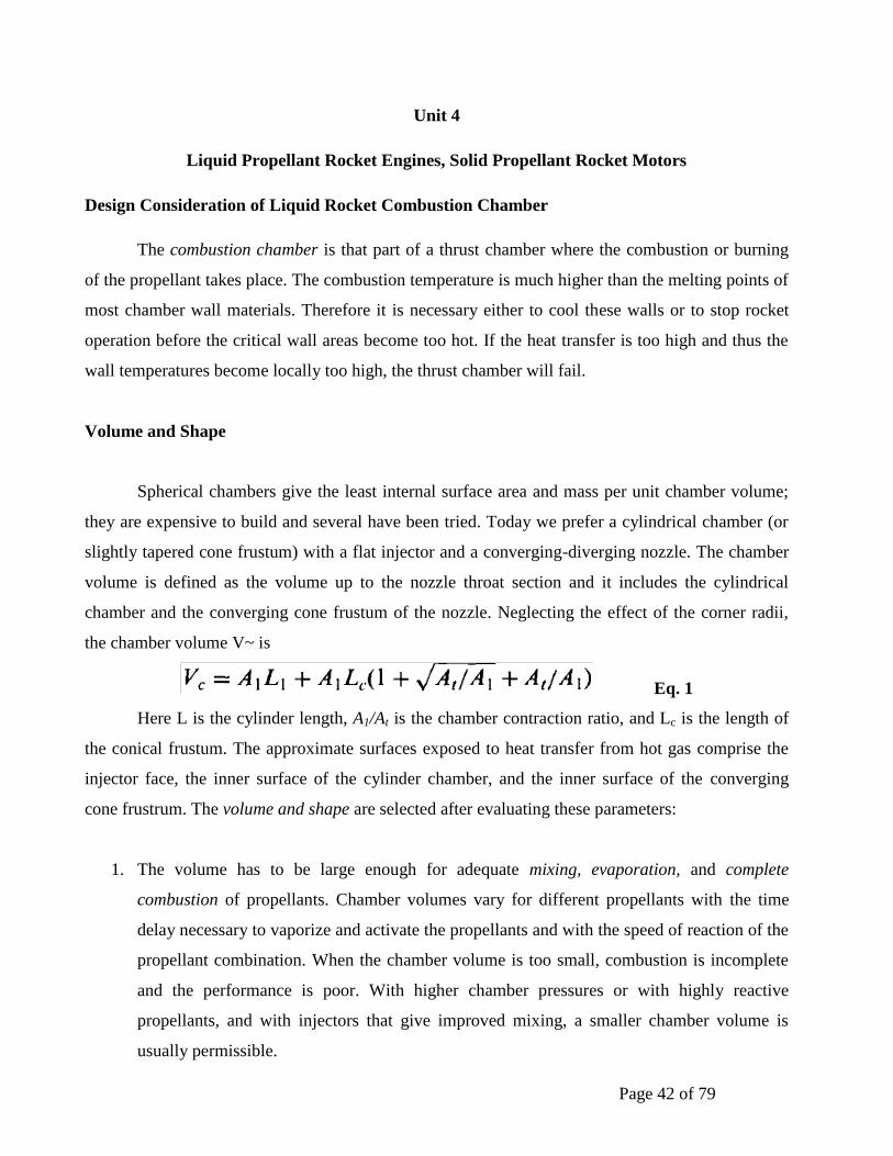
Volume and Shape
Spherical chambers give the least internal surface area and mass per unit chamber volume;
they are expensive to build and several have been tried. Today we prefer a cylindrical chamber (or
slightly tapered cone frustum) with a flat injector and a converging-diverging nozzle. The chamber
volume is defined as the volume up to the nozzle throat section and it includes the cylindrical
chamber and the converging cone frustum of the nozzle. Neglecting the effect of the corner radii,
the chamber volume V~ is
Eq. 1
Here L is the cylinder length, A1/At is the chamber contraction ratio, and Lc is the length of
the conical frustum. The approximate surfaces exposed to heat transfer from hot gas comprise the
injector face, the inner surface of the cylinder chamber, and the inner surface of the converging
cone frustrum. The volume and shape are selected after evaluating these parameters:
1. The volume has to be large enough for adequate mixing, evaporation, and complete
combustion of propellants. Chamber volumes vary for different propellants with the time
delay necessary to vaporize and activate the propellants and with the speed of reaction of the
propellant combination. When the chamber volume is too small, combustion is incomplete
and the performance is poor. With higher chamber pressures or with highly reactive
propellants, and with injectors that give improved mixing, a smaller chamber volume is
usually permissible.

Page 43 of 79
2. The chamber diameter and volume can influence the cooling requirements. If the chamber
volume and the chamber diameter are large, the heat transfer rates to the walls will be
reduced, the area exposed to heat will be large, and the walls are somewhat thicker.
Conversely, if the volume and cross section are small, the inner wall surface area and the
inert mass will be smaller, but the chamber gas velocities and the heat transfer rates will be
increased. There is an optimum chamber volume and diameter where the total heat absorbed
by the walls will be a minimum. This is important when the available cooling capacity of the
coolant is limited (for example oxygen-hydrocarbon at high mixture ratios) or if the
maximum permissive coolant temperature has to be limited (for safety reasons with
hydrazine cooling). The total heat transfer can also be further reduced by going to a rich
mixture ratio or by adding film cooling (discussed below).
3. All inert components should have minimum mass. The thrust chamber mass is a function of
the chamber dimensions, chamber pressure, and nozzle area ratio, and the method of
cooling.
4. Manufacturing considerations favour a simple chamber geometry, such as a cylinder with a
double cone bow-tie-shaped nozzle, low cost materials, and simple fabrication processes.
5. In some applications the length of the chamber and the nozzle relate directly to the overall
length of the vehicle. A large-diameter but short chamber can allow a somewhat shorter
vehicle with a lower structural inert vehicle mass.
6. The gas pressure drop for accelerating the combustion products within the chamber should
be a minimum; any pressure reduction at the nozzle inlet reduces the exhaust velocity and
the performance of the vehicle. These losses become appreciable when the chamber area is
less than three times the throat area.
7. For the same thrust the combustion volume and the nozzle throat area become smaller as the
operating chamber pressure is increased. This means that the chamber length and the nozzle
length (for the same area ratio) also decrease with increasing chamber pressure. The
performance also goes up with chamber pressure.
The preceding chamber considerations conflict with each other. It is, for instance, impossible to
have a large chamber that gives complete combustion but has a low mass. Depending on the
application, a compromise solution that will satisfy the majority of these considerations is therefore
usually selected and verified by experiment.

Page 44 of 79
The characteristic chamber length is defined as the length that a chamber of the same volume
would have if it were a straight tube and had no converging nozzle section.
Eq. 2
Where L* (pronounced el star) is the characteristic chamber length, At is the nozzle throat area,
and Vc is the chamber volume. The chamber includes all the volume up to the throat area. Typical
values for L* are between 0.8 and 3.0 meters (2.6 to 10 ft) for several bipropellants and higher for
some monopropellants. Because this parameter does not consider any variables except the throat
area, it is useful only for a particular propellant combination and a narrow range of mixture ratio
and chamber pressure. The parameter L* was used about 40 years ago, but today the chamber
volume and shape are chosen by using data from successful thrust chambers of prior similar designs
and identical propellants.
The stay time t~ of the propellant gases is the average value of the time spent by each molecule
or atom within the chamber volume. It is defined by
Eq. 3
Where m(dot) is the propellant mass flow, ~1 is the average specific volume or volume per unit
mass of propellant gases in the chamber, and Vc is the chamber volume. The minimum stay time at
which a good performance is attained defines the chamber volume that gives essentially complete
combustion. The stay time varies for different propellants and has to be experimentally determined.
It includes the time necessary for vaporization, activation, and complete burning of the propellant.
Stay times have values of 0.001 to 0.040 sec for different types of thrust chambers and propellants.
The nozzle dimensions and configuration can be determined from the analyses. The converging
section of the supersonic nozzle experiences a much higher internal gas pressure than the diverging
section and therefore the design of the converging wall is similar to the design of the cylindrical
chamber wall. Most thrust chambers use a shortened bell shape for the diverging nozzle section.
Nozzles with area ratios up to 400 have been developed.
It was stated that very large nozzle exit area ratios allow a small but significant
improvement in specific impulse, particularly at very high altitudes; however, the extra length and
extra vehicle mass necessary to house a large nozzle make this unattractive. This disadvantage can
be mitigated by a multipiece nozzle, that is stored in annular pieces around the engine during the
ascent of the launch vehicle and automatically assembled in space after launch vehicle separation

Page 45 of 79
and before firing. This concept, known as extendible nozzle cone, has been successfully employed
in solid propellant rocket motors for space applications for about 20 years. The first flight with an
extendible nozzle on a liquid propellant engine was performed in 1998 with a modified version of a
Pratt & Whitney upper stage engine.
Injector
The functions of the injector are similar to those of a carburetor of an internal combustion
engine. The injector has to introduce and meter the flow of liquid propellants to the combustion
chamber, cause the liquids to be broken up into small droplets (a process called atomization), and
distribute and mix the propellants in such a manner that a correctly proportioned mixture of fuel and
oxidizer will result, with uniform propellant mass flow and composition over the chamber cross
section. This has been accomplished with different types of injector designs and elements; several
common types are shown in Fig. 1 and complete injectors are shown in Fig. 2.
The injection hole pattern on the face of the injector is closely related to the internal
manifolds or feed passages within the injector. These provide for the distribution of the propellant
from the injector inlet to all the injection holes. A large complex manifold volume allows low
passage velocities and good distribution of flow over the cross section of the chamber. A small
manifold volume allows for a lighter weight injector and reduces the amount of "dribble" flow after
the main valves are shut. The higher passage velocities cause a more uneven flow through different
identical injection holes and thus a poorer distribution and wider local gas composition variation.
Dribbling results in afterburning, which is an inefficient irregular combustion that gives a little
"cutoff" thrust after valve closing. For applications with very accurate terminal vehicle velocity
requirements, the cut off impulse has to be very small and reproducible and often valves are built
into the injector to minimize passage volume.
Impinging-stream-type, multiple-hole injectors are commonly used with oxygen-
hydrocarbon and storable propellants. For unlike doublet patterns the propellants are injected
through a number of separate small holes in such a manner that the fuel and oxidizer streams
impinge upon each other. Impingement forms thin liquid fans and aids atomization of the liquids
into droplets, also aiding distribution. Impinging hole injectors are also used for like-on-like or self-
impinging patterns (fuel-on-fuel and oxidizer-on-oxidizer). The two liquid streams then form a fan
which breaks up into droplets. Unlike doublets work best when the hole size (more exactly, the

Page 46 of 79
volume flow) of the fuel is about equal to that of the oxidizer and the ignition delay is long enough
to allow the formation of fans. For uneven volume flow the triplet pattern seems to be more
effective.
The non-impinging or shower head injector employs non impinging streams of propellant
usually emerging normal to the face of the injector. It relies on turbulence and diffusion to achieve
mixing. The German World War II V-2 rocket used this type of injector. This type is now not used,
because it requires a large chamber volume for good combustion. Sheet or spray-type injectors give
cylindrical, conical, or other types of spray sheets; these sprays generally intersect and thereby
promote mixing and atomization. By varying the width of the sheet (through an axially moveable
sleeve) it is possible to throttle the propellant flow over a wide range without excessive reduction in
injector pressure drop. This type of variable area concentric tube injector was used on the descent
engine of the Lunar Excursion Module and throttled over a 10:1 range of flow with only a very
small change in mixture ratio.
The coaxial hollow post injector has been used for liquid oxygen and gaseous hydrogen
injectors by most domestic and foreign rocket designers. It is shown in the lower left of Fig. 1. It
works well when the liquid hydrogen has absorbed heat from cooling jackets and has been gasified.
This gasified hydrogen flows at high speed (typically 330 m/sec or 1000 ft/sec); the liquid oxygen
flows far more slowly (usually at less than 33 m/sec or 100 ft/sec) and the differential velocity
causes a shear action, which helps to break up the oxygen stream into small droplets. The injector
has a multiplicity of these coaxial posts on its face. This type of injector is not used with liquid
storable bipropellants, in part because the pressure drop to achieve high velocity would become too
high.
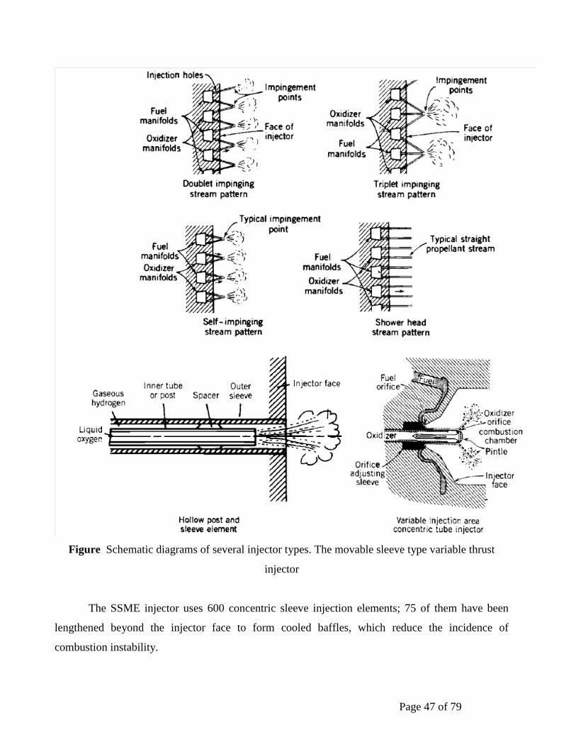
Page 47 of 79
Figure Schematic diagrams of several injector types. The movable sleeve type variable thrust
injector
The SSME injector uses 600 concentric sleeve injection elements; 75 of them have been
lengthened beyond the injector face to form cooled baffles, which reduce the incidence of
combustion instability.
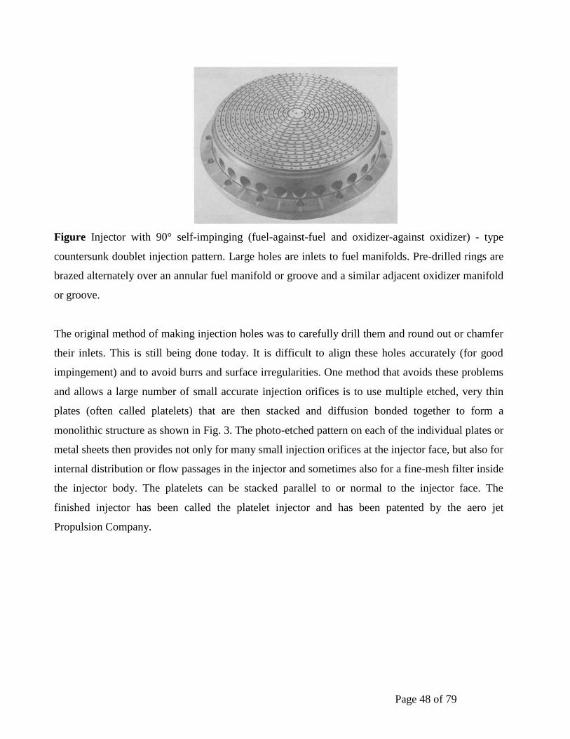
Page 48 of 79
Figure Injector with 90° self-impinging (fuel-against-fuel and oxidizer-against oxidizer) - type
countersunk doublet injection pattern. Large holes are inlets to fuel manifolds. Pre-drilled rings are
brazed alternately over an annular fuel manifold or groove and a similar adjacent oxidizer manifold
or groove.
The original method of making injection holes was to carefully drill them and round out or chamfer
their inlets. This is still being done today. It is difficult to align these holes accurately (for good
impingement) and to avoid burrs and surface irregularities. One method that avoids these problems
and allows a large number of small accurate injection orifices is to use multiple etched, very thin
plates (often called platelets) that are then stacked and diffusion bonded together to form a
monolithic structure as shown in Fig. 3. The photo-etched pattern on each of the individual plates or
metal sheets then provides not only for many small injection orifices at the injector face, but also for
internal distribution or flow passages in the injector and sometimes also for a fine-mesh filter inside
the injector body. The platelets can be stacked parallel to or normal to the injector face. The
finished injector has been called the platelet injector and has been patented by the aero jet
Propulsion Company.
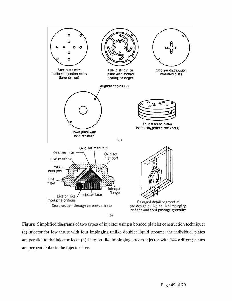
Page 49 of 79
Figure Simplified diagrams of two types of injector using a bonded platelet construction technique:
(a) injector for low thrust with four impinging unlike doublet liquid streams; the individual plates
are parallel to the injector face; (b) Like-on-like impinging stream injector with 144 orifices; plates
are perpendicular to the injector face.
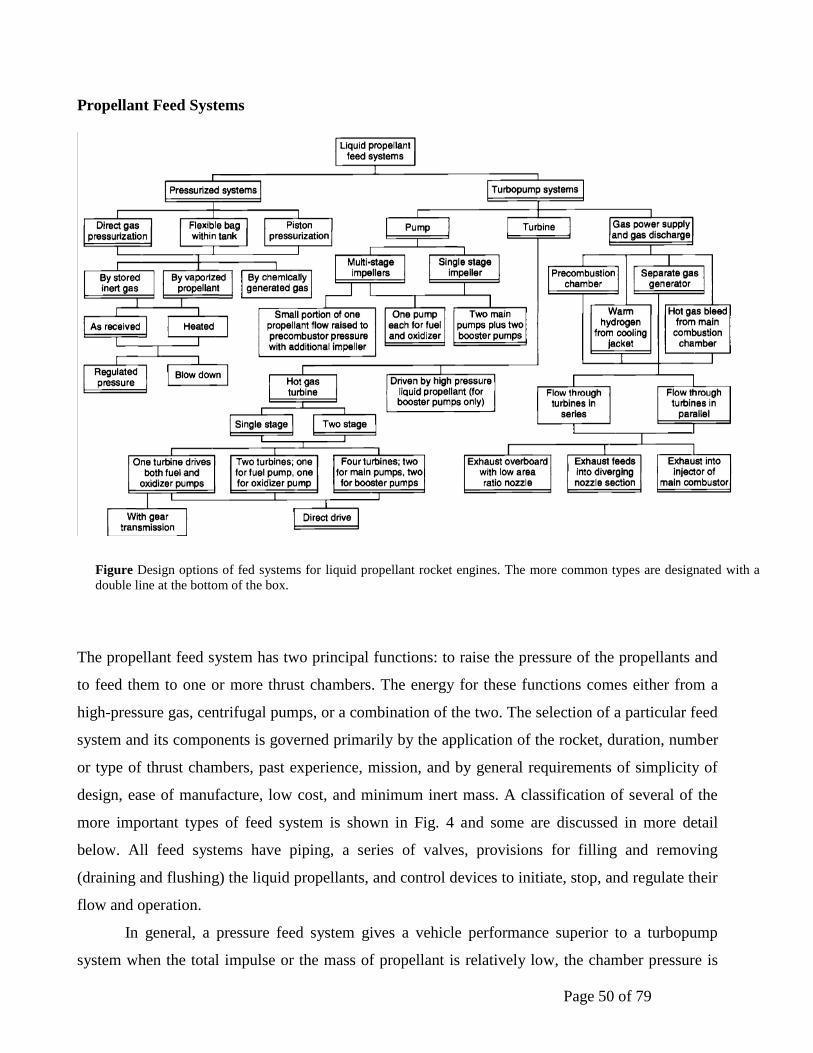
Page 50 of 79
Propellant Feed Systems
The propellant feed system has two principal functions: to raise the pressure of the propellants and
to feed them to one or more thrust chambers. The energy for these functions comes either from a
high-pressure gas, centrifugal pumps, or a combination of the two. The selection of a particular feed
system and its components is governed primarily by the application of the rocket, duration, number
or type of thrust chambers, past experience, mission, and by general requirements of simplicity of
design, ease of manufacture, low cost, and minimum inert mass. A classification of several of the
more important types of feed system is shown in Fig. 4 and some are discussed in more detail
below. All feed systems have piping, a series of valves, provisions for filling and removing
(draining and flushing) the liquid propellants, and control devices to initiate, stop, and regulate their
flow and operation.
In general, a pressure feed system gives a vehicle performance superior to a turbopump
system when the total impulse or the mass of propellant is relatively low, the chamber pressure is
Figure Design options of fed systems for liquid propellant rocket engines. The more common types are designated with a
double line at the bottom of the box.
Page 51 of 79
low, the engine thrust-to-weight ratio is low (usually less than 0.6), and when there are repeated
short-duration thrust pulses; the heavy-walled tanks for the propellant and the pressurizing gas
usually constitute the major inert mass of the engine system. In a turbo pump feed systems the
propellant tank pressures are much lower (by a factor of 10 to 40) and thus the tank masses are
much lower (again by a factor of 10 to 40).
Turbo pump systems usually give a superior vehicle performance when the total impulse is
large (higher Au) and the chamber pressure is higher. The pressurized feed system can be relatively
simple, such as for a single operation, factory-preloaded, simple unit (with burst diaphragms instead
of some of the valves), or quite complex, as with multiple restart able thrusters or reusable systems.
If the propulsion system is to be reusable or is part of a manned vehicle (where the reliability
requirements are very high and the vehicle's crew can monitor and override automatic commands),
the feed system becomes more complex (with more safety features and redundancies) and more
expensive.
The pneumatic (pressurizing gas) and hydraulic (propellant) flows in a liquid propellant
engine can be simulated in a computer analysis that provides for a flow and pressure balance in the
oxidizer and the fuel flow paths through the system. Some of these analyses can provide
information on transient conditions (filling up of passages) during start, flow decays at cut off,
possible water hammer, or flow instabilities.
Propellant Feed Lines & Valves
Valves control the flows of liquids and gases and pipes conduct these fluids to the intended
components. There are no rocket engines without them. There are many different types of valves.
All have to be reliable, lightweight, leak proof, and must withstand intensive vibrations and very
loud noises. Table 1 gives several key classification categories for rocket engine valves. Any one
engine will use only some of the valves listed here. The art of designing and making valves is
based, to a large extent, on experience. Often the design details, such as clearance, seat materials, or
opening time delay present development difficulties. With many of these valves, any leakage or
valve failure can cause a failure of the rocket unit itself. All valves are tested for two qualities prior
to installation; they are tested for leaks--through the seat and also through the glands--and for
functional soundness or performance.
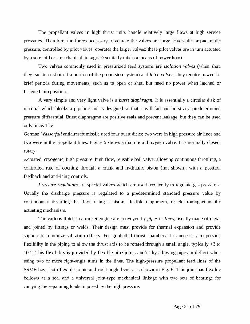
Page 52 of 79
The propellant valves in high thrust units handle relatively large flows at high service
pressures. Therefore, the forces necessary to actuate the valves are large. Hydraulic or pneumatic
pressure, controlled by pilot valves, operates the larger valves; these pilot valves are in turn actuated
by a solenoid or a mechanical linkage. Essentially this is a means of power boost.
Two valves commonly used in pressurized feed systems are isolation valves (when shut,
they isolate or shut off a portion of the propulsion system) and latch valves; they require power for
brief periods during movements, such as to open or shut, but need no power when latched or
fastened into position.
A very simple and very light valve is a burst diaphragm. It is essentially a circular disk of
material which blocks a pipeline and is designed so that it will fail and burst at a predetermined
pressure differential. Burst diaphragms are positive seals and prevent leakage, but they can be used
only once. The
German Wasserfall antiaircraft missile used four burst disks; two were in high pressure air lines and
two were in the propellant lines. Figure 5 shows a main liquid oxygen valve. It is normally closed,
rotary
Actuated, cryogenic, high pressure, high flow, reusable ball valve, allowing continuous throttling, a
controlled rate of opening through a crank and hydraulic piston (not shown), with a position
feedback and anti-icing controls.
Pressure regulators are special valves which are used frequently to regulate gas pressures.
Usually the discharge pressure is regulated to a predetermined standard pressure value by
continuously throttling the flow, using a piston, flexible diaphragm, or electromagnet as the
actuating mechanism.
The various fluids in a rocket engine are conveyed by pipes or lines, usually made of metal
and joined by fittings or welds. Their design must provide for thermal expansion and provide
support to minimize vibration effects. For gimballed thrust chambers it is necessary to provide
flexibility in the piping to allow the thrust axis to be rotated through a small angle, typically +3 to
10 °. This flexibility is provided by flexible pipe joints and/or by allowing pipes to deflect when
using two or more right-angle turns in the lines. The high-pressure propellant feed lines of the
SSME have both flexible joints and right-angle bends, as shown in Fig. 6. This joint has flexible
bellows as a seal and a universal joint-type mechanical linkage with two sets of bearings for
carrying the separating loads imposed by the high pressure.

Page 53 of 79
Sudden closing of valves can cause water hammer in the pipelines, leading to unexpected pressure
rises which can be destructive to propellant system components. An analysis of this water hammer
phenomenon will allow determination of the approximate maximum pressure. The friction of the
pipe and the branching of pipelines reduce this maximum pressure.
Water hammer can also occur when admitting the initial flow of high-pressure propellant into
evacuated pipes. The pipes are under vacuum to remove air and prevent the forming of gas bubbles
in the propellant flow, which can cause combustion problems. Many liquid rocket engines have
filters in their lines. This is necessary to prevent dirt, particles, or debris, such as small pieces from
burst diaphragms, from entering precision valves or regulators (where debris can cause a
malfunction) or from plugging small injection holes, which could cause hot streaks in the
combustion gases, in turn causing a thrust chamber failure. Occasionally a convergent-divergent
venture section, with a sonic velocity at its throat, is placed into one or both of the liquid propellant
lines. The merits are that it maintains constant flow and prevents pressure disturbances from
traveling upstream. This can include the propagating of chamber pressure oscillations or coupling
with thrust chamber combustion instabilities. The venture section can also help in minimizing some
water hammer effects in a system with multiple banks of thrust chambers.
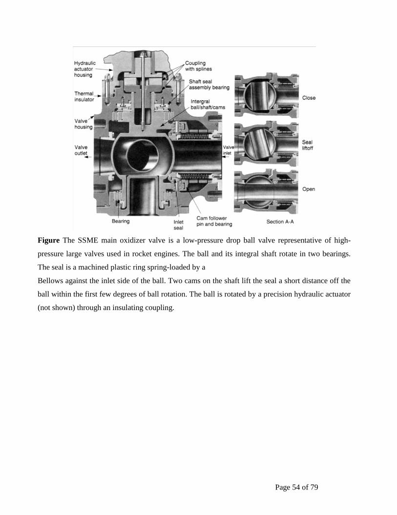
Page 54 of 79
Figure The SSME main oxidizer valve is a low-pressure drop ball valve representative of high-
pressure large valves used in rocket engines. The ball and its integral shaft rotate in two bearings.
The seal is a machined plastic ring spring-loaded by a
Bellows against the inlet side of the ball. Two cams on the shaft lift the seal a short distance off the
ball within the first few degrees of ball rotation. The ball is rotated by a precision hydraulic actuator
(not shown) through an insulating coupling.
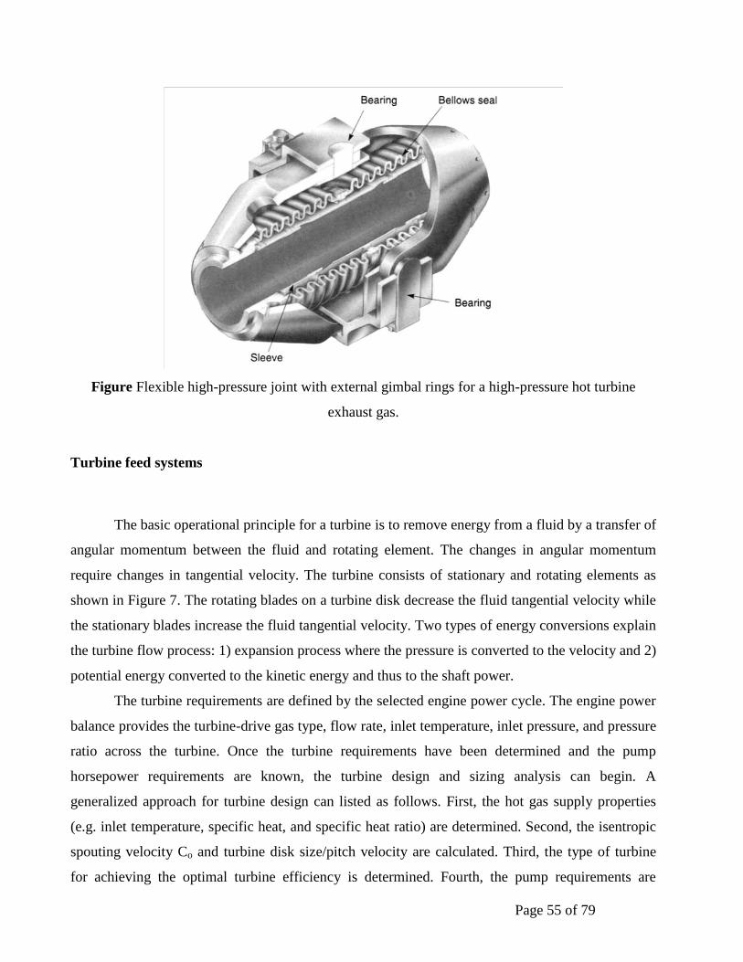
Page 55 of 79
Figure Flexible high-pressure joint with external gimbal rings for a high-pressure hot turbine
exhaust gas.
Turbine feed systems
The basic operational principle for a turbine is to remove energy from a fluid by a transfer of
angular momentum between the fluid and rotating element. The changes in angular momentum
require changes in tangential velocity. The turbine consists of stationary and rotating elements as
shown in Figure 7. The rotating blades on a turbine disk decrease the fluid tangential velocity while
the stationary blades increase the fluid tangential velocity. Two types of energy conversions explain
the turbine flow process: 1) expansion process where the pressure is converted to the velocity and 2)
potential energy converted to the kinetic energy and thus to the shaft power.
The turbine requirements are defined by the selected engine power cycle. The engine power
balance provides the turbine-drive gas type, flow rate, inlet temperature, inlet pressure, and pressure
ratio across the turbine. Once the turbine requirements have been determined and the pump
horsepower requirements are known, the turbine design and sizing analysis can begin. A
generalized approach for turbine design can listed as follows. First, the hot gas supply properties
(e.g. inlet temperature, specific heat, and specific heat ratio) are determined. Second, the isentropic
spouting velocity Co and turbine disk size/pitch velocity are calculated. Third, the type of turbine
for achieving the optimal turbine efficiency is determined. Fourth, the pump requirements are
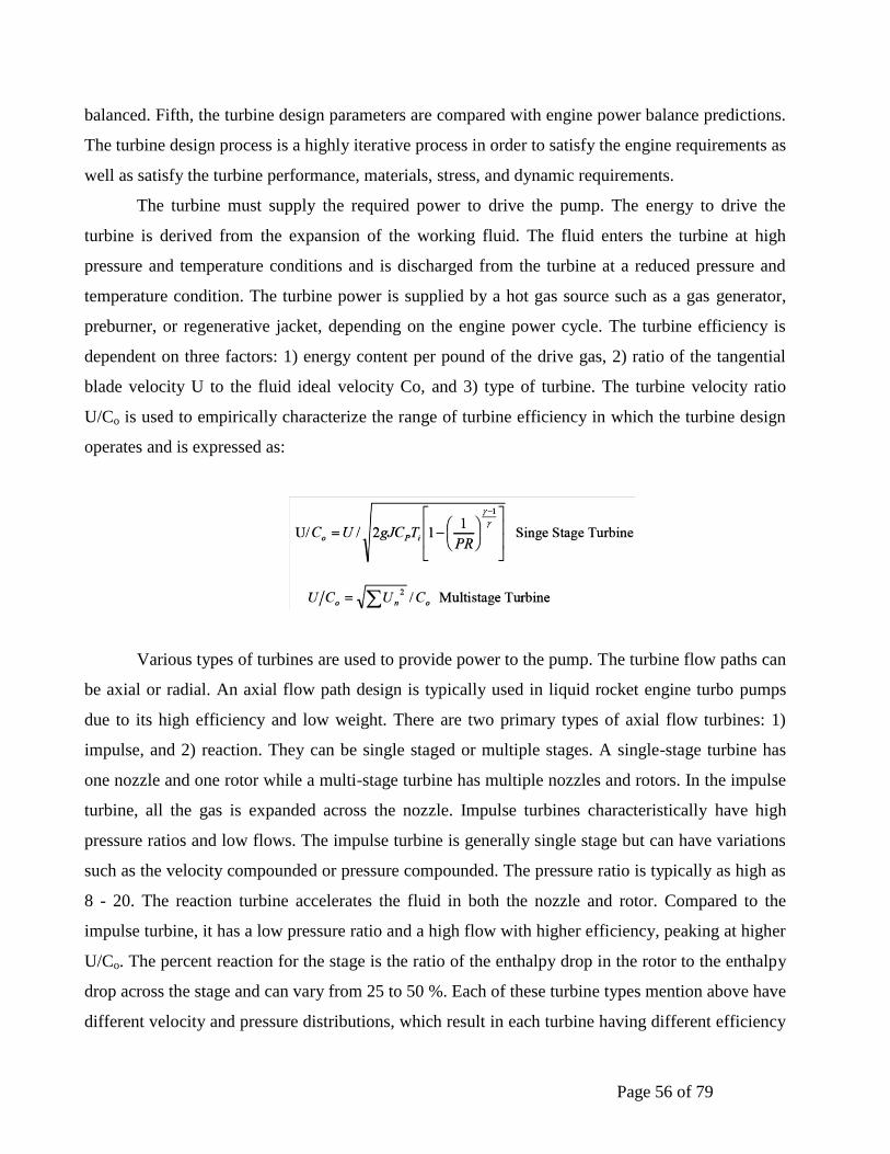
Page 56 of 79
balanced. Fifth, the turbine design parameters are compared with engine power balance predictions.
The turbine design process is a highly iterative process in order to satisfy the engine requirements as
well as satisfy the turbine performance, materials, stress, and dynamic requirements.
The turbine must supply the required power to drive the pump. The energy to drive the
turbine is derived from the expansion of the working fluid. The fluid enters the turbine at high
pressure and temperature conditions and is discharged from the turbine at a reduced pressure and
temperature condition. The turbine power is supplied by a hot gas source such as a gas generator,
preburner, or regenerative jacket, depending on the engine power cycle. The turbine efficiency is
dependent on three factors: 1) energy content per pound of the drive gas, 2) ratio of the tangential
blade velocity U to the fluid ideal velocity Co, and 3) type of turbine. The turbine velocity ratio
U/Co is used to empirically characterize the range of turbine efficiency in which the turbine design
operates and is expressed as:
Various types of turbines are used to provide power to the pump. The turbine flow paths can
be axial or radial. An axial flow path design is typically used in liquid rocket engine turbo pumps
due to its high efficiency and low weight. There are two primary types of axial flow turbines: 1)
impulse, and 2) reaction. They can be single staged or multiple stages. A single-stage turbine has
one nozzle and one rotor while a multi-stage turbine has multiple nozzles and rotors. In the impulse
turbine, all the gas is expanded across the nozzle. Impulse turbines characteristically have high
pressure ratios and low flows. The impulse turbine is generally single stage but can have variations
such as the velocity compounded or pressure compounded. The pressure ratio is typically as high as
8 - 20. The reaction turbine accelerates the fluid in both the nozzle and rotor. Compared to the
impulse turbine, it has a low pressure ratio and a high flow with higher efficiency, peaking at higher
U/Co. The percent reaction for the stage is the ratio of the enthalpy drop in the rotor to the enthalpy
drop across the stage and can vary from 25 to 50 %. Each of these turbine types mention above have
different velocity and pressure distributions, which result in each turbine having different efficiency

Page 57 of 79
characteristic as shown in Figure 8. Ultimately, the design selection is made to maximize the
turbine efficiency and minimize the weight compatible with the selected shaft speed.
Similar to the pump, there are some structural limits on the turbine. The tip speed structural
limit is generally based on the centrifugal pull that can be carried at the base of the blade airfoil for
the selected material. This is usually expressed as AaN2 (allowable annulus area times speed
squared) as a function of temperature. Other design limits relate to the performance and geometrical
design requirements.
During turbine development, various kinds of design problems can be encountered. These
problems can be placed in two general categories: 1) low cycle fatigue, and 2) high cycle fatigue.
The low cycle fatigue results from extreme temperature gradients on the hardware during operation.
The flow path hardware such as the inlet housing, turbine blades, and nozzles can experience low
cycle fatigue cracks. Other problems encountered are associated with the high cycle fatigue. The
dynamic environment of the turbine either from the aerodynamic environment or blade/vane
passing frequency can tune with turbine components during operation. Blades, vanes, or nozzles are
usually subject to high cycle fatigue cracking because of the severe dynamic environment. Dampers
can be incorporated into turbine blades at the platform or the blade tip/shroud to address blade
resonances.
Figure Elements of a Turbine
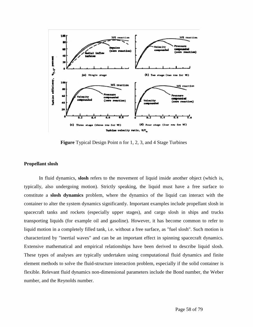
Page 58 of 79
Figure Typical Design Point n for 1, 2, 3, and 4 Stage Turbines
Propellant slosh
In fluid dynamics, slosh refers to the movement of liquid inside another object (which is,
typically, also undergoing motion). Strictly speaking, the liquid must have a free surface to
constitute a slosh dynamics problem, where the dynamics of the liquid can interact with the
container to alter the system dynamics significantly. Important examples include propellant slosh in
spacecraft tanks and rockets (especially upper stages), and cargo slosh in ships and trucks
transporting liquids (for example oil and gasoline). However, it has become common to refer to
liquid motion in a completely filled tank, i.e. without a free surface, as "fuel slosh". Such motion is
characterized by "inertial waves" and can be an important effect in spinning spacecraft dynamics.
Extensive mathematical and empirical relationships have been derived to describe liquid slosh.
These types of analyses are typically undertaken using computational fluid dynamics and finite
element methods to solve the fluid-structure interaction problem, especially if the solid container is
flexible. Relevant fluid dynamics non-dimensional parameters include the Bond number, the Weber
number, and the Reynolds number.

Page 59 of 79
Slosh is an important effect for spacecraft, ships, and some aircraft. Slosh was a factor in the recent
Falcon 1 second test flight anomaly, and has been implicated in various other spacecraft anomalies,
including a near-disaster with the Near Earth Asteroid Rendezvous (NEAR Shoemaker) satellite.
Spacecraft effects
Liquid slosh in microgravity is relevant to spacecraft, most commonly Earth-orbiting
satellites, and must take account of liquid surface tension which can alter the shape (and thus the
eigenvalues) of the liquid slug. Typically, a large part of the mass fraction of a satellite is liquid
propellant at/near Beginning of Life (BOL), and slosh can adversely affect satellite performance in
a number of ways. For example, propellant slosh can introduce uncertainty in spacecraft attitude
(pointing) which is often called jitter. Similar phenomena can cause pogo oscillation and can result
in structural failure of space vehicle. Another example is problematic interaction with the spacecraft
Attitude Control System (ACS), especially for spinning satellites which can suffer resonance
between slosh and nutation, or adverse changes to the rotational inertia.
Practical effects
Sloshing or shifting cargo, water ballast, or other liquid (e.g. from leaks or fire fighting) can
cause disastrous capsizing in ships due to free surface effect; this can also affect trucks and aircraft.
The effect of slosh is used to limit the bounce of a roller hockey ball. Water slosh can
significantly reduce the rebound height of a ball but some amounts of liquid seem to lead to a
resonance effect. Many of the balls for roller hockey commonly available contain water to reduce
the bounce height.
Shortly after it reached orbit in August 1969, NASA’s spin-stabilized Applications
Technology Satellite 5 (ATS5) began to wobble, sending the spacecraft into an unplanned flat spin
and crippling the mission. It was later found that this event was caused by excessive fuel slosh,
creating a long-standing concern about this phenomenon.
Spinning is a well-established method for stabilizing a spacecraft or launch vehicle upper
stage with a minimum of hardware, complexity, and expense. Fuel slosh reduces the rotational
kinetic energy of a spinning space vehicle, however, leading to a growing nutation (wobble) that
can undermine its gyroscopic stability. As the ATS5 mission demonstrated, failure to understand
the effect of fuel slosh can have serious consequences.
Page 60 of 79
Propellant Tanks
In liquid bipropellant rocket engine systems propellants are stored in one or more oxidizer
tanks and one or more fuel tanks; monopropellant rocket engine systems have, of course, only one
set of propellant tanks. There are also one or more high-pressure gas tanks, the gas being used to
pressurize the propellant tanks. Tanks can be arranged in a variety of ways, and the tank design can
be used to exercise some control over the change in the location of the vehicle's centre of gravity.
Typical arrangements are shown in Fig. 9. Because the propellant tank has to fly, its mass is at a
premium and the tank material is therefore highly stressed. Common tank materials are aluminium,
stainless steel, and titanium, alloy steel, and fibre-reinforced plastics with an impervious thin inner
liner of metal to prevent leakage through the pores of the fibre reinforced walls.
The extra volume of gas above the propellant in sealed tanks is called ullage. It is necessary
space that allows for thermal expansion of the propellant liquids, for the accumulation of gases that
were originally dissolved in the propellant, or for gaseous products from slow reactions within the
propellant during storage. Depending on the storage temperature range, the propellants' coefficient
of thermal expansion, and the particular application, the ullage volume is usually between 3 and
10% of the tank volume. Once propellant is loaded into a tank, the ullage volume (and, if it is
sealed, also its pressure) will change as the bulk temperature of the propellant varies.
The expulsion efficiency of a tank and/or propellant piping system is the amount of
propellant expelled or available divided by the total amount of propellant initially present. Typical
values are 97 to 99.7%. The losses are unavailable propellants that are trapped in grooves or corners
of pipes, fittings, and valves, are wetting the walls, retained by surface tension, or caught in
instrument taps. This residual propellant is not available for combustion and must be treated as
inert mass, causing the vehicle mass ratio to decrease slightly. In the design of tanks and piping
systems, an effort is made to minimize the residual propellant.
The optimum shape of a propellant tank (and also a gas pressurizing tank) is spherical,
because for a given volume it results in a tank with the least weight. Small spherical tanks are often
used with reaction control engine systems, where they can be packaged with other vehicle
equipment. Unfortunately, the larger spheres, which are needed for the principal propulsion
systems, are not very efficient for using the space in a vehicle. These larger tanks are often made
integral with the vehicle fuselage or wing. Most are cylindrical with half ellipses at the ends, but
Page 61 of 79
they can be irregular in shape. A more detailed discussion of tank pressurization is given in the next
section.
Cryogenic propellants cool the tank wall temperature far below the ambient air temperature.
This causes condensation of moisture on the outside of the tank and usually also formation of ice
during the period prior to launch. The ice is undesirable, because it increases the vehicle inert mass
and can cause valves to malfunction. Also, as pieces of ice are shaken off or break off during the
initial flight, these pieces can damage the vehicle; for example, the ice from the Shuttle's cryogenic
tank can hit the orbiter vehicle.
For an extended storage period, cryogenic tanks are usually thermally insulated; porous
external insulation layers have to be sealed to prevent moisture from being condensed inside the
insulation layer. With liquid hydrogen it is possible to liquefy or solidify the ambient air on the
outside of the fuel tank.
Even with heavy insulation and low-conductivity structural tank supports, it is not possible to
prevent the continuous evaporation of the cryogenic fluid. Even with good thermal insulation, all
cryogenic propellants evaporate slowly during storage and therefore cannot be kept in a vehicle for
more than perhaps a week without refilling of the tanks. For vehicles that need to be stored or to
operate for longer periods, a storable propellant combination must be used.
Prior to loading very cold cryogenic propellant into a flight tank, it is necessary to remove or
evacuate the air to avoid forming solid air particles or condensing any moisture as ice. These frozen
particles would plug up injection holes, cause valves to freeze shut, or prevent valves from being
fully closed. Tanks, piping, and valves need to be chilled or cooled down before they can contain
cryogenic liquid without excessive bubbling. This is usually done by letting the initial amount of
cryogenic liquid absorb the heat from the relatively warm hardware. This initial propellant is
vaporized and vented through appropriate vent valves.
If the tank or any segment of piping containing low-temperature cryogenic liquid is sealed
for an extended period of time, heat from ambient-temperature hardware will result in evaporation
and this will greatly raise the pressure until it exceeds the strength of the container. This self-
pressurization will cause a failure, usually a major leak or even an explosion. All cryogenic tanks
and piping systems are therefore vented during storage on the launch pad, equipped with pressure
safety devices (such as burst diaphragms or relief valves), and the evaporated propellant is allowed
to escape from its container. For long-term storage of cryogenic propellants in space vacuum (or on
the ground) some form of a powered refrigeration system is needed to recon dense the vapours and
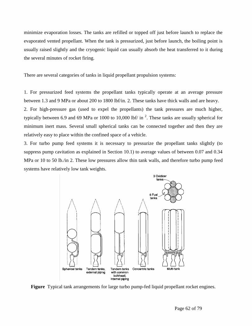
Page 62 of 79
minimize evaporation losses. The tanks are refilled or topped off just before launch to replace the
evaporated vented propellant. When the tank is pressurized, just before launch, the boiling point is
usually raised slightly and the cryogenic liquid can usually absorb the heat transferred to it during
the several minutes of rocket firing.
There are several categories of tanks in liquid propellant propulsion systems:
1. For pressurized feed systems the propellant tanks typically operate at an average pressure
between 1.3 and 9 MPa or about 200 to 1800 lbf/in. 2. These tanks have thick walls and are heavy.
2. For high-pressure gas (used to expel the propellants) the tank pressures are much higher,
typically between 6.9 and 69 MPa or 1000 to 10,000 lbf/ in 2. These tanks are usually spherical for
minimum inert mass. Several small spherical tanks can be connected together and then they are
relatively easy to place within the confined space of a vehicle.
3. For turbo pump feed systems it is necessary to pressurize the propellant tanks slightly (to
suppress pump cavitation as explained in Section 10.1) to average values of between 0.07 and 0.34
MPa or 10 to 50 lb./in 2. These low pressures allow thin tank walls, and therefore turbo pump feed
systems have relatively low tank weights.
Figure Typical tank arrangements for large turbo pump-fed liquid propellant rocket engines.
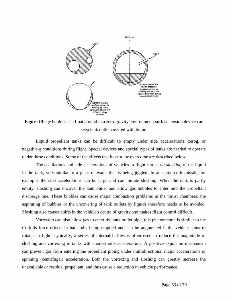
Page 63 of 79
Figure Ullage bubbles can float around in a zero-gravity environment; surface tension device can
keep tank outlet covered with liquid.
Liquid propellant tanks can be difficult to empty under side accelerations, zerog, or
negative-g conditions during flight. Special devices and special types of tanks are needed to operate
under these conditions. Some of the effects that have to be overcome are described below.
The oscillations and side accelerations of vehicles in flight can cause sloshing of the liquid
in the tank, very similar to a glass of water that is being jiggled. In an antiaircraft missile, for
example, the side accelerations can be large and can initiate sloshing. When the tank is partly
empty, sloshing can uncover the tank outlet and allow gas bubbles to enter into the propellant
discharge line. These bubbles can cause major combustion problems in the thrust chambers; the
aspirating of bubbles or the uncovering of tank outlets by liquids therefore needs to be avoided.
Sloshing also causes shifts in the vehicle's centre of gravity and makes flight control difficult.
Vortexing can also allow gas to enter the tank outlet pipe; this phenomenon is similar to the
Coriolis force effects in bath tubs being emptied and can be augmented if the vehicle spins or
rotates in fight. Typically, a series of internal baffles is often used to reduce the magnitude of
sloshing and vortexing in tanks with modest side accelerations. A positive expulsion mechanism
can prevent gas from entering the propellant piping under multidirectional major accelerations or
spinning (centrifugal) acceleration. Both the vortexing and sloshing can greatly increase the
unavailable or residual propellant, and thus cause a reduction in vehicle performance.
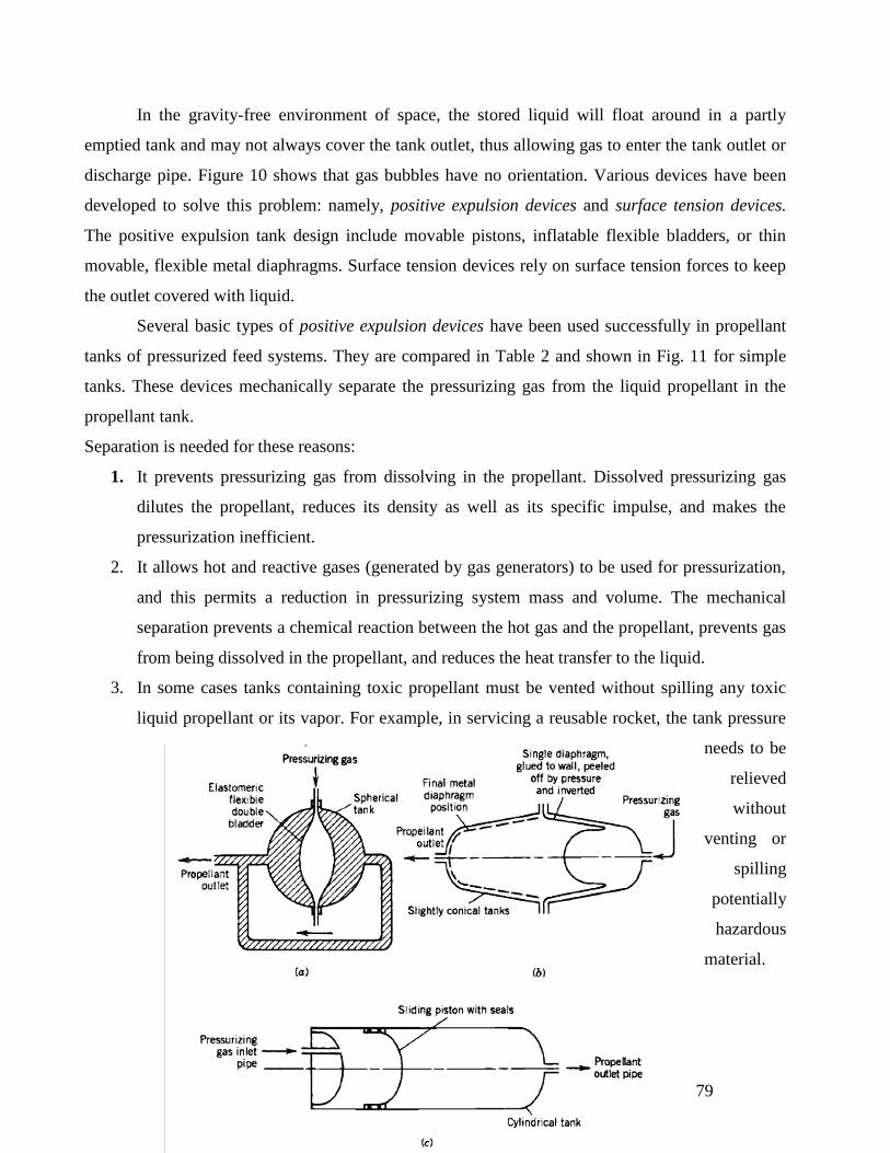
Page 64 of 79
In the gravity-free environment of space, the stored liquid will float around in a partly
emptied tank and may not always cover the tank outlet, thus allowing gas to enter the tank outlet or
discharge pipe. Figure 10 shows that gas bubbles have no orientation. Various devices have been
developed to solve this problem: namely, positive expulsion devices and surface tension devices.
The positive expulsion tank design include movable pistons, inflatable flexible bladders, or thin
movable, flexible metal diaphragms. Surface tension devices rely on surface tension forces to keep
the outlet covered with liquid.
Several basic types of positive expulsion devices have been used successfully in propellant
tanks of pressurized feed systems. They are compared in Table 2 and shown in Fig. 11 for simple
tanks. These devices mechanically separate the pressurizing gas from the liquid propellant in the
propellant tank.
Separation is needed for these reasons:
1. It prevents pressurizing gas from dissolving in the propellant. Dissolved pressurizing gas
dilutes the propellant, reduces its density as well as its specific impulse, and makes the
pressurization inefficient.
2. It allows hot and reactive gases (generated by gas generators) to be used for pressurization,
and this permits a reduction in pressurizing system mass and volume. The mechanical
separation prevents a chemical reaction between the hot gas and the propellant, prevents gas
from being dissolved in the propellant, and reduces the heat transfer to the liquid.
3. In some cases tanks containing toxic propellant must be vented without spilling any toxic
liquid propellant or its vapor. For example, in servicing a reusable rocket, the tank pressure
needs to be
relieved
without
venting or
spilling
potentially
hazardous
material.
Page 65 of 79
A piston expulsion device permits the centre of gravity (CG) to be accurately controlled and its
location to be known. This is important in rockets with high side accelerations such as antiaircraft
missiles or space defines missiles, where the thrust vector needs to go through the CG; if the CG is
not well known, unpredictable turning moments may be imposed on the vehicle. A piston also
prevents sloshing or vortexing.
Surface tension devices use capillary attraction for supplying liquid propellant to the tank
outlet pipe. These devices (see Fig. 10) are often made of very fine (300 mesh) stainless steel wire
woven into a screen and formed into tunnels or other shapes. These screens are located near the tank
outlet and, in some tanks, the tubular galleries are designed to connect various parts of the tank
volume to the outlet pipe sump. These devices work best in a relatively low-acceleration
environment, when surface tension forces can overcome the inertia forces.
The combination of surface tension screens, baffles, sumps, and traps is called a propellant
management device. Although not shown in any detail, they are included inside the propellant tanks
of Fig. 10.
The two SRBs provide 71.4 percent of the main thrust needed to lift the Space Shuttle off the
launch pad. Each booster has a thrust of approximately 3,300,000 pounds (14,685 kilonewtons) at
Figure Three concepts of propellant tanks with positive expulsion: (a) inflatable dual bladder; (b) rolling, peeling
diaphragm; (c) sliding piston. As the propellant volume expands or contracts with changes in ambient temperature, the
piston or diaphragm will also move slightly and the ullage volume will change during storage.
Page 66 of 79
launch and help lift the Shuttle to an altitude of about 150,000 feet, or 28 miles (50 kilometres). The
SRBs burn for approximately two minutes and are then jettisoned from the Shuttle. During their
decent, three parachutes are deployed from the top of each SRB to allow for a safe splashdown in
the Atlantic Ocean, roughly 141 miles (260 kilometres) downrange from Kennedy Space Centre.
Both SRBs are equipped with special floatation devices that allow them to float once they splash
down. Flotation is aided by the large air pocket trapped inside when the empty rocket booster
crashes down tail first into the water. Two specially designed and equipped NASA boats, the
Liberty Star and Freedom Star, are deployed to retrieve both SRBs and return them to the Kennedy
Space Centre. Once they return to the Space Centre, they are disassembled and sent to be
reprocessed so they can be used again.
• These booster rockets are the largest solid fuel motors ever used in space flight, and are also the
first designed to be reusable.
• Each SRB weighs approximately 1,300,000 pounds (589,670 kilograms) at launch with roughly
85 percent being the weight of the solid fuel itself.
• The solid fuel, or propellant, is a mixture of ammonium perchlorate, aluminium, and iron
oxide.
• The SRBs burn for approximately two minutes and are then jettisoned. During their descent, three
main parachutes are deployed from the top of each SRB to allow for a safe splashdown in the
Atlantic Ocean.

Page 67 of 79
Solid Rocket Boosters
The solid rocket boosters (SRB) operate in parallel with the main engines for the first two minutes of
flight to provide the additional thrust needed for the orbiter to escape the gravitational pull of the
Earth. At an altitude of approximately 45 km (24 nautical miles), the boosters separate from the
orbiter/external tank, descend on parachutes, and land in the Atlantic Ocean. They are recovered by
ships, returned to land, and refurbished for reuse. The boosters also assist in guiding the entire
vehicle during initial ascent. Thrust of both boosters is equal to 5,300,000 lb.
In addition to the solid rocket motor, the booster contains the structural, thrust vector control,
separation, recovery, and electrical and instrumentation subsystems.
The solid rocket motor is the largest solid propellant motor ever developed for space flight and the
first built to be used on a manned craft. The huge motor is composed of a segmented motor case
loaded with solid propellants, an ignition system, a movable nozzle, and the necessary
instrumentation and integration hardware.
The SRBs separate from Columbia about two minutes after the first launch of the Shuttle Program.
Each solid rocket motor contains more than 450,000 kg (1,000,000 lb.) of propellant, which requires
an extensive mixing and casting operation at a plant in Utah. The propellant is mixed in 600 gallon
bowls located in three different mixer buildings. The propellant is then taken to special casting
buildings and poured into the casting segments.
Thrust at lift-off
1,202,020 kilograms (2,650,000 pounds)
Propellant Properties
Atomized aluminium powder (fuel: 16%) Ammonium perchlorate (oxidizer: 69.83%) Iron
oxide powder (catalyst: 0.17%)
Polybutadiene acrylic acid acrylamide (binder: 12%) Epoxy curing agent (2 %)
Weight
Empty: 87,543 kilograms (193,000 pounds) Propellant: 502,126 kilograms (1,107,000 pounds)
Gross: 589,670 kilograms (1,300,000 pounds)
Cured propellant looks and feels like a hard rubber typewriter eraser. The combined polymer and its
curing agent is a synthetic rubber. Flexibility of the propellant is controlled by the ratio of binder to
curing agent and the solid ingredients, namely oxidizer and aluminium. The solid fuel is actually
powdered aluminium—a form similar to the foil wraps in your kitchen—mixed with oxygen
provided by a chemical called ammonium perchlorate.

Page 68 of 79
Unit 5
Electric Propulsion
Electric propulsion (EP) encompass a broad variety of strategies for achieving very high exhaust
velocities in order to reduce the total propellant burden and corresponding launch mass of present
and future space transportation systems.
Limitations of Chemical Rockets
Chemical rocket: exhaust ejection velocity intrinsically limited by the propellant-oxidizer reaction
Larger velocity increment of the spacecraft could be obtained only with a larger ejected mass flow.
Mission practical limitation: exceedingly large amount of propellant that needs to be stored aboard.
• Chemical rockets: Energy limited
• Limited to energy contained within propellants they carry
• High power (W=J/s) due to rapid conversion of energy
• Electric systems: Power limited
• No limit to energy added to propellant (in theory)
• However, rate of conversion of energy to power limited by mass of conversion
equipment which must be carried, M electrical
• Possible to achieve very high exhaust velocities at cost of high power consumption
• Electric propulsion broadly defined as acceleration of propellants by:
• Electrical heating (thermal rocket)
• Electric body forces
• Magnetic body forces
These techniques group broadly into three categories:
• Electro thermal propulsion, wherein the propellant is electrically heated, then expanded
thermodynamically through a nozzle.
• Electrostatic propulsion, wherein ionized propellant particles are accelerated through an
electric field.
• Electromagnetic propulsion, wherein current driven through a propellant plasma interacts
with an internal or external magnetic field to provide a stream-wise body force.
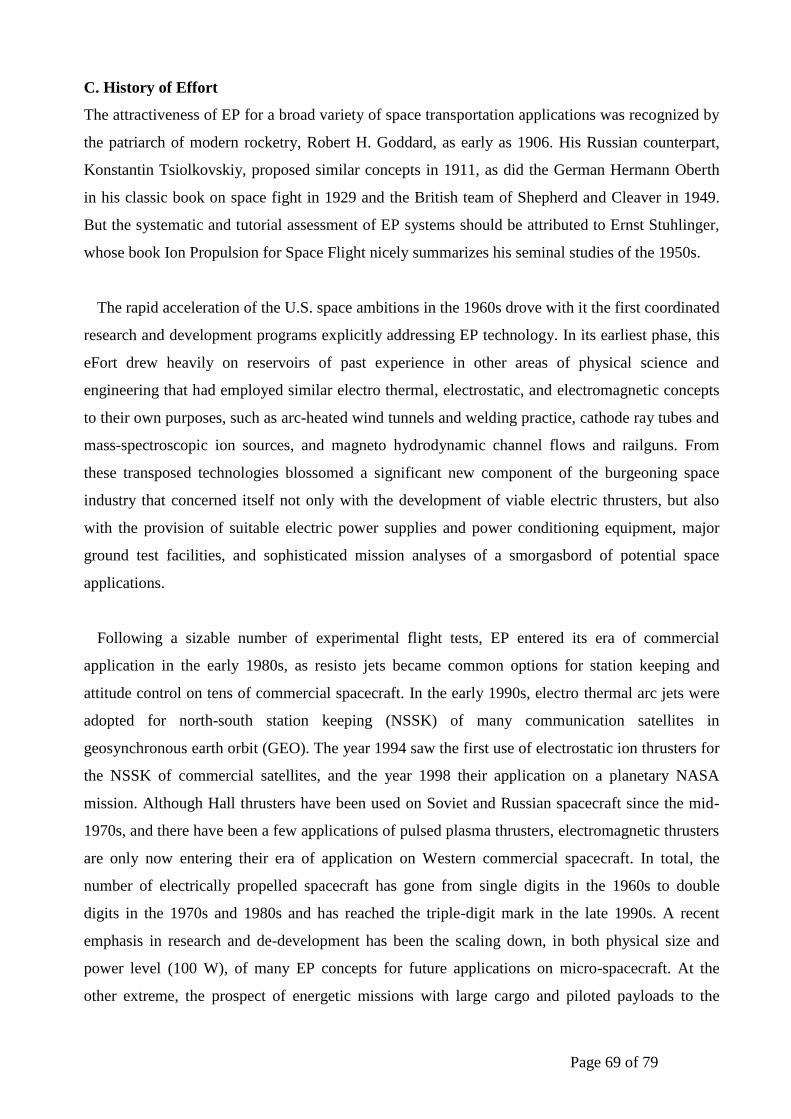
Page 69 of 79
C. History of Effort
The attractiveness of EP for a broad variety of space transportation applications was recognized by
the patriarch of modern rocketry, Robert H. Goddard, as early as 1906. His Russian counterpart,
Konstantin Tsiolkovskiy, proposed similar concepts in 1911, as did the German Hermann Oberth
in his classic book on space fight in 1929 and the British team of Shepherd and Cleaver in 1949.
But the systematic and tutorial assessment of EP systems should be attributed to Ernst Stuhlinger,
whose book Ion Propulsion for Space Flight nicely summarizes his seminal studies of the 1950s.
The rapid acceleration of the U.S. space ambitions in the 1960s drove with it the first coordinated
research and development programs explicitly addressing EP technology. In its earliest phase, this
eFort drew heavily on reservoirs of past experience in other areas of physical science and
engineering that had employed similar electro thermal, electrostatic, and electromagnetic concepts
to their own purposes, such as arc-heated wind tunnels and welding practice, cathode ray tubes and
mass-spectroscopic ion sources, and magneto hydrodynamic channel flows and railguns. From
these transposed technologies blossomed a significant new component of the burgeoning space
industry that concerned itself not only with the development of viable electric thrusters, but also
with the provision of suitable electric power supplies and power conditioning equipment, major
ground test facilities, and sophisticated mission analyses of a smorgasbord of potential space
applications.
Following a sizable number of experimental flight tests, EP entered its era of commercial
application in the early 1980s, as resisto jets became common options for station keeping and
attitude control on tens of commercial spacecraft. In the early 1990s, electro thermal arc jets were
adopted for north-south station keeping (NSSK) of many communication satellites in
geosynchronous earth orbit (GEO). The year 1994 saw the first use of electrostatic ion thrusters for
the NSSK of commercial satellites, and the year 1998 their application on a planetary NASA
mission. Although Hall thrusters have been used on Soviet and Russian spacecraft since the mid-
1970s, and there have been a few applications of pulsed plasma thrusters, electromagnetic thrusters
are only now entering their era of application on Western commercial spacecraft. In total, the
number of electrically propelled spacecraft has gone from single digits in the 1960s to double
digits in the 1970s and 1980s and has reached the triple-digit mark in the late 1990s. A recent
emphasis in research and de-development has been the scaling down, in both physical size and
power level (100 W), of many EP concepts for future applications on micro-spacecraft. At the
other extreme, the prospect of energetic missions with large cargo and piloted payloads to the
Page 70 of 79
planets.
II. ELECTROTHERMAL PROPULSION
A. Overview
Electro thermal propulsion comprises all techniques whereby the propellant is electrically heated in
some chamber and then expanded through a suitable nozzle to convert its thermal energy to a
directed stream that delivers reactive thrust power to the vehicle. Three subclasses of this family
may be denoted in terms of the physical details of the propellant heating:
1. Resist jets, wherein heat is transferred to the propellant from some solid surface, such as
the chamber wall or a heater coil
2. Arc jets, wherein the propellant is heated by an electric arc driven through it
3. Inductively and radioactively heated devices, wherein some form of electrodeless discharge or
high-frequency radiation heats the flow
Each of these strategies relieves some of the intrinsic limitations of the chemical rocket in the
sense that the propellant species may be selected for its propitious physical properties
independently of any combustion chemistry, but heat transfer constraints and frozen flow losses
(losses due to unremunerated) remain endemic.
The gross performance of any electro thermal thruster can be crudely forecast by means of a
rudimentary one-dimensional energy argument that limits the exhaust speed of the flow from a
fully expanded nozzle to e 2cp Tc, where cp is the specific heat at constant pressure per unit mass of
the propellant and Tc is the maximum tolerable chamber temperature. Propellants of the lowest
molecular weight thus seem preferable, and indeed hydrogen might at first glance appear optimum,
but in practice its frozen propensities and difficulty of storage compromise its attractiveness. More
complex molecular gases such as ammonia and hydrazine, which dissociate into fairly low
efFective molecular weights and heat gas mixtures in the chamber, are currently more popular, but
in these cases also, frozen kinetics in the nozzle remain important to performance.
Page 71 of 79
B. Resisto jets
In the resisto jet subclass of devices, chamber temperature is necessarily limited by the materials of
the walls and/or heater coils to some 3000 K or less, and hence the exhaust velocities, even with
equilibrated hydrogen, cannot exceed 10,000 m/sec, which is nonetheless a factor of two or three
beyond that of the best chemical rockets. In con-temporary practice, lower performance but more
readily space storable propellants, such as hydrazine and ammonia, along with bio waste gases
such as water vapour and carbon dioxide, are more commonly employed because of their overall
system advantages.
Beyond the frozen kinetics, the major practical challenge facing resisto jet technology is
retaining the in-tegrity of the insulator and heater surfaces at the very high temperatures the
concept demands, while still minimizing the viscous and radiative heat losses that further de-crease
thruster efficiency. Since the mid-1960s, many configurations of resisto jet have been conceived,
researched, and developed to optimize these processes, and a few, such as the flight-ready module
shown schematically and in the photograph in Fig. 1, have evolved to practical space thrusters and
been deployed on suitable missions. A typical resisto jet uses catalytically decomposed hydrazine
as its propellant and achieves an exhaust velocity of 3500 m/sec and a thrust of 0.3 N at an
efficiency of 80% when operating at a power level of 750 W.
From a system point of view, resisto jets are particularly attractive because they readily lend
themselves to integration with previously developed and commonly used propellant storage and
flow management systems for hydrazine monopropellant thrusters. Another advantage is their low
operational voltage, which, unlike that in other EP systems, does not require complex power
processing. For these reasons, and the fact that satellites in GEO often have excess electrical
power, resistors were among the EP options to be used for the NSSK of communication satellites.
While the earliest use of resistojets in space dates to 1965 (the Air Force Vela satellites), their
adoption on commercial spacecraft did not start until the 1980 launch of the satellites in the
INTELSAT-V series. A more recent application has been for orbit insertion, attitude control, and
deorbit of LEO satellites, including the 72 satellites in the Iridium constellation.
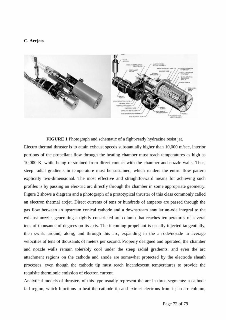
Page 72 of 79
C. Arcjets
FIGURE 1 Photograph and schematic of a fight-ready hydrazine resist jet.
Electro thermal thruster is to attain exhaust speeds substantially higher than 10,000 m/sec, interior
portions of the propellant flow through the heating chamber must reach temperatures as high as
10,000 K, while being re-strained from direct contact with the chamber and nozzle walls. Thus,
steep radial gradients in temperature must be sustained, which renders the entire flow pattern
explicitly two-dimensional. The most effective and straightforward means for achieving such
profiles is by passing an elec-tric arc directly through the chamber in some appropriate geometry.
Figure 2 shows a diagram and a photograph of a prototypical thruster of this class commonly called
an electron thermal arcjet. Direct currents of tens or hundreds of amperes are passed through the
gas flow between an upstream conical cathode and a downstream annular an-ode integral to the
exhaust nozzle, generating a tightly constricted arc column that reaches temperatures of several
tens of thousands of degrees on its axis. The incoming propellant is usually injected tangentially,
then swirls around, along, and through this arc, expanding in the an-ode/nozzle to average
velocities of tens of thousands of meters per second. Properly designed and operated, the chamber
and nozzle walls remain tolerably cool under the steep radial gradients, and even the arc
attachment regions on the cathode and anode are somewhat protected by the electrode sheath
processes, even though the cathode tip must reach incandescent temperatures to provide the
requisite thermionic emission of electron current.
Analytical models of thrusters of this type usually represent the arc in three segments: a cathode
fall region, which functions to heat the cathode tip and extract electrons from it; an arc column,
Page 73 of 79
wherein ohmic heating hboxsustains the necessary ionization against interior recombination and
radiation losses; and an anode fall region, wherein the arc terminates in a diffuse annular
attachment on the diverg-ing nozzle wall, depositing thermal electron energy into the body of the
thruster. Heating of the propellant actually occurs in two important modes: by direct passage of a
core portion of the flow through the arc itself, and by conduc-tion and convection to the outer flow
from the chamber and nozzle walls, which themselves have been heated by radi-ation from the arc
column and by the anode attachment. This latter, regenerative component rescues the efficiency of
the thruster somewhat from the detrimental frozen flow losses associated with the failure of the
hottest portion of the core flow to recover much of the energy invested in its ionization and
dissociation. Aside from these frozen flow losses, the efficiency also suffers from viscous effects,
non-uniform heat addition across the flow, and heat deposition in the near-electrode regions due to
voltage drops in the electrode sheaths.
Arc jets on contemporary operational fights typically use catalytically decomposed hydrazine as
propellant and operate at a power level of about 1.5 kW with an exhaust velocity between 5000 and
6000 m/sec and an efficiency up to 40%. While ammonia, by virtue of its lower molecular mass,
can offer an exhaust velocity as high as 9000 m/sec at the same power levels, the associated
complexity of the mass feeding system favors the use of hydrazine. Since these arc jets operate at a
voltage of about 100 V, which is generally higher than the spacecraft bus voltage, dedicated power
processing units, whose mass can exceed that of the dry propulsion system, are required.
Starting with the First of the Telstar-4 series of GEO communication satellites launched in 1993,
hydrazine arc jets have quickly gained acceptance as viable propulsion options for NSSK. They
represent the second evolutionary step, after resisto jets, in the use of EP systems and offer
substantial propellant mass savings over all previous monopropellant propulsion options. Although
a re-cent test fight of a 30-kW ammonia arc jet (on the Air Force ESSEX spacecraft) has
demonstrated the potential of this higher power class of electrothermal propulsion for more thrust-
intensive missions such as orbit transfers and primary propulsion manoeuvres, the difficulty of
providing such high power in space, combined with the lifetime-limiting problems of electrode
erosion and whickering have so far delayed such applications.
D. Inductively and Radioactively Heated Devices
The most vulnerable elements of direct current arc jets are the electrodes that transmit the high
currents from the external circuit to the arc plasma, and their erosion ultimately limits the
operational lifetime of these thrusters. In efforts to alleviate this basic problem, a number of more
ex-otic concepts for electro thermal propulsion have been pro-posed and implemented, wherein the
propellant is ionized and heated by means of some form of electrodeless dis-charge. These have
Page 74 of 79
varied widely in power levels, geometries, propellant types, and densities and have utilized ap-
plied frequencies ranging from low radio frequency (RF) to the microwave bands. In all cases, the
strategy is to heat the free electron component of the ionized propellant by means of an applied
oscillating electromagnetic Feld and then to rely either on am bipolar diffusion to direct the ions
and neutrals along an appropriate exhaust channel (inductive thrusters) or on collisional and
radiative heating of the neutral component by a sustained plasma upstream of the throat of a
diverging nozzle (microwave thrusters). Devices of this class are thus hybrid electro thermal and
electrostatic and, indeed, since some of them also employ magnetic Felds to confine and direct the
flow, may actually embody all three classes of interaction.
Early enthusiasm for this class of accelerators was necessarily tempered by the relatively low
efficiency of RF and microwave power generation technologies of that time, which would have
transcribed into intolerably massive space power supplies. More recent advances in solid-state
power processing have revived some of these concepts, although none has yet been fight-tested.
The most mature of these concepts is currently a microwave electrothermal thruster that operates
with hydrogen, nitrogen, or ammonia at exhaust velocities ranging between 4000 m/sec and 12,000
m/sec and efficiencies as high as 60%, excluding the efficiency of the microwave source. The
microwave electro thermal thruster seems particularly amenable to scaling to low powers. While
most of the recent development has been at the kilowatt level, scaled-down prototypes operating
efficiently at 100 W and below have also been developed.
III. ELECTROSTATIC PROPULSION
A. Basic Elements
The fundamental thermal limitations on attainable exhaust speeds and lifetimes associated with the
heating and expansion processes of electro thermal accelerators can be categorically circumvented
if the propellant is directly accelerated by an external body force. The simplest such device, in
concept, is the ion thruster, wherein a beam of atomic ions is accelerated by a suitable electric Feld
and subsequently neutralized by an equal flux of free electrons. The essential elements of such a
thruster are sketched in Fig. 3, where a collisionless stream of positive atomic ions, liberated from
some source, is accelerated by an electro-static Feld established between the source surface and a
suitable permeable grid. Downstream of this region, electrons from another source join the ion
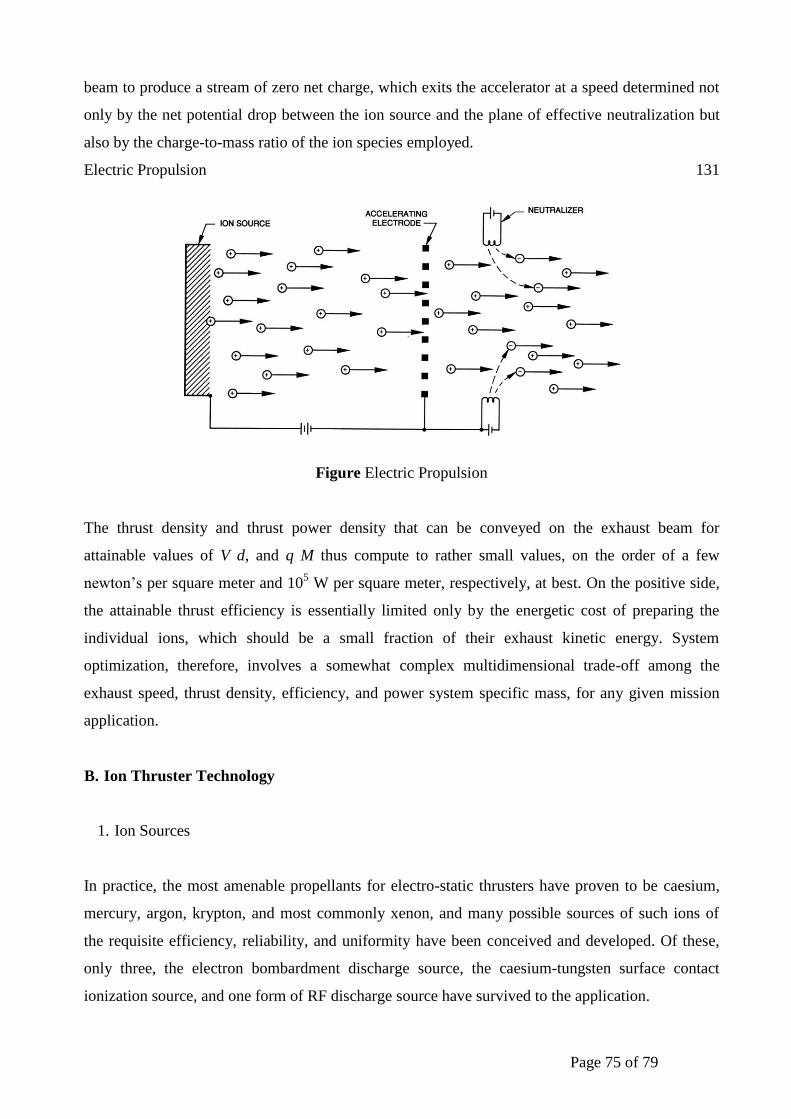
Page 75 of 79
beam to produce a stream of zero net charge, which exits the accelerator at a speed determined not
only by the net potential drop between the ion source and the plane of effective neutralization but
also by the charge-to-mass ratio of the ion species employed.
Electric Propulsion 131
Figure Electric Propulsion
The thrust density and thrust power density that can be conveyed on the exhaust beam for
attainable values of V d, and q M thus compute to rather small values, on the order of a few
newton’s per square meter and 105 W per square meter, respectively, at best. On the positive side,
the attainable thrust efficiency is essentially limited only by the energetic cost of preparing the
individual ions, which should be a small fraction of their exhaust kinetic energy. System
optimization, therefore, involves a somewhat complex multidimensional trade-off among the
exhaust speed, thrust density, efficiency, and power system specific mass, for any given mission
application.
B. Ion Thruster Technology
1. Ion Sources
In practice, the most amenable propellants for electro-static thrusters have proven to be caesium,
mercury, argon, krypton, and most commonly xenon, and many possible sources of such ions of
the requisite efficiency, reliability, and uniformity have been conceived and developed. Of these,
only three, the electron bombardment discharge source, the caesium-tungsten surface contact
ionization source, and one form of RF discharge source have survived to the application.

Page 76 of 79
The essential elements of the bombardment sources are some form of cylindrical discharge
chamber containing a centreline cathode that emits electrons, a surrounding anode shell, and a
permeating azimuthal and radial magnetic Feld that constrains the electrons to gyrate within the
chamber long enough to ionize the injected propellant gas and to direct it, once ionized, to
extractor and accelerator grids downstream. One contemporary implementation of such a chamber
is shown in Fig. 4. This particular device employs a hollow cathode electron source, wherein is
sustained a secondary discharge that facilitates electron emission from the interior walls of the
cathode cavity. The magnetic Feld permeating the entire chamber is provided by three ring
magnets, empirically configured to establish a grossly diverging but doubly cusped Feld pattern
that optimizes the discharge for ionization and ion extraction purposes. The magnitude of this Feld
is adjusted in concert with the anode-cathode voltage differential to maximize the ionization
efficiency and discharge stability while minimizing the production of doubly charged ions, which
would be out of focus in the accelerator gap and thus tend to erode the grids through high-energy
sputtering. Typical values for xenon and mercury propellants would be in the regimes of 0. 25 T
and 30 V, respectively. Slightly different chamber configurations and Feld values have also been
used successfully.
Contact ion sources rely on the difference between the electronic work function of a metallic
surface and the ionization potential of alkali vapours to ionize the latter on contact with the former.
Very few metal- alkali combinations have this requisite positive voltage differential, and of these
the combination of tungsten and caesium provides
FIGURE Ring-cup ion thruster. [Courtesy of Colorado State University and NASA

Page 77 of 79
The most common implementation has been to force hot caesium vapour through a porous tungsten
wafer to enhance surface contact, but problems in degradation of wafer porosity and condensation
of caesium vapour have tended to compromise the ionization efficiency and lifetime of these
sources.
The RF ionization sources currently favoured in Western Europe are similar in principle and
configuration to the U.S. electron bombardment sources, except that the discharge is inductively
driven RF rather than directly coupled dc. While the efficiency and lifetime of these RF sources
seem competitive, they entail the complication of RF modules in their power processing
equipment. In Japan, another cathode less ion thruster concept has been developed that uses a
microwave source to create and sustain the plasma through electron cyclotron resonance (ECR)
and offers some system and lifetime advantages
2. Accelerator Grids
In virtually all classes of ion thruster, the positive ions are extracted from the source and
accelerated downstream by a system of grids configured to achieve the desired exhaust velocity
with minimum beam impingement. In U.S. bombardment engines, for example, a double grid
configuration is usually dished downstream as shown in Fig. 4 to improve its mechanical and
thermal stability against distortion. The upstream grid is maintained at a higher positive potential
than required by the desired exhaust speed in order to enhance the ion extraction process and
increase the space-charge-limited current density that can be sustained. The downstream grid then
reduces the exhaust plane potential to the desired value. The scheme has the advantages of higher
beam density at a given net voltage and of reducing electron back streaming from the neutralized
beam downstream.
The grid perforations are configured analytically and empirically to focus the ion stream into an
array of beamlets that pass through with minimum impingement. In this process, the downstream
surface of the discharge plasma in the chamber acts as a third electrode, and since this contour is
not independent of the discharge characteristics and applied grid voltages, it can be a source of
some instability. Further complications are introduced by the small fractions of double ions or
neutrals that and their way into the beam and are henceforth out of focus and free to bombard the
grid surfaces.

Page 78 of 79
3. Neutralizers
If the ion beam emerging from the downstream electrode is not to stall on its own interior potential
problem, it must be electrostatically neutralized within very few units of grid spacing. This is
typically achieved by the provision of electrons, usually from another hollow cathode discharge,
which fortuitously mixes effectively within the ion beam by means of a variety of microscopic and
macroscopic internal scattering processes. Once so neutralized, this plasma constitutes a
downstream that completes the axial potential pattern.
4. System Aspects and Application History
Although they are technically the most complex EP systems, ion engines like those outlined above
and shown in Fig. 5 have been the most thoroughly developed and tested on all EP devices. Their
appeal stems primarily from their maturity, demonstrated long lifetime (20,000 hr), relatively low
beam divergence (20 deg) and high efficiency (65%) at a useful exhaust velocity (30,000 m/sec),
and power levels between 200 and 4000 W. These advantages are somewhat offset by low thrust
density, system complexity, and high-voltage requirements which translate into power processing
unit (PPU) specific masses as high as 10 kg/kW. Their space-worthiness has been demonstrated by
more than a dozen U.S. and Soviet fight tests, starting in 1962, which have provided guidance and
validation to ground-based research and development efforts that have led to the optimization of
their designs and materials.
The first operational use of ion thrusters occurred in 1994 on the Japanese ETS-6 and COMETS
satellites, for which four 12-cm ion engines provided NSSK propulsion. This was followed in 1997
by PAS-5, which inaugurated the first U.S. commercial satellite bus to rely on ion propulsion for
GEO station keeping.
Figure GEO Station keeping propulsion
Page 79 of 79
While ion engines compete well with other EP options for near-earth applications, their ability to
operate efficiently and reliably at even higher exhaust velocities makes them ideally suited for
energetic (i.e., high ) deep-space missions, where long thrusting times can be tolerated
C. Other Electrostatic Propulsion Concepts
Many of the complexities of ion bombardment sources, multibeam focusing grids, electromagnets,
and other sub-systems of ion thrusters can be bypassed altogether if only minute thrust levels are
needed. Creating a high electric field concentration at the lips of a capillary slit, as shown in Fig. 6,
allows direct ionization from the liquid phase of a metal to be achieved by field emission, and the
resulting ion beam can be accelerated electrostatically to very high velocities. Field emission
electric propulsion (FEEP) devices of this kind have evolved in Europe since the late 1970s and
have unique characteristics and advantages. In a typical FEEP device, caesium propellant from a
small reservoir is allowed to wet the inside of a 1- m capillary channel and form a free surface
between the blade-edge lips of the emitter. An electric field of a few kilovolts is applied between
the emitter and an accelerator electrode, and the resulting electric field concentrations at the slit
edges from protruding cusps, or Taylor cones, Ó on the edge of the liquid by means of the
competition between the electrostatic forces and surface tension. When the electric field reaches
field emission levels (109 V/m), these points become local ion emission sites. The extracted and
accelerated ion beams are subsequently neutralized by injecting electrons from an appropriate
source. For a typical extraction voltage of 10 kV, the ion exhaust velocity is in excess of 100,000
m/sec, the efficiency close to 100%, and the thrust-to-power ratio about 16 N/W. Although FEEP
thrusters with thrust levels as high as 5 MN have been developed by the European Space Agency,
near-term applications are for missions requiring small and precise thrust. While no such devices
have yet down, a number of missions are planned in the United States and Europe, including
systems associated with space-borne interferometers for detection of gravitational waves, and
missions requiring the pointing and formation of micro-spacecraft. Since these FEEP devices are
operated with caesium because of its high atomic mass, low ionization potential, low melting point
(28.4 C), and good wetting capabilities, a number of practical problems related to spacecraft plume
interactions and propellant contamination will need to be resolved.