How to detailing your car? | Interior detailing and exterior car detailing steps by Vive-Houston
EC2 Webinar – Autumn 2017 Lecture 9/1
Detailing
Lecture 9
16th November 2017
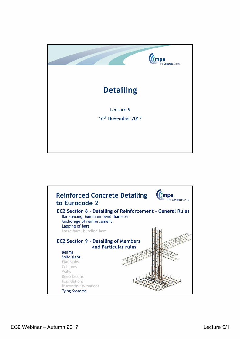
Reinforced Concrete Detailing to Eurocode 2EC2 Section 8 - Detailing of Reinforcement - General Rules
Bar spacing, Minimum bend diameter
Anchorage of reinforcement
Lapping of bars
Large bars, bundled bars
EC2 Section 9 - Detailing of Membersand Particular rules
Beams
Solid slabs
Flat slabs
Columns
Walls
Deep beams
Foundations
Discontinuity regions
Tying Systems
EC2 Webinar – Autumn 2017 Lecture 9/2
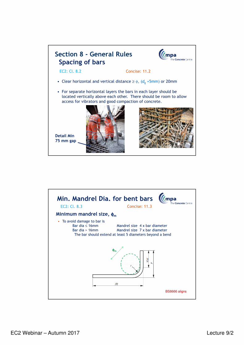
• Clear horizontal and vertical distance ≥ φ, (dg +5mm) or 20mm
• For separate horizontal layers the bars in each layer should be
located vertically above each other. There should be room to allow
access for vibrators and good compaction of concrete.
Section 8 - General RulesSpacing of bars
EC2: Cl. 8.2 Concise: 11.2
Detail Min75 mm gap
• To avoid damage to bar is
Bar dia ≤ 16mm Mandrel size 4 x bar diameter
Bar dia > 16mm Mandrel size 7 x bar diameter
The bar should extend at least 5 diameters beyond a bend
Minimum mandrel size, φφφφm
Min. Mandrel Dia. for bent barsEC2: Cl. 8.3 Concise: 11.3
φφφφm
BS8666 aligns
EC2 Webinar – Autumn 2017 Lecture 9/3
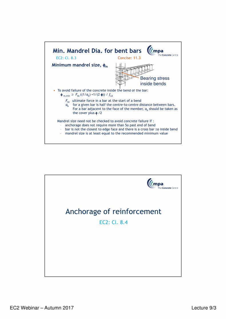
Minimum mandrel size, φφφφm
• To avoid failure of the concrete inside the bend of the bar:
φφφφ m,min ≥ Fbt ((1/ab) +1/(2 φφφφ)) / fcd
Fbt ultimate force in a bar at the start of a bend
ab for a given bar is half the centre-to-centre distance between bars.
For a bar adjacent to the face of the member, ab should be taken as
the cover plus φφφφ /2
Mandrel size need not be checked to avoid concrete failure if :
– anchorage does not require more than 5φ past end of bend
– bar is not the closest to edge face and there is a cross bar ≥φ inside bend
– mandrel size is at least equal to the recommended minimum value
Min. Mandrel Dia. for bent barsEC2: Cl. 8.3 Concise: 11.3
Bearing stress
inside bends
Anchorage of reinforcement
EC2: Cl. 8.4

EC2 Webinar – Autumn 2017 Lecture 9/4
The design value of the ultimate bond stress,
fbd = 2.25 η1η2fctd
where
fctd should be limited to C60/75
η1 = 1 for ‘good’ and 0.7 for ‘poor’ bond conditions
η2 = 1 for φ ≤ 32, otherwise (132- φ)/100
Ultimate bond stress
EC2: Cl. 8.4.2 Concise: 11.5
Ultimate bond stress
EC2: Cl. 8.4.2, Fig 8.2 Concise: 11.5
Good and ‘bad’ bond conditions
Top is ‘poor’
Bond condition
unhatched zone – ‘good’ bond conditions
hatched zone - ‘poor’ bond conditions
EC2 Webinar – Autumn 2017 Lecture 9/5
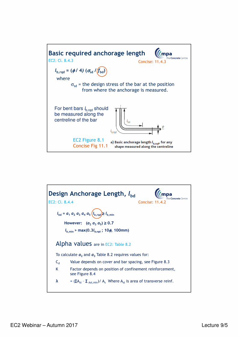
lb,rqd = (φ φ φ φ / 4) (σσσσsd / fbd)
where
σsd = the design stress of the bar at the position
from where the anchorage is measured.
Basic required anchorage lengthEC2: Cl. 8.4.3 Concise: 11.4.3
For bent bars lb,rqd should
be measured along the
centreline of the bar
EC2 Figure 8.1
Concise Fig 11.1
lbd = α1 α2 α3 α4 α5 lb,rqd ≥≥≥≥ lb,min
However: (α2 α3 α5) ≥≥≥≥ 0.7
lb,min> max(0.3lb,rqd ; 10φφφφ, 100mm)
Design Anchorage Length, lbdEC2: Cl. 8.4.4 Concise: 11.4.2
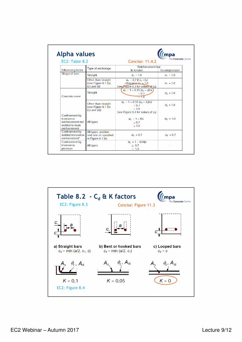
Alpha values are in EC2: Table 8.2
To calculate α2 and α3 Table 8.2 requires values for:
Cd Value depends on cover and bar spacing, see Figure 8.3
K Factor depends on position of confinement reinforcement,
see Figure 8.4
λ = (∑Ast – ∑ Ast,min)/ As Where Ast is area of transverse reinf.
EC2 Webinar – Autumn 2017 Lecture 9/6
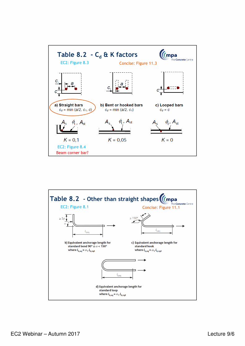
Table 8.2 - Cd & K factorsConcise: Figure 11.3EC2: Figure 8.3
EC2: Figure 8.4
Beam corner bar?
Table 8.2 - Other than straight shapesConcise: Figure 11.1EC2: Figure 8.1
EC2 Webinar – Autumn 2017 Lecture 9/7
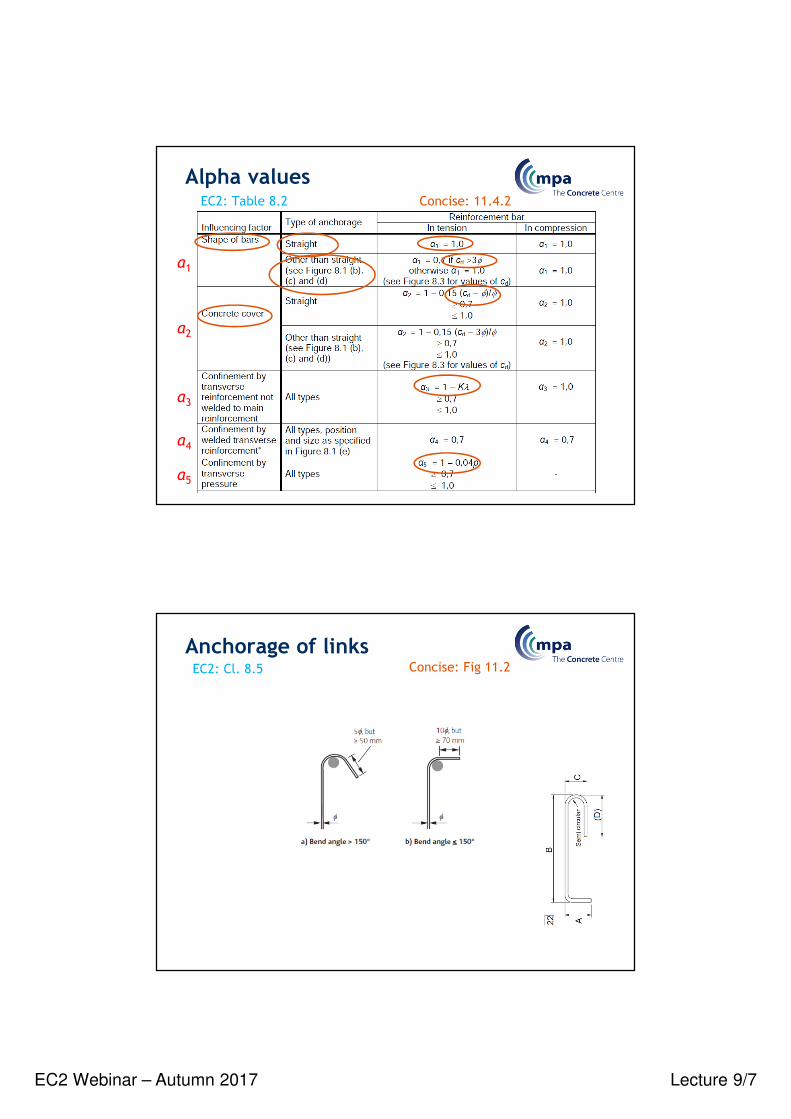
Alpha valuesEC2: Table 8.2 Concise: 11.4.2
α1
α2
α3
α4
α5
Anchorage of links Concise: Fig 11.2EC2: Cl. 8.5
EC2 Webinar – Autumn 2017 Lecture 9/8
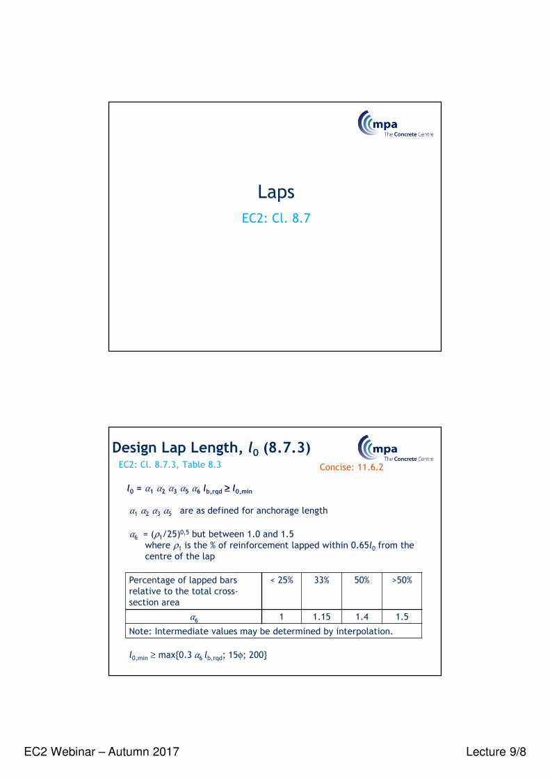
Laps
EC2: Cl. 8.7
l0 = α1 α2 α3 α5 α6 lb,rqd ≥≥≥≥ l0,min
α6 = (ρ1/25)0,5 but between 1.0 and 1.5
where ρ1 is the % of reinforcement lapped within 0.65l0 from the
centre of the lap
Percentage of lapped bars
relative to the total cross-
section area
< 25% 33% 50% >50%
α6 1 1.15 1.4 1.5
Note: Intermediate values may be determined by interpolation.
α1 α2 α3 α5 are as defined for anchorage length
l0,min ≥ max{0.3 α6 lb,rqd; 15φ; 200}
Design Lap Length, l0 (8.7.3)EC2: Cl. 8.7.3, Table 8.3 Concise: 11.6.2
EC2 Webinar – Autumn 2017 Lecture 9/9
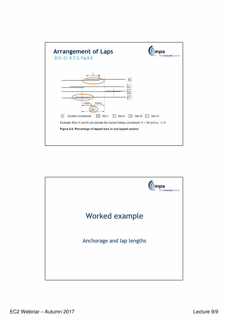
Arrangement of LapsEC2: Cl. 8.7.3, Fig 8.8
Worked example
Anchorage and lap lengths
EC2 Webinar – Autumn 2017 Lecture 9/10
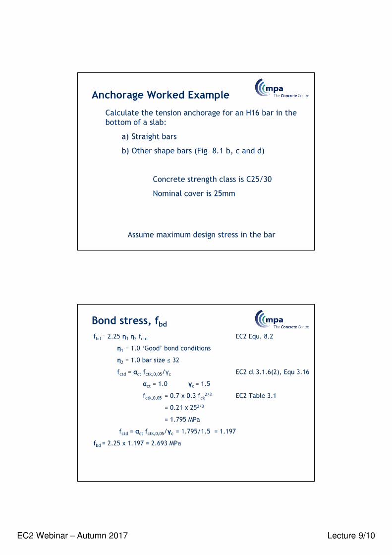
Anchorage Worked Example
Calculate the tension anchorage for an H16 bar in the
bottom of a slab:
a) Straight bars
b) Other shape bars (Fig 8.1 b, c and d)
Concrete strength class is C25/30
Nominal cover is 25mm
Assume maximum design stress in the bar
Bond stress, fbdfbd = 2.25 η1 η2 fctd EC2 Equ. 8.2
η1 = 1.0 ‘Good’ bond conditions
η2 = 1.0 bar size ≤ 32
fctd = αct fctk,0,05/γc EC2 cl 3.1.6(2), Equ 3.16
αct = 1.0 γc = 1.5
fctk,0,05 = 0.7 x 0.3 fck2/3 EC2 Table 3.1
= 0.21 x 252/3
= 1.795 MPa
fctd = αct fctk,0,05/γc = 1.795/1.5 = 1.197
fbd = 2.25 x 1.197 = 2.693 MPa
EC2 Webinar – Autumn 2017 Lecture 9/11
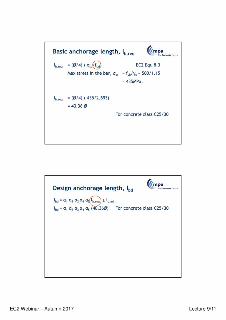
Basic anchorage length, lb,req
lb.req = (Ø/4) ( σsd/fbd) EC2 Equ 8.3
Max stress in the bar, σsd = fyk/γs = 500/1.15
= 435MPa.
lb.req = (Ø/4) ( 435/2.693)
= 40.36 Ø
For concrete class C25/30
Design anchorage length, lbd
lbd = α1 α2 α3 α4 α5 lb.req ≥ lb,min
lbd = α1 α2 α3 α4 α5 (40.36Ø) For concrete class C25/30
EC2 Webinar – Autumn 2017 Lecture 9/12
Alpha valuesEC2: Table 8.2 Concise: 11.4.2
Table 8.2 - Cd & K factorsConcise: Figure 11.3EC2: Figure 8.3
EC2: Figure 8.4

EC2 Webinar – Autumn 2017 Lecture 9/13
Design anchorage length, lbdlbd = α1 α2 α3 α4 α5 lb.req ≥ lb,min
lbd = α1 α2 α3 α4 α5 (40.36Ø) For concrete class C25/30
a) Tension anchorage – straight bar
α1 = 1.0
α3 = 1.0 conservative value with K= 0
α4 = 1.0 N/A
α5 = 1.0 conservative value
α2 = 1.0 – 0.15 (Cd – Ø)/Ø
α2 = 1.0 – 0.15 (25 – 16)/16 = 0.916
lbd = 0.916 x 40.36Ø = 36.97Ø = 592mm
Design anchorage length, lbd
lbd = α1 α2 α3 α4 α5 lb.req ≥ lb,min
lbd = α1 α2 α3 α4 α5 (40.36Ø) For concrete class C25/30
b) Tension anchorage – Other shape bars
α1 = 1.0 Cd = 25 is ≤ 3 Ø = 3 x 16 = 48
α3 = 1.0 conservative value with K= 0
α4 = 1.0 N/A
α5 = 1.0 conservative value
α2 = 1.0 – 0.15 (Cd – 3Ø)/Ø ≤ 1.0
α2 = 1.0 – 0.15 (25 – 48)/16 = 1.25 ≤ 1.0
lbd = 1.0 x 40.36Ø = 40.36Ø = 646mm

EC2 Webinar – Autumn 2017 Lecture 9/14
Worked example - summary
H16 Bars – Concrete class C25/30 – 25 Nominal cover
Tension anchorage – straight bar lbd = 36.97Ø = 592mm
Tension anchorage – Other shape bars lbd = 40.36Ø = 646mm
lbd is measured along the centreline of the bar
Compression anchorage (α1 = α2 = α3 = α4 = α5 = 1.0)
lbd = 40.36Ø = 646mm
Anchorage for ‘Poor’ bond conditions, lbd = ‘Good value’ /0.7
Lap length, l0 = anchorage length x α6
Anchorage & lap lengthsHow to design concrete structures using Eurocode 2
Column lap length for 100% laps & grade C40/50 = 0.73 x 61Ф = 44.5 Ф
EC2 Webinar – Autumn 2017 Lecture 9/15
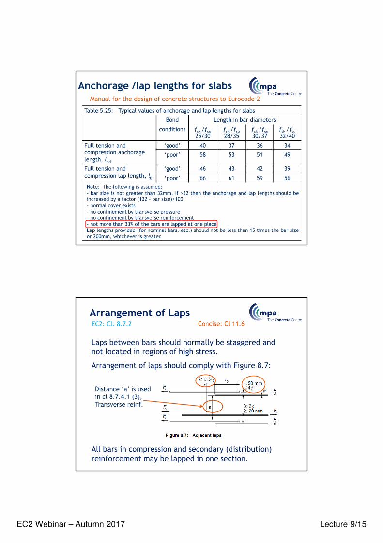
Table 5.25: Typical values of anchorage and lap lengths for slabs
Bond Length in bar diameters
conditions fck /fcu
25/30
fck /fcu28/35
fck /fcu
30/37
fck /fcu32/40
Full tension and
compression anchorage
length, lbd
‘good’ 40 37 36 34
‘poor’ 58 53 51 49
Full tension and
compression lap length, l0
‘good’ 46 43 42 39
‘poor’ 66 61 59 56
Note: The following is assumed:
- bar size is not greater than 32mm. If >32 then the anchorage and lap lengths should be
increased by a factor (132 - bar size)/100
- normal cover exists
- no confinement by transverse pressure
- no confinement by transverse reinforcement
- not more than 33% of the bars are lapped at one place
Lap lengths provided (for nominal bars, etc.) should not be less than 15 times the bar size
or 200mm, whichever is greater.
Anchorage /lap lengths for slabsManual for the design of concrete structures to Eurocode 2
Laps between bars should normally be staggered and
not located in regions of high stress.
Arrangement of laps should comply with Figure 8.7:
All bars in compression and secondary (distribution)
reinforcement may be lapped in one section.
Arrangement of LapsEC2: Cl. 8.7.2 Concise: Cl 11.6
Distance ‘a’ is used
in cl 8.7.4.1 (3),
Transverse reinf.

EC2 Webinar – Autumn 2017 Lecture 9/16
F
There is transverse tension
Strut-and-tie modelsSTM models help us understand:
• The anchorage of bars
• Any Transverse reinforcement provided for other reasons will be
sufficient if the lapped bar Ø < 20mm or laps< 25%
• If the lapped bar Ø ≥ 20mm the transverse reinforcement should have a
total area, ΣAst ≥ 1,0As of one spliced bar. It should be placed perpendicular
to the direction of the lapped reinforcement. Also it should be positioned at
the outer sections of the lap as shown.
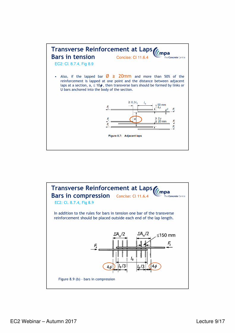
Transverse Reinforcement at LapsBars in tension
EC2: Cl. 8.7.4, Fig 8.9
Concise: Cl 11.6.4
• Transverse reinforcement is required in the lap zone to resist transverse
tension forces.
l /30
ΣA /2st
ΣA /2st
l /30
FsFs
≤150 mm
l0Figure 8.9 (a) -
bars in tension
EC2 Webinar – Autumn 2017 Lecture 9/17
Transverse Reinforcement at LapsBars in tension
EC2: Cl. 8.7.4, Fig 8.9
Concise: Cl 11.6.4
• Also, if the lapped bar Ø ≥ 20mm and more than 50% of the
reinforcement is lapped at one point and the distance between adjacent
laps at a section, a, ≤ 10φφφφ , then transverse bars should be formed by links or
U bars anchored into the body of the section.
Transverse Reinforcement at LapsBars in compression
EC2: Cl. 8.7.4, Fig 8.9
Concise: Cl 11.6.4
In addition to the rules for bars in tension one bar of the transverse
reinforcement should be placed outside each end of the lap length.
Figure 8.9 (b) – bars in compression
EC2 Webinar – Autumn 2017 Lecture 9/18
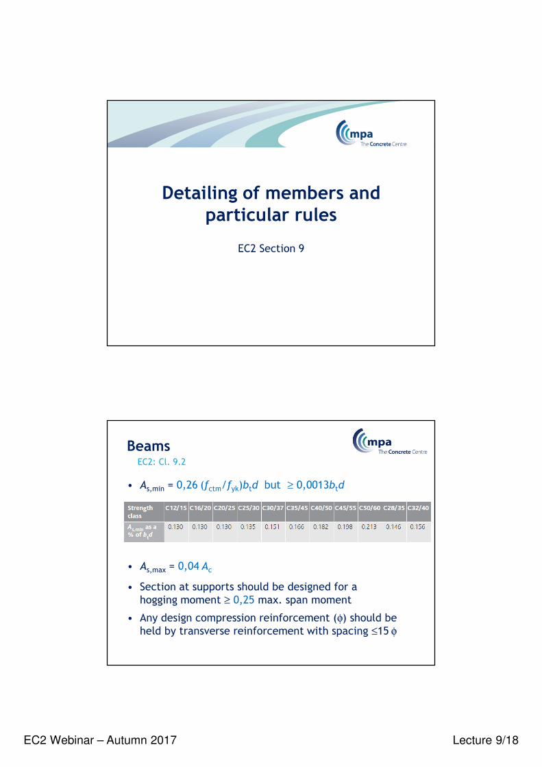
EC2 Section 9
Detailing of members and particular rules
• As,min = 0,26 (fctm/fyk)btd but ≥ 0,0013btd
• As,max = 0,04 Ac
• Section at supports should be designed for a
hogging moment ≥ 0,25 max. span moment
• Any design compression reinforcement (φ) should be
held by transverse reinforcement with spacing ≤15 φ
Beams EC2: Cl. 9.2
EC2 Webinar – Autumn 2017 Lecture 9/19
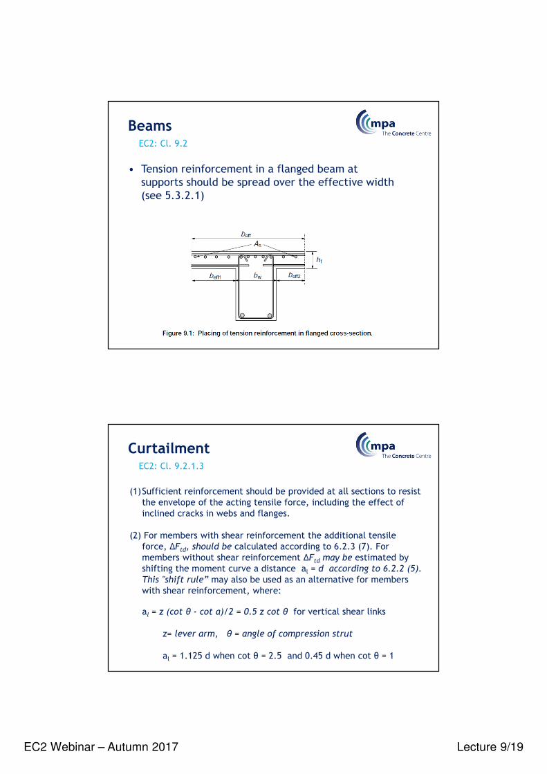
• Tension reinforcement in a flanged beam at
supports should be spread over the effective width
(see 5.3.2.1)
Beams EC2: Cl. 9.2
(1)Sufficient reinforcement should be provided at all sections to resist
the envelope of the acting tensile force, including the effect of
inclined cracks in webs and flanges.
(2) For members with shear reinforcement the additional tensile
force, TFtd, should be calculated according to 6.2.3 (7). For
members without shear reinforcement TFtd may be estimated by
shifting the moment curve a distance al = d according to 6.2.2 (5).
This "shift rule” may also be used as an alternative for members
with shear reinforcement, where:
al = z (cot θ - cot α)/2 = 0.5 z cot θ for vertical shear links
z= lever arm, θ = angle of compression strut
al = 1.125 d when cot θ = 2.5 and 0.45 d when cot θ = 1
Curtailment EC2: Cl. 9.2.1.3
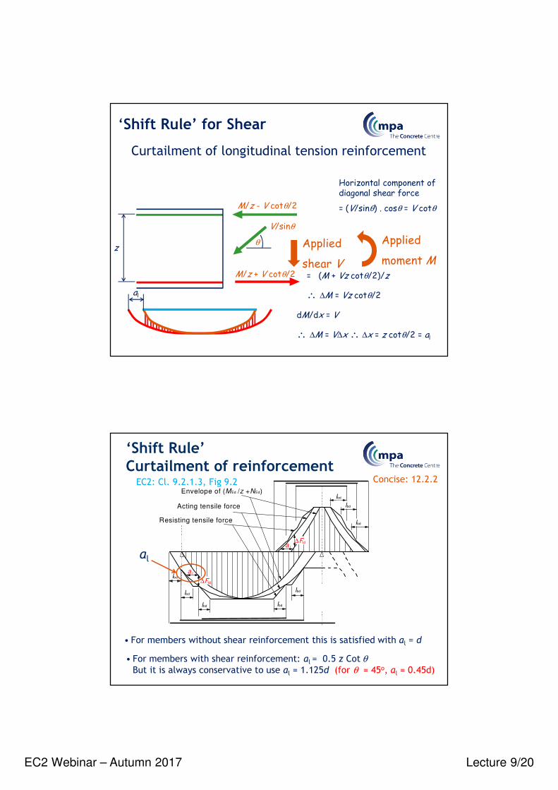
EC2 Webinar – Autumn 2017 Lecture 9/20
Horizontal component of diagonal shear force
= (V/sinθ) . cosθ = V cotθ
Applied
shear V
Applied
moment MM/z + V cotθ/2 = (M + Vz cotθ/2)/z
∴ ∆M = Vz cotθ/2
dM/dx = V
∴ ∆M = V∆x ∴ ∆x = z cotθ/2 = al
z
V/sinθ
θ
M/z - V cotθ/2
al
Curtailment of longitudinal tension reinforcement
‘Shift Rule’ for Shear
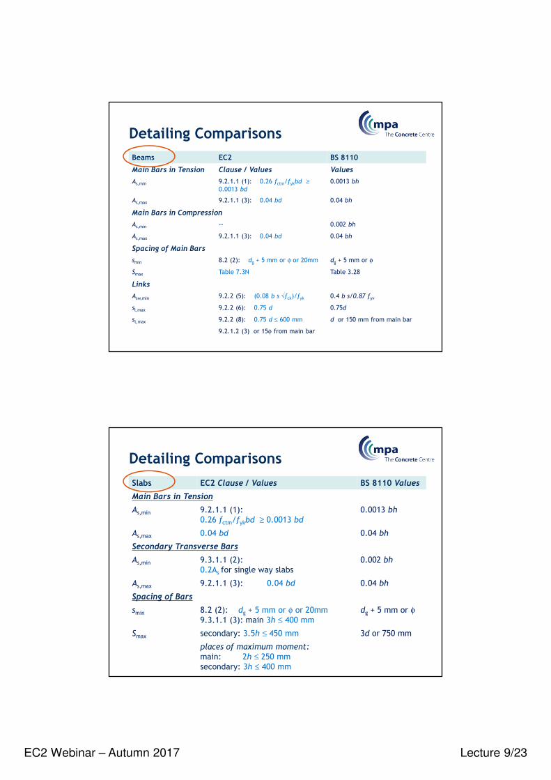
• For members without shear reinforcement this is satisfied with al = d
a l
∆Ftd
a l
Envelope of (MEd /z +NEd)
Acting tensile force
Resisting tensile force
lbd
lbd
lbd
lbd
lbd lbd
lbd
lbd
∆Ftd
‘Shift Rule’Curtailment of reinforcement
EC2: Cl. 9.2.1.3, Fig 9.2 Concise: 12.2.2
• For members with shear reinforcement: al = 0.5 z Cot θBut it is always conservative to use al = 1.125d (for θ = 45o, al = 0.45d)
al

EC2 Webinar – Autumn 2017 Lecture 9/21
• lbd is required from the line of contact of the support.
Simple support (indirect) Simple support (direct)
• As bottom steel at support ≥ 0.25 As provided in the span
• Transverse pressure may only be taken into account with
a ‘direct’ support. α5 anchorage coefficient
Anchorage of Bottom Reinforcement at End Supports
EC2: Cl. 9.2.1.4
Simplified Detailing Rules for Beams
How to….EC2
Detailing section
Concise: Cl 12.2.4

EC2 Webinar – Autumn 2017 Lecture 9/22
≤ h /31
≤ h /21
B
A
≤ h /32
≤ h /22
supporting beam with height h1
supported beam with height h2 (h1 ≥ h2)
• The supporting reinforcement is in
addition to that required for other
reasons
A
B
• The supporting links may be placed in a zone beyond
the intersection of beams
Supporting Reinforcement at ‘Indirect’ Supports
Plan view
EC2: Cl. 9.2.5
Concise: Cl 12.2.8
• Curtailment – as beams except for the “Shift” rule al = d
may be used
• Flexural Reinforcement – min and max areas as beam
• Secondary transverse steel not less than 20% main
reinforcement
• Reinforcement at Free Edges
Solid slabsEC2: Cl. 9.3
EC2 Webinar – Autumn 2017 Lecture 9/23
Detailing Comparisons
Beams EC2 BS 8110
Main Bars in Tension Clause / Values Values
As,min 9.2.1.1 (1): 0.26 fctm/fykbd ≥0.0013 bd
0.0013 bh
As,max 9.2.1.1 (3): 0.04 bd 0.04 bh
Main Bars in Compression
As,min -- 0.002 bh
As,max 9.2.1.1 (3): 0.04 bd 0.04 bh
Spacing of Main Bars
smin 8.2 (2): dg + 5 mm or φ or 20mm dg + 5 mm or φ
Smax Table 7.3N Table 3.28
Links
Asw,min 9.2.2 (5): (0.08 b s √fck)/fyk 0.4 b s/0.87 fyv
sl,max 9.2.2 (6): 0.75 d 0.75d
st,max 9.2.2 (8): 0.75 d ≤ 600 mm
9.2.1.2 (3) or 15φ from main bar
d or 150 mm from main bar
Detailing Comparisons
Slabs EC2 Clause / Values BS 8110 Values
Main Bars in Tension
As,min 9.2.1.1 (1):
0.26 fctm/fykbd ≥ 0.0013 bd
0.0013 bh
As,max 0.04 bd 0.04 bh
Secondary Transverse Bars
As,min 9.3.1.1 (2):
0.2As for single way slabs
0.002 bh
As,max 9.2.1.1 (3): 0.04 bd 0.04 bh
Spacing of Bars
smin 8.2 (2): dg + 5 mm or φ or 20mm
9.3.1.1 (3): main 3h ≤ 400 mm
dg + 5 mm or φ
Smax secondary: 3.5h ≤ 450 mm 3d or 750 mm
places of maximum moment:
main: 2h ≤ 250 mm
secondary: 3h ≤ 400 mm
EC2 Webinar – Autumn 2017 Lecture 9/24
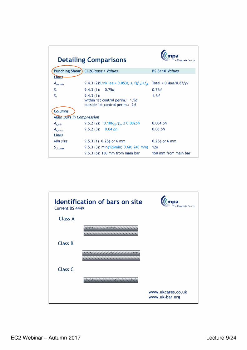
Detailing Comparisons
Punching Shear EC2Clause / Values BS 8110 Values
Links
Asw,min 9.4.3 (2):Link leg = 0.053sr st √(fck)/fyk Total = 0.4ud/0.87fyv
Sr 9.4.3 (1): 0.75d 0.75d
St 9.4.3 (1):
within 1st control perim.: 1.5d
outside 1st control perim.: 2d
1.5d
Columns
Main Bars in Compression
As,min 9.5.2 (2): 0.10NEd/fyk ≤ 0.002bh 0.004 bh
As,max 9.5.2 (3): 0.04 bh 0.06 bh
Links
Min size 9.5.3 (1) 0.25φ or 6 mm 0.25φ or 6 mm
Scl,tmax 9.5.3 (3): min(12φmin; 0.6b; 240 mm) 12φ
9.5.3 (6): 150 mm from main bar 150 mm from main bar
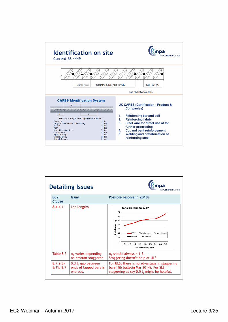
Class A
Class B
Class C
www.ukcares.co.uk www.uk-bar.org
Identification of bars on siteCurrent BS 4449
EC2 Webinar – Autumn 2017 Lecture 9/25
UK CARES (Certification - Product & Companies)
1. Reinforcing bar and coil 2. Reinforcing fabric 3. Steel wire for direct use of for
further processing 4. Cut and bent reinforcement 5. Welding and prefabrication of
reinforcing steel
Identification on siteCurrent BS 4449
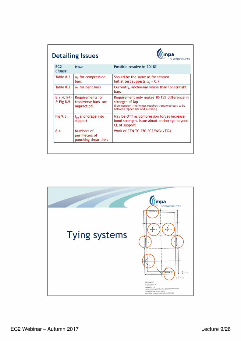
Detailing Issues
EC2 Clause
Issue Possible resolve in 2018?
8.4.4.1 Lap lengths
Table 8.3 α6 varies depending
on amount staggered
α6 should always = 1.5.
Staggering doesn’t help at ULS
8.7.2(3)
& Fig 8.7
0.3 lo gap between
ends of lapped bars is
onerous.
For ULS, there is no advantage in staggering
bars( fib bulletin Mar 2014). For SLS
staggering at say 0.5 lo might be helpful.
EC2 Webinar – Autumn 2017 Lecture 9/26
Detailing Issues
EC2 Clause
Issue Possible resolve in 2018?
Table 8.2 α2 for compression
bars
Should be the same as for tension.
Initial test suggests α2 = 0.7
Table 8.2 α2 for bent bars Currently, anchorage worse than for straight
bars
8.7.4.1(4)
& Fig 8.9
Requirements for
transverse bars are
impractical
Requirement only makes 10-15% difference in
strength of lap (Corrigendum 1 no longer requires transverse bars to be
between lapped bar and surface.)
Fig 9.3 lbd anchorage into
support
May be OTT as compression forces increase
bond strength. Issue about anchorage beyond
CL of support
6.4 Numbers of
perimeters of
punching shear links
Work of CEN TC 250.SC2/WG1/TG4
Tying systems

EC2 Webinar – Autumn 2017 Lecture 9/27
• Peripheral ties (9.10.2.2) & NA:
Ftie,per = (20 + 4n0) ≤ 60kN
where n0 is the number of storeys
• Internal ties (including transverse ties) (9.10.2.3) & NA :
Ftie,int = ((gk + qk) / 7.5 )(lr/5)Ft ≥ Ft kN/m
where (gk + qk) is the sum of the average permanent and variable floor loads (kN/m2), lr is the greater of the distances (m) between the centres of the columns, frames or walls supporting any two adjacent floor spans in the direction of the tie under consideration and Ft = (20 + 4n0) ≤ 60kN.Maximum spacing of internal ties = 1.5 lr
• Horizontal ties to columns or walls (9.10.2.4) & NA :
Ftie,fac = Ftie,col ≥ (2 Ft ≤ (ls /2.5)Ft) and ≥ 3% of NEd
NEd = the total design ultimate vertical load carried by the column or wall at that level. Tying
of external walls is only required if the peripheral tie is not located within the wall. Ftie,fac in kN per metre run of wall, Ftie,col in kN per column and ls is the floor to ceiling height in m.
Tying systems
Internal Ties: EC2 specifies a
20kN/m requirement which is
significantly less than BS8110.
UK NA requirements similar to BS 8110
Tying Systems

EC2 Webinar – Autumn 2017 Lecture 9/28
• Vertical ties (9.10.2.5):In panel buildings of 5 storeys or more, ties should be provided in
columns and/or walls to limit damage of collapse of a floor.
Normally continuous vertical ties should be provided from the lowest
to the highest level.
Where a column or wall is supported at the bottom by a beam or slab
accidental loss of this element should be considered.
• Continuity and anchorage ties (9.10.3):Ties in two horizontal directions shall be effectively continuous and
anchored at the perimeter of the structure.
Ties may be provided wholly in the insitu concrete topping or at
connections of precast members.
Tying Systems
Exercise
Lecture 9
Lap length for column longitudinal bars
EC2 Webinar – Autumn 2017 Lecture 9/29
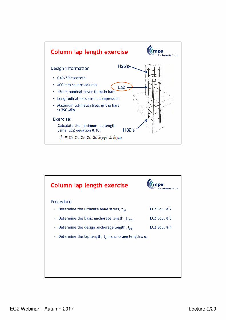
Column lap length exercise
H25’s
H32’s
Lap
Design information
• C40/50 concrete
• 400 mm square column
• 45mm nominal cover to main bars
• Longitudinal bars are in compression
• Maximum ultimate stress in the bars
is 390 MPa
Exercise:
Calculate the minimum lap length
using EC2 equation 8.10:
Column lap length exercise
Procedure
• Determine the ultimate bond stress, fbd EC2 Equ. 8.2
• Determine the basic anchorage length, lb,req EC2 Equ. 8.3
• Determine the design anchorage length, lbd EC2 Equ. 8.4
• Determine the lap length, l0 = anchorage length x α6