Lecture 9 Ch. 7 Determination of S3 from mini-fracs and ...
26
Lecture 9 Ch. 7 Determination of S 3 from mini-fracs and extended leak-off tests and determining S Hmax from vertical wells (4 May 2020) Ki-Bok Min, PhD Professor Department of Energy Resources Engineering Seoul National University Reservoir Geomechanics, Fall, 2020
Transcript of Lecture 9 Ch. 7 Determination of S3 from mini-fracs and ...

Lecture 9
Ch. 7 Determination of S3 from mini-fracsand extended leak-off tests and determining
SHmax from vertical wells(4 May 2020)
Ki-Bok Min, PhD
Professor
Department of Energy Resources Engineering
Seoul National University
Reservoir Geomechanics, Fall, 2020

Disclaimer
• Materials in this slides cannot be used without the written consent from the instructor

IntroductionImportance
• Minimum principal stress, S3
– Shmin: normal and strike slip faulting environment
– Sv: reverse faulting environment
• Importance of measuring SHmax
– Wellbore imaging
– Careful when determining from hydraulic fracturing
• Importance
– Wellbore stability:
Optimal mud weights
Well trajectories
Casing set points
– Shear failure in pre-existing fracture/fault

IntroductionTerminology
• Leak-off Test (LOT)* - open hole
– Performed during the drilling of the well after setting a casing shoe and typically performed with drilling mud.
• Extended leak-off test* - open hole
– Similar to a leakoff test, but with multiple cycles of shut-in and injection. Carried out beyond leak-off point (LOP)
• Microfrac** - cased hole with perforation or open hole
– Performed with a particularly small volume of fluid. Wireline tools can be used to perform microfrac tests, and different service companies have their own names for the tools used for these tests. With the purpose of measuring in situ stress
– 2-100 gal (10-500l), 1-10 gal/min***
• Mini-frac** - cased hole with perforation (or open hole)
– A small fracturing treatment performed before the main hydraulic fracturing treatment to acquire critical job design and execution data and confirm the predicted response of the treatment interval.
– 10-100 bbl (1,500-15,000l), 5-10 bbl/min****McClure, 2017, resfrac.com, **Schlumberger oilfield dictionary, ***De Bree, P. and J. V. Walters (1989). "Micro/minifrac test procedures and interpretation for in situ stress
determination." Int J Rock Mech Min Sci & Geomech Abstr 26(6): 515-521., , ****Lin et al., 2008, Estimation of Minimum Principal Stress from an Extended Leak-off Test
Onboard the Chikyu Drilling Vessel and Suggestions for Future Test Procedures, Scientific Drilling, No. 6, July 2008, 43-47, *****Thiercelin MC,Rogiers JC, 2000, Hydraulic
Stimulation. Ch.3. Formation Characterization: Rock Mechanics (Eds) Economides MJ & Nolte KG, 3rd ed, Wiley
Leak-off Test****
Micro hydraulic fracturing*****

IntroductionMethod of determining S3
• Magnitude of S3
– Micro-frac
– Mini-frac
– Leak-off test
– Extended leak-off teste
– Mud loss (lost circulation)
– Wellbore ballooning during logging-while drilling (LWD)
Indicate that wellbore pressure is very close to S3
Hydraulic fracturing to determine S3
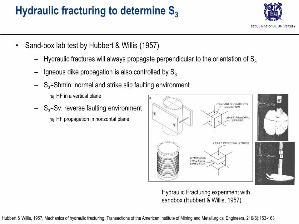
• Sand-box lab test by Hubbert & Willis (1957)
– Hydraulic fractures will always propagate perpendicular to the orientation of S3
– Igneous dike propagation is also controlled by S3
– S3=Shmin: normal and strike slip faulting environment
HF in a vertical plane
– S3=Sv: reverse faulting environment
HF propagation in horizontal plane
Hydraulic Fracturing experiment with
sandbox (Hubbert & Willis, 1957)
Hubbert & Willis, 1957, Mechanics of hydraulic fracturing, Transactions of the American Institute of Mining and Metallurgical Engineers, 210(6):153-163

Hydraulic fracturing to determine S3Typical pressure curve during mini-frac or extended leak-off test
• LT (or FIT): when LOP is not reached
• LOP: Leak off point
– HF must have formed
– Why?
• Clear LOP ~ S3
• LOP can be >S3, due to
– Tortuosity due to perforation
– Injection rate is too high
– High viscosity
• Quality of LOT
– LOP clear?
– Stable FPP achieved?
– Exceptionally low LOP can be found
due to problematic cementing job
Zoback MD, 2007, Reservoir Geomechanics, Cambridge University Press

Hydraulic fracturing to determine S3Typical pressure curve during mini-frac or extended leak-off test
• FBP: Formation breakdown pressure
• FPP: Fracture propagation pressure
– FPP~ S3 FPP~LOP
• ISIP: instantaneous shut-in pressure
– Change in linearity at pressure decay with time curve
– Low flow rate test with low viscosity: LOP~FPP~ISIP
• FCP: fracture closure pressure
– Change in linearity at pressure decay with square root of time curve
– With viscous fluid or suspended proppant
Zoback MD, 2007, Reservoir Geomechanics, Cambridge University Press

Hydraulic fracturing to determine S3
• Wellbore pressure to initiate tensile fracture (Pini) in open hole
• Pini>S3
– Pressure drops after fracture initiation
• Pini<S3
– Pressure climbs to S3 after tensile failure

Hydraulic fracturing to determine S3Mini-frac test (Timor Sea)
• Flow rate: 0.5 bbl/min
– Total injection?
• 1st cycle
– FPP: not clear
– ISIP
• 2nd cycle
– FPP: clear
– ISIP
• Small difference in ISIP and FCP
– Bottom hole pressure = surface pressure + hydrostatic pressure
– Small difference in ShminZoback MD, 2007, Reservoir Geomechanics, Cambridge University Press

Hydraulic fracturing to determine S3Pore pressure and S3 (Visund field, North Sea)
• Shmin by LOT is consistent
• When Shmin is very close to Sv
– 1) Shmin = S3
Vertical hydraulic fracture
– 2) Shmin = Sv
Horizontal hydraulic fracture propatation(Vertical hydraulic fracture at the wellbore may be formed but then it will rotate)
Careful determination of Sv is important
Zoback MD, 2007, Reservoir Geomechanics, Cambridge University Press

Hydraulic fracturing to determine S3S3 determination by step rate test (Alaska)
• Step rate test
– Pressurize wellbore in steps and measure the rate of pressure change
– When a fracture has formed, P increase during pressurization or decreased during stop
http://www.gwpc.org/sites/default/files/event-sessions/Wandke_Lewis.pdf
Zoback MD, 2007, Reservoir Geomechanics, Cambridge University Press

Hydraulic fracturing to determine S3S3 determination during LWD
• Pressure-while-drilling (PWD)
– During MWD (measurement-while-drilling) or LWD (logging-while-drilling)
– Provide info about S3
– During stop of drilling (installation of drill pipe)
– Static mud pressure
– Equivalent Circulating Density (ECD):
static + pressure difference effect (viscous resistance, suspended solid, p and T effect on mud, measurement error)
Pressure
difference effect
Zoback MD, 2007, Reservoir Geomechanics, Cambridge University Press
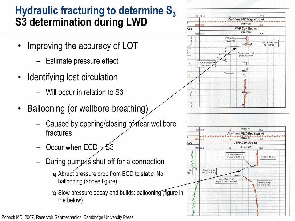
Hydraulic fracturing to determine S3S3 determination during LWD
• Improving the accuracy of LOT
– Estimate pressure effect
• Identifying lost circulation
– Will occur in relation to S3
• Ballooning (or wellbore breathing)
– Caused by opening/closing of near wellbore fractures
– Occur when ECD ~ S3
– During pump is shut off for a connection
Abrupt pressure drop from ECD to static: No ballooning (above figure)
Slow pressure decay and builds: ballooning (figure in the below)
Zoback MD, 2007, Reservoir Geomechanics, Cambridge University Press
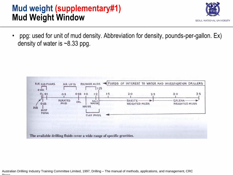
Mud weight (supplementary#1)Mud Weight Window
• ppg: used for unit of mud density. Abbreviation for density, pounds-per-gallon. Ex) density of water is ~8.33 ppg.
Australian Drilliing Industry Training Committee Limited, 1997, Drilling – The manual of methods, applications, and management, CRC
Press

LWD (Supplementary #2)Two types of logging method
• Wire-line logging:
– use equipment and sensors separate from drilling. Results are fed to the surface in real time
• LWD (logging while drilling):
– logs are made during drilling.
– Sensors are part of BHA (bottom hole assembly).
– Measurement are sent to back to the surface using pressure pulse (or stored in memory)
Wireline Log and LWD set-up (Rider & Kennedy, 2011)
Wire-line logging LWD
Rider M and Kennedy M, 2011, The geological interpretation of well logs, 3rd ed., Rider French
An example of LWD Bottom Hole Assembly (BHA): bit, MWD and LWD sensors

Can hydraulic fracturing determine SHmax?“Classical” hydraulic fracturing for stress measurement
• Shmax determination by ‘classical’ hydraulic fracturing technique for in situ stress measurement (in open hole)
Zoback MD, 2007, Reservoir Geomechanics, Cambridge University Press

Can hydraulic fracturing determine SHmax?“Classical” hydraulic fracturing for stress measurement
• Lecture note from “Rock Mechanics and Experiment (암석역학및실험)”
From Rock Mechanics class (2016)

Can hydraulic fracturing determine SHmax?“Classical” hydraulic fracturing for stress measurement
• Shmax can be determined by classical hydraulic fracturing in open hole. But it has limitation in deep borehole for petroleum/geothermal applications;
– Boreholes are cased – not open hole.
Shmin still valid
Stress concentration for fracture initiation is not valid
– Boreholes may not be circular and fracture may intersect – Kirsch solution may not be applicable
In Leak-off test, borehole imaging is not typically done.
– Very hard to detect fracture initiation fracture (and therefore pressure breakdown pressure)
Large borehole volume in deep petroleum/geothermal borehole hard to detect pressure change
- Classical HF: ~3 inch (a few hundreds m)
- Deep petroleum/geothermal well: ~8 1/2 inch open hole 7
inch cased hole (a few km)

Wellbore failure and SHmaxSHmax Magnitude from wellbore failure
• Borehole breakout
– Very good estimate of SHmax orientation.
– Can be used for SHmax magnitude?
Zoback MD, 2007, Reservoir Geomechanics, Cambridge University Press

Wellbore failure and SHmaxSHmax Magnitude from wellbore failure
• Example at KTB Scientific borehole (Germany)
– Borehole breakout and drilling induced tensile fractures were used for estimation of SHmax
– Greater variation is related to the temperature effect
+ lower limit
x upper limit
Δ lower limit
▲upper limit
Zoback MD, 2007, Reservoir Geomechanics, Cambridge University Press

Wellbore failure and SHmaxSHmax Magnitude from wellbore failure
• Example at Fenton Hill geothermal well (New Mexico, USA)
– Depth 3 km ~ 4.5 km
– UCS 124 MPa ~176 Mpa
– Normal faulting/strike-slip faulting
Zoback MD, 2007, Reservoir Geomechanics, Cambridge University Press

• Example at deep borehole in Australia
– UCS 138 ±14 MPa
– Borehole Breakout found: width 45 degrees
– Drilling induced tensile fracture was found.
Wellbore failure and SHmaxSHmax Magnitude from wellbore failure
Zoback MD, 2007, Reservoir Geomechanics, Cambridge University Press

• Example at deep borehole in Australia
– UCS 138 ±14 MPa
– Borehole Breakout found: width 45 degrees
– Drilling induced tensile fracture was found.
Wellbore failure and SHmaxSHmax Magnitude from wellbore failure
Zoback MD, 2007, Reservoir Geomechanics, Cambridge University Press

• Mud weight during drilling
– Encourage the drilling induced tensile fracture
– Should not influenced by operational drilling activities
• Example in Visund field (North Sea)
Drilling induced tensile fractures and the magnitudes of SHmax
Zoback MD, 2007, Reservoir Geomechanics, Cambridge University Press

Estimation of SHmax from breakout rotations
• Fault/fractures perturb the stress field
– Breakout orientations rotates
– Breakout may disappear locally
• KTB Scientific borehole
– Rotation of borehole breakout (5,399 m)
Δ modeling
+ observation
Zoback MD, 2007, Reservoir Geomechanics, Cambridge University Press