Lecture 8: Logical Shifts, Addressing modes in ARM ... 8: Logical Shifts, Addressing modes in ARM...
38
Lecture 8: Logical Shifts, Addressing modes in ARM Arithmetic Data Transfer Instructions CSE 30: Computer Organization and Systems Programming Diba Mirza Dept. of Computer Science and Engineering University of California, San Diego
Transcript of Lecture 8: Logical Shifts, Addressing modes in ARM ... 8: Logical Shifts, Addressing modes in ARM...

Lecture 8: Logical Shifts, Addressing modes in
ARM Arithmetic Data Transfer Instructions
CSE 30: Computer Organization and Systems Programming
Diba Mirza Dept. of Computer Science and Engineering
University of California, San Diego
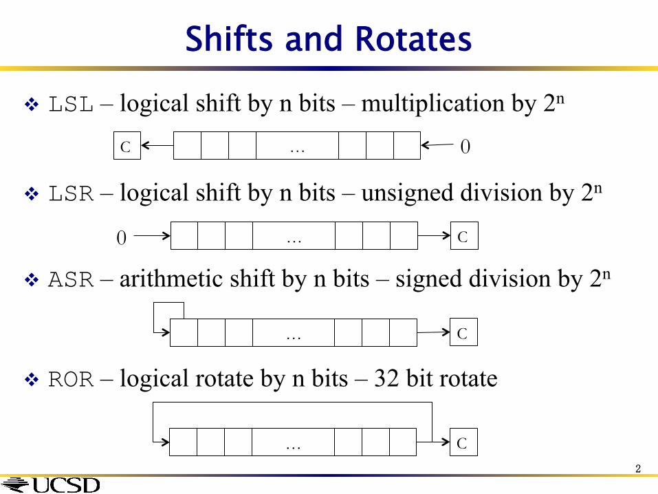
Shifts and Rotates v LSL – logical shift by n bits – multiplication by 2n
v LSR – logical shift by n bits – unsigned division by 2n
v ASR – arithmetic shift by n bits – signed division by 2n
v ROR – logical rotate by n bits – 32 bit rotate
… 0 C
… 0 C
… C
… C 2
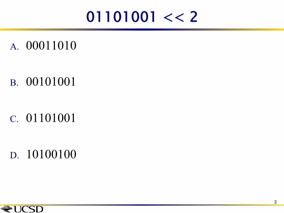
01101001 << 2
A. 00011010
B. 00101001
C. 01101001
D. 10100100
3

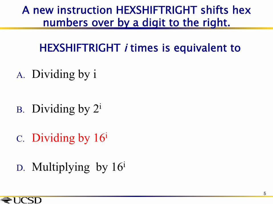
A new instruction HEXSHIFTRIGHT shifts hex numbers over by a digit to the right.
HEXSHIFTRIGHT i times is equivalent to
A. Dividing by i
B. Dividing by 2i
C. Dividing by 16i
D. Multiplying by 16i
4
A new instruction HEXSHIFTRIGHT shifts hex numbers over by a digit to the right.
HEXSHIFTRIGHT i times is equivalent to
A. Dividing by i
B. Dividing by 2i
C. Dividing by 16i
D. Multiplying by 16i
5
Ways of specifying operand 2
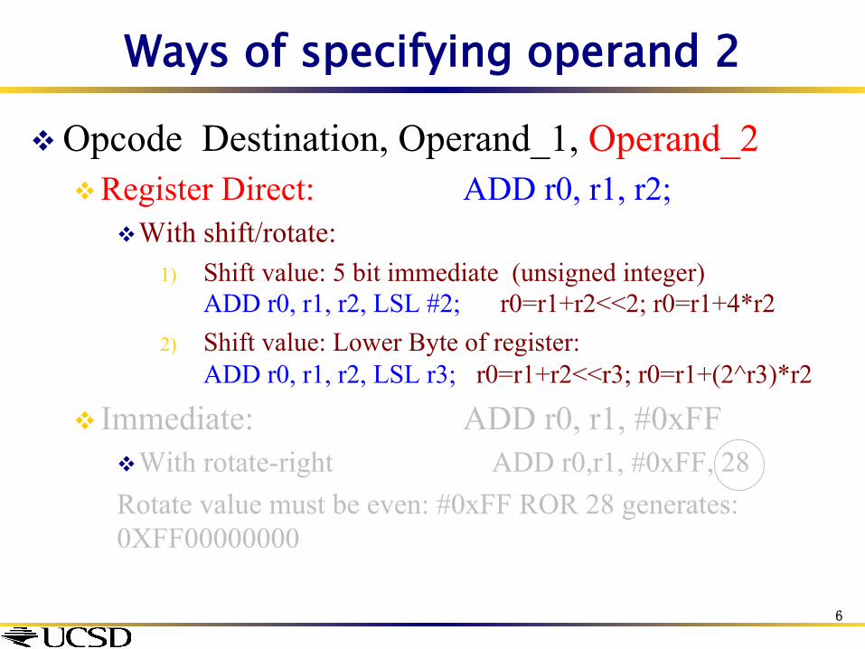
v Opcode Destination, Operand_1, Operand_2 v Register Direct: ADD r0, r1, r2;
v With shift/rotate: 1) Shift value: 5 bit immediate (unsigned integer)
ADD r0, r1, r2, LSL #2; r0=r1+r2<<2; r0=r1+4*r2 2) Shift value: Lower Byte of register:
ADD r0, r1, r2, LSL r3; r0=r1+r2<<r3; r0=r1+(2^r3)*r2
v Immediate: ADD r0, r1, #0xFF v With rotate-right ADD r0,r1, #0xFF, 28 Rotate value must be even: #0xFF ROR 28 generates: 0XFF00000000
6
Ways of specifying operand 2
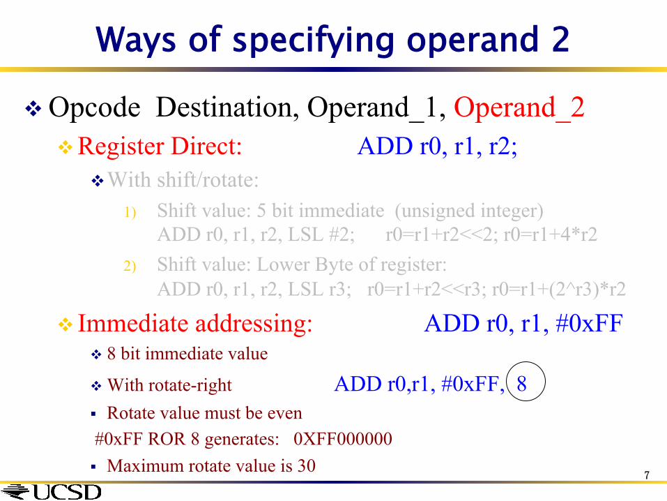
v Opcode Destination, Operand_1, Operand_2 v Register Direct: ADD r0, r1, r2;
v With shift/rotate: 1) Shift value: 5 bit immediate (unsigned integer)
ADD r0, r1, r2, LSL #2; r0=r1+r2<<2; r0=r1+4*r2 2) Shift value: Lower Byte of register:
ADD r0, r1, r2, LSL r3; r0=r1+r2<<r3; r0=r1+(2^r3)*r2
v Immediate addressing: ADD r0, r1, #0xFF v 8 bit immediate value
v With rotate-right ADD r0,r1, #0xFF, 8 § Rotate value must be even #0xFF ROR 8 generates: 0XFF000000 § Maximum rotate value is 30
7

v The data processing instruction format has 12 bits available for operand2
v 4 bit rotate value (0-15) is multiplied by two to
give range 0-30 in steps of 2
v Rule to remember is “8-bits rotated right by an even number of bit positions”
0 7 11 8
immed_8
Shifter ROR
rot
x2 0xFF000000 MOV r0, #0xFF,8
Reasons for constraints on Immediate Addressing
8
Immed_8=0xFF, rot =4
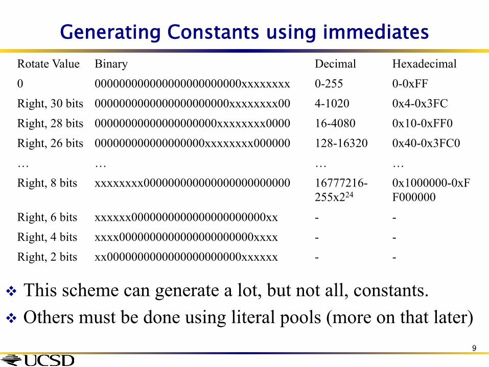
Generating Constants using immediates Rotate Value Binary Decimal Hexadecimal 0 000000000000000000000000xxxxxxxx 0-255 0-0xFF Right, 30 bits 0000000000000000000000xxxxxxxx00 4-1020 0x4-0x3FC Right, 28 bits 00000000000000000000xxxxxxxx0000 16-4080 0x10-0xFF0 Right, 26 bits 000000000000000000xxxxxxxx000000 128-16320 0x40-0x3FC0 … … … … Right, 8 bits xxxxxxxx000000000000000000000000 16777216-
255x224 0x1000000-0xFF000000
Right, 6 bits xxxxxx0000000000000000000000xx - - Right, 4 bits xxxx0000000000000000000000xxxx - - Right, 2 bits xx0000000000000000000000xxxxxx - -
v This scheme can generate a lot, but not all, constants. v Others must be done using literal pools (more on that later)
9

1. Register, optionally with shift operation v Shift value can either be:
v 5 bit unsigned integer v Specified in bottom byte of
another register. v Used for multiplication by constant
2. Immediate value v 8 bit number, with a range of 0-255.
v Rotated right through even number of positions
v Allows increased range of 32-bit constants to be loaded directly into registers
Result
Operand 1
Barrel Shifter
Operand 2
ALU
Implementation in h/w using a Barrel Shifter
10

Shifts and Rotates
v Shifting in Assembly Examples: MOV r4, r6, LSL #4 ; r4 = r6 << 4 MOV r4, r6, LSR #8 ; r4 = r6 >> 8
v Rotating in Assembly Examples: MOV r4, r6, ROR #12 ; r4 = r6 rotated right 12 bits
; r4 = r6 rotated left by 20 bits (32 -12)
Therefore no need for rotate left.
11

Variable Shifts and Rotates
v Also possible to shift by the value of a register v Examples:
MOV r4, r6, LSL r3 ; r4 = r6 << value specified in r3
MOV r4, r6, LSR #8 ; r4 = r6 >> 8
v Rotating in Assembly v Examples: MOV r4, r6, ROR r3
; r4 = r6 rotated right by value specified in r3
12
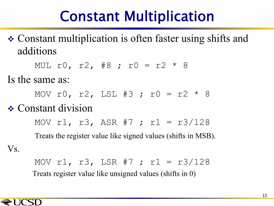
Constant Multiplication v Constant multiplication is often faster using shifts and
additions MUL r0, r2, #8 ; r0 = r2 * 8
Is the same as: MOV r0, r2, LSL #3 ; r0 = r2 * 8
v Constant division MOV r1, r3, ASR #7 ; r1 = r3/128
Treats the register value like signed values (shifts in MSB).
Vs. MOV r1, r3, LSR #7 ; r1 = r3/128
Treats register value like unsigned values (shifts in 0)
13
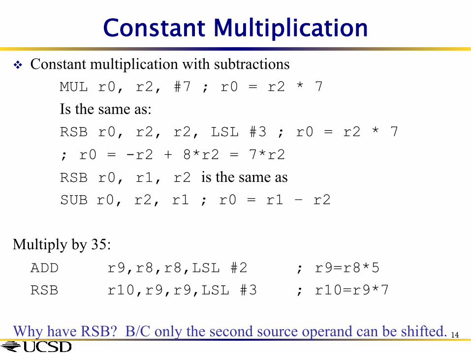
Constant Multiplication v Constant multiplication with subtractions
MUL r0, r2, #7 ; r0 = r2 * 7
Is the same as: RSB r0, r2, r2, LSL #3 ; r0 = r2 * 7
; r0 = -r2 + 8*r2 = 7*r2
RSB r0, r1, r2 is the same as SUB r0, r2, r1 ; r0 = r1 – r2
Multiply by 35:
ADD r9,r8,r8,LSL #2 ; r9=r8*5 RSB r10,r9,r9,LSL #3 ; r10=r9*7
Why have RSB? B/C only the second source operand can be shifted.
14
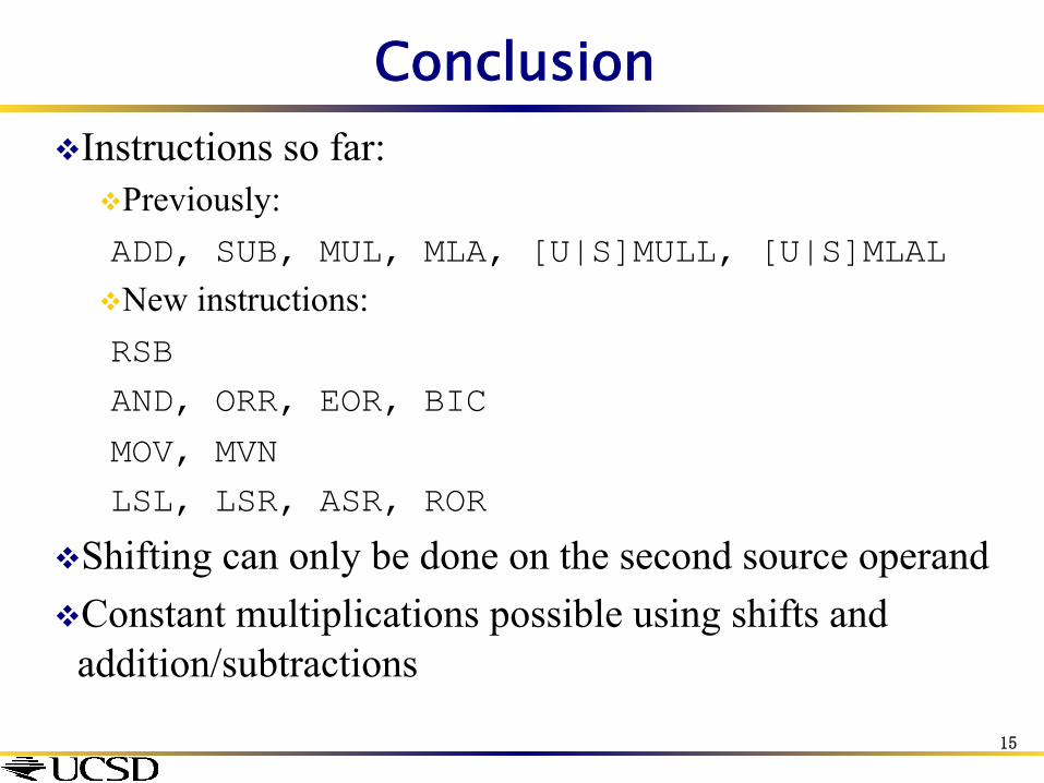
Conclusion v Instructions so far:
v Previously: ADD, SUB, MUL, MLA, [U|S]MULL, [U|S]MLAL v New instructions: RSB AND, ORR, EOR, BIC
MOV, MVN LSL, LSR, ASR, ROR
v Shifting can only be done on the second source operand v Constant multiplications possible using shifts and
addition/subtractions
15

Comments in Assembly
§ Another way to make your code more readable: comments!
§ Semicolon (;) is used for ARM comments § anything from semicolon to end of line is a
comment and will be ignored § Note: Different from C
§ C comments have format /* comment */, so they can span many lines
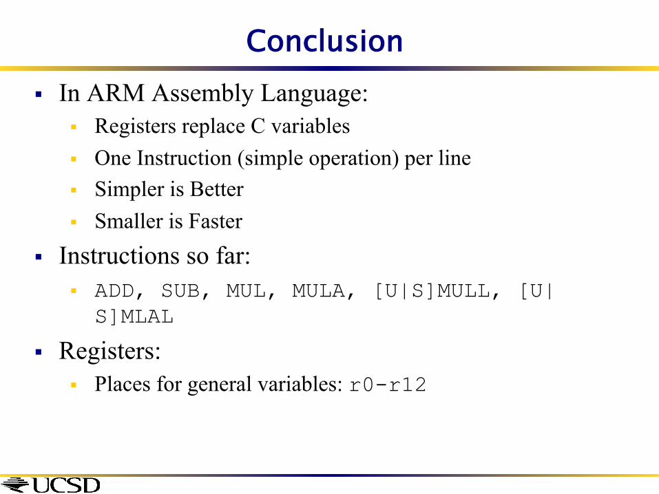
Conclusion § In ARM Assembly Language:
§ Registers replace C variables § One Instruction (simple operation) per line § Simpler is Better § Smaller is Faster
§ Instructions so far: § ADD, SUB, MUL, MULA, [U|S]MULL, [U|S]MLAL
§ Registers: § Places for general variables: r0-r12

Lecture 8: Data Transfer Instructions
CSE 30: Computer Organization and Systems Programming
Diba Mirza
Dept. of Computer Science and Engineering University of California, San Diego

Assembly Operands: Memory v Memory: Think of as single one-dimensional array where each cell
v Stores a byte size value v Is referred to by a 32 bit address e.g. value at 0x4000 is 0x0a
v Data is stored in memory as: variables, arrays, structures v But ARM arithmetic instructions only operate on registers,
never directly on memory. v Data transfer instructions transfer data between registers and
memory: v Memory to register or LOAD from memory to register v Register to memory or STORE from register to memory
0x0a 0x0b 0x0c 0x0d 0x4000 0x4001 0x4002 0x4003

Load/Store Instructions v The ARM is a Load/Store Architecture:
v Does not support memory to memory data processing operations.
v Must move data values into registers before using them.
v This might sound inefficient, but in practice isn’t: v Load data values from memory into registers. v Process data in registers using a number of data processing
instructions which are not slowed down by memory access. v Store results from registers out to memory.
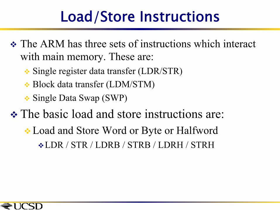
Load/Store Instructions v The ARM has three sets of instructions which interact
with main memory. These are: v Single register data transfer (LDR/STR) v Block data transfer (LDM/STM) v Single Data Swap (SWP)
v The basic load and store instructions are: v Load and Store Word or Byte or Halfword
v LDR / STR / LDRB / STRB / LDRH / STRH

Single register data transfer LDR STR Word LDRB STRB Byte LDRH STRH Halfword LDRSB Signed byte load LDRSH Signed halfword load
v Memory system must support all access sizes v Syntax:
v LDR{<cond>}{<size>} Rd, <address> v STR{<cond>}{<size>} Rd, <address> e.g. LDREQB

Data Transfer: Memory to Register v To transfer a word of data, we need to specify two things:
v Register: r0-r15 v Memory address: more difficult
v How do we specify the memory address of data to operate on?
v We will look at different ways of how this is done in ARM
Remember: Load value/data FROM memory
Addressing Modes
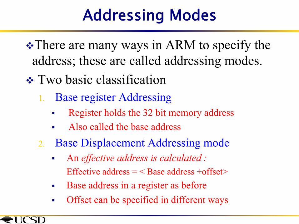
v There are many ways in ARM to specify the address; these are called addressing modes.
v Two basic classification 1. Base register Addressing
§ Register holds the 32 bit memory address § Also called the base address
2. Base Displacement Addressing mode § An effective address is calculated :
Effective address = < Base address +offset> § Base address in a register as before § Offset can be specified in different ways

Base Register Addressing Modes
v Specify a register which contains the memory address v In case of the load instruction (LDR) this is the memory
address of the data that we want to retrieve from memory v In case of the store instruction (STR), this is the memory
address where we want to write the value which is currently in a register
v Example: [r0] v specifies the memory address pointed to by the
value in r0
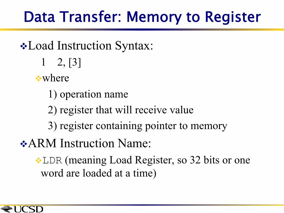
Data Transfer: Memory to Register
v Load Instruction Syntax: 1 2, [3] v where 1) operation name 2) register that will receive value 3) register containing pointer to memory
v ARM Instruction Name: v LDR (meaning Load Register, so 32 bits or one
word are loaded at a time)

Data Transfer: Memory to Register
v LDR r2,[r1] This instruction will take the address in r1, and then load a 4 byte value from the memory pointed to by it into register r2
v Note: r1 is called the base register
r1 0x200
Base Register
Memory
0xaa 0x200
r2
0xddccbbaa
Destination Register for LDR
0x201 0xbb 0xcc 0x202
0x203 0xdd

Data Transfer: Register to Memory
v STR r2,[r1] This instruction will take the address in r1, and then store a 4 byte value from the register r2 to the memory pointed to by r1.
v Note: r1 is called the base register
r1 0x200
Memory
0xaa 0x200
r2
0xddccbbaa 0x201 0xbb
0xcc 0x202 0x203 0xdd
Source Register for STR
Base Register

Base Displacement Addressing Mode
v To specify a memory address to copy from, specify two things:
v A register which contains a pointer to memory v A numerical offset (in bytes)
v The effective memory address is the sum of these two values.
v Example: [r0,#8] v specifies the memory address pointed to by the
value in r0, plus 8 bytes
Base Displacement Addressing Mode
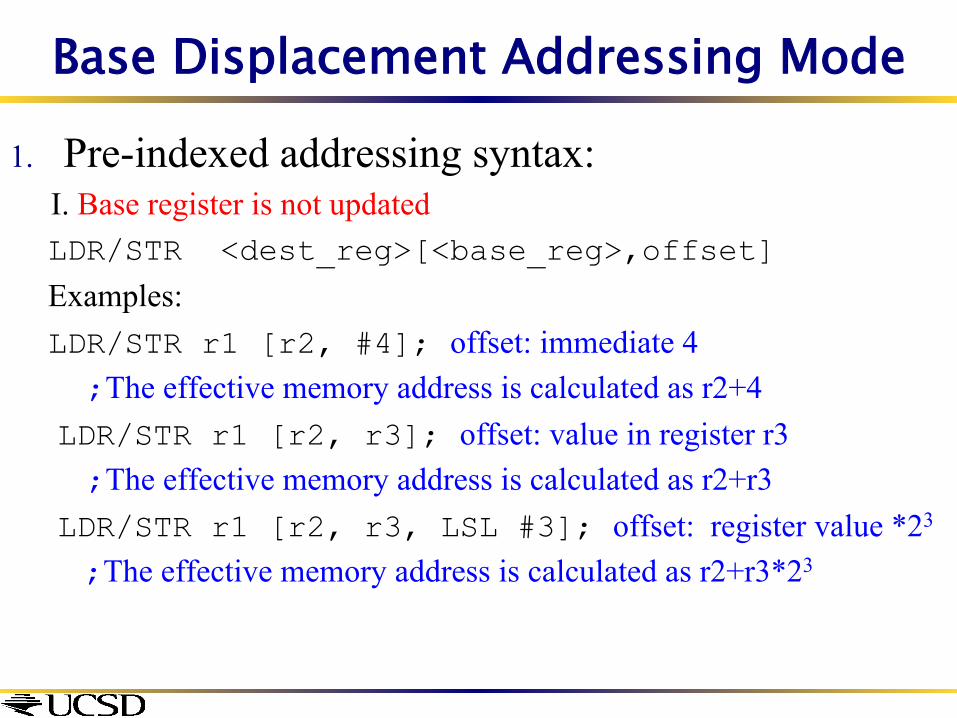
1. Pre-indexed addressing syntax: I. Base register is not updated
LDR/STR <dest_reg>[<base_reg>,offset]
Examples: LDR/STR r1 [r2, #4]; offset: immediate 4 ;The effective memory address is calculated as r2+4
LDR/STR r1 [r2, r3]; offset: value in register r3 ;The effective memory address is calculated as r2+r3
LDR/STR r1 [r2, r3, LSL #3]; offset: register value *23
;The effective memory address is calculated as r2+r3*23
Base Displacement Addressing Mode
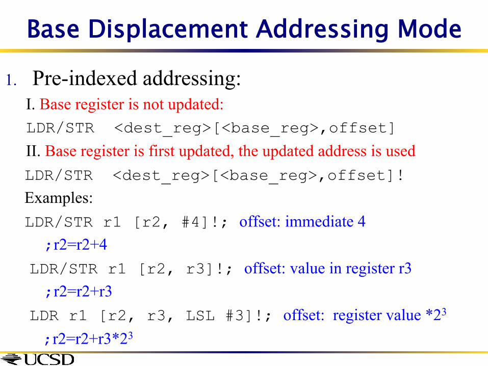
1. Pre-indexed addressing: I. Base register is not updated: LDR/STR <dest_reg>[<base_reg>,offset] II. Base register is first updated, the updated address is used
LDR/STR <dest_reg>[<base_reg>,offset]! Examples: LDR/STR r1 [r2, #4]!; offset: immediate 4 ;r2=r2+4
LDR/STR r1 [r2, r3]!; offset: value in register r3 ;r2=r2+r3
LDR r1 [r2, r3, LSL #3]!; offset: register value *23
;r2=r2+r3*23

Base Displacement, Pre-Indexed v Example: LDR r0,[r1,#12]
This instruction will take the pointer in r1, add 12 bytes to it, and then load the value from the memory pointed to by this calculated sum into register r0
v Example: STR r0,[r1,#-8] This instruction will take the pointer in r0, subtract 8 bytes from it, and then store the value from register r0 into the memory address pointed to by the calculated sum
v Notes: v r1 is called the base register v #constant is called the offset v offset is generally used in accessing elements of array or
structure: base reg points to beginning of array or structure

Pre indexed addressing
What is the value in r1 after the following instruction is executed? STR r2,[r1, #-4]!
r1 0x200
Base Register
Memory
0xaa 0x20_ r2
0xddccbbaa
Destination Register for LDR
0x20_ 0xbb 0xcc 0x20_
0x20_ 0xdd
A. 0x200 B. 0x1fc C. 0x196 D. None of the above

Base Displacement Addressing Mode
1. Post-indexed addressing:Base register is updated after load/store
LDR/STR <dest_reg>[<base_reg>] ,offset Examples: LDR/STR r1 [r2], #4; offset: immediate 4 ;Load/Store to/from memory address in r2, update r2=r2+4
LDR/STR r1 [r2], r3; offset: value in register r3 ;Load/Store to/from memory address in r2, update r2=r2+r3
LDR r1 [r2] r3, LSL #3; offset: register value left shifted
;Load/Store to/from memory address in r2, update r2=r2+r3*23

Post-indexed Addressing Mode
* Example: STR r0, [r1], #12 * If r2 contains 3, auto-increment base register to 0x20c by multiplying
this by 4: • STR r0, [r1], r2, LSL #2
* To auto-increment the base register to location 0x1f4 instead use: • STR r0, [r1], #-12
r1
0x200 Original
Base Register
Memory
0x5 0x200
r0
0x5 Source Register for STR
Offset
12 0x20c
r1 0x20c
Updated Base
Register

Using Addressing Modes Efficiently * Imagine an array, the first element of which is pointed to by the contents
of r0. * If we want to access a particular element,
then we can use pre-indexed addressing: • r1 is element we want. • LDR r2, [r0, r1, LSL #2]
* If we want to step through every
element of the array, for instance to produce sum of elements in the array, then we can use post-indexed addressing within a loop: • r1 is address of current element (initially equal to r0). • LDR r2, [r1], #4
Use a further register to store the address of final element,
so that the loop can be correctly terminated.
0
1
2
3
element
0
4
8
12
Memory Offset
r0
Pointer to start of array

Pointers vs. Values
v Key Concept: A register can hold any 32-bit value. That value can be a (signed) int, an unsigned int, a pointer (memory address), and so on
v If you write ADD r2,r1,r0 then r0 and r1 better contain values
v If you write LDR r2,[r0] then [r0] better contain a pointer
v Don’t mix these up!
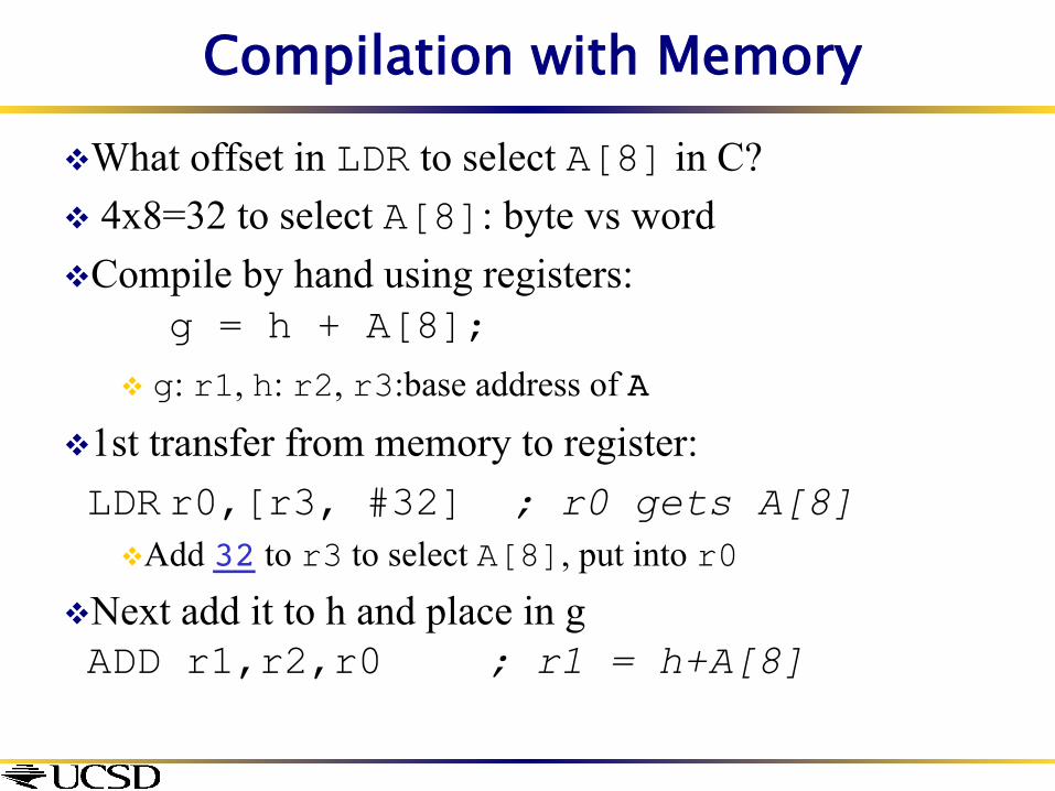
Compilation with Memory v What offset in LDR to select A[8] in C? v 4x8=32 to select A[8]: byte vs word v Compile by hand using registers:
g = h + A[8];v g: r1, h: r2, r3:base address of A
v 1st transfer from memory to register: LDR r0,[r3, #32] ; r0 gets A[8]
v Add 32 to r3 to select A[8], put into r0
v Next add it to h and place in g ADD r1,r2,r0 ; r1 = h+A[8]