Lecture 7 Access Control modified from slides of Lawrie Brown.
Upload
hasil-sharmaCategory
view
51download
0
Selected Chemical Engineering Operations
Selected Chemical Engineering
Operations
LECTURE - 7

Selected Chemical Engineering Operations
Size Reduction
• The term size reduction is applied to all the ways in which particles of solids are cut or broken into smaller pieces
• In the chemical Industry, size reduction or comminutionis usually carried out in order to increase the surface
• The energy required to effect size reduction is related to the internal structure of the material

Selected Chemical Engineering Operations
Size Reduction
• The process really consists of two parts
– first opening up any small fissures which are already present
– secondly forming new surfaces
• From the point of view of energy utilization
– size reduction is a very inefficient process
– only between 0.1 and 2.0 percent energy supplied to the
machine appears as increased surface energy in the solids
• The efficiency of the process is very much influenced by
– the manner in which the load is applied and its magnitude
– the nature of the force exerted is also very important
• To obtain the most effective utilization of energy
– the force should be only slightly in excess of the crushing
strength of the material

Selected Chemical Engineering Operations
Size Reduction
• Solids may be broken in many different ways, but only four of them are commonly used in size reduction machines:
– Compression: Particle disintegration by two rigid forces
– Impact: Particle concussion by a single rigid force
– Shear: Produced by a fluid or by particle-particle
interaction
– Attrition- arising from particles scraping against one
another or against a rigid surface

Selected Chemical Engineering Operations
Size Reduction
• In general
– compression is used for coarse reduction of hard solids, to give
relatively few fines
– impact gives coarse, medium, or fine products
– attrition yields very fine products from soft, nonabrasive materials
– cutting gives a definite particle size and sometimes a definite
shape, with few fine or no fine

Selected Chemical Engineering Operations
Principles of Comminution
• Comminution is a generic term for size reduction
– crushers and grinders are types of comminuting equipment
• An ideal crusher or grinder would
– have a large capacity
– require a small power input per unit of product
– yield a product of the single size or the size distribution desired
• The usual method of studying the performance of process equipment is to
– set up an ideal operation as a standard
– compare the characteristics of the actual equipment with those of
the ideal unit
– account for the difference between the two

Selected Chemical Engineering Operations
Characteristics of Comminuted Products
• The objective of crushing and grinding is to produce small particles from larger ones
• One measure of the efficiency of the operation is based on the energy required to create new surface
– the surface area of a unit mass of particles increases greatly as
the particle size is reduced
• Unlike an ideal crusher or grinder, an actual unit does not yield a uniform product
– whether the feed is uniformly sized or not

Selected Chemical Engineering Operations
Characteristics of Comminuted Products
• The product always consists of a mixture of particles
– ranging from a definite maximum size to very small particles
• The ratio of the diameters of the largest and smallest particles in a comminuted product is of the order of 104

Selected Chemical Engineering Operations
Energy and Power Requirements
• The cost of power is a major expenses in crushing and grinding
– so the factors that control this cost are important
• When the material fractures, new surface area is created
• Each new unit area of surface requires a certain amount of energy
• The energy required for fracture is a complicated function of the
– type of material
– Size
– Hardness
– other factors

Selected Chemical Engineering Operations
Energy and Power Requirements
• Some of the energy added is used to create the new surface, but a large portion of it appears as heat

Selected Chemical Engineering Operations
Energy and Power Requirements
• Crushing Efficiency (ηc)
– The ratio of the surface energy created by crushing to the energy
absorbed by the solid
– The energy absorbed by a unit mass of the material Wn is
– Where, es = surface energy per unit area
Awb and Awa = areas per unit mass of product and feed
– The surface energy created by fracture is small in comparison
with the total mechanical energy stored in the material
– Most of the energy is converted into heat
– Crushing efficiencies are therefore low and its range between
0.06 and 1 percent
c
wawbsn
)(
η
AAeW
−=

Selected Chemical Engineering Operations
Energy and Power Requirements
• Mechanical Efficiency
– The energy absorbed by the solid Wn is less than that fed to the
machine
– Part of the total energy input W is used to overcome friction in
the bearings and other moving parts
– the rest is available for crushing
– The energy input,
– The ratio of the energy absorbed to the energy input is ηm
cm
wawbs
m
nn
)(
ηηη
AAeWW
−==

Selected Chemical Engineering Operations
Energy and Power Requirements
• If m is the feed rate, the power required by the machine is
cm
wawbs )(
ηη
AAemWmP
−==
&&
−=
saasbbpcm
s 116
DD
emP
φφρηη
&

Selected Chemical Engineering Operations
Rittinger’s Law
• A crushing law proposed by Rittinger in 1867 states that
– the work required in crushing is proportional to the new surface
created
• This law, which is really no more than a hypothesis
– is equivalent to the statement that the crushing efficiency is
constant and, for a given machine and feed material
– is independent of the sizes of feed and product
• If the sphericities are equal for product and feed and the mechanical efficiency is constant
– the various constants can be combined into a single constant, Kr
−=
sasbr
11
DDK
m
P
&

Selected Chemical Engineering Operations
Rittinger’s Law
• Rittinger’s Law is applicable
– for fine grinding where the increase in surface per unit mass of
material is predominant
– energy input per unit mass of material is not too high
– feed size of less than 0.05 mm

Selected Chemical Engineering Operations
Kick’s Law
• In 1885 Kick proposed another law, based on stress analysis of plastic deformation within the elastic limit
• This law states that the work required for crushing a given mass of material is constant for same reduction ratio
– that is the ratio of initial particle size to the final particle size
– This law is more accurate than Rittinger’s law for coarse
crushing
• where the surface area per unit mass is considerably less
– Law is applicable for feed size of greater than 50 mm
sb
sa
k lnD
DK
m
P=
&

Selected Chemical Engineering Operations
Generalized Relation
• A generalized relation for both cases is the differential equation
– n = 1,2 leads to Kick’s law and Rittinger’s law, respectively
• Both Kick’s and Rittinger’s law have been shown to apply over limited ranges of particle size
• Kk and Kr are determined experimentally
– by tests in a machine of the type to used
– with the material to be crushed
n
s
s
D
DKd
m
Pd −=
&

Selected Chemical Engineering Operations
Bond’s Law
• A somewhat more realistic method of estimating the power required for crushing and grinding was proposed by Bond in 1952
• Bond postulated that
– the work required to form particles of size Dp from very large
feed is proportional to the square root of the surface to volume
ratio of the product , sp/vp
– Where Kb is a constant that depends on the type of machine and
one the material being crushed
– This is equivalent to a solution of generalized equation
• with n = 1.5 and a feed of infinite size
p
b
D
K
m
P=
&

Selected Chemical Engineering Operations
Bond’s Law
• A Work Index Wi is defined as
– the gross energy requirement in kWh per ton of feed needed to
reduce a large feed to such a size that 80 percent of the product
passes to 100 µm screen
– This definition leads to a relationship between Kb and Wi
– If Dp in millimeters, P in kilowatts and m in tons per hour
• If 80 percent of the feed passes a mesh size of Dpa
millimeters and 80 percent of the product a mesh of Dpb
millimeters, it gives
– The work index includes the friction in the crusher, and the
power given is gross power
ii
3
b 3162.010100 WWK =×= −
−=
papb
i
113162.0
DDW
m
P
&

Selected Chemical Engineering Operations
Problem
• 3 kW has to be supplied to a machine crushing material at the rate of 0.3 kg/s from 12.5 mm cubes to a product having the following sizes: 80% 3.175 mm, 10% 2.5 mm, and 10% 2.25 mm. What would be the power which would have to be supplied to this machine to crush 0.3 kg/s of the same material from 7.5 mm cube to 2.0 mm cube?

Selected Chemical Engineering Operations
Size Reduction Equipments
• Size reduction equipment is divided into
– Crushers
– Grinders
– Ultrafine grinders
– Cutting machines
• Crushers do the heavy work of breaking large pieces of solid material into small lumps
• A primary crusher operates on run-of-mine material
– accepting anything that comes from the mine face and breaking
it into 150 to 250 mm lumps
• A secondary crusher reduces these lumps to particles perhaps 6 mm in size
• Grinders reduce crushed feed to powder

Selected Chemical Engineering Operations
Size Reduction Equipments
• The product from an intermediate grinder might pass a 40 mesh screen
– most of the product from a fine grinder would pass a 200 mesh
screen with a 74 µm opening
• An ultrafine grinder accepts feed particles no longer than 6 mm
– the product size is typically 1 to 50 µm
• Cutters give particles of definite size and shape of 2 to 10 mm in length

Selected Chemical Engineering Operations
Type of Crushers
• Types of size reduction machines
– Crusher (Coarse and Fine)
• Crushers are slow speed machine for coarse reduction of large quantities of solids
– Jaw Crusher
– Gyratory Crusher
– Crushing Rolls

Selected Chemical Engineering Operations
Jaw Crusher
• Jaw crusher operate by compression and can break large lumps of very hard materials
– as in the primary and secondary reduction of rocks and ores
• In a Jaw crusher
– feed is admitted between two jaws
– set to form a V open at the top
– One Jaw, the fixed, or anvil, Jaw is nearly vertical and does not
move
– the other, the swinging Jaw, reciprocates in a horizontal plane
– It makes an angle of 20 to 300 with the anvil Jaw
– It is driven by an eccentric so that it applies great compressive
force to lumps caught between the Jaws
– Large lumps caught between the upper parts of the Jaw are
broken

Selected Chemical Engineering Operations
Jaw Crusher
– Drops into the narrower space below
– Recrushed the next time the jaws close
– After sufficient reduction they dropout the bottom of the machine
• The Jaws open and close 250 to 400 times per minute
• The Jaw faces are flat or slightly bulged; they may carry shallow horizontal grooves
• The greatest amount of motion is at the bottom of the V
– which means that there is little tendency for a crusher of this kind
to choke

Selected Chemical Engineering Operations
Jaw Crusher

Selected Chemical Engineering Operations
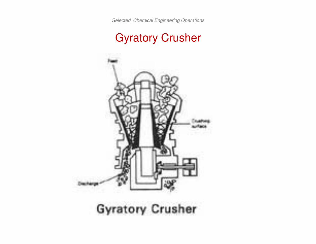
Gyratory Crusher
• A gyratory crusher may be looked upon as a jaw crusher
• Gyratory crusher consists of
– circular jaws, between which material is being crushed at some
points at all times
– A conical crushing head gyrates inside a funnel shaped casing,
open at the top
– The crushing head is carried on a heavy shaft pivoted at the top
of the machine
– An eccentric drives the bottom end of the shaft
– At any point on the periphery of the casing, therefore, the bottom
of the crushing head moves toward
– Then away from the stationary wall
– Solids caught in the V shaped space between the head and the
casing

Selected Chemical Engineering Operations
Gyratory Crusher
– are broken and re-broken until they pass out the bottom
– The crushing head is free to rotate on the shaft
– It turns slowly because of friction with the material being crushed
• The speed of the crushing head is typically 125 to 425 gyrations/min
• Because some parts of the crushing head is working at all times
– the discharge from a gyratory is continuous instead of
intermittent as in a jaw crusher
• Less maintenance is required than with a jaw crusher
• The power requirement per ton of material crushed is smaller

Selected Chemical Engineering Operations
Gyratory Crusher
• The capacity of a gyratory crusher varies with
– the jaw setting
– the impact strength of the feed
– the speed of gyration of the machine
• The capacity is almost independent of the compressive strength of the material being crushed

Selected Chemical Engineering Operations
Gyratory Crusher
Selected Chemical Engineering Operations
Gyratory Crusher

Selected Chemical Engineering Operations
Gyratory Crusher

Selected Chemical Engineering Operations
Smooth Roll Crusher
• Two heavy smooth faced metal rolls turning on parallel horizontal axes
• Particles of feed caught between the rolls are broken in compression and dropout below
• The rolls turn towards each other at the same speed
• They have relatively narrow faces and are large in diameter
– so that they can nip moderately large lumps
• Roll speeds ranges from 50 to 300 r/min
• Smooth roll crushers are secondary crusher
– with feeds 12 to 75 mm in size and product 12 mm to about 1
mm
Selected Chemical Engineering Operations
Smooth Roll Crusher
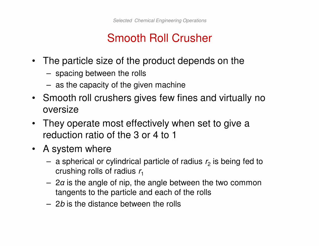
• The particle size of the product depends on the
– spacing between the rolls
– as the capacity of the given machine
• Smooth roll crushers gives few fines and virtually no oversize
• They operate most effectively when set to give a reduction ratio of the 3 or 4 to 1
• A system where
– a spherical or cylindrical particle of radius r2 is being fed to
crushing rolls of radius r1
– 2α is the angle of nip, the angle between the two common
tangents to the particle and each of the rolls
– 2b is the distance between the rolls

Selected Chemical Engineering Operations
Smooth Roll Crusher
• It is shown from the geometry of the system that the angle of the nip is given by
• The maximum size of the product is approximately equal to 2b
• For steel rolls, the angle of nip will be not greater than about 320
12
1cosrr
br
+
+=α

Selected Chemical Engineering Operations
Smooth Roll Crusher

Selected Chemical Engineering Operations
Smooth Roll Crusher
• A certain set of crushing rolls has rolls of 100 cm diameter by 38 cm width face. They are set so that the crushing surfaces are 1.25 cm apart at the narrowest point. The manufacturer recommends that they may be run at 50 to 100 r.p.m. They are to crush a rock having a specific gravity of 2.35, and the angle of nip is 300C. What are the maximum permissible size of feed and the maximum actual capacity in tons per hour, if the actual capacity is 12 percent of the theoretical.
• Ans: 25.25 tons/hr

Selected Chemical Engineering Operations
Grinders
• The term grinder describes a variety of size reduction machines for intermediate duty
• The product from a crusher is often fed to a grinder, in which it is reduced to a powder
• Some grinders are given below
– Hammer Mills: impactors
– Rolling-Compression Mills
– Attrition Mills
– Tumbling Mills

Selected Chemical Engineering Operations
Hammer Mills: impactors
• These mills all contain a high-speed rotor turning inside a cylindrical casing, the shaft is usually horizontal
• Feed dropped into the top of the casing is broken and falls out through a bottom opening
• In a hammer mill the particles are broken by sets of swing hammers pinned to rotor disk
• A particle of feed entering the grinding zone cannot escape being struck by the hammers
• It shatters into pieces
– which fly against a stationary anvil plate inside the casing and
break into still smaller fragments

Selected Chemical Engineering Operations
Hammer Mills: impactors
– these in turn are rubbed into powder by the hammers
– pushed through a grate or screen that covers the discharge
opening
• Hammer mills grind almost anything
– tough fibrous, solid like bark or leather, steel turnings, soft wet
pastes, sticky clay, hard rock
• For fine reduction they are limited to the softer materials
• An impactor resembles a heavy duty hammer mill except that contain no grate or screen
• Particles are broken by impact alone, without the rubbing action characteristic of a hammer mill

Selected Chemical Engineering Operations
Hammer Mills: impactors
Selected Chemical Engineering Operations
Rolling Compression Mill
• In this kind of mill
– the solid particles are caught and crushed between a rolling
member and face of the ring or casing
– vertical cylindrical rollers passes outwards with great force
against a stationary anvil ring or bull ring
– they are driven at moderate speeds in a circular path
– Plows lift the solid lumps from the floor of the mill
– direct them between the ring and the rolls, where reduction takes
place
– Product is swept out of the mill by a stream of air to a classifier
separator
– from which oversize particles are returned to the mill for further
reduction
• Mills of this kind find most application in the reduction of lime stone, cement clinker, and coal

Selected Chemical Engineering Operations
Attrition Mill
• In an attrition mill
– particles of soft solids are rubbed between the grooved flat faces
of rotating cylindrical disks
• The axis of the disk is usually horizontal, sometimes vertical
• In a single runner mill
– one disk is stationary and one rotates
• In a double runner machine
– both disks are driven at high speed in opposite direction
• Feed enters through an opening in the hub of one of the disk
• It passes outwards through the narrowgap between the disks

Selected Chemical Engineering Operations
Attrition Mill
• Discharges from the periphery into a stationary casing
• The width of the gap, within limits is adjustable
• At least one grinding plate is spring mounted so that the disks can separate
– if unbreakable material gets into the mill
• Mills with different patterns of grooves corrugations, or teeth of the disks perform a variety of operations
– Grinding, cracking, granulating, and shredding
– Even some operations not related to size reduction at all, such
as blending and feather curling
• Double runner mills, in general grind to finer products than single runner mills but process softer feeds

Selected Chemical Engineering Operations
Attrition Mill
• Air is often drawn through the mill to remove the product and prevent choking
• The energy required depends strongly on
– the nature of the feed
– the degree of reduction accomplished
– much than in the mills and crushers described so far

Selected Chemical Engineering Operations
Attrition Mill

Selected Chemical Engineering Operations
Tumbling Mill
• A cylindrical shell slowly turning about a horizontal axis
– filled to about half its volume with a solid grinding medium
forms a tumbling mill
• The shell is usually steel lined with high carbon steel plate, porcelain, silica rock, or rubber
• The grinding medium is
– metal rods in a rod mill
– lengths of chain or balls of metal
– rubber or wood in a ball mill
– flint pebbles or porcelain or zircon spheres in a pebble mill
• For intermediate and fine reduction or abrasive materials tumbling mills are unequaled
• Tumbling mills may be batch or continuous

Selected Chemical Engineering Operations
Tumbling Mill
• In a batch machine
– a measured quantity of the solid to be ground is loaded into the
mill through an opening in the shell
– the opening is then closed and the mill turned on the several
hours
– it is then stopped and the product is discharged
• In a continuous mill
– the solid flows steadily through the revolving shell
– entering at one end through a hollow trunnion
– leaving at the other end through trunnion or through peripheral
openings in the shell

Selected Chemical Engineering Operations
Tumbling Mill
• In all tumbling mills
– the grinding elements are carried up the side of the shell nearly
to the top
– from where they fall on the particles underneath
– The energy expended in lifting the grinding units is utilized in
reducing the size of the particle

Selected Chemical Engineering Operations
Tumbling Mill

Selected Chemical Engineering Operations
Action in Tumbling Mill
• The load of balls in ball or tube mill is normally such that
– the balls occupy about one-half volume of the mill
• The void fraction in the mass of balls, when at rest, is typically 0.4
• The grinding may be done with
– Dry solids
– More commonly the feed is a suspension of the particles in water
• This increase both the capacity and efficiency of the mill

Selected Chemical Engineering Operations
Action in Tumbling Mill
• When the mill is rotated
– the balls are picked up by the mill wall and carried nearly at the
top
– where they break contact with the wall and fall to the bottom to
be picked up again
– Centrifugal force keeps the ball in contact with the wall and with
each other
• During the upward movement
– while in contact with the wall the balls do some grinding by
slipping and rolling over each other
• Most of the grinding occurs at the zone of impact
– where the free falling balls strike the bottom of the mill

Selected Chemical Engineering Operations
Action in Tumbling Mill
• The faster the mill is rotated
– the farther the balls are carried up inside the mill
– the greater the power consumption
• The added power is profitably used
– because the higher the balls are when they are released
– the greater the impact at the bottom and the larger the
productive capacity of the mill
• If the speed is too high
– the balls are carried over and the mill is said to be centrifuging
• The speed at which centrifuging occurs is called the critical speed
– little or no grinding is done when a mill is centrifuging
• operating speed must be less than critical

Selected Chemical Engineering Operations
Action in Tumbling Mill
• The speed at which the outermost ball lose the contact with the wall of the mill depends on
– the balance between gravitational and centrifugal forces
• The centripetal component of the force of gravity opposes the centrifugal force
– As long as the centrifugal force exceeds the centripetal force
– the ball will not break contact with the wall
• As the angle α decreases
– the centripetal force increases
• Unless the speed exceeds the critical
– a point is reached where the opposing forces are equal and the
particle is ready to fall

Selected Chemical Engineering Operations
Action in Tumbling Mill
• The angle at which this occurs is found by equating the two forces
• At critical speed, α = 0, cosα = 1, and n becomes the critical speed nc
• Tumbling mills run at 65 to 80 percent of the critical speed
{ }
g
rRn
g
rRnm
g
mg
cc
)(4cos
)(4cos
22
22
−=
−=
πα
πα
rR
gnc
−=
π2
1

Selected Chemical Engineering Operations
Open Circuit and Close Circuit Operation
• In many mills the feed is broken into particles of satisfactory size by passing it once through the mill
• When no attempt is made to return oversize particles to the machine for further reduction
– the mill is said be operating in open circuit
• This may require excessive amount of power
– much energy is wasted in regrinding particles that are already
fine enough
• Thus it is often economical to remove partially ground material from the mill and pass it through a size separation device
– The undersize becomes the product and oversize is returned to
be reground

Selected Chemical Engineering Operations
Open Circuit and Close Circuit Operation
• The separation device is sometimes inside the mill or as is more common, it is outside the mill
• Close circuit operation is the term applied to the action of a mill and separator connected
– so that the oversize particles are returned to the mill

Selected Chemical Engineering Operations
Open Circuit and Close Circuit Operation

Selected Chemical Engineering Operations
Thank You