Lecture 7: File Systems Networkinglabe.felk.cvut.cz/~stepan/AE3B33OSD/OSD-Lecture-7.pdf ·...
65
Lecture 7: File Systems Networking
Transcript of Lecture 7: File Systems Networkinglabe.felk.cvut.cz/~stepan/AE3B33OSD/OSD-Lecture-7.pdf ·...
Lecture 7: File Systems
Networking
Lecture 7 / Page 2 AE3B33OSD 2011
Contents
Files & File System Interface
Directories & their Organization
File System Implementation
Disk Space Allocation
File System Efficiency & Reliability
Networking
OSI - Open System Interconnection Model
Ethernet
IP
UDP
TCP
Lecture 7 / Page 3 AE3B33OSD 2011
File Systems Interface
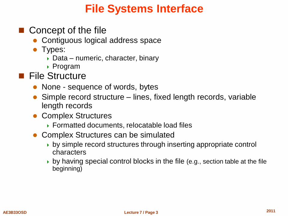
Concept of the file Contiguous logical address space Types:
Data – numeric, character, binary Program
File Structure None - sequence of words, bytes
Simple record structure – lines, fixed length records, variable length records
Complex Structures Formatted documents, relocatable load files
Complex Structures can be simulated by simple record structures through inserting appropriate control
characters
by having special control blocks in the file (e.g., section table at the file beginning)
Lecture 7 / Page 4 AE3B33OSD 2011
File Systems Interface (2)
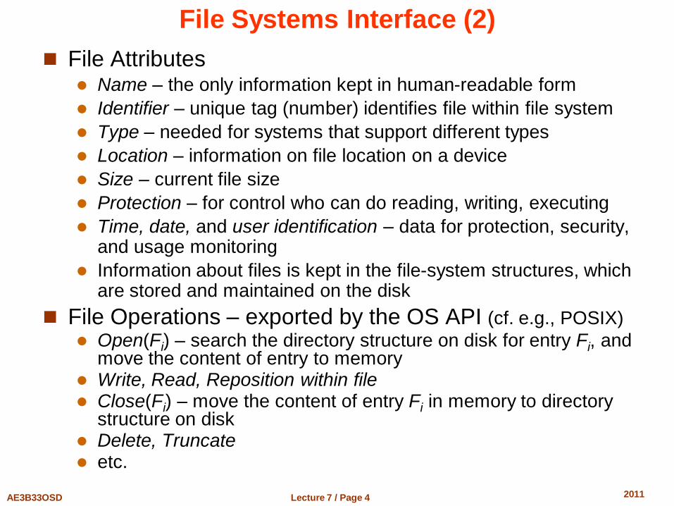
File Attributes Name – the only information kept in human-readable form
Identifier – unique tag (number) identifies file within file system
Type – needed for systems that support different types
Location – information on file location on a device
Size – current file size
Protection – for control who can do reading, writing, executing
Time, date, and user identification – data for protection, security, and usage monitoring
Information about files is kept in the file-system structures, which are stored and maintained on the disk
File Operations – exported by the OS API (cf. e.g., POSIX)
Open(Fi) – search the directory structure on disk for entry Fi, and move the content of entry to memory
Write, Read, Reposition within file Close(Fi) – move the content of entry Fi in memory to directory
structure on disk Delete, Truncate etc.
Lecture 7 / Page 5 AE3B33OSD 2011
Directory Structure
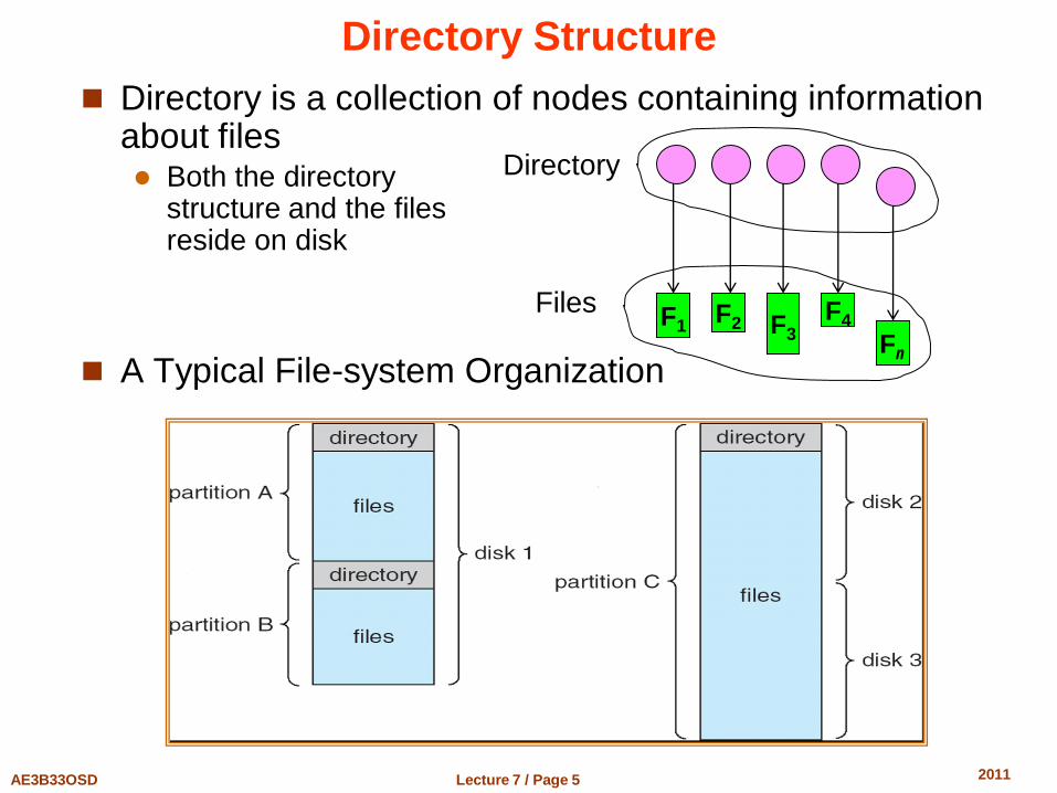
Directory is a collection of nodes containing information about files Both the directory
structure and the files reside on disk
A Typical File-system Organization
F1 F2 F3
F4
Fn
Directory
Files
Lecture 7 / Page 6 AE3B33OSD 2011
Logical Organization the Directories
Operations Performed on Directory Search for a file Create a file Delete a file List a directory Rename a file Traverse the file system
Organize directories to get Efficiency – locating a file quickly
The same file can have several different names
Naming – convenient to users Two users can have same name for different files
Grouping – logical grouping of files by properties, (e.g., all Java programs, all games, …)
Lecture 7 / Page 7 AE3B33OSD 2011
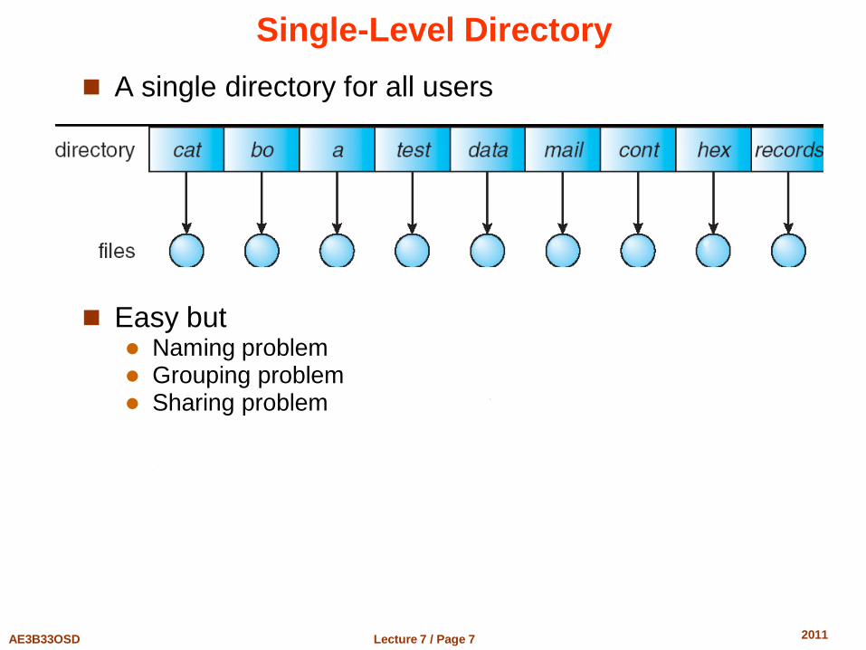
Single-Level Directory
A single directory for all users
Easy but Naming problem Grouping problem Sharing problem
Lecture 7 / Page 8 AE3B33OSD 2011
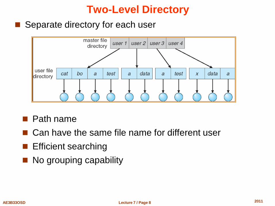
Two-Level Directory
Separate directory for each user
Path name
Can have the same file name for different user
Efficient searching
No grouping capability
Lecture 7 / Page 9 AE3B33OSD 2011
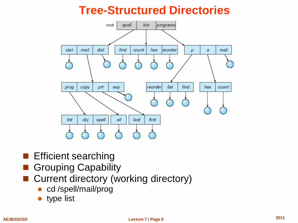
Tree-Structured Directories
Efficient searching Grouping Capability Current directory (working directory)
cd /spell/mail/prog type list
Lecture 7 / Page 10 AE3B33OSD 2011
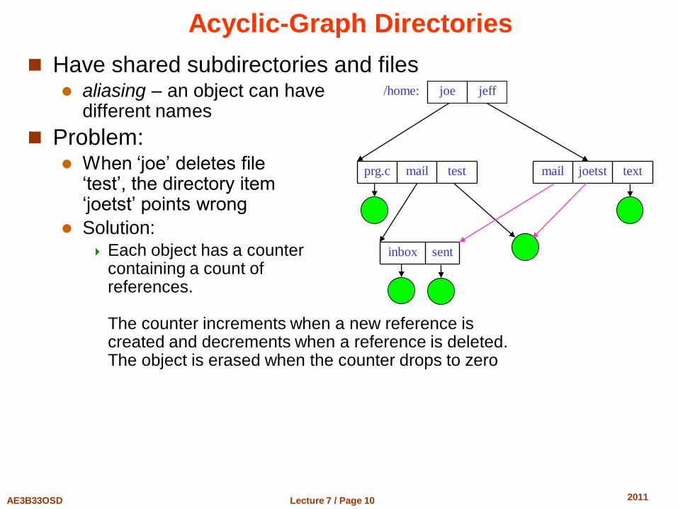
Acyclic-Graph Directories
Have shared subdirectories and files aliasing – an object can have
different names
Problem: When ‘joe’ deletes file
‘test’, the directory item ‘joetst’ points wrong
Solution: Each object has a counter
containing a count of references. The counter increments when a new reference is created and decrements when a reference is deleted. The object is erased when the counter drops to zero
test mail prg.c
sent inbox
text joetst mail
jeff joe /home:
Lecture 7 / Page 11 AE3B33OSD 2011
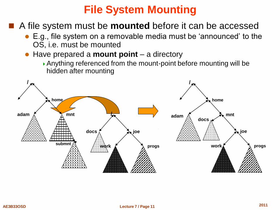
File System Mounting
A file system must be mounted before it can be accessed E.g., file system on a removable media must be ‘announced’ to the
OS, i.e. must be mounted
Have prepared a mount point – a directory Anything referenced from the mount-point before mounting will be
hidden after mounting
/
home
adam mnt docs
joe
progs work
docs
/
joe
progs work
/
home
adam mnt
submnt
Lecture 7 / Page 12 AE3B33OSD 2011
File Sharing
Sharing of files on multi-user systems is desirable
Sharing may be done through a protection scheme
On distributed systems, files may be shared across a network Network File System (NFS) is a common distributed file-sharing
method
User IDs identify users, allowing permissions and protections to be per-user
Group IDs allow users to be in groups, permitting group access rights POSIX rwx|rwx|rwx scheme
U G O ACL – Access Control Lists (Windows, some UNIXes)
Lecture 7 / Page 13 AE3B33OSD 2011
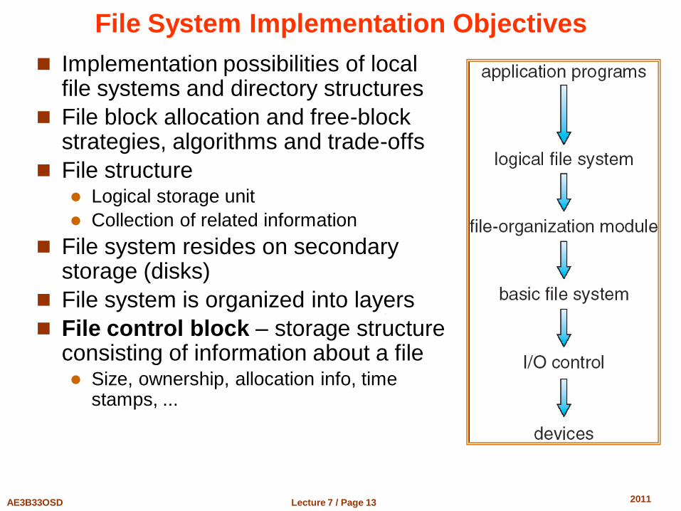
File System Implementation Objectives
Implementation possibilities of local file systems and directory structures
File block allocation and free-block strategies, algorithms and trade-offs
File structure Logical storage unit
Collection of related information
File system resides on secondary storage (disks)
File system is organized into layers
File control block – storage structure consisting of information about a file Size, ownership, allocation info, time
stamps, ...
Lecture 7 / Page 14 AE3B33OSD 2011
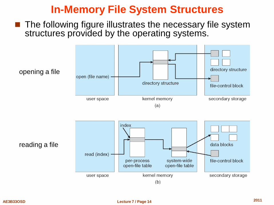
In-Memory File System Structures
The following figure illustrates the necessary file system structures provided by the operating systems.
opening a file
reading a file
Lecture 7 / Page 15 AE3B33OSD 2011
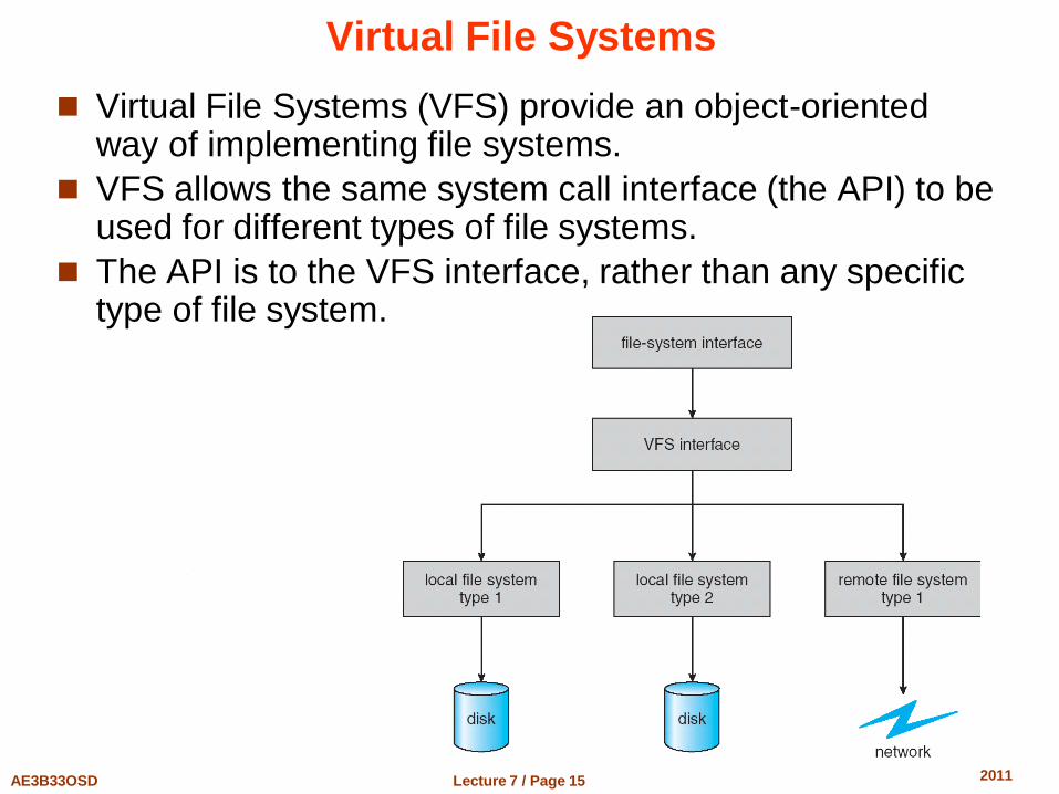
Virtual File Systems
Virtual File Systems (VFS) provide an object-oriented way of implementing file systems.
VFS allows the same system call interface (the API) to be used for different types of file systems.
The API is to the VFS interface, rather than any specific type of file system.
Lecture 7 / Page 16 AE3B33OSD 2011
Directory Implementation
Linear list of file names with pointer to the data blocks. simple to program
time-consuming to execute
Hash Table – linear list with hash data structure. decreases directory search time
collisions – situations where two file names hash to the same location
fixed size
Complex data structure – e.g., B+ tree NTFS in MS Windows
Lecture 7 / Page 17 AE3B33OSD 2011
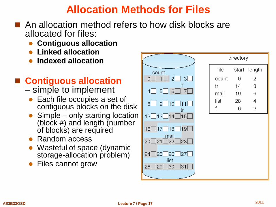
Allocation Methods for Files
An allocation method refers to how disk blocks are allocated for files: Contiguous allocation Linked allocation Indexed allocation
Contiguous allocation
– simple to implement Each file occupies a set of
contiguous blocks on the disk Simple – only starting location
(block #) and length (number of blocks) are required
Random access Wasteful of space (dynamic
storage-allocation problem) Files cannot grow
Lecture 7 / Page 18 AE3B33OSD 2011
Extent-Based Systems
Many newer file systems (e.g., Veritas File System) use a modified contiguous allocation scheme
Extent-based file systems allocate disk blocks in extents
An extent is a contiguous block of disks Extents are allocated for file growth
A file consists of one or more extents
Lecture 7 / Page 19 AE3B33OSD 2011
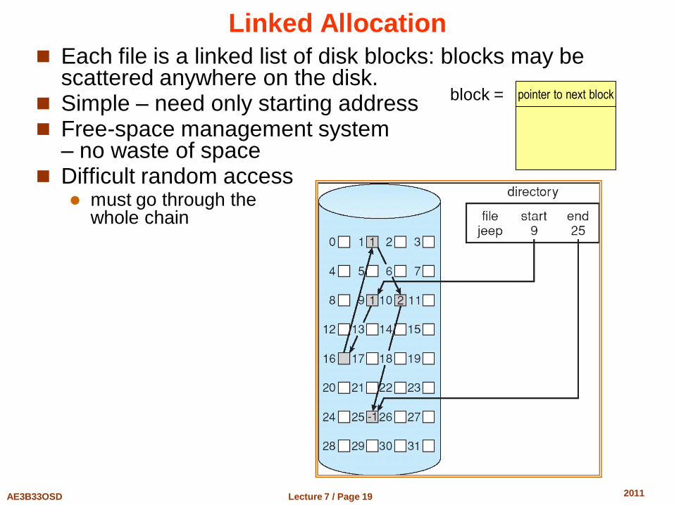
Linked Allocation
Each file is a linked list of disk blocks: blocks may be scattered anywhere on the disk.
Simple – need only starting address Free-space management system
– no waste of space Difficult random access
must go through the whole chain
pointer to next block block =
Lecture 7 / Page 20 AE3B33OSD 2011
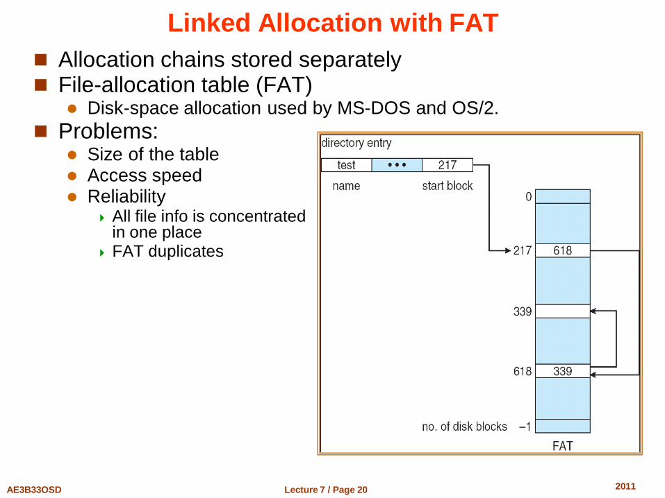
Linked Allocation with FAT
Allocation chains stored separately File-allocation table (FAT)
Disk-space allocation used by MS-DOS and OS/2.
Problems: Size of the table Access speed Reliability
All file info is concentrated in one place
FAT duplicates
Lecture 7 / Page 21 AE3B33OSD 2011
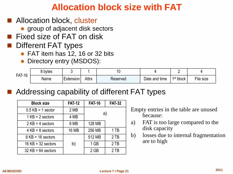
Allocation block size with FAT
Allocation block, cluster group of adjacent disk sectors
Fixed size of FAT on disk Different FAT types
FAT item has 12, 16 or 32 bits Directory entry (MSDOS):
Addressing capability of different FAT types
File size 1st block Date and time Reserved Attrs Extension Name FAT-16
4 2 4 10 1 3 8 bytes
2 TB 2 GB 32 KB = 64 sectors
2 TB 1 GB 16 KB = 32 sectors
2 TB 512 MB
b)
8 KB = 16 sectors
1 TB 256 MB 16 MB 4 KB = 8 sectors
128 MB 8 MB 2 KB = 4 sectors
4 MB 1 KB = 2 sectors a)
2 MB 0.5 KB = 1 sector
FAT-32 FAT-16 FAT-12 Block size
Empty entries in the table are unused because:
a) FAT is too large compared to the disk capacity
b) losses due to internal fragmentation are to high
Lecture 7 / Page 22 AE3B33OSD 2011
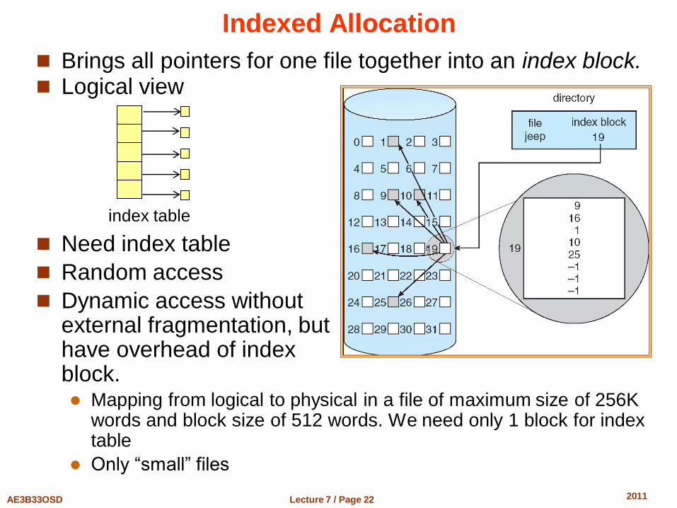
Indexed Allocation
Brings all pointers for one file together into an index block. Logical view
Need index table
Random access
Dynamic access without external fragmentation, but have overhead of index block. Mapping from logical to physical in a file of maximum size of 256K
words and block size of 512 words. We need only 1 block for index table
Only “small” files
index table
Lecture 7 / Page 23 AE3B33OSD 2011
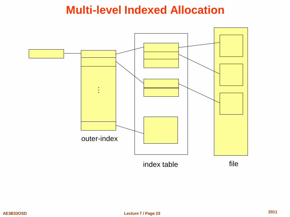
Multi-level Indexed Allocation
outer-index
index table file
Lecture 7 / Page 24 AE3B33OSD 2011
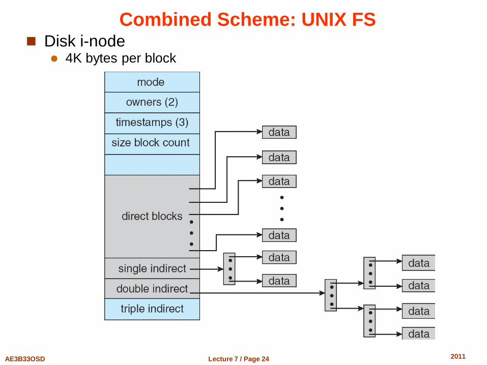
Combined Scheme: UNIX FS Disk i-node
4K bytes per block
Lecture 7 / Page 25 AE3B33OSD 2011
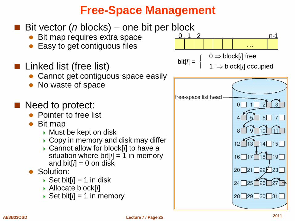
Free-Space Management
Bit vector (n blocks) – one bit per block Bit map requires extra space Easy to get contiguous files
Linked list (free list)
Cannot get contiguous space easily No waste of space
Need to protect:
Pointer to free list Bit map
Must be kept on disk Copy in memory and disk may differ Cannot allow for block[i] to have a
situation where bit[i] = 1 in memory and bit[i] = 0 on disk
Solution: Set bit[i] = 1 in disk Allocate block[i] Set bit[i] = 1 in memory
…
0 1 2 n-1
bit[i] =
0 block[i] free
1 block[i] occupied
Lecture 7 / Page 26 AE3B33OSD 2011
Directory Implementation
Linear list of file names with pointer to the data blocks simple to implement
time-consuming to execute
directory can grow and shrink
Hash Table – linear list with hash data structure decreases directory search time
collisions – situations where two file names hash to the same location
fixed size
Lecture 7 / Page 27 AE3B33OSD 2011
File System Efficiency and Performance
Efficiency dependent on: disk allocation and directory algorithms types of data kept in file’s directory entry
Performance disk cache – separate section of main memory for frequently
used blocks free-behind and read-ahead – techniques to optimize sequential
access improve PC performance by dedicating section of memory as
virtual disk, or RAM disk
Lecture 7 / Page 28 AE3B33OSD 2011
Recovery from a Crash
Consistency checking – compares data in directory structure with data blocks on disk, and tries to fix inconsistencies
Use system programs to back up data from disk to another storage device (floppy disk, magnetic tape, other magnetic disk, optical)
Recover lost file or disk by restoring data from backup
Lecture 7 / Page 29 AE3B33OSD 2011
Log Structured File Systems
Log structured (or journaling) file systems record each update to the file system as a transaction similar to database systems
All transactions are written to a log A transaction is considered committed once it is written to the log
However, the file system may not yet be updated
The transactions in the log are asynchronously written to the file system When the file system is modified, the transaction is removed from
the log
If the file system crashes, all remaining transactions in the log must still be performed
Used by NTFS file system
Lecture 7 / Page 30 AE3B33OSD 2011
Short introduction to Networking
Lecture 7 / Page 31 AE3B33OSD 2011
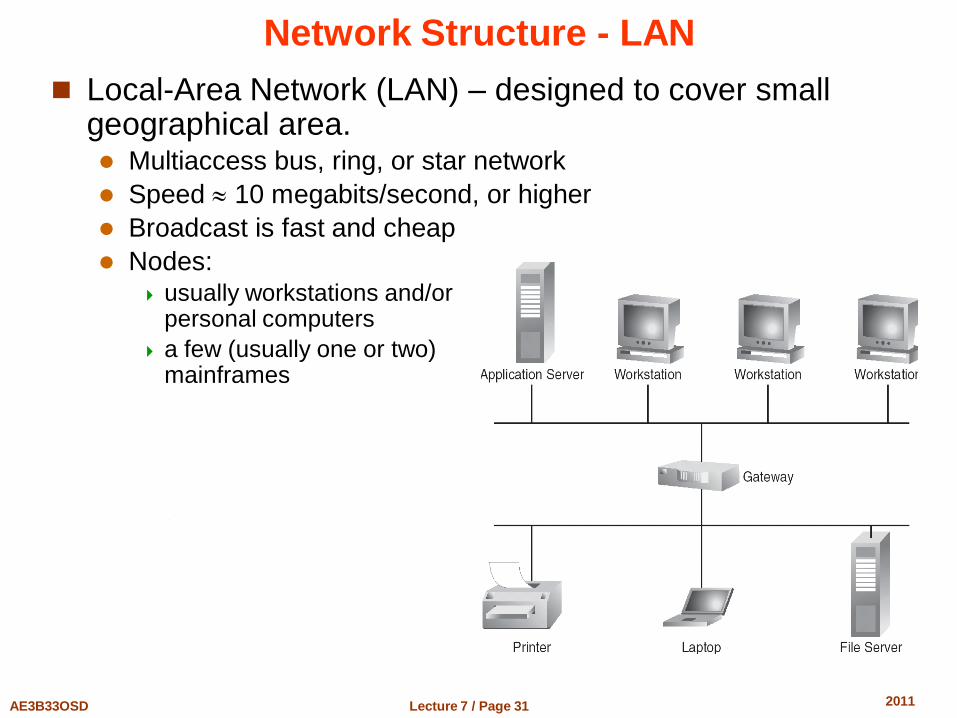
Network Structure - LAN
Local-Area Network (LAN) – designed to cover small geographical area. Multiaccess bus, ring, or star network
Speed 10 megabits/second, or higher
Broadcast is fast and cheap
Nodes: usually workstations and/or
personal computers
a few (usually one or two) mainframes
Lecture 7 / Page 32 AE3B33OSD 2011
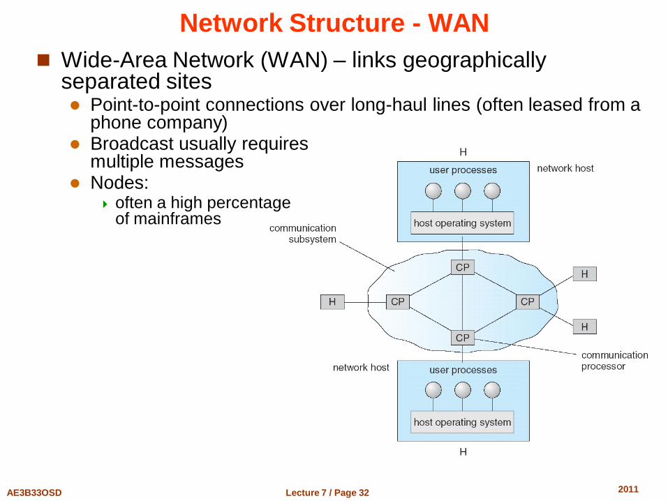
Network Structure - WAN
Wide-Area Network (WAN) – links geographically separated sites Point-to-point connections over long-haul lines (often leased from a
phone company) Broadcast usually requires
multiple messages Nodes:
often a high percentage of mainframes
Lecture 7 / Page 33 AE3B33OSD 2011
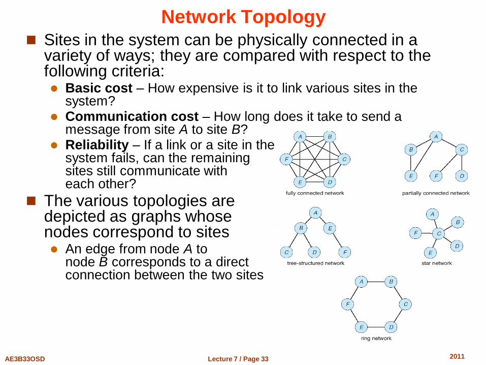
Network Topology Sites in the system can be physically connected in a
variety of ways; they are compared with respect to the following criteria: Basic cost – How expensive is it to link various sites in the
system? Communication cost – How long does it take to send a
message from site A to site B? Reliability – If a link or a site in the
system fails, can the remaining sites still communicate with each other?
The various topologies are depicted as graphs whose nodes correspond to sites An edge from node A to
node B corresponds to a direct connection between the two sites
Lecture 7 / Page 34 AE3B33OSD 2011
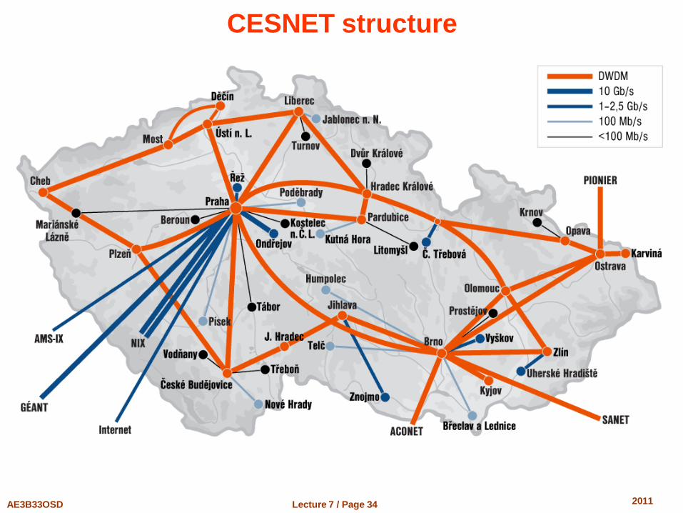
CESNET structure
Lecture 7 / Page 35 AE3B33OSD 2011
Communication Structure
The design of a communication network must address four basic issues:
Naming and name resolution How do two processes locate each other to communicate?
Routing strategies How are messages sent through the network?
Connection strategies How do two processes send a sequence of messages?
Contention The network is a shared resource, so how do we resolve
conflicting demands for its use?
Lecture 7 / Page 36 AE3B33OSD 2011
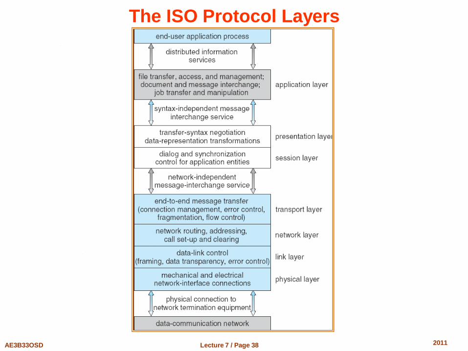
Communication Protocol
Physical layer – handles the mechanical and electrical details of the physical transmission of a bit stream
Data-link layer – handles the frames, or fixed-length parts of packets, including any error detection and recovery that occurred in the physical layer
Network layer – provides connections and routes packets in the communication network, including handling the address of outgoing packets, decoding the address of incoming packets, and maintaining routing information for proper response to changing load levels
The communication network is partitioned into the
following multiple layers:
Lecture 7 / Page 37 AE3B33OSD 2011
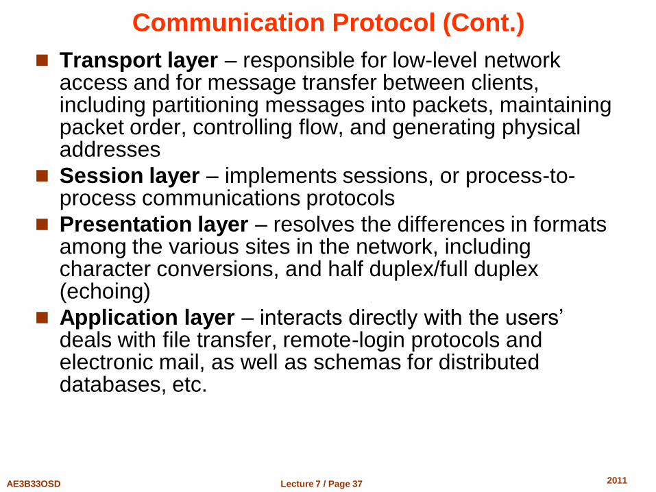
Communication Protocol (Cont.)
Transport layer – responsible for low-level network access and for message transfer between clients, including partitioning messages into packets, maintaining packet order, controlling flow, and generating physical addresses
Session layer – implements sessions, or process-to-process communications protocols
Presentation layer – resolves the differences in formats among the various sites in the network, including character conversions, and half duplex/full duplex (echoing)
Application layer – interacts directly with the users’ deals with file transfer, remote-login protocols and electronic mail, as well as schemas for distributed databases, etc.
Lecture 7 / Page 38 AE3B33OSD 2011
The ISO Protocol Layers
Lecture 7 / Page 39 AE3B33OSD 2011
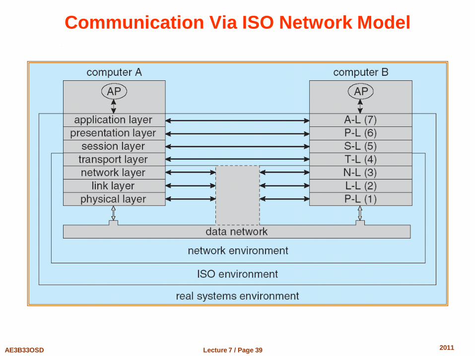
Communication Via ISO Network Model
Lecture 7 / Page 40 AE3B33OSD 2011
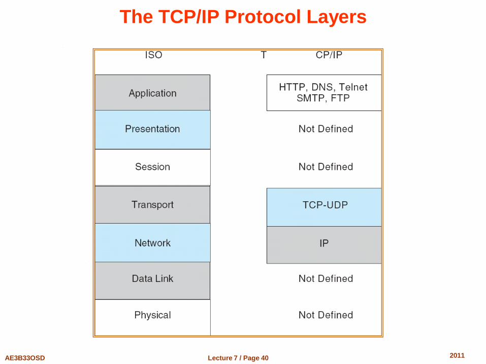
The TCP/IP Protocol Layers
Lecture 7 / Page 41 AE3B33OSD 2011
Design Issues
Transparency – the distributed system should appear as a conventional, centralized system to the user
Fault tolerance – the distributed system should continue to function in the face of failure
Scalability – as demands increase, the system should easily accept the addition of new resources to accommodate the increased demand
Clusters – a collection of semi-autonomous machines that acts as a single system
Lecture 7 / Page 42 AE3B33OSD 2011
Example: Networking
The transmission of a network packet between hosts on an Ethernet network
Every host has a unique IP address and a corresponding Ethernet (MAC) address
Communication requires both addresses
Domain Name Service (DNS) can be used to acquire IP addresses
Address Resolution Protocol (ARP) is used to map MAC addresses to IP addresses
If the hosts are on the same network, ARP can be used If the hosts are on different networks, the sending host will send
the packet to a router which routes the packet to the destination network
Lecture 7 / Page 43 AE3B33OSD 2011
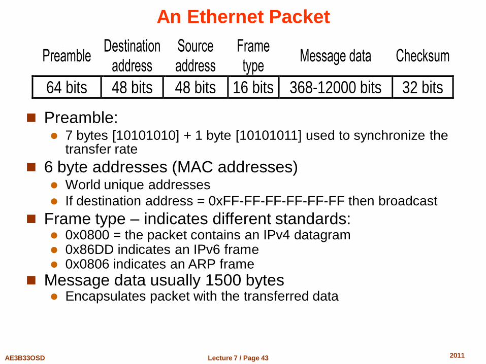
An Ethernet Packet
Preamble Destination
address Source address
Frame type
Message data Checksum
64 bits 48 bits 48 bits 16 bits 368-12000 bits 32 bits
Preamble:
7 bytes [10101010] + 1 byte [10101011] used to synchronize the transfer rate
6 byte addresses (MAC addresses) World unique addresses
If destination address = 0xFF-FF-FF-FF-FF-FF then broadcast
Frame type – indicates different standards: 0x0800 = the packet contains an IPv4 datagram 0x86DD indicates an IPv6 frame 0x0806 indicates an ARP frame
Message data usually 1500 bytes Encapsulates packet with the transferred data
Lecture 7 / Page 44 AE3B33OSD 2011
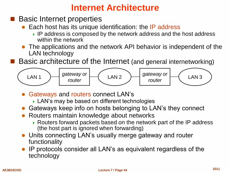
Internet Architecture
Basic Internet properties Each host has its unique identification: the IP address
IP address is composed by the network address and the host address within the network
The applications and the network API behavior is independent of the LAN technology
Basic architecture of the Internet (and general internetworking)
Gateways and routers connect LAN’s
LAN’s may be based on different technologies
Gateways keep info on hosts belonging to LAN’s they connect Routers maintain knowledge about networks
Routers forward packets based on the network part of the IP address (the host part is ignored when forwarding)
Units connecting LAN’s usually merge gateway and router functionality
IP protocols consider all LAN’s as equivalent regardless of the technology
LAN 1 LAN 2 LAN 3 gateway or
router
gateway or
router
Lecture 7 / Page 45 AE3B33OSD 2011
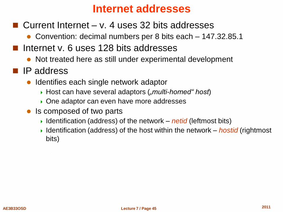
Internet addresses
Current Internet – v. 4 uses 32 bits addresses Convention: decimal numbers per 8 bits each – 147.32.85.1
Internet v. 6 uses 128 bits addresses Not treated here as still under experimental development
IP address Identifies each single network adaptor
Host can have several adaptors („multi-homed“ host)
One adaptor can even have more addresses
Is composed of two parts
Identification (address) of the network – netid (leftmost bits)
Identification (address) of the host within the network – hostid (rightmost
bits)
Lecture 7 / Page 46 AE3B33OSD 2011
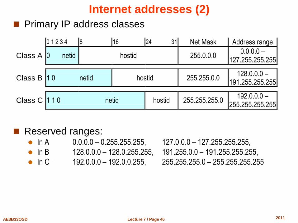
Internet addresses (2)
Primary IP address classes
Reserved ranges: In A 0.0.0.0 – 0.255.255.255, 127.0.0.0 – 127.255.255.255,
In B 128.0.0.0 – 128.0.255.255, 191.255.0.0 – 191.255.255.255,
In C 192.0.0.0 – 192.0.0.255, 255.255.255.0 – 255.255.255.255
0 1 2 3 4 8 16 24 31 Net Mask Address range
Class A 0 netid hostid 255.0.0.0 0.0.0.0 –
127.255.255.255
Class B 1 0 netid hostid 255.255.0.0 128.0.0.0 –
191.255.255.255
Class C 1 1 0 netid hostid 255.255.255.0 192.0.0.0 –
255.255.255.255
Lecture 7 / Page 47 AE3B33OSD 2011
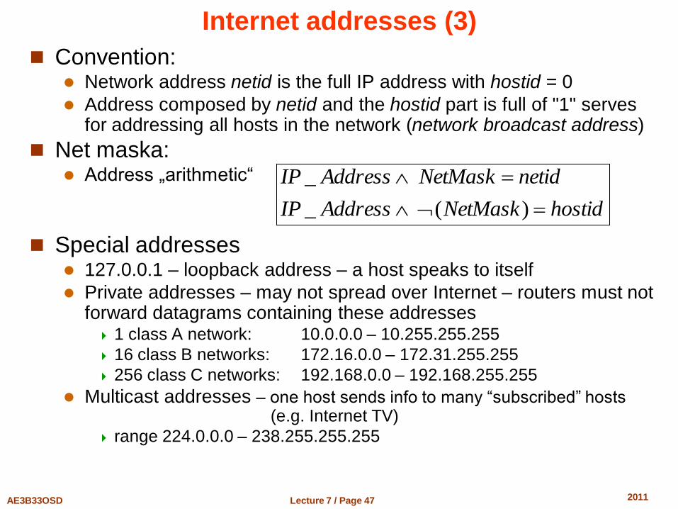
Internet addresses (3)
Convention: Network address netid is the full IP address with hostid = 0
Address composed by netid and the hostid part is full of "1" serves for addressing all hosts in the network (network broadcast address)
Net maska: Address „arithmetic“
Special addresses 127.0.0.1 – loopback address – a host speaks to itself
Private addresses – may not spread over Internet – routers must not forward datagrams containing these addresses 1 class A network: 10.0.0.0 – 10.255.255.255
16 class B networks: 172.16.0.0 – 172.31.255.255
256 class C networks: 192.168.0.0 – 192.168.255.255
Multicast addresses – one host sends info to many “subscribed” hosts (e.g. Internet TV)
range 224.0.0.0 – 238.255.255.255
hostidNetMaskAddressIP
netidNetMaskAddressIP
)(_
_
Lecture 7 / Page 48 AE3B33OSD 2011
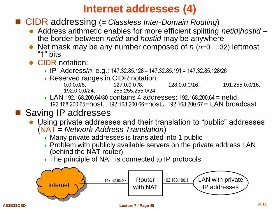
Internet addresses (4) CIDR addressing (= Classless Inter-Domain Routing)
Address arithmetic enables for more efficient splitting netid|hostid – the border between netid and hostid may be anywhere
Net mask may be any number composed of n (n=0 ... 32) leftmost “1” bits
CIDR notation: IP_Address/n; e.g.: 147.32.85.128 – 147.32.85.191 = 147.32.85.128/26
Reserved ranges in CIDR notation: 0.0.0.0/8, 127.0.0.0 /8, 128.0.0.0/16, 191.255.0.0/16, 192.0.0.0/24, 255.255.255.0/24
LAN 192.168.200.64/30 contains 4 addresses: 192.168.200.64 = netid, 192.168.200.65=host1, 192.168.200.66=host2, 192.168.200.67 = LAN broadcast
Saving IP addresses Using private addresses and their translation to “public” addresses
(NAT = Network Address Translation) Many private addresses is translated into 1 public Problem with publicly available servers on the private address LAN
(behind the NAT router) The principle of NAT is connected to IP protocols
Internet LAN with private
IP addresses Router
with NAT 147.32.85.27 192.168.100.1
Lecture 7 / Page 49 AE3B33OSD 2011
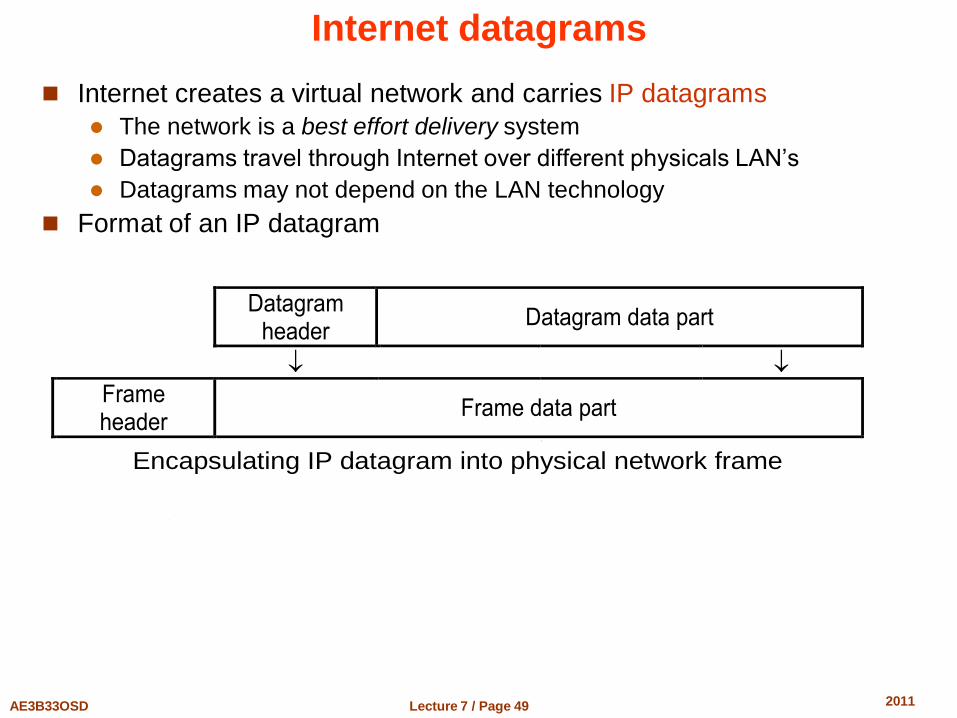
Internet datagrams
Internet creates a virtual network and carries IP datagrams
The network is a best effort delivery system
Datagrams travel through Internet over different physicals LAN’s
Datagrams may not depend on the LAN technology
Format of an IP datagram
Datagram
header Datagram data part
Frame header
Frame data part
Encapsulating IP datagram into physical network frame
Lecture 7 / Page 50 AE3B33OSD 2011
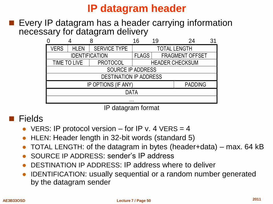
IP datagram header
Every IP datagram has a header carrying information necessary for datagram delivery
Fields VERS: IP protocol version – for IP v. 4 VERS = 4
HLEN: Header length in 32-bit words (standard 5)
TOTAL LENGTH: of the datagram in bytes (header+data) – max. 64 kB
SOURCE IP ADDRESS: sender’s IP address
DESTINATION IP ADDRESS: IP address where to deliver
IDENTIFICATION: usually sequential or a random number generated by the datagram sender
0 4 8 16 19 24 31
VERS HLEN SERVICE TYPE TOTAL LENGTH
IDENTIFICATION FLAGS FRAGMENT OFFSET
TIME TO LIVE PROTOCOL HEADER CHECKSUM
SOURCE IP ADDRESS
DESTINATION IP ADDRESS
IP OPTIONS (IF ANY) PADDING
DATA
…
IP datagram format
Lecture 7 / Page 51 AE3B33OSD 2011
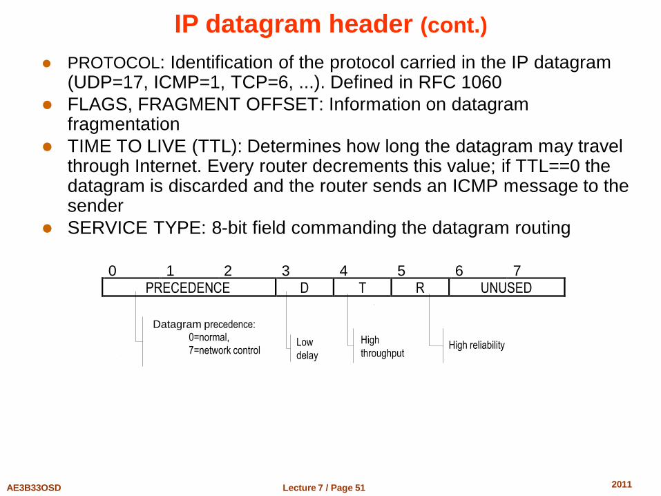
IP datagram header (cont.)
PROTOCOL: Identification of the protocol carried in the IP datagram (UDP=17, ICMP=1, TCP=6, ...). Defined in RFC 1060
FLAGS, FRAGMENT OFFSET: Information on datagram fragmentation
TIME TO LIVE (TTL): Determines how long the datagram may travel through Internet. Every router decrements this value; if TTL==0 the datagram is discarded and the router sends an ICMP message to the sender
SERVICE TYPE: 8-bit field commanding the datagram routing
0 1 2 3 4 5 6 7 PRECEDENCE D T R UNUSED
Datagram precedence: 0=normal,
7=network control Low
delay
High
throughput High reliability
Lecture 7 / Page 52 AE3B33OSD 2011
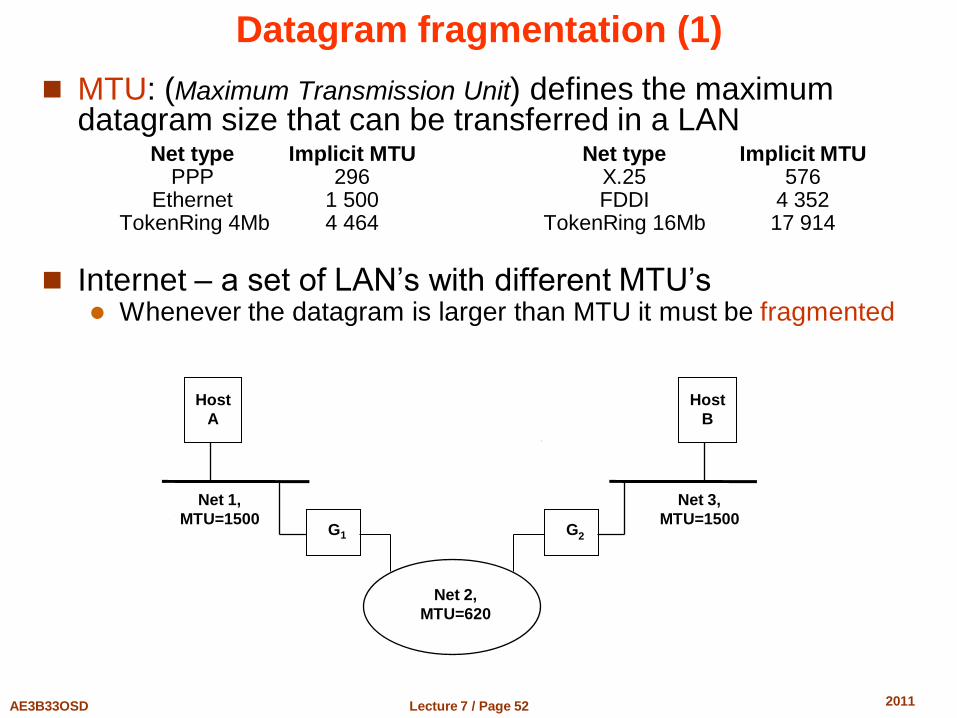
Datagram fragmentation (1)
MTU: (Maximum Transmission Unit) defines the maximum datagram size that can be transferred in a LAN Net type Implicit MTU Net type Implicit MTU PPP 296 X.25 576 Ethernet 1 500 FDDI 4 352 TokenRing 4Mb 4 464 TokenRing 16Mb 17 914
Internet – a set of LAN’s with different MTU’s Whenever the datagram is larger than MTU it must be fragmented
Host
B
Net 3,
MTU=1500
Host
A
Net 1,
MTU=1500
Net 2,
MTU=620
G 1 G 2
Lecture 7 / Page 53 AE3B33OSD 2011
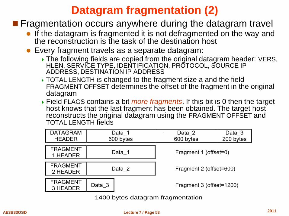
Datagram fragmentation (2) Fragmentation occurs anywhere during the datagram travel
If the datagram is fragmented it is not defragmented on the way and the reconstruction is the task of the destination host
Every fragment travels as a separate datagram: The following fields are copied from the original datagram header: VERS,
HLEN, SERVICE TYPE, IDENTIFICATION, PROTOCOL, SOURCE IP ADDRESS, DESTINATION IP ADDRESS
TOTAL LENGTH is changed to the fragment size a and the field FRAGMENT OFFSET determines the offset of the fragment in the original datagram
Field FLAGS contains a bit more fragments. If this bit is 0 then the target host knows that the last fragment has been obtained. The target host reconstructs the original datagram using the FRAGMENT OFFSET and TOTAL LENGTH fields
DATAGRAM HEADER
Data_1 600 bytes
Data_2 600 bytes
Data_3 200 bytes
FRAGMENT 1 HEADER
Data_1 Fragment 1 (offset=0)
FRAGMENT 2 HEADER
Data_2 Fragment 2 (offset=600)
FRAGMENT 3 HEADER
Data_3 Fragment 3 (offset=1200)
1400 bytes datagram fragmentation
Lecture 7 / Page 54 AE3B33OSD 2011
UDP Protocol
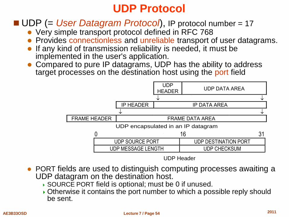
UDP (= User Datagram Protocol), IP protocol number = 17 Very simple transport protocol defined in RFC 768 Provides connectionless and unreliable transport of user datagrams. If any kind of transmission reliability is needed, it must be
implemented in the user's application. Compared to pure IP datagrams, UDP has the ability to address
target processes on the destination host using the port field
UDP HEADER
UDP DATA AREA
IP HEADER IP DATA AREA
FRAME HEADER FRAME DATA AREA
UDP encapsulated in an IP datagram
0 16 31 UDP SOURCE PORT UDP DESTINATION PORT
UDP MESSAGE LENGTH UDP CHECKSUM
UDP Header
PORT fields are used to distinguish computing processes awaiting a
UDP datagram on the destination host. SOURCE PORT field is optional; must be 0 if unused. Otherwise it contains the port number to which a possible reply should
be sent.
Lecture 7 / Page 55 AE3B33OSD 2011
UDP Protocol (cont.)
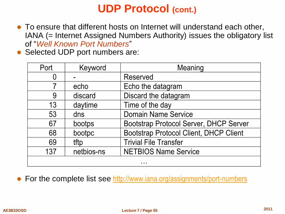
To ensure that different hosts on Internet will understand each other, IANA (= Internet Assigned Numbers Authority) issues the obligatory list of “Well Known Port Numbers”
Selected UDP port numbers are:
For the complete list see http://www.iana.org/assignments/port-numbers
Port Keyword Meaning
0 - Reserved
7 echo Echo the datagram
9 discard Discard the datagram
13 daytime Time of the day
53 dns Domain Name Service
67 bootps Bootstrap Protocol Server, DHCP Server
68 bootpc Bootstrap Protocol Client, DHCP Client
69 tftp Trivial File Transfer
137 netbios-ns NETBIOS Name Service
…
Lecture 7 / Page 56 AE3B33OSD 2011
TCP Protocol for reliable data streaming TCP is the most important general reliable transport service
providing a virtual bidirectional communication channel between two hosts TCP/IP is the IP implementation of this service
TCP properties Data stream
Applications communicating through a TCP connection consider the communication channel as a byte stream similarly to a file
Virtual connection Before the data transmission can start, the communicating applications have to negotiate the connection by means of the network components of their local operating systems – create and connect the sockets.
The protocol software (transport layer) in the operating systems of both hosts make an agreement on the connection using messages passed over the network. The hosts also verify that the connection can be reliably established and that both end-point systems are ready to communicate – open the sockets.
Afterwards the end-point applications are informed about the established connection and the data communication can start.
If the connection breaks, both communicating applications are informed The term virtual connection is used to create an illusion that applications are interconnected through a dedicated line.
The reliability is ensured by full hand-shake communication (everything must be acknowledged by the other party)
Lecture 7 / Page 57 AE3B33OSD 2011
TCP/IP – TCP Protocol IP Implementation
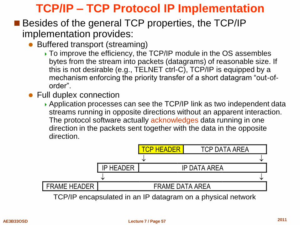
Besides of the general TCP properties, the TCP/IP implementation provides: Buffered transport (streaming)
To improve the efficiency, the TCP/IP module in the OS assembles bytes from the stream into packets (datagrams) of reasonable size. If this is not desirable (e.g., TELNET ctrl-C), TCP/IP is equipped by a mechanism enforcing the priority transfer of a short datagram “out-of-order”.
Full duplex connection Application processes can see the TCP/IP link as two independent data
streams running in opposite directions without an apparent interaction. The protocol software actually acknowledges data running in one direction in the packets sent together with the data in the opposite direction.
TCP HEADER TCP DATA AREA
IP HEADER IP DATA AREA
FRAME HEADER FRAME DATA AREA
TCP/IP encapsulated in an IP datagram on a physical network
Lecture 7 / Page 58 AE3B33OSD 2011
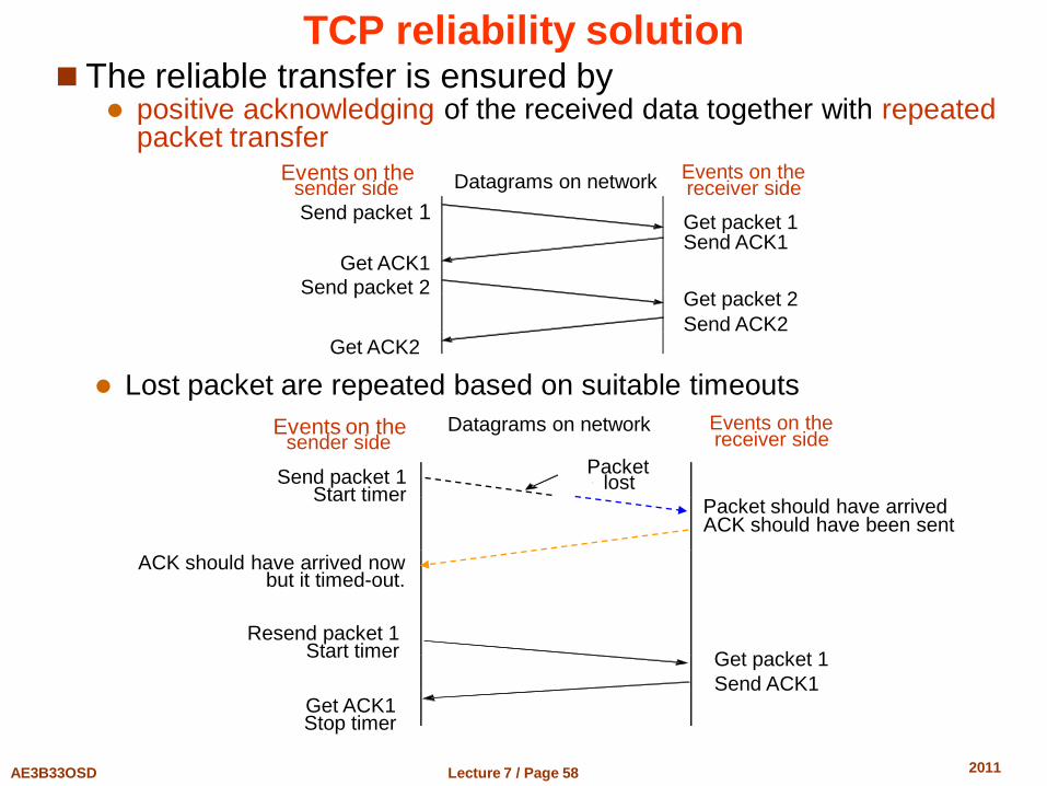
TCP reliability solution The reliable transfer is ensured by
positive acknowledging of the received data together with repeated packet transfer
Events on the sender side
Events on the receiver side Datagrams on network
Send packet 1 Get packet 1 Send ACK1
Get ACK1
Send packet 2 Get packet 2
Send ACK2 Get ACK2
Lost packet are repeated based on suitable timeouts
Packet should have arrived ACK should have been sent
Get packet 1
Send ACK1
Send packet 1 Start timer
ACK should have arrived now but it timed-out.
Resend packet 1 Start timer
Get ACK1 Stop timer
Events on the sender side
Events on the receiver side
Datagrams on network
Packet lost
Lecture 7 / Page 59 AE3B33OSD 2011
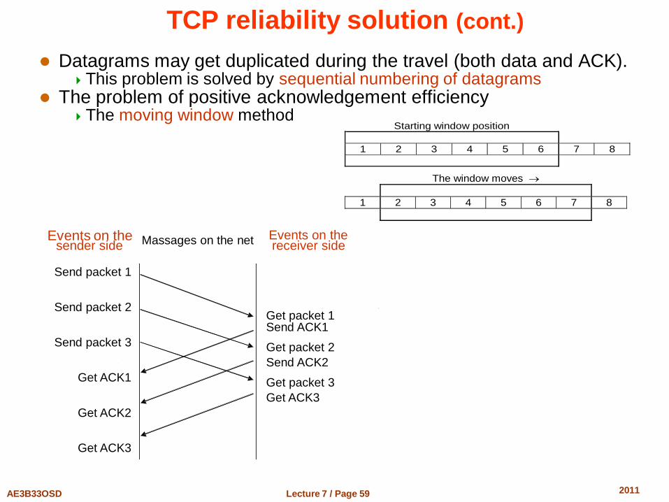
TCP reliability solution (cont.)
Datagrams may get duplicated during the travel (both data and ACK). This problem is solved by sequential numbering of datagrams
The problem of positive acknowledgement efficiency The moving window method
Starting window position
1 2 3 4 5 6 7 8
The window moves
1 2 3 4 5 6 7 8
Massages on the net
Send packet 1
Send packet 2
Send packet 3
Get ACK1
Get ACK2
Get ACK3
Get packet 1 Send ACK1
Get packet 2
Send ACK2
Get packet 3
Get ACK3
Events on the sender side
Events on the receiver side
Lecture 7 / Page 60 AE3B33OSD 2011
Retransmission timeouts
Constant value of timeout when to resend the TCP/IP segment is inappropriate Internet is too heterogeneous and is composed of a huge number of
LAN’s based on different HW technologies Giga-bit ethernet, 33 kbit serial line, intercontinental satellite link, etc.
TCP/IP adapts to changing timing parameters of the virtual connection A simple adaptive algorithm to adjust the timeout is used
The algorithm is based on continuous monitoring of „round trip time“ (RTT)
Time between dispatching the packet and its acknowledgement.
The real timeout is then computed as a weighted average of RTT measured in the recent history.
This strategy quickly accommodates to the speed and load changes on the intermediate networks and routers
Lecture 7 / Page 61 AE3B33OSD 2011
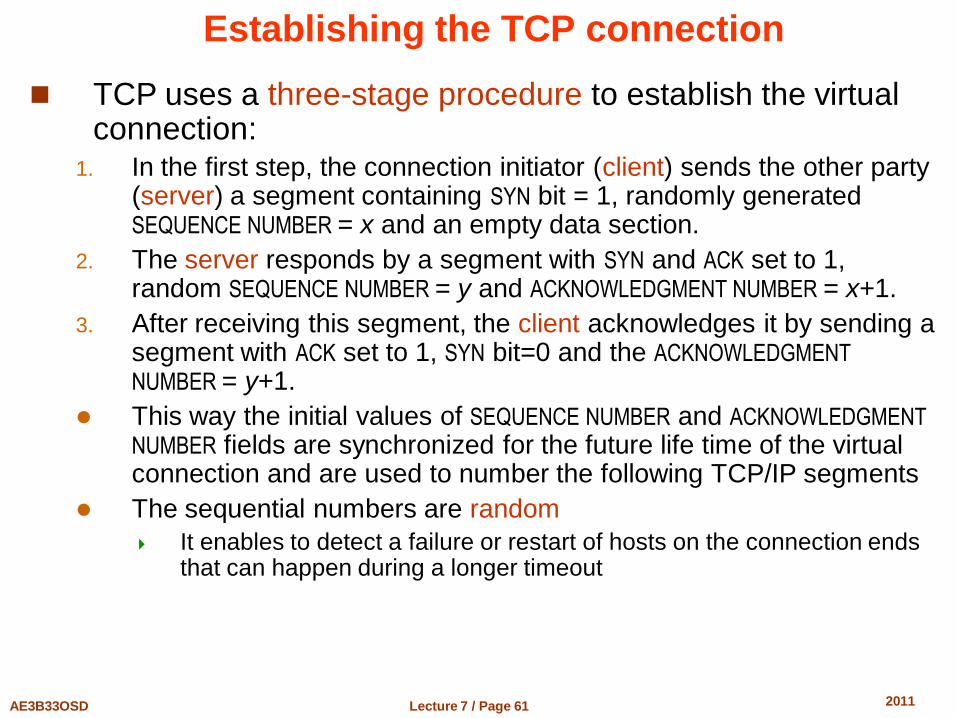
Establishing the TCP connection
TCP uses a three-stage procedure to establish the virtual connection:
1. In the first step, the connection initiator (client) sends the other party (server) a segment containing SYN bit = 1, randomly generated SEQUENCE NUMBER = x and an empty data section.
2. The server responds by a segment with SYN and ACK set to 1, random SEQUENCE NUMBER = y and ACKNOWLEDGMENT NUMBER = x+1.
3. After receiving this segment, the client acknowledges it by sending a segment with ACK set to 1, SYN bit=0 and the ACKNOWLEDGMENT
NUMBER = y+1.
This way the initial values of SEQUENCE NUMBER and ACKNOWLEDGMENT
NUMBER fields are synchronized for the future life time of the virtual connection and are used to number the following TCP/IP segments
The sequential numbers are random
It enables to detect a failure or restart of hosts on the connection ends that can happen during a longer timeout
Lecture 7 / Page 62 AE3B33OSD 2011
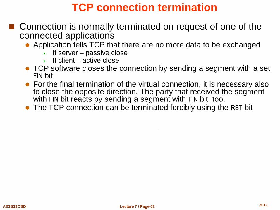
TCP connection termination
Connection is normally terminated on request of one of the connected applications Application tells TCP that there are no more data to be exchanged
If server – passive close If client – active close
TCP software closes the connection by sending a segment with a set FIN bit
For the final termination of the virtual connection, it is necessary also to close the opposite direction. The party that received the segment with FIN bit reacts by sending a segment with FIN bit, too.
The TCP connection can be terminated forcibly using the RST bit
Lecture 7 / Page 63 AE3B33OSD 2011
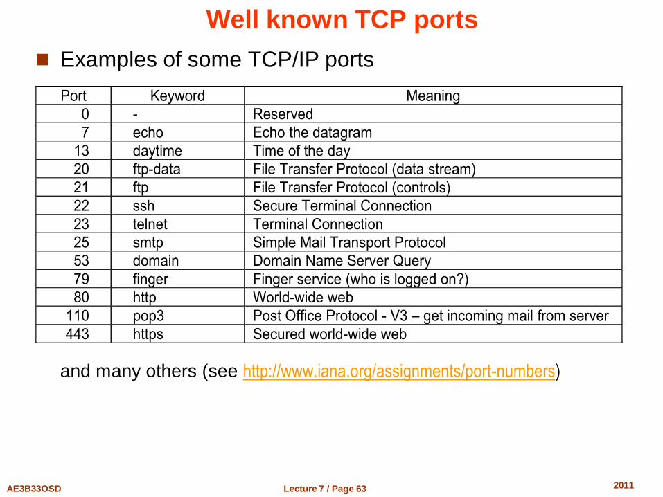
Well known TCP ports
Examples of some TCP/IP ports
and many others (see http://www.iana.org/assignments/port-numbers)
Port Keyword Meaning
0 - Reserved
7 echo Echo the datagram
13 daytime Time of the day
20 ftp-data File Transfer Protocol (data stream)
21 ftp File Transfer Protocol (controls)
22 ssh Secure Terminal Connection
23 telnet Terminal Connection
25 smtp Simple Mail Transport Protocol
53 domain Domain Name Server Query
79 finger Finger service (who is logged on?)
80 http World-wide web
110 pop3 Post Office Protocol - V3 – get incoming mail from server
443 https Secured world-wide web
Lecture 7 / Page 64 AE3B33OSD 2011
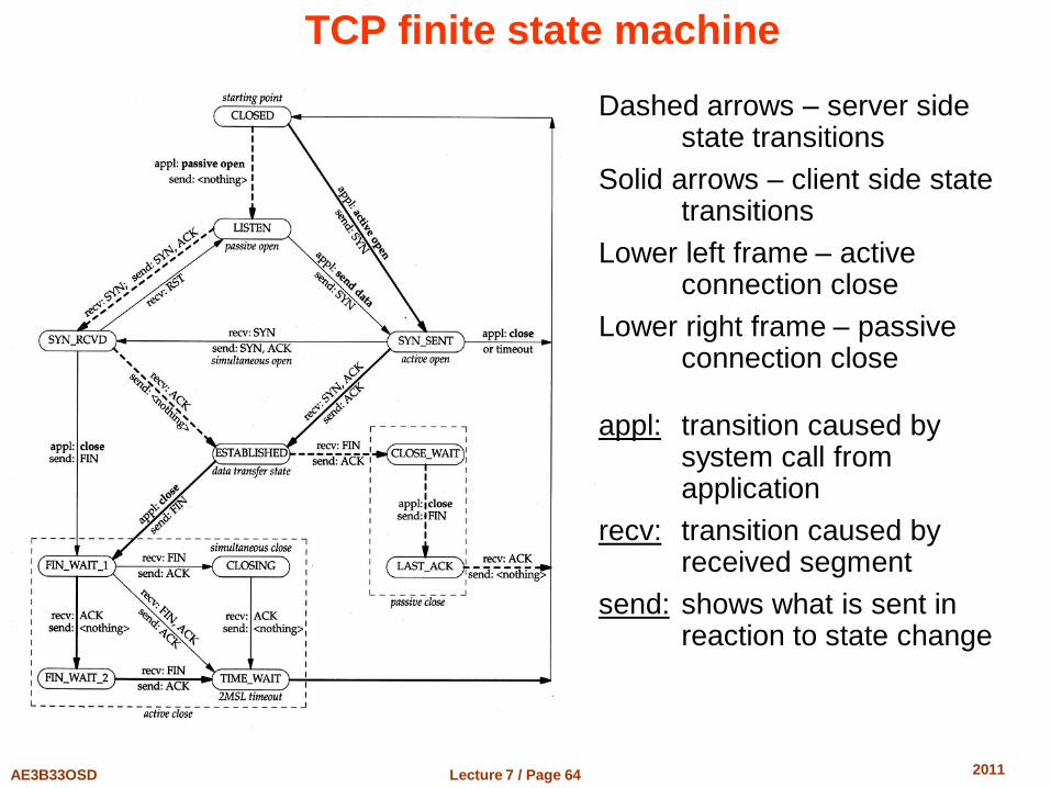
TCP finite state machine
Dashed arrows – server side state transitions
Solid arrows – client side state transitions
Lower left frame – active connection close
Lower right frame – passive connection close
appl: transition caused by system call from application
recv: transition caused by received segment
send: shows what is sent in reaction to state change

End of Lecture 7
Questions?