Lecture 615-441 © 2008 15-441 Lecture 6 Physical Layer (Cont) & Data Link Layer Based on slides...
66
Lecture 6 15-441 © 2008 15-441 Lecture 6 Physical Layer (Cont) & Data Link Layer Based on slides from previous 441 lectures 1
-
Upload
ashlyn-russell -
Category
Documents
-
view
214 -
download
0
Transcript of Lecture 615-441 © 2008 15-441 Lecture 6 Physical Layer (Cont) & Data Link Layer Based on slides...

Lecture 6 15-441 © 2008
15-441 Lecture 6
Physical Layer (Cont) &Data Link Layer
Based on slides from previous 441 lectures1
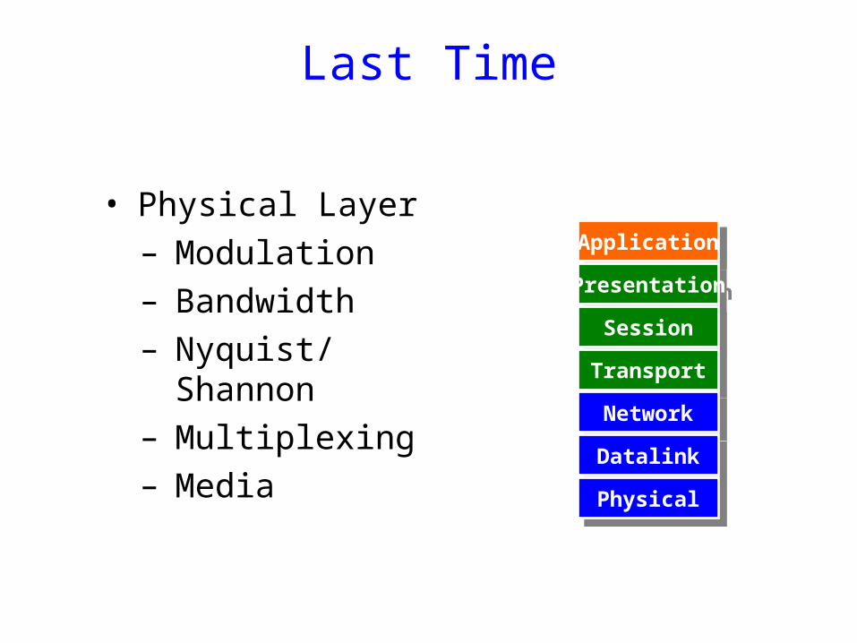
Last Time
• Physical Layer– Modulation– Bandwidth– Nyquist/Shannon– Multiplexing– Media
ApplicationApplication
PresentationPresentation
SessionSession
TransportTransport
NetworkNetwork
DatalinkDatalink
PhysicalPhysical

Today (& Tomorrow)
1.Physical layer.(Encoding)
2.Datalink layer introduction, framing, error coding, MAC, switched networks.
3.Broadcast-networks, home networking.
ApplicationApplication
PresentationPresentation
SessionSession
TransportTransport
NetworkNetwork
DatalinkDatalink
PhysicalPhysical
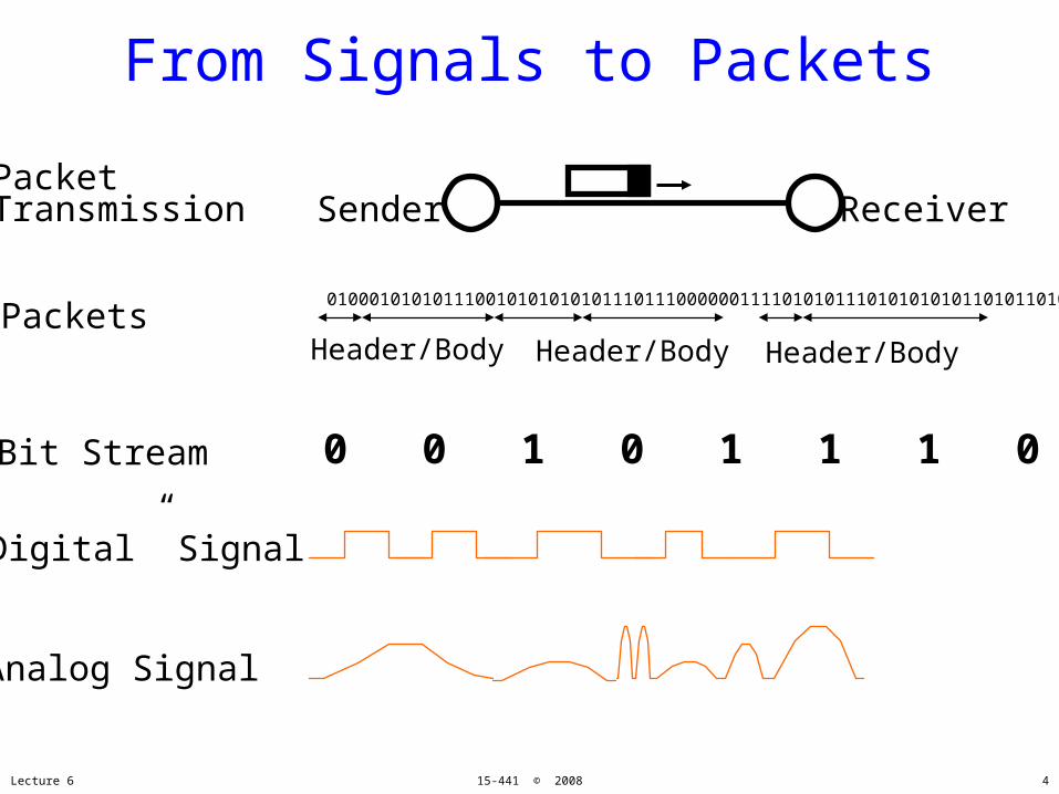
From Signals to Packets
Analog Signal
“Digital” Signal
Bit Stream 0 0 1 0 1 1 1 0 0 0 1
Packets0100010101011100101010101011101110000001111010101110101010101101011010111001
Header/Body Header/Body Header/Body
ReceiverSenderPacketTransmission
Lecture 6 15-441 © 2008 4
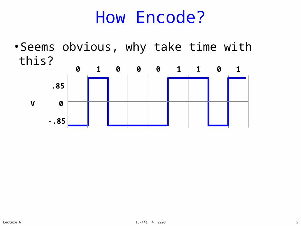
How Encode?
•Seems obvious, why take time with this?
Lecture 6 15-441 © 2008
V 0
.85
-.85
0 0 0 11 0 1 0 1
5

Why Encode?
Lecture 6 15-441 © 2008
0 1 0 1 How many more ones?
6
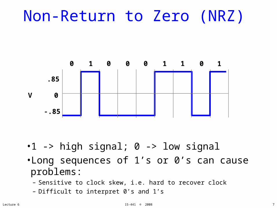
Non-Return to Zero (NRZ)
•1 -> high signal; 0 -> low signal•Long sequences of 1’s or 0’s can cause problems:– Sensitive to clock skew, i.e. hard to recover clock– Difficult to interpret 0’s and 1’s
V 0
.85
-.85
0 0 0 11 0 1 0 1
Lecture 6 15-441 © 2008 7
Why Do We Need Encoding?
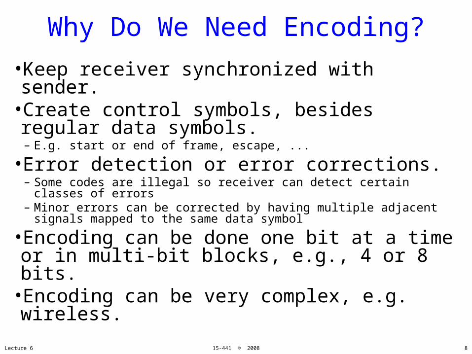
•Keep receiver synchronized with sender.•Create control symbols, besides regular data symbols.– E.g. start or end of frame, escape, ...
•Error detection or error corrections.– Some codes are illegal so receiver can detect certain classes of
errors– Minor errors can be corrected by having multiple adjacent
signals mapped to the same data symbol
•Encoding can be done one bit at a time or in multi-bit blocks, e.g., 4 or 8 bits.
•Encoding can be very complex, e.g. wireless.
Lecture 6 15-441 © 2008 8

Non-Return to Zero Inverted (NRZI)
•1 make transition; 0 signal stays the same
•Solves the problem for long sequences of 1’s, but not for 0’s.
V 0
.85
-.85
0 0 0 11 0 1 0 1
Lecture 6 15-441 © 2008 9

Ethernet Manchester Encoding
•Positive transition for 0, negative for 1•Transition every cycle communicates clock
V 0
.85
-.85
0 1 1 0
.1s
Lecture 6 15-441 © 2008 10
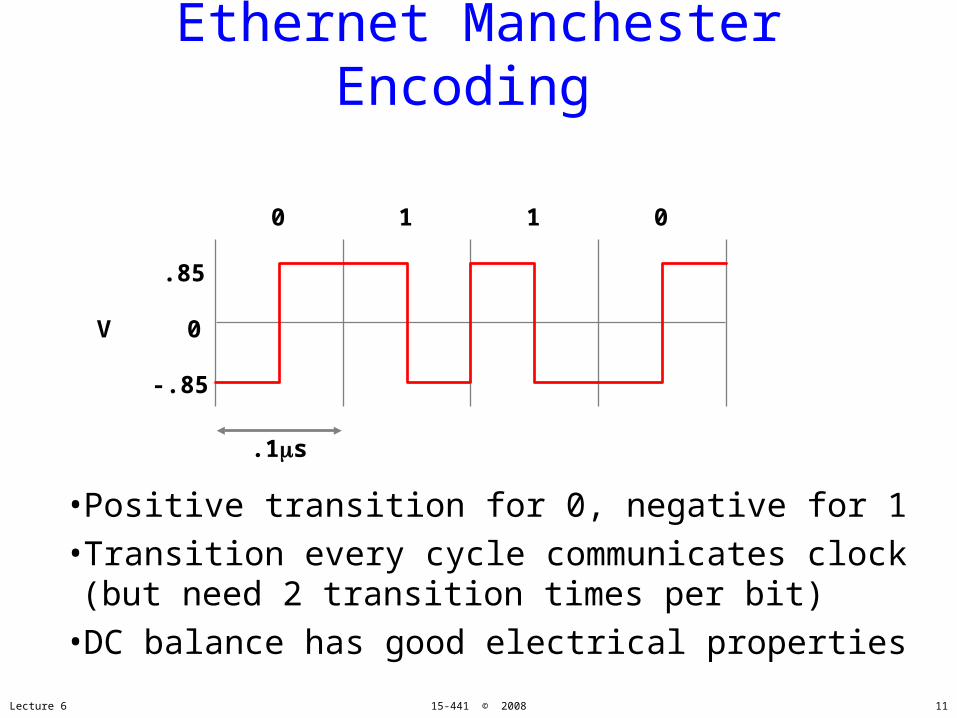
Ethernet Manchester Encoding
•Positive transition for 0, negative for 1•Transition every cycle communicates clock(but need 2 transition times per bit)
•DC balance has good electrical properties
V 0
.85
-.85
0 1 1 0
.1s
Lecture 6 15-441 © 2008 11

4B/5B Encoding
•Data coded as symbols of 5 line bits 4 data bits, so 100 Mbps uses 125
MHz.– Uses less frequency space than Manchester encoding
•Uses NRZI to encode the 5 code bits•Each valid symbol has at least two 1s
–So never get three 0s in a row– (Why don’t we care about 3 ones in a row?)
•16 data symbols, 8 control symbols – Data symbols: 4 data bits– Control symbols: idle, begin frame, etc.
•Example: FDDI.Lecture 6 15-441 © 2008 12

4B/5B Encoding
00000001001000110100010101100111
1111001001101001010101010010110111001111
Data Code
10001001101010111100110111101111
1001010011101101011111010110111110011101
Data Code
Lecture 6 15-441 © 2008 13

Other Encodings
•8B/10B: Fiber Channel and Gigabit Ethernet•64B/66B: 10 Gbit Ethernet•B8ZS: T1 signaling (bit stuffing)
•Encoding necessary for clocking•Lots of approaches•Rule of thumb:
–Little bandwidth complex encoding–Lots of bandwidth simple encoding
Lecture 6 15-441 © 2008
Things to Remember
14
Where we are
•We can send strings of bits•We can keep the transmitter and receiver clock synchronized
•What next?•Why?
Lecture 6 15-441 © 2008 15

Where we are
•We can send strings of bits•We can keep the transmitter and receiver clock synchronized
•What next?–Datalink layer
• Logical link control• Media access control
–Framing–Error detection/correction–Flow control–Access
Lecture 6 15-441 © 2008 16
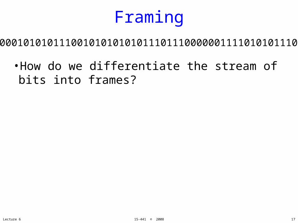
Framing
•How do we differentiate the stream of bits into frames?
Lecture 6 15-441 © 2008
0100010101011100101010101011101110000001111010101110101010101101011010111001
17

Framing•A link layer function, defining which bits have which function.
•Minimal functionality: mark the beginning and end of frames.
•Some techniques:– Out-of-band: delimiters (e.g. 4B/5B control
symbols)– In-band:
• frame delimiter characters with char stuffing• frame delimiter codes with bit stuffing
– Clock based: (e.g. SONET)
Lecture 6 15-441 © 2008 18
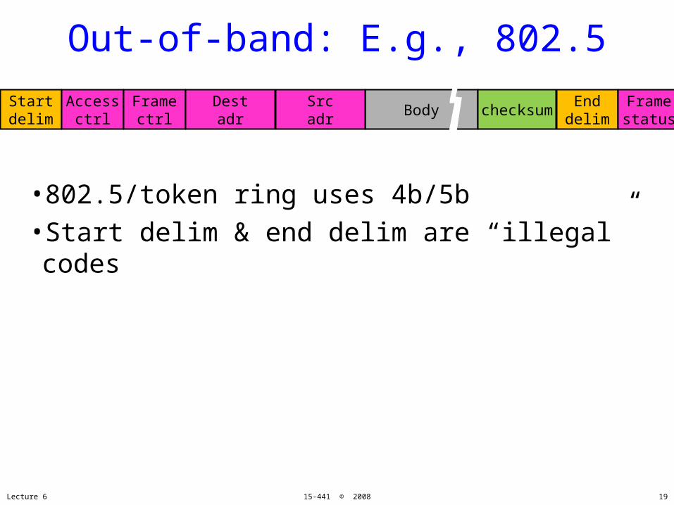
Out-of-band: E.g., 802.5
•802.5/token ring uses 4b/5b•Start delim & end delim are “illegal” codes
Lecture 6 15-441 © 2008
Startdelim
Accessctrl
Body checksumFramectrl
Destadr
Srcadr
Enddelim
Framestatus
19
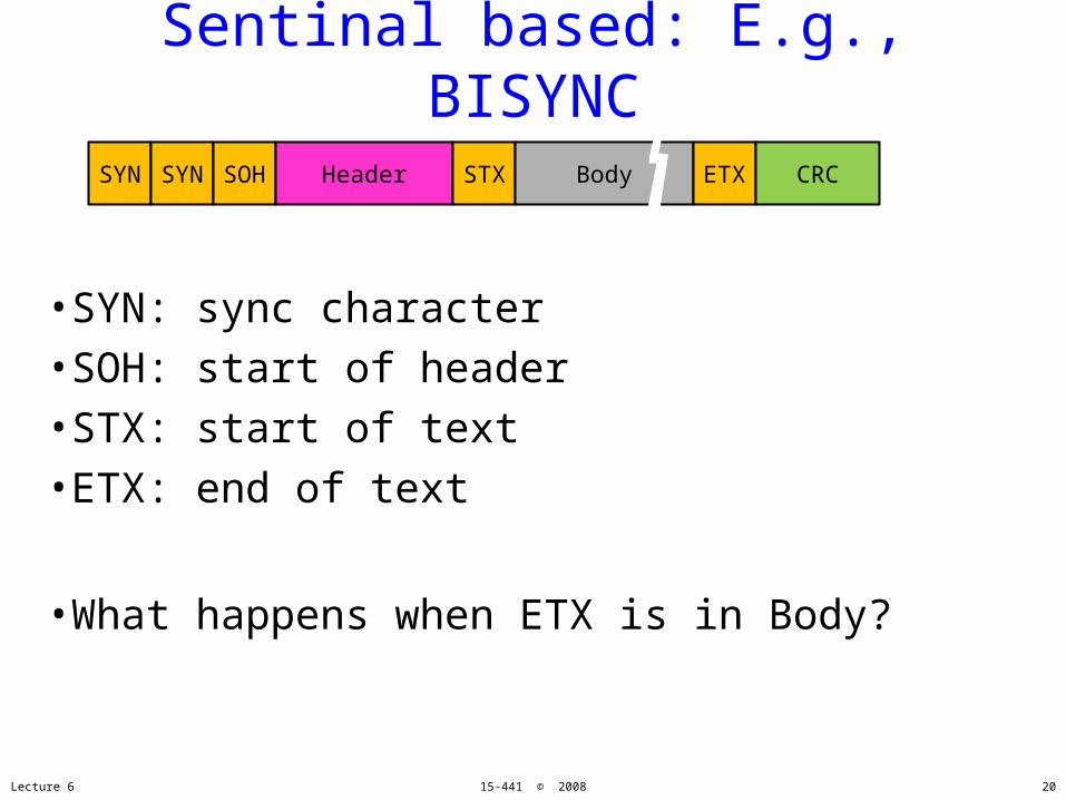
Sentinal based: E.g., BISYNC
•SYN: sync character•SOH: start of header•STX: start of text•ETX: end of text
•What happens when ETX is in Body?
Lecture 6 15-441 © 2008
SYN SYN SOH Header STX Body ETX CRC
20
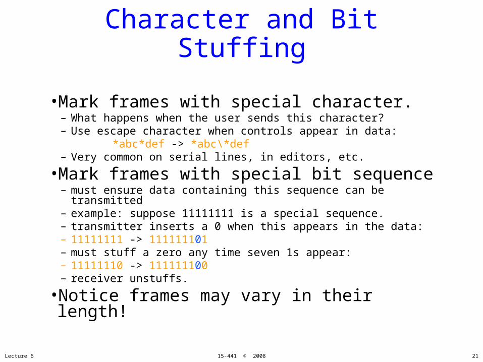
Character and Bit Stuffing
•Mark frames with special character.– What happens when the user sends this character?– Use escape character when controls appear in data: *abc*def -> *abc\*def– Very common on serial lines, in editors, etc.
•Mark frames with special bit sequence– must ensure data containing this sequence can be
transmitted– example: suppose 11111111 is a special sequence.– transmitter inserts a 0 when this appears in the data:– 11111111 -> 111111101– must stuff a zero any time seven 1s appear:– 11111110 -> 111111100– receiver unstuffs.
•Notice frames may vary in their length!
Lecture 6 15-441 © 2008 21

Ethernet Framing
•Preamble is 7 bytes of 10101010 (5 MHz square wave) followed by one byte of 10101011
•Allows receivers to recognize start of transmission after idle channel
preamblepreamble datagramdatagram lengthlength more stuffmore stuff
Lecture 6 15-441 © 2008 22

Clock Based Framing: SONET
•SONET is the Synchronous Optical Network standard for data transport over optical fiber.
•One of the design goals was to be backwards compatible with many older telco standards.
•Beside minimal framing functionality, it provides many other functions:– operation, administration and maintenance (OAM)
communications– synchronization– multiplexing of lower rate signals– multiplexing for higher rates
•In otherwords, really complicated!
Lecture 6 15-441 © 2008 23

Standardization History
•Process was started by divestiture in 1984.– Multiple telephone companies building their own infrastructure
•SONET concepts originally developed by Bellcore.
•First standardized by ANSI T1X1 group for US.•Later by CCITT and developed its own version.•SONET/SDH standards approved in 1988.
Lecture 6 15-441 © 2008 24
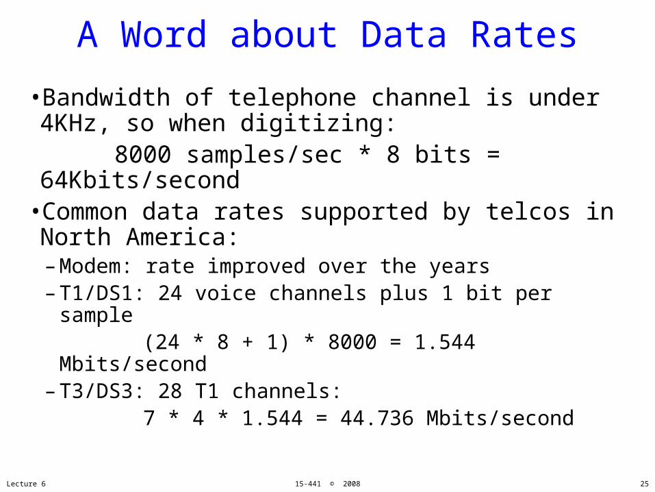
A Word about Data Rates
•Bandwidth of telephone channel is under 4KHz, so when digitizing:
8000 samples/sec * 8 bits = 64Kbits/second
•Common data rates supported by telcos inNorth America:– Modem: rate improved over the years– T1/DS1: 24 voice channels plus 1 bit per sample (24 * 8 + 1) * 8000 = 1.544 Mbits/second– T3/DS3: 28 T1 channels: 7 * 4 * 1.544 = 44.736 Mbits/second
Lecture 6 15-441 © 2008 25

Synchronous Data Transfer
•Sender and receiver are always synchronized.– Frame boundaries are recognized based on the clock– No need to continuously look for special bit sequences
•SONET frames contain room for control and data.– Data frame multiplexes bytes from many users– Control provides information on data, management, …
Lecture 6 15-441 © 2008
3 colstransportoverhead
87 cols payload capacity
9 rows
26

How avoid clock skew?
•Special bit sequences sent in first two chars of frame–But no bit stuffing. Hmmm?
•Lots of transitions by xoring with special pattern (and hope for the best)
Lecture 6 15-441 © 2008 27

SONET Framing
•Base channel is STS-1 (Synchronous Transport System).– Takes 125 sec and corresponds to 51.84 Mbps– 1 byte/frame corresponds to a 64 Kbs channel (voice)– Transmitted on an OC-1 optical carrier (fiber link)
•Standard ways of supporting slower and faster channels.– Support both old standards and future (higher) data rates
Lecture 6 15-441 © 2008
3 colstransportoverhead
87 cols payload capacity,including 1 col path overhead
9 rows
28
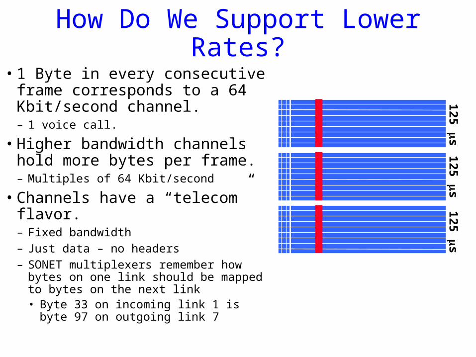
How Do We Support Lower Rates?
• 1 Byte in every consecutive frame corresponds to a 64 Kbit/second channel.– 1 voice call.
• Higher bandwidth channels hold more bytes per frame.– Multiples of 64 Kbit/second
• Channels have a “telecom” flavor.– Fixed bandwidth– Just data – no headers– SONET multiplexers remember how
bytes on one link should be mapped to bytes on the next link • Byte 33 on incoming link 1 is byte 97
on outgoing link 7
125 s
125 s
125 s

How Do We SupportHigher Rates?
• Send multiple frames in a 125 sec time slot.
• The properties of a channel using a single byte/ST-1 frame are maintained!– Constant 64 Kbit/second rate– Nice spacing of the byte samples
• Rates typically go up by a factor of 4.
• Two ways of doing interleaving.– Frame interleaving– Column interleaving
• concatenated version, i.e. OC-3c
125 s
125 s
125 s
STS-3chdr
125 s

The SONET Signal Hierarchy
Signal TypeSignal Type
OC-1OC-1
line rateline rate # of DS0# of DS0
51.84 Mbs51.84 Mbs 672672
OC-3OC-3 155 Mbs155 Mbs 2,0162,016
OC-12OC-12 622 Mbs622 Mbs 8,0648,064
STS-48STS-48 2.49 Gbs2.49 Gbs 32,25632,256
STS-192STS-192 9.95 Gbs9.95 Gbs 129,024129,024
STS-768STS-768 39.8 Gbs39.8 Gbs 516,096516,096
DS0 (POTS)DS0 (POTS) 64 Kbs64 Kbs 11
DS1DS1 1.544 Mbs1.544 Mbs 2424
DS3DS3 44.736 Mbs44.736 Mbs 672672STS-1 carriesone DS-3 plusoverhead
Lecture 6 15-441 © 2008 31

Using SONET in Networks
muxmux
muxmux
muxmux
DS1
OC-3c
OC-12c
OC-48
Add-drop capability allows soft configuration of networks,usually managed manually.
Lecture 6 15-441 © 2008 32
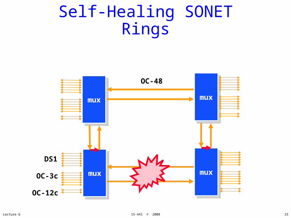
Self-Healing SONET Rings
muxmux muxmux
muxmux
DS1
OC-3c
OC-12c
OC-48
muxmux
Lecture 6 15-441 © 2008 33

SONET as Physical Layer
OC3/12Access
OC3/12Access
OC12/48Metro
OC3/12Access
OC3/12Access
OC12/48Metro
OC3/12Access
WDM BackboneOC48/192
OC12/48Metro
OC3/12Access
OC3/12Access
POP
POPPOP
CO CO
CO
CO
CO
CO
CO
Lecture 6 15-441 © 2008 34

Datalink Functions
•Framing: encapsulating a network layer datagram into a bit stream.– Add header, mark and detect frame boundaries, …
•Error control: error detection and correction to deal with bit errors.– May also include other reliability support, e.g. retransmission
•Flow control: avoid sender overrunning receiver.
•Media access: controlling which frame should be sent over the link next.– Easy for point-to-point links– Harder for multi-access links: who gets to send?
Lecture 6 15-441 © 2008 35

Error Coding
•Transmission process may introduce errors into a message.– Single bit errors versus burst errors
•Detection:– Requires a convention that some messages are invalid– Hence requires extra bits– An (n,k) code has codewords of n bits with k data bits and r =
(n-k) redundant check bits
•Correction– Forward error correction: many related code words map to
the same data word– Detect errors and retry transmission
Lecture 6 15-441 © 2008 36
Two basic approaches
•Forward Error Correction•Detect and Retransmit•Which should we use? Why? When?
Lecture 6 15-441 © 2008 37
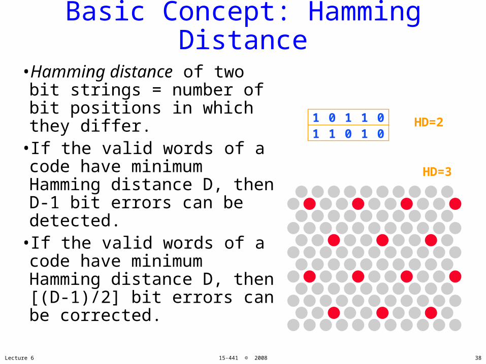
Basic Concept: Hamming Distance
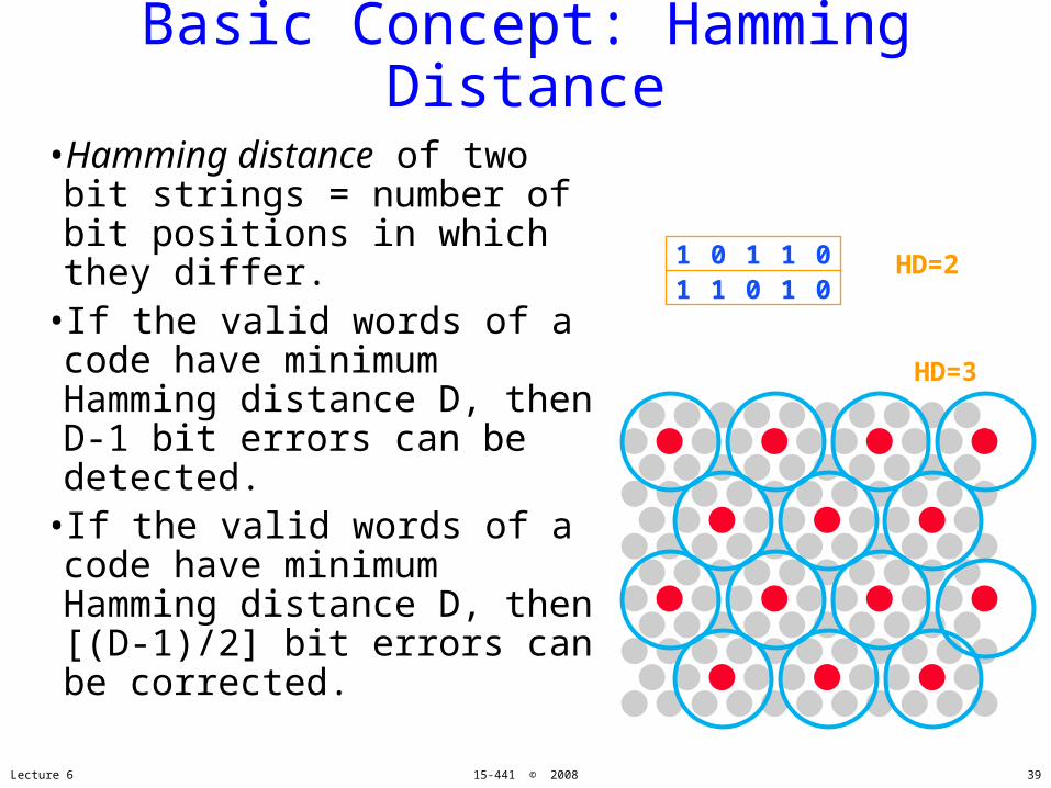
•Hamming distance of two bit strings = number of bit positions in which they differ.
•If the valid words of a code have minimum Hamming distance D, then D-1 bit errors can be detected.
•If the valid words of a code have minimum Hamming distance D, then [(D-1)/2] bit errors can be corrected.
Lecture 6 15-441 © 2008
1 0 1 1 01 1 0 1 0
HD=2
HD=3
38
Basic Concept: Hamming Distance
•Hamming distance of two bit strings = number of bit positions in which they differ.
•If the valid words of a code have minimum Hamming distance D, then D-1 bit errors can be detected.
•If the valid words of a code have minimum Hamming distance D, then [(D-1)/2] bit errors can be corrected.
Lecture 6 15-441 © 2008
1 0 1 1 01 1 0 1 0
HD=2
HD=3
39
Examples
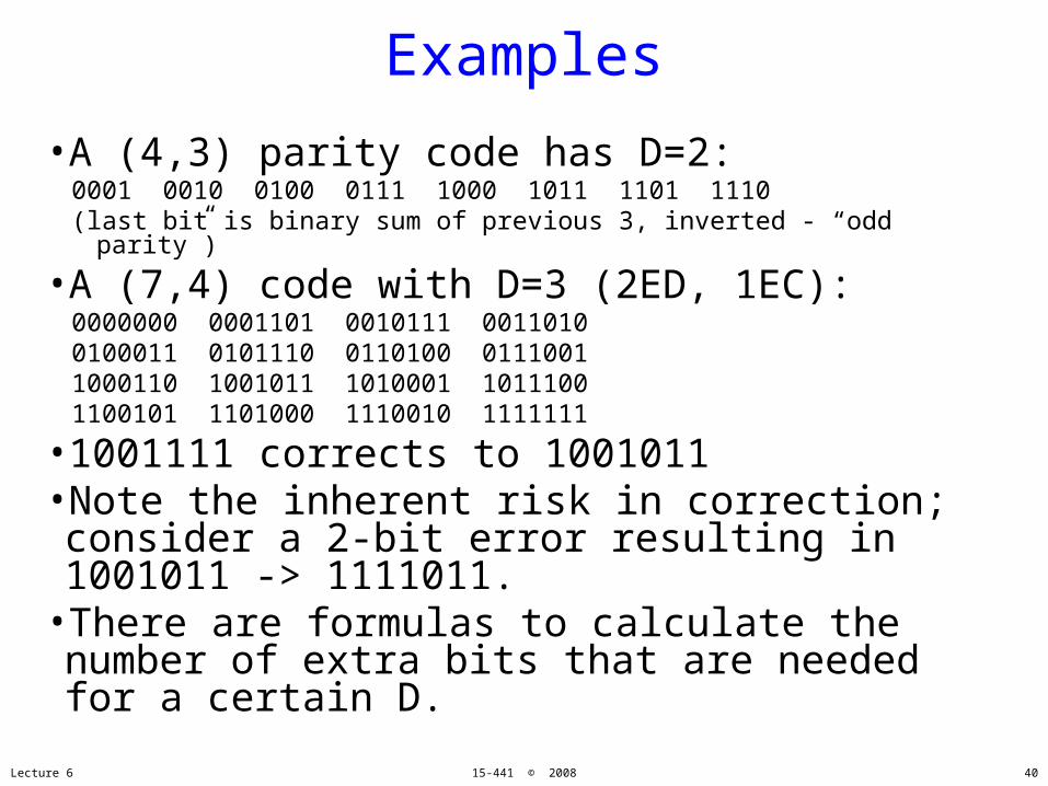
•A (4,3) parity code has D=2: 0001 0010 0100 0111 1000 1011 1101 1110(last bit is binary sum of previous 3, inverted - “odd parity”)
•A (7,4) code with D=3 (2ED, 1EC):0000000 0001101 0010111 0011010 0100011 0101110 0110100 01110011000110 1001011 1010001 1011100 1100101 1101000 1110010 1111111
•1001111 corrects to 1001011•Note the inherent risk in correction; consider a 2-bit error resulting in 1001011 -> 1111011.
•There are formulas to calculate the number of extra bits that are needed for a certain D.
Lecture 6 15-441 © 2008 40

Internet Checksum
•Add up all words transmitted(mod checksum size)
•Simple form of validation(and easy to implement)
Lecture 6 15-441 © 2008
Startdelim
Accessctrl
Body checksumFramectrl
Destadr
Srcadr
Enddelim
Framestatus
41
Cyclic Redundancy Codes(CRC)
•Commonly used codes that have good error detection properties.– Can catch many error combinations with a small
number or redundant bits•Based on division of polynomials.
– Errors can be viewed as adding terms to the polynomial
– Should be unlikely that the division will still work•Can be implemented very efficiently in hardware.
•Examples:– CRC-32: Ethernet– CRC-8, CRC-10, CRC-32: ATM
Lecture 6 15-441 © 2008 42

CRC: Basic idea•Treat bit strings as polynomials:
1 0 1 1 1X4+ X2+X1+X0
•Sender and Receiver agree on a divisor polynomialof degree k
•Message of M bits send M+k bits•No errors if M+k is divisible by divisor polynomial•If you pick the right divisor you can:
–Detect all 1 & 2-bit errors–Any odd number of errors–All Burst errors of less than k bits–Some burst errors >= k bits
Lecture 6 15-441 © 2008 43
Link Flow Control and Error Control
•Dealing with packet loss and corruption: error control.
•Dealing with receiver overflow: flow control.•Meta-comment: these issues are relevant at many layers.– Link layer: sender and receiver attached to the same “wire”– End-to-end: transmission control protocol (TCP) - sender and
receiver are the end points of a connection
•How can we implement flow control?
Lecture 6 15-441 © 2008 44

Link Flow Control and Error Control
•Dealing with packet loss and corruption: error control.
•Dealing with receiver overflow: flow control.•Meta-comment: these issues are relevant at many layers.– Link layer: sender and receiver attached to the same “wire”– End-to-end: transmission control protocol (TCP) - sender and
receiver are the end points of a connection
•How can we implement flow control?– “You may send” (windows, stop-and-wait, etc.)– “Please shut up” (source quench, 802.3x pause frames, etc.)– Where are each of these appropriate?
Lecture 6 15-441 © 2008 45

A Naïve Protocol
•Sender simply sends to the receiver whenever it has packets.
•Potential problem: sender can outrun the receiver.– Receiver too slow, buffer overflow, ..
•Not always a problem: receiver might be fast enough.
Sender Receiver
Lecture 6 15-441 © 2008 46
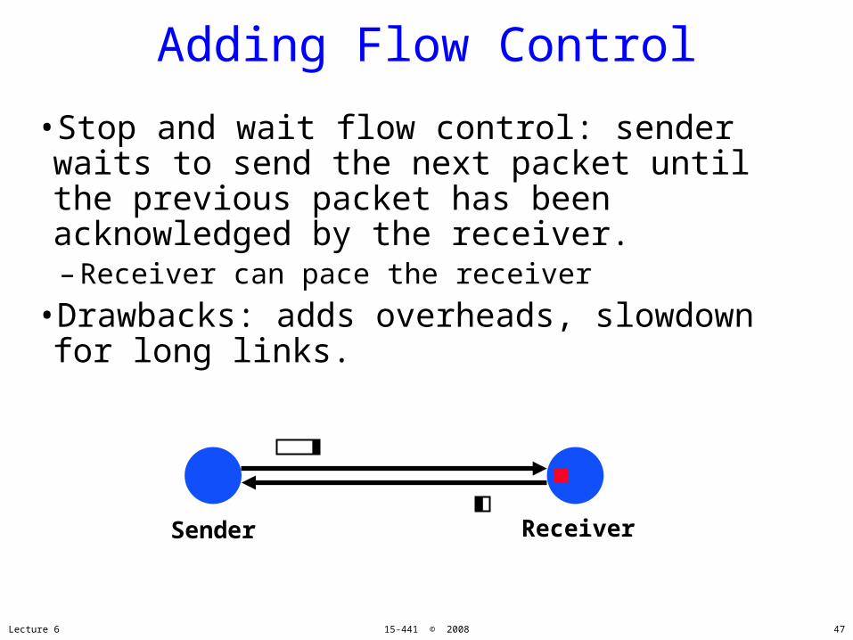
Adding Flow Control
•Stop and wait flow control: sender waits to send the next packet until the previous packet has been acknowledged by the receiver.– Receiver can pace the receiver
•Drawbacks: adds overheads, slowdown for long links.
Sender Receiver
Lecture 6 15-441 © 2008 47
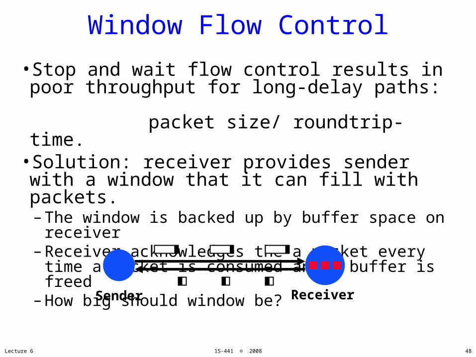
Window Flow Control
•Stop and wait flow control results in poor throughput for long-delay paths:
packet size/ roundtrip-time.•Solution: receiver provides sender with a window that it can fill with packets.– The window is backed up by buffer space on
receiver– Receiver acknowledges the a packet every time a
packet is consumed and a buffer is freed– How big should window be?
Sender Receiver
Lecture 6 15-441 © 2008 48

Bandwidth-Delay Product
Sender
Receiver
Time
Max Throughput = Window Size
Roundtrip Time
RTT
Lecture 6 15-441 © 2008 49

Dealing with ErrorsStop and Wait Case
•Packets can get lost, corrupted, or duplicated. – Error detection or correction turns corrupted packet in lost or
correct packet
•Duplicate packet: use sequence numbers.•Lost packet: time outs and acknowledgements.– Positive versus negative acknowledgements– Sender side versus receiver side timeouts
•Window based flow control: more aggressive use of sequence numbers (see transport lectures).
Sender Receiver
Lecture 6 15-441 © 2008 50
What is Used in Practice?
•No flow or error control.– E.g. regular Ethernet, just uses CRC for error
detection•Flow control only.
– E.g. Gigabit Ethernet•Flow and error control.
– E.g. X.25 (older connection-based service at 64 Kbs that guarantees reliable in order delivery of data)
Lecture 6 15-441 © 2008 51

So far …
Lecture 6 15-441 © 2008 52
•… But what if we want more nodes?
Wires for everybody!
Can connect two nodes

So far …
Lecture 6 15-441 © 2008 53
•… But what if we want more nodes?
Wires for everybody!
Can connect two nodes
P-2-p shared
switches

Datalink Architectures
• Point-Point with switches • Media access control.
Lecture 6 15-441 © 2008 54
Media Access Control
•How do we transfer packets between two hosts connected to the same network?
•Switches connected by point-to-point links -- store-and-forward.– Used in WAN, LAN, and for home connections– Conceptually similar to “routing”
• But at the datalink layer instead of the network layer
•Multiple access networks -- contention based.– Multiple hosts are sharing the same transmission medium– Used in LANs and wireless– Need to control access to the medium
Lecture 6 15-441 © 2008 55
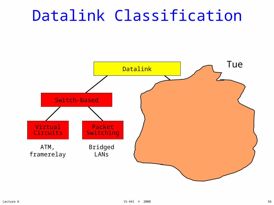
Datalink Classification
Datalink
Switch-based Multiple Access
RandomAccess
ScheduledAccess
PacketSwitching
VirtualCircuits
ATM,framerelay
Ethernet, 802.11, Aloha
Token ring,FDDI, 802.11
BridgedLANs
Lecture 6 15-441 © 2008 56
Tue

Switching
•Forward units of data based on address in header.
•Many data-link technologies use switching.– Virtual circuits: Frame Relay, ATM, X.25, ..– Packets: Ethernet, MPLS, …
•“Switching” also happens at the network layer.– Layer 3: Internet protocol– In this case, address is an IP address– IP over SONET, IP over ATM, ...– Otherwise, operation is very similar
•Switching is different from SONET mux/demux.– SONET channels statically configured - no addresses
Lecture 6 15-441 © 2008 57

A Switch-based Network
•Switches are connected by point-point links.•Packets are forwarded hop-by-hop by the switches towards the destination.– Forwarding is based on the address
•How does a switch work?•How do nodes exchange packets over a link?•How is the destination addressed?
Lecture 6 15-441 © 2008
PC atHome
SwitchPoint-Point
linkPCs atWork
58
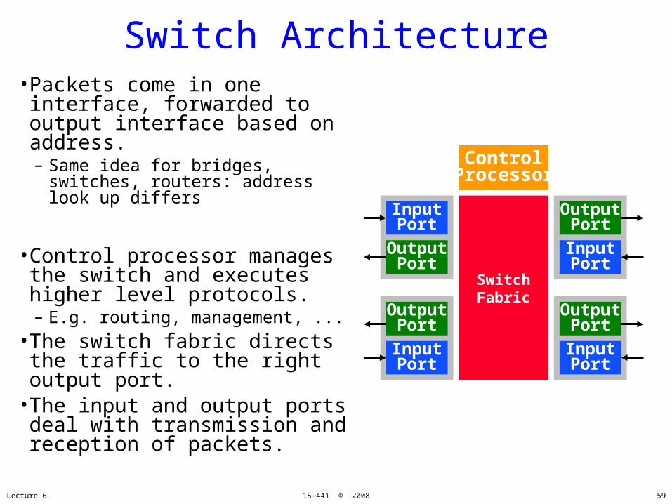
Switch Architecture•Packets come in one interface, forwarded to output interface based on address.– Same idea for bridges, switches,
routers: address look up differs
•Control processor manages the switch and executes higher level protocols.– E.g. routing, management, ...
•The switch fabric directs the traffic to the right output port.
•The input and output ports deal with transmission and reception of packets.
Lecture 6 15-441 © 2008
SwitchFabric
InputPort
OutputPort
OutputPort
InputPort
OutputPort
InputPort
OutputPort
InputPort
ControlProcessor
59

Connections or Not?
•Two basic approaches to packet forwarding–Connectionless–(virtual) Circuit switched
•When would you use?
Lecture 6 15-441 © 2008 60

•Host can send anytime anywhere•No idea if resources are available to get to dest
•Forwarding is independent for each packet•No setup time•Fault tolerant
Connectionless
Lecture 6 15-441 © 2008 61
Destination
Port
A 3
B 0
C
D
E
F
G
H

Virtual Circuit Switching
•Two stage process–Setup connection (create VCIs)–Send packets
•RTT introduced before any data is sent•Per packet overhead can be smaller (VCI << adr)
•Switch failures are hard to deal with•Reserves resources for connection
Lecture 6 15-441 © 2008 62

Setup, assign VCIs
Lecture 6 15-441 © 2008 63

Packet Forwarding:Address Lookup
• Address from header.– Absolute address (e.g. Ethernet)– (IP address for routers)– (VC identifier, e.g. ATM))
• Next hop: output port for packet.• Info: priority, VC id, ..• Table is filled in by protocol.
B31123812508 3
Switch
38913C3C2137 3
A21023C90590 0
128.2.15.3 1
Address Next Hop
13
-
-
(2,34)
Info

Datalink Classification
Datalink
Switch-based Multiple Access
RandomAccess
ScheduledAccess
PacketSwitching
VirtualCircuits
ATM,framerelay
Ethernet, 802.11, Aloha
Token ring,FDDI, 802.11
BridgedLANs
Lecture 6 15-441 © 2008 65
Tue
What we covered
•Encoding: way to put 1s and 0s on the line so receiver can decode them
•Framing: way to understand a basic chunk•Error Control: ensure packets are not corrupted
•Flow control: Ensure receiver doesn’t get overrun
•Media Access Control: How to get multiple nodes talking on the same network without requiring n2 wires.
Lecture 6 15-441 © 2008 66