Lecture 6 Block (Aerial) Triangulation....
16
NRMT 2270, Photogrammetry/Remote Sensing Lecture 6 Block (Aerial) Triangulation. Orthorectification. Tomislav Sapic GIS Technologist Faculty of Natural Resources Management Lakehead University
Transcript of Lecture 6 Block (Aerial) Triangulation....

NRMT 2270, Photogrammetry/Remote Sensing
Lecture 6
Block (Aerial) Triangulation. Orthorectification.
Tomislav SapicGIS Technologist
Faculty of Natural Resources ManagementLakehead University
Block (Aerial) Triangulation
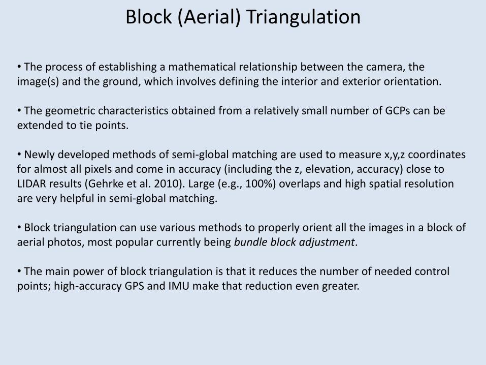
• The process of establishing a mathematical relationship between the camera, the image(s) and the ground, which involves defining the interior and exterior orientation.
• The geometric characteristics obtained from a relatively small number of GCPs can be extended to tie points.
• Newly developed methods of semi-global matching are used to measure x,y,z coordinates for almost all pixels and come in accuracy (including the z, elevation, accuracy) close to LIDAR results (Gehrke et al. 2010). Large (e.g., 100%) overlaps and high spatial resolution are very helpful in semi-global matching.
• Block triangulation can use various methods to properly orient all the images in a block of aerial photos, most popular currently being bundle block adjustment.
• The main power of block triangulation is that it reduces the number of needed control points; high-accuracy GPS and IMU make that reduction even greater.

• Information created through block triangulation is needed for:
o Orthorectification
o DEM creation
o Georeferenced stereo viewing (stereo viewing within a three-dimensional standard coordinate system representing the space on and around the surface of the Earth).
Block (Aerial) Triangulation

Bundle Block Adjustment• The most accurate and flexible method of block (aerial) triangulation currently in use.
• An image (photo) is considered as a bundle of rays – each image ray connects an object space point, the perspective centre of an image, and the projection of the point on the image. In the case of linear sensors, each line defines a new bundle, with its own six elements of exterior orientation (Mikhail et al. 2001).
• The bundle block adjustment establishes the position and orientation of each bundle, using the rays in each bundle and the given ground control information.
http://dprg.geomatics.ucalgary.ca/system/files/AKAM_531_PPT_CH1_h.pdf
Bundle Block Adjustment
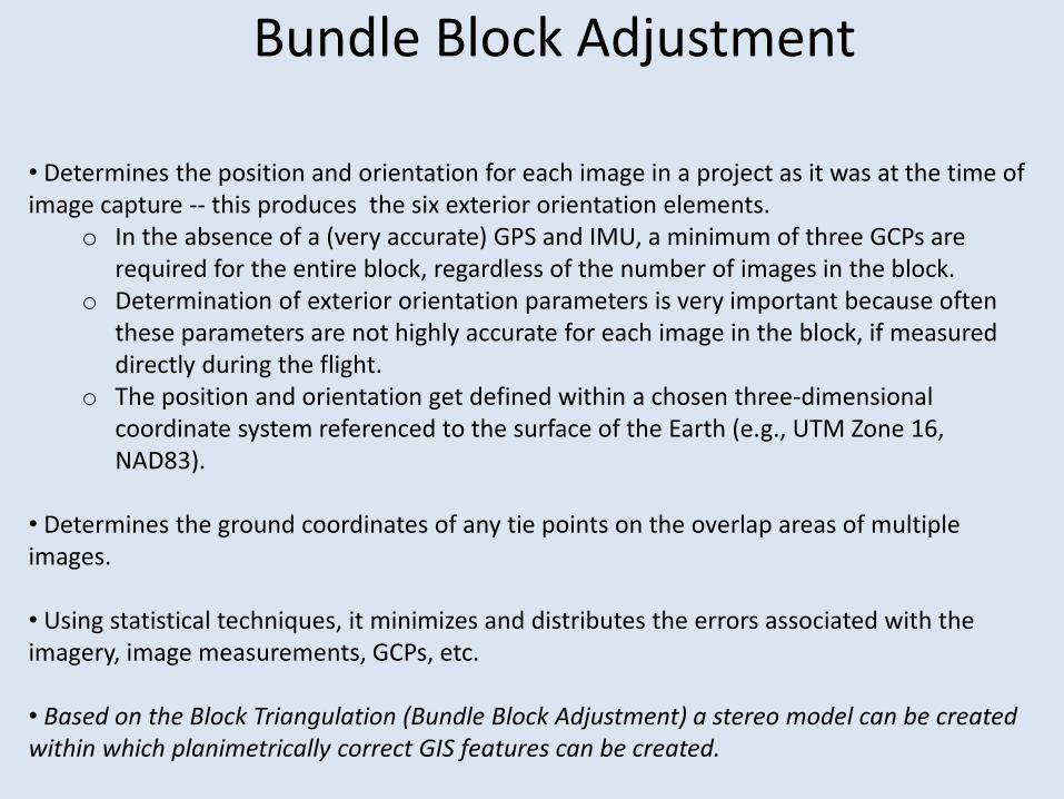
• Determines the position and orientation for each image in a project as it was at the time of image capture -- this produces the six exterior orientation elements.
o In the absence of a (very accurate) GPS and IMU, a minimum of three GCPs are required for the entire block, regardless of the number of images in the block.
o Determination of exterior orientation parameters is very important because often these parameters are not highly accurate for each image in the block, if measured directly during the flight.
o The position and orientation get defined within a chosen three-dimensional coordinate system referenced to the surface of the Earth (e.g., UTM Zone 16, NAD83).
• Determines the ground coordinates of any tie points on the overlap areas of multiple images.
• Using statistical techniques, it minimizes and distributes the errors associated with the imagery, image measurements, GCPs, etc.
• Based on the Block Triangulation (Bundle Block Adjustment) a stereo model can be created within which planimetrically correct GIS features can be created.

Creation of DEM/DSM • Block triangulation can be used to extract DEM/DSM.
DEM – Digital Elevation Model (bare ground surface or a generic term for both DTM and DSM)
DTM – Digital Terrain Model (bare ground surface)DSM – Digital Surface Model (the elevation of the top of the surface, i.e. ground, trees,
buildings).
DSM – buildings included DEM (DTM) – buildings removed
• Ontario eFRI imagery products include a classified DSM.Source: Jensen (2007)

Ontario eFRI ADS40 DSM for Lakehead U. Campus

Perspective Projection Orthographic Projection(points are projected orthogonalto a reference surface)
Source: Mikhail et al. (2001)
Perspective Projection – Orthographic Projection – Planimetric Photo/Plain
• Perspective projection produces relief displacement.• Orthographic projection removes relief displacement and produces a planimetric photo, from which planimetric features can be mapped. • Planimetric - of a map : having no indications of relief (Merriam-Webster Dictionary).

The Process of Reducing Geometric Errors Inherent in Aerial Imagery
• The variables that contribute to geometric errors include but are not limited to:o Camera and sensor orientationo Systematic errors associated with the camera or sensoro Earth curvatureo Topographic relief (radial) displacement
• Block triangulation minimizes and eliminates the first three errors, orthorectificationrectifies the fourth error.
• The result of orthorectification is an orthoimage.

Source: Mikhail et al. (2001)
•Orthophotos (orthoimages) are created by changing the geometry of the photo from that of a conical bundle of rays to parallel rays that are orthogonal to the ground and to the image plane.
• Relief displacement is removed, and through that, parallax is removed – ortho photos cannot be seen in stereo!
Orthorectification
• Orthophotos are planimetrically correct --each pixel within the image possesses geometric fidelity with respect to the corresponding ground measurements. The distance between points on an orthophotoequals, accounting for the photo scale, the horizontal distance between the corresponding points on the ground.

• A DEM (DTM) of the area is needed for orthorectification .
• The DEM is also used to separate the ground surface elevation from the non-ground (e.g., trees, buildings) surface elevation.
• If buildings are not included in the DEM, they are not orthorectified and remain ‘leaning’.
• The DEM (DSM) produced through block triangulation can also be used for orthorectification. A DSM does contain building heights, so that buildings get orthorectified as well – they don’t ‘lean’.
Orthorectification

Ontario eFRI ADS40 Orthoimage for Lakehead U. Campus
• The image is part of a tile cut out from an ADS40 ortho mosaic.

Ortho Mosaic• Frame orthophotos are often stitched together into ortho mosaics.

Extraction of Digital Elevation Models, Orthoimagery, and Planimetric Features Using Soft-copy Photogrammetry
Source: Jensen (2007)

Soft-copy Photogrammetry RecapWhen working with vertical, stereo, digital aerial photos (images) taken by a digital camera, in a photogrammetry software (such as Erdas):
1) Add the images to a block representing all or a subset of images taken during an aerial photogrammetry project.
2) Set the coordinate system (map projection) for the project, i.e. the coordinate system of the reference (GCP) points.
3) Set the camera specifications (e.g., model, lens distortion (if available)) and settings (e.g. focal length) and interior orientation parameters (pixel size).
4) Identify GCPs (e.g., UTM coordinates) and Tie Points across all involved images
If the images were taken with a system with highly accurate position (GPS) and orientation (IMU) measurements, GCPs and Tie Points may not be required – Leica ADS imagery does not require GCPs and Tie Points).
Provide elevations for GCPs as well (e.g., by extracting elevations from a DEM for GCP UTM coordinate positions).
5) Run Aerial Triangulation, namely the Bundle Block Adjustment method. If not previously defined, the six of Exterior Orientation elements are now defined for each photo.
6) The photos are now ready for viewing in stereo within the set coordinate system.
7) Optionally, extract planimetric features while viewing the photos in stereo.
8) Optionally, create the DSM for the area.
9) Optionally, create ortho-photos by using the DEM or DSM. Planimetric features can be extracted from ortho photos in a 2D (non-stereo) view.
10) Optionally, create an ortho mosaic for the area.

References:
Jensen., J. R. 2007. Remote Sensing of the Environment: An Earth Resource Perspective. Pearson Prentice Hall.
Mikhail M., J. S. Bethel, J. and C. McGlone. 2001. Introduction to Modern Photogrammetry. John Wiley & Sons.