Lecture 6 6 - NPTELnptel.ac.in/courses/103103033/module6/lecture6.pdf · Flotation is a process of...
20
NPTEL Chemical Engineering Interfacial Engineering Module 6: Lecture 6 Joint Initiative of IITs and IISc Funded by MHRD 1/20 Froth Flotation Dr. Pallab Ghosh Associate Professor Department of Chemical Engineering IIT Guwahati, Guwahati–781039 India
Transcript of Lecture 6 6 - NPTELnptel.ac.in/courses/103103033/module6/lecture6.pdf · Flotation is a process of...

NPTEL Chemical Engineering Interfacial Engineering Module 6: Lecture 6
Joint Initiative of IITs and IISc Funded by MHRD 1/20
Froth Flotation
Dr. Pallab Ghosh
Associate Professor
Department of Chemical Engineering
IIT Guwahati, Guwahati–781039
India

NPTEL Chemical Engineering Interfacial Engineering Module 6: Lecture 6
Joint Initiative of IITs and IISc Funded by MHRD 2/20
Table of Contents
Section/Subsection Page No. 6.6.1 Introduction 3
6.6.2 Flotation cells 5
6.6.3 Collectors, frothers, depressants, activators and deactivators 6
6.6.4 Role of intermolecular and surface forces 8
6.6.5 Flotation conditions 11
6.6.6 Flotation recovery 13
6.6.6.1 Probability of collision 13
6.6.6.2 Probability of attachment 14
6.6.6.3 Flotation recovery 15
6.6.7 Micro-processes in flotation 16
Exercise 19
Suggested reading 20

NPTEL Chemical Engineering Interfacial Engineering Module 6: Lecture 6
Joint Initiative of IITs and IISc Funded by MHRD 3/20
6.6.1 Introduction
Flotation is a process of separation and concentration based on differences in the
physicochemical properties of interfaces. Flotation can take place either at a liquid–gas, a
liquid–liquid, a liquid–solid or a solid–gas interface.
For example, oil flotation takes place on the interface between oil and water. Film
flotation takes place on a free water surface. In this flotation process, hydrophobic
particles float on the free surface and are thereby separated from nonflotable
hydrophilic particles, which sink into the liquid phase. In carrier flotation,
colloidal particles attach themelves onto the surface of larger particles (carrier
minerals) and float together with the carrier minerals.
In froth flotation, the flotation takes place on a gas–liquid interface. Hydrophobic
particles, which may be molecular, colloidal, or macro-particulate in size, are
selectively adsorbed or attached to and remain on the surface of gas bubbles
rising through suspension, and are thereby concentrated or separated from the
suspension in the form of froth.
Many interfacial phenomena, which we have discussed in Modules 1–6, are
observed in flotation. It is an interfacial separation method, as illustrated in Fig.
6.6.1.
Fig. 6.6.1 Role of flotation in interfacial separation methods.
Of the flotation techniques, froth flotation is the only technique that has
significant industrial application. Froth flotation has been used by mineral and
chemical engineers for the separation and concentration of aqueous suspensions

NPTEL Chemical Engineering Interfacial Engineering Module 6: Lecture 6
Joint Initiative of IITs and IISc Funded by MHRD 4/20
or solutions of a variety of minerals, precipitates, inorganic waste constituents,
and even microorganisms and proteins.
The carrier and agglomerate flotation processes have been developed to increase
the kinetics of bubble–particle interaction in the fine particle flotation.
Sometimes, for simplicity, froth flotation is simply termed as flotation. Froth
flotation essentially is an application of foams. The separation process is based on
the surface properties such as wettability and surface charge of the components to
be separated. It is estimated that over two billion tons of various ores and coal are treated
annually by flotation processes worldwide. The scope of flotation technology is
being broadened to include other areas, such as waste paper recycling, food
processing and secondary resource recovery. Today, deinking by flotation
annually contributes 130 million tons of recovered paper to the worldwide paper
production. Some applications of flotation separation are given in Table 6.6.1
(Schramm, 2005).
Table 6.6.1 Some applications of flotation
Species recovered Recovered from Industrial process or interest
Non-ferrous metal
sulfides (Cu, Pb, Zn,
Ni, Co, Mo, Hg, Sb)
Mineral ores Metal production
Potassium chloride Potash Fertilizer
Coal fines Ash-producing shales
and rocks, and SO2
emission-producing
metal sulfides
Electric power
Ink particles Waste paper Paper recycling
Silver Photographic materials Recycling
Copper Acid mine effluents Metal production
Bitumen Oil sands Petroleum industry

NPTEL Chemical Engineering Interfacial Engineering Module 6: Lecture 6
Joint Initiative of IITs and IISc Funded by MHRD 5/20
6.6.2 Flotation cells
Flotation works efficiently only if the particulates to be flotated are fully liberated
(i.e., individually free particles) from the other phases. The mixture of
appropriately sized and liberated particles (viz. the flotation feed) from which the
selected particles are to be floated is first conditioned with the appropriate
reagents. This suspension (of about 1:3 solids to water by weight) constitutes the
flotation pulp.
It is then placed and agitated using impellers in a suitable container called a
flotation cell, as shown in Fig. 6.6.2.
Fig. 6.6.2 Schematic diagram of an agitation-type flotation cell.
Air is drawn in or sometimes fed into the cell near the impeller to form fine
bubbles. These fine bubbles collide with the particles, attach to those particles
which have the acquired hydrophobicity, and rise to the surface where they form
a froth, which is removed as a flotation concentrate (a froth product) by
skimming. The hydrophilic particles that are not floated with the bubbles remain
in the pulp, and are removed from the cell as tailings. The typical industrial flotation cell, schematically shown in Fig. 6.6.2, is referred
to as a mechanical cell. There are other types of flotation cells, for example, the
EKOF (Erz and Kohle) flotation cell, the MicrocelTM cell, and the Jameson cell
(Fig. 6.6.3). These cells are termed pneumatic cells.

NPTEL Chemical Engineering Interfacial Engineering Module 6: Lecture 6
Joint Initiative of IITs and IISc Funded by MHRD 6/20
Fig. 6.6.3 Jameson cell (photograph courtesy: M/S Xstrata Technology).
The size of flotation cells varies from a laboratory model with a volume of about
2 dm3 to a large commercial cell with a volume of over 200 m3. In a continuous
flotation process, several individual cells are joined to form a multi-compartment
unit, which is referred to as a bank of cells.
6.6.3 Collectors, frothers, depressants, activators and deactivators
The hydrophobic and hydrophilic character of the surfaces can be changed using
surfactants. A surfactant which makes the surface hydrophobic, is called a
collector and possess at least one non-polar group. The non-polar group is usually
represented by a hydrocarbon but it may be a fluorocarbon or a siloxane.
Owing to chemical, electrical, or physical attraction between the polar groups and
the surface sites, the collectors adsorb onto the particles with their non-polar
groups oriented towards the bulk solution, thereby imparting hydrophobicity to
the particles.
Collectors commonly used in mineral flotation include short chain alkylxanthates
for base metal sulfides, long chain amines for quartz, mica, feldspars, potash, and
long chain fatty acids and their alkali soaps for phosphates, hematite, and
oxidized sulfides or calcium soap in flotation deinking.
The second role of the surfactants in flotation is to control the characteristics of
the gas–liquid interface. These surfactants are often non-ionic, generally slightly
soluble, monohydroxylated compounds such as cresol that are added to induce the
desired froth stability during flotation and to allow the mechanically entrained

NPTEL Chemical Engineering Interfacial Engineering Module 6: Lecture 6
Joint Initiative of IITs and IISc Funded by MHRD 7/20
particles to drop back to the pulp phase with the draining liquid. Thus, they are
popularly called frothers, although their frothing abilities are not always the most
important characteristics. The froth is a three-phase foam that is produced when
the bubbles, laden with the (selectively collected) hydrophobic particles, rise to
the surface of the aqueous suspension (i.e., the pulp). The frothers strongly
influence the kinetics of bubble–particle attachment.
Flotation is possible only when the surface of the particles to be floated is
hydrophobic. When the surface of the particles is completely wetted by water,
they are not floated. The contact angle is an indicator of the hydrophobic
character. A number of both organic and inorganic solids exhibit varying degrees
of hydrophobic character when their surfaces are freshly formed. These include
hydrocarbons, waxes, coals, graphite, tars, bitumen, sulfur, talc, molybdenite,
printing inks and various synthetic plastics.
In addition to the collectors and frothers, a number of inorganic and organic
reagents are employed as ‘modifying’ or ‘regulating’ agents in flotation of
complex multi-component ores. These ensure that some of the components are
hydrophilic, or reinforce the action of a given collector. These are termed
depressants, activators or deactivators.
Copper sulfate is an example of activators used in the flotation of sphalerite with
xanthate at relatively high pH values. This activator is effective because of its
action with the collector to form compounds of low solubility products.
Polymers such as starch can depress flotation. In this case, the decrease in
flotation is achieved in spite of the increased collector adsorption by the peculiar
structure of the collector–starch clathrates formed with a hydrophilic exterior.
Cyanides are well-known deactivators used for copper and other metal ions. The
cyanide ions prevent the adsorption of the collectors onto the metallic sites.

NPTEL Chemical Engineering Interfacial Engineering Module 6: Lecture 6
Joint Initiative of IITs and IISc Funded by MHRD 8/20
6.6.4 Role of intermolecular and surface forces
The flotation technique can be efficiently applied only to the fine particles. For
illustration, let us assume that the particle is spherical. The surface energy is
proportional to the particle surface area or square of the particle diameter. The
particle potential energy or body forces are proportional to the particle volume or
cubic of the particle diameter.
If the particle size decreases, then the ratio of the particle surface to volume,
which is inversely proportional to the particle diameter, increases. At a given
value of this ratio, the surface effects predominate over the bulk effects.
In such a case, the conventional separation methods based on the bulk properties
would not be appropriate. To separate a mineral mixture, the difference in the
surface properties of the minerals must be utilized and the separation methods
based on the interfacial properties, such as flotation, must be employed.
If the particle size increases, the body forces predominate over the surface forces.
Flotation separation is therefore inefficient; instead particle separation techniques
based on the body forces such as gravity separation methods, are effective.
Laboratory testing and plant practice have clearly identified approximately 200
m as an upper particle size limit for flotation of metallic ores and up to 3 6
mesh Tyler (6.68 mm 3.33 mm sieve opening) for bituminous coal.
The limiting parameter is usually dictated by the stability of the bubble–particle
adhesion during the bubble rise in a flotation machine. It also depends on the
bubble loading capacity, i.e., on the buoyancy of the bubble volume to levitate the
mineralized bubble.
For particles of diameter of 1 m or less, the body forces of gravity and inertia
can be neglected compared with the surface forces. The collision between
particles resulting from Brownian motion (see Lecture 3 of Module 1) can lead to
perikinetic coagulation (see Lecture 2 of Module 6). The properties of such
suspensions strongly depend on the surface properties of the dispersed solid
phase.

NPTEL Chemical Engineering Interfacial Engineering Module 6: Lecture 6
Joint Initiative of IITs and IISc Funded by MHRD 9/20
For larger, but still fine particles, the collisions resulting from mixing, difference
in sedimentation velocity and/or other effects due to hydrodynamic motions can
lead to orthokinetic coagulation (see Lecture 2 of Module 6) that can also
influence the behavior of such suspensions to a large extent.
In flotation, the solid particles and the air bubbles are usually not as small as
colloids. The flotation suspensions and froths are hardly considered to be a
colloidal system. In spite of this fact, flotation is based on the phenomena and
laws of interfaces, with which colloid chemistry and colloidal hydrodynamics
deal. Therefore, flotation is closely connected with the colloid and and interface
science.
The orders of ratios of the body forces to surface forces are given in Table 6.6.2.
Table 6.6.2 Orders of magnitude of the characteristic body to surface forces
Force ratio Mathematical expression
Gravitational force
Electrical force
2
20
hR g
Gravitational force
van der Waals force
2 2
H
h R g
A
Inertial force
Electrical force 35 2
2 20
hR g
Inertial force
van der Waals force 32 5 2
2H
h R g
A
R = radius of particle, h = close separation distance between surfaces (~0.2 nm at the physical contact), g = acceleration due to gravity, = density difference
between the particle and water, = viscosity of water, HA Hamaker
constant, dielectric constant, 0 = permittivity of free space, and zeta
potential
The variation of the force ratio with the diameter of the particles is illustrated in
Fig. 6.6.4.

NPTEL Chemical Engineering Interfacial Engineering Module 6: Lecture 6
Joint Initiative of IITs and IISc Funded by MHRD 10/20
Fig. 6.6.4 Variation of force ratio with the particle diameter.
Example 6.6.1: Compute the force ratios given in Table 6.6.2 for an aqueous flotation
system for which, 1 μmR , 3000 kg/m3, 100 mV and 201 10HA J.
Take 1 nmh . Comment on your results.
Solution: For the given aqueous system, we have,
31 10 Pa s 80
The permittivity of free space, 12 2 1 10 8.854 10 C J m
29 66
212
1 10 1 10 3000 9.8Gravitational force4.2 10
Electrical force 80 8.854 10 0.1
2 29 6
620
1 10 1 10 3000 9.8Gravitational force2.9 10
van der Waals force 1 10
5 3 29 610
2212 3
1 10 1 10 3000 9.8Inertial force3.7 10
Electrical force80 8.854 10 0.1 1 10
2 5 3 29 610
220 3
1 10 1 10 3000 9.8Inertial force2.6 10
van der Waals force1 10 1 10

NPTEL Chemical Engineering Interfacial Engineering Module 6: Lecture 6
Joint Initiative of IITs and IISc Funded by MHRD 11/20
These values show that the gravitational and inertial forces are much smaller than the
electrical and van der Waals forces for this system.
6.6.5 Flotation conditions
Energy is needed for the bubble–particle attachment. The bubble–particle
aggregate can be viewed of occurring in two steps. In the first step, energy is
required to deform the bubble in order to make attachment of the particle
possible. The bubble has a spherical surface. When the particle encounters the
bubble, the bubble slightly deforms, which results in a larger surface area and
hence in an increase in surface energy. In the second step, part of the liquid–vapor
and liquid–solid interfaces is replaced by the solid–vapor interface.
This can be mathematically expressed as,
SV SL LVa dW W (6.6.1)
where aW is the energy of attachment and dW is the energy of deformation. For
flotation to occur, the bubble–particle aggregate must be stable. Therefore, the
energy gain of the detachment process must be high enough and must not be
overcome by external forces, i.e.,
SV SL LV 0d dW W (6.6.2)
where dW is the energy of detachment. The work done by attachment is
negative, and it should lead to a decrease in energy. Both the detachment work
and the work of deformation are positive. This leads to the condition,
SV SL LV 0 (6.6.3)
Equation (6.6.3) reflects that for flotation to occur the surface tension of the
solid–vapor interface is to be smaller than the sum of surface tensions of the
solid–liquid and liquid–vapor interfaces.
Using the Young–Dupré equation [eq. (2.2.8)], the following condition, referred
to as the Zisman condition, can be expressed as,
LV cos 1 0 (6.6.4)
where is the contact angle (see Lecture 2 of Module 2).

NPTEL Chemical Engineering Interfacial Engineering Module 6: Lecture 6
Joint Initiative of IITs and IISc Funded by MHRD 12/20
The negative work of attachment depends on the contact angle, as seen from
Zisman’s condition, viz. if the contact angle increases, the work needed for
attachment increases too. At a very small contact angle (which means near-
complete wetting), flotation cannot occur. A summary of Zisman’s results
involving floatability, contact angle and surface tension are shown in Fig. 6.6.5.
Fig. 6.6.5 Variation of contact angle and floatability with surface tension.
According to Fig. 6.6.5, the contact angle always decreases (i.e., cos increases)
with decreasing liquid–vapor surface tension. Surfactants can be used to
manipulate the surface energies of the liquid–solid and liquid–vapor interfaces in
order to modify the contact angle. Thus, the surfactant concentration can be
varied to control floatability.
Indeed, the floatability varies with the surfactant concentration. A competition
exists between floatability and stability. At low surfactant concentration, both the
particle and the bubble surfaces are sparsely loaded with surfactant and the
surfactant facilitates floatability.
On the other hand, at very high surfactant concentrations, both the particle and
the bubble surfaces are saturated and there is maximum stability against particle–
bubble aggregation so that there is no floatability. In between these two extremes,
there lies optimal floatability. This occurs when the adsorbed surfactant
molecules lower the surface tension thereby minimizing the attachment energy,
but the surface is not loaded too much with surfactant to prevent aggregation.
NPTEL Chemical Engineering Interfacial Engineering Module 6: Lecture 6
Joint Initiative of IITs and IISc Funded by MHRD 13/20
The dynamical aspects may influence the behavior and things may differ on
different timescales. The diffusivity of the surfactant molecules plays a dominant
role in this situation.
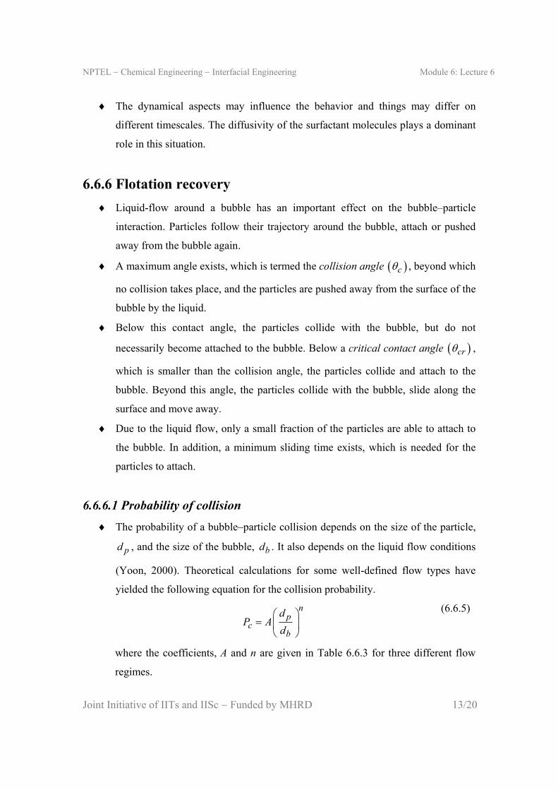
6.6.6 Flotation recovery
Liquid-flow around a bubble has an important effect on the bubble–particle
interaction. Particles follow their trajectory around the bubble, attach or pushed
away from the bubble again.
A maximum angle exists, which is termed the collision angle c , beyond which
no collision takes place, and the particles are pushed away from the surface of the
bubble by the liquid.
Below this contact angle, the particles collide with the bubble, but do not
necessarily become attached to the bubble. Below a critical contact angle cr ,
which is smaller than the collision angle, the particles collide and attach to the
bubble. Beyond this angle, the particles collide with the bubble, slide along the
surface and move away.
Due to the liquid flow, only a small fraction of the particles are able to attach to
the bubble. In addition, a minimum sliding time exists, which is needed for the
particles to attach.
6.6.6.1 Probability of collision
The probability of a bubble–particle collision depends on the size of the particle,
pd , and the size of the bubble, bd . It also depends on the liquid flow conditions
(Yoon, 2000). Theoretical calculations for some well-defined flow types have
yielded the following equation for the collision probability.
np
cb
dP A
d
(6.6.5)
where the coefficients, A and n are given in Table 6.6.3 for three different flow
regimes.

NPTEL Chemical Engineering Interfacial Engineering Module 6: Lecture 6
Joint Initiative of IITs and IISc Funded by MHRD 14/20
Table 6.6.3 The values of A and n for different flow types
Flow type Reynolds number A n
Stokes 0 Re 300 1.5 2
Intermediate 4 5300 Re 10 10 0.56
3 16 Re 3001.5 1
1 0.249 Re
2
Potential 5Re 10 3 1
Re = Reynolds number of bubble
The condition for using the values of A and n given in Table 6.6.3 is that the flow
around the bubble is symmetric. In practice, flow around bubbles is always
asymmetric, but the values will give an indication of the collision probability.
6.6.6.2 Probability of attachment
Bubble–particle attachment depends largely on the hydrophobicity of particles,
which means the ability of particles to adhere to the surface of the bubble. When
the particles are sufficiently hydrophobic to attach to the surface, there is also still
the possibility of particle to collide with the bubble surface and slide along the
surface away from the bubble again.
The probability of attachment, viz., the probability that particles collide with the
bubble, slides along its surface and attaches, depends on the induction time and
the sliding time of the particle, i.e.,
ic
s
tP
t
(6.6.6)
where it is the induction time (i.e., the time required to thin and disrupt the liquid
film between bubble and particle), and st is the sliding time (i.e., the minimum
contact time of particles sliding along the surface of a bubble).
If the induction time is greater than the sliding time, particles will never be able to
attach to the bubble surface.

NPTEL Chemical Engineering Interfacial Engineering Module 6: Lecture 6
Joint Initiative of IITs and IISc Funded by MHRD 15/20
6.6.6.3 Flotation recovery
Probabilities of collision and attachment are important quantities to determine the
collection efficiency of a flotation process. The quantity describing the efficiency
of the process is termed flotation recovery (R). It is defined as the number of
particles collected by the gas bubble divided by the number of particles in the
slurry passing by the bubble. It is a quantification of the efficiency of the flotation
process. The equation for flotation recovery is given by (Koper, 2009),
24
c
p b
NR
d d Hc
(6.6.7)
where c is the particle concentration, H is a given height within which the
flotation recovery is calculated, and cN is the amount of collected particles
during the traversal of the distance, H.
The quantity, cN , can be calculated by multiplying the probability of a particle
being collected with the number of possible particle collisions icN , i.e.,
ic cN PN (6.6.8)
The probability of particle collection by a bubble P is dependent on the
probability of bubble–particle collision cP , probability of adhesion aP , and
the probability of detachment dP . It is given by (Yoon, 2000),
1c a dP P P P (6.6.9)
The number of possible collisions, which is the maximum number of all collected
particles, depends on the diameters of bubble and the particle, and also on the
rising velocity of the bubble u and the particle settling velocity v as,
2
4ic p bN d d u v c
(6.6.10)
The flotation recovery R can be computed from the expression,
1 1c a du
R P P Pv
(6.6.11)

NPTEL Chemical Engineering Interfacial Engineering Module 6: Lecture 6
Joint Initiative of IITs and IISc Funded by MHRD 16/20
Example 6.6.2: For a laboratory flotation of an iron ore in water, it was observed that 2
mg was collected while traversing 2 m of the flotation column. The concentration of the
ore in water was 0.5 kg/m3. The average diameter of the bubbles was 2 mm and the
average diameter of the particles was 0.1 mm. Compute flotation recovery.
Solution:
Given data: 41 10 mpd , 32 10 mbd , 2 mH , 30.5 kg/mc and
62 10 kgcN
6 6
2 63 3
2 10 2 100.578
3.46 100.1 10 2 10 2 0.54
R
Therfore, the flotation recovery was 57.8%.
6.6.7 Micro-processes in flotation
If a particle indeed becomes attached to a bubble, a series of steps takes place
from the particle–bubble contact until final attachment. These micro-processes
can be summarized as follows.
(i) Thinning of the intervening liquid film on the bubble surface
(ii) Rupture of the film
(iii) Formation of a three-phase contact line and attachment
(iv) Detachment
Flotation can only take place when the thin liquid film between particle and
bubble is unstable. During the thinning of the film, the hydrodynamic and
interfacial forces play an important role (see Lectures 3 & 4 of Module 5). The
film reaches a critical thickness and then it ruptures.
The energy required for the formation of the primary hole in the film is provided
by the kinetic energy of the particles. This amount of work can be seen as the
minimal energy needed for flotation to occur by creation of the first three-phase
contact.

NPTEL Chemical Engineering Interfacial Engineering Module 6: Lecture 6
Joint Initiative of IITs and IISc Funded by MHRD 17/20
The three-phase contact line, which is formed after attachment of the particle to
the bubble, gives rise to the formation free energy. The formation free energy per
unit length of contact line is the line tension,
, ,T V A
G
L
(6.6.12)
The typical value of line tension, , is of the order of 1010 J/m . The change in
surface free energy, dG , is given by,
SV LV SLdG dA dA dA dL (6.6.13)
A solid–vapor interface is formed whereas a liquid–vapor and a solid–liquid
interface are removed, and a three-phase contact line is formed. The capillary
force at this line is (Koper, 2009),
SV LV SL
d G dL
dA dA
(6.6.14)
2dL dr , 2 cosdA rdr
1 222
cos 1p
r
d
, 1
cos
dL
dA r
(6.6.15)
From Young–Dupré equation [eq. (2.2.8)],
cosSV SL LV (6.6.16)
For the contact angle, , one may use the dynamic contact angle (see Lecture 2
of Module 2), which is experimentally determined. It varies from the equilibrium
contact angle, and also varies with the contact line motion. The contact line
changes with the instantaneous radius, r. When r becomes very small, the
capillary force becomes indefinitely large. Therefore, a certain critical radius, crr ,
is needed to make three-phase contact line expansion possible. This radius is
associated with the critical amount of energy. This means that there is a minimal
pore opening needed to give rise to three-phase contact line expansion.
When a particle is attached to a bubble, different forces (e.g., gravity force,
capillary force on the three-phase contact area, hydrodynamic pressure of the
liquid column on the contact area, and additional hydrodynamic forces due to the

NPTEL Chemical Engineering Interfacial Engineering Module 6: Lecture 6
Joint Initiative of IITs and IISc Funded by MHRD 18/20
motion and mass of the particle) act on the particle, which are balanced by the
buoyancy force. A repulsive force needs to be overcome before the detachment
can take place.
NPTEL Chemical Engineering Interfacial Engineering Module 6: Lecture 6
Joint Initiative of IITs and IISc Funded by MHRD 19/20
Exercise
Exercise 6.6.1: Calculate the flotation recovery of an ore in water if the velocity of
bubble is 20 mm/s and the settling velocity of particle is 10 mm/s. The probability of
adhesion is 0.7 and the probability of detachment is 0.3. The diameter of the bubble is 1
mm and the same of the particle is 100 m.
Exercise 6.6.2: Show the the ratios given in Table 6.6.2 are dimensionless.
Exercise 6.6.3: Derive eq. (6.6.11)
Exercise 6.6.4: Answer the following questions clearly.
(a) What is froth flotation? Give three examples.
(b) Write the names of three industrial flotation cells.
(c) What is collector? What is its role in flotation?
(d) Define depressant and activator? Why are they used?
(e) At what size of the particle does the role of interfacial force become more
significant than inertial and gravitational forces? Explain why.
(f) Explain the conditions under which flotation can occur.
(g) What is the significance of Zisman plot is flotation?
(h) Define flotation recovery.
(i) Define collision angle and critical contact angle.
(j) What is probability of collision? How would you calculate it?
(k) Explain the processes involved at the micro-level in flotation.

NPTEL Chemical Engineering Interfacial Engineering Module 6: Lecture 6
Joint Initiative of IITs and IISc Funded by MHRD 20/20
Suggested reading
Textbooks
A. V. Nguyen and H. J. Schulze, Colloidal Science of Flotation (Surfactant
Science Series, vol. 118), Marcel Dekker, New York, 2004, Chapter 1.
G. J. M. Koper, An Introduction to Interfacial Engineering, VSSD, Delft, 2009,
Chapter 8.
Reference books
L. L. Schramm, Emulsions, Foams, and Suspensions, Wiley-VCH, Weinheim,
2005, Chapter 10.
Journal articles
R. –H. Yoon, Int. J. Miner. Process., 58, 129 (2000).