Lecture 5 Database Systems · enterprise? What information ... (ER diagrams). Can map an ER diagram...
49
08/03/2015 1 Database Systems Instructor: M.Imran Khalil [email protected] Resource:Imrankhalil3.wordpress.com ©University of Sargodha Canal Campus Lahore Lecture 5 Overview - important points Some introductory information ERD diagrams Normalization Other stuff
Transcript of Lecture 5 Database Systems · enterprise? What information ... (ER diagrams). Can map an ER diagram...

08/03/2015
1
Database SystemsInstructor: M.Imran Khalil
Resource:Imrankhalil3.wordpress.com
©University of Sargodha Canal Campus Lahore
Lecture 5
Overview - important points
Some introductory information
ERD diagrams
Normalization
Other stuff

08/03/2015
2
SDLC - Where are we?
1. Systems planning phase
2. Systems analysis phase
3. Systems design phase
4. Systems implementation phase
5. Systems operation, support, and security phase
Data design
Overview of Database Design
What are the entities and relationships in the
enterprise?
What information about these entities and relationships
should we store in the database?
What are the integrity constraints or business rules that
hold?
A database `schema’ in the ER Model can be
represented pictorially (ER diagrams).
Can map an ER diagram into a relational schema.

08/03/2015
3
Database Design
Three phases of database design
Conceptual database design
Logical database design
Physical database design.
Conceptual Database Design
Process of constructing a model of the data
used in an enterprise, independent of all
physical considerations.
Data model is built using the information in
users’ requirements specification.
Conceptual data model is source of
information for logical design phase.

08/03/2015
4
Logical Database Design
Process of constructing a model of the data used
in an enterprise based on a specific data model
(e.g. relational), but independent of a particular
DBMS and other physical considerations.
Conceptual data model is refined and mapped on
to a logical data model.
Physical Database Design
Process of producing a description of the database
implementation on secondary storage.
Describes base relations, file organizations, and indexes
used to achieve efficient access to data. Also describes any
associated integrity constraints and security measures.
Tailored to a specific DBMS system.
© Pearson Education Limited 1995, 2005

08/03/2015
5
Overview of Database Design
Conceptual design: (ER Model is used for this.)
What are the entities and relationships we need?
Logical design:
Transform ER design to Relational Schema
Schema Refinement: (Normalization)
Check relational schema for redundancies and related anomalies.
Physical Database Design and Tuning:
Consider typical workloads; (sometimes) modify the
database design; select file types and indexes.
Storage choices
File based
Text-based - XML
Binary
Database systems
Relational
Object-based/oriented
08/03/2015
6
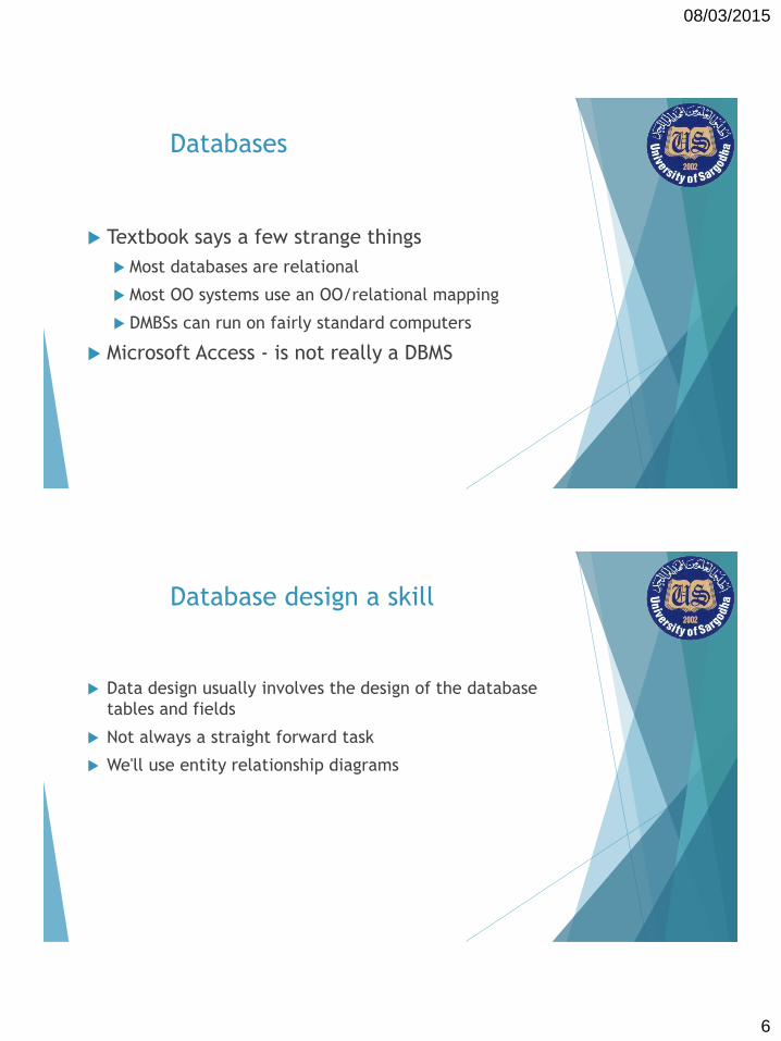
Databases
Textbook says a few strange things
Most databases are relational
Most OO systems use an OO/relational mapping
DMBSs can run on fairly standard computers
Microsoft Access - is not really a DBMS
Database design a skill
Data design usually involves the design of the database
tables and fields
Not always a straight forward task
We'll use entity relationship diagrams

08/03/2015
7
Introduction
Entity Relationship Modelling (ERM)
A technique used to analyze & model the data in organizations using an Entity Relationship (E-R) diagram.
Entity-Relationship Model( E-Model)
A logical representation of the data for an organization or for a business area.
Entity-Relationship diagram (E-R diagram)
A graphical representation of an entity-relationship model.
Why ERDs?
Entity Relationship Diagrams are a major data modeling tool and will help organize the data in your project
This process has proved to enable the analyst to produce a good database structure so that the data can be stored and retrieved in a most efficient manner.
By using a graphical format it may help communication about the design between the designer and the user and the designer and the people who will implement it.

08/03/2015
8
Entity relationship diagram (ERD)
A data model utilizing several notations to depict data in
terms of the entities and relationships described by that
data.
ERD has 3 major constructs:-
Entity
Relationships
Attributes

08/03/2015
9
Entity
Anything real or abstract about which we will store data
Five classes:
Roles
events
Locations
tangible things
concepts
Entity in ERD
Entities
An entity is anything real or abstract about which we want to store data. In short, anything, which an organization needs to store data about
Entity types fall into five classes
Roles
e.g. Employee, Student
Events
e.g. Payment, Borrow
Locations
e.g. Campus, City
Tangible things or concepts
e.g. Department, Book

08/03/2015
10
Persons: agency, contractor, customer, department, division, employee, instructor, student, supplier.
Places: sales region, building, room, branch office, campus.
Objects: book, machine, part, product, raw material, software license, software package, tool, vehicle model, vehicle.
Events: application, award, cancellation, class, flight, invoice, order, registration, renewal, requisition, reservation, sale, trip.
Concepts: account, block of time, bond, course, fund, qualification, stock.
Entity
Entity – a class of persons, places, objects, events, or concepts about which we need to capture and store data.
Named by a singular noun
What Should an Entity Be?
SHOULD BE:
An object that will have many instances in the database
An object that will be composed of multiple attributes
An object that we are trying to model
SHOULD NOT BE:
A user of the database system
An output of the database system (e.g. a report)
08/03/2015
11
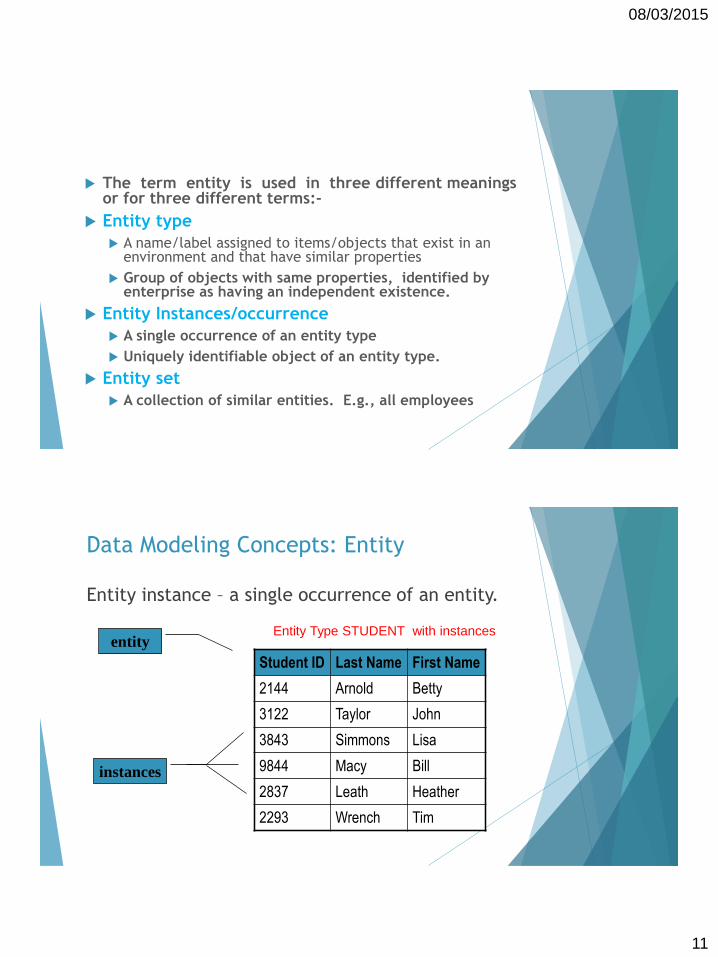
The term entity is used in three different meanings or for three different terms:-
Entity type
A name/label assigned to items/objects that exist in an environment and that have similar properties
Group of objects with same properties, identified by enterprise as having an independent existence.
Entity Instances/occurrence
A single occurrence of an entity type
Uniquely identifiable object of an entity type.
Entity set
A collection of similar entities. E.g., all employees
Data Modeling Concepts: Entity
Entity instance – a single occurrence of an entity.
Student ID Last Name First Name
2144 Arnold Betty
3122 Taylor John
3843 Simmons Lisa
9844 Macy Bill
2837 Leath Heather
2293 Wrench Tim
instances
entityEntity Type STUDENT with instances

08/03/2015
12
Entity Instance & Set
A particular object belonging to a particular entity type
Entity Type: Employee
Entity Instance: M. Sharif
Entity Set: All employees
Types of Entity Types
Entity types can be classified:
regular/strong/independent Entity Types
weak/dependent Entity Types

08/03/2015
13
Weak Entity Types
An entity type whose instances cannot exist without
being linked with instances of some other entity
type, i.e., they cannot exist independently
Strong Entity Type
A strong/regular entity type is the one whose instances
can exist independently, i.e., without being linked to
other instances
Strong ETs have their own identity

08/03/2015
14
Naming Entity Types
Singular noun recommended
Organization specific names
Write in capitals
Abbreviations can be used, be consistent
Symbols

08/03/2015
15
Data Modeling Concepts: Attributes
Attribute: Entities are further described by their attributes (also called data elements)
– A characteristics common to all or most instances of an entity
– property or characteristic of an entity type
– a descriptive property or characteristic of an entity. Synonyms include element, property, and field.
Just as a physical student can have attributes, such as hair color, height, etc., data entity has data attributes
Classifications of attributes
Simple versus Composite Attribute
Single-Valued versus Multivalued Attribute
Stored versus Derived Attributes

08/03/2015
16
Attributes
Simple Attribute
Attribute composed of a single component with an
independent existence.
Composite Attribute
Attribute composed of multiple components, each with
an independent existence.
For name: firstName+lastName
Attributes
Single-valued Attribute
Attribute that holds a single value for each occurrence
of an entity type.
Multi-valued Attribute
Attribute that holds multiple values for each occurrence
of an entity type.
For example:
address should be multi-valued attribute
A person can had multiple address
33

08/03/2015
17
Attributes
Derived Attribute
Attribute that represents a value that is derivable from value
of a related attribute, or set of attributes, not necessarily in the
same entity type.
34
Relationships in ERD
Relationships
A data relationship is a natural association that exist
between one or more entities
Example
EMPLOYEE works in DEPARTMENT
EQUIPMENT is allocated to PROJECT
ESTEEM is a type of CAR
08/03/2015
18
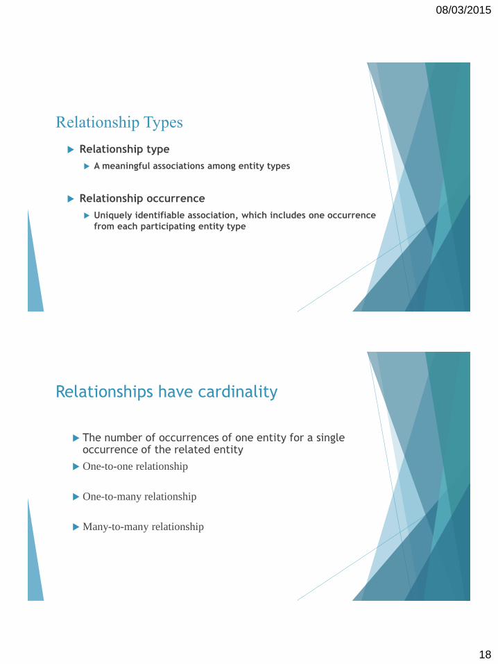
Relationship Types
Relationship type
A meaningful associations among entity types
Relationship occurrence
Uniquely identifiable association, which includes one occurrence
from each participating entity type
Relationships have cardinality
The number of occurrences of one entity for a single occurrence of the related entity
One-to-one relationship
One-to-many relationship
Many-to-many relationship

08/03/2015
19
Cardinality of Relationships
One – to – One
Each entity in the relationship will have exactly one related entity
One – to – Many
An entity on one side of the relationship can have many related entities, but an entity on the other side will have a maximum of one related entity
Many – to – Many
Entities on both sides of the relationship can have many related entities on the other side
One-to-one Relationships
This type of relationship takes place when a single occurrence
of an entity is related to just one occurrence of a second entity
Example:
PERSON owns a CAR
CAR is owned by a PERSONPerson
Car
owns
Person
Car
own by

08/03/2015
20
One-to-many Relationships
This type of relationship takes place when a single occurrence
of an entity is related to many occurrence of a second entity
Example:
DEPARTMENT has EMPLOYEE
EMPLOYEE works in DEPARMENTDepartment
Employee
has
Department
Employee
works in
Many-to-many Relationships
This type of relationship takes place when many occurrence of
an entity are related to many occurrence of a second entity
Example:
STAFF work in PROJECT
PROJECT assigned to STAFFStaff
Project
works in
Staff
Project
assigned to

08/03/2015
21
Key Constraints (Contd.)
Several types of key-constraints:
Many-to-Many1-to-1 1-to Many Many-to-1
Cardinality Constraints
Cardinality Constraints - the number of instances of one entity that can or must be associated with each instance of another entity.
Minimum Cardinality
If zero, then optional
If one or more, then mandatory
Maximum Cardinality
The maximum number

08/03/2015
22
Data Modeling Concepts: Degree
Degree – the number of entities that participate in the relationship.
A relationship between two entities is called a binary relationship.
A relationship between three entities is called a 3-ary or ternary
relationship.
A relationship between different instances of the same entity is called a
recursive relationship.
Degree of relationships –
One entity
related to
another of
the same
entity type
Entities of
two
different
types
related to
each other
Entities of
three different
types related
to each other

08/03/2015
23
Unary relationships
Binary relationships

08/03/2015
24
Ternary relationships
Note: a relationship can have attributes of its own
Quaternary relationship called Arranges

08/03/2015
25
Relationship Types
Recursive Relationship
Relationship type where same entity type participates more than once in
different roles.
Relationships may be given role names to indicate purpose that each
participating entity type plays in a relationship.
50
Recursive Relationships
Relationship can exist between different occurrences of the
same type of entity
Example:
EMPLOYEE manager EMPLOYEE
NETWORK makes NETWORK
Employee
manager
Network
makes
08/03/2015
26
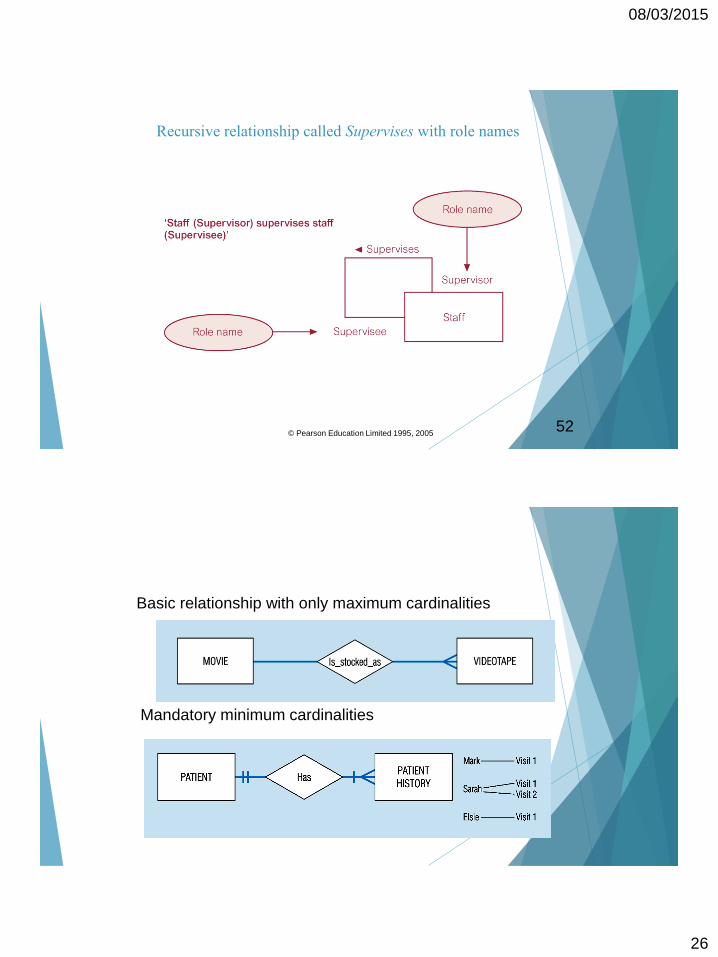
Recursive relationship called Supervises with role names
52© Pearson Education Limited 1995, 2005
Basic relationship with only maximum cardinalities
Mandatory minimum cardinalities

08/03/2015
27
Optional cardinalities with unary degree, one-to-one relationship
A ternary relationship with attributes

08/03/2015
28
Representing a bill-of -materials structure
A unary relationship with an attribute. This has a
many-to-many relationship
Examples of multiple relationships – entities can be related to
one another in more than one way
Employees and departments

08/03/2015
29
What is a Good Data Model?
A good data model is simple.
Data attributes that describe any given entity should describe only that entity.
Each attribute of an entity instance can have only one value.
A good data model is essentially no redundant.
Each data attribute, other than foreign keys, describes at most one entity.
Look for the same attribute recorded more than once under different names.
A good data model should be flexible and adaptable to future needs.
Key constraints: Examples
Example Scenario 1: An inventory database contains information about parts and manufacturers. Each part is constructed by exactly one manufacturer.
Example Scenario 2: A customer database contains information about customers and sales persons. Each customer has exactly one primary sales person.
What do the ER diagrams look like?

08/03/2015
30
Entity Relationship Diagram Methodology
An ERD design methodology
1. Identify entities
2. Find relationships
3. Draw rough ERD
4. Fill in cardinality
5. Define primary keys
6. Draw key-based ERD
7. Identify attributes
8. Map attributes
9. Draw fully attributes
10. Check results

08/03/2015
31
Example
A company has several departments. Each department has a supervisor and at least one employee. Employees must be assigned to at least one, but possibly more departments. At least one employee is assigned to a project, but an employee may be on vacation and not assigned to any projects. The important data fields are the names of the departments, projects, supervisors and employees, as well as the supervisor and employee number and a unique project number.
An ERD design methodology
1. Identify entities
2. Find relationships
3. Draw rough ERD
4. Fill in cardinality
5. Define primary keys
6. Draw key-based ERD
Identify roles, events, locations,
tangible things or concepts about
which the end-users want to
store data

08/03/2015
32
Example - entities
A company has several departments. Each department has a supervisor and at least one employee. Employees must be assigned to at least one, but possibly more departments. At least one employee is assigned to a project, but an employee may be on vacation and not assigned to any projects. The important data fields are the names of the departments, projects, supervisors and employees, as well as the supervisor and employee number and a unique project number.
An ERD design methodology
1. Identify entities
2. Find relationships
3. Draw rough ERD
4. Fill in cardinality
5. Define primary keys
6. Draw key-based ERD
Find natural associations between
pairs of entities using a
relationship matrix

08/03/2015
33
Relationship Matrix
Department Employee Supervisor Project
Department
Employee
Supervisor
Project
Relationship Matrix
Department Employee Supervisor Project
Department is assigned run by
Employee belongs to works on
Supervisor runs
Project uses

08/03/2015
34
An ERD design methodology
1. Identify entities
2. Find relationships
3. Draw rough ERD
4. Fill in cardinality
5. Define primary keys
6. Draw key-based ERDPut entities in rectangles and
relationships on line segments
connecting the entities
ERD Components
Entity1 Entity2
Relationship

08/03/2015
35
An ERD design methodology
1. Identify entities
2. Find relationships
3. Draw rough ERD
4. Fill in cardinality
5. Define primary keys
6. Draw key-based ERDPut entities in rectangles and
relationships on line segments
connecting the entities
Department Supervisor
run by
ProjectEmployee
works on
is assigned

08/03/2015
36
An ERD design methodology
1. Identify entities
2. Find relationships
3. Draw rough ERD
4. Fill in cardinality
5. Define primary keys
6. Draw key-based ERD
Determine the number of
occurences of one entity for
a single occurrence of the
related entity
Cardinality
For each entity X and every entity Y it has a relationship with
Each X has NUMBER Y
For example,
Each department has exactly one supervisor

08/03/2015
37
Symbol Meaning
One and only one
One or more
Zero or more
Zero or one
Sample E-R Diagram

08/03/2015
38
Summary of multiplicity constraints
Basic E-R Notation
Entity
symbols
Relationship
symbols
Attribute
symbols
A special
entity that is
also a
relationship

08/03/2015
39
An ERD design methodology
1. Identify entities
2. Find relationships
3. Draw rough ERD
4. Fill in cardinality
5. Define primary keys
6. Draw key-based ERD
Determine the number of
occurences of one entity for
a single occurrence of the
related entity
Cardinality "list"
Each department has exactly one supervisor.
A supervisor is in charge of one and only one department.
Each department is assigned at least one employee.
Each employee works for at least one department.
Each project has at least one employee working on it.
An employee is assigned to 0 or more projects.

08/03/2015
40
Department Supervisor
run by
ProjectEmployee
works on
is assigned
An ERD design methodology
1. Identify entities
2. Find relationships
3. Draw rough ERD
4. Fill in cardinality
5. Define primary keys
6. Draw key-based ERD
Identify the data attributes that
uniquely identify one and only
one occurrence of the related
entity

08/03/2015
41
Example - primary keys
A company has several departments. Each department has a supervisor and at least one employee. Employees must be assigned to at least one, but possibly more departments. At least one employee is assigned to a project, but an employee may be on vacation and not assigned to any projects. The important data fields are the names of the departments, projects, supervisors and employees, as well as the supervisor and employee number and a unique project number.
Attributes
Entity1 Entity2
Relationship
Attribute Primary Key

08/03/2015
42
Department Supervisor
run by
ProjectEmployee
works on
is assigned
Supervisor
Number
Project
Number
Employee
Number
Department
Name
An ERD design methodology
1. Identify entities
2. Find relationships
3. Draw rough ERD
4. Fill in cardinality
5. Define primary keys
6. Draw key-based ERD
Eliminate many-to-many
relationships and include
primary and foreign keys

08/03/2015
43
Many-to-many = bad
Cannot be represented in the relational model and pose some other problems
Solution
Replace it with an association entity
Each entity forms a relation with it
Verbal Example
Many to many
A department has one or more employees
An employee belongs to one or more departments
Associative entity
A department has one or more Employee-Department
An employee has one or more Employee-Department

08/03/2015
44
Department
Employee
is assigned
Department
Employee
is assigned
Employee-
Department involves
08/03/2015
45
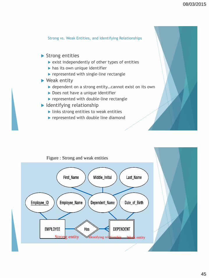
Strong vs. Weak Entities, and Identifying Relationships
Strong entities
exist independently of other types of entities
has its own unique identifier
represented with single-line rectangle
Weak entity
dependent on a strong entity…cannot exist on its own
Does not have a unique identifier
represented with double-line rectangle
Identifying relationship
links strong entities to weak entities
represented with double line diamond
Figure : Strong and weak entities
Strong entity Weak entityIdentifying relationship

08/03/2015
46
Associative Entities
It’s an entity – it has attributes
AND it’s a relationship – it links entities together
When should a relationship with attributes instead be an associative entity?
All relationships for the associative entity should be many
The associative entity could have meaning independent of the other entities
The associative entity preferably has a unique identifier, and should also have other attributes
The associative may be participating in other relationships other than the entities of the associated relationship
Ternary relationships should be converted to associative entities
Figure : An associative entity (CERTIFICATE)
Associative entity involves a rectangle with a diamond inside.
Note that the many-to-many cardinality symbols face toward
the associative entity and not toward the other entities
08/03/2015
47
Repeating groups, normalisation
Normalization
Eliminate redundancy
Organise data efficiently
Reduce potential for anomalies
Normal form - "how normalised" a relational database is
There are 6 normal forms
Text limited to 3
Conclusions
Just a small start
An important process
Get lots of practice
Ask lots of questions

08/03/2015
48
7. Identify Attributes
Objective: Name the information details (fields), which are essential to the
system under development
The only attributes indicated are the names ofA company has several departments.
Each department has a supervisor and at least one employee.
Employees must be assigned to at least one, but possibly more
departments.
At least one employee is assigned to a project, but an employee
may be on vacation and not assigned to any projects.
The important data fields are the names of the departments,
projects, supervisors, and employees, as well as, the supervisor
numbers, employee numbers and project numbers.
8. Map Attributes
Objective: For each attribute, match it with exactly one entity that it describes
Attribute Entity
Department Name Department
Employee Number Employee
Employee Name Employee
Supervisor Number Supervisor
Supervisor Name Supervisor
Project Name Project
Project Number Project

08/03/2015
49
Data Dictionary Sample
An example for a Banking System
Customer Transaction Account
First Name Last Name
Middle Name
Name
PAN
Gender
AddressTelephone
Customer No
Transaction No Date
TType
Amount
TP Account
Account No
Account No Account Type
Customer No Balance