5.5 Numerical Integration. concave down concave up concave down concave up concave down.
Upload
nguyennguyetCategory
view
215download
0
Image formation Ray tracing Calculation
Lecture 3.3.
Lenses Convex Concave
Optical instruments
Mirrors Convex Concave
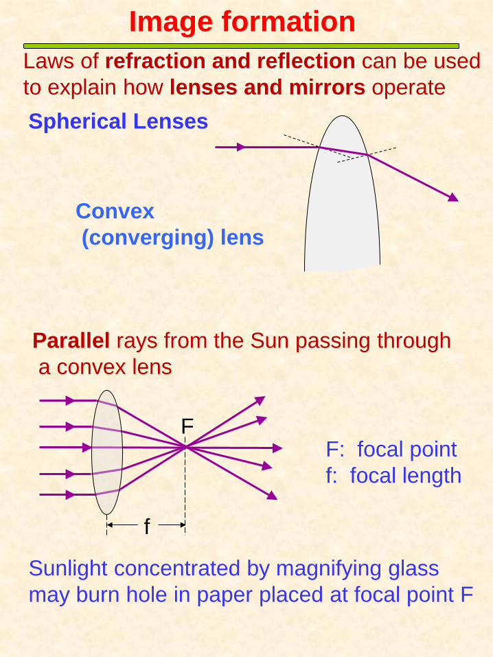
Image formation
Spherical Lenses
Convex (converging) lens
Laws of refraction and reflection can be used to explain how lenses and mirrors operate
Parallel rays from the Sun passing through a convex lens
Sunlight concentrated by magnifying glass may burn hole in paper placed at focal point F
f
F F: focal point f: focal length
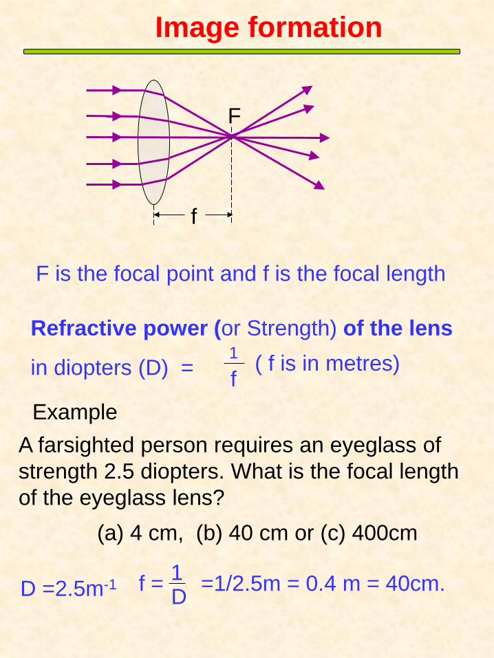
Example A farsighted person requires an eyeglass of strength 2.5 diopters. What is the focal length of the eyeglass lens?
D =2.5m-1 f = 1 D =1/2.5m = 0.4 m = 40cm.
F is the focal point and f is the focal length
1
f
Refractive power (or Strength) of the lens
in diopters (D) = ( f is in metres)
f
F
Image formation
(a) 4 cm, (b) 40 cm or (c) 400cm

F F
s′
h′
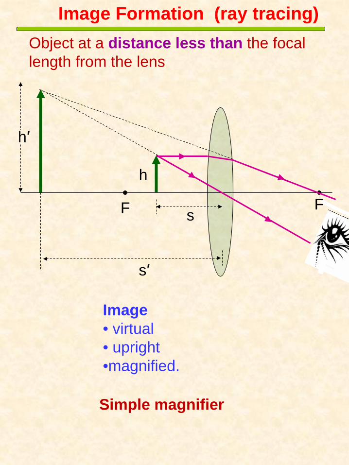
Image Formation (ray tracing)
Ray 1 entering lens parallel to optic axis will exit and pass through the focal point Ray 2 passing through the focal point will exit the lens and travel parallel to optic axis
Ray 3 will undergo small deviation (displacement (not shown) (thin lens)
3
Real, inverted image formed Real image (may be projected and displayed on a screen)
Object at a distance greater than the focal length from the lens
2
1
s
h
Rays are reversible
F F s
s′
h
h′
Image Formation (ray tracing)
Image • virtual • upright •magnified.
Object at a distance less than the focal length from the lens
Simple magnifier

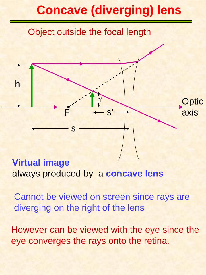
Concave (diverging) lens
F
Dashed lines indicate the direction from which the rays appear to come
f
Rays entering lens parallel to axis appear to originate at focal point
Optic axis
Concave (diverging) lens
s
s′ F
h h′
Virtual image always produced by a concave lens
Cannot be viewed on screen since rays are diverging on the right of the lens
However can be viewed with the eye since the eye converges the rays onto the retina.
Object outside the focal length
Optic axis
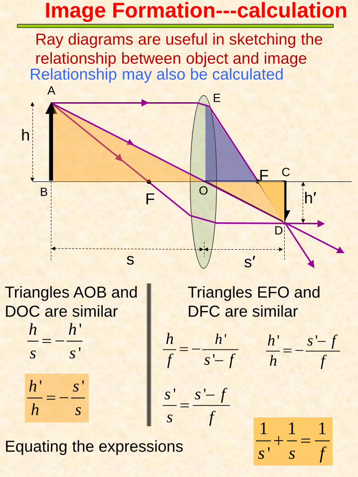
Ray diagrams are useful in sketching the relationship between object and image
Relationship may also be calculated
F F
s s′
h
h′
A
B O C
D
Triangles AOB and DOC are similar
''
h hs s= − ' 'h s f
h f−= −
1 1 1's s f+ =
E
Triangles EFO and DFC are similar
Equating the expressions
' 'h sh s= −
''hh
f s f= −
−
Image Formation---calculation
' 's s fs f
−=

1 1 1's s f+ =Thin lens formula
Object distance s positive if object is in front of lens negative if object is behind lens
Image distance s′ positive if image is formed behind the lens (real) negative if is formed in front of the lens (virtual)
Focal length f •positive -- convex lens •negative --concave lens
Image ---calculation
F
s s′
h
h′ B
F

F
s s′
h
h′ B
F
'hMh
=
Magnification is defined as
M Negative : inverted image
M Positive : upright image
'sMs
= − or
Magnification

Simple magnifier
Object placed inside focal length of converging lens;
F F s
s′
h h′
Image viewed. •Virtual, •Magnified •Upright
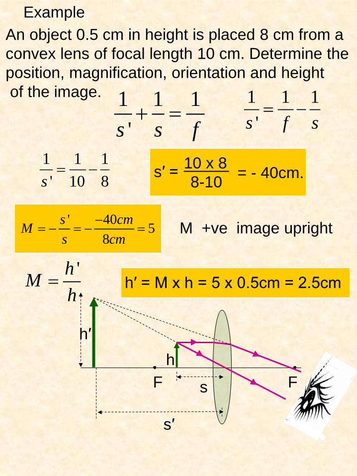
Example An object 0.5 cm in height is placed 8 cm from a convex lens of focal length 10 cm. Determine the position, magnification, orientation and height of the image. 1 1 1
's s f+ =
1 1 1's f s= −
1 1 1' 10 8s= − s′ = 10 x 8
8-10 = - 40cm.
' 40 58
s cmMs cm
−= − = − =
h′ = M x h = 5 x 0.5cm = 2.5cm 'hM
h=
M +ve image upright
F F s
s′
h h′

Effective focal length (feff) of combination of a number of thin lenses close together
1 2
1 1 1 ......efff f f
= + +
Effective refractive power (or strength) (Seff) of combination of thin lenses close together
1 2 .....effS S S= + +
Combining Lenses
Determine the combined strength of a thin convex lens and a thin concave lens placed close together if their respective focal lengths are 10cm and -20cm.
1
f Strength S, in diopters (D) = ( f is in metres)
1 2
1 1 1eff
eff
Sf f f
= = + 1 1.1 .2effS
m m= −
10 5 5effS diopters= − =

An object is placed 45 cm from a lens of focal length -25 cm. Determine the position, magnification, and orientation of the image.
1 1 1's s f+ = 1 1 1
's f s= −
M +ve image upright
Example
1 S’
1 -25 cm
1 45 cm = - S’ = -16.1 cm
M = - S’ S M = - -16.1 cm
45 cm = 0.36
s
s′ F
h h′ Optic
axis

Mirrors Flat Mirror Concave Mirror Convex Mirror
Curved mirrors analogous to lenses Ray tracing and thin lens equation also valid. real and virtual images are also formed
Upright, virtual image
Object and image distance equal
Flat Mirror
d d object image

Spherical Mirrors
Spherical mirror
C
R
Hollow sphere
Spherical mirror is a section hollow sphere
Principal or optic axis
Radius of curvature R = 2f

Curved (Spherical) Mirrors
F f
f F
Concave mirror (converging)
Convex mirror (diverging)
Thin lens formula may be used to determine object and image distances and focal lengths etc
Real image : inverted (h′ negative), positive image distance s′ (RHS of lens, LHS of mirror) Virtual image: upright (h′ positive), negative image distance s′ (LHS of lens, RHS of mirror)
Positive focal length
Negative focal length
For all single lenses and mirrors:

Mirrors Concave shaving/makeup mirrors
C F
Image is virtual, upright and enlarged.
Object placed at distance < f from mirror
Question: if object is placed at the focal point, where is image located?
Application: searchlight

Mirrors Example
An object is positioned 5 cm in front of a concave mirror of focal length 10 cm. Determine the location of its image and its characteristics.
1 1 1's s f+ =
s = 5 cm f = 10 cm
1 1 1's f s= −
1 1 1' 10 5s cm cm= −
1 1 2 1' 10 10 10s cm cm cm= − = − S’ = -10cm
Characteristics. •Image virtual •Located behind mirror
'sMs
= −
105
2
cmMcm
M
−= −
=
Optical instruments
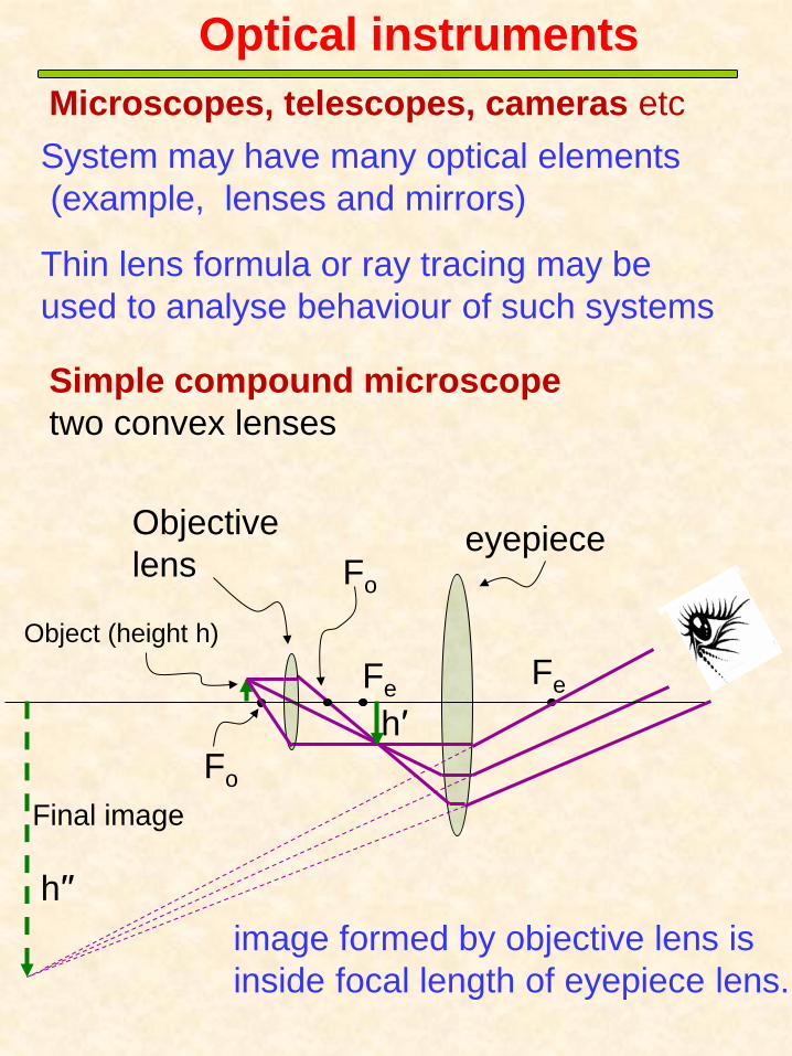
System may have many optical elements (example, lenses and mirrors)
Microscopes, telescopes, cameras etc
Thin lens formula or ray tracing may be used to analyse behaviour of such systems
Simple compound microscope two convex lenses
Fo
Fe
h′′
eyepiece
Fe
Objective lens
h′
Fo
Object (height h)
Final image
image formed by objective lens is inside focal length of eyepiece lens.
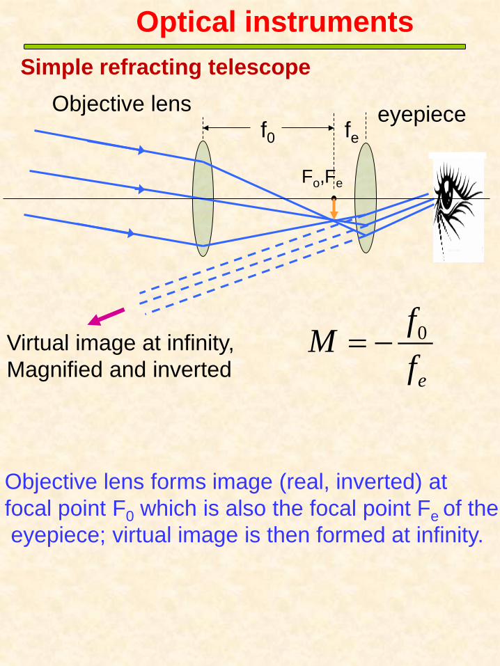
Simple refracting telescope
Fe
Objective lens eyepiece
Fo,
Optical instruments
Virtual image at infinity, Magnified and inverted
Objective lens forms image (real, inverted) at focal point F0 which is also the focal point Fe of the eyepiece; virtual image is then formed at infinity.
0
e
fMf
= −
f0 fe
Optical instruments
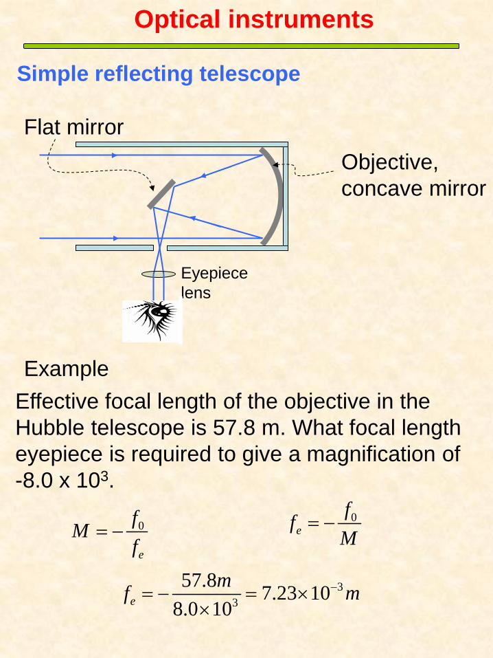
Effective focal length of the objective in the Hubble telescope is 57.8 m. What focal length eyepiece is required to give a magnification of -8.0 x 10³.
0
e
fMf
= −0
effM
= −
33
57.8 7.23 108.0 10e
mf m−= − = ××
Eyepiece lens
Objective, concave mirror
Flat mirror
Simple reflecting telescope
Example

Optical instruments
Medical loupes Galilean Design objective
eyepiece Operating site
Typically Magnification m ≈ 2.5 → 4.5 Optical design allows
observer focus at infinity thereby relieving eyestrain
Typical working distance 28-38 cm
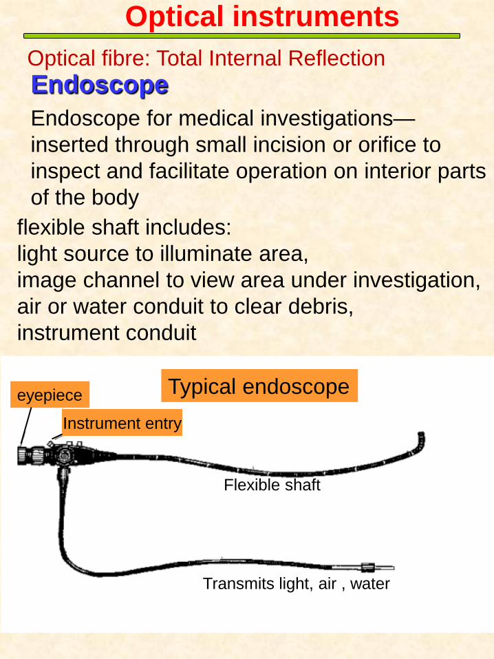
Endoscope for medical investigations— inserted through small incision or orifice to inspect and facilitate operation on interior parts of the body
flexible shaft includes: light source to illuminate area, image channel to view area under investigation, air or water conduit to clear debris, instrument conduit
Endoscope
Typical endoscope eyepiece
Transmits light, air , water
Flexible shaft
Instrument entry
Optical instruments Optical fibre: Total Internal Reflection

Camera Optical instruments
CCD array
Real, inverted image formed on CCD array
Lens translated to change image distance to adjust for different object distances.
aperture

Example Microscope as shown in the previous figure has the following characteristics objective lens focal length = 0.7 cm eyepiece lens focal length = 4.5 cm separation between lenses = 21 cm. Object size = 0.01 cm. object to objective lens distance = 0.73 cm. Calculate total magnification produced and size of the final image.
1 1 1's s f+ = 1 1 1
's f s= −
image distance s′ due to objective lens
1 1 1' 0.7 0.73s= −
s′ = 17 cm
Magnification M0 = -s′/s = -17/0.73 = -23.3
size of the image = h′ =M0h = (-23.3)(0.01)cm = -0.233 cm.
M0 = h′/h Magnification negative because image is inverted
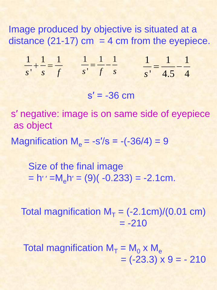
Magnification Me = -s′/s = -(-36/4) = 9
Size of the final image = h′ ′ =Meh′ = (9)( -0.233) = -2.1cm.
Total magnification MT = (-2.1cm)/(0.01 cm) = -210
Total magnification MT = M0 x Me = (-23.3) x 9 = - 210
1 1 1's s f+ =
1 1 1's f s= − 1 1 1
' 4.5 4s= −
Image produced by objective is situated at a distance (21-17) cm = 4 cm from the eyepiece.
s′ = -36 cm
s′ negative: image is on same side of eyepiece as object