Lecture 3 Current Metering “Six hours the waters run in...
10
Lecture 3 Current Metering “Six hours the waters run in, and six hours they run out, and the reason is this: when there is higher water in the sea than in the river, they run in until the river gets to be highest, and then it runs out again” The Last of the Mohicans, J.F. Cooper (1826) I. Introduction • Current metering in open channels is both a science and an art One cannot learn how to do current • • • II. T • • l- • Because of the bearing system, the vertical-shaft meters will operate at lower velocities than horizontal-axis current meters • metering well by only reading a book This is a velocity-area flow measurement method for open-channel flow A current meter is used to measure the velocity at several points in a cross section The velocities are multiplied by respective subsection areas to obtain flow rates ypes of Current Meters There are many companies that manufacture good quality current meters, and there are many types of current meters, including mechanical and electromagnetic versions Current meters with a rotating unit that senses the water velocity are either vertical- shaft or horizontal-shaft types • The vertical-axis current meter has a rotating cup with a bearing system that is simpler in design, more rugged, and easier to service and maintain than horizonta shaft (axis) current meters Current metering in an irrigation canal • The bearings are well protected from silty water, the adjustment is usually less sensitive, and the calibration at lower Price AA Current Meter velocities is more stable • Two of the commonly used vertical-axis current meters are the Price Type A (or AA) current meter and the Price Pygmy current meter, the latter intended for use with shallow flow depths and relatively low velocities (less than 0.5 fps, or 0.15 m/s) BIE 5300/6300 Lectures 35 Gary P. Merkley
Transcript of Lecture 3 Current Metering “Six hours the waters run in...

Lecture 3 Current Metering
“Six hours the waters run in, and six hours they run out, and the reason is this: when there is higher water in the sea than in the river, they run in until the river
gets to be highest, and then it runs out again”
The Last of the Mohicans, J.F. Cooper (1826) I. Introduction
• Current metering in open channels is both a science and an art
One cannot learn how to do current
•
•
•
II. T
•
•
l-
• Because of the bearing system, the vertical-shaft meters will operate at lower velocities than horizontal-axis current meters
•metering well by only reading a book
This is a velocity-area flow measurement method for open-channel flow
A current meter is used to measure the velocity at several points in a cross section
The velocities are multiplied by respective subsection areas to obtain flow rates
ypes of Current Meters
There are many companies that manufacture good quality current meters, and there are many types of current meters, including mechanical and electromagnetic versions Current meters with a rotating unit that senses the water velocity are either vertical-shaft or horizontal-shaft types
• The vertical-axis current meter has a rotating cup with a bearing system that is simpler in design, more rugged, and easier to service and maintain than horizontashaft (axis) current meters
Current metering in an irrigation canal
• The bearings are well protected from silty water, the adjustment is usually less sensitive, and the calibration at lower
Price AA Current Meter
velocities is more stable • Two of the commonly used vertical-axis
current meters are the Price Type A (or AA) current meter and the Price Pygmy current meter, the latter intended for use with shallow flow depths and relatively low velocities (less than 0.5 fps, or 0.15 m/s)
BIE 5300/6300 Lectures 35 Gary P. Merkley

• The commonly-used Price AA current meter can measure velocities up to about 8 fps (2.4 m/s)
es less than about
• None of the Price current meters can accurately measure velociti0.2 fps (0.07 m/s)
Price Type AA Current Meter
• tors disturb the flow less than vertical-axis cup rotors
•
• The horizontal-shaft current meters use a propeller These horizontal-axis robecause of axial symmetry in the flow direction Also, the horizontal-shaft current meters are less sensitive to vertic al velocity components in the channel
Price Pygmy Current Meter
• axis current meter is less susceptible to vegetative material moving with the water
• horizontal-axis current meters are the Ott (German), the Neyrpic
Because of its shape, the horizontal-becoming fouled by small debris andSome common (France) and the Hoff (USA)
Gary P. Merkley 36 BIE 5300/6300 Lectures

Ott Current Meters • Some recent models have proven to be both accurate and durable when used in
irrigation channels • Electromagnetic current meters are available that contain a sensor with the point
velocity displayed digitally • Some earlier models manifested considerable electronic noise under turbulent flow
conditions (even the latest models still have problems if near steel-reinforced concrete infrastructure, such as bridge piers)
• Present models yield more stable velocity readings, with averaging algorithms • However, recent lab tests have shown that the Price current meters are more
accurate than at least two types of electromagnetic meter throughout a range of velocities, and significantly more accurate at low velocities (J.M. Fulford 2002)
• Mechanical current meters automatically integrate and average velocities when
rotations per specific time interval are counted (e.g. count the rotations of the meter in a 30-s or 60-s interval)
• The photograph below shows a digital display from an Ott current meter. The number on the left is the elapsed time in seconds (to tenths of a second), and the number on the right is the number of revolutions of the propeller
BIE 5300/6300 Lectures 37 Gary P. Merkley

• th a t n rr e ou an tr co r a ow ov
the propeller, or other device, using a stopwatch if necessary
• olutio er n
• e lon e tio ap tim er su n g r te n ect as pr er d an w n fl tio t w
• The revolutions per second are directly proportional to the velocity of the flow, cordin th ib o in e e w
III. Care of the Equipment
• led, adjusted, and maintained
• e cur e ho e ed d te umt nee e us a ro e d th
being used and when being transported s a certain amount of hard
such as a broken pivot, chipped bearing, or bent giving velocity readings that are lower than
• nd abutments, water depth readings taken at s with the current meter attached to the ent the greatest hazards to the equipment
• nt during transport is generally due to careless
• provided by all manufacturers of current meter equipment, which charge measurements
• used when transporting the current meter,
• one location to another is one of the most
Wi raditio al cu ent m ter, y use elec onic unte s sh n ab e, earphones that emit a beep for each rotation of
Then you divide the number of revolutions by the elapsed seconds to get a value in rev ns p seco d Th ger th dura n (el sed e) p mea reme t, the reate the in gratioeff the opell spee s up d slo s dow with uctua ns in he flo (unless the flow is perfectly stable at the location)
ac g to e cal ration f the strum nt (se belo )
Accuracy in velocity measurements can only be expected when the equipment is properly assembTh rent m ter s uld b treat as a elica instr ent tha ds m ticulo care nd p tectiv custo y, bo when
• The current meter necessarily receiveusage that may result in damage,shaft that will result in the current meteractual velocities Measurements near bridge piers across-sections having irregular bed profilemeasuring line, and floating debris, repres(Corbett, et al. 1943) Damage to current meter equipmepacking or negligence A standard case isshould be used before and after taking disThe equipment case should always be even when the distance is relatively short Transport of assembled equipment fromcommon sources of damage
Gary P. Merkley 38 BIE 5300/6300 Lectures

IV. Spin Test
• A “spin test” can be performed on a current meter to determine whether it is pinning freely or not; this is done while the current meter is out of the water
, the USBR (1981) recommends putting the shaft in a s a quick turn by hand
• at least 3 minutes
s• For a Price-type current meter
vertical position and giving the cupIdeally, the cups should spin for , but if it is only about 1½ minutes
d, provided the velocity is not very low • hould come to a smooth and gradual stop
V. Cur
• towing tank, which
ge that travels on rails
•
arriage is recorded, as well
• r coordinates to verify that a straight-line
• ed on the rating equation for a
the current meter can still be useThe cups s
rent Meter Ratings
Usually, a current meter is calibrated in a is a small, straight open channel with stagnant water
• The current meter is attached to a carria(tracks) placed on the top of the towing tank Then, a series of trials are conducted wherein the current meter is towed at different constant velocities
• For each trial, the constant velocity of the cas the revolutions per second (rev/s) of the current meter These data are plotted on rectangularelationship exists; then, the equation is determined by regression analysis The table below is an example of a velocity rating bas
/s) = 0.665 (rev/s) + 0.009 (1)
current meter:
Velocity (m
BIE 5300/6300 Lectures 39 Gary P. Merkley

Sample Velocity Rating for a Current Meter, with Velocity in m/s REVOLUTIONS T
(sec 100
ime
onds) 5 10 15 20 25 30 40 50 60 80
40 0.092 0.175 0.258 0.342 0.425 0.508 0.674 0.840 1.007 1.339 1.672
41 0.090 0.171 0.252 0.333 0.415 0.496 0.658 0.820 0.982 1.307 1.631
42 0.088 0.167 0.247 0.326 0.405 0.484 0.642 0.801 0.959 1.276 1.592
43 0.086 0.164 0.241 0.318 0.396 0.473 0.628 0.782 0.937 1.246 1.556
44 0.085 0.160 0.236 0.311 0.387 0.462 0.614 0.765 0.916 1.218 1.520
45 0.083 0.157 0.231 0.305 0.378 0.452 0.600 0.748 0.896 1.191 1.487
46 0.081 0.154 0.226 0.298 0.370 0.443 0.587 0.732 0.876 1.166 1.455
47 0.080 0.151 0.221 0.292 0.363 0.434 0.575 0.716 0.858 1.141 1.424
48 0.078 0.148 0.217 0.286 0.355 0.425 0.563 0.702 0.840 1.117 1.394
49 0.077 0.145 0.213 0.280 0.348 0.416 0.552 0.688 0.823 1.095 1.366
50 0.076 0.142 0.209 0.275 0.342 0.408 0.541 0.674 0.807 1.073 1.339
51 0.074 0.139 0.205 0.270 0.335 0.400 0.531 0.661 0.791 1.052 1.313
52 0.073 0.137 0.201 0.265 0.329 0.393 0.521 0.648 0.776 1.032 1.288
53 0.072 0.135 0.197 0.260 0.323 0.385 0.511 0.636 0.762 1.013 1.264
54 0.071 0.132 0.194 0.255 0.317 0.378 0.502 0.625 0.748 0.994 1.241
55 0.070 0.130 0.190 0.251 0.311 0.372 0.493 0.614 0.735 0.976 1.218
56 0.068 0.128 0.187 0.247 0.306 0.365 0.484 0.603 0.722 0.959 1.197
57 0.067 0.126 0.184 0.242 0.301 0.359 0.476 0.592 0.709 0.942 1.176
58 0.066 0.124 0.181 0.238 0.296 0.353 0.468 0.582 0.697 0.926 1.156
59 0.065 0.122 0.178 0.234 0.291 0.347 0.460 0.573 0.685 0.911 1.136
60 0.064 0.120 0.175 0.231 0.286 0.342 0.452 0.563 0.674 0.896 1.117
•
ther than interpolating in a table, which on the equation anyway
• he calibration equation is always linear,
us, current
d (instead of a towing tank) to calibrate current meters, as in the Utah Water Research Lab
Of course, if you have a calculator or spreadsheet software, it may be preferable to use the equation directly rais basedTwhere the constant term is the threshold flow velocity at which the current meter just begins to rotate; thmeters have limits on the velocities that can be measured
• Laboratory nozzles with uniform velocity distributions at a circular cross section are sometimes use
Gary P. Merkley 40 BIE 5300/6300 Lectures

VI. Methods Of Employing Current Meters
• es tand i
g rod ched
ted so n be
a metal
d and is readily
• e a cloth or metal tape
rpendicular to the flow direction • The zero length on the tag line does not have to correspond with the edge of the
• define the location of the wading rod each time that a current meter measurement is made (recheck measurements each time, and check units)
• The wading rod is held at the tag line • The hydrographer stands sideways to the flow direction, facing toward one of the
banks • The hydrographer stands 5-10 cm downstream from the tag line and approximately
50 cm to one side of the wading rod
Wading The wading method involvhaving the hydrographer sthe water holding a wadinwith the current meter attato the rod
n
• The wading rod is graduathat the water depth cameasured. The rod has foot pad which sets on the channel bed
• The current meter can be placed at any height on the wading roadjusted to another height by the hydrographer while standing in the water A tag line is stretched from one bank to the other, which can b
• This tag line is placed pe
water on one of the banks This tag line is used to
• During the measurement, the rod needs to be held in a vertical position and the
current meter must be parallel with the flow direction • An assistant can signal to the hydrographer whether or not the rod is vertical in
relation to the flow direction • If the flow velocity at the bank is not zero, then this velocity should be estimated as
a percentage of the velocity at the nearest measuring point (vertical) • Thus, the nearest measuring point
should be as close to the bank as possible in order to minimize the error in the calculated discharge for the section adjacent to the bank
Bridge
• Many of the larger irrigation
channels have bridges at various locations, such as headworks and cross regulators, but they may not
Wading method in an open channel
BIE 5300/6300 Lectures 41 Gary P. Merkley

Gary P. Merkley 42 BIE 5300/6300 Lectures Gary P. Merkley 42 BIE 5300/6300 Lectures
be located at an appropriate section for current meter measurements
• However, culverts often prove to be very good locations, with current meter measurements usually being made on the downstream end of the culvert where parallel streamlines are more likely to occur
• Bridges often have piers, which tend to collect debris on the upstream face, that should be removed prior to undertaking current meter measurements
• • In either case, a weight is placed at the bottom of the line, which sets on the channel
bed in order that the line does not move as a result of the water flow • The current meter is then placed at whatever location is required for each
measurement • For a hand line assembly, the weight is lowered from the bridge to the channel bed
and the reading on the graduated hand line is recorded; then, the weight is lifted until it is setting on the water surface and the difference in the two readings on the hand line is recorded as the water depth
• Afterwards, the current meter is placed at the appropriate location on the hand line in order to make the velocity measurement
• If a weight heavier than 10-15 kg is required in order to have a stable, nearly vertical, cable line, then a crane-and-reel assembly is used
• The reel is mounted on a crane designed to clear the handrail of the bridge and to guide the meter cable line beyond any interference with bridge members
• The crane is attached to a movable base for convenience in transferring the equipment from one measuring point (vertical) to another
Cableway
• For very wide canals, or rivers, with water depths exceeding 150 cm, a cable is placed above the water with vertical supports on each bank that are heavily anchored for stability
• The cable supports a car (box) that travels underneath the cable using pulleys. This car carries the hydrographer and the current meter equipment
• The cable has markers so that the location across the channel is known • A hand line or a cable reel assembly is used depending on the size of the weight
that must be used
Either a hand line or a reel assembly may be used from a bridge
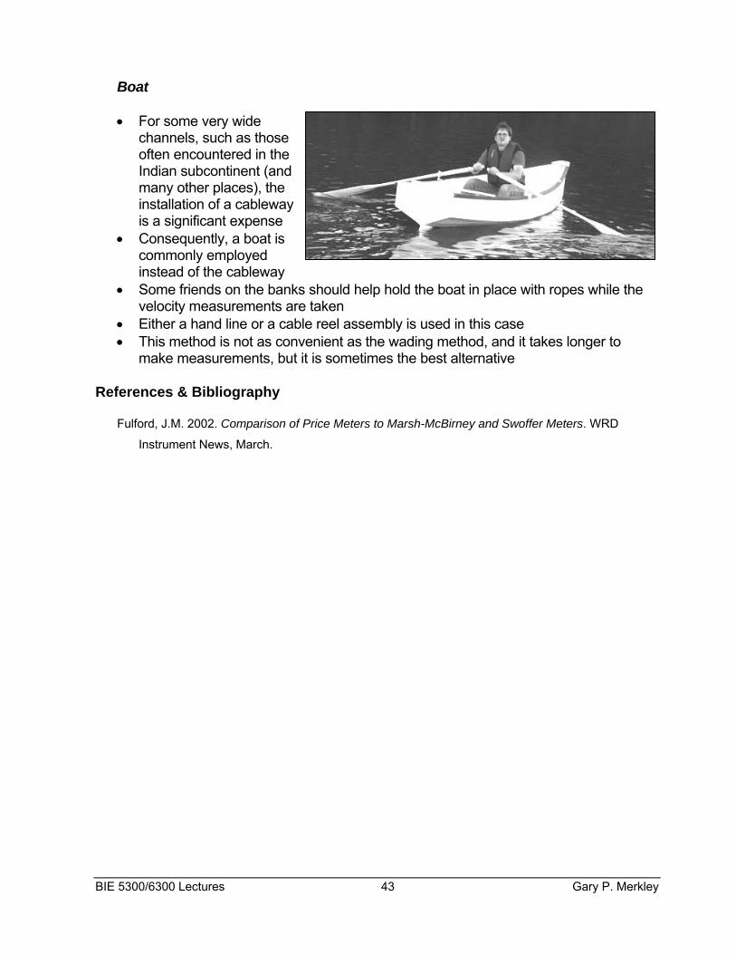
Boat
• For some very wide channels, such as those often encountered in the Indian subcontinent (and
any other places), the
m
• ently, a boat is
•
• akes longer to
Re e
Fulf
installation of a cableway is a significant expense Consequcommonly employed instead of the cableway Some friends on the banks should help hold the boat in place with ropes while thevelocity measurements are taken
• Either a hand line or a cable reel assembly is used in this case This method is not as convenient as the wading method, and it tmake measurements, but it is sometimes the best alternative
fer nces & Bibliography
ord, J.M. 2002. Comparison of Price Meters to Marsh-McBirney and Swoffer Meters. WRD
Instrument News, March.
BIE 5300/6300 Lectures 43 Gary P. Merkley

Gary P. Merkley 44 BIE 5300/6300 Lectures