Lecture 26: WED 18 MAR Magnetic fields Physics 2113 Jonathan Dowling “I’ll be back…. Aurora...
23
Lecture 26: WED 18 MAR Lecture 26: WED 18 MAR Magnetic fields Magnetic fields Physics 2113 Jonathan Dowling “I’ll be back…. Aurora Borealis
-
Upload
julia-weaver -
Category
Documents
-
view
220 -
download
0
Transcript of Lecture 26: WED 18 MAR Magnetic fields Physics 2113 Jonathan Dowling “I’ll be back…. Aurora...
Lecture 26: WED 18 Lecture 26: WED 18 MARMARMagnetic fields Magnetic fields
Physics 2113
Jonathan Dowling
“I’ll be back….
Aurora Borealis
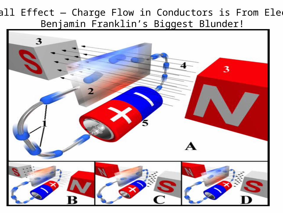
The Hall Effect — Charge Flow in Conductors is From Electrons:Benjamin Franklin’s Biggest Blunder!
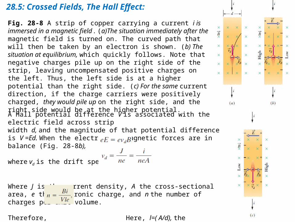
28.5: Crossed Fields, The Hall Effect:
Fig. 28-8 A strip of copper carrying a current i is immersed in a magnetic field . (a)The situation immediately after the magnetic field is turned on. The curved path that will then be taken by an electron is shown. (b) The situation at equilibrium, which quickly follows. Note that negative charges pile up on the right side of the strip, leaving uncompensated positive charges on the left. Thus, the left side is at a higher potential than the right side. (c) For the same current direction, if the charge carriers were positively charged, they would pile up on the right side, and the right side would be at the higher potential.
A Hall potential difference V is associated with the electric field across stripwidth d, and the magnitude of that potential difference is V =Ed. When the electric and magnetic forces are in balance (Fig. 28-8b),
where vd is the drift speed. But,
Where J is the current density, A the cross-sectional area, e the electronic charge, and n the number of charges per unit volume.
Therefore, Here, l=( A/d), the thickness of the strip.
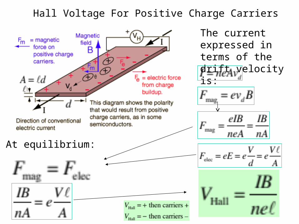
Hall Voltage For Positive Charge Carriers
The current expressed in terms of the drift velocity is:
At equilibrium:
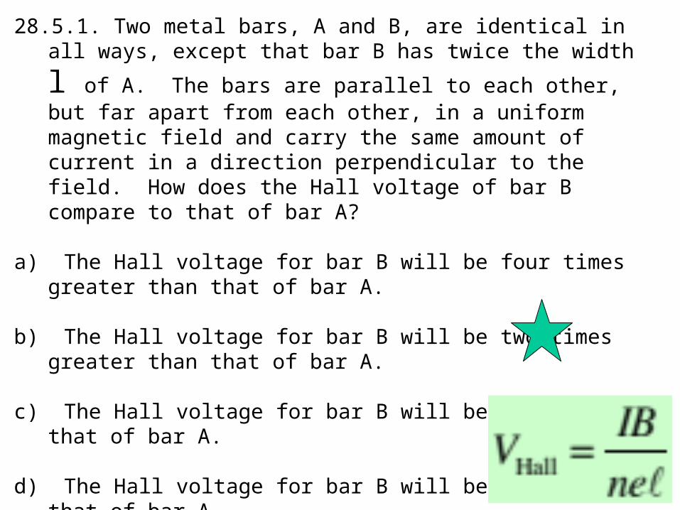
28.5.1. Two metal bars, A and B, are identical in all ways, except that bar B
has twice the width l of A. The bars are parallel to each other, but far apart from each other, in a uniform magnetic field and carry the same amount of current in a direction perpendicular to the field. How does the Hall voltage of bar B compare to that of bar A?
a) The Hall voltage for bar B will be four times greater than that of bar A.
b) The Hall voltage for bar B will be two times greater than that of bar A.
c) The Hall voltage for bar B will be the same as that of bar A.
d) The Hall voltage for bar B will be one-half that of bar A.
e) The Hall voltage for bar B will be one-fourth that of bar A.
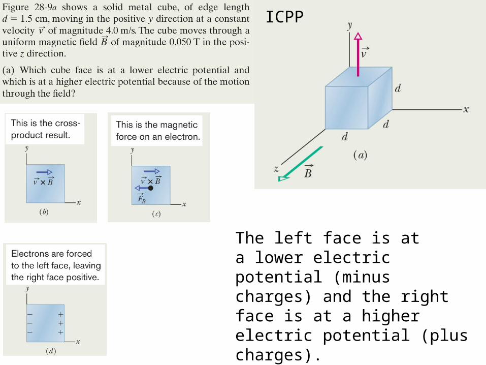
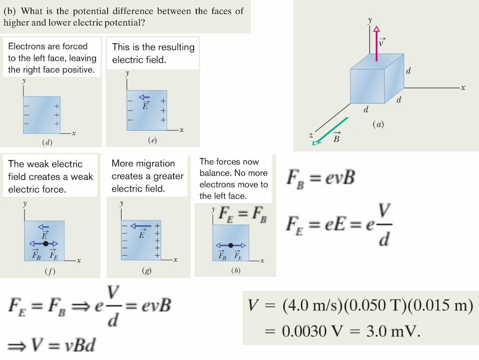
The left face is ata lower electric potential (minus charges) and the right face is at a higherelectric potential (plus charges).
ICPP
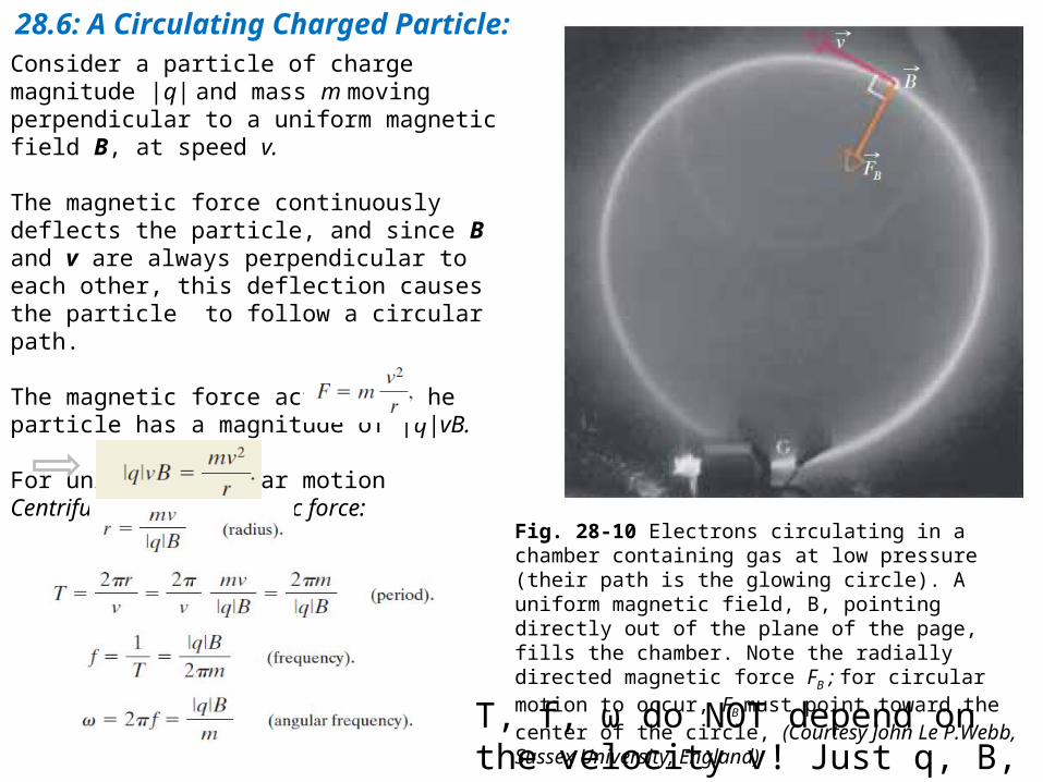
28.6: A Circulating Charged Particle:Consider a particle of charge magnitude |q| and mass m moving perpendicular to a uniform magnetic field B, at speed v.
The magnetic force continuously deflects the particle, and since B and v are always perpendicular to each other, this deflection causes the particle to follow a circular path.
The magnetic force acting on the particle has a magnitude of |q|vB.
For uniform circular motionCentrifugal force = Magnetic force:
Fig. 28-10 Electrons circulating in a chamber containing gas at low pressure (their path is the glowing circle). A uniform magnetic field, B, pointing directly out of the plane of the page, fills the chamber. Note the radially directed magnetic force FB ; for circular motion to occur, FB must point toward the center of the circle, (Courtesy John Le P.Webb, Sussex University, England)
T, f, ω do NOT depend on the velocity v! Just q, B, and m.
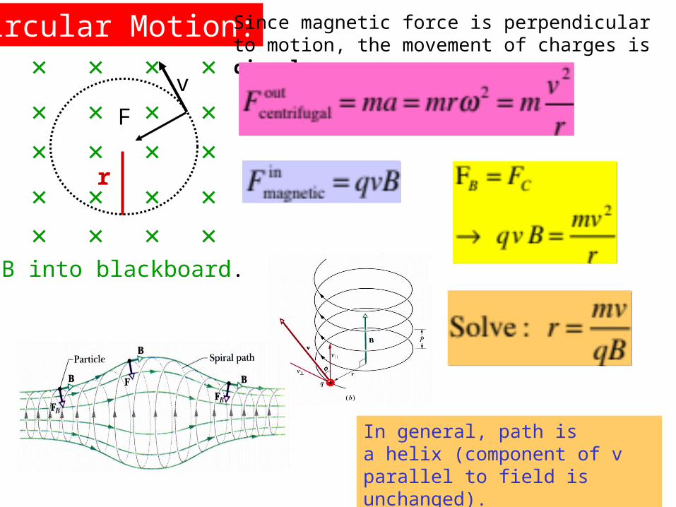
Circular Motion: Since magnetic force is perpendicular to motion, the movement of charges is circular.
In general, path is a helix (component of v parallel to field is unchanged).
In general, path is a helix (component of v parallel to field is unchanged).
B into blackboard.
v
F
r
B into blackboard.
v
F
r
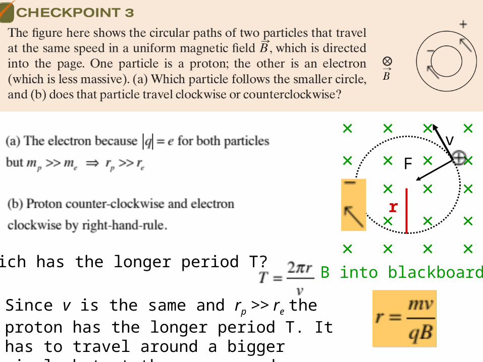
Which has the longer period T?
Since v is the same and rp >> re the proton has the longer period T. It has to travel around a bigger circle but at the same speed.

.
.electron
C
r
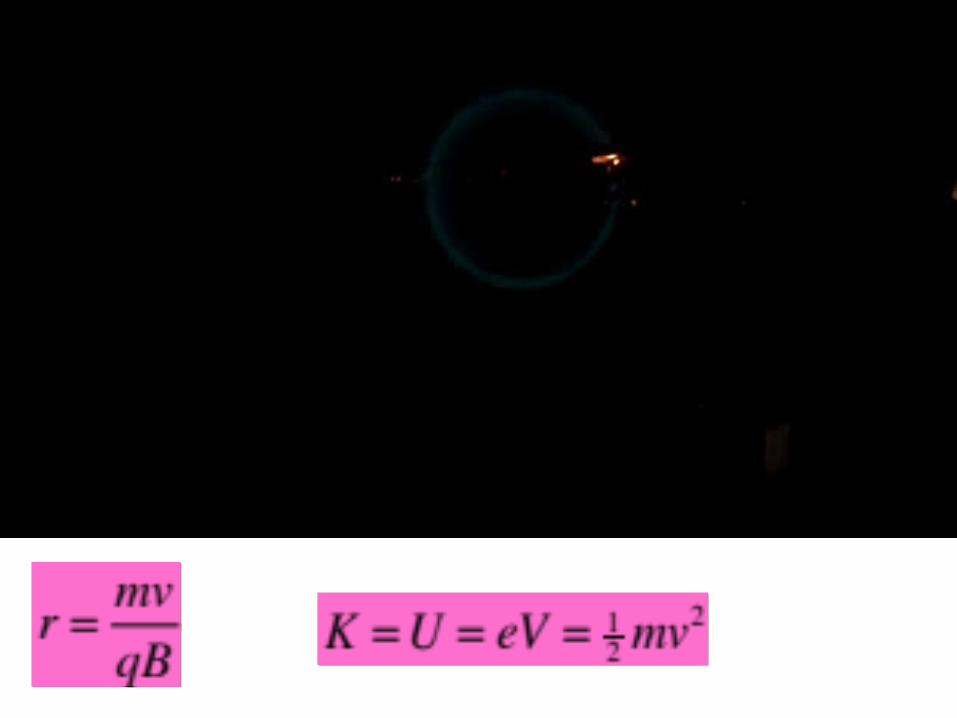
Radius of Circlcular OrbitRadius of Circlcular Orbit
Angular Frequency:Independent of v Angular Frequency:Independent of v
Period of Orbit:Independent of v Period of Orbit:Independent of v
Orbital Frequency:Independent of v Orbital Frequency:Independent of v
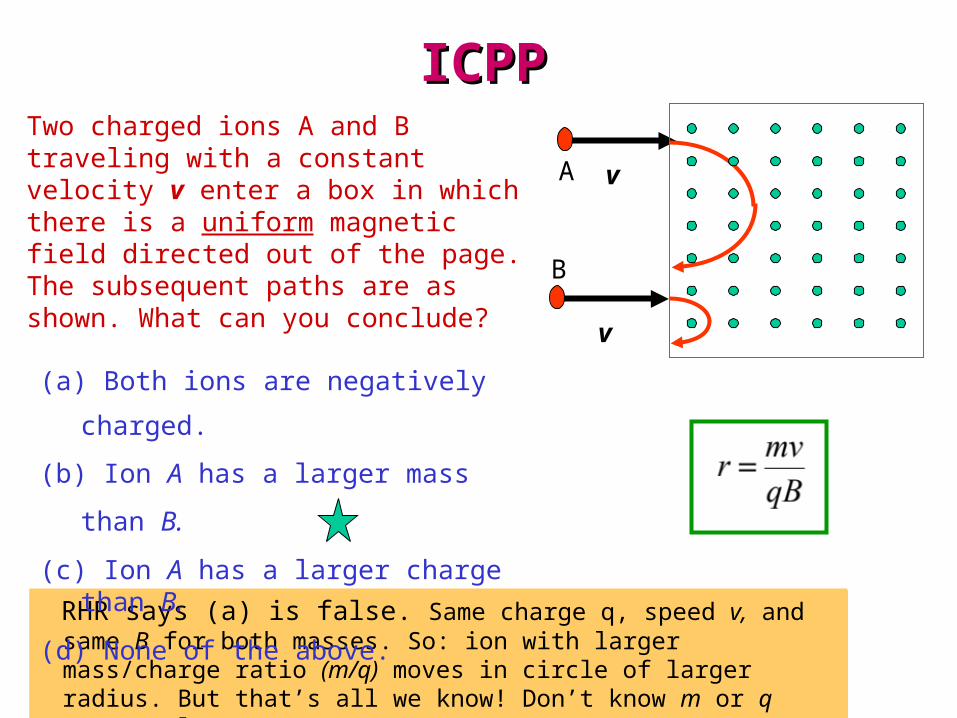
ICPPICPPTwo charged ions A and B traveling with a constant velocity v enter a box in which there is a uniform magnetic field directed out of the page. The subsequent paths are as shown. What can you conclude?
RHR says (a) is false. Same charge q, speed v, and same B for both masses. So: ion with larger mass/charge ratio (m/q) moves in circle of larger radius. But that’s all we know! Don’t know m or q separately.
RHR says (a) is false. Same charge q, speed v, and same B for both masses. So: ion with larger mass/charge ratio (m/q) moves in circle of larger radius. But that’s all we know! Don’t know m or q separately.
(a) Both ions are negatively
charged.
(b) Ion A has a larger mass than B.
(c) Ion A has a larger charge than B.
(d) None of the above.
v
v
A
B
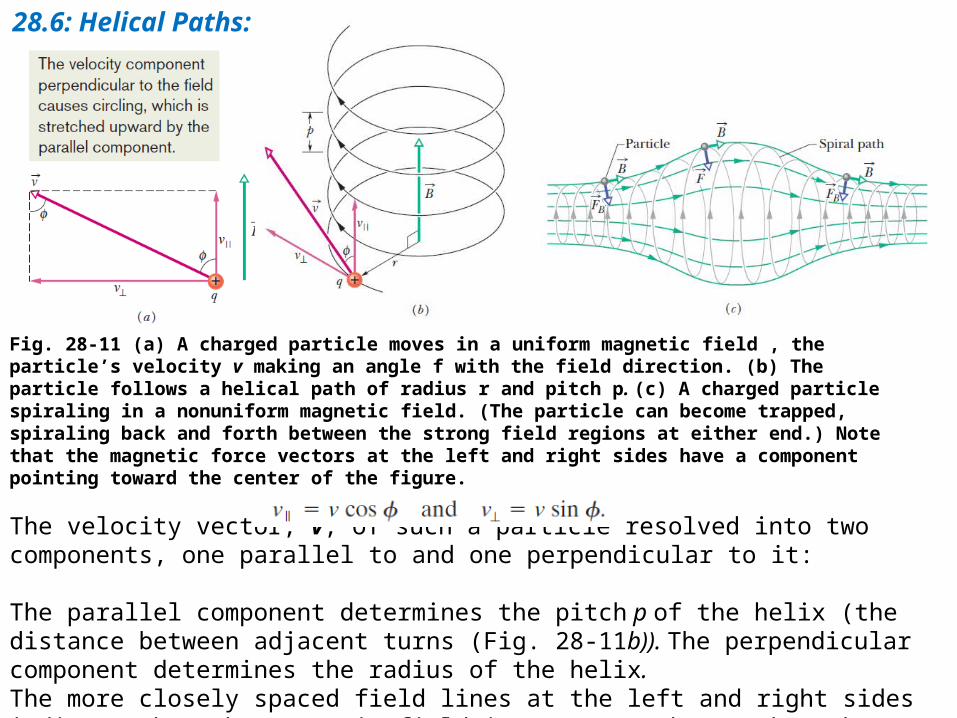
28.6: Helical Paths:
Fig. 28-11 (a) A charged particle moves in a uniform magnetic field , the particle’s velocity v making an angle f with the field direction. (b) The particle follows a helical path of radius r and pitch p. (c) A charged particle spiraling in a nonuniform magnetic field. (The particle can become trapped, spiraling back and forth between the strong field regions at either end.) Note that the magnetic force vectors at the left and right sides have a component pointing toward the center of the figure.
The velocity vector, v, of such a particle resolved into two components, one parallel to and one perpendicular to it:
The parallel component determines the pitch p of the helix (the distance between adjacent turns (Fig. 28-11b)). The perpendicular component determines the radius of the helix. The more closely spaced field lines at the left and right sides indicate that the magnetic field is stronger there. When the field at an end is strong enough, the particle “reflects” from that end. If the particle reflects from both ends, it is said to be trapped in a magnetic bottle.
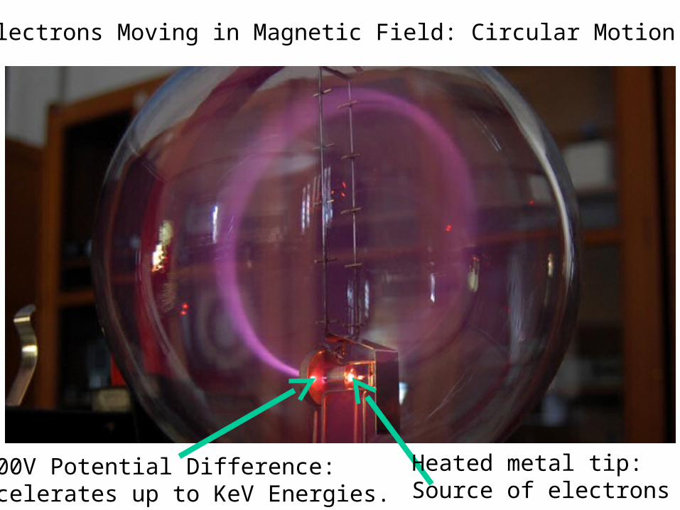
Electrons Moving in Magnetic Field: Circular Motion
Heated metal tip:Source of electrons
1000V Potential Difference:Accelerates up to KeV Energies.
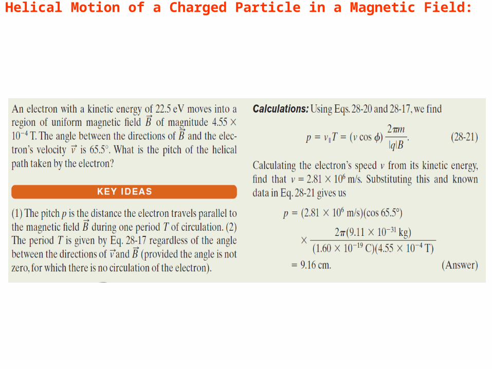
Example, Helical Motion of a Charged Particle in a Magnetic Field:
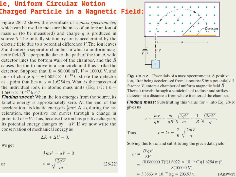
Example, Uniform Circular Motion of a Charged Particle in a Magnetic Field:
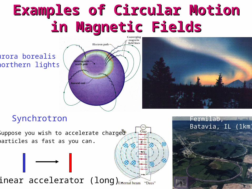
Aurora borealis(northern lights)
Synchrotron
Linear accelerator (long).
Fermilab,Batavia, IL (1km)
Suppose you wish to accelerate chargedparticles as fast as you can.
Examples of Circular Motion in Examples of Circular Motion in Magnetic FieldsMagnetic Fields

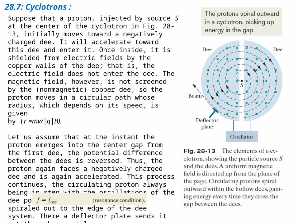
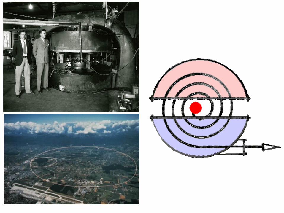
28.7: Cyclotrons :Suppose that a proton, injected by source S at the center of the cyclotron in Fig. 28-13, initially moves toward a negatively charged dee. It will accelerate toward this dee and enter it. Once inside, it is shielded from electric fields by the copper walls of the dee; that is, the electric field does not enter the dee. The magnetic field, however, is not screened by the (nonmagnetic) copper dee, so the proton moves in a circular path whose radius, which depends on its speed, is givenby (r =mv/|q|B).
Let us assume that at the instant the proton emerges into the center gap from the first dee, the potential difference between the dees is reversed. Thus, the proton again faces a negatively charged dee and is again accelerated. This process continues, the circulating proton always being in step with the oscillations of the dee potential, until the proton has spiraled out to the edge of the dee system. There a deflector plate sends it out through a portal.
The frequency f at which the proton circulates in the magnetic field (and that does not depend on its speed) must be equal to the fixed frequency fosc of the electrical oscillator:
28.7: The Proton Synchrotron :
At proton energies above 50 MeV, the conventional cyclotron begins to fail. Also, for a 500 GeV proton in a magnetic field of 1.5 T, the path radius is 1.1 km. The corresponding magnet for a conventional cyclotron of the proper size would be impossibly expensive.
In the proton synchrotron the magnetic field B, and the oscillator frequency fosc, instead of having fixed values as in the conventional cyclotron, are made to vary with time during the accelerating cycle.
When this is done properly, (1)the frequency of the circulating protons remains in step with the oscillator at all times, and (2)the protons follow a circular—not a spiral—path. Thus, the magnet need extend only along that circular path, not over some 4x10⁶ m2. The circular path, however, still must be large if high energies are to be achieved.
The proton synchrotron at the Fermi National Accelerator Laboratory (Fermilab) in Illinois has a circumference of 6.3 km and can produce protons with energies of about 1 TeV ( 1012 eV).