Lecture 20. Wind Lidar (2) -...
16
Lecture 20. Wind Lidar (2) Vector Wind Determination Vector wind determination Ideal vector wind measurement VAD and DBS technique for vector wind Coherent versus incoherent Detection Doppler wind lidar techniques Summary
Transcript of Lecture 20. Wind Lidar (2) -...
Lecture 20. Wind Lidar (2)Vector Wind Determination
Vector wind determination
Ideal vector wind measurement
VAD and DBS technique for vector wind
Coherent versus incoherent Detection
Doppler wind lidar techniques
Summary

Vector Wind Velocity Determination Vector (u, v, w) wind velocity estimates require radial velocity
measurements from at least three independent Line-Of-Sight (LOS).
Ideally: to obtain a vector wind at a given point in space is to view thesame point from 3 or more LOS directions
(1) Three or more lidar systems are required to do so
(2) When assuming W = 0, two lidar systems can do it.
Practically: under a necessary assumption of horizontal homogeneity ofthe wind field over the sensed volume, lidar beam scanning techniques canbe used to determine the vector wind velocity.
Two main techniques for this scanning -
(1) the Velocity-Azimuth-Display (VAD) technique:
-- conical scan lidar beam at a fixed elevation angle
(2) the Doppler-Beam-Swinging (DBS) techniques:
-- pointing lidar beam to vertical, tilted east, and tilted north

Ideal Vector Wind Measurement
12
3
EW
S
N
A possibility is to detect the same volume from Table Mountain andFort Collins simultaneously for wind and gravity wave study.
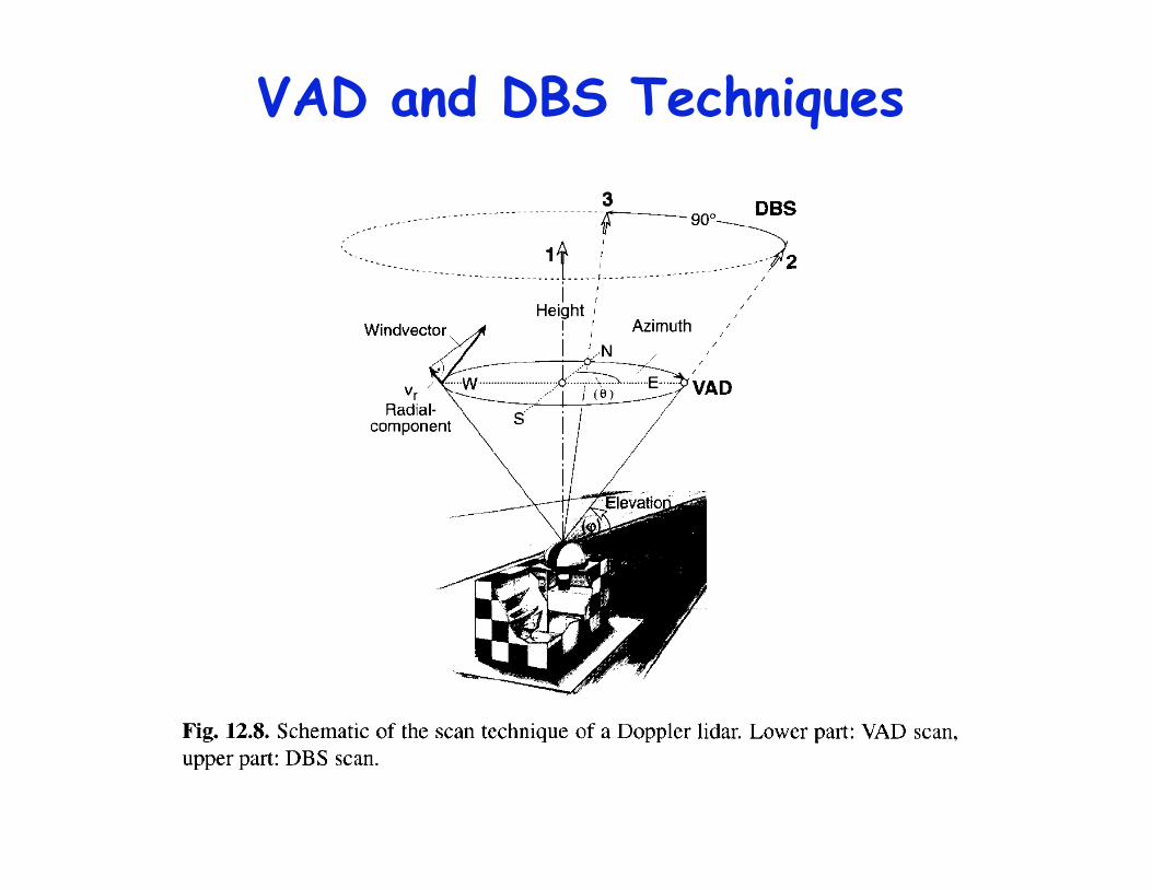
VAD and DBS Techniques

VAD and DBS Techniques
VectorWind = (u,v,w) = ( bsin max /cos , bcos max /cos , a /sin )
Fit the scanning results with
Radial velocity is given byVAD
For DBS technique, the three components are obtained as
u = (Vr2 Vr1 sin ) /cos
v = (Vr3 Vr1 sin ) /cos
w = Vr1
Vr1, Vr2, Vr3 are the vertical, east, and north radial velocities

VAD Technique for Vector Wind Velocity-Azimuth-Display (VAD) technique: conical scan lidar beam at a
fixed elevation angle
For groundbased lidar, we define positive u, v, w as the wind blowingtowards east, north, and upward, and positive radial wind VR as the windblowing away from the lidar.
u sin cos
v cos cos
w sin
Radial velocity VR consists ofcomponents from u, v, and w:
VR = u sin cos + v cos cos +w sin
Zonal wind contribution
Meridional contribution
Vertical contribution
N = 0o , E = 90o , S =180o , W = 270o

VectorWind = (u,v,w) = (bsin max /cos ,bcos max /cos ,a /sin )
Azimuth Angle
Rad
ial Vel
ocity
VR
VR = u sin cos + v cos cos +w sin
For VAD scan, elevation angle is fixed (constant) and known, azimuthangle is varied but also known. VR is measured, so the three unknownparameters u, v, and w can be derived directly from fitting the data withabove equation.
Another approach is to fit the scan data with the following equation:
VR = a + bcos( max ) = bsin max sin + bcos max cos + a
where a is offset, b is amplitude, and max is the phase shift

DBS Technique for Vector Wind
u = (VRE VRZ cos ) /sin
v = (VRN VRZ cos ) /sin
w =VRZ
VRZ, VRE, VRN are the vertical, tilted east, and tilted north radial velocities
Doppler-Beam-Swinging (DBS) techniques: pointing lidar beam tovertical, tilted east, and tilted north.
VRE = u sin +w cos
VRN = v sin +w cos
VRZ = w
is the off-zenith angle

Modified DBS Technique Pointing lidar beam to vertical, tilted north, tilted east, tilted
south, and tilted west directions (ZNEZSW).
VRE = u sin +w cos
VRW = u sin +w cos
VRN = v sin +w cos
VRS = v sin +w cos
VRZ = w
is the off-zenith angle
u = (VRE VRW ) /sin /2
v = (VRN VRS ) /sin /2
w =VRZ
VR > 0, w > 0, u > 0, v > 0 for wind towards away, upward, east, and north
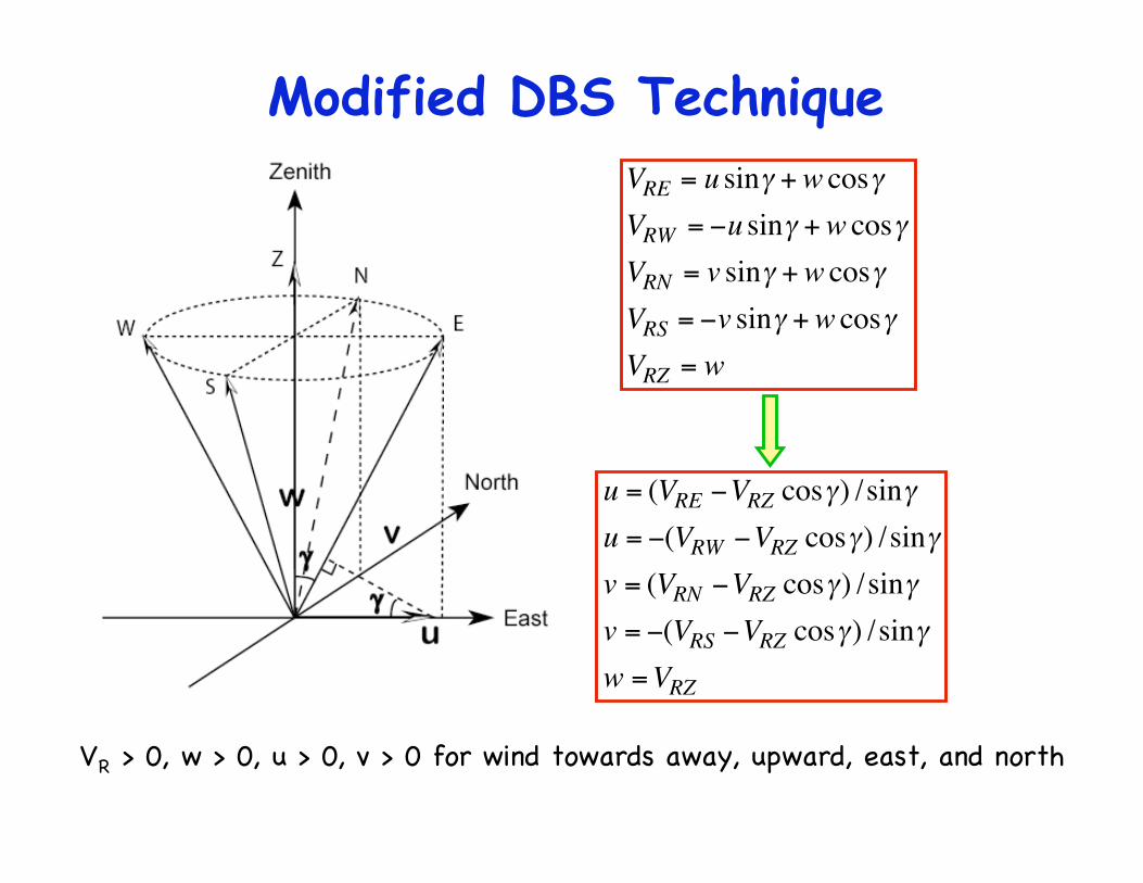
Modified DBS Technique
VRE = u sin +w cos
VRW = u sin +w cos
VRN = v sin +w cos
VRS = v sin +w cos
VRZ = w
VR > 0, w > 0, u > 0, v > 0 for wind towards away, upward, east, and north
u = (VRE VRZ cos ) /sin
u = (VRW VRZ cos ) /sin
v = (VRN VRZ cos ) /sin
v = (VRS VRZ cos ) /sin
w =VRZ

Modified DBS TechniqueVRE = u sin +w cos
VRW = u sin +w cos
VRN = v sin +w cos
VRS = v sin +w cos
VRZ = w
In the middle atmosphere, w is less than 1 m/s while the measurementprecision of radial velocity is about 1 m/s. So it is reasonable to ignore thecontribution from vertical wind to off-zenith radial wind.
u =VRE /sin
u = VRW /sin
v =VRN /sin
v = VRS /sin
w =VRZ
Coherent vs Incoherent Doppler Wind Doppler wind technique relies on the well-know Doppler effect.
The radial (LOS) velocity is inferred from the measured Dopplerfrequency shift. Thus, some spectral analysis must be used tomeasure the Doppler frequency shift - either coherent detection tomeasure the beat frequency or incoherent detection to measurethe spectrum of return signals.
Coherent (heterodyne) Detection Doppler Wind Lidar (CDL) is tomeasure the frequency of the beat signal obtained by opticallymixing the return signal with the cw local oscillator. Thus, both thelocal oscillator and the return signal need to have narrowbandwidths in order to have sufficient coherent length.
Therefore, coherent detection lidar relies on the aerosolscattering with very narrow Doppler broadening, thus only applyingto the atmospheric regions with sufficient amount of aerosols.
Molecular scattering in atmosphere has the Doppler broadeningwith more than 1GHz width - not suitable for coherent detection.

Wavelength Considerations for CDL
In principle, Doppler wind lidar can choose random laser wavelength, asthere is no specific resonance absorption wavelength required.
However, because the aerosol (Mie) scattering is better suited forfrequency analysis in the coherent detection lidar than the molecular(Rayleigh) scattering, the choice of the wavelength to be used will dependon the expected magnitude of the return signal and the expected ratio ofaerosol-to-molecular backscatter.
The molecular scattering cross-section is proportional to -4, and theaerosol signal is proportional to between -2 and +1, depending on thewavelength and particle size/shape. Thus, even if the aerosol returndecreases with an increase wavelength, the molecular backgrounddecreases much faster so the aerosol-to-molecular backscatter ratio getsmore favorable.
Therefore, longer wavelength is desirable to minimize the influence frommolecular (Rayleigh) scattering. Usually coherent Doppler lidar uses laserwavelength between 1-11 μm.

Direct Detection Doppler Wind Lidar Direction Detection Doppler Wind Lidar (DDL) uses incoherent
detection to measure the spectrum of return signals - one kind ofDoppler wind technique with very bright future potential.
This is because DDL can exploit aerosol scattering, molecularscattering, and/or resonance fluorescence, thus possessing thecapability to measure wind from ground to upper atmosphere.
There are several different ways to do spectral analysis for DDL(1) Resonance fluorescence Doppler lidar: use the atmospheric atomic ormolecular absorption lines as the frequency analyzer / discriminator
(2) Direct detection Doppler lidar based on molecular-absorption-edge-filter: e.g., iodine (I2) vapor filter, Na or K magneto-optic filter
(3) Direct detection Doppler lidar based on optical interferometer edge-filter: e.g., Fabry-Perot etalon transmission edge
(4) Direct detection Doppler lidar based on fringe pattern imaging of anoptical interferometer: e.g., FPI imaging

Wavelength Considerations for DDL For resonance fluorescence Doppler lidar, certain specific frequencies
are required to match the atomic absorption lines. For example, 589 nmfor Na, 770 nm for K, and 372 nm for Fe.
For molecular absorption edge filter, it also depends on the availablemolecular absorption lines. For example, iodine has absorption in the visibleand near IR, thus 532 nm is currently popular, also owing to availableNd:YAG laser technology.
For interferometer based (both edge-filter and fringe imaging) DDL, inprinciple you can choose any wavelength (as long as atmospherictransmission is reasonably high) because the etalon of the interferometercan be coated to any wavelength.
If molecular scattering is used, shorter wavelength is preferred to havemuch strong molecular (Rayleigh) scattering, because of scatter -4.
Since Doppler broadening of molecular scattering is in the order of afew GHz, the spectral bandwidth of the laser pulse is not necessary to beas narrow as the coherent Doppler lidar. Instead, bandwidth in the orderof 100 MHz would be good for DDL. This also allows shorter duration pulseto be used in DDL systems to improve range resolution.
Summary Wind is a vector consisting of three components: (u, v, w)
corresponding to zonal, meridional, and vertical winds.
Since Doppler wind technique measures the velocity along thelidar beam, it needs radial velocity measurements from at leastthree independent Line-Of-Sight (LOS).
Ideally, we want to point 3 lidar beams from three differentdirections (e.g., zenith, south, and west) to a given point in space.
Practically, under some assumption of horizontal homogeneityof the wind field over the sensed volume, scanning lidartechniques can be used to determine the vector wind. Two mainscanning techniques are the Velocity-Azimuth-Display (VAD)technique and the Doppler-Beam-Swinging (DBS) technique.
Considerations of different wavelength requirements forcoherent and incoherent detection Doppler lidars are discussed.