
Lecture #11: Introduction to Fiber-reinforced Composite ... · PDF file2/15/2016 Lecture #11...
43
2/15/2016 1 1 Lecture #11 – Fall 2015 1 D. Mohr by Dirk Mohr ETH Zurich, Department of Mechanical and Process Engineering, Chair of Computational Modeling of Materials in Manufacturing Lecture #11: • Introduction to Fiber-reinforced Composite Materials © 2015
Transcript of Lecture #11: Introduction to Fiber-reinforced Composite ... · PDF file2/15/2016 Lecture #11...

2/15/2016 1 1Lecture #11 – Fall 2015 1D. Mohr
151-0735: Dynamic behavior of materials and structures
by Dirk Mohr
ETH Zurich, Department of Mechanical and Process Engineering,
Chair of Computational Modeling of Materials in Manufacturing
Lecture #11:
• Introduction to Fiber-reinforced Composite Materials
© 2015
2/15/2016 2 2Lecture #11 – Fall 2015 2D. Mohr
151-0735: Dynamic behavior of materials and structures
Composite Materials
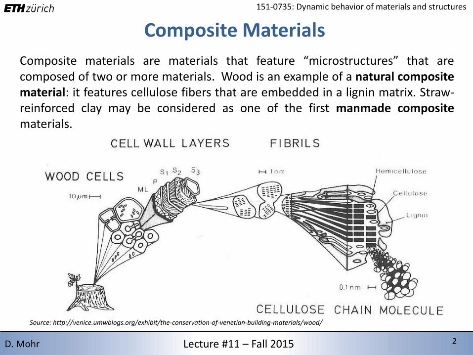
Composite materials are materials that feature “microstructures” that arecomposed of two or more materials. Wood is an example of a natural compositematerial: it features cellulose fibers that are embedded in a lignin matrix. Straw-reinforced clay may be considered as one of the first manmade compositematerials.
Source: http://venice.umwblogs.org/exhibit/the-conservation-of-venetian-building-materials/wood/
2/15/2016 3 3Lecture #11 – Fall 2015 3D. Mohr
151-0735: Dynamic behavior of materials and structures
Fiber-reinforced Composites
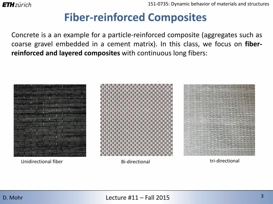
Concrete is a an example for a particle-reinforced composite (aggregates such ascoarse gravel embedded in a cement matrix). In this class, we focus on fiber-reinforced and layered composites with continuous long fibers:
Unidirectional fiber Bi-directional tri-directional
2/15/2016 4 4Lecture #11 – Fall 2015 4D. Mohr
151-0735: Dynamic behavior of materials and structures
0
200
400
600
800
1000
0 2 4 6 8 10
Mo
du
lus
[GP
a]
Density [g/cm3]
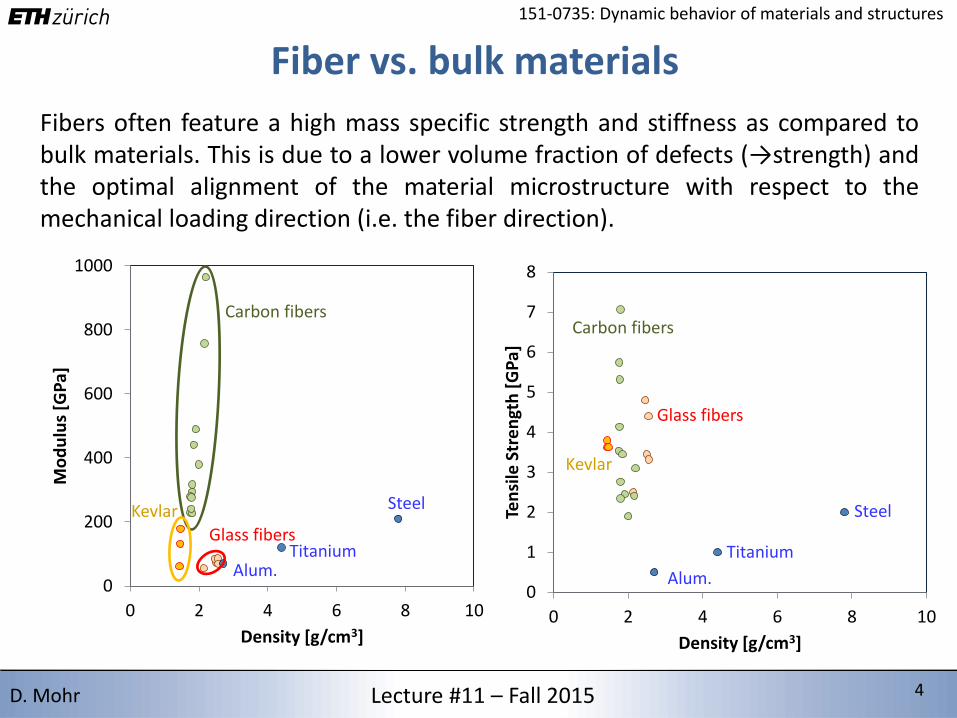
Fiber vs. bulk materials
Fibers often feature a high mass specific strength and stiffness as compared tobulk materials. This is due to a lower volume fraction of defects (→strength) andthe optimal alignment of the material microstructure with respect to themechanical loading direction (i.e. the fiber direction).
Carbon fibers
Kevlar
Glass fibers
Alum.
Steel
0
1
2
3
4
5
6
7
8
0 2 4 6 8 10
Ten
sile
Str
en
gth
[G
Pa]
Density [g/cm3]
Titanium
Alum.
Steel
Titanium
Kevlar
Glass fibers
Carbon fibers
2/15/2016 5 5Lecture #11 – Fall 2015 5D. Mohr
151-0735: Dynamic behavior of materials and structures
Common fibersReinforcements fibers typically are of 10-100mm diameter. E-glass fibers are thelow-cost reinforcement choice for composite materials (~1.5 CHF/kg, which is50% higher than the price for steel). They are made from amorphous glass (blendof sand, limestone and other oxidic compounds). The particular feature of E-glassfibers is a low area density of defects on the fiber surface which results in atensile strength of up to 3 GPa. Other type of glass fibers include C-glass(corrosion resistant), S-glass (high strength), D-glass (dielectric) and A-glass(alkaline resistant).
Carbon fibers are widely used in aerospace engineering. Their stiffness can be upto 10 times higher than that of glass fibers, and their price per kg can be 20 to500 times higher. High strength carbon fibers reach stress levels of up to 7 GPa.Depending on the raw material and manufacturing process, their stiffness canvary from 200 to 1000 GPa.
Carbon nanotubes also belong to the class of carbon fiber materials. They feature a cylindrical atomicstructure (1nm diameter). The modulus and strength of defect-free nanotubes may reach values ashigh as 1500 GPa and 200 GPa, respectively. At this stage, the estimated costs of about 500’000CHF/kg prohibits their wide-spread use in industrial applications.
2/15/2016 6 6Lecture #11 – Fall 2015 6D. Mohr
151-0735: Dynamic behavior of materials and structures
Textile design
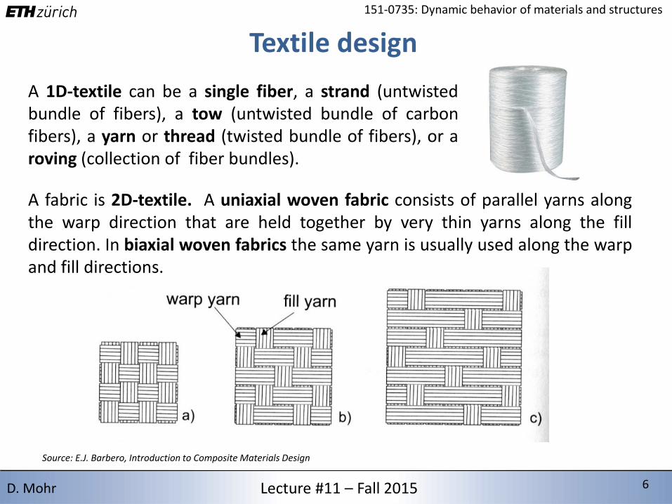
A 1D-textile can be a single fiber, a strand (untwistedbundle of fibers), a tow (untwisted bundle of carbonfibers), a yarn or thread (twisted bundle of fibers), or aroving (collection of fiber bundles).
Source: E.J. Barbero, Introduction to Composite Materials Design
A fabric is 2D-textile. A uniaxial woven fabric consists of parallel yarns alongthe warp direction that are held together by very thin yarns along the filldirection. In biaxial woven fabrics the same yarn is usually used along the warpand fill directions.
2/15/2016 7 7Lecture #11 – Fall 2015 7D. Mohr
151-0735: Dynamic behavior of materials and structures
Matrix materials
The matrix material holds together the fibers and contributes to the stiffnessand strength of the composite material. It also provides many non-mechanicalfunctions (heat and electrical conductivity, appearance, corrosion resistance,fire resistance, etc.).
Source: E.J. Barbero, Introduction to Composite Materials Design
Matrix materials can be subdivided into two categories: thermoplastics andthermoset matrices, i.e. polymer matrices that solidify through irreversiblecross-linking at the molecular level, such as:
• Polyester resins (high performance/cost ratio, cross-linking at room temperature through use of
accelerators, fumes can be toxic)
• Vinyl ester resins (high chemical resistance)
• Epoxy resins (often toughed through additives, excellent electrical insulation, tensile strength of
up to 100 MPa, Young’s modulus of 1 to 4 GPa, density about 1.2g/cm3)
• Phenolic resins (low flammability and smoke production)
2/15/2016 8 8Lecture #11 – Fall 2015 8D. Mohr
151-0735: Dynamic behavior of materials and structures
Laminae and laminate
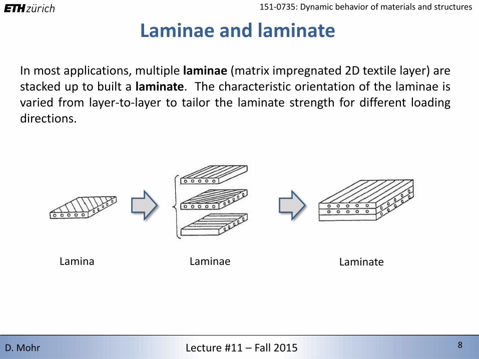
In most applications, multiple laminae (matrix impregnated 2D textile layer) arestacked up to built a laminate. The characteristic orientation of the laminae isvaried from layer-to-layer to tailor the laminate strength for different loadingdirections.
Lamina Laminae Laminate
2/15/2016 9 9Lecture #11 – Fall 2015 9D. Mohr
151-0735: Dynamic behavior of materials and structures
Wet lay-up process
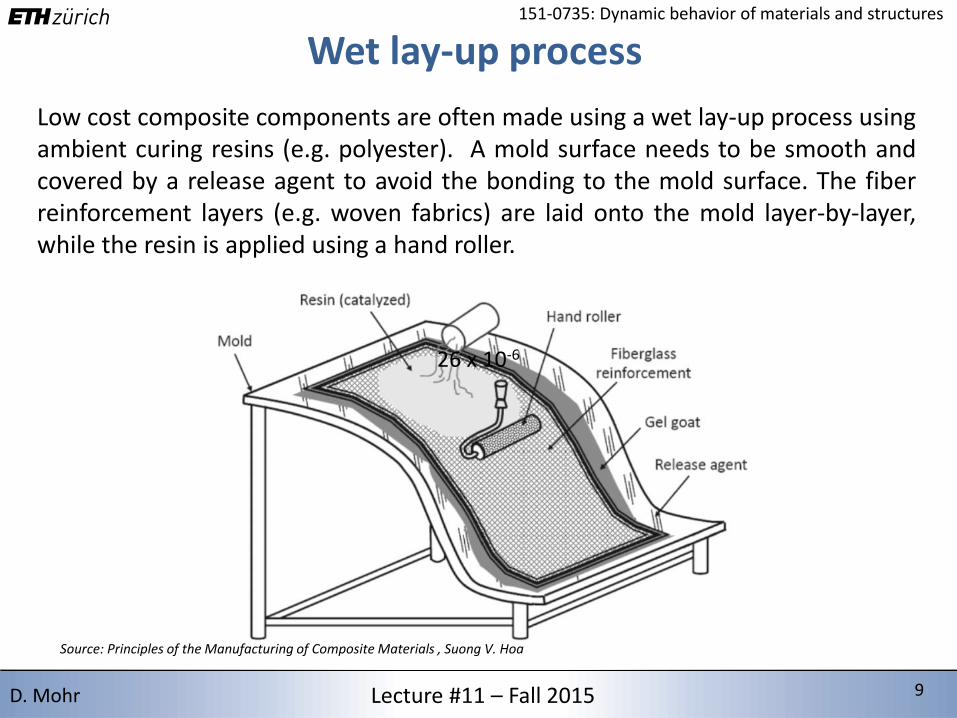
Low cost composite components are often made using a wet lay-up process usingambient curing resins (e.g. polyester). A mold surface needs to be smooth andcovered by a release agent to avoid the bonding to the mold surface. The fiberreinforcement layers (e.g. woven fabrics) are laid onto the mold layer-by-layer,while the resin is applied using a hand roller.
26 x 10-6
Source: Principles of the Manufacturing of Composite Materials , Suong V. Hoa
2/15/2016 10 10Lecture #11 – Fall 2015 10D. Mohr
151-0735: Dynamic behavior of materials and structures
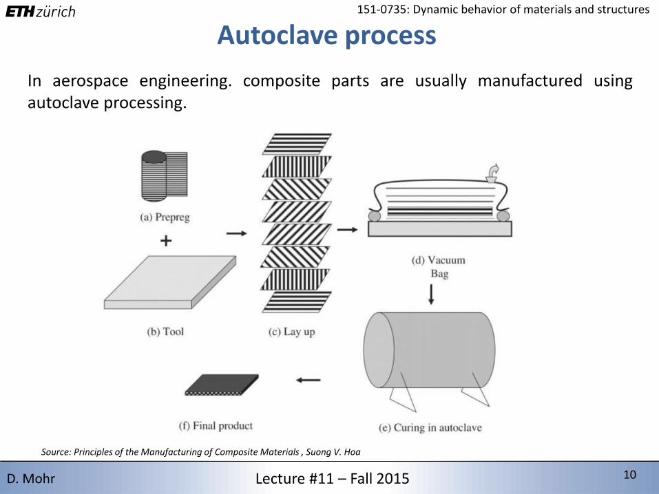
Autoclave process
In aerospace engineering. composite parts are usually manufactured usingautoclave processing.
Source: Principles of the Manufacturing of Composite Materials , Suong V. Hoa
2/15/2016 11 11Lecture #11 – Fall 2015 11D. Mohr
151-0735: Dynamic behavior of materials and structures
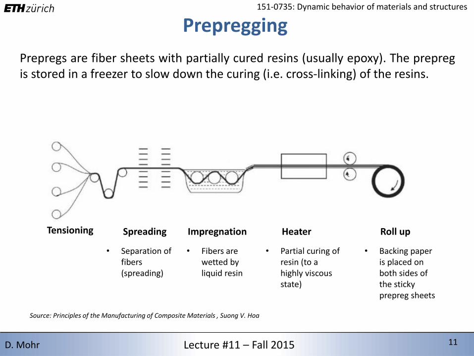
Prepregging
Prepregs are fiber sheets with partially cured resins (usually epoxy). The prepregis stored in a freezer to slow down the curing (i.e. cross-linking) of the resins.
Source: Principles of the Manufacturing of Composite Materials , Suong V. Hoa
Spreading
• Separation of fibers (spreading)
Impregnation
• Fibers are wetted by liquid resin
Heater
• Partial curing of resin (to a highly viscous state)
Roll up
• Backing paper is placed on both sides of the sticky prepreg sheets
Tensioning
2/15/2016 12 12Lecture #11 – Fall 2015 12D. Mohr
151-0735: Dynamic behavior of materials and structures
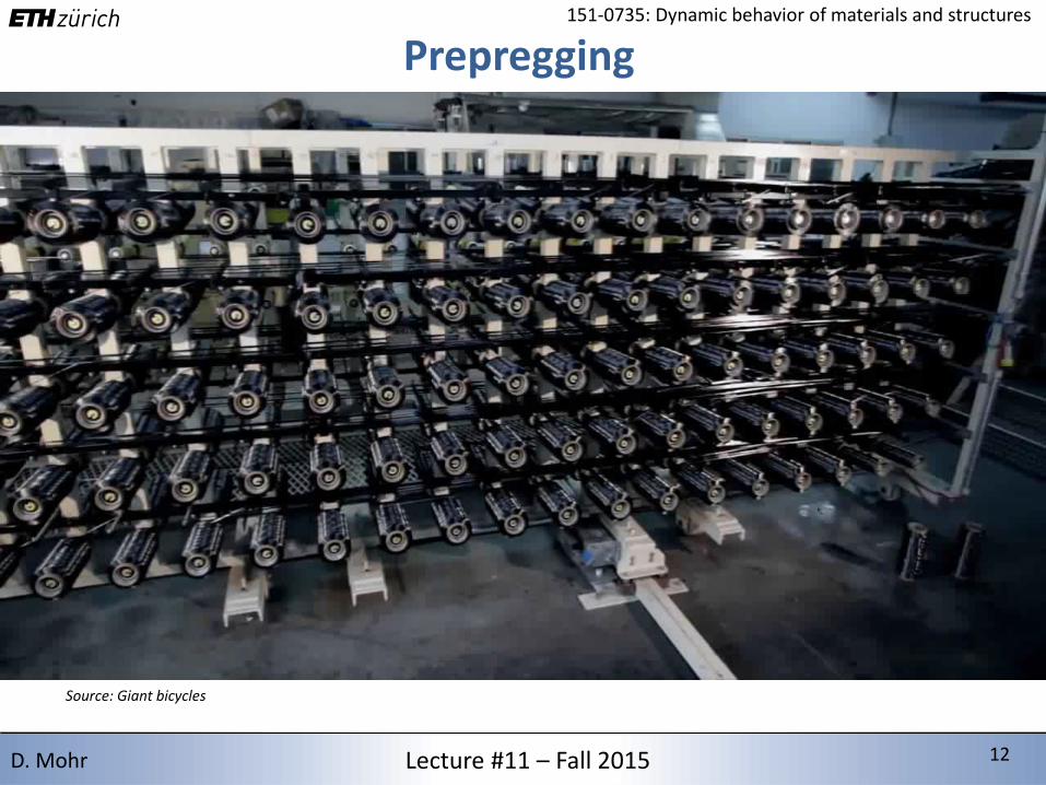
Prepregging
Source: Giant bicycles
2/15/2016 13 13Lecture #11 – Fall 2015 13D. Mohr
151-0735: Dynamic behavior of materials and structures
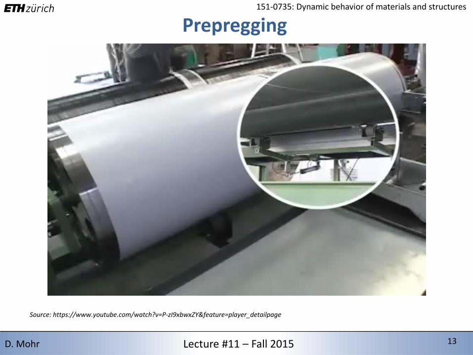
Prepregging
Source: https://www.youtube.com/watch?v=P-zI9xbwxZY&feature=player_detailpage

2/15/2016 14 14Lecture #11 – Fall 2015 14D. Mohr
151-0735: Dynamic behavior of materials and structures
Prepregging
Source: https://www.youtube.com/watch?v=P-zI9xbwxZY&feature=player_detailpage
2/15/2016 15 15Lecture #11 – Fall 2015 15D. Mohr
151-0735: Dynamic behavior of materials and structures
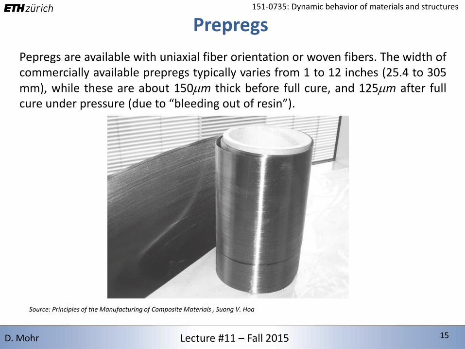
Prepregs
Pepregs are available with uniaxial fiber orientation or woven fibers. The width ofcommercially available prepregs typically varies from 1 to 12 inches (25.4 to 305mm), while these are about 150mm thick before full cure, and 125mm after fullcure under pressure (due to “bleeding out of resin”).
Source: Principles of the Manufacturing of Composite Materials , Suong V. Hoa
2/15/2016 16 16Lecture #11 – Fall 2015 16D. Mohr
151-0735: Dynamic behavior of materials and structures
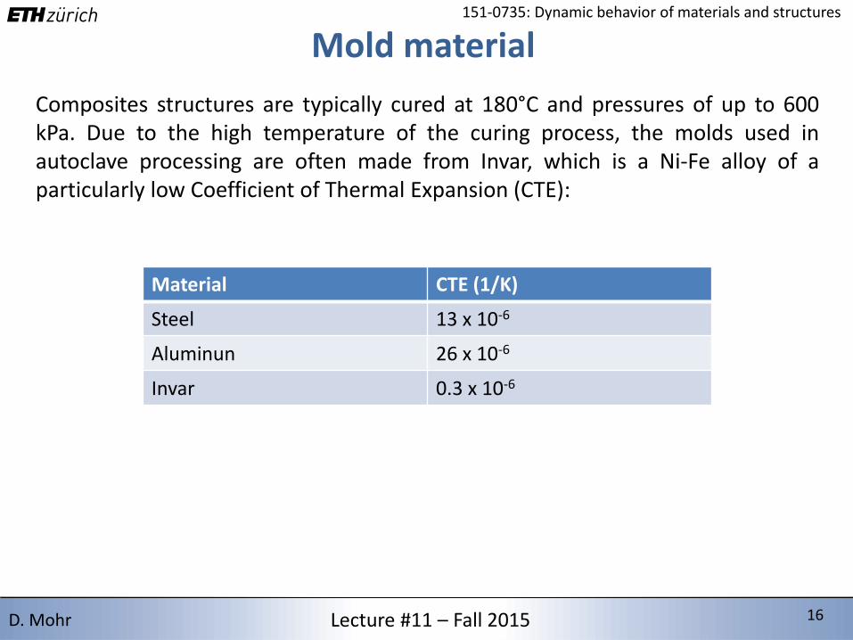
Mold material
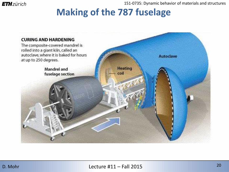
Composites structures are typically cured at 180°C and pressures of up to 600kPa. Due to the high temperature of the curing process, the molds used inautoclave processing are often made from Invar, which is a Ni-Fe alloy of aparticularly low Coefficient of Thermal Expansion (CTE):
Material CTE (1/K)
Steel 13 x 10-6
Aluminun 26 x 10-6
Invar 0.3 x 10⁻⁶
2/15/2016 17 17Lecture #11 – Fall 2015 17D. Mohr
151-0735: Dynamic behavior of materials and structures
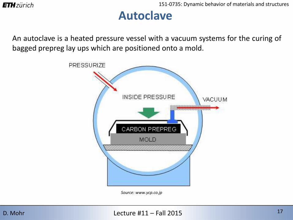
Autoclave
An autoclave is a heated pressure vessel with a vacuum systems for the curing ofbagged prepreg lay ups which are positioned onto a mold.
Source: www.ycp.co.jp

2/15/2016 18 18Lecture #11 – Fall 2015 18D. Mohr
151-0735: Dynamic behavior of materials and structures
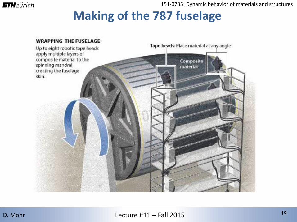
Making of the Boeing 787 fuselage
2/15/2016 19 19Lecture #11 – Fall 2015 19D. Mohr
151-0735: Dynamic behavior of materials and structures
Making of the 787 fuselage
2/15/2016 20 20Lecture #11 – Fall 2015 20D. Mohr
151-0735: Dynamic behavior of materials and structures
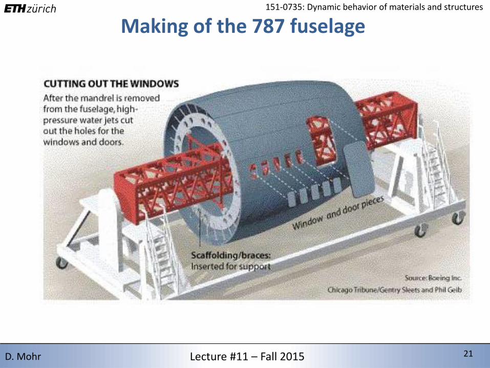
Making of the 787 fuselage
2/15/2016 21 21Lecture #11 – Fall 2015 21D. Mohr
151-0735: Dynamic behavior of materials and structures
Making of the 787 fuselage
2/15/2016 22 22Lecture #11 – Fall 2015 22D. Mohr
151-0735: Dynamic behavior of materials and structures
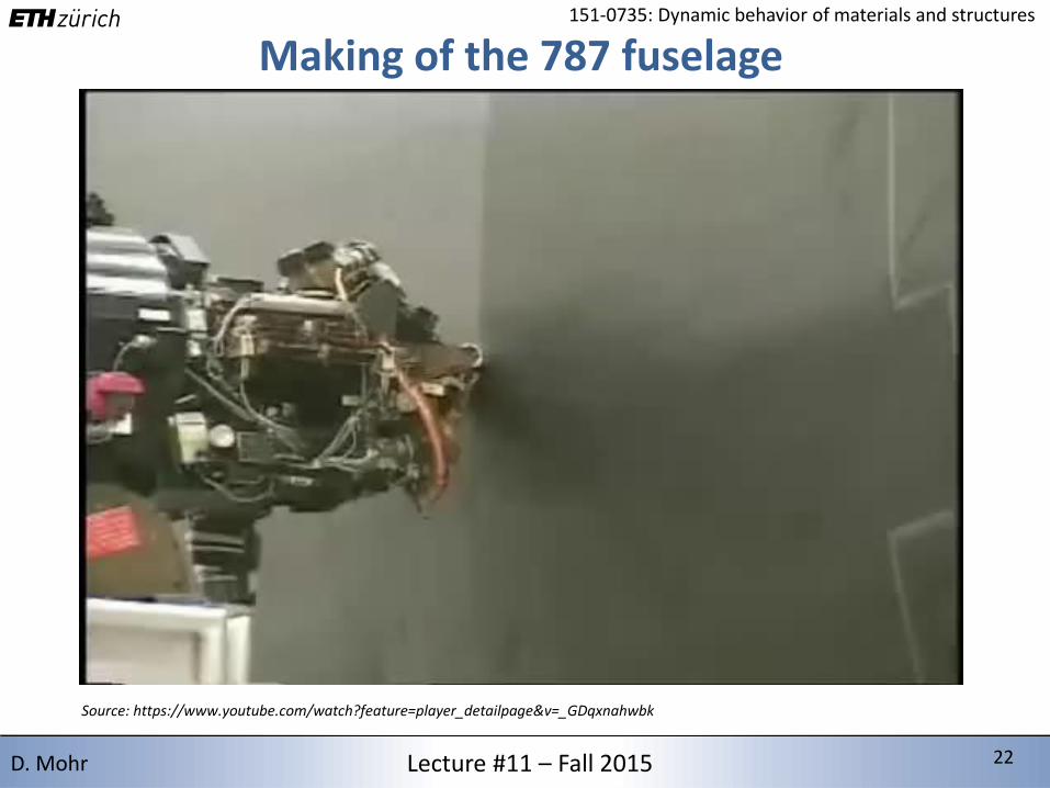
Making of the 787 fuselage
Source: https://www.youtube.com/watch?feature=player_detailpage&v=_GDqxnahwbk
2/15/2016 23 23Lecture #11 – Fall 2015 23D. Mohr
151-0735: Dynamic behavior of materials and structures
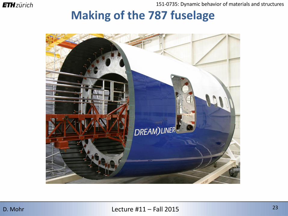
Making of the 787 fuselage
2/15/2016 24 24Lecture #11 – Fall 2015 24D. Mohr
151-0735: Dynamic behavior of materials and structures
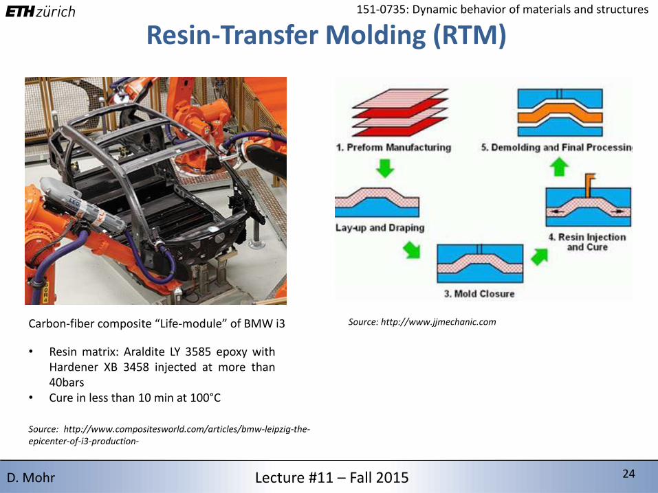
Resin-Transfer Molding (RTM)
Carbon-fiber composite “Life-module” of BMW i3
• Resin matrix: Araldite LY 3585 epoxy withHardener XB 3458 injected at more than40bars
• Cure in less than 10 min at 100°C
Source: http://www.compositesworld.com/articles/bmw-leipzig-the-epicenter-of-i3-production-
Source: http://www.jjmechanic.com
2/15/2016 25 25Lecture #11 – Fall 2015 25D. Mohr
151-0735: Dynamic behavior of materials and structures
Elasticity of Fiber-reinforced Composites
2/15/2016 26 26Lecture #11 – Fall 2015 26D. Mohr
151-0735: Dynamic behavior of materials and structures
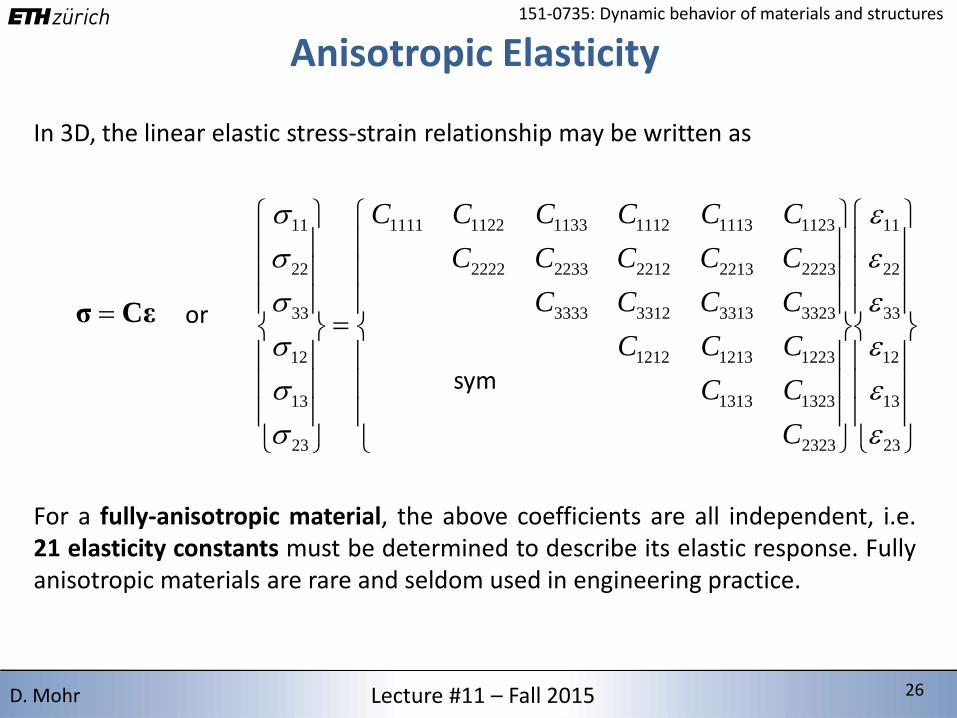
Anisotropic Elasticity
In 3D, the linear elastic stress-strain relationship may be written as
Cεσ or
23
13
12
33
22
11
2323
13231313
122312131212
3323331333123333
22232213221222332222
112311131112113311221111
23
13
12
33
22
11
C
CC
CCC
CCCC
CCCCC
CCCCCC
sym
For a fully-anisotropic material, the above coefficients are all independent, i.e.21 elasticity constants must be determined to describe its elastic response. Fullyanisotropic materials are rare and seldom used in engineering practice.
2/15/2016 27 27Lecture #11 – Fall 2015 27D. Mohr
151-0735: Dynamic behavior of materials and structures
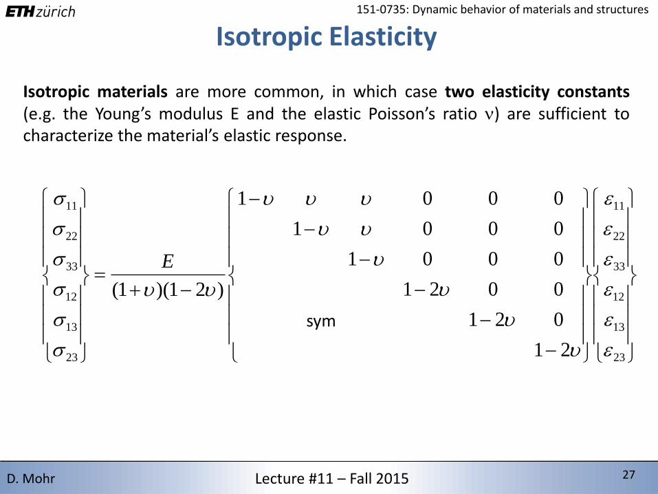
Isotropic Elasticity
Isotropic materials are more common, in which case two elasticity constants(e.g. the Young’s modulus E and the elastic Poisson’s ratio n) are sufficient tocharacterize the material’s elastic response.
23
13
12
33
22
11
23
13
12
33
22
11
21
021
0021
0001
0001
0001
)21)(1(
E
sym
2/15/2016 28 28Lecture #11 – Fall 2015 28D. Mohr
151-0735: Dynamic behavior of materials and structures
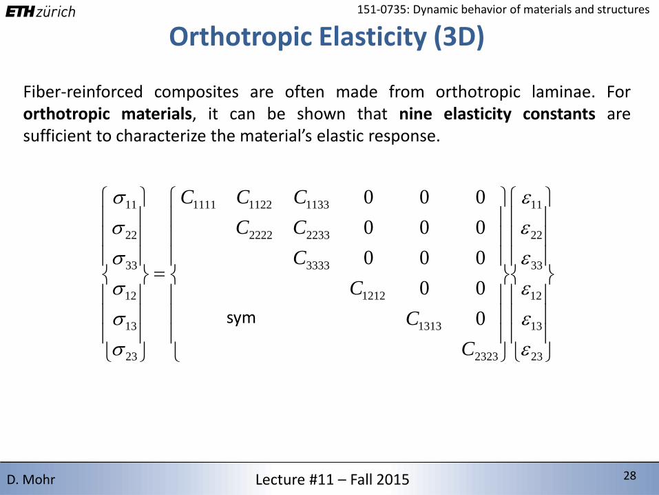
Orthotropic Elasticity (3D)
Fiber-reinforced composites are often made from orthotropic laminae. Fororthotropic materials, it can be shown that nine elasticity constants aresufficient to characterize the material’s elastic response.
sym
23
13
12
33
22
11
2323
1313
1212
3333
22332222
113311221111
23
13
12
33
22
11
0
00
000
000
000
C
C
C
C
CC
CCC
2/15/2016 29 29Lecture #11 – Fall 2015 29D. Mohr
151-0735: Dynamic behavior of materials and structures
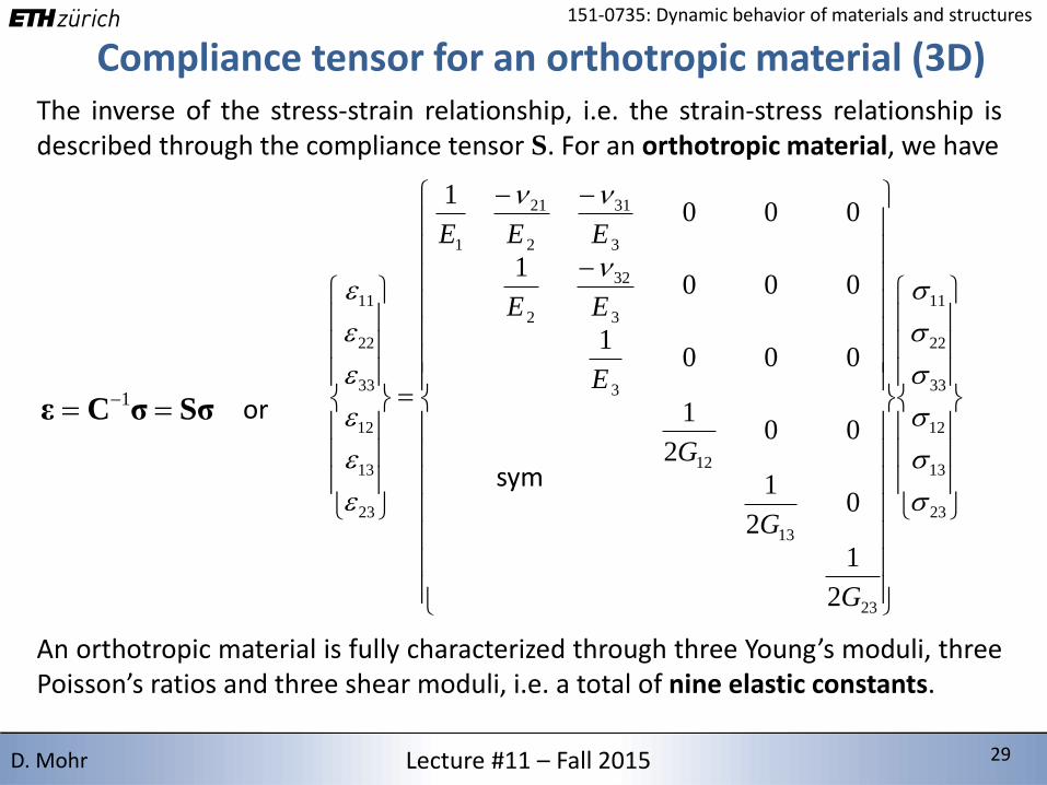
Compliance tensor for an orthotropic material (3D)The inverse of the stress-strain relationship, i.e. the strain-stress relationship isdescribed through the compliance tensor S. For an orthotropic material, we have
SσσCε 1 or
23
13
12
33
22
11
23
13
12
3
3
32
2
3
31
2
21
1
23
13
12
33
22
11
2
1
02
1
002
1
0001
0001
0001
n
nn
G
G
G
E
EE
EEE
sym
An orthotropic material is fully characterized through three Young’s moduli, threePoisson’s ratios and three shear moduli, i.e. a total of nine elastic constants.
2/15/2016 30 30Lecture #11 – Fall 2015 30D. Mohr
151-0735: Dynamic behavior of materials and structures
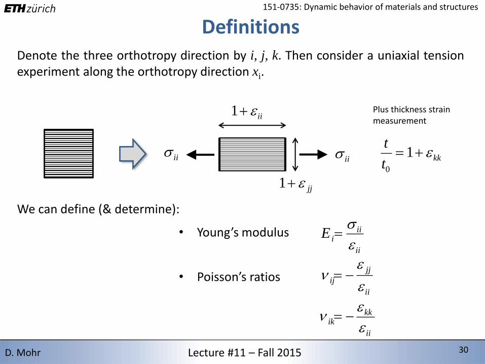
DefinitionsDenote the three orthotropy direction by i, j, k. Then consider a uniaxial tensionexperiment along the orthotropy direction xi.
ii1
jj1
iiii
Plus thickness strain measurement
ii
iiiE
ii
jj
ij
n
kkt
t 1
0
We can define (& determine):
• Young’s modulus
• Poisson’s ratios
ii
kkik
n
2/15/2016 31 31Lecture #11 – Fall 2015 31D. Mohr
151-0735: Dynamic behavior of materials and structures
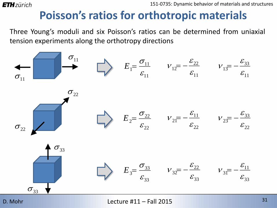
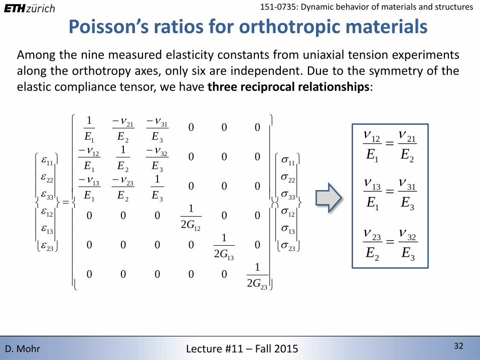
Poisson’s ratios for orthotropic materialsThree Young’s moduli and six Poisson’s ratios can be determined from uniaxialtension experiments along the orthotropy directions
11
11
111
E
11
2212
n
11 11
3313
n
22
22
222
E
22
1121
n
22
3323
n
33
33
333
E
33
2232
n
3333
1131
n
22
2/15/2016 32 32Lecture #11 – Fall 2015 32D. Mohr
151-0735: Dynamic behavior of materials and structures
Poisson’s ratios for orthotropic materialsAmong the nine measured elasticity constants from uniaxial tension experimentsalong the orthotropy axes, only six are independent. Due to the symmetry of theelastic compliance tensor, we have three reciprocal relationships:
23
13
12
33
22
11
23
13
12
32
23
1
13
3
32
21
12
3
31
2
21
1
23
13
12
33
22
11
2
100000
02
10000
002
1000
0001
0001
0001
nn
nn
nn
G
G
G
EEE
EEE
EEE
2
21
1
12
EE
nn
3
31
1
13
EE
nn
3
32
2
23
EE
nn
2/15/2016 33 33Lecture #11 – Fall 2015 33D. Mohr
151-0735: Dynamic behavior of materials and structures
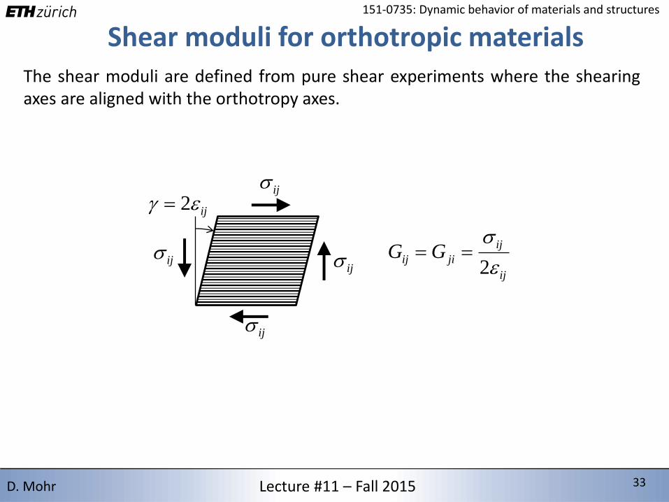
Shear moduli for orthotropic materialsThe shear moduli are defined from pure shear experiments where the shearingaxes are aligned with the orthotropy axes.
ij 2ij
ij
ij
ijij
ij
jiij GG
2
2/15/2016 34 34Lecture #11 – Fall 2015 34D. Mohr
151-0735: Dynamic behavior of materials and structures
Plane stress law for an orthotropic material (2D)
12
22
11
12
2
23
1
13
2
2
21
1
23
13
12
33
22
11
000
000
2
100
0
01
sym
01
G
EE
E
EE
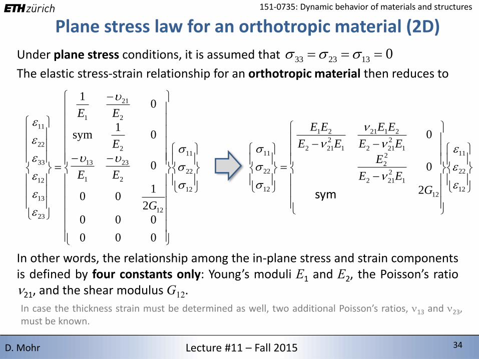
Under plane stress conditions, it is assumed that 0132333
The elastic stress-strain relationship for an orthotropic material then reduces to
In other words, the relationship among the in-plane stress and strain componentsis defined by four constants only: Young’s moduli E1 and E2, the Poisson’s ration21, and the shear modulus G12.
In case the thickness strain must be determined as well, two additional Poisson’s ratios, n13 and n23,must be known.
12
22
11
12
1
2
212
2
2
1
2
212
2121
1
2
212
21
12
22
11
2
0
0
n
n
n
n
G
EE
E
EE
EE
EE
EE
sym
2/15/2016 35 35Lecture #11 – Fall 2015 35D. Mohr
151-0735: Dynamic behavior of materials and structures
Plane stress law for an orthotropic material (2D)
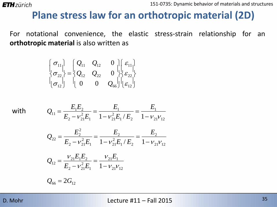
For notational convenience, the elastic stress-strain relationship for anorthotropic material is also written as
1221
2
21
2
21
2
1
2
212
2
222
1/1 nnnn
E
EE
E
EE
EQ
with
12
22
11
66
2212
1211
12
22
11
00
0
0
Q
1221
1
21
2
21
1
1
2
212
2111
1/1 nnnn
E
EE
E
EE
EEQ
1221
121
1
2
212
212112
1 nn
n
n
n
E
EE
EEQ
1266 2GQ
2/15/2016 36 36Lecture #11 – Fall 2015 36D. Mohr
151-0735: Dynamic behavior of materials and structures
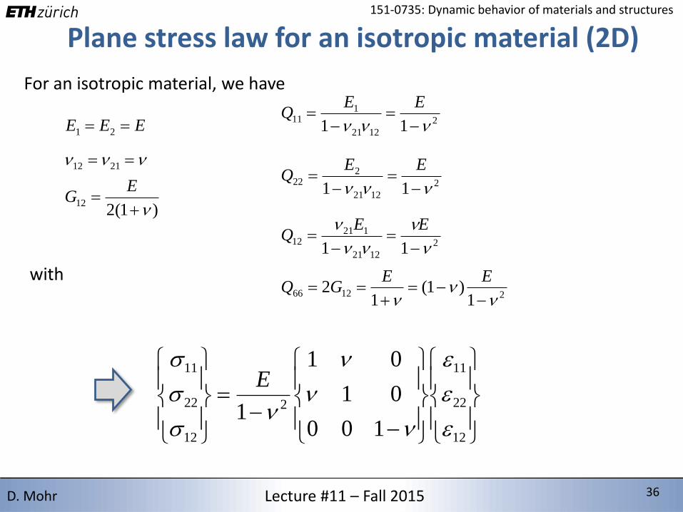
Plane stress law for an isotropic material (2D)
For an isotropic material, we have
2
1221
222
11 nnn
EEQ
with
12
22
11
2
12
22
11
100
01
01
1
n
n
n
n
E
2
1221
111
11 nnn
EEQ
2
1221
12112
11 n
n
nn
n
EEQ
212661
)1(1
2n
nn
EE
GQ
EEE 21
nnn 2112
)1(212
n
EG

2/15/2016 37 37Lecture #11 – Fall 2015 37D. Mohr
151-0735: Dynamic behavior of materials and structures
Isotropy check
2221 n
E
Q
2111 n
E
Q
2121 n
n
EQ
2661
)1(n
n
E
Q
1122 QQ
11
12
Q
Qn
121111
11
1266 1 QQQ
Q
66
2212
1211
00
0
0
Q
Q1122 QQ
121166 QQQ defines an isotropic material if
2/15/2016 38 38Lecture #11 – Fall 2015 38D. Mohr
151-0735: Dynamic behavior of materials and structures
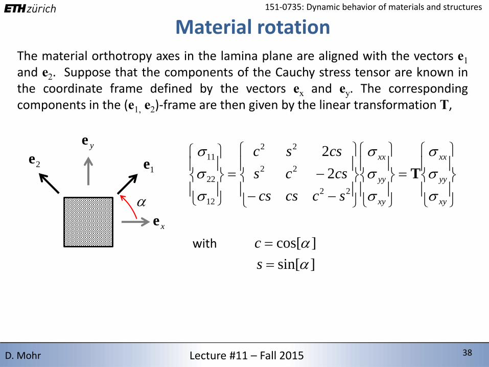
Material rotation
1e2e
xe
ye
The material orthotropy axes in the lamina plane are aligned with the vectors e1and e2. Suppose that the components of the Cauchy stress tensor are known inthe coordinate frame defined by the vectors ex and ey. The correspondingcomponents in the (e1, e2)-frame are then given by the linear transformation T,
xy
yy
xx
xy
yy
xx
sccscs
cscs
cssc
T22
22
22
12
22
11
2
2
with ]cos[c
]sin[s
2/15/2016 39 39Lecture #11 – Fall 2015 39D. Mohr
151-0735: Dynamic behavior of materials and structures
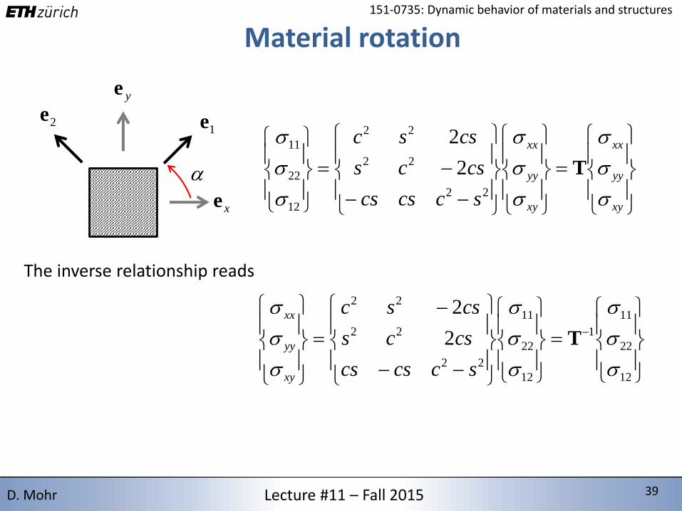
Material rotation
1e2e
xe
ye
The inverse relationship reads
xy
yy
xx
xy
yy
xx
sccscs
cscs
cssc
T22
22
22
12
22
11
2
2
12
22
11
1
12
22
11
22
22
22
2
2
T
sccscs
cscs
cssc
xy
yy
xx

2/15/2016 40 40Lecture #11 – Fall 2015 40D. Mohr
151-0735: Dynamic behavior of materials and structures
Constitutive equation for lamina As the same transformations are valid for the strain vector, the relationshipamong the stress and strain components in the (ex, ey)-frame is then given by
xy
yy
xx
xy
yy
xx
xy
yy
xx
Q
QQQ
Q
66
2622
161211
66
2212
1211
1
ˆ
ˆˆ
ˆˆˆ
00
0
0
TT
22
4
6612
22
11
4
11 )(2ˆ QsQQscQcQ
Upon evaluation, we find the components
12
44
662211
22
12 )()2(ˆ QcsQQQscQ
)(2)(2ˆ662212
3
661211
3
16 QQQcsQQQscQ
22
4
6612
22
11
4
22 )(2ˆ QcQQscQsQ
)(2)(2ˆ662212
3
661211
3
26 QQQscQQQcsQ
66
44
66122211
22
66 )()2(2ˆ QscQQQQscQ
Note that the mathematical definition of the shear strain is applied. Many textbooks and FE programs adopt theengineering definition. In that case, the third column of the stiffness matrix Q needs to be multiplied with 0.5.
sym
2/15/2016 41 41Lecture #11 – Fall 2015 41D. Mohr
151-0735: Dynamic behavior of materials and structures
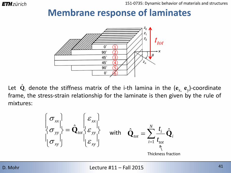
Membrane response of laminates
Let denote the stiffness matrix of the i-th lamina in the (ex, ey)-coordinateframe, the stress-strain relationship for the laminate is then given by the rule ofmixtures:
xy
yy
xx
tot
xy
yy
xx
Q̂
iQ̂
with
N
i
i
tot
itot
t
t
1
ˆˆ QQ
ttot①②③④⑤⑥
Thickness fraction
2/15/2016 42 42Lecture #11 – Fall 2015 42D. Mohr
151-0735: Dynamic behavior of materials and structures
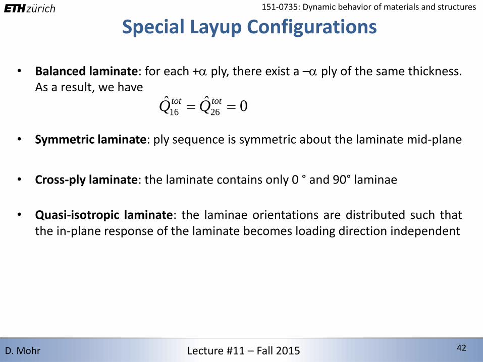
Special Layup Configurations
• Balanced laminate: for each + ply, there exist a – ply of the same thickness.As a result, we have
0ˆˆ2616 tottot QQ
• Symmetric laminate: ply sequence is symmetric about the laminate mid-plane
• Cross-ply laminate: the laminate contains only 0 ° and 90° laminae
• Quasi-isotropic laminate: the laminae orientations are distributed such thatthe in-plane response of the laminate becomes loading direction independent
2/15/2016 43 43Lecture #11 – Fall 2015 43D. Mohr
151-0735: Dynamic behavior of materials and structures
Reading Materials for Lecture #11• E.J. Barbero (2011), Introduction to Composite Materials Design
• R. Talreja, C. Veer Singh (2012), Damage and Failure of Composite Materials


![92 / 0735-54-2510 · 2020. 3. 11. · 13 El (El) (8:30 (JYfiÎfiffiìËùíj 2,800 1,800 IT] 830 0735-54-2510 0735-54-1540 info ev@ugui-vc.jp (tBñ)](https://static.fdocuments.in/doc/165x107/60c46723ecb8834234005d27/92-0735-54-2510-2020-3-11-13-el-el-830-jyfififfij-2800-1800.jpg)