Lecture -11 Analysis and Design of Two-Way Slab Systems (Two-Way Slab With Beams & Two Way Joist...
64
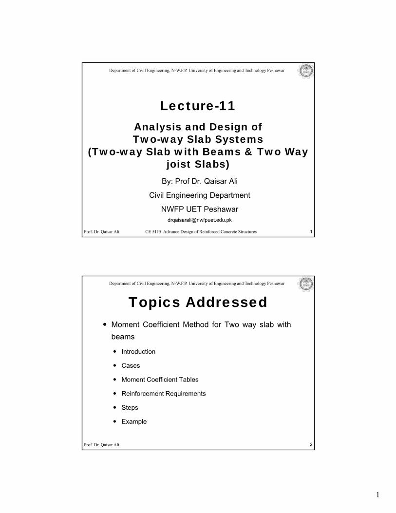
1 Department of Civil Engineering, N-W.F.P. University of Engineering and Technology Peshawar Lecture-11 Analysis and Design of Two-way Slab Systems (Two-way Slab with Beams & Two Way joist Slabs) B P fD Qi Ali Prof. Dr. Qaisar Ali CE 5115 Advance Design of Reinforced Concrete Structures 1 By: Prof Dr. Qaisar Ali Civil Engineering Department NWFP UET Peshawar [email protected] Department of Civil Engineering, N-W.F.P. University of Engineering and Technology Peshawar Topics Addressed Moment Coefficient Method for Two way slab with b beams Introduction Cases Moment Coefficient Tables Rif t R i t Prof. Dr. Qaisar Ali Reinforcement Requirements Steps Example 2
-
Upload
ragah-sammi -
Category
Documents
-
view
410 -
download
74
Transcript of Lecture -11 Analysis and Design of Two-Way Slab Systems (Two-Way Slab With Beams & Two Way Joist...
1
Department of Civil Engineering, N-W.F.P. University of Engineering and Technology Peshawar
Lecture-11Analysis and Design of Two-way Slab Systems
(Two-way Slab with Beams & Two Way joist Slabs)
B P f D Q i Ali
Prof. Dr. Qaisar Ali CE 5115 Advance Design of Reinforced Concrete Structures 1
By: Prof Dr. Qaisar Ali
Civil Engineering Department
NWFP UET [email protected]
Department of Civil Engineering, N-W.F.P. University of Engineering and Technology Peshawar
Topics AddressedMoment Coefficient Method for Two way slab withbbeams
Introduction
Cases
Moment Coefficient Tables
R i f t R i t
Prof. Dr. Qaisar Ali
Reinforcement Requirements
Steps
Example
2
2
Department of Civil Engineering, N-W.F.P. University of Engineering and Technology Peshawar
Topics AddressedTwo-way Joist Slab
Introduction
Behavior
Characteristics
Basic Steps for Structural Design
Prof. Dr. Qaisar Ali
Example
3
Department of Civil Engineering, N-W.F.P. University of Engineering and Technology Peshawar
Moment Coefficient Method (Introduction)
Two Way Slabs
The Moment Coefficient Method included for the first time in1963 ACI Code is applicable to two-way slabs supported onfour sides of each slab panel by walls, steel beams relativelydeep, stiff, edge beams (h = 3hf).
Although, not included in 1977 and later versions of ACI code,
Prof. Dr. Qaisar Ali
its continued use is permissible under the ACI 318-08 codeprovision (13.5.1). Visit ACI 13.5.1.
4
3
Department of Civil Engineering, N-W.F.P. University of Engineering and Technology Peshawar
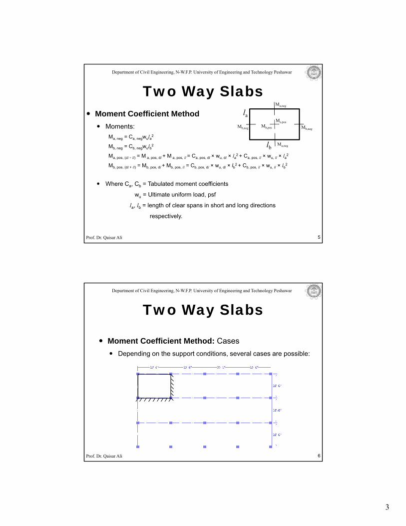
Moment Coefficient Method la
Ma,neg
Ma,pos
Two Way Slabs
Moments:Ma, neg = Ca, negwula2
Mb, neg = Cb, negwulb2
Ma, pos, (dl + ll) = M a, pos, dl + M a, pos, ll = Ca, pos, dl × wu, dl × la2 + Ca, pos, ll × wu, ll × la2
Mb, pos, (dl + ll) = Mb, pos, dl + Mb, pos, ll = Cb, pos, dl × wu, dl × lb2 + Cb, pos, ll × wu, ll × lb2
Where C C = Tabulated moment coefficients
Ma,neglb
Mb,neg Mb,negMb,pos
Prof. Dr. Qaisar Ali
Where Ca, Cb = Tabulated moment coefficients
wu = Ultimate uniform load, psf
la, lb = length of clear spans in short and long directions
respectively.
5
Department of Civil Engineering, N-W.F.P. University of Engineering and Technology Peshawar
Moment Coefficient Method: Cases
Two Way Slabs
Moment Coefficient Method: CasesDepending on the support conditions, several cases are possible:
Prof. Dr. Qaisar Ali 6
4
Department of Civil Engineering, N-W.F.P. University of Engineering and Technology Peshawar
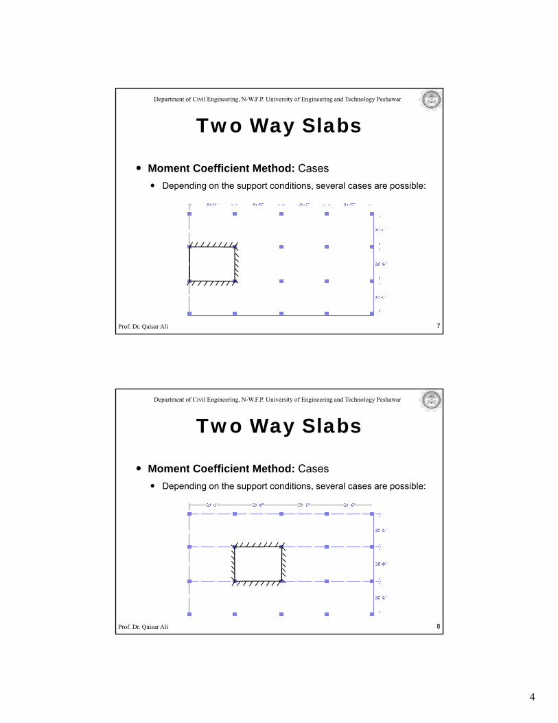
Moment Coefficient Method: Cases
Two Way Slabs
Moment Coefficient Method: CasesDepending on the support conditions, several cases are possible:
Prof. Dr. Qaisar Ali 7
Department of Civil Engineering, N-W.F.P. University of Engineering and Technology Peshawar
Moment Coefficient Method: Cases
Two Way Slabs
Moment Coefficient Method: CasesDepending on the support conditions, several cases are possible:
Prof. Dr. Qaisar Ali 8
5
Department of Civil Engineering, N-W.F.P. University of Engineering and Technology Peshawar
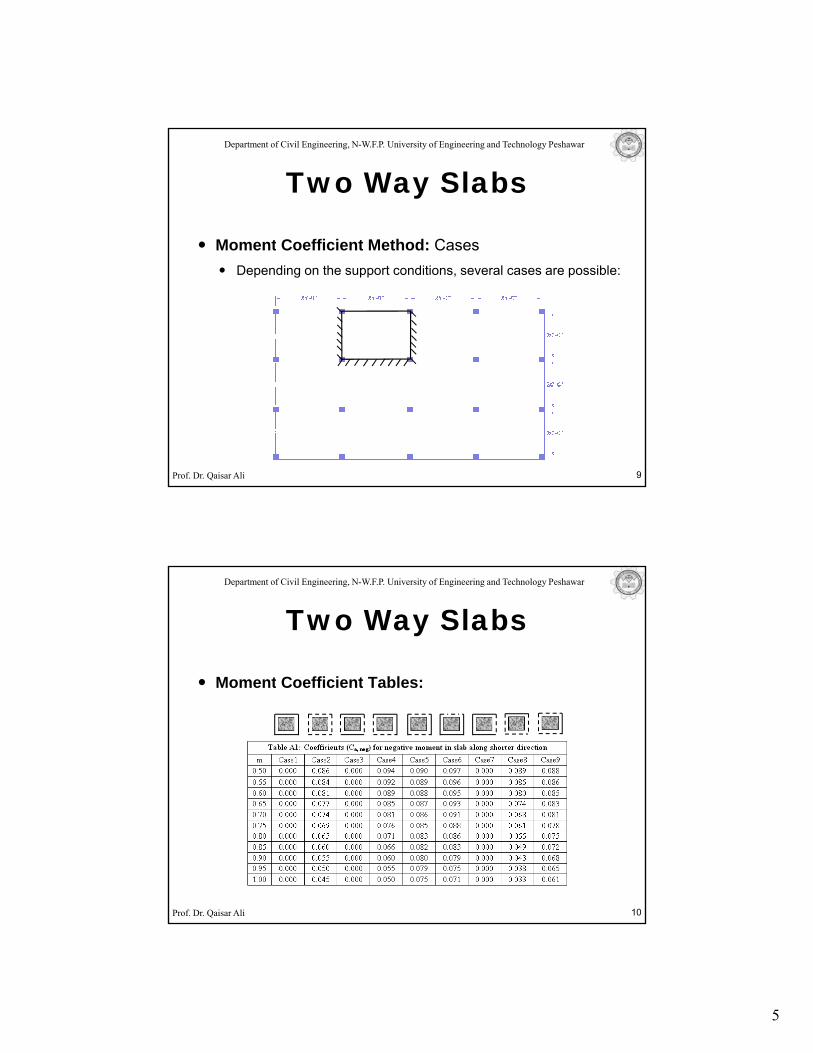
Moment Coefficient Method: Cases
Two Way Slabs
Moment Coefficient Method: CasesDepending on the support conditions, several cases are possible:
Prof. Dr. Qaisar Ali 9
Department of Civil Engineering, N-W.F.P. University of Engineering and Technology Peshawar
Two Way Slabs
Moment Coefficient Tables:Moment Coefficient Tables:
Prof. Dr. Qaisar Ali 10
6
Department of Civil Engineering, N-W.F.P. University of Engineering and Technology Peshawar
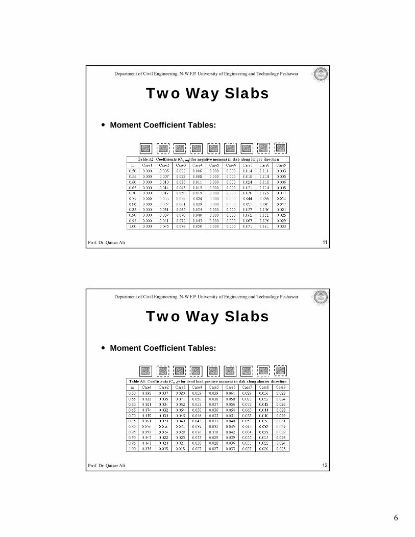
Two Way Slabs
Moment Coefficient Tables:Moment Coefficient Tables:
Prof. Dr. Qaisar Ali 11
Department of Civil Engineering, N-W.F.P. University of Engineering and Technology Peshawar
Two Way Slabs
Moment Coefficient Tables:Moment Coefficient Tables:
Prof. Dr. Qaisar Ali 12
7
Department of Civil Engineering, N-W.F.P. University of Engineering and Technology Peshawar
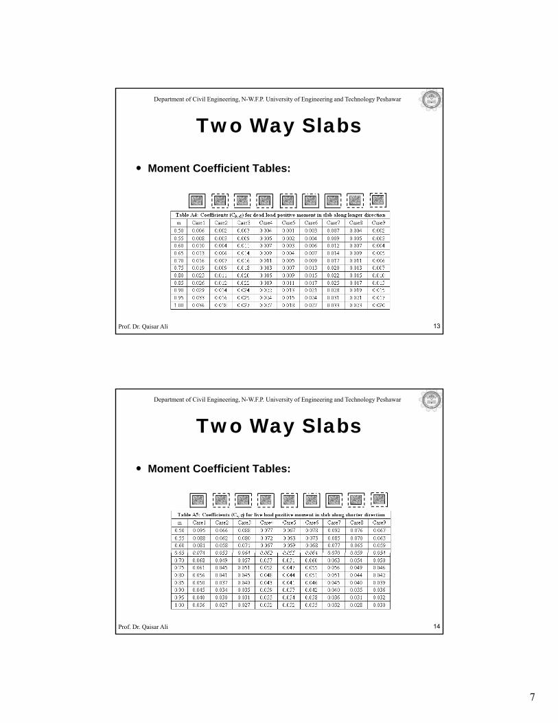
Two Way Slabs
Moment Coefficient Tables:Moment Coefficient Tables:
Prof. Dr. Qaisar Ali 13
Department of Civil Engineering, N-W.F.P. University of Engineering and Technology Peshawar
Two Way Slabs
Moment Coefficient Tables:Moment Coefficient Tables:
Prof. Dr. Qaisar Ali 14
8
Department of Civil Engineering, N-W.F.P. University of Engineering and Technology Peshawar
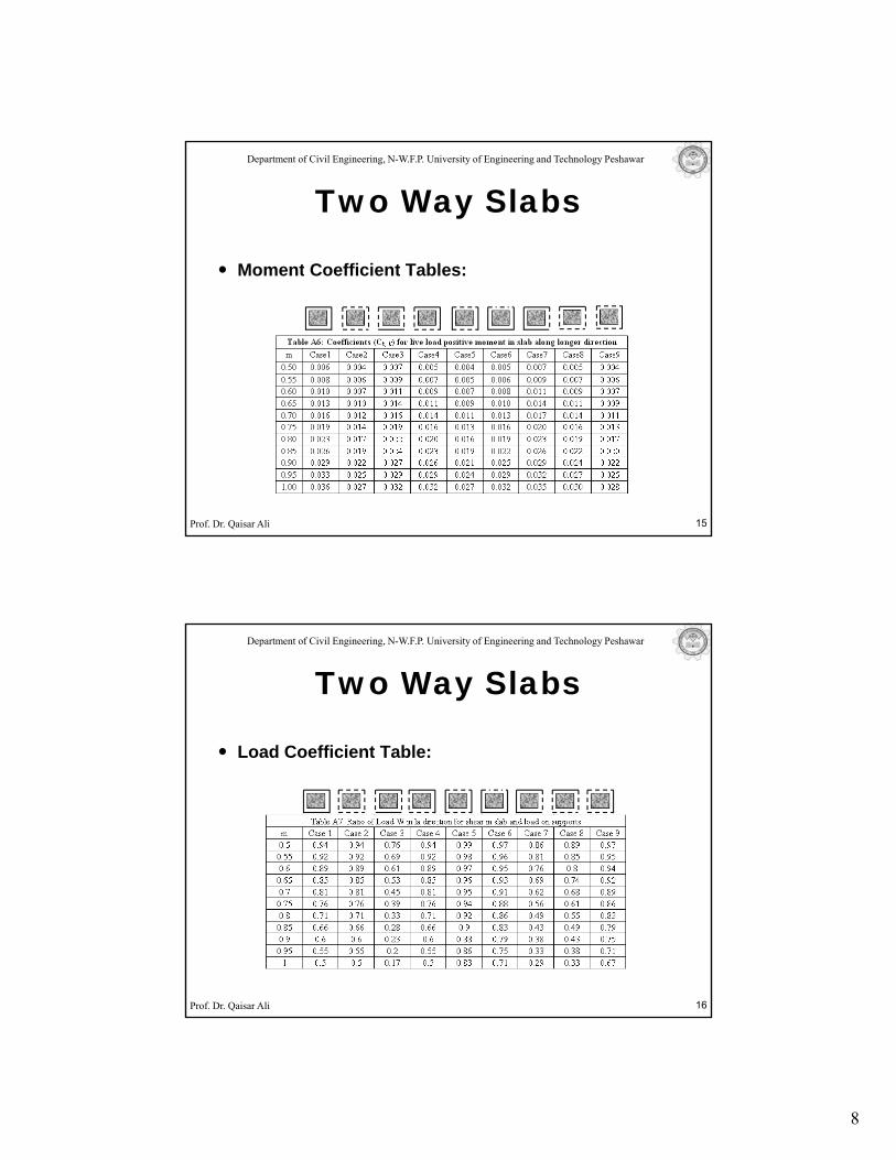
Two Way Slabs
Moment Coefficient Tables:Moment Coefficient Tables:
Prof. Dr. Qaisar Ali 15
Department of Civil Engineering, N-W.F.P. University of Engineering and Technology Peshawar
Two Way Slabs
Load Coefficient Table:Load Coefficient Table:
Prof. Dr. Qaisar Ali 16
9
Department of Civil Engineering, N-W.F.P. University of Engineering and Technology Peshawar
Maximum spacing and minimum reinforcement
Two Way Slabs
requirement:
Maximum spacing (ACI 13.3.2):
smax = 2 hf in each direction.
Minimum Reinforcement (ACI 7.12.2.1):
Asmin = 0.0018 b hf for grade 60.
Prof. Dr. Qaisar Ali 17
Asmin 0.0018 b hf for grade 60.
Asmin = 0.002 b hf for grade 40 and 50.
Department of Civil Engineering, N-W.F.P. University of Engineering and Technology Peshawar
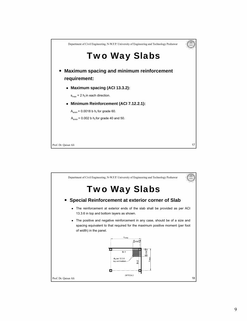
Special Reinforcement at exterior corner of SlabThe reinforcement at exterior ends of the slab shall be provided as per ACI
Two Way Slabs
The reinforcement at exterior ends of the slab shall be provided as per ACI13.3.6 in top and bottom layers as shown.
The positive and negative reinforcement in any case, should be of a size andspacing equivalent to that required for the maximum positive moment (per footof width) in the panel.
Prof. Dr. Qaisar Ali 18
10
Department of Civil Engineering, N-W.F.P. University of Engineering and Technology Peshawar
Moment Coefficient Method
Two Way Slabs
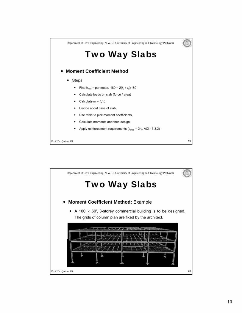
Steps
Find hmin = perimeter/ 180 = 2(la + lb)/180
Calculate loads on slab (force / area)
Calculate m = la/ lb
Decide about case of slab,
Prof. Dr. Qaisar Ali
Decide about case of slab,
Use table to pick moment coefficients,
Calculate moments and then design.
Apply reinforcement requirements (smax = 2hf, ACI 13.3.2)
19
Department of Civil Engineering, N-W.F.P. University of Engineering and Technology Peshawar
Moment Coefficient Method: Example
Two Way Slabs
o e t Coe c e t et od a p e
A 100′ × 60′, 3-storey commercial building is to be designed.The grids of column plan are fixed by the architect.
Prof. Dr. Qaisar Ali 20
11
Department of Civil Engineering, N-W.F.P. University of Engineering and Technology Peshawar
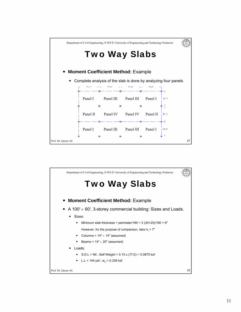
Moment Coefficient Method: Example
Two Way Slabs
o e t Coe c e t et od a p e
Complete analysis of the slab is done by analyzing four panels
Panel I Panel IPanel III Panel III
Prof. Dr. Qaisar Ali 21
Panel I Panel I
Panel II Panel II
Panel III Panel III
Panel IV Panel IV
Department of Civil Engineering, N-W.F.P. University of Engineering and Technology Peshawar
Moment Coefficient Method: Example
Two Way Slabs
p
A 100′ × 60′, 3-storey commercial building: Sizes and Loads.Sizes:
Minimum slab thickness = perimeter/180 = 2 (20+25)/180 = 6″
However, for the purpose of comparison, take hf = 7″
Columns = 14″ × 14″ (assumed)
Prof. Dr. Qaisar Ali
Beams = 14″ × 20″ (assumed)
Loads:
S.D.L = Nil ; Self Weight = 0.15 x (7/12) = 0.0875 ksf
L.L = 144 psf ; wu = 0.336 ksf
22
12
Department of Civil Engineering, N-W.F.P. University of Engineering and Technology Peshawar
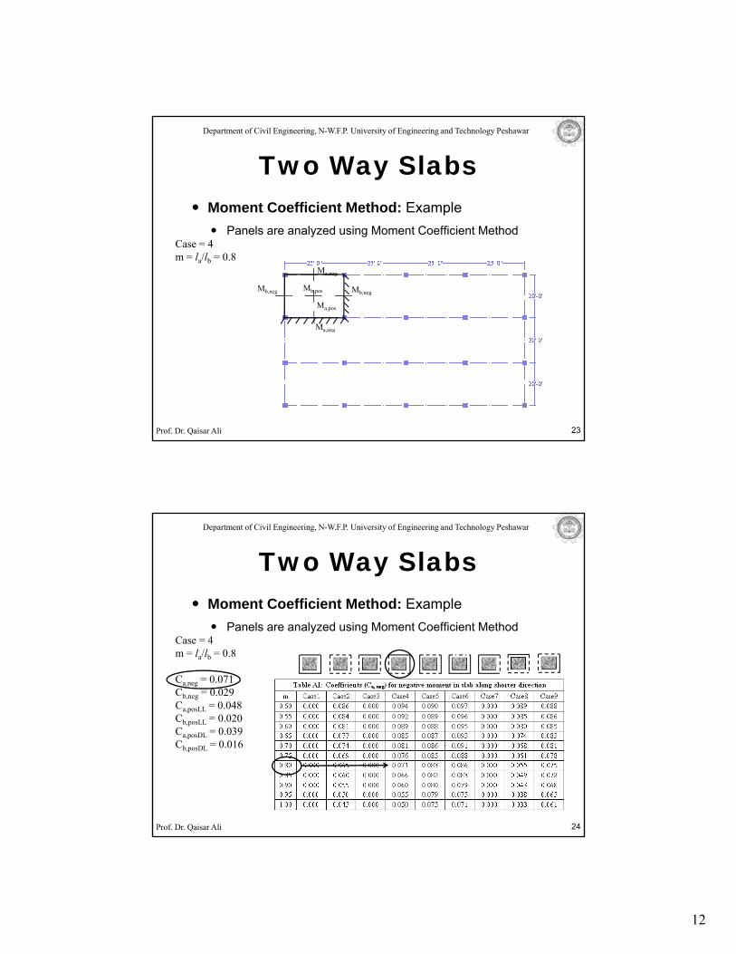
Moment Coefficient Method: Example
Two Way Slabs
Panels are analyzed using Moment Coefficient MethodCase = 4m = la/lb = 0.8
Mb,neg Mb,negMb,pos
Ma,neg
Ma,pos
Ma,neg
Prof. Dr. Qaisar Ali 23
Department of Civil Engineering, N-W.F.P. University of Engineering and Technology Peshawar
Moment Coefficient Method: Example
Two Way Slabs
Panels are analyzed using Moment Coefficient MethodCase = 4m = la/lb = 0.8
Ca,neg = 0.071Cb,neg = 0.029Ca,posLL = 0.048Cb,posLL = 0.020C 0 039
Prof. Dr. Qaisar Ali 24
Ca,posDL = 0.039Cb,posDL = 0.016
13
Department of Civil Engineering, N-W.F.P. University of Engineering and Technology Peshawar
Moment Coefficient Method: Example
Two Way Slabs
Panels are analyzed using Moment Coefficient MethodCase = 4m = la/lb = 0.8
Ca,neg = 0.071Cb,neg = 0.029Ca,posLL = 0.048Cb,posLL = 0.020C 0 039
Prof. Dr. Qaisar Ali 25
Ca,posDL = 0.039Cb,posDL = 0.016
Department of Civil Engineering, N-W.F.P. University of Engineering and Technology Peshawar
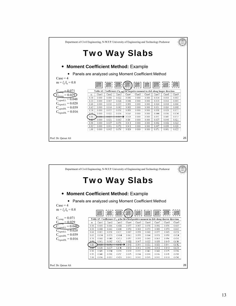
Moment Coefficient Method: Example
Two Way Slabs
Panels are analyzed using Moment Coefficient MethodCase = 4m = la/lb = 0.8
Ca,neg = 0.071Cb,neg = 0.029Ca,posLL = 0.048Cb,posLL = 0.020C 0 039
Prof. Dr. Qaisar Ali 26
Ca,posDL = 0.039Cb,posDL = 0.016
14
Department of Civil Engineering, N-W.F.P. University of Engineering and Technology Peshawar
Moment Coefficient Method: Example
Two Way Slabs
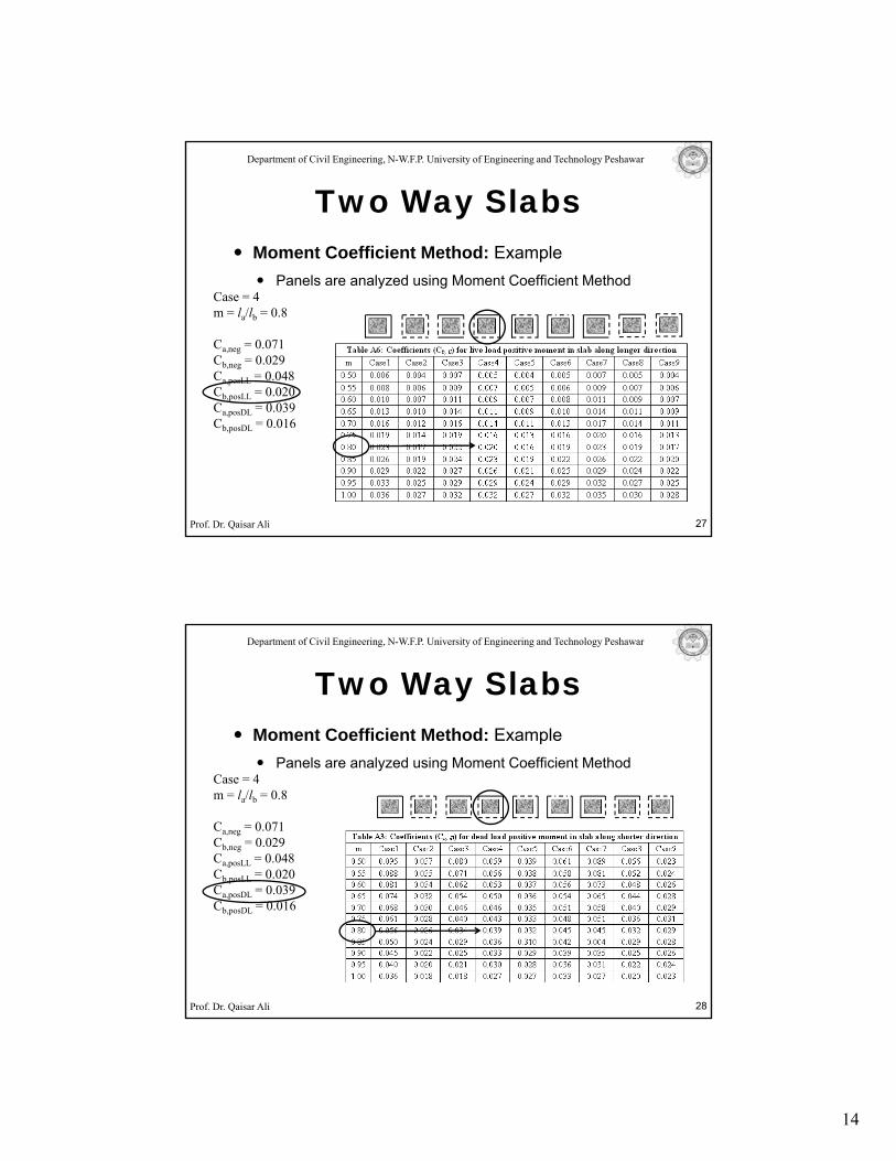
Panels are analyzed using Moment Coefficient MethodCase = 4m = la/lb = 0.8
Ca,neg = 0.071Cb,neg = 0.029Ca,posLL = 0.048Cb,posLL = 0.020C 0 039
Prof. Dr. Qaisar Ali 27
Ca,posDL = 0.039Cb,posDL = 0.016
Department of Civil Engineering, N-W.F.P. University of Engineering and Technology Peshawar
Moment Coefficient Method: Example
Two Way Slabs
Panels are analyzed using Moment Coefficient MethodCase = 4m = la/lb = 0.8
Ca,neg = 0.071Cb,neg = 0.029Ca,posLL = 0.048Cb,posLL = 0.020C 0 039
Prof. Dr. Qaisar Ali 28
Ca,posDL = 0.039Cb,posDL = 0.016
15
Department of Civil Engineering, N-W.F.P. University of Engineering and Technology Peshawar
Moment Coefficient Method: Example
Two Way Slabs
Panels are analyzed using Moment Coefficient MethodCase = 4m = la/lb = 0.8
Ca,neg = 0.071Cb,neg = 0.029Ca,posLL = 0.048Cb,posLL = 0.020C 0 039
Prof. Dr. Qaisar Ali 29
Ca,posDL = 0.039Cb,posDL = 0.016
Department of Civil Engineering, N-W.F.P. University of Engineering and Technology Peshawar
Moment Coefficient Method: Example
Two Way Slabs
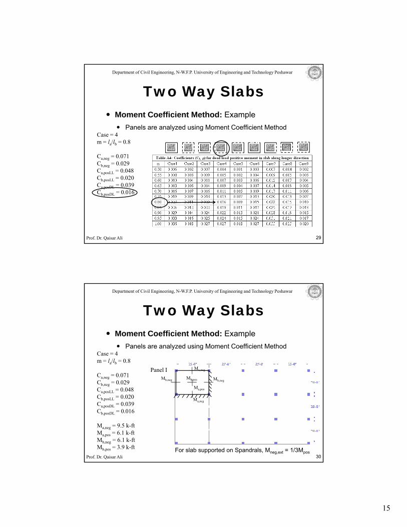
Panels are analyzed using Moment Coefficient Method
Panel I
Case = 4m = la/lb = 0.8
Ca,neg = 0.071Cb,neg = 0.029Ca,posLL = 0.048Cb,posLL = 0.020C 0 039
Mb,neg Mb,negMb,pos
Ma,neg
Ma,pos
Ma,neg
Prof. Dr. Qaisar Ali 30
Ca,posDL = 0.039Cb,posDL = 0.016
Ma,neg = 9.5 k-ftMa,pos = 6.1 k-ftMb,neg = 6.1 k-ftMb,pos = 3.9 k-ft For slab supported on Spandrals, Mneg,ext = 1/3Mpos
16
Department of Civil Engineering, N-W.F.P. University of Engineering and Technology Peshawar
Two Way SlabsMoment Coefficient Method: Example
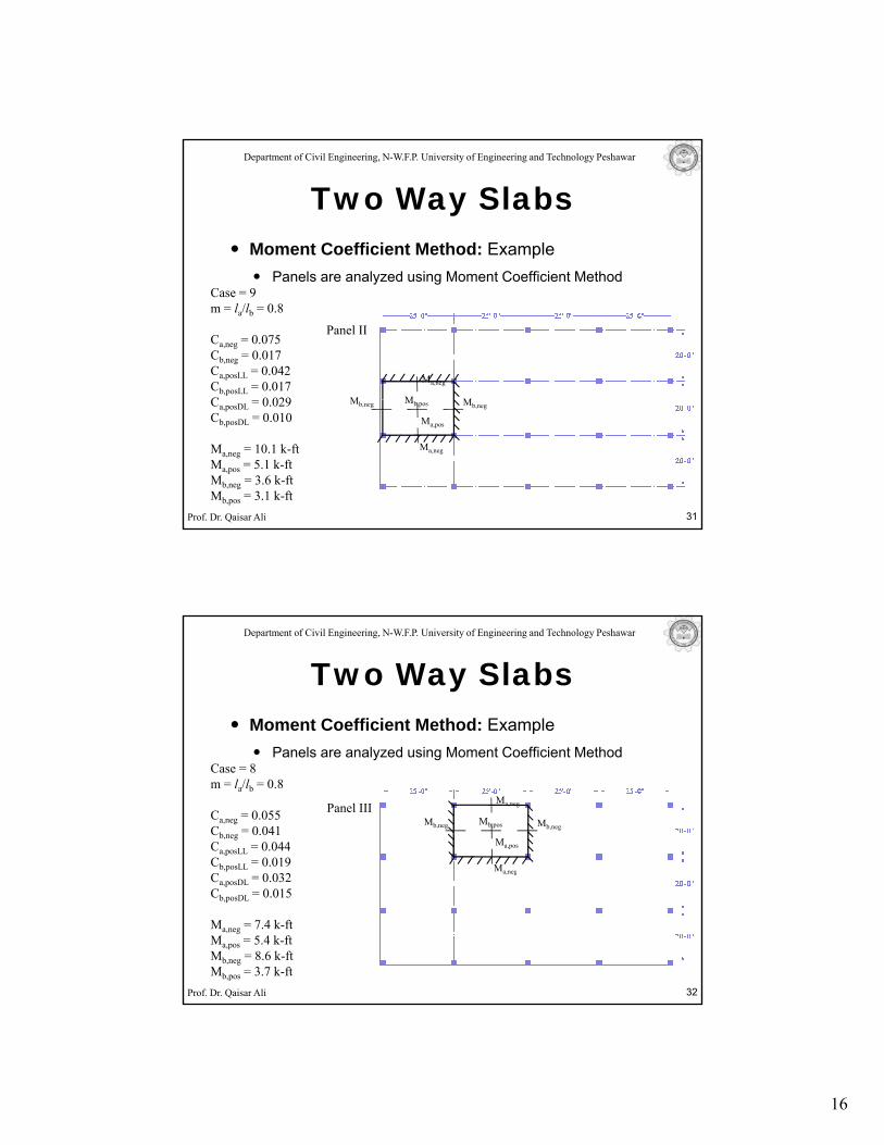
Panel II
Case = 9m = la/lb = 0.8
Ca,neg = 0.075Cb,neg = 0.017Ca,posLL = 0.042Cb,posLL = 0.017C 0 029 M MM
Ma,neg
Panels are analyzed using Moment Coefficient Method
Prof. Dr. Qaisar Ali 31
Ca,posDL = 0.029Cb,posDL = 0.010
Ma,neg = 10.1 k-ftMa,pos = 5.1 k-ftMb,neg = 3.6 k-ftMb,pos = 3.1 k-ft
Mb,neg Mb,negMb,pos
Ma,pos
Ma,neg
Department of Civil Engineering, N-W.F.P. University of Engineering and Technology Peshawar
Two Way SlabsMoment Coefficient Method: Example
Panel III
Case = 8m = la/lb = 0.8
Ca,neg = 0.055Cb,neg = 0.041Ca,posLL = 0.044Cb,posLL = 0.019C 0 032
Mb,neg Mb,negMb,pos
Ma,neg
Ma,pos
Ma,neg
Panels are analyzed using Moment Coefficient Method
Prof. Dr. Qaisar Ali 32
Ca,posDL = 0.032Cb,posDL = 0.015
Ma,neg = 7.4 k-ftMa,pos = 5.4 k-ftMb,neg = 8.6 k-ftMb,pos = 3.7 k-ft
17
Department of Civil Engineering, N-W.F.P. University of Engineering and Technology Peshawar
Two Way SlabsMoment Coefficient Method: Example
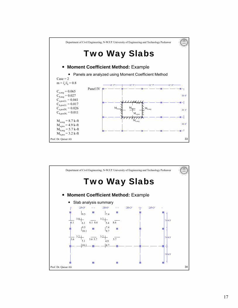
Panel IV
Case = 2m = la/lb = 0.8
Ca,neg = 0.065Cb,neg = 0.027Ca,posLL = 0.041Cb,posLL = 0.017C 0 026 M MM
Ma,neg
Panels are analyzed using Moment Coefficient Method
Prof. Dr. Qaisar Ali 33
Ca,posDL = 0.026Cb,posDL = 0.011
Ma,neg = 8.7 k-ftMa,pos = 4.9 k-ftMb,neg = 5.7 k-ftMb,pos = 3.2 k-ft
Mb,neg Mb,negMb,pos
Ma,pos
Ma,neg
Department of Civil Engineering, N-W.F.P. University of Engineering and Technology Peshawar
Two Way SlabsMoment Coefficient Method: Example
Slab analysis summary
8.77.4
7.4
8.6 8.65.43.7
10.19.5
9.5
6.1 6.13.9
6.1
Prof. Dr. Qaisar Ali 34
3.2
4.95.75.7
8.7
3.25.13.6
10.1
3.6
18
Department of Civil Engineering, N-W.F.P. University of Engineering and Technology Peshawar
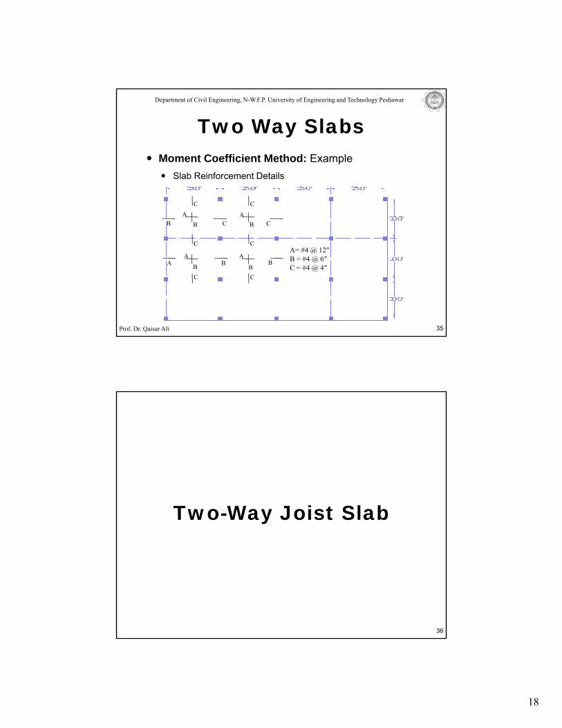
Two Way SlabsMoment Coefficient Method: Example
Slab Reinforcement Details
A
C
C
C CBA
A
C
C
B BA
A= #4 @ 12″
Prof. Dr. Qaisar Ali 35
A
BBB
C
A
BA
C
@B = #4 @ 6″C = #4 @ 4″
Two-Way Joist Slab
36
19
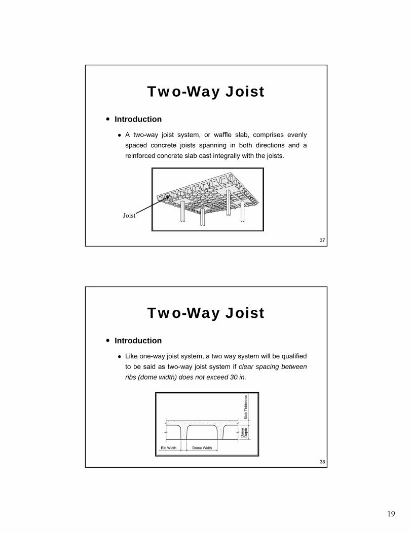
Introduction
Two-Way Joist
A two-way joist system, or waffle slab, comprises evenlyspaced concrete joists spanning in both directions and areinforced concrete slab cast integrally with the joists.
37
Joist
Introduction
Two-Way Joist
Like one-way joist system, a two way system will be qualifiedto be said as two-way joist system if clear spacing betweenribs (dome width) does not exceed 30 in.
38
20
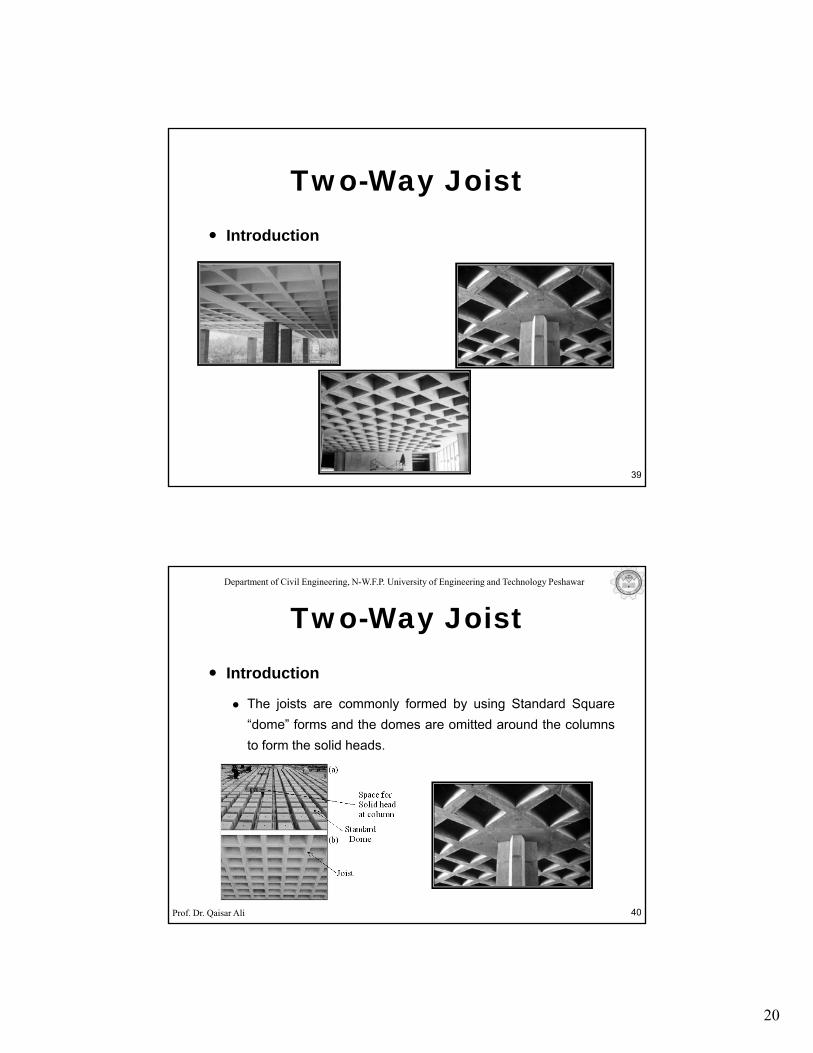
Introduction
Two-Way Joist
39
Department of Civil Engineering, N-W.F.P. University of Engineering and Technology Peshawar
Introduction
Two-Way Joist
The joists are commonly formed by using Standard Square“dome” forms and the domes are omitted around the columnsto form the solid heads.
Prof. Dr. Qaisar Ali 40
21
Department of Civil Engineering, N-W.F.P. University of Engineering and Technology Peshawar
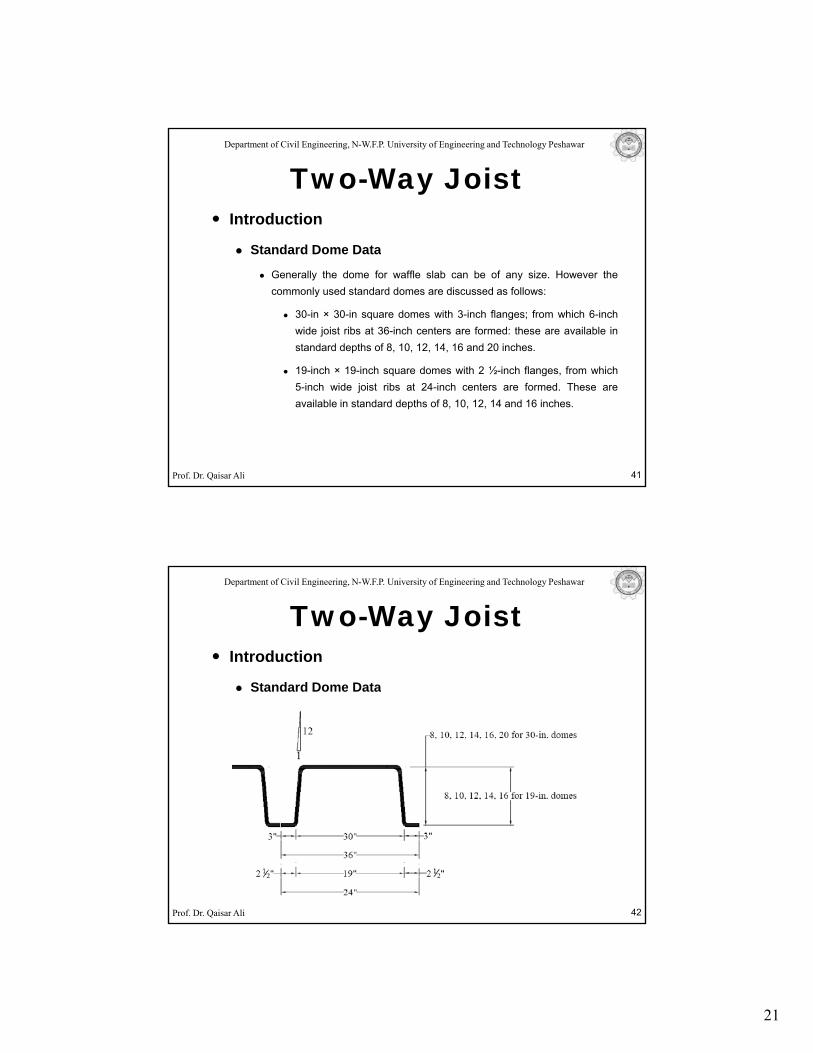
Introduction
Standard Dome Data
Two-Way Joist
Standard Dome Data
Generally the dome for waffle slab can be of any size. However thecommonly used standard domes are discussed as follows:
30-in × 30-in square domes with 3-inch flanges; from which 6-inchwide joist ribs at 36-inch centers are formed: these are available instandard depths of 8, 10, 12, 14, 16 and 20 inches.
19 i h 19 i h d ith 2 ½ i h fl f hi h
Prof. Dr. Qaisar Ali
19-inch × 19-inch square domes with 2 ½-inch flanges, from which5-inch wide joist ribs at 24-inch centers are formed. These areavailable in standard depths of 8, 10, 12, 14 and 16 inches.
41
Department of Civil Engineering, N-W.F.P. University of Engineering and Technology Peshawar
Introduction
Standard Dome Data
Two-Way Joist
Standard Dome Data
Prof. Dr. Qaisar Ali 42
22
Department of Civil Engineering, N-W.F.P. University of Engineering and Technology Peshawar
Behavior
Two-Way Joist
The behavior of two-way joist slab is similar to a two way flatSlab system.
Prof. Dr. Qaisar Ali
Department of Civil Engineering, N-W.F.P. University of Engineering and Technology Peshawar
Characteristics
Two-Way Joist
Dome voids reduce dead load
Attractive ceiling (waffle like appearance)
Electrical fixtures can be placed in the voids
Particularly advantageous where the use of longer spans
Prof. Dr. Qaisar Ali
and/or heavier loads are desired without the use ofdeepened drop panels or supported beams.
23
Department of Civil Engineering, N-W.F.P. University of Engineering and Technology Peshawar
Basic Steps for Structural Design
Step No 01 (Sizes): Sizes of all structural and non
Two-Way Joist
Step No. 01 (Sizes): Sizes of all structural and nonstructural elements are decided.
Step No. 02 (Loads): Loads on structure are determinedbased on occupational characteristics and functionality (referAppendix C of class notes).
Step No 03 (Analysis): Effect of loads are calculated on all
Prof. Dr. Qaisar Ali
Step No. 03 (Analysis): Effect of loads are calculated on allstructural elements.
Step No. 04 (Design): Structural elements are designed for
the respective load effects following code provisions.
45
Department of Civil Engineering, N-W.F.P. University of Engineering and Technology Peshawar
Sizes
Minimum Joist Depth
Two-Way Joist
Minimum Joist Depth
For Joist depth determination, waffle slabs are considered as flat slab(ACI 13.1.3, 13.1.4 & 9.5.3).
The thickness of equivalent flat slab is taken from table 9.5 (c).
The thickness of slab and depth of rib of waffle slab can be thencomputed by equalizing the moment of inertia of equivalent flat slab tothat of waffle slab
Prof. Dr. Qaisar Ali
that of waffle slab.
However since this practice is time consuming, tables have beendeveloped to determine the size of waffle slab from equivalent flat slabthickness.
46
24
Department of Civil Engineering, N-W.F.P. University of Engineering and Technology Peshawar
Sizes
Minimum Joist Depth
Two-Way Joist
Minimum Joist Depth
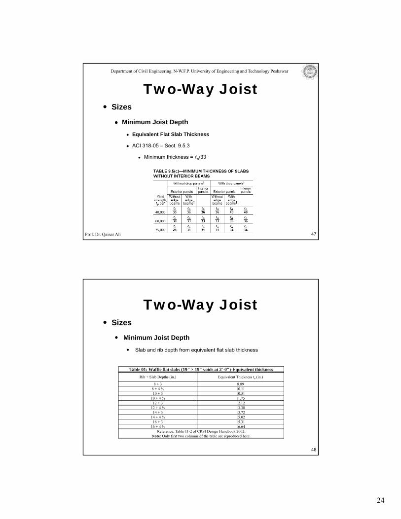
Equivalent Flat Slab Thickness
ACI 318-05 – Sect. 9.5.3
Minimum thickness = ln/33
Prof. Dr. Qaisar Ali 47
Sizes
Minimum Joist Depth
Two-Way Joist
Minimum Joist Depth
Slab and rib depth from equivalent flat slab thickness
Table 01: Waffle flat slabs (19" × 19" voids at 2'-0")-Equivalent thicknessRib + Slab Depths (in.) Equivalent Thickness te (in.)
8 + 3 8.898 + 4 ½ 10.1110 + 3 10.51
48
10 + 4 ½ 11.7512 + 3 12.12
12 + 4 ½ 13.3814 + 3 13.72
14 + 4 ½ 15.0216 + 3 15.31
16 + 4 ½ 16.64Reference: Table 11-2 of CRSI Design Handbook 2002.
Note: Only first two columns of the table are reproduced here.
25
Sizes
Minimum Joist Depth
Two-Way Joist
Minimum Joist Depth
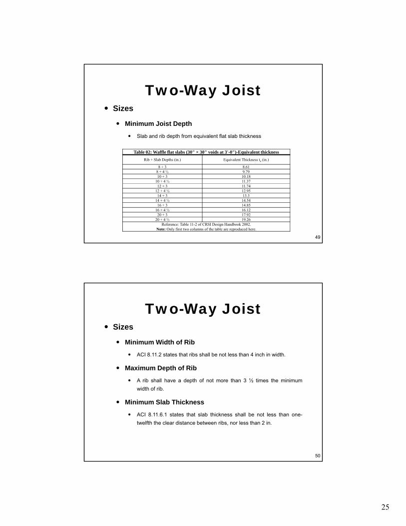
Slab and rib depth from equivalent flat slab thickness
Table 02: Waffle flat slabs (30" × 30" voids at 3'-0")-Equivalent thicknessRib + Slab Depths (in.) Equivalent Thickness te (in.)
8 + 3 8.618 + 4 ½ 9.7910 + 3 10.18
10 + 4 ½ 11.37
49
12 + 3 11.7412 + 4 ½ 12.9514 + 3 13.3
14 + 4 ½ 14.5416 + 3 14.85
16 + 4 ½ 16.1220 + 3 17.92
20 + 4 ½ 19.26Reference: Table 11-2 of CRSI Design Handbook 2002.
Note: Only first two columns of the table are reproduced here.
Sizes
Minimum Width of Rib
Two-Way Joist
Minimum Width of Rib
ACI 8.11.2 states that ribs shall be not less than 4 inch in width.
Maximum Depth of Rib
A rib shall have a depth of not more than 3 ½ times the minimumwidth of rib.
Minimum Slab Thickness
50
Minimum Slab Thickness
ACI 8.11.6.1 states that slab thickness shall be not less than one-twelfth the clear distance between ribs, nor less than 2 in.
26
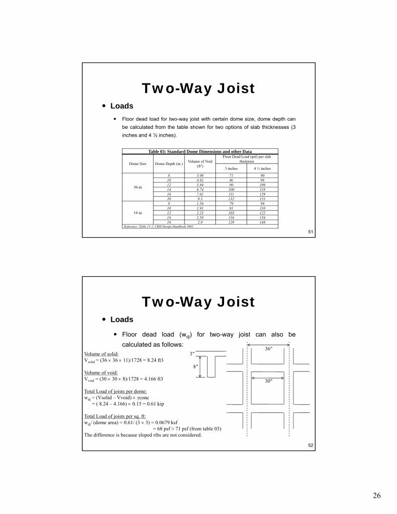
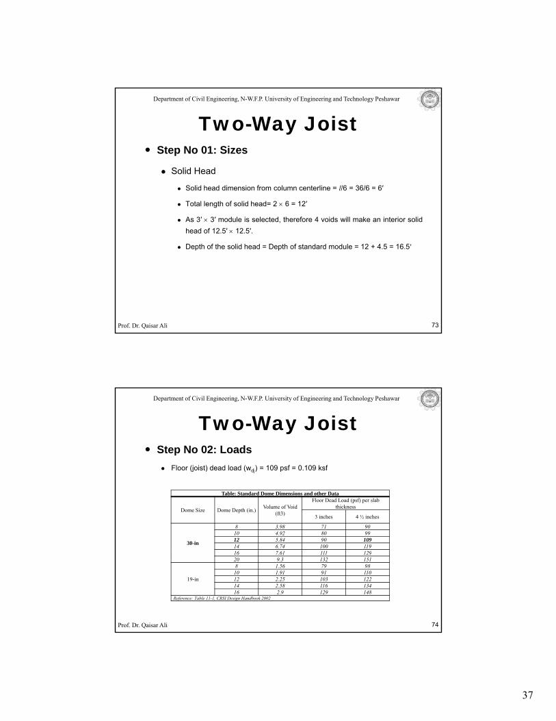
LoadsFloor dead load for two-way joist with certain dome size, dome depth can
Two-Way Joist
y j , pbe calculated from the table shown for two options of slab thicknesses (3inches and 4 ½ inches).
Table 03: Standard Dome Dimensions and other Data
Dome Size Dome Depth (in.) Volume of Void (ft3)
Floor Dead Load (psf) per slab thickness
3 inches 4 ½ inches
8 3.98 71 9010 4 92 80 99
51
30-in
10 4.92 80 9912 5.84 90 10914 6.74 100 11916 7.61 111 12920 9.3 132 151
19-in
8 1.56 79 9810 1.91 91 11012 2.25 103 12214 2.58 116 13416 2.9 129 148
Reference: Table 11-1, CRSI Design Handbook 2002
Loads
Floor dead load (w ) for two way joist can also be
Two-Way Joist
Floor dead load (wdj) for two-way joist can also becalculated as follows:
36″
8″
3″
30″
Volume of solid:Vsolid = (36 × 36 × 11)/1728 = 8.24 ft3
Volume of void:Vvoid = (30 × 30 × 8)/1728 = 4.166 ft3
Total Load of joists per dome:
52
Total Load of joists per dome:wdj = (Vsolid – Vvoid) × γconc
= ( 8.24 – 4.166) × 0.15 = 0.61 kip
Total Load of joists per sq. ft:wdj/ (dome area) = 0.61/ (3 × 3) = 0.0679 ksf
= 68 psf ≈ 71 psf (from table 03)The difference is because sloped ribs are not considered.
27
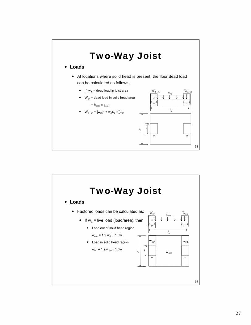
Loads
At locations where solid head is present the floor dead load
Two-Way Joist
At locations where solid head is present, the floor dead loadcan be calculated as follows:
If, wdj = dead load in joist area
Wsh = dead load in solid head area
= hsolid × γconc
Wdj+sh = {wshb + wdj(l2-b)}/l2
wdjWdj+sh
ln
a a
Wdj+sh
53
dj+sh { sh dj( 2 )} 2
bl2
a a
Loads
Factored loads can be calculated as:
Two-Way Joist
Factored loads can be calculated as:
If wL = live load (load/area), then
Load out of solid head region
wosh = 1.2 wdj + 1.6wL
Load in solid head region
1 2 1 6
wish wish
woshWish
ln
a a
Wish
54
wish = 1.2wdj+sh+1.6wL bl2
a awosh
28
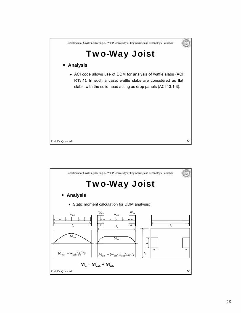
Department of Civil Engineering, N-W.F.P. University of Engineering and Technology Peshawar
Analysis
ACI code allows use of DDM for analysis of waffle slabs (ACI
Two-Way Joist
ACI code allows use of DDM for analysis of waffle slabs (ACIR13.1). In such a case, waffle slabs are considered as flatslabs, with the solid head acting as drop panels (ACI 13.1.3).
Prof. Dr. Qaisar Ali 55
Department of Civil Engineering, N-W.F.P. University of Engineering and Technology Peshawar
Analysis
Static moment calculation for DDM analysis:
Two-Way Joist
Static moment calculation for DDM analysis:
wosh
ln
woshWish
lna a
Wish
Mosh Mish
ln
Prof. Dr. Qaisar Ali 56
Mosh = woshl2ln2/8 Mish = (wish-wosh)ba2/2
Mish
Mo = Mosh + Mish
b
l2
a a
29
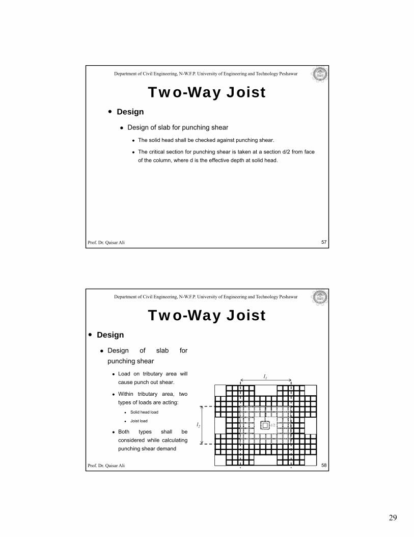
Department of Civil Engineering, N-W.F.P. University of Engineering and Technology Peshawar
Design
Design of slab for punching shear
Two-Way Joist
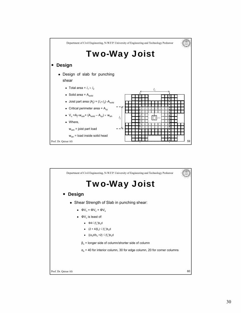
Design of slab for punching shear
The solid head shall be checked against punching shear.
The critical section for punching shear is taken at a section d/2 from faceof the column, where d is the effective depth at solid head.
Prof. Dr. Qaisar Ali 57
Department of Civil Engineering, N-W.F.P. University of Engineering and Technology Peshawar
Design
Design of slab for
Two-Way Joist
Design of slab forpunching shear
Load on tributary area willcause punch out shear.
Within tributary area, twotypes of loads are acting:
l1
Prof. Dr. Qaisar Ali
Solid head load
Joist load
Both types shall beconsidered while calculatingpunching shear demand
58
l2 d/2
30
Department of Civil Engineering, N-W.F.P. University of Engineering and Technology Peshawar
Design
Design of slab for punching
Two-Way Joist
Design of slab for punchingshear
Total area = l1 × l2
Solid area = Asolid
Joist part area (Aj) = (l1×l2) -Asolid
Critical perimeter area = Acp
l1
Prof. Dr. Qaisar Ali
Critical perimeter area Acp
Vu =Aj×wosh+ (Asolid – Acp) × wish
Where,
wosh = joist part load
wish = load inside solid head
59
l2 d/2
Department of Civil Engineering, N-W.F.P. University of Engineering and Technology Peshawar
DesignShear Strength of Slab in punching shear:
Two-Way Joist
Shear Strength of Slab in punching shear:
ΦVn = ΦVc + ΦVs
ΦVc is least of:
Φ4√ (fc′)bod
(2 + 4/βc) √ (fc′)bod
{(αsd/bo +2} √ (fc′)bod
Prof. Dr. Qaisar Ali 60
βc = longer side of column/shorter side of column
αs = 40 for interior column, 30 for edge column, 20 for corner columns
31
Department of Civil Engineering, N-W.F.P. University of Engineering and Technology Peshawar
DesignDesign of Joist for Beam Shear:
Two-Way Joist
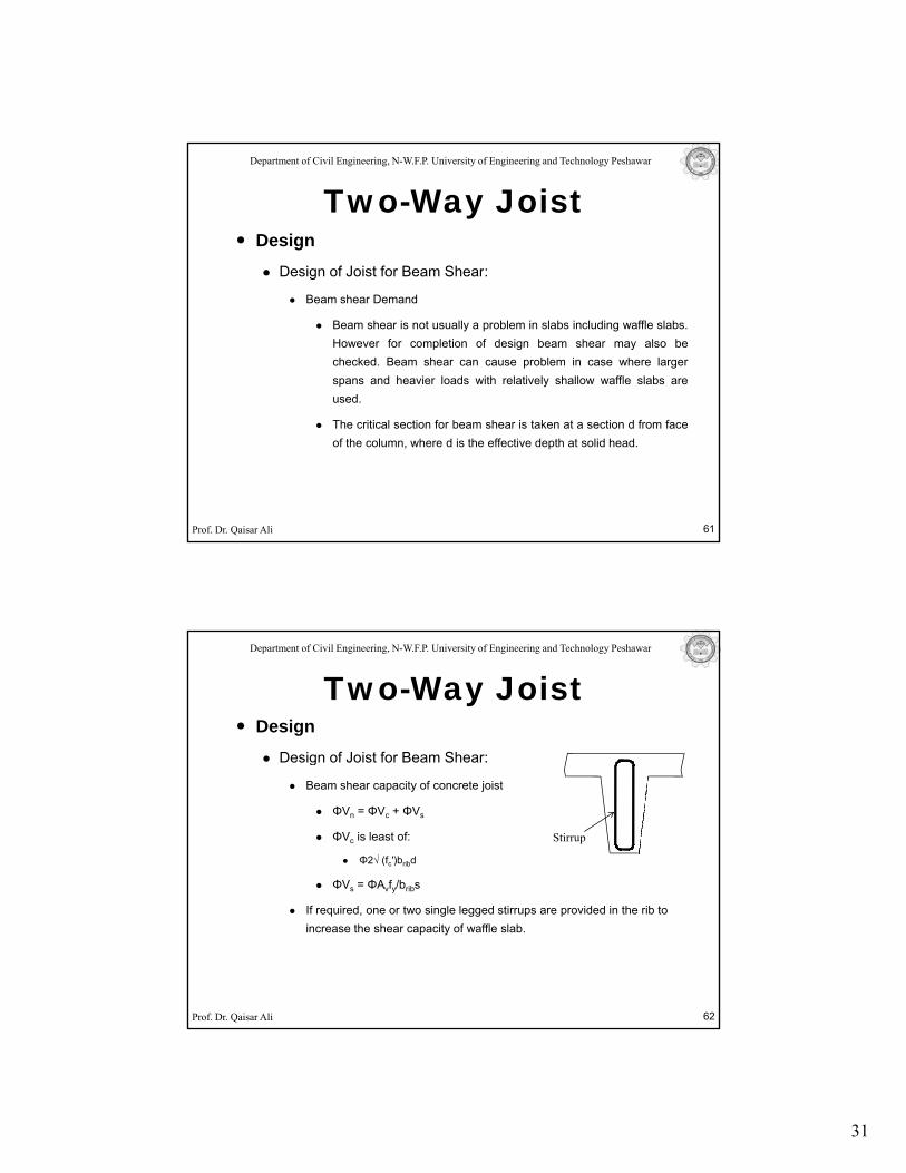
Design of Joist for Beam Shear:
Beam shear Demand
Beam shear is not usually a problem in slabs including waffle slabs.However for completion of design beam shear may also bechecked. Beam shear can cause problem in case where largerspans and heavier loads with relatively shallow waffle slabs areused.
Prof. Dr. Qaisar Ali 61
The critical section for beam shear is taken at a section d from faceof the column, where d is the effective depth at solid head.
Department of Civil Engineering, N-W.F.P. University of Engineering and Technology Peshawar
DesignDesign of Joist for Beam Shear:
Two-Way Joist
g
Beam shear capacity of concrete joist
ΦVn = ΦVc + ΦVs
ΦVc is least of:
Φ2√ (fc′)bribd
ΦVs = ΦAvfy/bribs
Stirrup
Prof. Dr. Qaisar Ali 62
If required, one or two single legged stirrups are provided in the rib to increase the shear capacity of waffle slab.
32
Department of Civil Engineering, N-W.F.P. University of Engineering and Technology Peshawar
Design
Design for Flexure
Two-Way Joist
Design for Flexure
The design of waffle slab is done by usual procedures.
However, certain reinforcement requirements apply discussed next.
Prof. Dr. Qaisar Ali 63
Department of Civil Engineering, N-W.F.P. University of Engineering and Technology Peshawar
ACI recommendations on reinforcement requirement of waffle slab:
Two-Way Joist
requirement of waffle slab:
ACI 10.6.7 states that if the effective depth d of a beam orjoist exceeds 36 in., longitudinal skin reinforcement shall beprovided as per ACI section 10.6.7.
According to ACI 13.3.2, for cellular or ribbed constructionreinforcement shall not be less than the requirements of ACI
Prof. Dr. Qaisar Ali
reinforcement shall not be less than the requirements of ACI7.12.
As per ACI 7.12, Spacing of top bars cannot exceed 5h or18 inches.
64
33
Department of Civil Engineering, N-W.F.P. University of Engineering and Technology Peshawar
ACI recommendations on reinforcement requirement of waffle slab:
Two-Way Joist
requirement of waffle slab:
Prof. Dr. Qaisar Ali 65
Department of Civil Engineering, N-W.F.P. University of Engineering and Technology Peshawar
Other important points:
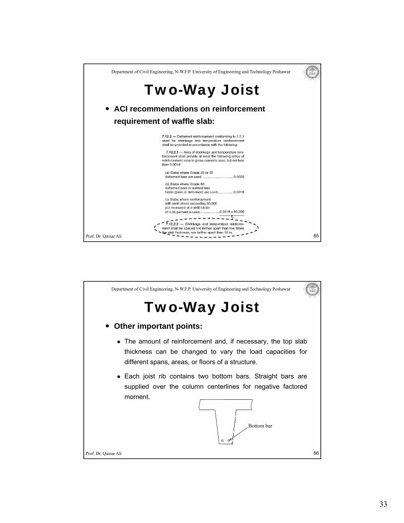
The amount of reinforcement and if necessary the top slab
Two-Way Joist
The amount of reinforcement and, if necessary, the top slabthickness can be changed to vary the load capacities fordifferent spans, areas, or floors of a structure.
Each joist rib contains two bottom bars. Straight bars aresupplied over the column centerlines for negative factoredmoment.
Prof. Dr. Qaisar Ali 66
Bottom bar
34
Department of Civil Engineering, N-W.F.P. University of Engineering and Technology Peshawar
Other important points:
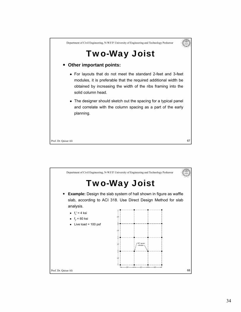
For layouts that do not meet the standard 2 feet and 3 feet
Two-Way Joist
For layouts that do not meet the standard 2-feet and 3-feetmodules, it is preferable that the required additional width beobtained by increasing the width of the ribs framing into thesolid column head.
The designer should sketch out the spacing for a typical paneland correlate with the column spacing as a part of the early
Prof. Dr. Qaisar Ali
p g p yplanning.
67
Department of Civil Engineering, N-W.F.P. University of Engineering and Technology Peshawar
Example: Design the slab system of hall shown in figure as waffleslab, according to ACI 318. Use Direct Design Method for slab
Two-Way Joist
analysis.fc′ = 4 ksi
fy = 60 ksi
Live load = 100 psf
Prof. Dr. Qaisar Ali 68
35
Department of Civil Engineering, N-W.F.P. University of Engineering and Technology Peshawar
Solution:A 108′ × 144′ building divided into twelve (12) panels supported at
Two-Way Joist
A 108 × 144 building, divided into twelve (12) panels, supported attheir ends on columns. Each panel is 36′ × 36′.
The given slab system satisfies all the necessary limitations for DirectDesign Method to be applicable.
Prof. Dr. Qaisar Ali 69
Department of Civil Engineering, N-W.F.P. University of Engineering and Technology Peshawar
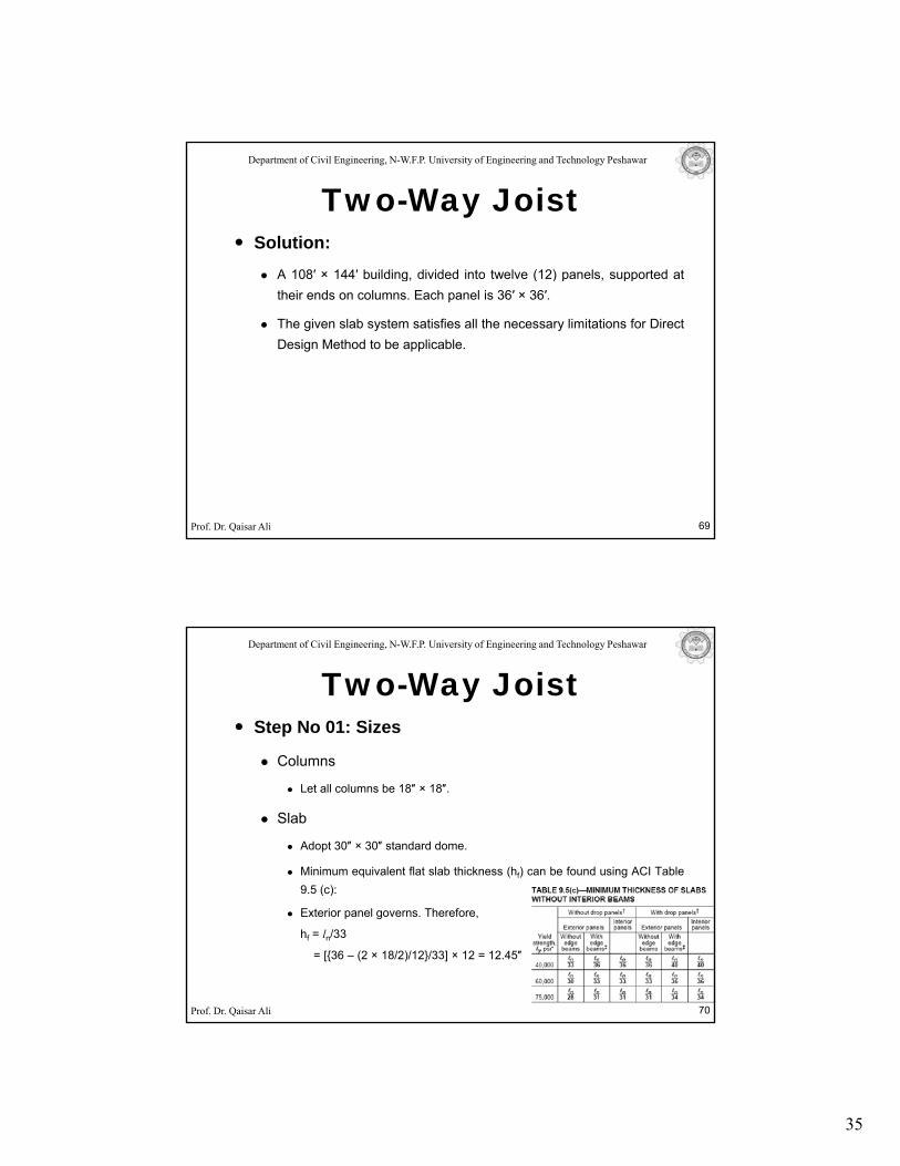
Step No 01: Sizes
Columns
Two-Way Joist
Columns
Let all columns be 18″ × 18″.
Slab
Adopt 30″ × 30″ standard dome.
Minimum equivalent flat slab thickness (hf) can be found using ACI Table9 5 (c):
Prof. Dr. Qaisar Ali
9.5 (c):
Exterior panel governs. Therefore,
hf = ln/33
= [{36 – (2 × 18/2)/12}/33] × 12 = 12.45″
70
36
Department of Civil Engineering, N-W.F.P. University of Engineering and Technology Peshawar
Step No 01: Sizes
Slab
Two-Way Joist
Slab
The closest depth of doom that will fulfill the requirement of equivalentthickness of flat slab equal to 12.45″ is 12 in. with a slab thickness of 4 ½in. for a dome size of 30-in.
Table: Waffle flat slabs (30" × 30" voids at 3'-0")-Equivalent thickness
Rib + Slab Depths (in.) Equivalent Thickness te (in.)
8 + 3 8.618 + 4 ½ 9.79
Prof. Dr. Qaisar Ali 71
10 + 3 10.1810 + 4 ½ 11.3712 + 3 11.74
12 + 4 ½ 12.9514 + 3 13.3
14 + 4 ½ 14.5416 + 3 14.85
16 + 4 ½ 16.1220 + 3 17.92
20 + 4 ½ 19.26Reference: Table 11-2 of CRSI Design Handbook 2002.
Note: Only first two columns of the table are reproduced here.
Department of Civil Engineering, N-W.F.P. University of Engineering and Technology Peshawar
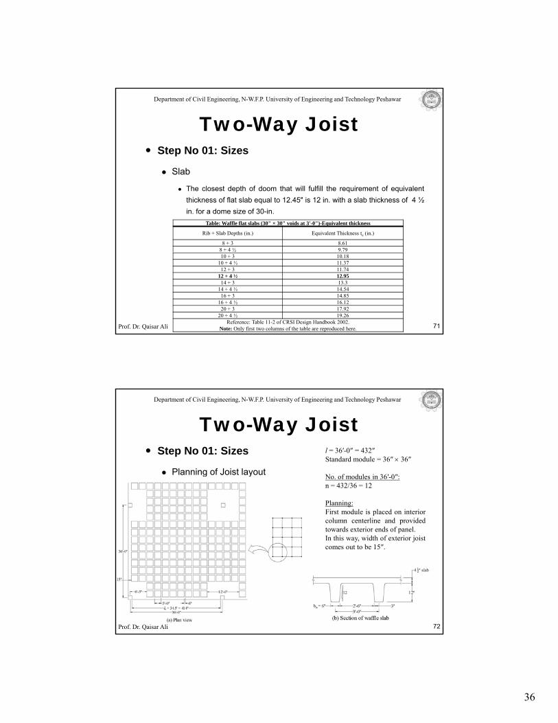
Step No 01: Sizes
Planning of Joist layout
Two-Way Joistl = 36′-0″ = 432″Standard module = 36″ × 36″
Planning of Joist layout No. of modules in 36′-0″:n = 432/36 = 12
Planning:First module is placed on interiorcolumn centerline and providedtowards exterior ends of panel.In this way, width of exterior joistcomes out to be 15″.
Prof. Dr. Qaisar Ali 72
37
Department of Civil Engineering, N-W.F.P. University of Engineering and Technology Peshawar
Step No 01: Sizes
Solid Head
Two-Way Joist
Solid Head
Solid head dimension from column centerline = l/6 = 36/6 = 6′
Total length of solid head= 2 × 6 = 12′
As 3′ × 3′ module is selected, therefore 4 voids will make an interior solidhead of 12.5′ × 12.5′.
Depth of the solid head = Depth of standard module = 12 + 4.5 = 16.5′
Prof. Dr. Qaisar Ali 73
Department of Civil Engineering, N-W.F.P. University of Engineering and Technology Peshawar
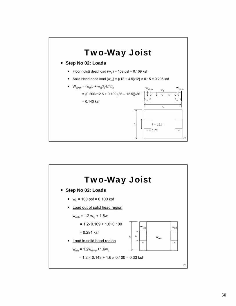
Step No 02: LoadsFloor (joist) dead load (wdj) = 109 psf = 0 109 ksf
Two-Way Joist
Floor (joist) dead load (wdj) 109 psf 0.109 ksf
Table: Standard Dome Dimensions and other Data
Dome Size Dome Depth (in.) Volume of Void (ft3)
Floor Dead Load (psf) per slab thickness
3 inches 4 ½ inches
30-in
8 3.98 71 9010 4.92 80 9912 5.84 90 10914 6.74 100 11916 61 111 129
Prof. Dr. Qaisar Ali 74
16 7.61 111 12920 9.3 132 151
19-in
8 1.56 79 9810 1.91 91 11012 2.25 103 12214 2.58 116 13416 2.9 129 148
Reference: Table 11-1, CRSI Design Handbook 2002
38
Step No 02: LoadsFloor (joist) dead load (wdj) = 109 psf = 0 109 ksf
Two-Way Joist
Floor (joist) dead load (wdj) 109 psf 0.109 ksf
Solid Head dead load (wsh) = {(12 + 4.5)/12} × 0.15 = 0.206 ksf
Wdj+sh = {wshb + wdj(l2-b)}/l2
= {0.206×12.5 + 0.109 (36 – 12.5)}/36
= 0.143 ksf
wdjWdj+sh
l
a a
Wdj+sh
75
ln
b = 12.5′l2
a = 5.25′ a
Step No 02: Loads
w = 100 psf = 0 100 ksf
Two-Way Joist
wL = 100 psf = 0.100 ksf
Load out of solid head region
wosh = 1.2 wdj + 1.6wL
= 1.2×0.109 + 1.6×0.100
= 0.291 ksfwish wish
76
Load in solid head region
wish = 1.2wdj+sh+1.6wL
= 1.2 × 0.143 + 1.6 × 0.100 = 0.33 ksf
bl2
a awosh
Department of Civil Engineering, N-W.F.P. University of Engineering and Technology Peshawar
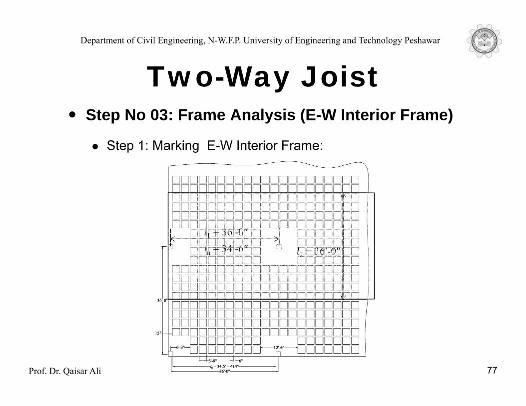
Two Way JoistStep No 03: Frame Analysis (E-W Interior Frame)
Two-Way Joist
Step 1: Marking E-W Interior Frame:
l 36′ 0″
l2 = 36′-0″
l1 = 36′-0″ln = 34′-6″
Prof. Dr. Qaisar Ali 77

Department of Civil Engineering, N-W.F.P. University of Engineering and Technology Peshawar
Two Way JoistStep No 03: Frame Analysis (E-W Interior Frame)
Two-Way Joist
Step 01: Marking E-W Interior Frame
Design Span of frame (c/c) = l1 = 36′
Design Length of frame = ln = 36 – (2 × 18/2)/12 = 34.5′
Width of frame = l2 = 36′
Half column strip width = (Shorter span)/ 4 = 36/4 = 9′
Prof. Dr. Qaisar Ali 78
Department of Civil Engineering, N-W.F.P. University of Engineering and Technology Peshawar
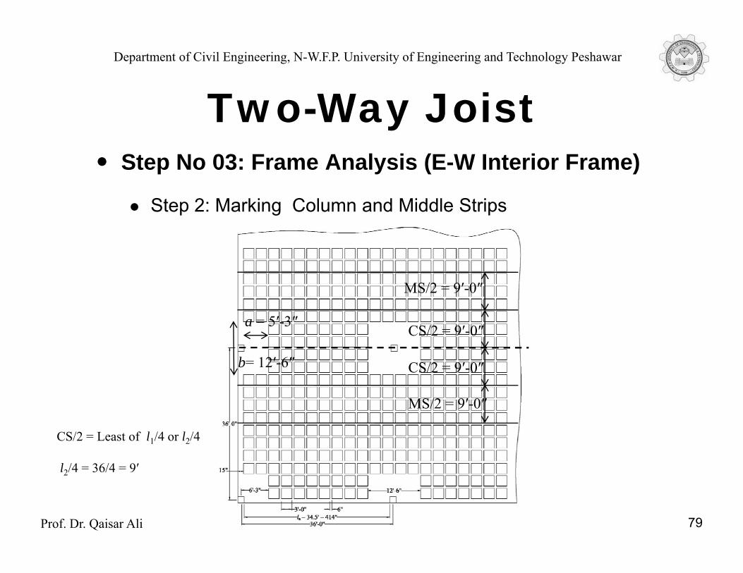
Two Way JoistStep No 03: Frame Analysis (E-W Interior Frame)
Two-Way Joist
Step 2: Marking Column and Middle Strips
MS/2 = 9′-0″
a = 5′-3″ CS/2 = 9′-0″
CS/2 = 9′-0″
a 5 -3
b= 12′-6″
CS/2 = Least of l1/4 or l2/4
l /4 = 36/4 = 9′
MS/2 = 9′-0″
Prof. Dr. Qaisar Ali 79
l2/4 = 36/4 = 9
Department of Civil Engineering, N-W.F.P. University of Engineering and Technology Peshawar
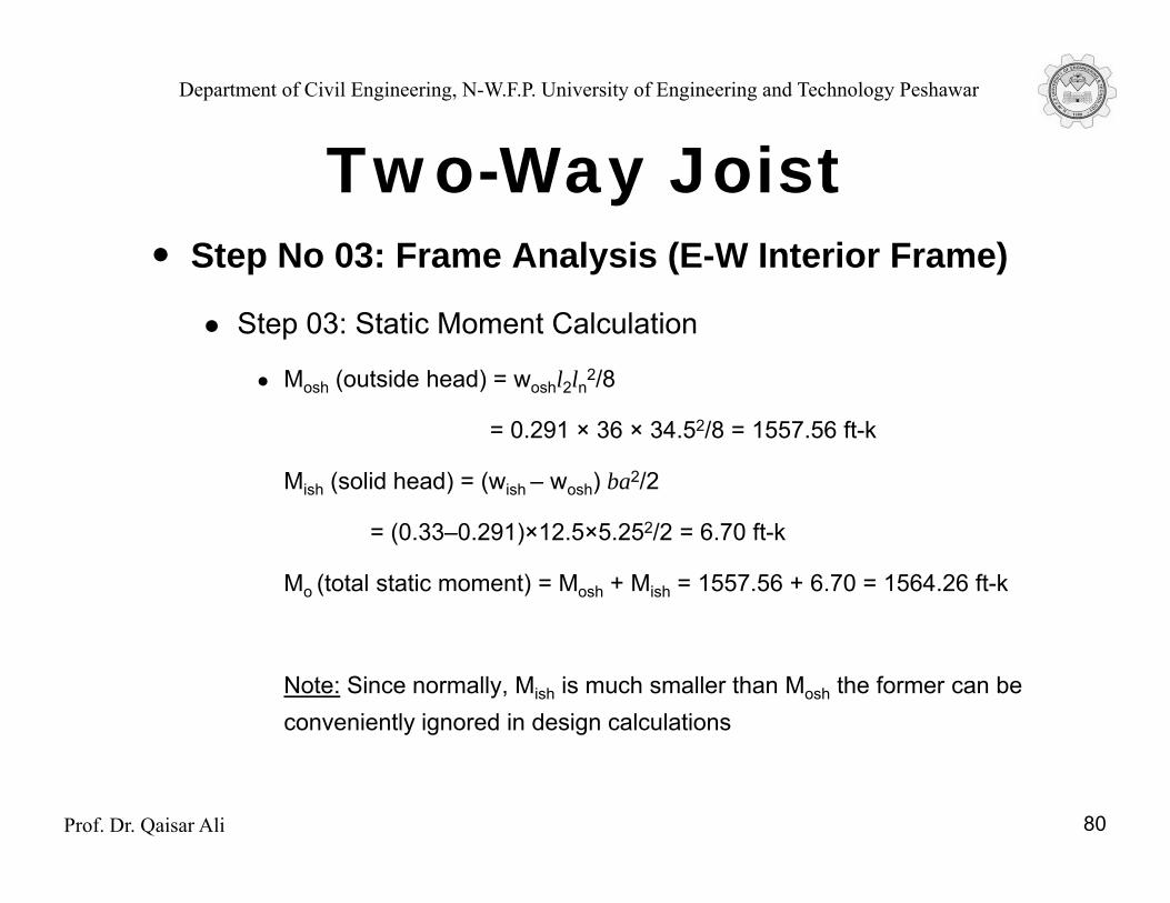
Two Way JoistStep No 03: Frame Analysis (E-W Interior Frame)
Two-Way Joist
Step 03: Static Moment Calculation
Mosh (outside head) = woshl2ln2/8
= 0.291 × 36 × 34.52/8 = 1557.56 ft-k
Mish (solid head) = (wish – wosh) ba2/2
= (0.33–0.291)×12.5×5.252/2 = 6.70 ft-k
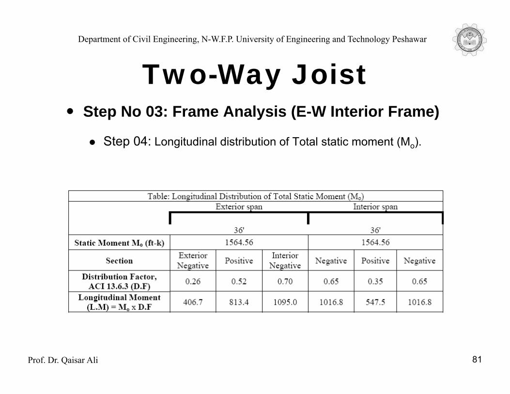
Mo (total static moment) = Mosh + Mish = 1557.56 + 6.70 = 1564.26 ft-k
Note: Since normally, Mish is much smaller than Mosh the former can be conveniently ignored in design calculations
Prof. Dr. Qaisar Ali 80
Department of Civil Engineering, N-W.F.P. University of Engineering and Technology Peshawar
Two Way JoistStep No 03: Frame Analysis (E-W Interior Frame)
Two-Way Joist
Step 04: Longitudinal distribution of Total static moment (Mo).
Prof. Dr. Qaisar Ali 81
Department of Civil Engineering, N-W.F.P. University of Engineering and Technology Peshawar
Two Way JoistStep No 03: Frame Analysis (E-W Interior Frame)
Two-Way Joist
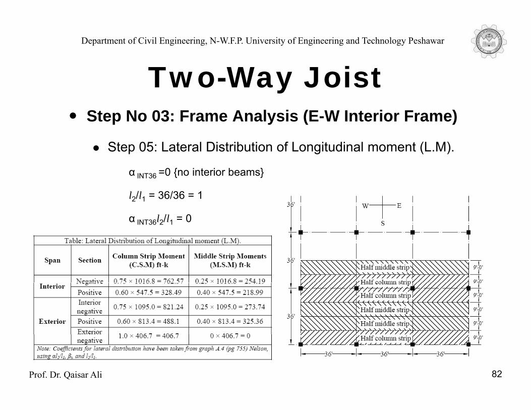
Step 05: Lateral Distribution of Longitudinal moment (L.M).
α INT36 =0 {no interior beams}
l2/l1 = 36/36 = 1
α INT36l2/l1 = 0
Prof. Dr. Qaisar Ali 82
Department of Civil Engineering, N-W.F.P. University of Engineering and Technology Peshawar
Two Way JoistStep No 03: Frame Analysis (E-W Exterior Frame)
Two-Way Joist
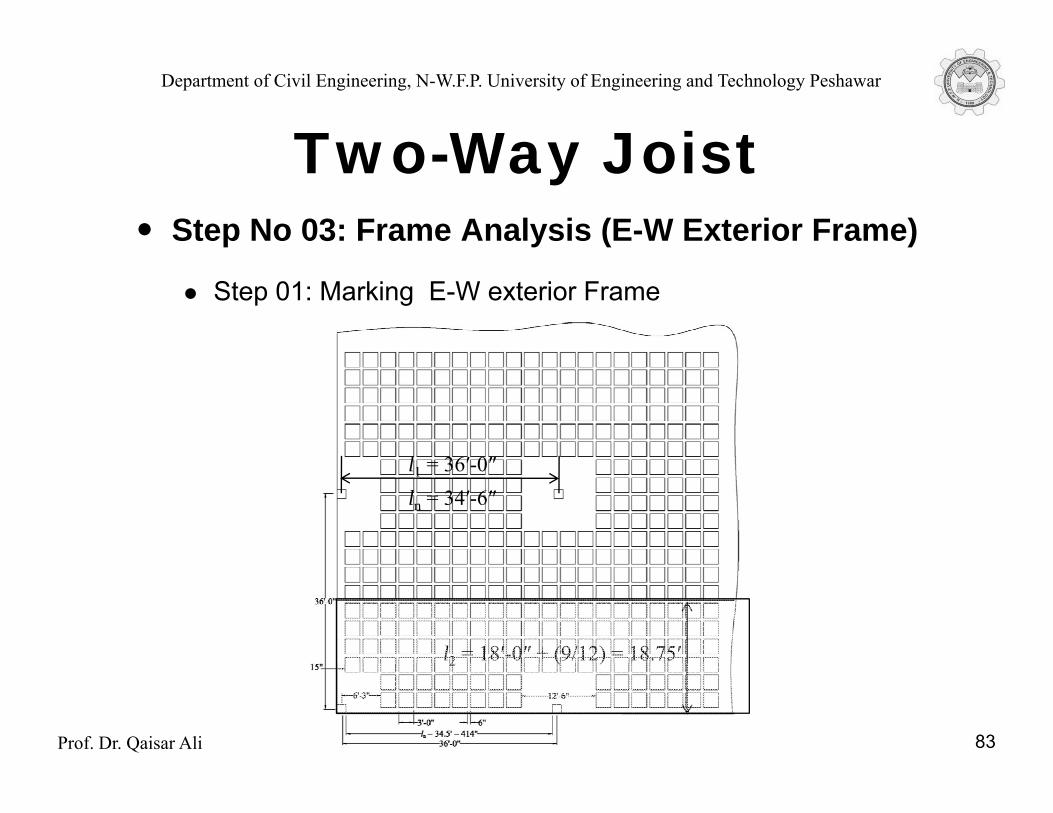
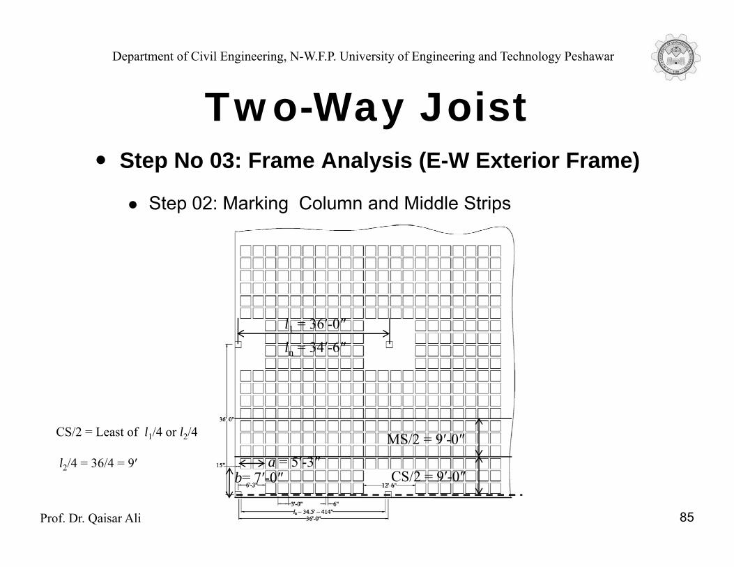
Step 01: Marking E-W exterior Frame
l 36′ 0″l1 = 36′-0″ln = 34′-6″
l2 = 18′-0″ + (9/12) = 18.75′
Prof. Dr. Qaisar Ali 83
2 ( )
Department of Civil Engineering, N-W.F.P. University of Engineering and Technology Peshawar
Two Way JoistStep No 03: Frame Analysis (E-W Exterior Frame)
Two-Way Joist
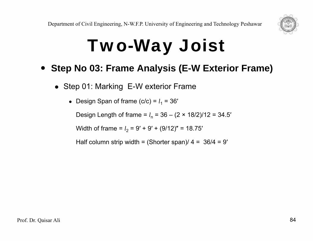
Step 01: Marking E-W exterior Frame
Design Span of frame (c/c) = l1 = 36′
Design Length of frame = ln = 36 – (2 × 18/2)/12 = 34.5′
Width of frame = l2 = 9′ + 9′ + (9/12)″ = 18.75′
Half column strip width = (Shorter span)/ 4 = 36/4 = 9′
Prof. Dr. Qaisar Ali 84
Department of Civil Engineering, N-W.F.P. University of Engineering and Technology Peshawar
Two Way JoistStep No 03: Frame Analysis (E-W Exterior Frame)
Two-Way Joist
Step 02: Marking Column and Middle Strips
l 36′ 0″l1 = 36′-0″ln = 34′-6″
CS/2 = Least of l1/4 or l2/4
l /4 = 36/4 = 9′
MS/2 = 9′-0″a = 5′ 3″
Prof. Dr. Qaisar Ali 85
CS/2 = 9′-0″l2/4 = 36/4 = 9 a = 5 -3
b= 7′-0″

Department of Civil Engineering, N-W.F.P. University of Engineering and Technology Peshawar
Two Way JoistStep No 03: Frame Analysis (E-W Exterior Frame)
Two-Way Joist
Step 03: Static Moment Calculation
Mosh (outside head) = woshl2ln2/8
= 0.291 × 18.75 × 34.52/8 = 811.78 ft-k
Mish (solid head) = (wish – wosh) ba2/2
= (0.33–0.291)×7×5.252/2 = 3.76 ft-k
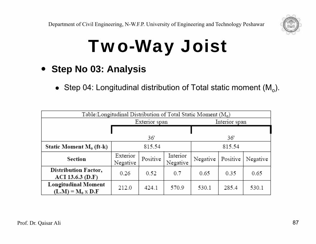
Mo (total static moment) = Mosh + Mish = 811.78 + 3.76 = 815.54 ft-k
Note: Since normally, Mish is much smaller than Mosh the former can be conveniently ignored in design calculations
Prof. Dr. Qaisar Ali 86
Department of Civil Engineering, N-W.F.P. University of Engineering and Technology Peshawar
Two Way JoistStep No 03: Analysis
Two-Way Joist
Step 04: Longitudinal distribution of Total static moment (Mo).
Prof. Dr. Qaisar Ali 87
Department of Civil Engineering, N-W.F.P. University of Engineering and Technology Peshawar
Two Way JoistStep No 03: Analysis
Two-Way Joist
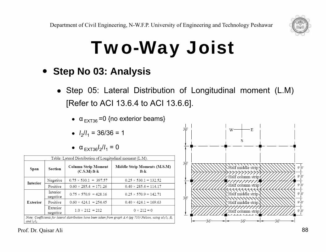
Step 05: Lateral Distribution of Longitudinal moment (L.M)[Refer to ACI 13.6.4 to ACI 13.6.6].
α EXT36 =0 {no exterior beams}
l2/l1 = 36/36 = 1
α EXT36l2/l1 = 0
Prof. Dr. Qaisar Ali 88
Department of Civil Engineering, N-W.F.P. University of Engineering and Technology Peshawar
Two Way JoistStep No 03: Analysis
Two-Way Joist
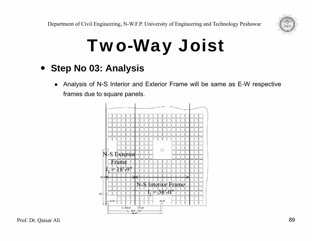
Analysis of N-S Interior and Exterior Frame will be same as E-W respectiveframes due to square panels.
N-S Exterior Frame
N-S Interior Framel2 = 36′-0″
l2 = 18′-9″
Prof. Dr. Qaisar Ali 89
Department of Civil Engineering, N-W.F.P. University of Engineering and Technology Peshawar
Two Way JoistStep No 04: Design
Two-Way Joist
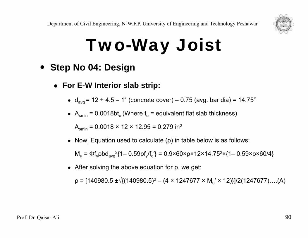
For E-W Interior slab strip:
davg = 12 + 4.5 – 1″ (concrete cover) – 0.75 (avg. bar dia) = 14.75″g
Asmin = 0.0018bte (Where te = equivalent flat slab thickness)
Asmin = 0.0018 × 12 × 12.95 = 0.279 in2
Now, Equation used to calculate (ρ) in table below is as follows:
Mu = Φfyρbdavg2{1– 0.59ρfy/fc′} = 0.9×60×ρ×12×14.752×{1– 0.59×ρ×60/4}
After solving the above equation for ρ, we get:
ρ = [140980.5 ±√{(140980.5)2 – (4 × 1247677 × Mu′ × 12)}]/2(1247677)….(A)
Prof. Dr. Qaisar Ali 90
Department of Civil Engineering, N-W.F.P. University of Engineering and Technology Peshawar
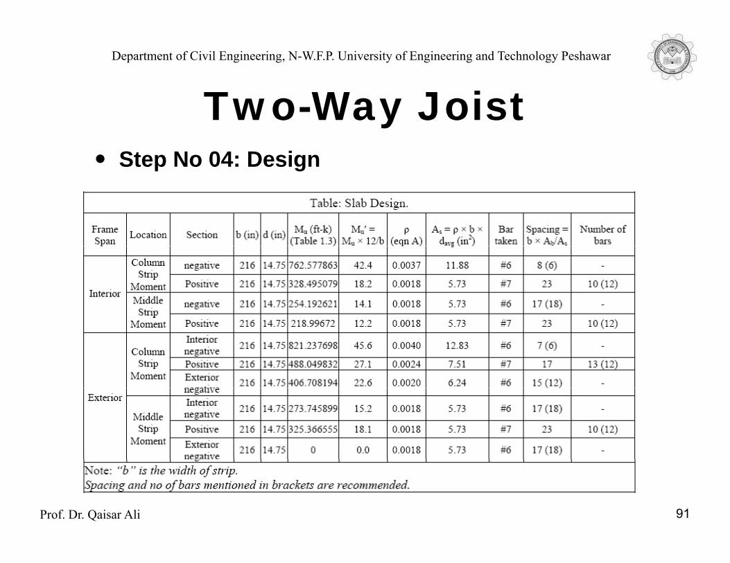
Two Way JoistStep No 04: Design
Two-Way Joist
For E-W Interior slab strip:
Prof. Dr. Qaisar Ali 91
Department of Civil Engineering, N-W.F.P. University of Engineering and Technology Peshawar
Two Way JoistStep No 04: Design
Two-Way Joist
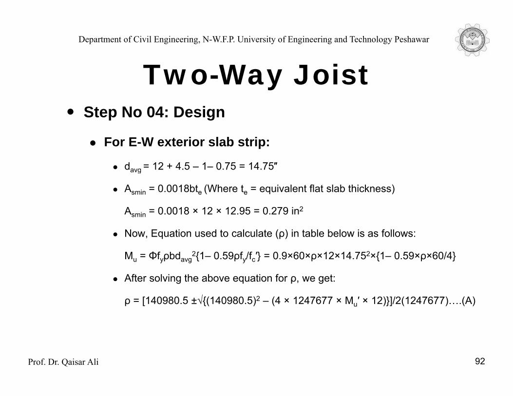
For E-W exterior slab strip:
davg = 12 + 4.5 – 1– 0.75 = 14.75″ g
Asmin = 0.0018bte (Where te = equivalent flat slab thickness)
Asmin = 0.0018 × 12 × 12.95 = 0.279 in2
Now, Equation used to calculate (ρ) in table below is as follows:
Mu = Φfyρbdavg2{1– 0.59ρfy/fc′} = 0.9×60×ρ×12×14.752×{1– 0.59×ρ×60/4}
After solving the above equation for ρ, we get:
ρ = [140980.5 ±√{(140980.5)2 – (4 × 1247677 × Mu′ × 12)}]/2(1247677)….(A)
Prof. Dr. Qaisar Ali 92
Department of Civil Engineering, N-W.F.P. University of Engineering and Technology Peshawar
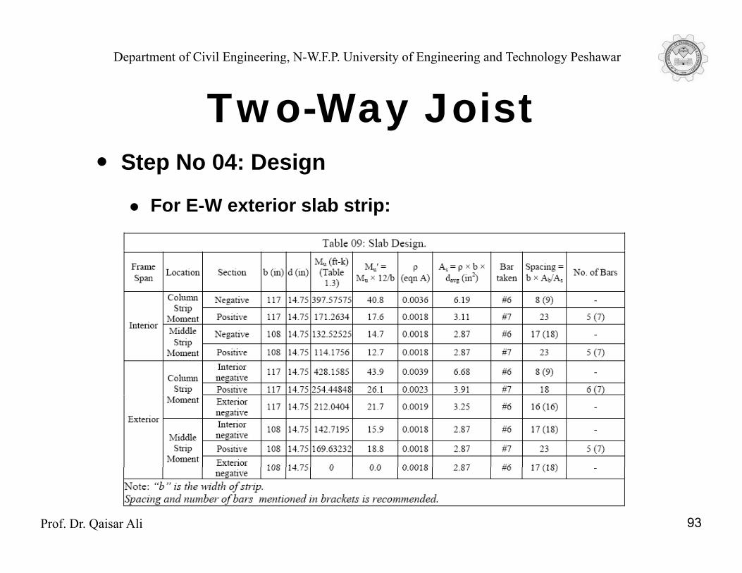
Two Way JoistStep No 04: Design
Two-Way Joist
For E-W exterior slab strip:
Prof. Dr. Qaisar Ali 93
Department of Civil Engineering, N-W.F.P. University of Engineering and Technology Peshawar
Two Way JoistStep No 04: Design
Two-Way Joist
Design of N-S Interior and Exterior Frame will be same as E-W respective frames due to square panels and also for thereason that davg is used in design.
Prof. Dr. Qaisar Ali 94
Department of Civil Engineering, N-W.F.P. University of Engineering and Technology Peshawar
Two Way JoistStep No 04: Design
Two-Way Joist
Note: For the completion of design problem, the waffle slabshould also be checked for beam shear and punching shear.
Prof. Dr. Qaisar Ali 95
Department of Civil Engineering, N-W.F.P. University of Engineering and Technology Peshawar
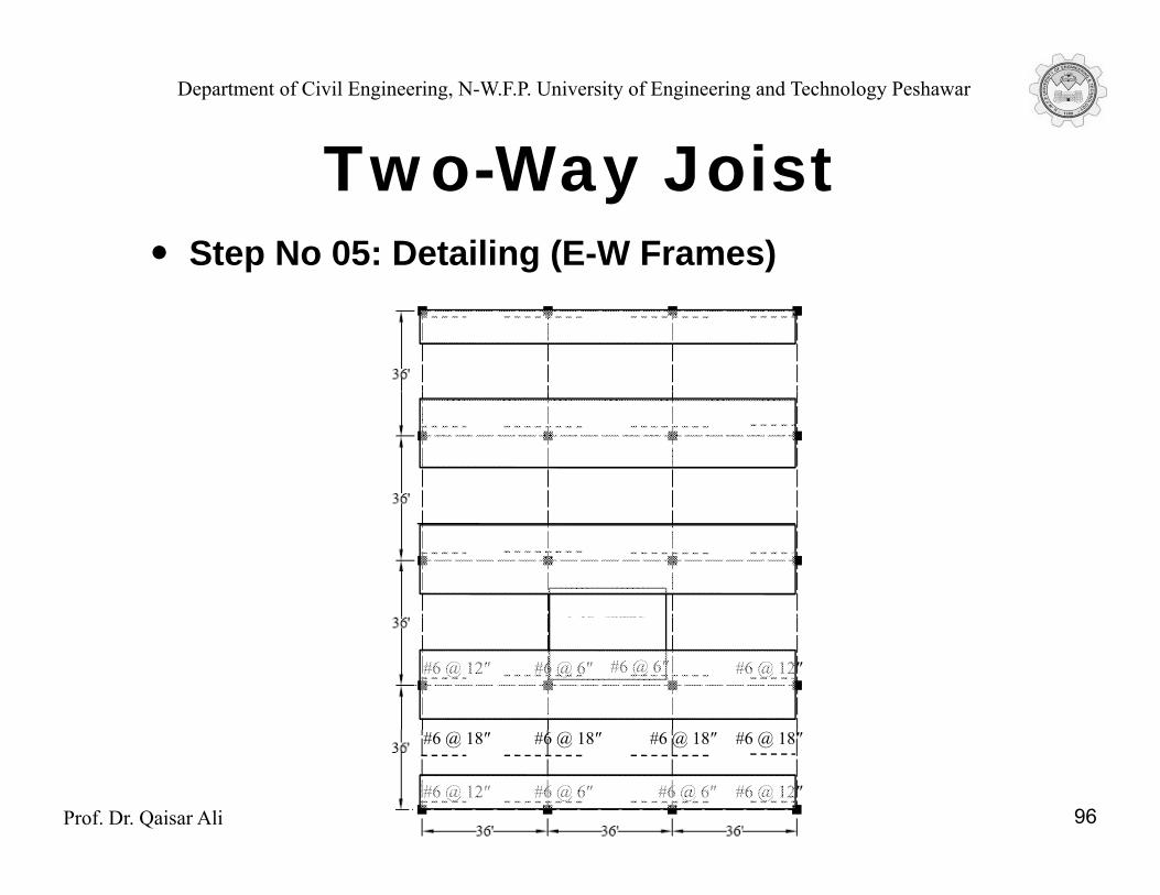
Two Way JoistStep No 05: Detailing (E-W Frames)
Two-Way Joist
#6 @ 12″ #6 @ 6″ #6 @ 6″ #6 @ 12″
Prof. Dr. Qaisar Ali 96#6 @ 12″ #6 @ 6″ #6 @ 6″ #6 @ 12″
#6 @ 18″ #6 @ 18″ #6 @ 18″ #6 @ 18″
Department of Civil Engineering, N-W.F.P. University of Engineering and Technology Peshawar
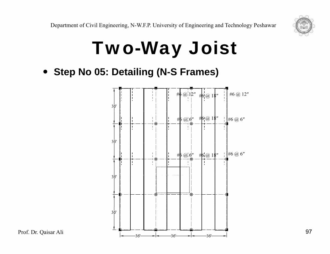
Two Way JoistStep No 05: Detailing (N-S Frames)
Two-Way Joist
#6 @ 12″#6 @ 18″#6 @ 12″
#6 @ 6″#6 @ 18″#6 @ 6″
#6 @ 6″#6 @ 18″#6 @ 6″
Prof. Dr. Qaisar Ali 97
Department of Civil Engineering, N-W.F.P. University of Engineering and Technology Peshawar
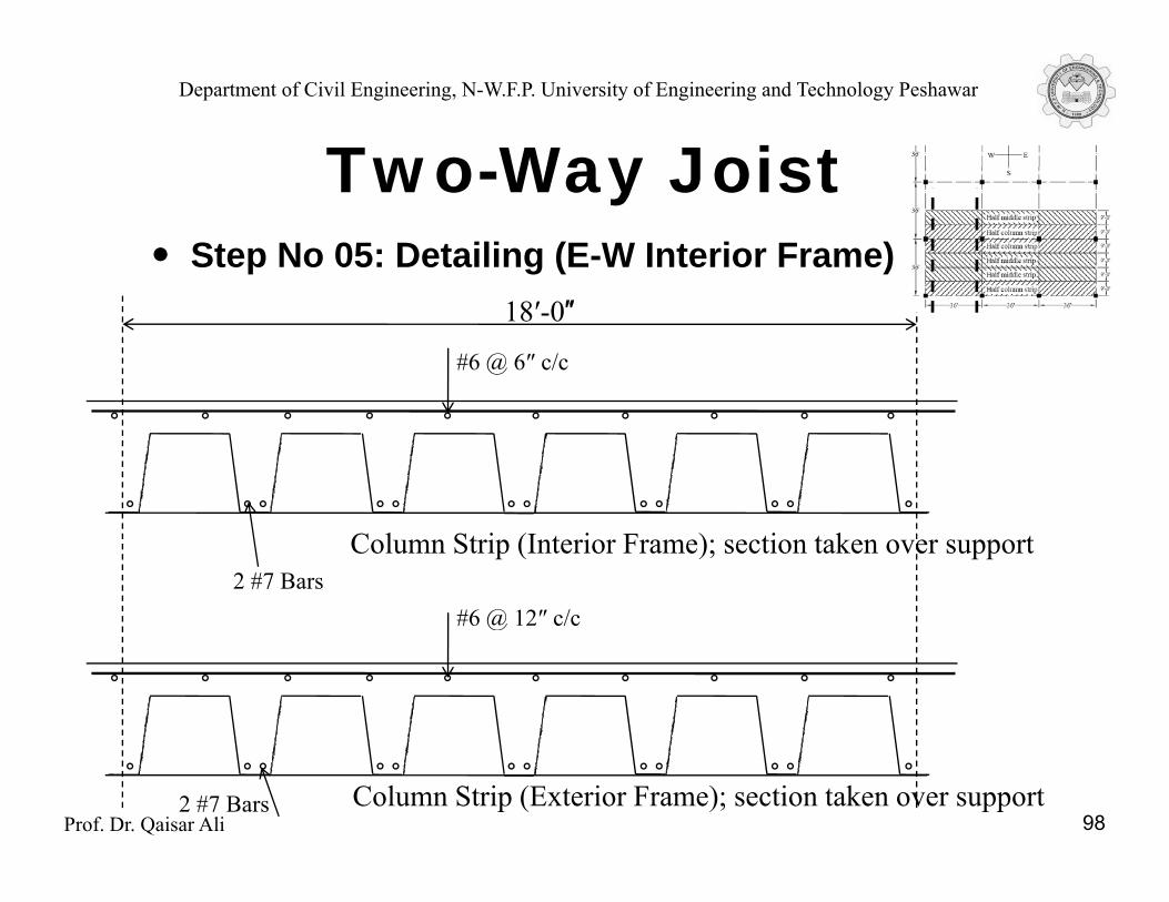
Two Way JoistStep No 05: Detailing (E-W Interior Frame)
Two-Way Joist
#6 @ 6″ c/c
18′-0″
Column Strip (Interior Frame); section taken over support
#6 @ 12″ c/c2 #7 Bars
#6 @ 12 c/c
Prof. Dr. Qaisar Ali 98Column Strip (Exterior Frame); section taken over support2 #7 Bars
Department of Civil Engineering, N-W.F.P. University of Engineering and Technology Peshawar
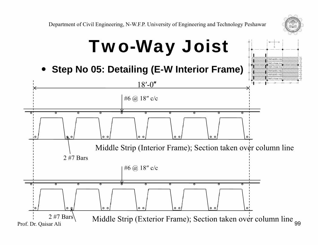
Two Way JoistStep No 05: Detailing (E-W Interior Frame)
Two-Way Joist
#6 @ 18″ c/c
18′-0″
Middle Strip (Interior Frame); Section taken over column line
#6 @ 18″ c/c2 #7 Bars
#6 @ 18 c/c
Prof. Dr. Qaisar Ali 99Middle Strip (Exterior Frame); Section taken over column line2 #7 Bars
Department of Civil Engineering, N-W.F.P. University of Engineering and Technology Peshawar
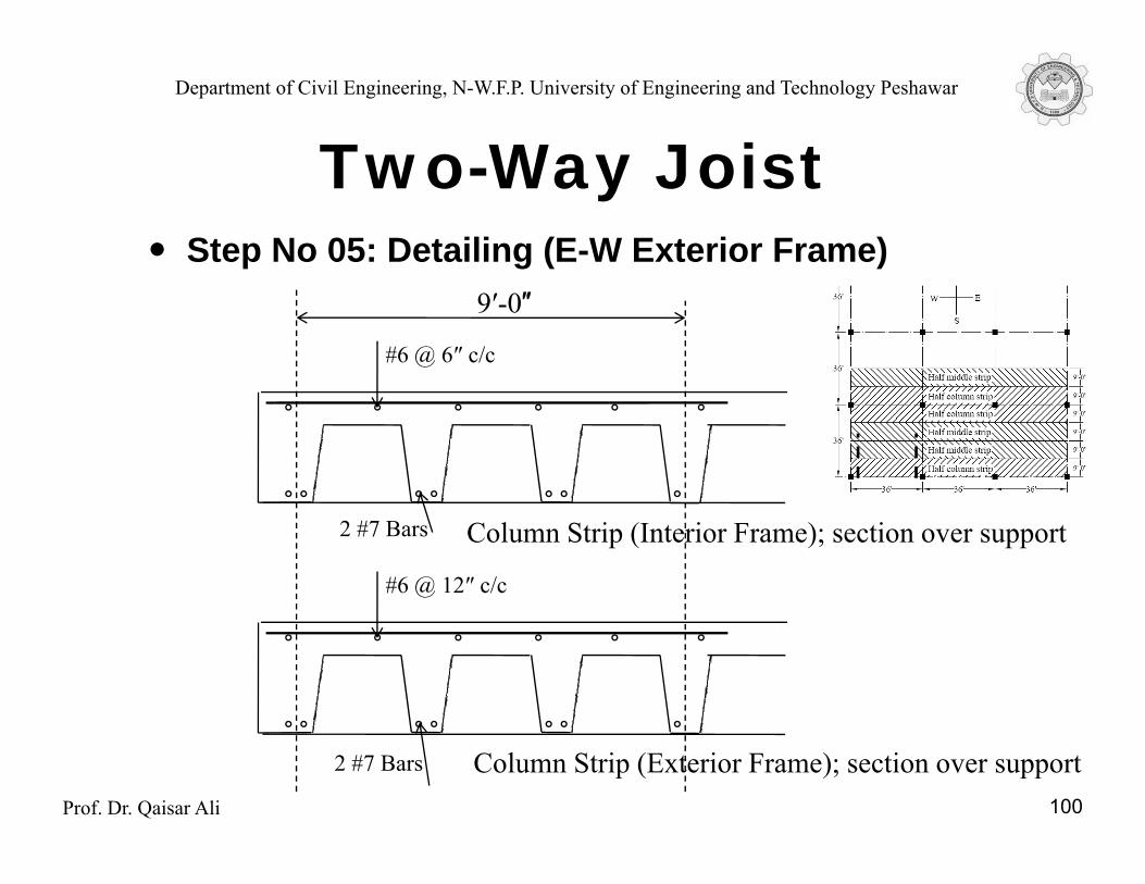
Two Way JoistStep No 05: Detailing (E-W Exterior Frame)
Two-Way Joist
#6 @ 6″ c/c
9′-0″
Column Strip (Interior Frame); section over support2 #7 Bars
#6 @ 12″ c/c
Prof. Dr. Qaisar Ali 100
Column Strip (Exterior Frame); section over support2 #7 Bars
Department of Civil Engineering, N-W.F.P. University of Engineering and Technology Peshawar
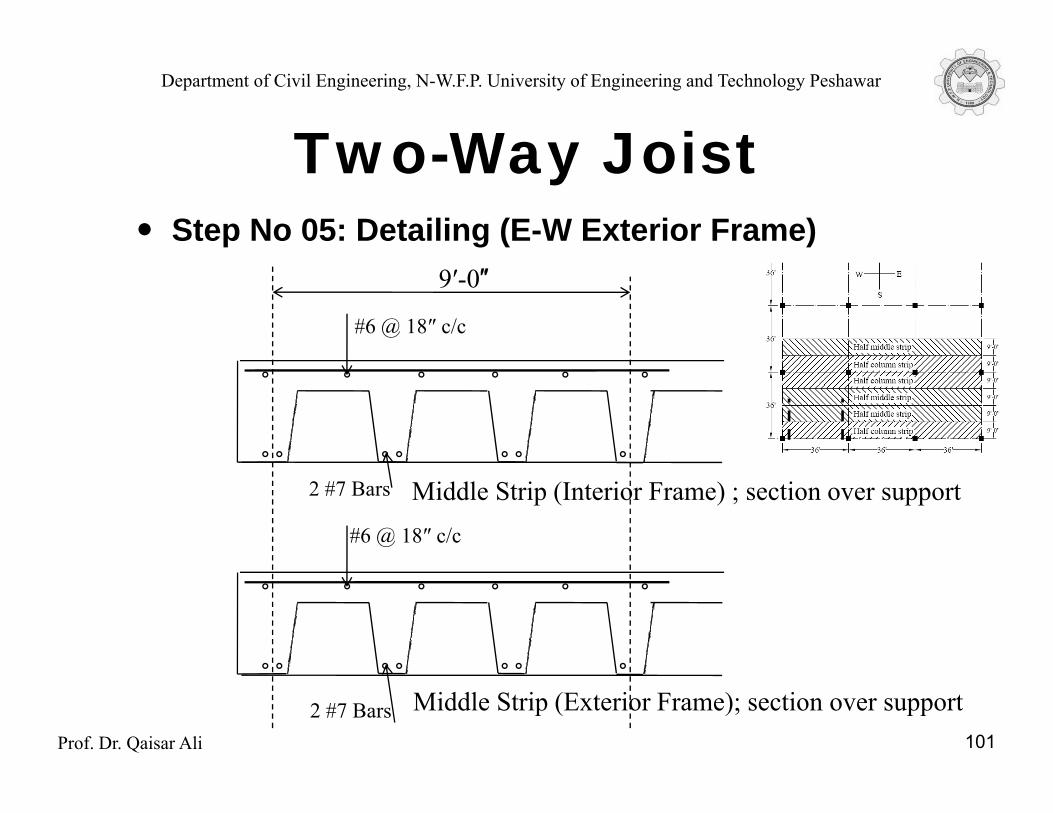
Two Way JoistStep No 05: Detailing (E-W Exterior Frame)
Two-Way Joist
#6 @ 18″ c/c
9′-0″
Middle Strip (Interior Frame) ; section over support2 #7 Bars
#6 @ 18″ c/c
Prof. Dr. Qaisar Ali 101
Middle Strip (Exterior Frame); section over support2 #7 Bars
Department of Civil Engineering, N-W.F.P. University of Engineering and Technology Peshawar
The End
Prof. Dr. Qaisar Ali 102