
LECTURE 10 - SPUR GEAR DESIGN
17
Machine Design II Prof. K.Gopinath & Prof. M.M.Mayuram Indian Institute of Technology Madras Module 2 - GEARS Lecture 10 - SPUR GEAR DESIGN Contents 10.1 Problem 3 Spur gear design 10.1.1 Buckingham Approach 10.1.2 AGMA Approach 10.1 Problem 3 - Design of Spur gear A pair of gears is to be designed to transmit 30kW power from a pinion running at 960rpm to a gear running at 320rpm. Design the gears so that they can last for 10 8 cycles. Assume 20 o full depth involute spur gear for the system. Motor shaft diameter is 30mm. Data given: W = 30 kW; n 1 = 960 rpm; n 2 = 320 rpm; Life = 10 8 cycles; 20 o full depth involute spur gear. Solution: i = n 1 / n 2 = 960 / 320 = 3 In order to keep the size small and meet the centre distance, Z 1 = 17 chosen Z 2 = i Z 1 = 3 x 17 = 51 n x x . rad / s 1 2 2 960 100 48 60 60 Torque is given by, 1 w 30x1000 T 298 100.48 .57 Nm
Transcript of LECTURE 10 - SPUR GEAR DESIGN

Machine Design II Prof. K.Gopinath & Prof. M.M.Mayuram
Indian Institute of Technology Madras
Module 2 - GEARS
Lecture 10 - SPUR GEAR DESIGN
Contents
10.1 Problem 3 Spur gear design
10.1.1 Buckingham Approach
10.1.2 AGMA Approach
10.1 Problem 3 - Design of Spur gear
A pair of gears is to be designed to transmit 30kW power from a pinion running at
960rpm to a gear running at 320rpm. Design the gears so that they can last for 108
cycles. Assume 20o full depth involute spur gear for the system. Motor shaft diameter is
30mm.
Data given:
W = 30 kW; n1= 960 rpm; n2 = 320 rpm; Life = 108 cycles; 20o full depth involute spur
gear.
Solution:
i = n1 / n2 = 960 / 320 = 3
In order to keep the size small and meet the centre distance, Z1 = 17 chosen
Z2 = i Z1 = 3 x 17 = 51
n x x
. rad/s
12 2 960100 48
60 60
Torque is given by,
1
w 30x1000T 298
100.48
.57 Nm

Machine Design II Prof. K.Gopinath & Prof. M.M.Mayuram
Indian Institute of Technology Madras
From Lewis equation for pinion we have,
t 1p p2
1
F 2T[ ]
bY m bYZ m (10.1)
SAE 1050 hardened by OQT with permissible bending strength of 532 and hardness of
223Bhn is selected for pinion and SAE 1045 hardened by WQT with permissible
bending strength of 487 and hardness of 215 Bhn is selected for the gear from Table
10.1. Face width b = 10m is chosen for both wheels.
Table 10.1 Safe static stresses for use in the Lewis equation
Material [σ ] MPa BHN
Gray cast iron ASTM 25 ASTM 35 ASTM 50 Cast steel(low carbon) 0.2% C not heat treated 0.2% C WQT Forged carbon steel SAE 1020 case hardened and WQT SAE 1030 not heat treated SAE 1035 not heat treated SAE 1040 not heat treated SAE 1045 hardened by WQT SAE 1045 hardened by WQT SAE 1050 hardened by OQT Alloy steel SAE 2320 case hardened and WQT SAE 2345 hardened by OQT SAE 3115 case hardened and OQT SAE 3145 hardened by OQT SAE 3245 hardened by OQT SAE 4340 hardened by OQT SAE 4640 hardened by OQT SAE 6145 hardened by OQT
122 183 228
304 380
274 304 350 380 456 487 532
761 761 563 806 989 989 837
1019
174 212 223
180 250
156 180 190 202 205 215 223
225 475 212 475 475 475 475 475

Machine Design II Prof. K.Gopinath & Prof. M.M.Mayuram
Indian Institute of Technology Madras
10.1.1 Buckingham approach:
The preliminary dimensions are found from Lewis equation and then they are checked
for dynamic loads by Buckingham equation.
From equation (10.1) substituting the value of b = 10m, we have,
(10.2) 1
p 31
p
T[ ] (
5YZ m
From Table 10.2, for the pinion Y = 0.25808 for Z1= 17
For the gear, Y = 0.39872, for Z2 = 51
For gear, Y[σ]g = 0.39872x 487 = 194.17
For pinion, Y[σ]p = 0.25808 x 542 = 139.87
Table 10.2 Values of the Lewis form factor Y
Number of teeth
Φ=20 a=0.8m* b=m
Φ=20 a=m b=1.25m
Φ=25 a=m b=1.25m
12 13 14 15 16 17 18 19 20 21 22 24 26 28 30 34 38 45 50 60 75 100
0.335 12 0.348 27 0.359 85 0.370 13 0.379 31 0.387 57 0.395 02 0.401 79 0.407 97 0.413 63 0.418 83 0.428 06 0.436 01 0.442 94 0.449 20 0.459 20 0.467 40 0.478 46 0.484 58 0.493 91 0.503 45 0.513 21
0.229 60 0.243 17 0.255 30 0.266 22 0.276 10 0.285 08 0.293 27 0.300 78 0.307 69 0.314 06 .0319 97 0.330 56 0.339 79 0.347 90 0.355 10 0.367 31 0.377 27 0.390 93 0.398 60 0.410 47 0.422 83 0.435 74
0.276 77 0.292 81 0.307 17 0.320 09 0.331 78 0.342 40 0.352 10 0.360 99 0.369 16 0.376 71 0.383 70 0.396 24 0.407 17 0.416 78 0.425 30 0.439 76 0.451 56 0.467 74 0.476 81 0.490 86 0.505 46 0.520 71

Machine Design II Prof. K.Gopinath & Prof. M.M.Mayuram
Indian Institute of Technology Madras
Hence, for the same face width pinion will be weaker and consideration for the design
is,
(10.3)
p 3 31
T 298.57 x1000 13610
5YZ m 5x0.25808x17m m
532MPa
3
m = 2.93 mm. Since motor shaft diameter is 30 mm, to get sufficiently large pinion m = 4
mm is taken.
Table 10.3 Data for pinion and gear
Wheel Z m b=10m d V =wrv Material Hardness
Pinion 17 4mm 40 mm 68mm 3.42 m/s SAE1050 223
Gear 51 4mm 40 mm 204mm 3.42 m/s SAE1045 215
We will now use Buckingham dynamic load approach for the design.
Ft = T1/r1 = 298.57/0.034 = 8781 N
Buckingham dynamic load is given by,
(10.4) ti
t
9.84V(Cb+F )F
9.84V +0.4696 Cb+F
For V=3.42 m/s permissible error is e= 0.088 mm from Fig.10.1. From Table 10.4, if we
choose I class commercial cut gears, expected error is 0.050 for m=4mm. In order to
keep the dynamic load low precision cut gears are chosen. So, e = 0.0125

Machine Design II Prof. K.Gopinath & Prof. M.M.Mayuram
Indian Institute of Technology Madras
Fig. 10.1 Permissible error
Table 10.4 Expected error in tooth profile Gear quality and expected error e
Module First class commercial gears
Carefully cut gears Precision gears
Up to 4 5 6 7 8 9 10
0.050 0.056 0.064 0.072 0.080 0.085 0.090
0.025 0.025 0.030 0.035 0.038 0.041 0.044
0.0125 0.0125 0.0150 0.0170 0.0190 0.0205 0.0220
Table 10.5 Value of C Tooth form Material of pinion and
gear C
14.5o
Cast iron and cast iron steel and cast iron steel and steel
5720 e 7850 e 11440 e
20o Full depth
Cast iron and cast iron steel and cast iron steel and steel
5930 e 8150 e 11860 e
20o Stub tooth
Cast iron and cast iron steel and cast iron steel and steel
6150 e 8450 e 12300 e
From Table 10.5, if material for both gear and pinion are steel, then,

Machine Design II Prof. K.Gopinath & Prof. M.M.Mayuram
Indian Institute of Technology Madras
C = 11860e = 11860 x 0.0125 = 148.25
Substituting the values Ft = 8781 N, C = 148 .25, V=3.42 m/s, b= 40mm in eqn. (10.4),
Buckingham dynamic load is given by,
(10.5)
(10.6)
6 for steel vs steel, pinion and gear Cp = 191 MPa0.5 and substituting i
3, Ф=200 we
Elastic coefficient Cp for spur gears in MPa0.5
M
i
9.84x3.42(148.25x40+8781)F 5464N
9.84x3.42+0.4696 148.25x40+8781
Fd = Ft + Fi = 8781 + 5464 = 14245 N
Beam strength of the pinion is given by,
Ftp = bYm [σ]p = 40x0.25808 x4x542 = 22381 N
Since Ftp(22381)> Fd(14245) the design is safe from tooth bending failure
consideration.
Wear strength of the pinion is given by,
2
[ ]
From Table 10.
Hts 1F bd I
C
p
=
o osin cos i sin 20 cos20 3I 0.1205
2 i 1 2 3 1
Table 10.6
Gear aterial Pinion Material
(µ=0.3 in all cases) Steel Cast iron Al Bronze Tin Bronze
Steel, E=207 GPa 191 166 162 158
Cast iron, E=131 GPa 166 149 149 145
Al Bronze, E=121 GPa 162 149 145 141
Tin Bronze,GPa
158 145 141 137 E=110

Machine Design II Prof. K.Gopinath & Prof. M.M.Mayuram
Indian Institute of Technology Madras
Surface fatigue strength of the pinion material is σsf = σsf’ KL KR KT
raph1
o
Pa) for metallic spur gears (107 cycle
life 99% reliability and temperature <120oC)
Material
σsf’ = 2.8(Bhn) – 69MPa
= 2.8 x 223-69 = 555.4MPa
KL= 0.9 for 108 cycles life from g
KR = 1.0 taken for 99 reliability
KT = 1.0 for operating temperature <120 C (assumed)
Table 10.7 Surface fatigue strength σsf’ (M
σsf’(MPa)
Steel 2.8 (Bhn)-69MPa
Nodular iron 0.95(2.8(Bhn)-69MPa)
Cast iron, grade 20 379
Cast iron, grade 30 482
Cast iron, grade 40 551
Tin Bronze, AGMA 2C (11% Sn) 207
Aluminium Bronze (ASTM 148 – 52) (Alloy 9C – H.T.) 448
Fig.10.2 Life factor KL

Machine Design II Prof. K.Gopinath & Prof. M.M.Mayuram
Indian Institute of Technology Madras
Table 10.8 Reliability factor KR
Reliability (%) KR
50 1.25
99 1.00
99.9 0.80
Surface fatigue strength of the pinion material is σsf = σsf’ KL KR KT
= 555.4x0.9x1x1 = 500MPa
a
ear strength of the pinion is:
ince Fts (1860) << Fd (14245), the design is not safe. Revision is necessary.
ing,
and increase the b to 13m = 13 x 4 = 52 mm.
w that,
ig.10.1
= 1261x0.9x1x1 = 1135MPa
Assuming, factor of safety, s = 1.1
[σH] = σsf /s = 500/1.1 = 455MP
W
2 2
Hts 1
p
[σ ] 455F = bd I = 40x68x0.1205 =1860 N
C 191
S
As the SAE1050 can attain a hardness of 800 VPN(~750 Bhn) after oil quench
increase the hardness to 475 Bhn
From Table 10.7, we kno
σsf’ = 2.8(Bhn) – 69MPa
= 2.8 x 475-69 = 1261MPa
KL= 0.9 for 108 cycles life from F
KR = 1.0 taken for 99 reliability
KT = 1.0 for operating temperature <120oC Assumed.
Surface fatigue strength of the pinion material is σsf = σsf’ KL KR KT

Machine Design II Prof. K.Gopinath & Prof. M.M.Mayuram
Indian Institute of Technology Madras
ntent on the hardness of fully hardened steel
H] = σsf /s = 1135 /1.1 = 1032MPa
Since Fts (12439)< Fd (14245), still it is not safe. Hence increase the module to 5mm.
Table 10.9 Properties of p d
Material Hardness
Fig.10.3 Effect of carbon co
Assuming factor of safety, s = 1.1
[σ2 2
Hts 1
pC 191
[σ ] 1032F = bd I =52x68x0.1205 =12439 N
inion an gear
Wheel Z m b=13m d V =wrv
Pinion 17 5mm 65 mm 85mm 4.27 m/s C 50 475
Gear 51 5mm 65 mm 255mm 4.27 m/s C 45 450

Machine Design II Prof. K.Gopinath & Prof. M.M.Mayuram
Indian Institute of Technology Madras
With new dimensions Fd = 16098 N
Fts = 19436 N. Since Fts > Fd, the revised design is safe from surface fatigue (pitting)
ts = 14951 N , Face width of 50 mm is adequate
Approach
0 kW; n1= 960 rpm; n2 = 320 rpm; Life = 108 cycles; 20o full depth involute spur
ear.
e of gears small and avoid interference, Z1 = 17 is chosen.
2 = i Z1 = 3 x 17 = 51
h bending stress is,
considerations.
If b = 50 mm, Fd = 13186 N
F
10.1.2 AGMA
Data given:
W = 3
g
Solution:
i = n1 / n2 = 960 / 320 = 3
In order to keep the siz
Z
11
2 n 2 x960= = 100.48rad / s
60 60
1
1 100.481000W 1000x30
T 298.57 Nm
AGMA equation for toot
d1 = m Z1
Face width, b= 10 to 13 m.
tv o mK KK
Fb m J
1v o m2
1b Z m JK K
2TK [ ]

Machine Design II Prof. K.Gopinath & Prof. M.M.Mayuram
Indian Institute of Technology Madras
b = 10 m is assumed for the first trial.
J = 0.34404 for pinion Z1= 17 mating with gear Z2=51
AGMA geometry factor J for teeth having Ø = 20o, a=1m, b=1.25m and
r
For gear J = 0.40808
These values are obtained from the table
Table 10.10
f =0.300m
Number of teeth in mating gear Numberof teeth
1 17 25 35 50 85 300 1000
18
19
20
21
22
24
26
28
30
34
38
45
50
60
75
100
150
300
Rack 0.305 75 0.465 54 0.484 15 0.499 88 0.534 67 0.534 67 0.552 72 0.571 73
0.244 86
0.247 94
0.250 72
0.253 23
0.255 52
0.259 51
0.262 89
0.265 80
0.268 31
0.272 47
0.275 75
0.280 13
0.282 52
0.286 13
0.289 79
0.293 13
0.297 38
0.301 41
0.324 04
0.330 29
0.336 00
0.341 24
0.346 07
0.354 68
0.362 11
0.368 60
0.374 62
0.383 94
0.391 70
0.402 23
0.408 08
0.417 02
0.426 20
0.435 61
0.445 30
0.455 26
0.332 12
0.338 78
0.344 85
0.350 44
0.355 59
0.364 77
0.372 72
0.379 67
0.385 80
0.396 71
0.404 46
0.415 79
0.422 08
0.431 73
0.441 63
0.451 80
0.462 26
0.473 04
0.338 40
0.345 37
0.351 76
0.357 64
0.363 06
0.372 75
0.381 15
0.388 51
0.395 00
0.405 94
0.414 80
0.426 85
0.435 55
0.443 83
0.454 40
0.465 27
0.476 45
0.487 98
0.344 04
0.351 34
0.358 04
0.364 22
0.369 92
0.380 12
0.388 97
0.396 73
0.403 59
0.415 17
0.424 56
0.437 35
0.444 48
0.455 40
0.466 68
0.478 27
0.490 23
0.502 78
0.350 50
0.358 22
0.365 32
0.371 86
0.377 92
0.388 77
0.398 21
0.406 50
0.413 83
0.426 24
0.436 33
0.450 10
0.457 78
0.469 60
0.481 79
0.494 37
0.507 36
0.520 78
0.355 94
0.364 05
0.371 51
0.378 41
0.384 79
0.396 26
0.406 25
0.415 04
0.422 83
0.436 04
0.446 80
0.461 52
0.469 75
0.482 43
0.495 54
0.509 09
0.523 12
0.537 65
0.361 12
0.369 63
0.377 49
0.384 75
0.391 48
0.403 60
0.414 18
0.423 51
0.431 79
0.445 86
0.457 35
0.473 10
0.481 93
0.495 57
0.509 70
0.524 35
0.539 54
0.555 33
The t iven by, ooth bending stress is g0.50.5
is assumed. v
78 (200V)K 1.15
78

Machine Design II Prof. K.Gopinath & Prof. M.M.Mayuram
Indian Institute of Technology Madras
Ko = 1.25 is taken assuming uniform power source and moderate shock load from the
table 7
Km = 1.3 assuming accurat for face width of about
50mm.
v
Driv chinery
e mounting and precision cut gears
Table 10.11 -O erload factor Ko
en Ma
Source of power U Moderate Shock Heavy Shock niform
Uniform 1.00 1.25 1.75
Light shock 1.25 1.50 2.00
Medium 2.25 shock 1.50 1.75
10.12 Load distribu cto
Face width ( mm)
Table tion fa r Km
Characteristics of Support 0 - 50 150 225 400 up
Accurate mountings, small bearing 1.3 1.4 1.5 1.8
clearances, minimum deflection, precision
gears
Less rigid mountings, less accurate gears,
contact across the full face
1.6
1.7
1.8
2.2
Accuracy and mounting such that less than Over
2.2
Over
2.2
Over
2.2
Over
2.2 full-face contact exists
Substituting these values in the equation,
1
1 v o m2 21
298570x1.15x1.25x1.3K K
10m x17xm x 0.34404
2TK
b Z m J
3m
9539

Machine Design II Prof. K.Gopinath & Prof. M.M.Mayuram
Indian Institute of Technology Madras
σe = σe’ kL kv ks kr kT kf km
The pinion is of steel C50 OQT with 223Bhn hardness and tensile strength of 660MPa
Bhn and tensile strength of 465MPa.
be <5mm; kS = 0.73 from the
ig.10.4 for σ
Fig. 10. 4 Surface factor ks
able Re ty r K
factor R
and the gear is of C45 OQT with hardness 210
For pinion σe’ = 0.5 σut = 0.5 x 660 = 330MPa
kL = 1 for bending, kV = 1 assumed expecting m to
F ut= 660MPa, kr = 0.897 for 90% reliability
T 10.13 liabili facto r
Reliability 0.50 0.90 0.95 0.99 0.999 0.9999
Factor Kr 1.000 0.897 0.868 0.814 0.753 0.702
kT =1 assumed based on operating temperature <120oC
kf = 1.- and km = 1.33 for σut= 660MPa ( Ultimate tensile strength = 660 MPa for
SAE 1050 con
σe
3 = 287.4MPa
umed
OQT dition)
= σe’ kL kv ks kr kT kf km
= 330x1x1x0.73x0.897x1x1x1.3
Factor of safety on bending of 1.5 ass

Machine Design II Prof. K.Gopinath & Prof. M.M.Mayuram
Indian Institute of Technology Madras
[σ] = σe
ous effects factor km
rom tooth bending fatigue considerations,
andard value. From this module, the dimensions
alculated are given in Table 10.14.
Tab 10 ens s o a
Material Hardness
/ s = 287.4 / 1.5 =191.6MPa
Fig.10.5 - Miscellane
F
1 3m
9539[ ] 191.6
Solving the equation we get m = 3.68mm
Now take m=4 mm as the next st
c
le .14 Dim ion f pinion nd gear
Wheel Z m b=10m d V =wrv
Pinion 17 4mm 40 mm 68mm 3.42 m/s C 50 223
Gear 51 4mm 40 mm 204mm 3.42 m/s C 45 205
Ft = T1 / r1 = 29857/34 = 8781N
The tooth has to be checked from surface durability considerations now.
he contact stress equation of AGMA is given below:
steel
T
t
H p V o m1bd I
FC K K K
Cp = 191 MPa0.5 from the table for steel vs

Machine Design II Prof. K.Gopinath & Prof. M.M.Mayuram
Indian Institute of Technology Madras
Substituting i =3, Ф=20 we get I= 0.1205 0
o = 1.25 and Km = 1.3 assumed as in the case of bending stress calculation
H = 1209MPa
strength of the pinion material is given by,
ph1
oC assumed.
lues in the equation,
get,
0/1.1 = 455MPa
o osin cos i sin 20 cos20 3
I 02 i 1 2 3 1
.1205
0.5 0.50.5 0.5
v
78 (200V) 78 (200x3.42)K 1
78 78
.15
From Table 10.11 and 10.12,
K
t
o m
F 8781x1.15x1.25x1.3K K 191H p V
1
C Kbd I 40x68x0.1205
σ
The surface fatigue
σsf = σsf’ KL KR KT
Where σsf’ = 2.8(Bhn) – 69MPa
= 2.8 x 223-69 = 555.4MPa
KL= 0.9 for 108 cycles life from gra
KR = 1.0 taken for 99% reliability
KT = 1.0 for operating temperature <120
Substituting the va
σsf = σsf’ KL KR KT
= 555.4x0.9x1x1 = 500MPa
Assuming a factor of safety, s = 1.1
From Fig. 10.2 and Table 10.8, we
[σH] = σsf /s = 50
σH = 1209MPa

Machine Design II Prof. K.Gopinath & Prof. M.M.Mayuram
Indian Institute of Technology Madras
Since σH (1209) >> [σH] (455), the design is not safe and surface fatigue failure will
hardness of the material to 475Bhn and also increase the b to 13m
,
sf = σsf’ KL KR KT
475-69 = 1261MPa
R = 1.0 taken for 99% reliability
<120oC Assumed.
ssuming a factor of safety s = 1.1
H] = σsf /s = 1135 /1.1 = 1032MPa
s σH (1185) > [σH] (1032) the design is not safe from surface durability considerations.
ence increase the module to 5mm and take b=10m
occur.
Solution:
Increase the surface
= 13 x 4 = 52 mm
From Fig. 3 we get
Surface fatigue strength of the pinion material as
σ
where σsf’ = 2.8(Bhn) – 69MPa = 2.8 x
KL= 0.9 for 108 cycles life from graph1
K
KT = 1.0 for operating temperature
Substituting these values we get,
σsf = σsf’ KL KR KT
= 1261x0.9x1x1 = 1135MPa
A
[σ
t
H p V o m1
K 191
F 8781x1.15x1.25x1.3C K K
bd I 52x68x0.1205
A
H
tH p V o m
1
F 7025x1.17x1.25x1.3C K K K 191
bd I 50x85x0.1205
Machine Design II Prof. K.Gopinath & Prof. M.M.Mayuram
Indian Institute of Technology Madras
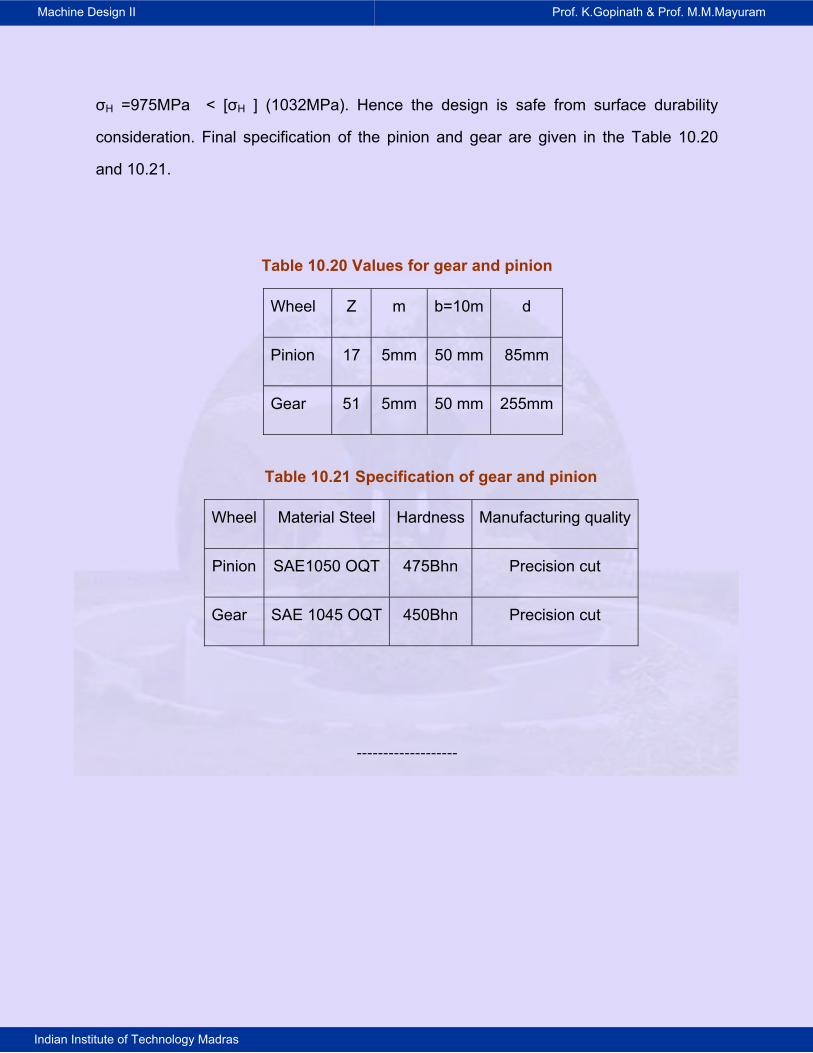
σH =975MPa < [σH ] (1032MPa). Hence the design is safe from surface durability
consideration. Final specification of the pinion and gear are given in the Table 10.20
and 10.21.
Table 10.20 Values for gear and pinion
Wheel Z m b=10m d
Pinion 17 5mm 50 mm 85mm
Gear 51 5mm 50 mm 255mm
Table 10.21 Specification of gear and pinion
Wheel Material Steel Hardness Manufacturing quality
Pinion SAE1050 OQT 475Bhn Precision cut
Gear SAE 1045 OQT 450Bhn Precision cut
-------------------