Lecture 1: Introduction to Magnets and Theoretical Fundamentals … · US Particle Accelerator...
51
Mauricio Lopes – FNAL Lecture 1: Introduction to Magnets and Theoretical Fundamentals
Transcript of Lecture 1: Introduction to Magnets and Theoretical Fundamentals … · US Particle Accelerator...

Mauricio Lopes – FNAL
Lecture 1: Introduction to Magnets and
Theoretical Fundamentals

2
Cartoon by Bruno Touschek (3 February 1921–25 May 1978)

A little bit of theory…
3
Lorentz Force:
𝑭 = 𝑞 𝑬 + 𝒗 × 𝑩
Magnetic rigidity:
𝐵𝑟 =𝐾2 + 2𝐾𝐸𝑜𝑞𝑐
𝑭 = 𝑞 𝒗 × 𝑩
F : force q : charge B : magnetic field
T : Beam energy c : speed of light Eo : Particle rest mass

… a little bit more
4
I
B
Biot-Savart law
𝑯.𝒅𝒍 = 𝐼
𝐵
𝜇𝑜2𝜋𝑟 = 𝐼
𝐵 =𝐼𝜇𝑜2𝜋𝑟
r
r : radius B : magnetic field mo : vacuum magnetic permeability

Units
5
SI units Variable Unit
F Newtons (N)
q Coulombs (C)
B Teslas (T)
I Amperes (A)
E Joules (J)
1 T = 10,000 G
𝜇𝑜 = 4π × 10−7𝑇.𝑚
𝐴
Charge of 1 electron ~ 1.6x10⁻¹⁹ C 1 eV = 1.6x10⁻¹⁹ J
(eV) for beams
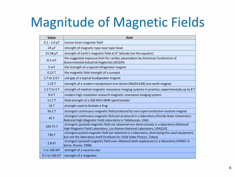
Magnitude of Magnetic Fields
6
Value Item
0.1 - 1.0 pT human brain magnetic field
24 µT strength of magnetic tape near tape head
31-58 µT strength of Earth's magnetic field at 0° latitude (on the equator)
0.5 mT the suggested exposure limit for cardiac pacemakers by American Conference of Governmental Industrial Hygienists (ACGIH)
5 mT the strength of a typical refrigerator magnet
0.15 T the magnetic field strength of a sunspot
1 T to 2.4 T coil gap of a typical loudspeaker magnet
1.25 T strength of a modern neodymium-iron-boron (Nd2Fe14B) rare earth magnet.
1.5 T to 3 T strength of medical magnetic resonance imaging systems in practice, experimentally up to 8 T
9.4 T modern high resolution research magnetic resonance imaging system
11.7 T field strength of a 500 MHz NMR spectrometer
16 T strength used to levitate a frog
36.2 T strongest continuous magnetic field produced by non-superconductive resistive magnet
45 T strongest continuous magnetic field yet produced in a laboratory (Florida State University's National High Magnetic Field Laboratory in Tallahassee, USA)
100.75 T strongest (pulsed) magnetic field yet obtained non-destructively in a laboratory (National High Magnetic Field Laboratory, Los Alamos National Laboratory, USA)[10]
730 T strongest pulsed magnetic field yet obtained in a laboratory, destroying the used equipment, but not the laboratory itself (Institute for Solid State Physics, Tokyo)
2.8 kT strongest (pulsed) magnetic field ever obtained (with explosives) in a laboratory (VNIIEF in Sarov, Russia, 1998)
1 to 100 MT strength of a neutron star
0.1 to 100 GT strength of a magnetar

Types of magnets
7
• Dipoles
• Quadrupoles
• Sextupoles
• Correctors
• Septa
• Kickers

Optics analogy 1
8
Prism Lens
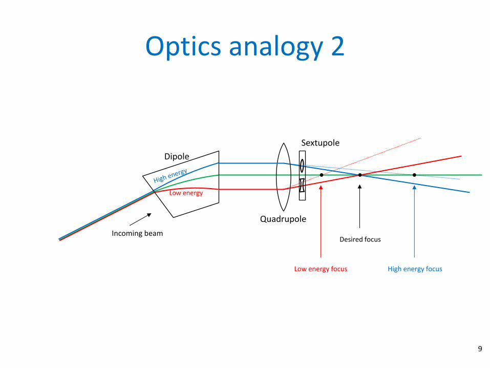
Optics analogy 2
9
Dipole
Quadrupole
Incoming beam
Low energy
Sextupole
Desired focus
Low energy focus High energy focus

Dipole
10
The dipole magnet has two poles, a constant field and steers a particle beam. USing the right hand rule, the positive dipole steer the rotating beam toward the left.

Dipoles
11
ALBA SR Combined Function Dipole

Quadrupole
12
The Quadrupole Magnet has four poles. The field varies linearly with the distance from the magnet center. It focuses the beam along one plane while defocusing the beam along the orthogonal plane. An F or focusing quadrupole focuses the particle beam along the horizontal plane.

Quadrupole
13
ALBA SR Quadrupole

Sextupole
14
The Sextupole Magnet has six poles. The field varies quadratically with the distance from the magnet center. It’s purpose is to affect the beam at the edges, much like an optical lens which corrects chromatic aberration. An F sextupole will steer the particle beam toward the center of the ring. Note that the sextupole also steers along the 60 and 120 degree lines.

Sextupole
ALBA SR Sextupole
15

Correctors
16
SPEAR3 Corrector

Current Carrying Septum
17

Eddy-Current Septum
18

Lambertson Septum
19

Kicker magnets
20

The forces on parallel currents is illustrated in the following figure. The force on a charge moving with a given velocity through a magnetic field is expressed with the lorentz force:
Magnetostriction
𝑭 = 𝑞 𝒗 × 𝑩
21

Magnetostriction
• Currents with the same charge travelling in the same direction attract.
• Currents with opposite charge travelling in the same direction repel.
• Currents with the same charge travelling in the opposite direction repel.
• Currents with the opposite charge travelling in the opposite direction attract.
22

Introduction to the Mathematical Formulation
• An understanding of magnets is not possible without understanding some of the mathematics underpinning the theory of magnetic fields. The development starts from Maxwell’s equation for the three-dimensional magnetic fields in the presence of steady currents both in vacuum and in permeable material.
• For vacuum and in the absence of current sources, the magnetic fields satisfy Laplace’s equation.
• In the presence of current sources (in vacuum and with permeable material) the magnetic fields satisfy Poisson’s equation. Although three dimensional fields are introduced, most of the discussion is limited to two dimensional fields. – This restriction is not as limiting as one might imagine since it can be shown
that the line integral of the three dimensional magnetic fields, when the domain of integration includes all regions where the fields are non-zero, satisfy the two dimensional differential equations.
23

Maxwell’s Equations (in vacuum)
𝛻. 𝑬 =𝜌
𝜀𝑜
𝛻.𝑩 = 0
𝛻 × 𝑬 = −𝜕𝑩
𝜕𝑡
𝛻 × 𝑩 = 𝜇𝑜𝑱 + 𝜇𝑜𝜀𝑜 𝜕𝑬
𝜕𝑡
Gauss’s law
Faraday’s law
Ampere’s law
𝑬.𝑑𝑨 =𝑄
𝜀𝑜
𝑩. 𝑑𝑨 = 0
𝑬. 𝑑𝒍 = − 𝜕𝑩
𝜕𝑡. 𝑑𝑨
𝑩. 𝑑𝒍 = 𝜇𝑜𝑰 + 𝜇𝑜𝜀𝑜 𝜕𝑬
𝜕𝑡. 𝑑𝑨
24

Maxwell’s Equations (in media)
𝛻.𝑫 = 𝜌𝑓
𝛻.𝑩 = 0
𝛻 × 𝑬 = −𝜕𝑩
𝜕𝑡
𝛻 × 𝑯 = 𝑱𝒇 + 𝜕𝑫
𝜕𝑡
Gauss’s law
Faraday’s law
Ampere’s law
𝑫.𝑑𝑨 = 𝑄𝑓
𝑩. 𝑑𝑨 = 0
𝑬. 𝑑𝒍 = − 𝜕𝑩
𝜕𝑡. 𝑑𝑨
𝑯. 𝑑𝒍 = 𝑰𝒇 + 𝜕𝑫
𝜕𝑡. 𝑑𝑨
US Particle Accelerator School – Grand Rapids, MI – June 2012 25

Maxwell’s Steady State Magnet Equations
𝛻.𝑩 = 0
𝛻 × 𝑩 = 𝜇𝑜𝑱
𝛻 × 𝑩 = 0
in the absence of sources
US Particle Accelerator School – Grand Rapids, MI – June 2012 26

The function of a complex variable
US Particle Accelerator School – Grand Rapids, MI – June 2012 27
𝑭 = 𝑨 + 𝑖𝑉
A : Vector potential V : Scalar potential
𝑩 = 𝜵 × 𝑨 =
𝒊 𝒋 𝒌
𝜕
𝜕𝑥
𝜕
𝜕𝑦
𝜕
𝜕𝑧𝐴𝑥 𝐴𝑦 𝐴𝑧
𝑩 = −𝜵𝑉 = − 𝒊𝜕𝑉
𝜕𝑥+ 𝒋𝜕𝑉
𝜕𝑦+ 𝒌𝜕𝑉
𝜕𝑧
𝜵 × 𝑩 = 𝜵 × 𝜵 × 𝑨 = 𝜵 𝜵. 𝑨 − 𝜵𝟐𝑨 = 0
0 (Coulomb gauge)
𝜵𝟐𝑨 = 0
A satisfies the Laplace equation!
𝜵. 𝑩 = 𝜵. −𝜵𝑉 = −𝜵𝟐𝑉 = 0 𝜵𝟐𝑉 = 𝟎
V also satisfies the Laplace equation!
The complex function 𝑭 = 𝑨 + 𝑖𝑉 must also satisfy the Laplace equation 𝜵𝟐𝑭 = 0

The Two-Dimensional Fields
US Particle Accelerator School – Grand Rapids, MI – June 2012 28
𝛻 × 𝑩 = 𝜇𝑜𝑱
𝒊 𝒋 𝒌𝜕
𝜕𝑥
𝜕
𝜕𝑦
𝜕
𝜕𝑧
𝐵𝑥 𝐵𝑦 𝐵𝑧
= 𝒊𝜕𝐵𝑧
𝜕𝑦−𝜕𝐵𝑦
𝜕𝑧+ 𝒋
𝜕𝐵𝑥
𝜕𝑧−𝜕𝐵𝑧
𝜕𝑥+ 𝒌
𝜕𝐵𝑦
𝜕𝑥−𝜕𝐵𝑥
𝜕𝑦
𝜕𝐵𝑦
𝜕𝑥−𝜕𝐵𝑥𝜕𝑦= 𝜇𝑜𝐽𝑧

Fields from the two-dimensional Function of a complex variable
US Particle Accelerator School – Grand Rapids, MI – June 2012 29
𝕫 = 𝑥 + 𝑖𝑦
𝑭 𝕫 = 𝑨 + 𝑖𝑉
𝐶𝑎𝑢𝑐ℎ𝑦 − 𝑅𝑖𝑒𝑚𝑎𝑛𝑛:
𝜕𝑨
𝜕𝑦= −𝜕𝑉
𝜕𝑥
𝜕𝑨
𝜕𝑥=𝜕𝑉
𝜕𝑦
𝑭′ 𝕫 =𝜕𝐹(𝕫)
𝜕𝕫=𝜕𝑨 + 𝑖𝜕𝑉
𝜕𝑥 + 𝑖𝜕𝑥
𝑭′ 𝕫 =
𝜕𝑨𝜕𝑥+ 𝑖𝜕𝑉𝜕𝑥
𝜕𝑥𝜕𝑥+ 𝑖𝜕𝑦𝜕𝑥
𝑭′ 𝕫 =
𝜕𝑨𝜕𝑦+ 𝑖𝜕𝑉𝜕𝑦
𝜕𝑥𝜕𝑦+ 𝑖𝜕𝑦𝜕𝑦
𝑩∗= 𝐵𝑥 − 𝑖𝐵𝑦 = 𝑖𝑭′ 𝕫
𝑩∗= 𝐵𝑥 − 𝑖𝐵𝑦 = 𝑖
𝜕𝑨
𝜕𝑥−𝜕𝑉
𝜕𝑥
𝑭′ 𝕫 =𝜕𝑨
𝜕𝑥+ 𝑖𝜕𝑉
𝜕𝑥 𝑭′ 𝕫 = −𝑖
𝜕𝑨
𝜕𝑦+𝜕𝑉
𝜕𝑦
𝑩∗= 𝐵𝑥 − 𝑖𝐵𝑦 =
𝜕𝑨
𝜕𝑦+ 𝑖𝜕𝑉
𝜕𝑦
𝐵𝑥 = −𝜕𝑉
𝜕𝑥
𝐵𝑥 =𝜕𝑨
𝜕𝑦
𝐵𝑦 = −𝜕𝑨
𝜕𝑥
𝐵𝑦 = −𝜕𝑉
𝜕𝑦

Solution to Laplace’s equation (2D)
US Particle Accelerator School – Grand Rapids, MI – June 2012 30
𝜵𝟐𝑭 =𝜕2𝐹
𝜕𝑥2+𝜕2𝐹
𝜕𝑦2= 0
𝜕𝐹
𝜕𝑥=𝑑𝐹
𝑑𝕫
𝜕𝕫
𝜕𝑥=𝑑𝐹
𝑑𝕫
𝜕2𝐹
𝜕𝑥2=𝜕
𝜕𝑥
𝑑𝐹
𝑑𝕫=𝑑2𝐹
𝑑𝕫2𝜕𝕫
𝜕𝑥=𝑑2𝐹
𝑑𝕫2
𝜕𝐹
𝜕𝑦=𝑑𝐹
𝑑𝕫
𝜕𝕫
𝜕𝑦=𝑑𝐹
𝑑𝕫𝑖
𝜕2𝐹
𝜕𝑦2=𝜕
𝜕𝑦
𝑑𝐹
𝑑𝕫𝑖 =𝑑2𝐹
𝑑𝕫2𝑖𝜕𝕫
𝜕𝑦= −𝑑2𝐹
𝑑𝕫2

Orthogonal Analog Model
31
The name of the method for picturing the field in a magnet is called the Orthogonal Analog
Model by Klaus Halbach. This concept is presented early in the lecture in order to
facilitate visualization of the magnetic field and to aid in the visualization of the vector and
scalar potentials.
• Flow Lines go from the + to - Coils. • Flux Lines are ortho-normal to the Flow Lines. • Iron Surfaces are impervious to Flow Lines.

Orthogonal Analog Model
32

Current Carrying Septum
33

Multipoles Expansion
34
𝕫 = 𝑥 + 𝑖𝑦
𝐹 𝕫 = 𝐴 + 𝑖𝑉 = 𝐶𝑛𝕫𝑛
∞
𝑛=1
where n is the order of the multipole
The ideal pole contour can be computed using the scalar equipotential. The field shape can be computed using the vector equipotential.

Example 1: Dipole (n=1)
35
𝐴 + 𝑖𝑉 = 𝐶1𝕫1 = 𝐶1(𝑥 + 𝑖𝑦)
𝑥 =𝐴
𝐶1
𝑦 =𝑉
𝐶1

Dipole (n=1)
36

Example 2: Quadrupole (n=2)
37
𝐴 + 𝑖𝑉 = 𝐶2𝕫2 = 𝐶2 𝑥 + 𝑖𝑦
2 = 𝐶2 𝑥2 − 𝑦2+ 𝑖2𝑥𝑦
𝑥2− 𝑦2 =𝐴
𝐶2
𝑥𝑦 =𝑉
2𝐶2

Quadrupole
38

• For the sextupole case, the function of a complex variable is written in polar form. – This case is presented to illustrate that both
polar and Cartesian coordinates can be used in the computation.
3sin3cos3
333
izC
ezCCzF i
3cos3
zCA
3sin3
zCV
Example 3: Sextupole (n=3)
𝕫 = 𝑥 + 𝑖𝑦 = 𝕫 𝑒−𝑖𝜃
39

sin3cos
sin
cos3cos
cos
3cos
3
1
3
1
3
1
C
Azy
C
Azx
C
Az
ntialVectorPote
ntialVectorPote
ntialVectorPote
sin3sin
sin
cos3sin
cos
3sin
3
1
3
1
3
1
C
Vzy
C
Vzx
C
Vz
ntialScalarPote
ntialScalarPote
tialSclarPoten
Scalar Potentials
Vector Potentials
US Particle Accelerator School – Grand Rapids, MI – June 2012 40

Sextupole Equipotentials
US Particle Accelerator School – Grand Rapids, MI – June 2012 41

Real and Skew Magnets
US Particle Accelerator School – Grand Rapids, MI – June 2012 42
• Magnets are described as real when the magnetic fields are vertical along the horizontal centerline :
Bx = 0 and By ≠ 0 for y=0
• Real magnets are characterized by C = real.
• Magnets are described as skew when the field are horizontal along the horizontal centerline:
Bx ≠ 0 and By = 0 for y=0
• Skew magnets are characterized by C = imaginary.

Dipole Example
US Particle Accelerator School – Grand Rapids, MI – June 2012 43
Real
Skew

Quadrupole Example
US Particle Accelerator School – Grand Rapids, MI – June 2012 44
Real
Skew

Ideal pole shapes
45
𝑥 =𝑨
𝐶1
𝐵𝑦 = −𝜕𝑨
𝜕𝑥 𝐵𝑦 = −
𝜕𝑉
𝜕𝑦
𝑦 = ℎ
Dipole
h = half gap
𝐵𝑦 = 𝐵𝑜
𝑉 = − 𝐵𝑜𝑑𝑦 = − 𝐵𝑜𝑦
𝑉 𝑥 = 0, 𝑦 = ℎ = −𝐵𝑜ℎ
−𝐵𝑜ℎ = −𝐵𝑜𝑦

Ideal pole shapes
US Particle Accelerator School – Grand Rapids, MI – June 2012 46
𝑥2− 𝑦2 =𝑨
𝐶2
Quadrupole
𝑦 =ℎ2
2𝑥 Hyperbola!
Sextupole
𝕫 = 𝑥2 + 𝑦2 =𝑨
𝐶3𝑐𝑜𝑠3𝜃
13
𝕫 = 𝑥2 + 𝑦2 =ℎ
𝑠𝑖𝑛3𝜃3
𝐵𝑦 = 𝐵′. 𝑥 @ 𝑦 = 0
𝐵𝑦 = 𝐵′′. 𝑥2 @ 𝑦 = 0
𝑉 = − (𝐵′. 𝑥)𝑑𝑦 = − 𝐵′. 𝑥𝑦 = −𝐵′. 𝑟2𝑐𝑜𝑠𝜃𝑠𝑖𝑛𝜃
𝑉 𝑟 = ℎ, 𝜃 = 𝜋/4 = −𝐵′ℎ2
2
−𝐵′ℎ2
2= −𝐵′𝑥𝑦
𝐵𝑦 = −𝜕𝑨
𝜕𝑥 𝐵𝑦 = −
𝜕𝑉
𝜕𝑦

• Using the concept of the magnetic potentials, the ideal pole contour can be determined for a desired field.
• Combined Magnet Example
– The desired gradient magnet field requires a field at a point and a linear gradient.
– Given:
A central field and gradient.
The magnet half gap, h, at the magnet axis.
– What is the ideal pole contour?
Complex Extrapolation
47

xBBBy '0 The desired field is;
The scalar potential satisfies the relation;
y
VBy
xyByBdyxBBV '' 00 Therefore;
hyx ,0, For on the pole surface,
hBhBhBVpole 00 0'
Therefore, the equation for the pole is, hBVxyByB pole 00 '
xBB
hBy
'0
0
or solving for y,
48
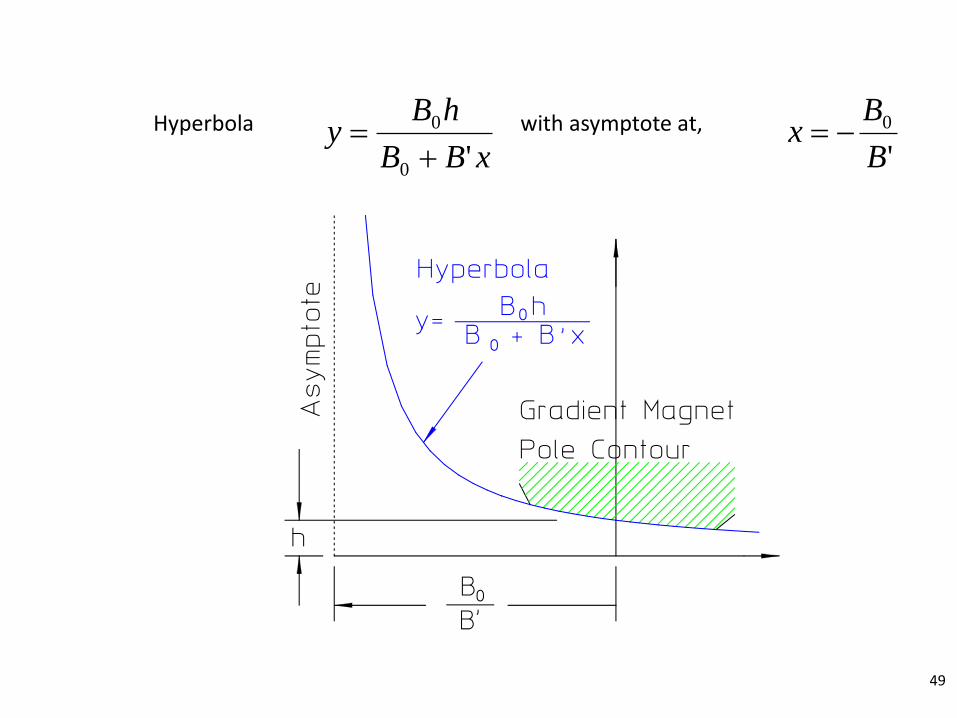
xBB
hBy
'0
0
'
0
B
Bx Hyperbola with asymptote at,
49

Section Summary
50
• We learned about the different kinds of magnets and their functions.
𝑭 𝕫 = 𝑨 + 𝑖𝑉 = 𝐶𝑛𝕫𝑛
∞
𝑛=1
• The ideal pole contour can be computed using the scalar equipotential.
• The field shape can be computed using the vector equipotential.
𝐵𝑥 = −𝜕𝑉
𝜕𝑥
𝐵𝑥 =𝜕𝑨
𝜕𝑦
𝐵𝑦 = −𝜕𝑨
𝜕𝑥
𝐵𝑦 = −𝜕𝑉
𝜕𝑦

Next…
51
• Multipoles
• Pole tip design
• Conformal mapping