Lecture 1: Introduction to Communication Systems Introduction.pdf · Title: Microsoft PowerPoint -...
17
1/28/2018 1 Lecture 1: Introduction to Communication Systems Dr. Mohammed Hawa Electrical Engineering Department The University of Jordan EE421: Communications I. Copyright © Dr. Mohammed Hawa Electrical Engineering Department, University of Jordan A Communication System • Purpose of a communication system: Carry information from one point to another. • A typical communication system consists of three main components: – Source – Channel – Destination 2
Transcript of Lecture 1: Introduction to Communication Systems Introduction.pdf · Title: Microsoft PowerPoint -...
1/28/2018
1
Lecture 1: Introduction to Communication Systems
Dr. Mohammed HawaElectrical Engineering Department
The University of Jordan
EE421: Communications I.
Copyright © Dr. Mohammed Hawa Electrical Engineering Department, University of Jordan
A Communication System
• Purpose of a communication system:Carry information from one point to another.
• A typical communication system consists of three main components:
– Source
– Channel
– Destination
2

1/28/2018
2
Copyright © Dr. Mohammed Hawa Electrical Engineering Department, University of Jordan
How to build it?
Three basic blocks:
Simple example:
m(t) = 5 V R 5 V
Channel: Copper Wires
3
Copyright © Dr. Mohammed Hawa Electrical Engineering Department, University of Jordan
Channel Impairments
4

1/28/2018
3
Copyright © Dr. Mohammed Hawa Electrical Engineering Department, University of Jordan
Channel Impairments
1. Attenuation: As the signal travels through thechannel it loses some of its energy (power) as heat inthe internal resistance of the channel. We say thesignal is attenuated.
5
Copyright © Dr. Mohammed Hawa Electrical Engineering Department, University of Jordan
Attenuation
• Attenuation can be problematic for long distance communications (say cross-country).
6

1/28/2018
4
Copyright © Dr. Mohammed Hawa Electrical Engineering Department, University of Jordan
Solutions to Attenuation(a) Use Amplifiers:
(c) Digital signals are less susceptible to attenuation (becauseof threshold detection at the receiver).
(b) Use channels with smaller attenuation levels (e.g., opticalfiber) – such channels are usually more expensive.
7
Copyright © Dr. Mohammed Hawa Electrical Engineering Department, University of Jordan
Fiber Cables for Long Distance
8
1/28/2018
5
Copyright © Dr. Mohammed Hawa Electrical Engineering Department, University of Jordan
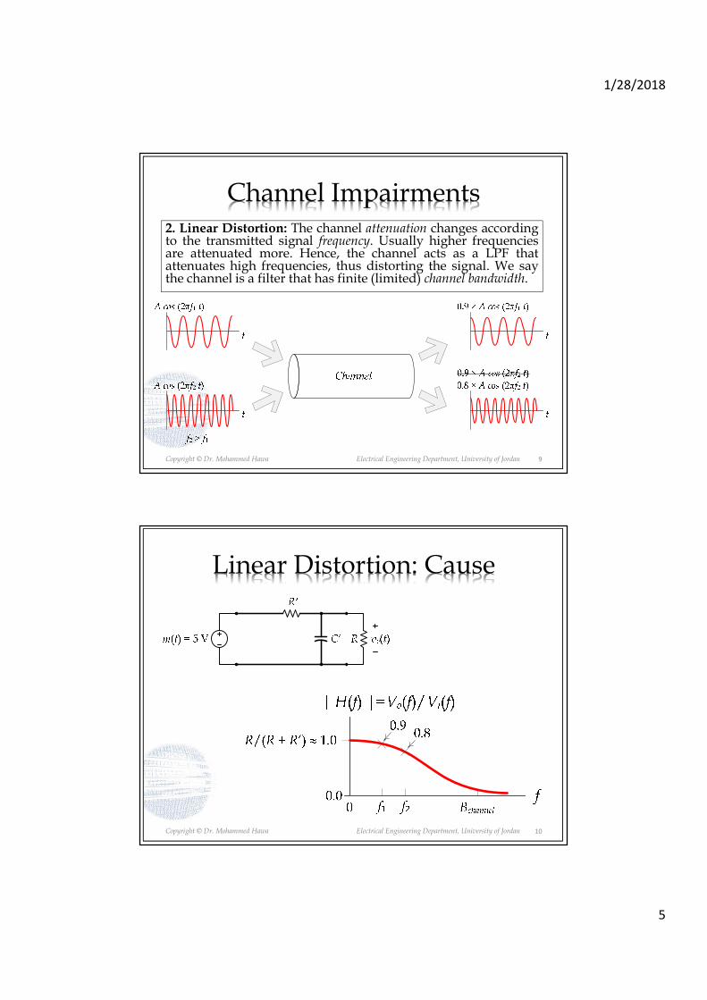
Channel Impairments2. Linear Distortion: The channel attenuation changes accordingto the transmitted signal frequency. Usually higher frequenciesare attenuated more. Hence, the channel acts as a LPF thatattenuates high frequencies, thus distorting the signal. We saythe channel is a filter that has finite (limited) channel bandwidth.
9
Copyright © Dr. Mohammed Hawa Electrical Engineering Department, University of Jordan
Linear Distortion: Cause
10

1/28/2018
6
Copyright © Dr. Mohammed Hawa Electrical Engineering Department, University of Jordan
Linear Distortion: Effects
t
t
t
m(t)
t
11
Copyright © Dr. Mohammed Hawa Electrical Engineering Department, University of Jordan
Linear Distortion: Effects
12

1/28/2018
7
Copyright © Dr. Mohammed Hawa Electrical Engineering Department, University of Jordan
Linearly-Distorted Signals
13
Copyright © Dr. Mohammed Hawa Electrical Engineering Department, University of Jordan
To Summarize:
• Channel Bandwidth Bchannel:– A property of the channel.– You read it from the data sheet of the channel.– The frequency after which the channel presents very
high attenuation.
• Signal Bandwidth Bm(t) = B:– A property of the signal.– You figure it out from the Fourier transform of the
signal.– The frequency above which m(t) has insignificant
(negligible) harmonics.
• Rule of thumb: signal bandwidth should be less than or equal to channel bandwidth.
14

1/28/2018
8
Copyright © Dr. Mohammed Hawa Electrical Engineering Department, University of Jordan
Solutions to Linear Distortion(a) The message should fit in the channel bandwidth(either send at smaller data rate or use a better channel)
(b) Use an Equalizerat the receiver
(c) Pre-distortion at the transmitter
15
Copyright © Dr. Mohammed Hawa Electrical Engineering Department, University of Jordan
Channel bandwidth depends on channel type and channel length
100
101
102
103
104
-60
-50
-40
-30
-20
-10
0
Signal Frequency (MHz)
Att
en
ua
tio
n (
dB
)
Attenuation for different cables and lengths
Coax 30 meter
Cat 5 30 meter
Coax 300 meter
Cat 5 300 meter
16

1/28/2018
9
Copyright © Dr. Mohammed Hawa Electrical Engineering Department, University of Jordan
Frequency Response (units of dB)
17
Copyright © Dr. Mohammed Hawa Electrical Engineering Department, University of Jordan
Channel Impairments
3. Non-Linear Distortion: The channel attenuation changesaccording to the transmitted signal amplitude and/or phase.Usually higher amplitudes are attenuated more. Thiscauses distortion to the signal.
18

1/28/2018
10
Copyright © Dr. Mohammed Hawa Electrical Engineering Department, University of Jordan
Fourier Transform Again!
19
Copyright © Dr. Mohammed Hawa Electrical Engineering Department, University of Jordan
Non-Linearly-Distorted Signals
20

1/28/2018
11
Copyright © Dr. Mohammed Hawa Electrical Engineering Department, University of Jordan
Distorted signals are not desired!
• Solutions to Non-Linear Distortion: Use an Equalizer at the receiver or Pre-distortion at the transmitter.
21
Copyright © Dr. Mohammed Hawa Electrical Engineering Department, University of Jordan
Channel Impairments
4. Noise: All the undesired signals (not part of theoriginal signal) that are added by the channel.Noise is a random (non-deterministic) signalgenerated by external and internal sources.
• External Sources: interference from signals transmitted on nearby channels (crosstalk), interference generated by contact switches, automobile ignition radiation, fluorescent lights, natural noise from lightning, solar radiation, etc.
22

1/28/2018
12
Copyright © Dr. Mohammed Hawa Electrical Engineering Department, University of Jordan
Example External Noise: Crosstalk
23
Copyright © Dr. Mohammed Hawa Electrical Engineering Department, University of Jordan
Noise
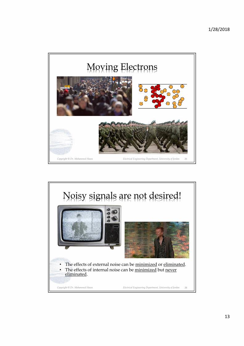
• Internal Sources: thermal noise (random motion of electrons in conductors, random diffusion and recombination of charged carriers in electronic devices).
24
1/28/2018
13
Copyright © Dr. Mohammed Hawa Electrical Engineering Department, University of Jordan
Moving Electrons
25
Copyright © Dr. Mohammed Hawa Electrical Engineering Department, University of Jordan
Noisy signals are not desired!
• The effects of external noise can be minimized or eliminated.• The effects of internal noise can be minimized but never
eliminated.
26

1/28/2018
14
Copyright © Dr. Mohammed Hawa Electrical Engineering Department, University of Jordan
Solutions for External Noise
27
a) Shielding or twisting.
b) A different cable design (coax, fiber, wave guide).
c) Proper design of the whole system.
d) Using filters at the receiver side: BPF, LPF, notch filter.
e) Digital transmission (threshold detection, orthogonality, FEC, etc.)
Copyright © Dr. Mohammed Hawa Electrical Engineering Department, University of Jordan
Solutions for Internal Noise
a) Cooling.
b) Using filters at the receiver side: BPF, LPF, notch filter.
c) Digital transmission (threshold detection, orthogonality, FEC, etc.)
28
1/28/2018
15
Copyright © Dr. Mohammed Hawa Electrical Engineering Department, University of Jordan
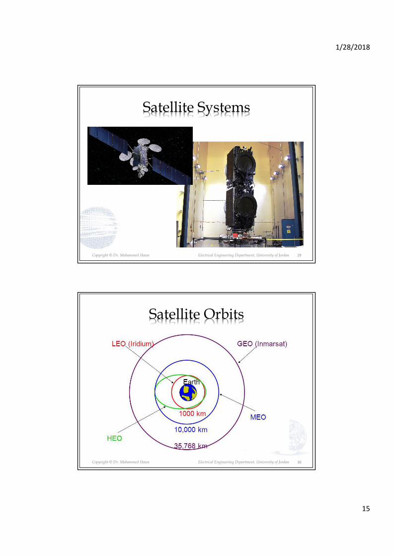
Satellite Systems
29
Copyright © Dr. Mohammed Hawa Electrical Engineering Department, University of Jordan 30
Satellite Orbits

1/28/2018
16
Copyright © Dr. Mohammed Hawa Electrical Engineering Department, University of Jordan
Impairments ALL Together
Attenuation + Noise:
We need new solutions: Regenrators (Digital Transmission)
31
Copyright © Dr. Mohammed Hawa Electrical Engineering Department, University of Jordan
Other Channel Impairments
5. Fading: Variable attenuation with time of day and receiver location (wireless systems).
6. Doppler Shift: Shift in the frequency of the transmitted signal. Shows up when we have a wireless channel and fast moving objects.
7. Frequency-reuse interference: Shows up in wireless systems when we re-use the same frequencies at multiple nearby locations to increase system capacity.
8. Chromatic Dispersion: Specific to optical fiber channels.
32
1/28/2018
17
Copyright © Dr. Mohammed Hawa Electrical Engineering Department, University of Jordan
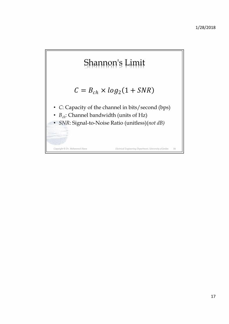
Shannon's Limit
• C: Capacity of the channel in bits/second (bps)
• Bch: Channel bandwidth (units of Hz)
• SNR: Signal-to-Noise Ratio (unitless)(not dB)
� = ��ℎ × ��2�1 + ����
33