Lecture 02(ch2 network models)
49
2.2 Computer Communication & Networks (CS372) Anwar Ghani Fall-2014 Department of Computer Science & Software Engineering International Islamic University, Islamabad
-
Upload
masood-karim -
Category
Documents
-
view
218 -
download
1
description
Â
Transcript of Lecture 02(ch2 network models)

2.2
Computer Communication & Networks (CS372)
Anwar Ghani Fall-2014
Department of Computer Science & Software Engineering International Islamic University, Islamabad

2.2
Chapter 2
Network Models
Copyright © The McGraw-Hill Companies, Inc. Permission required for reproduction or display.

2.3
2-1 LAYERED TASKS
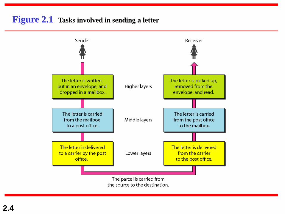
We use the concept of layers in our daily life. As an
example, let us consider two friends who communicate
through postal mail. The process of sending a letter to a
friend would be complex if there were no services
available from the post office.
Sender, Receiver, and Carrier
Hierarchy
Topics discussed in this section:
2.4
Figure 2.1 Tasks involved in sending a letter

2.5
Why layered approach?
1. To reduce complexity of communication task by
splitting it into several layered small tasks
2. Functionality of the layers can be changed as long as
the service provided to the layer above stays
unchanged
a) makes easier maintenance & updating
3. Each layer has its own task
4. Each layer has its own protocol

2.6
2-2 THE OSI MODEL
Established in 1947, the International Standards
Organization (ISO) is a multinational body dedicated to
worldwide agreement on international standards. An ISO
standard that covers all aspects of network
communications is the Open Systems Interconnection
(OSI) model. It was first introduced in the late 1970s.
Layered Architecture
Peer-to-Peer Processes
Encapsulation
Topics discussed in this section:
2.7
ISO is the organization.
OSI is the model.
Note

2.8
Figure 2.2 Seven layers of the OSI model
2.9
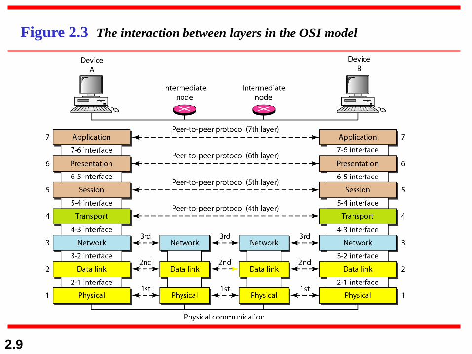
Figure 2.3 The interaction between layers in the OSI model
2.10
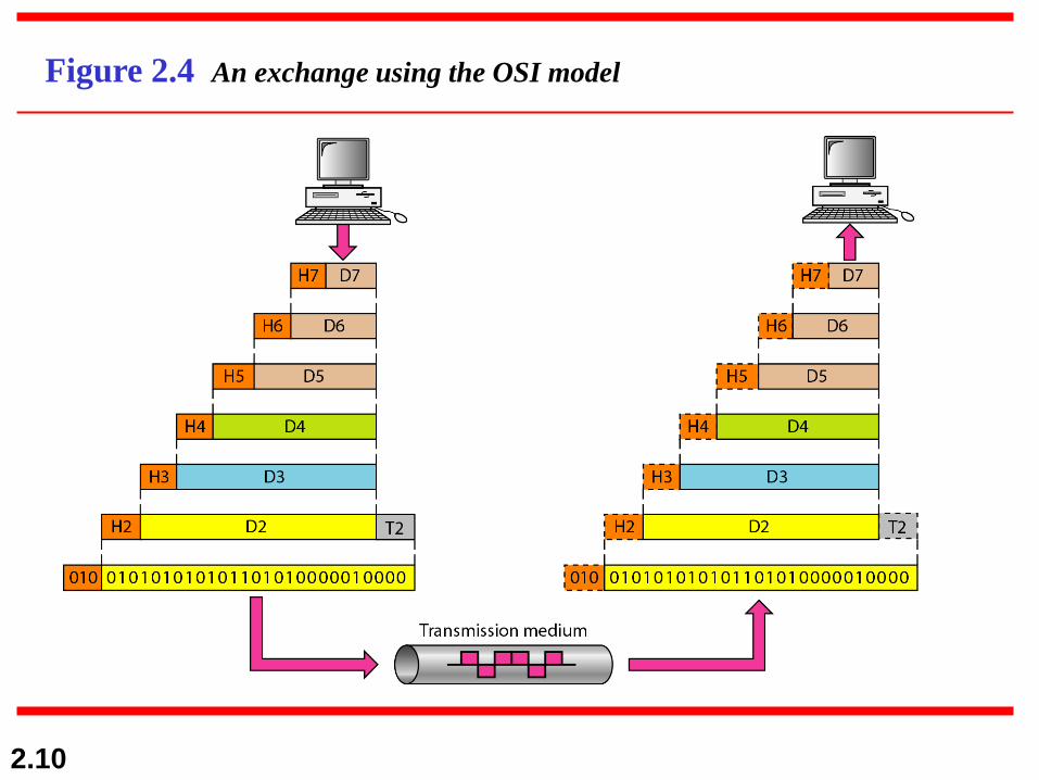
Figure 2.4 An exchange using the OSI model
2.11
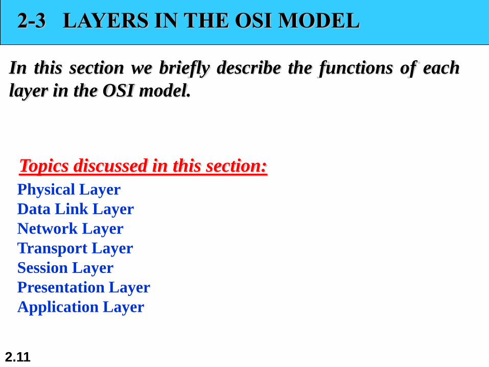
2-3 LAYERS IN THE OSI MODEL
In this section we briefly describe the functions of each
layer in the OSI model.
Physical Layer
Data Link Layer
Network Layer
Transport Layer
Session Layer
Presentation Layer
Application Layer
Topics discussed in this section:

2.12
Figure 2.5 Physical layer

2.13
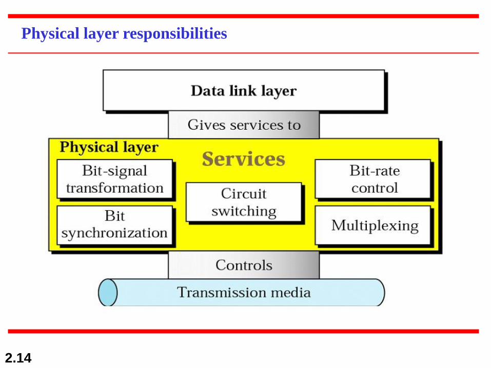
The physical layer is responsible for movements of
individual bits from one hop (node) to the next.
Note
2.14
Physical layer responsibilities

2.15
Figure 2.6 Data link layer

2.16
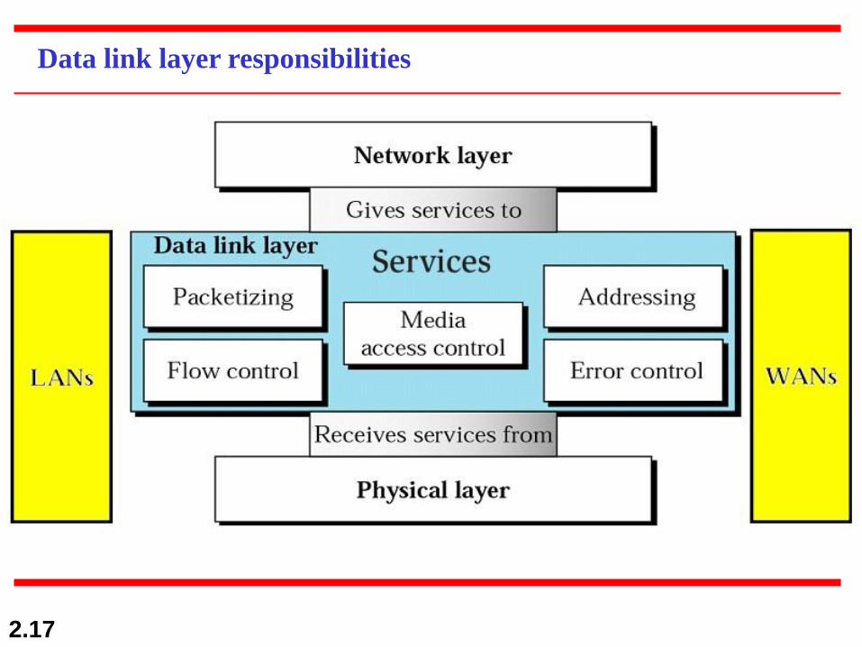
The data link layer is responsible for moving
frames from one hop (node) to the next.
Note
2.17
Data link layer responsibilities

2.18
Figure 2.7 Hop-to-hop delivery

2.19
Figure 2.8 Network layer

2.20
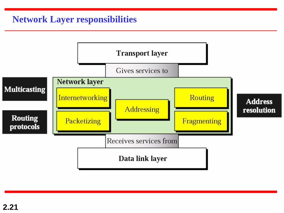
The network layer is responsible for the
delivery of individual packets from
the source host to the destination host.
Note
2.21
Network Layer responsibilities

2.22
Figure 2.9 Source-to-destination delivery

2.23
Figure 2.10 Transport layer

2.24
The transport layer is responsible for the delivery
of a message from one process to another.
Note

2.25
Transport Layer responsibilities

2.26
Figure 2.11 Reliable process-to-process delivery of a message
2.27
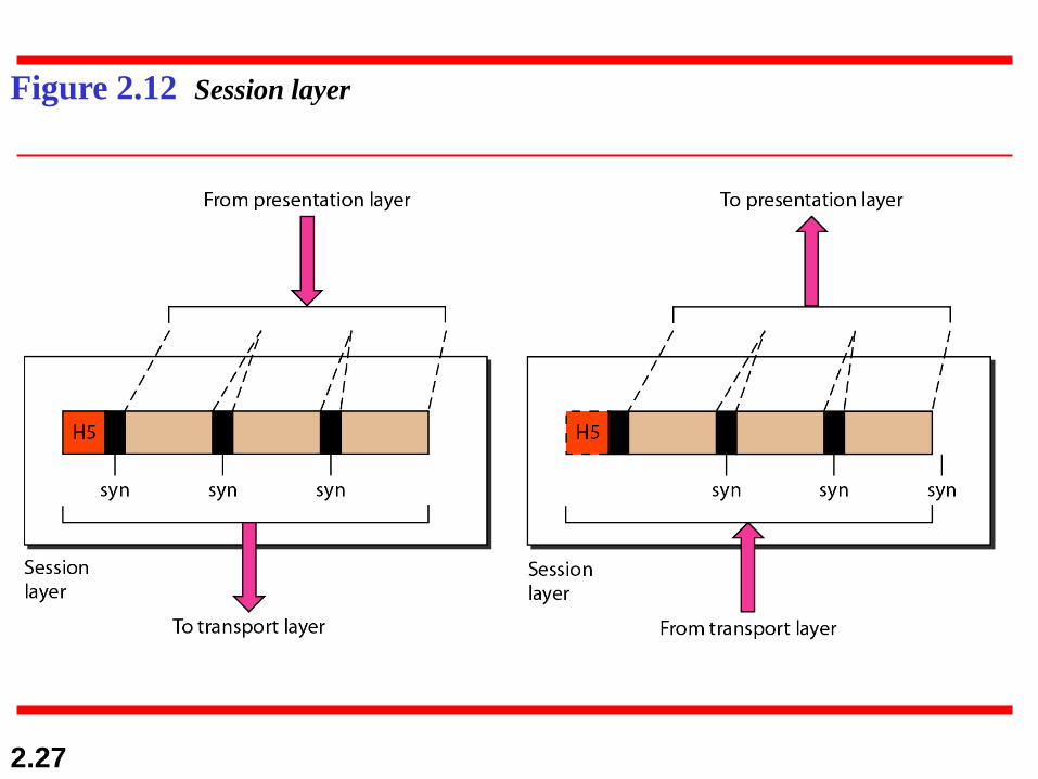
Figure 2.12 Session layer

2.28
The session layer is responsible for dialog
control and synchronization.
Note
2.29
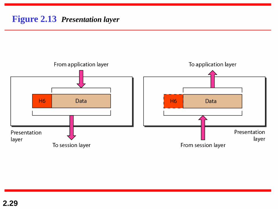
Figure 2.13 Presentation layer

2.30
The presentation layer is responsible for translation,
compression, and encryption.
Note
2.31
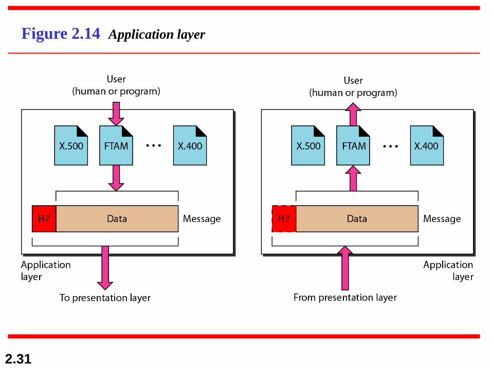
Figure 2.14 Application layer

2.32
The application layer is responsible for
providing services to the user.
Note

2.33
Application layer responsibilities
1. Network virtual terminal: user to log on to a remote host
2. File transfer, access, &management: access, retrieve,
manage or control files in a remote computer locally
3. Mail services: e-mail forwarding and storage
4. Directory services: provides distributed database sources
and access for global information

2.34
Figure 2.15 Summary of layers
2.35
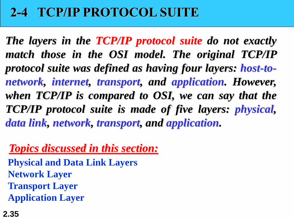
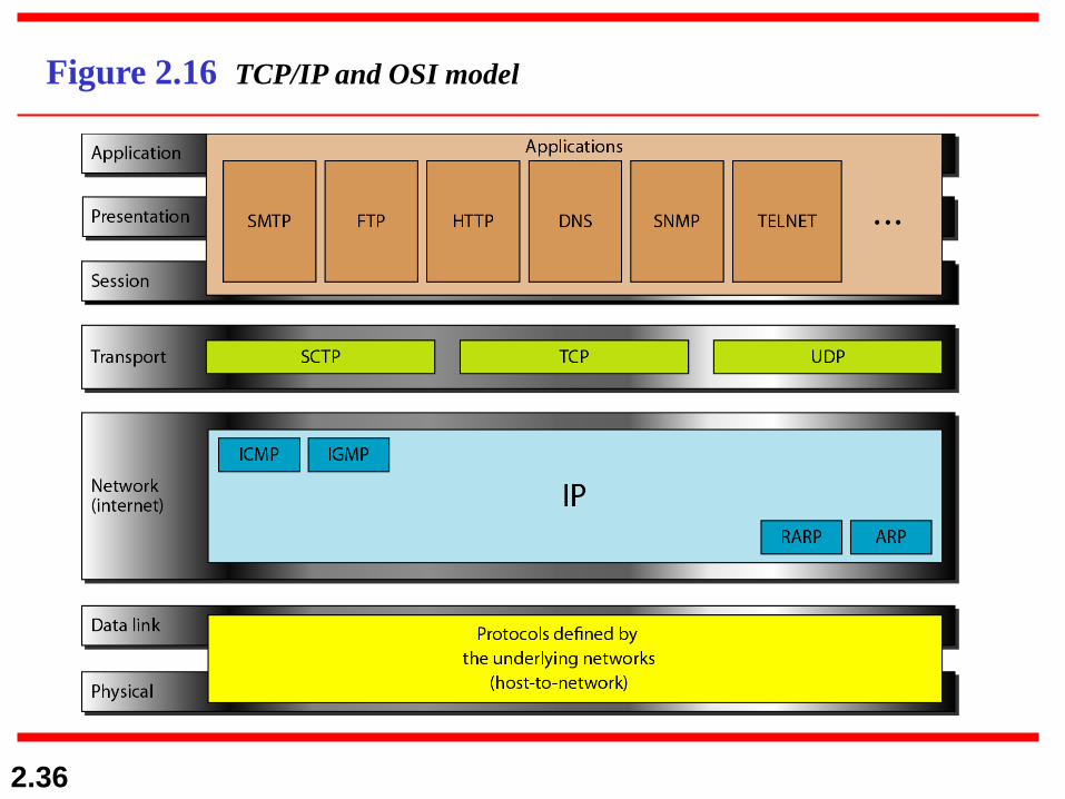
2-4 TCP/IP PROTOCOL SUITE
The layers in the TCP/IP protocol suite do not exactly
match those in the OSI model. The original TCP/IP
protocol suite was defined as having four layers: host-to-
network, internet, transport, and application. However,
when TCP/IP is compared to OSI, we can say that the
TCP/IP protocol suite is made of five layers: physical,
data link, network, transport, and application.
Physical and Data Link Layers
Network Layer
Transport Layer
Application Layer
Topics discussed in this section:
2.36
Figure 2.16 TCP/IP and OSI model
2.37
2-5 ADDRESSING
Four levels of addresses are used in an internet employing
the TCP/IP protocols: physical, logical, port, and specific.
Physical Addresses
Logical Addresses
Port Addresses
Specific Addresses
Topics discussed in this section:

2.38
Figure 2.17 Addresses in TCP/IP

2.39
Figure 2.18 Relationship of layers and addresses in TCP/IP

2.40
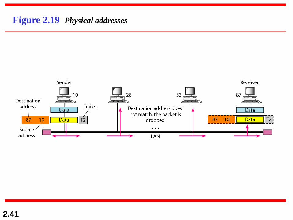
In Figure 2.19 a node with physical address 10 sends a
frame to a node with physical address 87. The two nodes
are connected by a link (bus topology LAN). As the
figure shows, the computer with physical address 10 is
the sender, and the computer with physical address 87 is
the receiver.
Example 2.1
2.41
Figure 2.19 Physical addresses

2.42
Most local-area networks use a 48-bit (6-byte) physical
address written as 12 hexadecimal digits; every byte (2
hexadecimal digits) is separated by a colon, as shown
below:
Example 2.2
07:01:02:01:2C:4B
A 6-byte (12 hexadecimal digits) physical address.
2.43
Figure 2.20 shows a part of an internet with two routers
connecting three LANs. Each device (computer or
router) has a pair of addresses (logical and physical) for
each connection. In this case, each computer is
connected to only one link and therefore has only one
pair of addresses. Each router, however, is connected to
three networks (only two are shown in the figure). So
each router has three pairs of addresses, one for each
connection.
Example 2.3

2.44
Figure 2.20 IP addresses
2.45
Figure 2.21 shows two computers communicating via the
Internet. The sending computer is running three
processes at this time with port addresses a, b, and c. The
receiving computer is running two processes at this time
with port addresses j and k. Process a in the sending
computer needs to communicate with process j in the
receiving computer. Note that although physical
addresses change from hop to hop, logical and port
addresses remain the same from the source to
destination.
Example 2.4

2.46
Figure 2.21 Port addresses

2.47
The physical addresses will change from hop to hop,
but the logical addresses usually remain the same.
Note

2.48
Example 2.5
A port address is a 16-bit address represented by one
decimal number as shown.
753
A 16-bit port address represented
as one single number.
For more information on port addresses
http://en.wikipedia.org/wiki/List_of_TCP_and_UDP_port_numbers
http://en.wikipedia.org/wiki/Port_(computer_networking)
1.49
QUESTIONS?