LEARNING GUIDE D-4 ANALYZE SINGLE-PHASE AC CIRCUITS · warnings and safety precautionary measures...
72
CONSTRUCTION ELECTRICIAN APPRENTICESHIP PROGRAM Level 4 Line D: Apply Circuit Concepts LEARNING GUIDE D-4 ANALYZE SINGLE-PHASE AC CIRCUITS D-4
Transcript of LEARNING GUIDE D-4 ANALYZE SINGLE-PHASE AC CIRCUITS · warnings and safety precautionary measures...

CONSTRUCTION ELECTRICIAN APPRENTICESHIP PROGRAMLevel 4 Line D: Apply Circuit Concepts
LEARNING GUIDE D-4ANALYZE SINGLE-PHASE AC CIRCUITS
D-4


ForewordThe Industry Training Authority (ITA) is pleased to release this major update of learning resources to support the delivery of the BC Electrician Apprenticeship Program. It was made possible by the dedicated efforts of the Electrical Articulation Committee of BC (EAC).
The EAC is a working group of electrical instructors from institutions across the province and is one of the key stakeholder groups that supports and strengthens industry training in BC. It was the driving force behind the update of the Electrician Apprenticeship Program Learning Guides, supplying the specialized expertise required to incorporate technological, procedural and industry-driven changes. The EAC plays an important role in the province’s post-secondary public institutions. As discipline specialists the committee’s members share information and engage in discussions of curriculum matters, particularly those affecting student mobility.
ITA would also like to acknowledge the Construction Industry Training Organization (CITO) which provides direction for improving industry training in the construction sector. CITO is responsible for organizing industry and instructor representatives within BC to consult and provide changes related to the BC Construction Electrician Training Program.
We are grateful to EAC for their contributions to the ongoing development of BC Construction Electrician Training Program Learning Guides (materials whose ownership and copyright are maintained by the Province of British Columbia through ITA).
Industry Training AuthorityJanuary 2011
DisclaimerThe materials in these Learning Guides are for use by students and instructional staff and have been compiled from sources believed to be reliable and to represent best current opinions on these subjects. These manuals are intended to serve as a starting point for good practices and may not specify all minimum legal standards. No warranty, guarantee or representation is made by the British Columbia Electrical Articulation Committee, the British Columbia Industry Training Authority or the Queen’s Printer of British Columbia as to the accuracy or sufficiency of the information contained in these publications. These manuals are intended to provide basic guidelines for electrical trade practices. Do not assume, therefore, that all necessary warnings and safety precautionary measures are contained in this module and that other or additional measures may not be required.

Acknowledgements and CopyrightCopyright © 2011 Industry Training Authority
All rights reserved. No part of this publication may be reproduced or transmitted in any form or by any means, electronic or digital, without written permission from Industry Training Authority (ITA). Reproducing passages from this publication by photographic, electrostatic, mechanical, or digital means without permission is an infringement of copyright law.
The issuing/publishing body is: Crown Publications, Queen’s Printer, Ministry of Citizens’ Services
The Industry Training Authority of British Columbia would like to acknowledge the Electrical Articulation Committee and Open School BC, the Ministry of Education, as well as the following individuals and organizations for their contributions in updating the Electrician Apprenticeship Program Learning Guides:
Electrical Articulation Committee (EAC) Curriculum SubcommitteePeter Poeschek (Thompson Rivers University)Ken Holland (Camosun College)Alain Lavoie (College of New Caledonia)Don Gillingham (North Island University)Jim Gamble (Okanagan College)John Todrick (University of the Fraser Valley) Ted Simmons (British Columbia Institute of Technology)
Members of the Curriculum Subcommittee have assumed roles as writers, reviewers, and subject matter experts throughout the development and revision of materials for the Electrician Apprenticeship Program.
Open School BCOpen School BC provided project management and design expertise in updating the Electrician Apprenticeship Program print materials:
Adrian Hill, Project ManagerEleanor Liddy, Director/SupervisorDennis Evans, Laurie Lozoway, Production Technician (print layout, graphics)Christine Ramkeesoon, Graphics Media CoordinatorKeith Learmonth, EditorMargaret Kernaghan, Graphic ArtistMax Licht, Graphic Artist
Publishing Services, Queen’s PrinterSherry Brown, Director of QP Publishing Services
Intellectual Property Program Ilona Ugro, Copyright Officer, Ministry of Citizens’ Services, Province of British Columbia
To order copies of any of the Electrician Apprenticeship Program Learning Guide, please contact us:
Crown Publications, Queen’s PrinterPO Box 9452 Stn Prov Govt563 Superior Street 2nd FlrVictoria, BC V8W 9V7Phone: 250-387-6409Toll Free: 1-800-663-6105Fax: 250-387-1120Email: [email protected]: www.crownpub.bc.ca
Version 1Corrected, September 2015 New, October 2012

CONSTRUCTION ELECTRICIAN APPRENTICESHIP PROGRAM: LEVEL 4 5
LEVEL 4, LEARNING GUIDE D-4:
ANALYZE SINGLE-PHASE AC CIRCUITSLearning Objectives . . . . . . . . . . . . . . . . . . . . . . . . . . . . . . . . . . . . . . . . . . . . . . . 7
Learning Task 1: Solve problems involving AC waveforms . . . . . . . . . . . . . . . . . . . . . . . 9Self-Test 1. . . . . . . . . . . . . . . . . . . . . . . . . . . . . . . . . . . . . . . . . 16
Learning Task 2: Solve problems involving AC circuits . . . . . . . . . . . . . . . . . . . . . . . . 21Self-Test 2. . . . . . . . . . . . . . . . . . . . . . . . . . . . . . . . . . . . . . . . . 49
Answer Key . . . . . . . . . . . . . . . . . . . . . . . . . . . . . . . . . . . . . . . . . . . . . . . . . . 63

6 CONSTRUCTION ELECTRICIAN APPRENTICESHIP PROGRAM: LEVEL 4

LEARNING ObjECTIVES D-4
CONSTRUCTION ELECTRICIAN APPRENTICESHIP PROGRAM: LEVEL 4 7
Learning Objectives• The learner will be able to apply AC circuit concepts.
Activities• Read and study the topics of Learning Guide D-4: Analyze Single-Phase AC Circuits.
• Complete Self-Tests 1 and 2. Check your answers with the Answer Key provided at the end of this Learning Guide.
Resources
You are encouraged to obtain the following texts to provide supplemental learning information:
• Alternating Current Fundamentals, John R. Duff and Stephen L. Herman, Delmar Publishers
• Canadian Electrical Code, Part 1, Current Edition, Canadian Standards Association

LEARNING ObjECTIVES D-4
8 CONSTRUCTION ELECTRICIAN APPRENTICESHIP PROGRAM: LEVEL 4
BC Trades Moduleswww.bctradesmodules.ca
We want your feedback! Please go the BC Trades Modules website to enter comments about specific section(s) that require correction or modification. All submissions will be reviewed and considered for inclusion in the next revision.
SAFETY ADVISORYBe advised that references to the Workers’ Compensation Board of British Columbia safety regulations contained within these materials do not/may not reflect the most recent Occupational Health and Safety Regulation. The current Standards and Regulation in BC can be obtained at the following website: http://www.worksafebc.com.
Please note that it is always the responsibility of any person using these materials to inform him/herself about the Occupational Health and Safety Regulation pertaining to his/her area of work.
Industry Training Authority January 2011

CONSTRUCTION ELECTRICIAN APPRENTICESHIP PROGRAM: LEVEL 4 9
Learning Task 1:
Solve problems involving AC waveformsYou already know that AC is continuously changing in both magnitude and direction. An alternating voltage (or current) rises from zero to a maximum positive value; then drops back to zero; and then repeats this action but in the opposite direction, or polarity. The shape of this AC waveform is referred to as a sine wave.
If you have any difficulty with the following information, review Learning Guide A-4: Solve Problems Using Applied Mathematics.
When an AC voltage is applied to a resistor, the current flow through the resistor will be a copy of the voltage waveform. As a result, the current is said to be in phase with the voltage.
True power or watts is produced whenever the voltage and current are in phase with each other. Although the voltage and current might be negative for a portion of time, the power waveform is still considered positive. See Figure 1.
AV
Figure 1—Voltage, current and power in a resistive AC circuit
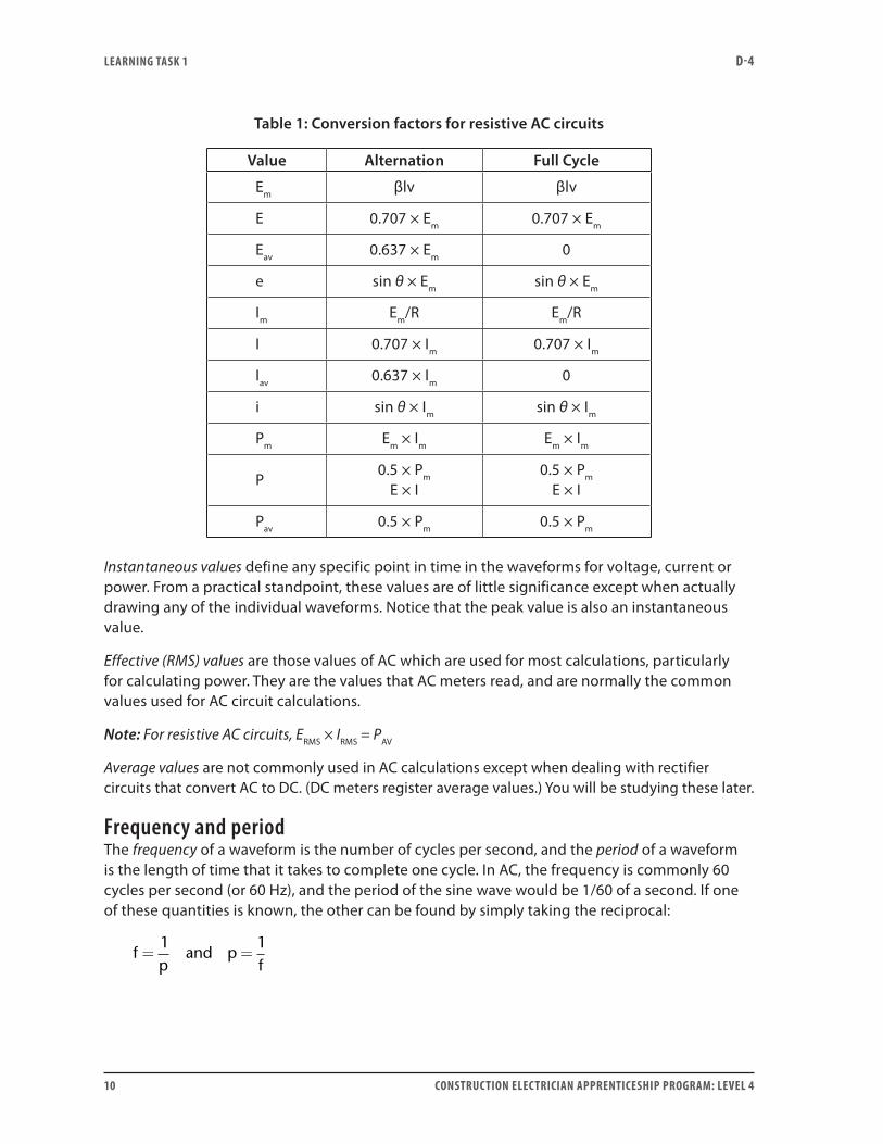
Since AC is continuously changing, there are several different values associated with AC waveforms. All of these values are commonly referenced to the peak (or maximum) value for conversion purposes. Table 1 shows the conversion factors for resistive AC circuits.
LEARNING TASk 1 D-4
10 CONSTRUCTION ELECTRICIAN APPRENTICESHIP PROGRAM: LEVEL 4
Table 1: Conversion factors for resistive AC circuits
Value Alternation Full Cycle
Em βlv βlv
E 0.707 × Em 0.707 × Em
Eav 0.637 × Em 0
e sin θ × Em sin θ × Em
Im Em/R Em/R
I 0.707 × Im 0.707 × Im
Iav 0.637 × Im 0
i sin θ × Im sin θ × Im
Pm Em × Im Em × Im
P0.5 × Pm
E × I0.5 × Pm
E × I
Pav 0.5 × Pm 0.5 × Pm
Instantaneous values define any specific point in time in the waveforms for voltage, current or power. From a practical standpoint, these values are of little significance except when actually drawing any of the individual waveforms. Notice that the peak value is also an instantaneous value.
Effective (RMS) values are those values of AC which are used for most calculations, particularly for calculating power. They are the values that AC meters read, and are normally the common values used for AC circuit calculations.
Note: For resistive AC circuits, ERMS × IRMS = PAV
Average values are not commonly used in AC calculations except when dealing with rectifier circuits that convert AC to DC. (DC meters register average values.) You will be studying these later.
Frequency and periodThe frequency of a waveform is the number of cycles per second, and the period of a waveform is the length of time that it takes to complete one cycle. In AC, the frequency is commonly 60 cycles per second (or 60 Hz), and the period of the sine wave would be 1/60 of a second. If one of these quantities is known, the other can be found by simply taking the reciprocal:
fp
and pf
= =1 1

LEARNING TASk 1 D-4
CONSTRUCTION ELECTRICIAN APPRENTICESHIP PROGRAM: LEVEL 4 11
where
f = frequency in cycles per second
p = period in seconds (or fractions of )
Out-of-phase waveformsIn certain AC applications, voltages and/or currents may be out of phase with each other; i.e., the waves do not reach their maximum and zero values at the same point in time. The time displacement between any two waveforms is called the phase angle. For purely resistive circuits, the phase angle is 0°. Figure 2 illustrates some common phase angles that you will encounter.
Figure 2—Out of phase waveforms
Figure 2(a) shows two sine waves that are out of phase by 90° (phase angle). Notice that Wave A is at a maximum positive value before Wave B reaches its maximum positive value. This means that Wave A leads Wave B by 90° (or Wave B lags Wave A by 90°).
Figure 2(b) also shows two sine waves with a phase displacement of 90°. Notice in this illustration that Wave B reaches its maximum positive value before Wave A. This means that Wave B leads Wave A by 90° (or Wave A lags Wave B by 90°).
Figure 2(c) illustrates two AC waves that are out of phase by 180°. Wave A reaches its maximum negative value at the same time that Phase B reaches its maximum positive value.
Figure 2(d) shows two AC waves that are out of phase by 120°. Notice that Wave A lags Wave B.

LEARNING TASk 1 D-4
12 CONSTRUCTION ELECTRICIAN APPRENTICESHIP PROGRAM: LEVEL 4
Other waveformsNot all AC waveforms are sinusoidal in shape. Two other types of waves that you will encounter are the square wave and the sawtooth wave. See Figure 3. These are found in certain electronic circuit applications.
Figure 3—Other waveforms
The lowest frequency component of a waveform is commonly referred to as the fundamental wave. In typical AC power distribution, the fundamental wave is a 60 Hz sine wave. Sometimes, higher frequency components called harmonics can be induced into the standard wave. Harmonics can be either odd or even in nature. For example, a 60 Hz wave could have a second (even) harmonic at 120 Hz and/or a third (odd) harmonic at 180 Hz that could distort the overall wave pattern. Figure 4 illustrates the effect of odd and even harmonics on a fundamental wave.
Figure 4—Effect of harmonics

LEARNING TASk 1 D-4
CONSTRUCTION ELECTRICIAN APPRENTICESHIP PROGRAM: LEVEL 4 13
Phasor representation of AC valuesThe graphical representation of AC values does not lend itself to easy mathematical analysis. Therefore, to simplify mathematical analysis of AC circuits, another method of representing these values is used. This method represents AC values with vectors or phasors.
• Scalars are quantities that possess magnitude only.
• Vectors are quantities that possess both magnitide and direction. Velocity is one vector quantity.
• Phasors are rotating vectors. They are used to represent quantities that vary with time. They possess both magnitude and angular velocity. This means that they have both speed and direction at any instant in time, but that the direction is constantly changing.
Sinusoidal waveforms of voltage and current are phasor quantities. The magnitude of these values vary with time. Figure 5 illustrates some different points in the sine wave.
Figure 5—Alternating current sine wave
Figure 6 illustrates the indicated points in the cycle of Figure 5 using phasors. The angular displacement (angle between the phasor and the 0° reference) indicates where the phasor is in the sinusoidal cycle.
Figure 6—Phasor representation of different sine wave points

LEARNING TASk 1 D-4
14 CONSTRUCTION ELECTRICIAN APPRENTICESHIP PROGRAM: LEVEL 4
Conventions used with phasors• The length of the phasor is most often used to represent the effective value of the sine
wave, but at times it is used to represent the peak value of the sine wave. Notice in Figure 6 that the length of the phasor does not change.
• Phasor algebra is done in the same way as vector algebra.
• The positive direction of phasor rotation is counterclockwise (CCW) from the zero degree reference (at 3 o’clock).
• When two phasors are shown on the same diagram, the phasor that is farthest CCW is said to lead the second phasor. That means it is farther into its cycle.
• The phasor farthest clockwise (CW) is said to lag the other phasor. That means it is not as far into its cycle as the other phasor.
• Waveforms represented by phasors on one phasor diagram must be sinusoidal and have the same frequency. This means that when two sine waves of the same frequency are added, the result is always a third wave of the same frequency.
• To draw phasors, they must be frozen in time. Normally, one of the phasors is picked as a reference phasor and is drawn on the reference at 0° (or 3 o’clock).
• If two similar sinusoidal waveforms are drawn on the same phasor diagram (i.e., two voltage waveforms, or two current waveforms), they must be drawn to the same scale. The same is true for power waveforms. However, if two dissimilar sinusoidal waveforms are drawn on the same diagram (i.e., voltage and current), their scales may differ.
• Current phasors are normally shown with closed arrowheads, and voltages are normally shown with open arrowheads.
Subscript notationVoltage phasors are generally shown with subscript notation. A good understanding of the conventions of subscript notation is critical to the understanding of AC circuit analysis.
In a DC circuit, it is easy to show the relative polarities between two points simply by placing (+) or (–) signs in the circuit. In AC circuits, the relative polarities are constantly changing, so a new convention must be adapted. This convention is called double subscript notation.
A voltage phasor is normally labelled E with two subscripts. The order of the subscripts is very important. If you mix them up, you will end up with two wrong answers.

LEARNING TASk 1 D-4
CONSTRUCTION ELECTRICIAN APPRENTICESHIP PROGRAM: LEVEL 4 15
Figure 7—Use of subscript notation
The two subscripts indicate the two points between which the voltage exists. For example, the label EAB can be referred to as the voltage at A with respect to B. Notice in Figure 7(a), the voltage EAB = +1.5 V and EBA = –1.5 V. In Figure 7(b), the voltage EAB = –1.5 V and EBA = +1.5 V.
Phasor representation of a purely resistive AC circuitIn a purely resistive AC circuit, the voltage and current are in phase. Previously, Figure 1 showed a graphical representation of the voltage and current waveforms. Figure 8 shows a phasor representation of the same voltage and current in a purely resistive circuit. The voltage phasor is drawn with the open arrowhead; the current phasor is drawn right over top of it with the closed arrowhead. The fact that both phasors point in the same direction indicates that they are in phase.
Figure 8—Phasor representation of voltage and current in a purely resistive circuit
Now do Self-Test 1 and check your answers.

LEARNING TASk 1 D-4
16 CONSTRUCTION ELECTRICIAN APPRENTICESHIP PROGRAM: LEVEL 4
Self-Test 1Questions 1 to 5 refer to Figure 1.
Figure 1—Diagram for Questions 1 to 5
1. As illustrated in Figure 1, when the voltage and current curves reach their maximum positive
value at the same instant in time, they are said to be .
2. How is the power curve plotted when using the voltage and current curves?
3. Is the power curve a sinusoidal curve? If not, how would you describe it?

LEARNING TASk 1 D-4
CONSTRUCTION ELECTRICIAN APPRENTICESHIP PROGRAM: LEVEL 4 17
4. How is it that the power curve has a positive value when the current and voltage are both negative?
5. The power curve is constantly changing in value, just like the voltage and current curves. When referring to power in an AC circuit, what value of power do we mean?
6. Besides the sine wave, what are two other types of AC waveforms?
7. What is the mathematical relationship between frequency and period for a waveform?
8. What value of current and voltage do:
a. AC meters read
b. DC meters read
9. A sine wave current has an instantaneous maximum value of 150 A. What is the:
a. effective value of this current
b. average value of this current
10. What is the voltage rating required for the dielectric of a capacitor in order for it to withstand the peak voltage when used in a 120 V AC circuit?
11. A 240 V AC circuit supplies a 20 kW resistance furnace. What is the instantaneous peak value of current that would flow to this AC load?
LEARNING TASk 1 D-4
18 CONSTRUCTION ELECTRICIAN APPRENTICESHIP PROGRAM: LEVEL 4
12. A 10 Ω resistor connected to an AC supply conducts an instantaneous maximum current of 10 A. What is the average power produced?
13. A sine wave voltage has a peak value of 147 volts. What is the instantaneous value of voltage at 150° of the waveform?
14. For a 120 V AC supply, at what angle would the sine wave reach a value that is 50% of its peak value?
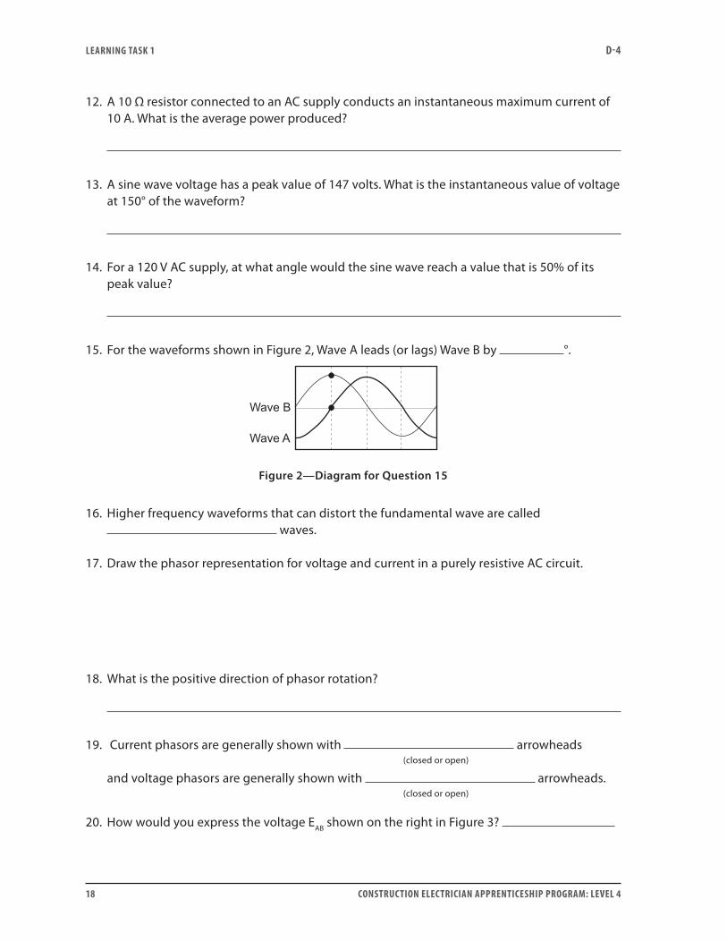
15. For the waveforms shown in Figure 2, Wave A leads (or lags) Wave B by °.
Figure 2—Diagram for Question 15
16. Higher frequency waveforms that can distort the fundamental wave are called waves.
17. Draw the phasor representation for voltage and current in a purely resistive AC circuit.
18. What is the positive direction of phasor rotation?
19. Current phasors are generally shown with arrowheads (closed or open) and voltage phasors are generally shown with arrowheads. (closed or open)
20. How would you express the voltage EAB shown on the right in Figure 3?

LEARNING TASk 1 D-4
CONSTRUCTION ELECTRICIAN APPRENTICESHIP PROGRAM: LEVEL 4 19
Figure 3—Diagram for Question 20
Go to the Answer Key at the end of the Learning Guide to check your answers.

20 CONSTRUCTION ELECTRICIAN APPRENTICESHIP PROGRAM: LEVEL 4

CONSTRUCTION ELECTRICIAN APPRENTICESHIP PROGRAM: LEVEL 4 21
Learning Task 2:
Solve problems involving AC circuitsResistive loads are characterized by the fact that:
• They produce heat.
• The voltage and current are in phase with each other.
• True power or watts occurs only in resistance.
When calculating the resistance in AC circuits, it is sometimes not as simple as applying Ohm’s law like in DC circuits. In AC there may be other factors to consider—like the presence of inductance and capacitance. The preferred method for solving for the value of the resistance component in AC is to apply Watt’s law, whereby:
RPI
or REP
= =2
2
If it is known that the circuit contains resistance only, then of course, Ohm’s law can also be used, whereby:
REI
=
When measuring resistance with an ohmmeter, remember that this measurement indicates the value of the DC ohmic resistance, and not the value of effective AC resistance.
Meter loading effect If you have any difficulty with the following information, you should review Level 1, Learning Guide E-1: Use Analogue Meters.
Whenever a voltmeter is used to measure the voltage drop across a circuit component, the meter is connected in parallel with that component. Since the voltmeter has an internal resistance (typically very high), the measured voltage across the component can be less than the true voltage drop. (This is because the equivalent resistance of the voltmeter and the circuit component is lower than that of the component alone.) This is of significance when measuring voltages across high-resistance loads.

LEARNING TASk 2 D-4
22 CONSTRUCTION ELECTRICIAN APPRENTICESHIP PROGRAM: LEVEL 4
k
kk
k
k k k
k
Figure 1—Voltmeter loading effect
Figure 1 shows a simple series circuit for electronics. Neglecting the voltmeter, the voltage drop across resistor R2 calculates to 7.5 V. Now, a voltmeter set on the 0–10 V range and having a sensitivity of 20 kΩ/V is connected to measure the voltage drop across R2. This changes the equivalent load resistance to 40 kΩ, which results in a voltage drop across the voltmeter of 6.3 V; this is 1.2 V less than the true voltage across R2.
Quite often, AC voltmeters have a lower sensitivity than DC voltmeters. To minimize the loading effect (as demonstrated in Figure 1), it is necessary to use a voltmeter with a higher sensitivity (Ω per V rating), such as a digital voltmeter.
Series, parallel and combination circuitsWhen working with applications of resistance in AC, the same fundamental relationships that you used in DC for series, parallel and combination circuits apply.
If you have any difficulty with the following information, you should review Level 1, Learning Guide D-2: Analyze DC Circuits.
For series circuits: The current is the same through all components, the total circuit voltage is greater than any individual voltage drop, and the total ohms opposition is greater than any individual value. These relationships are illustrated in Figure 2.
E
Figure 2—Series circuit

LEARNING TASk 2 D-4
CONSTRUCTION ELECTRICIAN APPRENTICESHIP PROGRAM: LEVEL 4 23
For parallel circuits: The voltage is the same across all components, the total current is greater than any of the branch currents, and the total ohms opposition is less than any individual branch value. These relationships are illustrated in Figure 3.
E
Figure 3—Parallel circuit
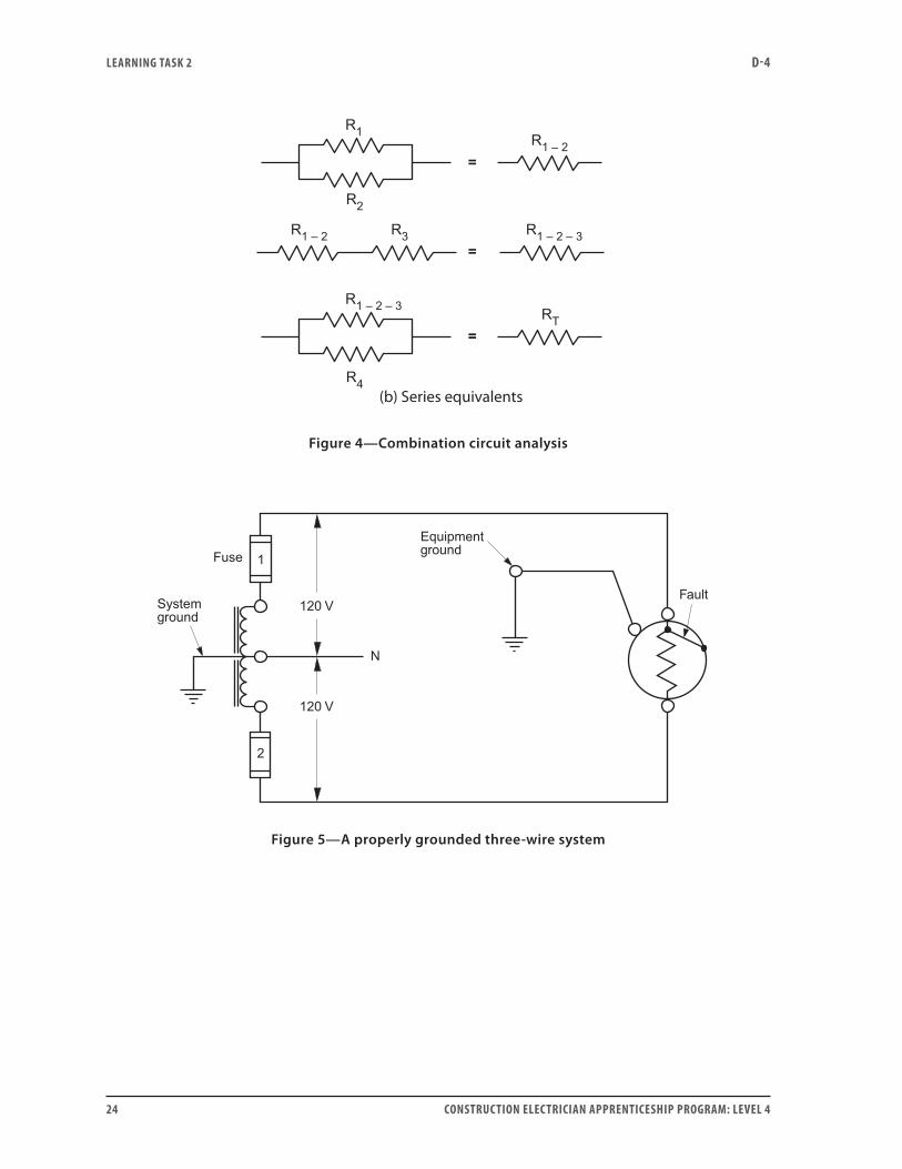
For combination (series-parallel) circuits: The individual relationships for both series and parallel circuits are applied. Generally, complicated combination circuits are broken down to a basic series-equivalent value, as illustrated in Figure 4.
Single-phase, three-wire AC circuitsThe single-phase, three-wire service is one of the most common methods of power distribution used for residential and commercial installations. This system offers two different voltages and uses less copper compared to an equivalent two-wire system.
I f you have any difficulty with the following information, you should review Level 1, Learning Guide D-2: Analyze DC Circuits.
As illustrated in Figure 5, a three-wire system must be properly grounded for safety reasons. It is important that the neutral is properly grounded to limit the circuit voltage-to-ground. Equally as important, the metallic parts of all electrical equipment must be properly bonded to ground to facilitate the operation of circuit protection devices in the event of a ground fault.
(a) Combination circuit
E
LEARNING TASk 2 D-4
24 CONSTRUCTION ELECTRICIAN APPRENTICESHIP PROGRAM: LEVEL 4
(b) Series equivalents
Figure 4—Combination circuit analysis
Figure 5—A properly grounded three-wire system

LEARNING TASk 2 D-4
CONSTRUCTION ELECTRICIAN APPRENTICESHIP PROGRAM: LEVEL 4 25
Figure 6—Balanced three-wire circuit
When connecting loads to a three-wire system, it is important to try to equally distribute the line-to-neutral loads to create a balanced load situation, as shown in Figure 6. This would reduce the current in the neutral conductor to a minimum value (ideally zero) to reduce line drop. Also, if an open neutral situation ever occurred, the voltages across the line-to-neutral loads would not be drastically altered from their normal values.
Note: A high resistance neutral situation has an effect similar to that of an open neutral condition.
Series RL circuitsOften electrical circuits contain both a resistive component and an inductive reactive component connected in series. The stator winding of a single-phase motor is an example of a practical RL series circuit. When these RL circuits are connected to an AC source, the product of the total voltage and the total current in the circuit is called the apparent power of the circuit. The volt-ampere (VA) is the unit of apparent power. The ratio between the true power and the apparent power of a load in an AC circuit is called the power factor of the load. The symbol for power factor (PF) is cos θ.
PF P VA= ÷ = cos θ
The reactive power of the circuit is expressed in VARs, and can be determined for this series RL circuit by multiplying the reactance (XL) by the square of the current:
VARs I XL= 2
The true power of the circuit is expressed in watts, and can be determined by multiplying the resistance by the square of the current:
P I R= 2
The current in an RL series circuit lags the applied emf by a certain angle. An analysis of the

LEARNING TASk 2 D-4
26 CONSTRUCTION ELECTRICIAN APPRENTICESHIP PROGRAM: LEVEL 4
instantaneous power graph for an AC circuit containing both resistance and reactance is a sine wave having twice the frequency of the voltage and current waveforms. Figure 7 illustrates the following key points about an RL series circuit having a 60° lagging relationship between the current and voltage. Remember, the power factor of this circuit will be cos 60° = 0.5 lagging.
• The current waveform lags the voltage waveform by 60°.
• The frequency of the power waveform has twice the frequency of the current and voltage waveforms.
• The instantaneous power waveform is not all positive.
• Since the instantaneous power graph is more positive than negative, there is an average or true power component for this circuit.
Figure 7—Series RL circuit
LEARNING TASk 2 D-4
CONSTRUCTION ELECTRICIAN APPRENTICESHIP PROGRAM: LEVEL 4 27
Series RLC circuitsLevel 2, Learning Guide D-4: Analyze Single-Phase AC Circuits, Learning Task 3, discussed the effects of connecting a resistor, a capacitor and an inductor in series. At resonant frequencies or close to resonant frequencies, potentially dangerous voltages may be present across the reactive components used in the circuit. The electrician must be aware of these potential hazards.
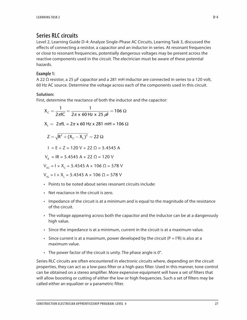
Example 1:A 22 Ω resistor, a 25 μF capacitor and a 281 mH inductor are connected in series to a 120 volt, 60 Hz AC source. Determine the voltage across each of the components used in this circuit.
Solution:First, determine the reactance of both the inductor and the capacitor:
XfC x Hz x FC = = =
12
12 60 25
106π π µ
Ω
X fLL = = 2 x 60 Hz x 281 mH = 1062π π Ω
Z R X XC L= + − =2 2 22( ) Ω
I = E ÷ Z = 120 V ÷ 22 Ω = 5.4545 A
VR = IR = 5.4545 A × 22 Ω = 120 V
VXC = I × XC = 5.4545 A × 106 Ω = 578 V
VXL = I × XL = 5.4545 A × 106 Ω = 578 V
• Points to be noted about series resonant circuits include:
• Net reactance in the circuit is zero.
• Impedance of the circuit is at a minimum and is equal to the magnitude of the resistance of the circuit.
• The voltage appearing across both the capacitor and the inductor can be at a dangerously high value.
• Since the impedance is at a minimum, current in the circuit is at a maximum value.
• Since current is at a maximum, power developed by the circuit (P = I2R) is also at a maximum value.
• The power factor of the circuit is unity. The phase angle is 0°.
Series RLC circuits are often encountered in electronic circuits where, depending on the circuit properties, they can act as a low-pass filter or a high-pass filter. Used in this manner, tone control can be obtained on a stereo amplifier. More expensive equipment will have a set of filters that will allow boosting or cutting of either the low or high frequencies. Such a set of filters may be called either an equalizer or a parametric filter.

LEARNING TASk 2 D-4
28 CONSTRUCTION ELECTRICIAN APPRENTICESHIP PROGRAM: LEVEL 4
All RLC series circuits have a resonant frequency. This resonant frequency can be obtained by applying the following formula:
fLCr =
12π
Example 2:A resistor, an inductor and a capacitor are connected in series to a 120 volt, variable-frequency source. For this circuit, R = 860 Ω, L = 30 mH and C = 0.22 μF. Determine the resonant frequency of this circuit.
Solution:
fLC x x x
kHzr = = =− −
12
1
2 30 10 0 22 101 959
3 6π π ..
For the analysis of series RLC circuits, three approaches can be used. Recall that in a series circuit, current has the same value throughout and is used as the reference in vector diagrams. Three types of vector diagrams can be used to analyze series RLC circuits:
• Voltage vector diagrams
• Impedance diagrams
• Power diagrams
Each of the following Pythagorean formulas is valid in a series RLC circuit (assume XL is greater than XC):
E V V V
Z R X X
VA P AR AR
R L C
L C
= + −
= + −
= + −
2 2
2 2
2 2
( )
( )
( )V s V sL C
Parallel RLC circuitsA characteristic of parallel RLC circuits that must be noted is that the same voltage appears across all parallel branches. The inductive branch of this circuit will be a practical inductor, which consists of a resistive component and an inductive component. Parallel RLC circuits are best represented as shown in Figure 8.

LEARNING TASk 2 D-4
CONSTRUCTION ELECTRICIAN APPRENTICESHIP PROGRAM: LEVEL 4 29
Figure 8—Parallel RLC circuit
Recall that series RLC circuits can be analyzed using impedance, voltage and power vector diagrams. The method used most often to solve parallel RLC circuit problems involves using power vector diagrams.
Example 3:For the circuit illustrated in Figure 8, the source voltage is 120 volts, 60 Hz, and the other circuit components are R = 100 Ω, RCOIL = 20 Ω, ICOIL = 3 A, and C = 50 µF. For this circuit, determine the:
a. total circuit current
b. power factor of the total circuit
Solution:ZCOIL = 120 V ÷ 3 A = 40 Ω
XL = − =40 20 34 642 2 . Ω
P100 Ω = 1202 V ÷ 100 Ω = 144 W
PCOIL = (3 A)2 × 20 Ω = 180 W
VARs lag = (3 A)2 × 34.64 Ω = 311.76 VARs lag
XC = 1 ÷ 2πfC = 53.05 Ω
VARs lead = (120 V)2 ÷ 53.05 Ω = 271.43 VARs lead
VARs net = 311.76 VARs lag − 271.43 VARs lead = 40.33 VARs net
PT = 144 W + 180 W = 324 W
VA VAT = + =324 40 33 326 52 2. .
a. IT = 326.5 VA ÷ 120 V = 2.72 A
b. PF = W ÷ VA = 324 W ÷ 326.5 VA = 0.992 lagging

LEARNING TASk 2 D-4
30 CONSTRUCTION ELECTRICIAN APPRENTICESHIP PROGRAM: LEVEL 4
In a practical RLC circuit, when the VARs lagging are equalled by the VARs leading in the circuit, the circuit impedance will be at a maximum and the current drawn from the line will be at a minimum. The power factor of the circuit will be unity, with the total circuit volt-amperes equalling the total wattage dissipated.
Remember that the individual currents in the reactive branches of the circuit are not zero. Their overall effect in the circuit is zero because they are 180° out of phase, and cancel each other out. The branch currents may, in fact, be quite large. For the circuit analyzed in Example 3, most of the coils magnetizing VARs are supplied by the capacitor; only a small portion are supplied by the line.
Selection of power factor correction capacitors in single-phase AC circuitsThe consequences of a low power factor in a load can be illustrated by considering an example of a practical RLC circuit.
Example 4:Essentially, a single-phase AC motor is a load that consists of a resistance component and a reactive component. Suppose that when a loaded, single-phase motor is connected to a 120 V, 60 Hz source, a current of 15 amperes is drawn. A wattmeter can be used to determine that 1260 watts are being used.
The power factor of this motor (ignoring the consideration of efficiency for this example) can now be determined by applying the following formula:
PFWVA
WV A
WVA
= = = =1260
120 1512601800
0 7x
lagging.
Theoretically, if the original motor is replaced by a motor capable of developing a true power of 1260 watts at 100% power factor, the apparent power (VA) drawn from the source will now be 1260 VA. The current drawn from the source for this motor can be determined:
IVAE
= = =1260 VA
120 V10.5 A
Figure 9 illustrates that the current drawn from the line has been reduced to 10.5 A from the original current of 15 A.
M
A
15 A
1260 W70% lagging PF
120 V60 Hz
(a)
M
A
10.5 A
1260 W100% PF
120 V60 Hz
(b)
Figure 9—Single-phase RLC circuit
Since the current drawn from the line is significantly reduced, the size of the wire used to supply the line current could be reduced. In addition, the wire size used in the generator

LEARNING TASk 2 D-4
CONSTRUCTION ELECTRICIAN APPRENTICESHIP PROGRAM: LEVEL 4 31
or transformer supplying the line could also be reduced. Also, since the copper losses in the system are dependent on the magnitude of the square of the current, it becomes more economical for the utility company to supply the requirements of the load operating at 100% power factor, which draws significantly less current.
A power triangle has been developed in Figure 10 to illustrate the previous example:
1800 VA1285 VARs
1260 Wa. PF = 0.7
1260 Wb. PF = 1
Figure 10—Using the power triangle
The reactive power, or VARs, required by the inductive reactance of the motor can be calculated using the Pythagorean theorem:
VARs VA W 1800 1260 1285 VARs2 2 2 2= − = − =
Power factor correction consists of adding capacitive reactive power to an AC circuit in such a manner that the apparent power (VA) drawn from the source is reduced without altering the current through or the voltage across the load itself.
To obtain an overall unity power factor, and thus minimize the current drawn from the line, it is necessary to connect a capacitor having a reactive power equal to the reactive power of the load in parallel with the load. The consequences of incorrectly placing a capacitor in series with the load will be discussed later.
The selection of a power factor correction capacitor requires the consideration of several factors, including:
• Voltage rating
• Frequency rating
• kVAR rating
• Number of phases
This important information is listed on the nameplate of an industrial capacitor used for power factor correction. Assuming that we have chosen a single-phase, 120 V, 60 Hz capacitor, rated for 1285 VARs, and have correctly connected this capacitor in parallel with the load, the circuit should now be corrected to unity power factor. It is now possible for the capacitor and the inductance of the load to trade their reactive power back and forth without the reactive component of the current having to be drawn from the source through the line. Figure 11 illustrates this situation.

LEARNING TASk 2 D-4
32 CONSTRUCTION ELECTRICIAN APPRENTICESHIP PROGRAM: LEVEL 4
Figure 11—Correcting PF using a capacitor
Note that the capacitor has been added in such a manner that the current through and the voltage across the load have not been altered. Also, note that the vector representation of this circuit should not be analyzed using current triangles. A more accurate result is obtained using power triangles, as illustrated in Figure 12.
VA of
moto
r
1260 VA1260 W
1285 VARs leading
1285 VARs lagging
Figure 12—Resulting power triangle
It is also possible to calculate the µF rating of the capacitor used, but first you must calculate the capacitive reactance XC:
XE
VARsV
1285 VARs
C1
2 fX1
2
C
2
C
= = =
= =
( ).
12011 2
2
Ω
π π xx 60 x 11.2236.8 F
Ω= µ

LEARNING TASk 2 D-4
CONSTRUCTION ELECTRICIAN APPRENTICESHIP PROGRAM: LEVEL 4 33
Note that the capacitive reactance of this capacitor (XC) is inversely dependent upon the frequency of the circuit. If the source frequency was decreased, the capacitive reactance would increase. Also, if the frequency was increased, the capacitive reactance would decrease. The VARs rating of the capacitor is dependent on frequency as well.
Since VARs are determined using the formula
VARsEXC
=2
,
XC increases with a reduction of source frequency, then as long as the source voltage remains the same, the capacitive VARs in the circuit will decrease.
Remember to carefully examine the nameplate of a power factor correction capacitor before you connect it into a circuit. If the capacitor rated for 120 V that was used in this example were incorrectly connected across a 240 V source, then the capacitor may not be able to withstand the stress. The stress may damage the dielectric (insulation).
Consideration should also be given to the situation where the capacitor selected is incorrectly connected in series into the circuit. A series circuit is best examined using impedance triangles.
In the motor circuit example:
ZEI
R Z PF
XL
= = =
= = =
=
120 V15 A
8
x 8 x
Ω
Ω Ω0 7 5 6
82
. .
−− =5 6 5 712. . Ω
The impedance triangle looks like that shown in Figure 13.
R = 5.6 Ω
X = 5.71 ΩL
Z = 8 Ω
Figure 13—Using the impedance triangle
If the 236.8 µF capacitor is added in series with the load, the circuit now becomes an RLC series circuit. The reactance XC is found to be:
XfC FC = =
× ×=
12
12 60 236 8
11 2π π .
. Ω
The impedance triangle with the addition of the series-connected capacitor now looks like that shown in Figure 14.

LEARNING TASk 2 D-4
34 CONSTRUCTION ELECTRICIAN APPRENTICESHIP PROGRAM: LEVEL 4
Xc = 11.2 Ω
Xnet = 5.49 Ω
XL = 5.71 Ω
R = 5.6 Ω
Z = 7.8
4 Ω
Figure 14—Series RLC circuit
The impedance (Z) can be determined as:
Z R X XC L= + − = + − =2 2 2 25 6 11 2 5 71 7 84( ) ( . ) ( . . ) .Ω Ω Ω Ω
Current in the circuit is:
IEZ
VA= = =
1207 84
15 3.
.Ω
Note that this new line current of 15.3 A is much higher that the 10.5 A value that was obtained when the capacitor was connected in parallel with the motor load. The voltage across the capacitor in this series circuit is calculated as:
V IXX CC= = 15 3. A x 11.2 = 171.4 VΩ
This voltage level exceeds the 120 V rating of the capacitor that was selected when mistakenly placed in series with the motor load.

LEARNING TASk 2 D-4
CONSTRUCTION ELECTRICIAN APPRENTICESHIP PROGRAM: LEVEL 4 35
Partial power factor correctionMost often, the addition of a capacitor results in partial power factor correction. This is demonstrated by the following example.
Example 5:A fully-loaded 5 horsepower motor with an efficiency of 84%, draws 28 amperes when connected to a 240 V, 60 Hz supply.
a. Determine the power factor of the motor as connected.
b. Determine the requirements of the capacitor that could be used to correct the overall power factor of the circuit to 91% lagging.
c. Determine the new line current after the capacitor is added.
Solution:a. A power triangle will be used to solve this problem. The first step will be to determine the
volt-amperes (VA) supplied to the load:
VA = E x I = 240 V x 28 A = 6720 VA
Now determine the output power that the motor develops:
P hpout = =5 x 746
Whp
3730 W
Considering the efficiency of the motor, determine the input power to the motor:
Pinput = = =
PEfficiency
3730 W0.84
4440.5 Wout
The power factor of the motor may now be determined as:
PF= = =
P
VA4440.5 W6720 VA
lagginginput 0 661.
b. When solving this part of the question, it must be remembered that the input power drawn by the motor will not change with the addition of a power factor correction capacitor. There will, however, be a new circuit VA and a lower line current. The new circuit VA can be determined as:
VA =
P
PF4440.5 W
0.914879.7 VAnew
input
new
= =
The total VARs in the circuit can be determined:
LEARNING TASk 2 D-4
36 CONSTRUCTION ELECTRICIAN APPRENTICESHIP PROGRAM: LEVEL 4
VARs VA Pnew input= −
= −
=
( ) ( )2 2
4879.7 VA 4440.5 W
20
2 2
223.2 VARs lagging
In order to determine the ratings of the capacitor added to the circuit, we must determine the VARs added. First, calculate the VARs that were in the motor circuit before the addition of the capacitor:
VARs VA Pinput= −
= −
=
( ) ( )2 2
6720 VA 4440.5 W
5043.8
2 2
VVARsoriginal
Now, determine the VARs added:
VARs = VARs VARs
VARs = 5043
added original new
added
−
..8 VARs 2023.2 VARs = 3020.6 VARs−
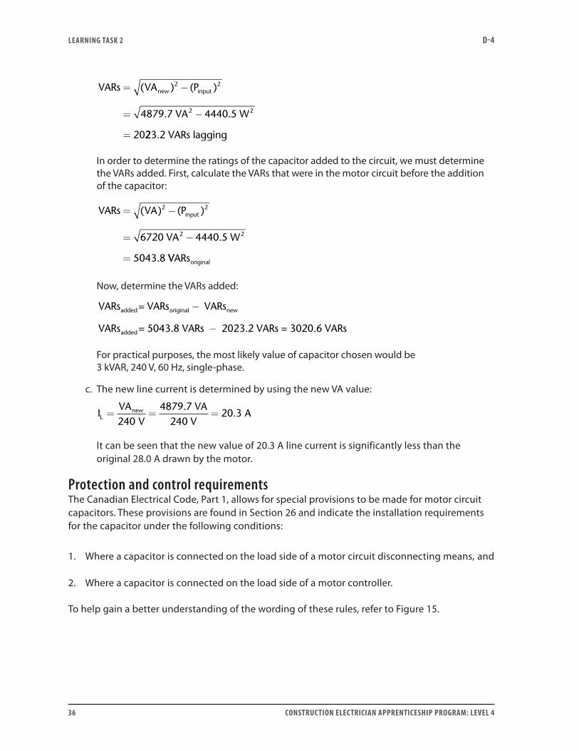
For practical purposes, the most likely value of capacitor chosen would be 3 kVAR, 240 V, 60 Hz, single-phase.
c. The new line current is determined by using the new VA value:
I
VAL
new= = =240
20 3V
4879.7 VA240 V
A.
It can be seen that the new value of 20.3 A line current is significantly less than the original 28.0 A drawn by the motor.
Protection and control requirementsThe Canadian Electrical Code, Part 1, allows for special provisions to be made for motor circuit capacitors. These provisions are found in Section 26 and indicate the installation requirements for the capacitor under the following conditions:
1. Where a capacitor is connected on the load side of a motor circuit disconnecting means, and
2. Where a capacitor is connected on the load side of a motor controller.
To help gain a better understanding of the wording of these rules, refer to Figure 15.

LEARNING TASk 2 D-4
CONSTRUCTION ELECTRICIAN APPRENTICESHIP PROGRAM: LEVEL 4 37
To supply
Motor feederdisconnect
Motor feederO/C protection
Motor feederconductors
Motor branchcircuit disconnect
Motor branch circuitO/C protection
Motor branchcircuit conductors
Motor starter
Motor supply conductors
MCC bus
D
C
B
A
Figure 15— Riser diagram for motor circuit
The motor starter in this example can also be interpreted as the motor controller for the purpose of applying these special provisions. Point A is the most efficient location to use for correcting power factor in motor circuits. If the capacitors are connected at this location, the rating or setting of the overload device must be reduced to a value corresponding to the current obtained with the improved power factor. Also, the capacitor is automatically switched by the motor starter and is only energized when the motor is running.
If the capacitors are connected at Point B, the overload device need not be reduced. If the capacitors are located at Points A or B, consideration must be given to situations that generate over-voltage and over-torque. These situations are discussed in the CEC in Section 26, and include both jogging and plugging applications.

LEARNING TASk 2 D-4
38 CONSTRUCTION ELECTRICIAN APPRENTICESHIP PROGRAM: LEVEL 4
Capacitors located at Point C would not prevent the motor from being used for jogging or plugging applications. The capacitors are not switched by the motor starter and would remain connected to the MCC bus for as long as the motor branch circuit disconnect remains closed.
If capacitors are installed at Point D, then a disconnecting means and overcurrent device that satisfies the CEC provisions listed in Section 26 must be installed. This method would likely be the most cost effective for power factor correcting a group of small motors.
Applications involving single-phase AC motorsPractical AC circuits often contain impedances in parallel. For example, a single-phase motor can be connected in parallel with a baseboard heater. In these sorts of circuits, the motor (at full load) will be operating at a certain power factor and efficiency. These factors must be taken into consideration.
Example 6:A 2 horsepower, single-phase motor operating at full load is connected in parallel with a baseboard heater to a 120 volt, 60 Hz line. The efficiency of the motor is 82% and the motor operates at a power factor of 79% lagging. The baseboard heater dissipates 1.2 kW at a unity power factor. Determine the:
a. true power developed by this circuit
b. overall power factor of this circuit
Solution:Pout = 2 hp × 746 W/hp = 1492 W
Pin = POUT ÷ efficiency = 1492 W ÷ 0.82 = 1819.5 W
VAmotor = PIN ÷ PF = 1819.5 ÷ 0.79 = 2303.2 VA
VARsmotor
VARs= − =( . ) ( . ) .2303 2 1819 5 1413 42 2
a. The true power developed by this circuit is the sum of the watts for the motor plus the watts for the baseboard heater:
P P P
W W
W
T M HTR= +
= +
=
1819 5 1200
3019 5
.
.
b. The overall PF of the circuit is the ratio of the total watts to the total volt-amps of the circuit, or in this case the cosine of the circuit phase angle.
LEARNING TASk 2 D-4
CONSTRUCTION ELECTRICIAN APPRENTICESHIP PROGRAM: LEVEL 4 39
tan.
..
.
cos .
θ
θ
= =
= °
=
1413 43019 5
0 4681
25 08
25 0
VARsW
PF 88
0 9057 90 6
°
= . . %or lagging
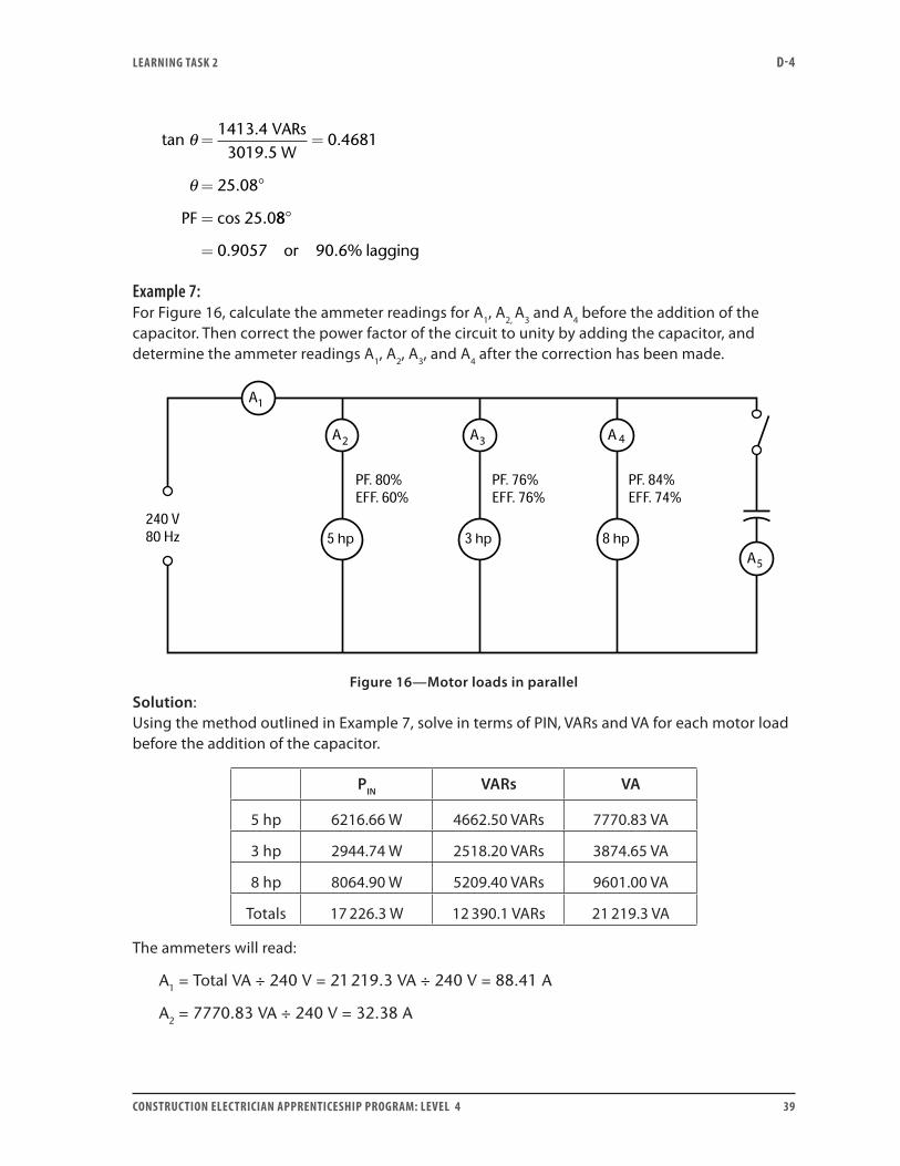
Example 7:For Figure 16, calculate the ammeter readings for A1, A2, A3 and A4 before the addition of the capacitor. Then correct the power factor of the circuit to unity by adding the capacitor, and determine the ammeter readings A1, A2, A3, and A4 after the correction has been made.
1
22 3 4
5
Figure 16—Motor loads in parallelSolution:Using the method outlined in Example 7, solve in terms of PIN, VARs and VA for each motor load before the addition of the capacitor.
PIN VARs VA
5 hp 6216.66 W 4662.50 VARs 7770.83 VA
3 hp 2944.74 W 2518.20 VARs 3874.65 VA
8 hp 8064.90 W 5209.40 VARs 9601.00 VA
Totals 17 226.3 W 12 390.1 VARs 21 219.3 VA
The ammeters will read:
A1 = Total VA ÷ 240 V = 21 219.3 VA ÷ 240 V = 88.41 A
A2 = 7770.83 VA ÷ 240 V = 32.38 A

LEARNING TASk 2 D-4
40 CONSTRUCTION ELECTRICIAN APPRENTICESHIP PROGRAM: LEVEL 4
A3 = 3874.65 VA ÷ 240 V = 16.14 A
A4 = 9601 VA ÷ 240 V = 40 A
Now, the switch supplying the capacitor is closed, correcting the circuit to unity power factor. The value that the ammeters will now read must be determined:
VA total is now equal to P total = 17 226.3 VA.
A1 = IT = 17 226.3 VA ÷ 240 V = 71.78 A
A5 = 12 390.1 VARs leading ÷ 240 V = 51.6254 A
Ammeters A2, A3 and A4 read the same values as previously.
Applications involving single-phase transformersThree fundamental characteristics about single-phase transformers should be reviewed. In Level 2, Learning Guide I-2: Install Transformers, Learning Task 1, a relationship between the voltage ratio and turns ratio was discussed. The following equation was developed based on this relationship:
Point 1:
EE
NN
EN
EN
P
S
P
S
P
P
S
S
transpose this= =
The transposed formula implies that the volts-per-turn induced in the primary coil must be equal to the volts-per-turn in the secondary coil. This is an easy-to-remember statement that can be applied to enable the electrician to solve many transformer problems.
Point 2:
A relationship exists enabling the primary current to automatically adjust itself so that the change in ampere-turns in the primary winding is always equal but opposite to the change in ampere-turns in the secondary winding. Two equations can be derived from the ampere-turn relationship of the primary and secondary currents:
II
NN
IP
S
S
PP= NN I NP S S=
transpose this
The equation on the right is an easy-to-remember statement that can also enable the electrician to solve many transformer problems.

LEARNING TASk 2 D-4
CONSTRUCTION ELECTRICIAN APPRENTICESHIP PROGRAM: LEVEL 4 41
Point 3:
Finally, neglecting the very small losses (due to eddy currents, hysteresis losses, stray flux, I2R losses in the primary and secondary windings, etc.) a third key point may be stated as:
The power into a transformer is always equal to the power out of the transformer.
VAin = VAout or restated EPIP = ESIS
Example 8:A 2 kVA transformer has a primary voltage rating of 480 volts, and a turns ratio of 4:1. If a 10 Ω resistive load is connected across the secondary terminals, determine the:
a. rated current of the secondary
b. actual current in the primary with the 10 Ω load connected on the secondary
Solution:a. IS = 2000 VA ÷ 120 V = 16.66 A
b. IS = ES ÷ R = 120 V ÷ 10 Ω = 12 A
VAin = VAout, and EPIP = ESIS, therefore 480 V × IP = 120 V × 12 A
And
IP = (120 V × 12 A) ÷ 480 V = 3 A
Transformer polarityThe polarity of any given terminal of the primary winding is determined by the supply voltage, and changes every half-cycle. The instantaneous polarity of the terminals of any other winding, however, is determined by the direction of flux, and therefore has some direction relative to that of the primary. In the illustration shown in Figure 17, the terminals are arbitrarily marked. At the instant shown, terminal A is connected to the negative terminal of the supply. In order to oppose the flux set up by the primary winding (in accordance with Lenz’s law), current must flow into terminal D and out of terminal C. This current is caused by the induced emf in the secondary winding, and as with the polarity of a generator, terminal C is now the negative one. A and D are thus terminals of opposite polarity, as are B and C. It should be obvious that if the secondary winding were wound in the opposite direction, the polarities of the secondary terminals would be opposite to those shown.
It should be further noted that, at the instant shown in the Figure 4, the induced primary voltage must oppose current I1 and therefore, is in the direction from B to A. The induced emf in the secondary, however, actually sets up current I2 and is therefore in the direction from D to C. Terminals B and D are thus said to have the same relative polarity, and consequently terminals A and C have the same relative polarity. The relative polarity, therefore, may be taken with respect to induced voltage or with respect to current. With a unity-power factor load, there is little difference, since the secondary current is almost in phase with the secondary induced voltage. If, however, the power factor is not unity, during some part of the cycle the current may actually be leaving terminal D at the same instant that the current is entering terminal A. Induced voltages

LEARNING TASk 2 D-4
42 CONSTRUCTION ELECTRICIAN APPRENTICESHIP PROGRAM: LEVEL 4
are therefore taken as the basis for determining polarity, since they are independent of the type of load. Moreover, it is unnecessary to load the transformer in order to determine relative polarity of the terminals.
The terminals of the high-voltage winding of a transformer are normally marked with the letter H followed by a numbered subscript. The terminals of the low-voltage winding of a transformer are normally marked with the letter X followed by a numbered subscript. The numbers indicate the relative polarity of the induced voltages in the two windings. These terminal markings are used when it is desirable to parallel transformers, connect multi-coil transformers, connect three-phase transformer banks, or connect metering and protective relaying.
Two tests can be performed to test for transformer polarity. These tests are referred to as the AC voltmeter test and the DC inductive kick test. (Level 2, Learning Guide I-2: Install Transformers, Learning Task 5 should be reviewed for a detailed explanation of these testing procedures.)
Figure 17—Transformer polarity
Transformers connected in parallelAn electrician may be called upon to connect two or more transformers into a bank to supply a load. Certain conditions must be met before transformers can be successfully paralleled:
• The transformers must have the same primary and secondary voltage ratings.
• When making the connections, you must observe the terminal polarity of the transformers.
• All the transformers must have the same percent impedance.
A bank of transformers connected in parallel will have a kVA rating that is simply the sum of the individual kVA ratings. The available fault current from a bank of transformers is simply the sum of the available fault currents of the individual transformers. (A sample problem is included in Self-Test 2 in which three transformers are connected in parallel to supply a load. )

LEARNING TASk 2 D-4
CONSTRUCTION ELECTRICIAN APPRENTICESHIP PROGRAM: LEVEL 4 43
Transformer tap connectionsTo compensate for line drop and transformer percent voltage regulation, some transformers are equipped with tap changers that allow adjustable turns ratios. Generally, there are two categories: no-load tap changers and on-load tap changers.
No-load tap changers incorporate a break-before-make switch. Whenever the switch is moved, it breaks the primary circuit before making the new connection. Changes in transformer turn ratios using a no-load tap changer must be made on a de-energized transformer. Any attempt to adjust the tap changer switch while the primary is still connected may result in loss of life and serious equipment damage.
On-load tap changers are specially designed and intended to be used while the circuit is energized.
Example 9:Consider the multi-tap transformer illustrated in Figure 18.
600–120 V
Figure 18—Multi-tap transformer
Your computer is supplied by this 600 V–120 V multi-tap transformer, and you desire to maintain voltage across the load as close as possible to 120 volts. If the line voltage supplying the transformer primary drops to 560 volts:
a. What is the voltage that will appear across your computer load?
b. What would be the best tap connection to choose to improve this situation, and what would be the voltage across the computer terminals after the change is made?
Solution:a. The voltage ratio is 600 V to 120 V, which is a 5:1 ratio. If 560 V is applied, the secondary
voltage will be 560 V ÷ 5 = 112 V.
b. Assume that the primary has 600 turns when connected to the 100% tap. If the source voltage is connected to the 94% tap, how many turns are utilized?
600 turns × 94% = 564 turns

LEARNING TASk 2 D-4
44 CONSTRUCTION ELECTRICIAN APPRENTICESHIP PROGRAM: LEVEL 4
The volts-per-turn value can be obtained:
EP =NP
560 V564 turns
= 0.99291 voltsturn
The number of turns on the secondary will be:
600=turns ratio
= 120 turnsNSNP
5=
The volts per turn of the secondary winding will equal the volts per turn of the primary winding, enabling us to now determine the secondary voltage:
=
120 turns0.99291 volts
turnES
ES = 0.99291 × 120 = 119.15 volts
AutotransformersAutotransformers are transformers that have an electrically conductive link between the primary and the secondary windings. Some of the turns are shared by both windings. Autotransformers are normally used:
• Where a small increase or decrease in voltage is required
• For reduced-voltage starting of squirrel-cage induction motors
• In power supplies where multiple voltages are required
• In automatic voltage regulators to compensate for line drop as load changes occur
The following relationships that apply for standard transformers also apply for autotransformers:
VAin = VAout (neglecting losses)
EE
NN
P
S
P
S
=
II
NN
P
S
S
P
=
A standard two-winding transformer may be used as an autotransformer by simply making an electrical connection between the high-voltage and low-voltage windings. Connected in this manner, there are four possible ways to utilize this two-winding transformer. How we make the connections will depend on the source voltage available and the voltage requirements of the load. (A detailed discussion of autotransformers can be found in Level 2, Learning Guide I-2: Install Transformers, Learning Task 12.)

LEARNING TASk 2 D-4
CONSTRUCTION ELECTRICIAN APPRENTICESHIP PROGRAM: LEVEL 4 45
For example, a 15 kVA, 600 V–120 V single-phase, standard two-winding transformer can be connected as an autotransformer to satisfy the following four conditions:
• Where the supply voltage available is 600 V and the load requirement is 720 V.
This configuration is called a boost connection, and when operated in this way, the 15 kVA transformer can supply a 90 kVA load.
• Where the supply voltage available is 600 V and the load requirement is 480 V.
This configuration is called a buck connection, and when operated in this way, the 15 kVA transformer can supply a 60 kVA load.
• Where the supply voltage available is 120 V and the load requirement is 720 V.
This configuration is called a boost connection, and when operated in this way, the 15 kVA transformer can supply a 18 kVA load.
• Where the supply voltage available is 120 V and the load requirement is 480 V.
This configuration is called a buck connection, and when operated in this way, the 15 kVA transformer can supply a 12 kVA load.
Example 10:A 220 V–440 V, 3 kVA transformer is used to build a 440–660 V step-up autotransformer to supply a unity power factor load.
a. Draw a diagram of the connection identifying:
• H1, H2, X1 and X2
• Theinstantaneouspolaritymarkingsforthetransformerwindingsandtheload
• Thedirectionofthecurrentsenteringandleavingalljunctions
b. Calculate the maximum current through:
• Eachtransformerwindingatratedload
• Theunitypowerfactorload
• Thelinesupplyingtheautotransformer
c. Determine the rated kVA of the load.

LEARNING TASk 2 D-4
46 CONSTRUCTION ELECTRICIAN APPRENTICESHIP PROGRAM: LEVEL 4
Solution:a.
3
3
3
Figure 19—Autotransformer boost configuration
b. I3 = 3000 VA × 220 V = 13.64 A = Iload
I2 = 3000 VA × 440 V = 6.82 A
I1 = I3 + I2 = 13.64 A + 6.82 A = 20.46 A
c. VAout = 660 V × 13.64 A = 9002.4 VA
Note: I1 can also be calculated as:
I1 = 9002.4 VA × 440 V = 20.46 A
Troubleshooting two-wire and three-wire distribution circuitsA problem that may occur is an open developing in one of the line conductors in a three-wire AC circuit. This situation may be the result of an excessive load in one of the lines resulting in one of the fuses possibly opening. Consider the following example.
Example 11:In the circuit shown in Figure 20, fuses F1 and F2 are rated at 100 A each. R1 = 4 Ω, R2 = 6 Ω, and R3 = 3 Ω. Under these conditions:
a. Determine which fuse will open due to excessive loading.
Once this fuse has blown:
b. Determine the expected voltmeter readings for V1 to V9.

LEARNING TASk 2 D-4
CONSTRUCTION ELECTRICIAN APPRENTICESHIP PROGRAM: LEVEL 4 47
V–
1
1
1
1
2
2
2
2 3
3
4 5
6
7 8
9
Figure 20—Circuit for Example 11
Solution:
a. By calculation, R1 draws 30 A, R2 draws 20 A, and R3 draws 80 A. Therefore, current in L1 is 110 A, current in L2 is 100 A and neutral current is 10 A.
b. This condition results in fuse F1 blowing. When fuse 1 opens, the circuit becomes a parallel-series combination circuit that can be redrawn to look like the circuit shown in Figure 21. The voltage across voltmeters 1 and 2 (not shown) will be 240 volts. The other voltmeter readings in the circuit are as follows:
V3 = 51.43 volts V4 = 188.6 volts
V5 = 0 volts V6 = 51.43 volts
V7 = 68.57 volts V8 = 120.0 volts
V9 = 51.43 volts

LEARNING TASk 2 D-4
48 CONSTRUCTION ELECTRICIAN APPRENTICESHIP PROGRAM: LEVEL 4
1
1
1
2
2
33
4
5 6
7
8
9
Figure 21—Open line problem
Observe that the voltage across voltmeter V4 is 188.6 volts. Many electricians may wonder why such an unusually high voltage appears across the open fuse F1 (see Figure 20).
Now do Self-Test 2 and check your answers.

LEARNING TASk 2 D-4
CONSTRUCTION ELECTRICIAN APPRENTICESHIP PROGRAM: LEVEL 4 49
Self-Test 2
1. A resistance baseboard heater is rated at 1.2 kW and 240 V, 60 Hz. What is its effective AC resistance?
2. If the baseboard heater in Question 1 was operated at 120 V, 60 Hz, what would be the power developed?
3. A resistive soldering iron is rated at 100 W, 120 V, 60 Hz. It is desired to reduce its heat output for use in a transistorized circuit. A suggestion is to place a resistor in series with the AC supply to the iron, in order to limit the power to 25 W. What is the ohms/watts rating required for this resistor?
4. It is desired to limit the current in a 10 Ω resistor to 0.5 A when connected to a 120 V, 60 Hz supply. What is the ohms/watts rating of series-connected resistor required?
5. Two 500 kΩ resistors are connected in series to a 100 V, 60 Hz supply. A multimeter is used to measure the voltage drop across one of the resistors. If the meter has a sensitivity of 5000 ohms per volt on the 100 V AC scale, what would be the reading expected on the meter?
6. Two resistors when connected in parallel to a 120 V, 60 Hz supply draw a total current of 10 A. When a third resistor is connected in parallel, the total current is now 13 A. What is the ohmic value of the third resistor?
7. For the circuit shown in Figure 1, determine:
a. the supply voltage (ET)
b. the total power

LEARNING TASk 2 D-4
50 CONSTRUCTION ELECTRICIAN APPRENTICESHIP PROGRAM: LEVEL 4
Figure 1—Circuit for Question 7
8. In Figure 1, if the 150 Ω resistor was now removed from the circuit:
a. Would the circuit power increase or decrease?
b. Would the line current increase or decrease?
9. For the three-wire circuit shown in Figure 2, calculate the current in the neutral conductor.
120–240 V60 Hz
Figure 2—Circuit for Question 9

LEARNING TASk 2 D-4
CONSTRUCTION ELECTRICIAN APPRENTICESHIP PROGRAM: LEVEL 4 51
10. In Figure 2, if fuse A blows (opens), what would be the:
a. current in the neutral conductor
b. voltage measured across the blown (open) fuse
11. A series RLC circuit consisting of an 8 Ω resistor, a 620 µF capacitor and a practical inductor that has a resistance component of 4 Ω and an inductive component of 43 mH, is connected to a 120 volt, 60 Hz source. Determine the:
a. total current drawn by the circuit
b. voltage drop across the practical inductor
c. total power factor of the circuit
12. A series circuit is constructed using a 12 Ω resistor, a pure 40 mH inductor and a 80 µF capacitor. Determine the:
a. current drawn by the circuit when connected to a 120 volt AC source at resonant frequency
b. voltage across the capacitor when connected to a 120 volt AC source at resonant frequency
13. A 10 Ω resistor, a 265.3 μF capacitor and a practical inductor are connected in series to a 120 volt, 60 Hz source. The inductor has a resistance of 5 Ω and an inductance of 66.3 mH. Determine:
θcircuit = Zcircuit = Vcoil =
VR = VARs = VA =
P = Iline = Vcapacitor =
XL = XC = Zcoil =
14. A parallel RLC circuit consisting of a 30 Ω resistor, an inductor having an inductive reactance of 20 Ω and a capacitor having an capacitive reactance of 60 Ω, is connected to a 240 volt, 60 Hz AC source. Determine:
a. the total current drawn by the circuit
b. the power factor of the circuit

LEARNING TASk 2 D-4
52 CONSTRUCTION ELECTRICIAN APPRENTICESHIP PROGRAM: LEVEL 4
c. the true power dissipated in the circuit
d. the frequency at which the circuit will be at resonance
15. The total current drawn by a parallel RL circuit is 12 amps when connected to a 240 volt, 60 Hz source. The inductor has a value of 65 mH. Determine the size (ohms/watts) of the resistor used and the power factor of this circuit.
16. A resistor, an inductor and a capacitor are connected to a 120 volt variable-frequency AC source. The resistor has a value of 20 Ω, the inductor has a value of 25 mH, and the capacitor is of an unknown value. The frequency of the source is adjusted until the line current is at a minimum. This frequency is determined to be 72 Hz. Determine the value of the unknown capacitor in μF.
17. A 7.5 horsepower motor has an efficiency of 85% and a power factor of 71% lagging when operating at full load and connected to a 240 volt, 60 Hz source. Determine the new line current after a capacitor is installed to correct the power factor to 91% lagging.
18. A motor that is connected to a 120 volt, 60 Hz, single-phase supply has a 150 µF power factor correction capacitor connected across its terminals, resulting in an overall circuit power factor of 91.6% lagging. Before connecting the capacitor to the circuit, the motor took 1400 W from the supply. What was the original circuit power factor?
19. List four factors that must be considered when selecting capacitors for power factor correction.

LEARNING TASk 2 D-4
CONSTRUCTION ELECTRICIAN APPRENTICESHIP PROGRAM: LEVEL 4 53
20. A resistor, a capacitor and an inductor are connected in parallel to a 120 volt, 60 Hz source. The circuit is operating at a unity power factor. If the source frequency is increased, the power factor of the circuit would:
a. go leading
b. go lagging
c. stay the same
d. become 0%
Explain how you determined your answer.
21. For the circuit shown in Figure 3, determine the current readings for the following ammeters:
A1 = A A2 = A
A3 = A A4 = A
A5 = A A6 = A
laglag laglag
1 2 3 4
5 6
Figure 3—Loads in parallel

LEARNING TASk 2 D-4
54 CONSTRUCTION ELECTRICIAN APPRENTICESHIP PROGRAM: LEVEL 4
22. What value of capacitor (in μF) would have to be installed in parallel with the circuit illustrated in Figure 3, in order to correct the power factor of the circuit to a value of 0.95 lagging?
23. A variable frequency AC supply is connected to a parallel circuit that consists of:
• A rheostat (set at the mid point)
• A tapped variable inductor (connected at tap position 2) with the core inserted half way
• A trimmer capacitor, and
• A variable capacitor
Figure 4—How to improve power factor
If the circuit, connected as illustrated, has a lagging power factor, list six different methods that could be used to improve the power factor closer to unity.
•
•
•
•
•

LEARNING TASk 2 D-4
CONSTRUCTION ELECTRICIAN APPRENTICESHIP PROGRAM: LEVEL 4 55
•
24. An additive-polarity, single-phase transformer has its low-voltage winding connected to a 120 volt source. The secondary has 60 turns and is connected to a 40 Ω load resistor. If the number of turns in the primary is 40 and the transformer is fully loaded, determine the:
a. primary line current
b. secondary voltage of the transformer
c. secondary current of the transformer
d. VA rating of the transformer
e. voltage ratio, and turns ratio
25. A three-wire distribution system is installed utilizing a 2400 V – 120 V/240 V transformer. Six equal resistors of 12 Ω are installed across L1 and the grounded neutral. Four equal resistors of 16 Ω are installed across L2 and the neutral. For this circuit, determine:
a. the minimum kVA requirement for the transformer used
b. the current in the neutral
c. the primary current
Use the multi-tap transformer in Figure 5 to answer Questions 26 and 27.
2400–120 V
Figure 5—Multi-tap transformer
LEARNING TASk 2 D-4
56 CONSTRUCTION ELECTRICIAN APPRENTICESHIP PROGRAM: LEVEL 4
26. The secondary of the transformer is measured to be 120 volts. If the source voltage is connected to the 105% tap of the primary, determine the primary source voltage value.
27. When the source voltage is connected to the 95% tap, a voltage of 118.95 volts is measured across the secondary terminals. Determine the primary source voltage.
28. A dry-type transformer rated at 6 kVA, 240 V–120 V is used to supply a balanced three-wire load. The transformer is protected by non-time delay fuses on the primary side, which are installed in a fused disconnect. This fused disconnect is fed from a 240 V, single-phase splitter. All conductors used in this circuit are R90XLPE copper and are installed in EMT. Determine the:
a. minimum calculated ampacity for the primary conductors
b. minimum AWG size required for the primary conductors
c. minimum size of the raceway used for the primary conductors
d. minimum calculated ampacity for the secondary conductors
e. minimum AWG size required for the secondary conductors
f. minimum size of the raceway used for the secondary conductors
g. maximum fuse size that can be used to provide overcurrent protection
h. the minimum grounding requirements for the secondary

LEARNING TASk 2 D-4
CONSTRUCTION ELECTRICIAN APPRENTICESHIP PROGRAM: LEVEL 4 57
29. Complete Figure 6 by connecting the instruments in the metering circuit, making sure that all the polarities are correct.
V
M M
1:3 300:1
T
PT
1:1 T
160:1
75 hp 5 hp 32 kW
W
CT
R
η = 93.25%PF = 92.31%
E I
η = 93.25%PF = 80%
A
2
1
1
1
Figure 6—Single-phase AC metering circuit
30. Given the information contained in Figure 6, calculate the:
a. primary and secondary values of voltage and current for transformer T1
b. primary and secondary values of voltage and current for transformer T2
31. Determine the reading of each of the meters used in Figure 6
32. Determine the multiplier for the wattmeter used in the circuit shown in Figure 6

LEARNING TASk 2 D-4
58 CONSTRUCTION ELECTRICIAN APPRENTICESHIP PROGRAM: LEVEL 4
33. A single-phase transformer has 1000 turns in one winding and 250 turns in a second winding. This transformer is to be used in a step-up application with a 110 volt, 60 Hz source connected to the primary winding. A resistive load is connected to the secondary terminals, and this load draws a current of 20 amperes. Determine the:
a. secondary voltage
b. primary current
34. Three transformers are operated in parallel to supply a 240 V bus from a 2400 V bus. All three transformers have a 2.5% impedance.
• Transformer 1 is rated 50 kVA, 2400 V − 120 V/240 V subtractive polarity.
• Transformer 2 is rated 75 kVA, 2400 V/4800 V − 240 V/480 V subtractive polarity.
• Transformer 3 is rated 37.5 kVA, 1200 V/2400 V − 120 V/240 V subtractive polarity.
a. Complete the schematic illustrated in Figure 7, labelling all connections.
b. Determine the total kVA rating for the bank.
c. Determine the full-load current ratings for the bank.
d. Determine the full-load current ratings of each transformer, as connected.
e. Determine the full-load current ratings of each transformer winding.
f. Determine the available fault current for each transformer.
g. Determine the available fault current for the transformer bank.

LEARNING TASk 2 D-4
CONSTRUCTION ELECTRICIAN APPRENTICESHIP PROGRAM: LEVEL 4 59
Figure 7—Paralleling transformers
35. A 600 V–240 V, 7.5 kVA transformer is used to build a 600 V–360 V step-down autotransformer to feed a unity power factor load.
a. Draw a diagram of the connection, identifying the:
• H1, H2, X1 and X2 terminals
• Instantaneous polarity markings for the transformer windings and the load
• Direction of the currents entering and leaving all junctions
b. Calculate the maximum current through:
• Each transformer winding at rated load
• The unity power factor load
• The lines supplying the autotransformer
c. Determine the rated kVA of the load.

LEARNING TASk 2 D-4
60 CONSTRUCTION ELECTRICIAN APPRENTICESHIP PROGRAM: LEVEL 4
36. For the three-wire circuit shown in Figure 8, the wattage shown are what each load is rated for. If an open develops in the line at the point marked X, determine the voltage that will now appear across each load and across the break.
2
Figure 8—Open line problem

LEARNING ObjECTIVES D-4
CONSTRUCTION ELECTRICIAN APPRENTICESHIP PROGRAM: LEVEL 4 61
37. In the circuit illustrated in Figure 9, F1 and F2 are fuses rated at 100 amperes each, and R1 = 4 Ω, R2 = 6 Ω and R3 = 3 Ω. Considering these conditions, which fuse will blow? Determine all nine of the voltmeter readings under this open line condition.
V–
1
1
1
1
2
2
2
2 3
3
4 5
6
7 8
9
Figure 9—Three-wire circuit
Go to the Answer Key at the end of the Learning Guide to check your answers.

62 CONSTRUCTION ELECTRICIAN APPRENTICESHIP PROGRAM: LEVEL 4

ANSwER kEY D-4
CONSTRUCTION ELECTRICIAN APPRENTICESHIP PROGRAM: LEVEL 4 63
Answer key
Self-Test 11. in phase
2. The instantaneous power values are plotted by using the product of the instantaneous current times the instantaneous voltage at a given point (degrees) in time.
3. No. However, it is sinusoidal about a line drawn midway between zero and the instantaneous maximum value.
4. Because mathematically, a negative times a negative results in a positive value.
5. average power (which is the product of ERMS × IRMS)
6. square wave, sawtooth wave
7. One is the reciprocal (inverse) of the other.
8. a. effective (or RMS)
b. average
9. a. 106 A
b. 0 A
10. greater than 170 V
11. 118 A
12. 500 W
13. 73.5 V
14. 30°
15. lags by 90
16. harmonic
17. (repeat Figure 8 in LT-1)
18. counterclockwise

ANSwER kEY D-4
64 CONSTRUCTION ELECTRICIAN APPRENTICESHIP PROGRAM: LEVEL 4
19. closed, open
20. –1.5 volts
Self-Test 21. 48 Ω
2. 300 W
3. 144 Ω, 25 W
4. 230 Ω, 57.5 W
5. 33.3 V
6. 40 Ω
7. a. 240 V
b. 1680 W
8. a. decrease
b. decrease
9. 5 A
10. a. 18.33 A
b. 160 V
11. a. 7.09 A
b. 118.3 V
c. 0.709 lagging
12. a. I = 10 A
b. VXC = 223.61 V

ANSwER kEY D-4
CONSTRUCTION ELECTRICIAN APPRENTICESHIP PROGRAM: LEVEL 4 65
13.
θ circuit = 45° lagging Zcircuit = 21.21 Vcoil = 144.25 V
VR = 56.58 V VARs = 480 VARs lagging
VA = 679 VA
P = 480 W Iline = 5.65 A Vcapacitor = 56.58 V
XL = 25 XC = 10 Zcoil = 25.495
14. a. 11.314 A
b. 0.707 lagging
c. 1920 W
d. 103.923 Hz
15. R = 34.6 Ω/1662 W and PF = 0.5776 lagging
16. 195.45 µF
17. 30.14 A
18. 70% lagging
19. voltage rating, frequency rating, kVAR rating, number of phases
20. a. PF goes leading
f ; X ; X ; I ; I ; VARs ;L C XL XC XL⇑ ⇑ ⇓ ⇓ ⇑ ⇓ VVARs ; PF goes leadingXC ⇑
21. A1 = 603.93 A A2 = 431.7 A
A3 = 232.02 A A4 = 120 A
A5 = 200 A A6 = 120 A
22. 1536 μF
23. 1. Increase the frequency of the supply.
2. Turn the rheostat wiper in a clockwise direction.
3. Connect the jumper on the inductor to position #1.
4. Adjust the iron core further into the coil windings.

ANSwER kEY D-4
66 CONSTRUCTION ELECTRICIAN APPRENTICESHIP PROGRAM: LEVEL 4
5. Adjust the trimmer capacitor so that the distance between plates is smaller.
6. Adjust the adjustable capacitor so that the plate area increases.
24. a. 6.75 A
b. 180 V
c. 4.5 A
d. 810 VA
e. 1:1.5 voltage ratio, 1:1.5 turns ratio
25. a. 14.4 kVA
b. 30 A
c. 4.5 A
26. 2520 V
27. 2260 V
28. a. 31.25 A
b. #8 AWG
c. 1/2 inch (16) metric designator (mm)
d. 62.5 A
e. #6 AWG
f. 3/4 inch (21) metric designator (mm)
g. 35 A
h. #8 AWG (with protection)
29. See Figure 1.

ANSwER kEY D-4
CONSTRUCTION ELECTRICIAN APPRENTICESHIP PROGRAM: LEVEL 4 67
V
M M
1:3 300:1
T
PT
1:1 T
160:1
75 hp 5 hp 32 kW
W
CT
R
η = 93.25%PF = 92.31%
E I
η = 93.25%PF = 80%
A
2
1
1
1 120 V
Figure 1—Answer for Self-Test 2 Question 29
30. a. EP = 12 kV, ES = 36 kV, IP = 8.33 A, IS = 2.77 A
b. EP = 36 kV, ES = 225 V, IP = 2.78 A, IS = 444.4 A
31. voltmeter = 120 V, ammeter = 2.778 A, wattmeter = 320 W
32. 300 times
33. a. 440 V
b. 80 A
34. a. See Figure 2.
b. 162.5 kVA
c. IP = 67.708 A IS = 677.08 A
d. Transformer 1 IP = 20.830 A IS = 208.30 A
Transformer 2 IP = 31.249 A IS = 312.49 A
Transformer 3 IP = 15.625 A IS = 156.25 A
e. Transformer 1 IP = 20.830 A IS = 208.30 A each winding
Transformer 2 IP = 15.625 A IS = 156.25 A each winding

ANSwER kEY D-4
68 CONSTRUCTION ELECTRICIAN APPRENTICESHIP PROGRAM: LEVEL 4
Transformer 3 IP = 15.625 A IS = 156.25 A each winding
f. Transformer 1 IS (Fault) = 8333.3 A
Transformer 2 IS (Fault) = 12 500.0 A
Transformer 3 IS (Fault) = 6250.0 A
g. Bank fault current = 27 083.3 A
Figure 2—Paralleling transformers
35. a.
Figure 3—Autotransformer buck configuration

ANSwER kEY D-4
CONSTRUCTION ELECTRICIAN APPRENTICESHIP PROGRAM: LEVEL 4 69
b. I3 = 7500 VA ÷ 240 V = 31.25 A = Iload
I2 = 7500 VA ÷ 600 V = 12.50 A
I1 = I3 – I2 = 31.25 A – 12.50 A = 18.75 A
c. VAout = 360 V × 31.25 A = 11 250 VA
Note that I1 can also be calculated as:
I1 = 11 250 VA ÷ 600 V = 18.75 A
36. V1 = 120 volts V2 = 48 volts
V3 = 120 volts V4 = 72 volts
V5 = 72 volts Vbreak = 168 volts
37. Fuse 1 will blow.
V1 = 240 V V2 = 240 V V3 = 51.43 V
V4 = 188.6 V V5 = 0 V V6 = 51.43 V
V7 = 68.5 V V8 = 120 V V9 = 51.43 V

ANSwER kEY D-4
70 CONSTRUCTION ELECTRICIAN APPRENTICESHIP PROGRAM: LEVEL 4


7960003458
ISBN 0-7726-6439-0
9 780772 664396