
Learn Build Play - Growl
49
Assembly Manual Tweed Deluxe 5E3 Instructions for Assembling with the: - Printed Circuit Board (PCB) with additional modification suggestions and recommended amp settings version 14 19 December 2011 Learn Build Build Play
Transcript of Learn Build Play - Growl

Assembly ManualTweed Deluxe 5E3
Instructions for Assembling with the:- Printed Circuit Board (PCB)
with additional modification suggestions and recommended amp settings
version 1419 December 2011
Learn BuildBuild Play

This manual was developed and published by:
TubeDepot.comMemphis, TN
Written by:Robert Hull
Edited by:Mary Klaebel
Design and artwork by:Robert HullMary KlaebelChristian Magee
Acknowledgements:Special thanks to:
Joe Austin Brian OverstreetMatt Kirby Doug SimsHenry Lum Ben Siler
Special Thanks to Steve Zeller, Todd Fox, Skip Black, Jake Swiatek and Henk Haitjema for their invaluable proof reading skills.
Copyright © 2009TubeDepot.com1686 Barcrest Dr.Memphis, TN 38134(877)[email protected]
REGARDING THESE BOOK MATERIALSReproduction, publication, or duplication of this booklet, or any part thereof, in any manner, mechanically, electronically, or photographically is prohibited without the express written permission of the publisher.
The Author, Publisher or Seller assume no liability with respect to the use of the information contained herein.
For permission and other rights under this copyright, contact TubeDepot.com.
ii TubeDepot.com
pagePreface and Deluxe overview ........................................................................................................ iv
Chapter 1Safety …......................................................................................................................... 1
Chapter 2Tools and Supplies …..................................................................................................... 2
Chapter 3Parts Inventory ...........................…................................................................................ 3
Chapter 4Cabinet Preparation …................................................................................................... 4
Chapter 5Circuit Assembly (PCB)….............................................................................................. 5
Chapter 6Chassis Preparation and Assembly …......................................................................... 10
Chapter 7Final Assembly …......................................................................................................... 19
Chapter 8Testing …..................................................................................................................... 20
Chapter 9Schematics and Parts Layout ….................................................................................. 23
Chapter 10Cool Modifications …................................................................................................... 27
Appendix A. How to Read Resistor and Capacitor Codes …....................................................... 28B. Soldering Hints ….................................................................................................... 31C. Amplifier Care, Feeding, and Application Hints …................................................... 33D. Drilling Templates …................................................................................................ 35E. Test Equipment ….................................................................................................... 38
TubeDepot.com iii
Table of Contents

Short History of the Tweed Fender Deluxe
The tweed deluxe amplifier has become the “go to” amp when looking for maximum portability and raw, uncompromising tone. With two 6V6 tubes and a single 12” speaker, the tone of this amp is nothing short of amazing. Used by a “who's who” list of musicians, this amp's tone can be found on records, in studios, and on stage around the globe.
With enough power to comfortably sing above the average electrified band, the original Fender Deluxe was first introduced in the early 50's as one of Fender's new line of tweed amps. It had two 6SL7 metal preamp tubes, two 6V6 power tubes, and a 5Y3 rectifier tube.
With the introduction of the new 12AY7 and 12AX7 preamplifier tubes (replacing the two 6SL7 metal tubes), by 1957 the power output was brought to 15W into a 12” Jensen AlNiCo speaker. With these improvements, the iconic amp and tone was born.
It is this incarnation that we provide for you here.
The tweed deluxe is one of my favorite amps. Inside its diminutive size rests the heart of an entire world of music. From blues, to rock-a-billy; from rock-n-roll to soul; from country to jazz, this amp is capable of holding its own across a wide swath of musical history and genres. When it comes to walking into a gig with only a guitar in one hand and an amp in the other, there is no other amp that can provide this depth of expression in such a simple package.
Therefore imagine my excitement in designing a kit where you can build an incredible amp on which to put your musical mark on the world. Wow … this is going to be fun!
Thank you for purchasing this great kit. You should be able to easily put this kit together in an evening or two … whether you have any prior amp building experience or not. I designed this kit for you to enjoy both building and playing. And once finished, this kit will allow you to make the best music you can and to leave your mark on the world.
Now, let's have some building and playing fun.
Robert HullDirector of Technical ServicesTubeDepot.com
TM
TMTM
TM
iv TubeDepot.com
Preface
!!! Read these safety precautions before continuing !!! ALL tube amplifiers contain LETHAL VOLTAGES, often several hundred volts which WILL leave burnt entrance and exit wounds in skin. These voltages have the potential to cause permanent physical damage and death. These voltages are present when the amp is turned on and also for some time after the amp has been turned off. You can still get shocked with a tube amp turned off and disconnected from AC power.
The above statement is a bit scary, but we want to stress that every piece of electronic equipment must be treated with respect. When AC power is applied, there is always a chance for injury or death. With tube amps, even when the AC power is not applied there is still danger. Being shocked with high voltage is very painful and we do not want anyone finding out the hard way.
When building this kit, we want your experiences to be both enjoyable and safe. There are more kits to assemble and we want you to enjoy building and playing them all.
Throughout this manual at key points in the construction, we have annotated important steps with the below alerts. For your safety and to improve construction quality, It is important that you become familiar with each of these alerts and adhere to their recommendations when they appear.
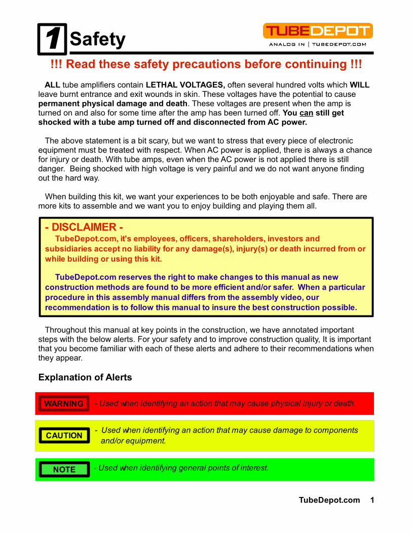
Explanation of Alerts
TubeDepot.com 1
1 Safety
CAUTION
NOTE
- Used when identifying an action that may cause damage to components and/or equipment.
- Used when identifying general points of interest.
- Used when identifying an action that may cause physical injury or death.WARNING
- DISCLAIMER - TubeDepot.com, it's employees, officers, shareholders, investors and subsidiaries accept no liability for any damage(s), injury(s) or death incurred from or while building or using this kit.
TubeDepot.com reserves the right to make changes to this manual as new construction methods are found to be more efficient and/or safer. When a particular procedure in this assembly manual differs from the assembly video, our recommendation is to follow this manual to insure the best construction possible.

As with any construction project, there are certain tools and supplies that are recommended to complete the project. These are tools and supplies not provided with the kit and are instead provided by the builder.
TubeDepot.comThe following is our recommended list: part number
Phillips screwdriver, #1 and #2 TL-VTSCRSET8 Slip joint pliersNeedle nose pliers TL-VT33 Wire cutters, diagonal TL-VT33Wire strippers, for 18 and 20 awg wire TL-VT5021 Electric Drill (cordless recommended)Drill bit, 3/16” - Chassis mounting into the cabinetDrill bit, 5/32” - PCB and turret board chassis mountingMasking tape, 2”Ruler or scale, 12” w/ 1/16” markingsPermanent marker, fine tipSoldering iron, 25W – 40W (35W recommended) TL-WP35 Solder, electronics safe (60/40 w/ rosin core recommended) TS-24-6040-0027 Flux, electronic – liquid or paste (must be safe for electronic work) TS-83-1000-0186 De-soldering pump extractor TS-384-1000 Solder wick TS-1817-10F Sponge
The following are really nice to have:
Soldering station w/ temperature control TL-WTCPT Multimeter w/ DC range of at least 500V TL-DVM850BL Variable AC supply (Variac® style)Current Limiting AC source (dim bulb tester) – self builtNeedle nose pliers – small size, for electronics work TL-NN7776 Wire cutters, diagonal – small size, for electronics work TL-170M Center punchNutdrivers - 5/16”, 11/32”, 7/16”, 1/2”Square, 9”Scratch AwlDe-burring tool TL-DB-1Fingernail polish (for holding nuts and screws in place)
2 TubeDepot.com
2 Tools and Supplies

It is important to review all the parts that came with your kit. The list below is what you should have received to complete your kit. If you find anything missing, contact us:
Qty Description Speaker, Chassis, Cabinet, PC Board1 speaker, 12" Jensen MOD, 8ohms1 chassis, steel chrome plated deluxe 5E31 cabinet, tweed deluxe 5E31 PCB board, 5E3 Transformers1 transformer, high performance power BF deluxe w/ export taps1 transformer, high performance output BF deluxe, 8 ohm Tubes1 5AR4 / GZ34 rectifier tube various brands2 6V6GT beam power tetrode various brands2 12AX7 / ECC83 dual triode various brands Hardware, Cabinet (provided with cabinet)4 bolt 1 1/2” 6x32 copper plated truss screw baffle mounting bolts4 bolt 1 1/2” 8x32 flat head, black oxide coated speaker mounting bolts4 nuts, KEPS 6x32 baffle mounting nuts4 nuts, KEPS 8x32 speaker mounting nuts1 handle, brown flat leather w/ mounts and screws handle assembly4 feet, metal glide w/ screw glide feet8 screw, #6 oval head phillips, 1 1/4” stainless steel back panel screws Hardware, General3 knob, vintage pointer volume and tone knob1 fuse holder, conical cap, vintage style fuse holder1 fuse, 3AG 2A slow-blow fuse1 lamp holder indicator lamp holder1 jewel, red red jewel1 lamp, #47, 6.3 V lamp4 jack, 12A, shorting, Switchcraft ¼" input jacks2 jack, 11A, open, Switchcraft ¼" speaker output jacks9 washer, lock; 3/8" lock washer for jacks and potentiometers1 plug, Switchcraft ¼" speaker phone plug2 switch, toggle SPST; Carling power and standby switches2 washer, lock 1/2” lock washer for switches1 power cord, grounded three prong, 12' power cord1 strain relief, Heyco strain relief1 nylon cable clamp cable clamp1 screw, zinc plated #8 x 5/8", phillips flat head cable clamp screw2 grommets, rubber 3/8" hole rubber chassis grommets4 washer, neoprene bonded speaker mounting2 bolt, 1 1/2" 10x32 truss screw chassis mounting2 nuts, KEPS 10x32 chassis mounting10 screw, zinc plated 6-32 x 1/4", phillips pan head tube socket mounting13 nuts, KEPS 6x32 tube socket / PC board mounting1 nuts, 6x32 preamp tube socket mounting4 screw, zinc plated 6-32 x 1/2" phillips pan head PC board mounting4 standoff, nylon; L = .25"; id = .140"; od = .250" PC board mounting4 nuts, KEPS 8x32 power / output xfmr mounting2 nuts, 8x32 power xfmr mounting2 screw, zinc plated 8-32 x 1/4", phillips pan head output xfmr mounting1 screw, zinc plated #6 philips pan head back panel ground connection2 solder lug, locking, #8 screw power xfmr mounting / chassis ground
TubeDepot.com 3
Parts Inventory3
TubeDepot.com1686 Barcrest Dr.Memphis, TN 38134(877) [email protected]

2 solder lug, locking, #6 screw preamp tube socket amount / chassis ground1 header, 3 pin / two position feedback select1 shorting jumper feedback select20” alum. tape, 2" width, self adhesive (2 pieces) electrical and temperature shielding2 heat shrink, 1/8" - black, 6" piece insulation, wire dressing Tube Sockets2 socket, tube, miniature 9 pin preamp tube sockets3 socket, tube, octal, 8 pin power and rectifier tube sockets Resistors2 100, 1/2w carbon film pseudo filament center tap1 820, 1/2w carbon film cathode resistor4 68K, 1/2w carbon film input resistor3 1M, 1/2w carbon film preamp tube grid biasing3 100K, 1/2w carbon film plate resistor4 1.5K, 1/2w carbon film cathode resistor2 56K, 1/2w carbon film bias resistor2 220K, 1/2w carbon film power tube grid biasing1 2.7K, 1/2w carbon film feedback resistor1 47, 1/2w carbon film feedback resistor1 250, 5w metal oxide power tube cathode resistor1 4.7K, 3w metal oxide B+ voltage divider resistors1 22K, 1w metal oxide B+ voltage divider resistors2 470, 2w metal oxide screen grid resistors Capacitors1 500pfd / 500V tone capacitors1 .0047ufd / 630V tone capacitors1 .022ufd / 630V coupling capacitors4 .1ufd / 630V coupling capacitors1 .01ufd / 630V coupling capacitor (alternate part for C7 position)3 22ufd / 50V cathode bypass capacitors3 22ufd / 500V power supply filter capacitors Potentiometers3 1M audio volume and tone controls Wire10 wire, 20 awg, stranded, hi-temp PVC – yellow general signal wiring8 wire, 20 awg, stranded, hi-temp PVC – red B+ and input signal wiring8 wire, 20 awg, stranded, hi-temp PVC – black ground4 wire, 18 awg, stranded, hi-temp PVC – green filament wiring2 wire, 18 awg, stranded, hi-temp PVC – black speaker2 wire, 18 awg, stranded, hi-temp PVC – white speaker8 wire, 20 awg, solid buss wire, tinned copper ground wire across volume and tone controls
Parts for shock mounting the V1 tube socket (if desired)2 grommet, rubber 1/4" chassis hole / #6 screw2 screw, zinc plated 6-32 x 3/8", phillips pan head 2 washer, flat zinc plated, #6 screw-----------------------------------------------------------
Alternative parts for conversion to fixed bias operation (not included with standard kit)1 1N4007 rectifier bias supply rectifier1 470, 1w metal oxide bias supply current limiting resistor1 100ufd / 100V electrolytic capacitor bias supply filter capacitor1 10K, 1/2w carbon film bias supply voltage divider1 10K trim potentiometer bias supply variable voltage control1 1.0 ohm, 1W metal oxide resistor fixed bias cathode resistor1 terminal strip, 6 position bias supply terminal strip
4 TubeDepot.com
This chapter deals with preparing the cabinet for installation of the completed chassis. But first, we need to take inventory of the parts that came installed on the cabinet.
1. Handle w/ mounting hardware – There should be a single flat brown leather handle with two metal securing ends all fastened to the cabinet with four screws.
2. Feet, chrome metal glide – There should be four metal feet attached with screws to the underside of the cabinet.
3. Back panels, upper and lower with screws – There should be two back panels. The top back panel should be secured with four panel screws, the bottom panel should be secured with four panel screws.
4. Baffle bolts with nuts – There should be four bronze plated bolts attaching the baffle to the cabinet. The baffle is secured with four KEPS nuts, one on each of these bolts.
5. Speaker bolts with nuts – There should be four black oxide coated bolts for securing the speaker to the baffle board. Additionally, there should be four KEPS nuts, one on each of these bolts to be used when mounting the speaker.
Drilling for the Two Chassis Mounting Bolts
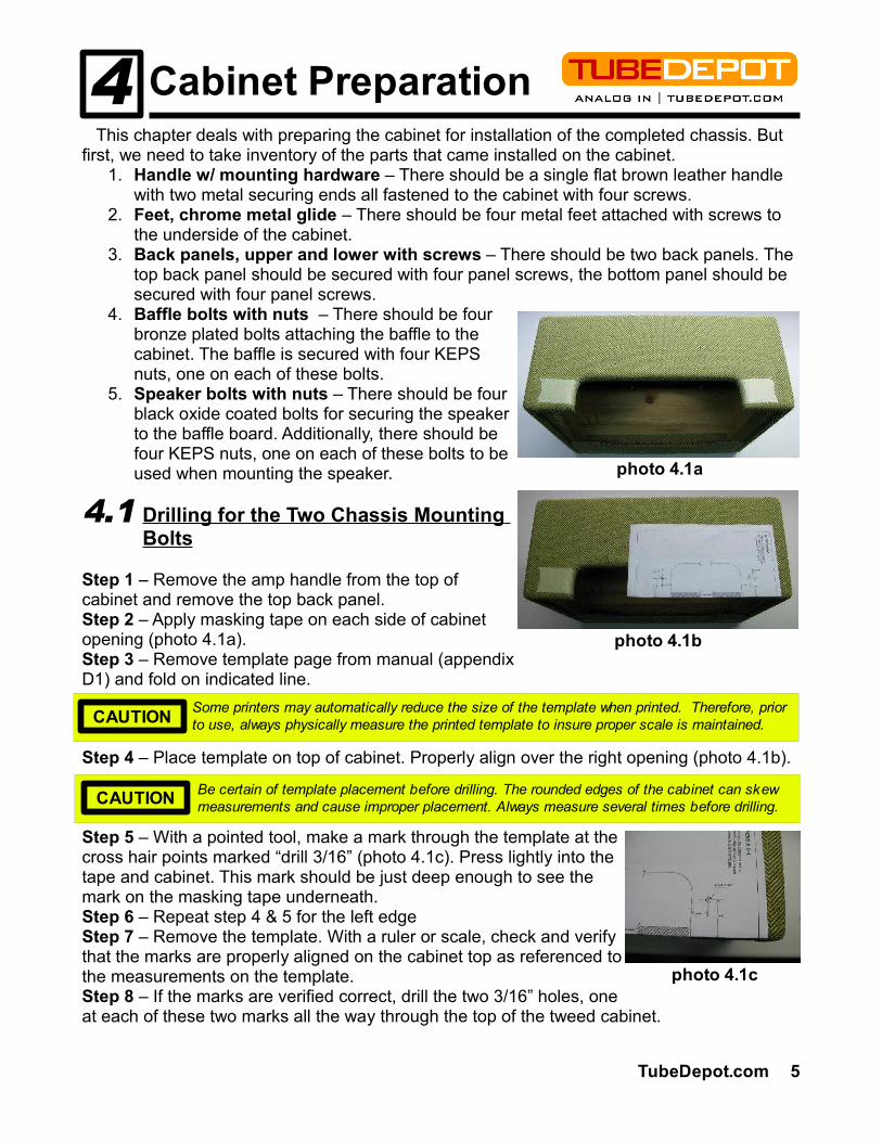
Step 1 – Remove the amp handle from the top of cabinet and remove the top back panel.Step 2 – Apply masking tape on each side of cabinet opening (photo 4.1a).Step 3 – Remove template page from manual (appendix D1) and fold on indicated line.
Step 4 – Place template on top of cabinet. Properly align over the right opening (photo 4.1b).
Step 5 – With a pointed tool, make a mark through the template at the cross hair points marked “drill 3/16” (photo 4.1c). Press lightly into the tape and cabinet. This mark should be just deep enough to see the mark on the masking tape underneath.Step 6 – Repeat step 4 & 5 for the left edgeStep 7 – Remove the template. With a ruler or scale, check and verify that the marks are properly aligned on the cabinet top as referenced to the measurements on the template.Step 8 – If the marks are verified correct, drill the two 3/16” holes, one at each of these two marks all the way through the top of the tweed cabinet.
Be certain of template placement before drilling. The rounded edges of the cabinet can skew measurements and cause improper placement. Always measure several times before drilling.CAUTION
photo 4.1a
photo 4.1b
4.1
4 Cabinet Preparation
photo 4.1c
TubeDepot.com 5
Some printers may automatically reduce the size of the template when printed. Therefore, prior to use, always physically measure the printed template to insure proper scale is maintained.CAUTION
Step 9 – Remove the masking tape and clean up any loose splinters and / or tweed from the holes and install the chassis mounting bolts.Step 10 – Test fit the chassis onto the bolts to make sure the holes are properly aligned.Step 11 – Remove chassis and reinstall handle, leaving chassis mounting bolts installed.Proceed to 4.2
Installing the Speaker
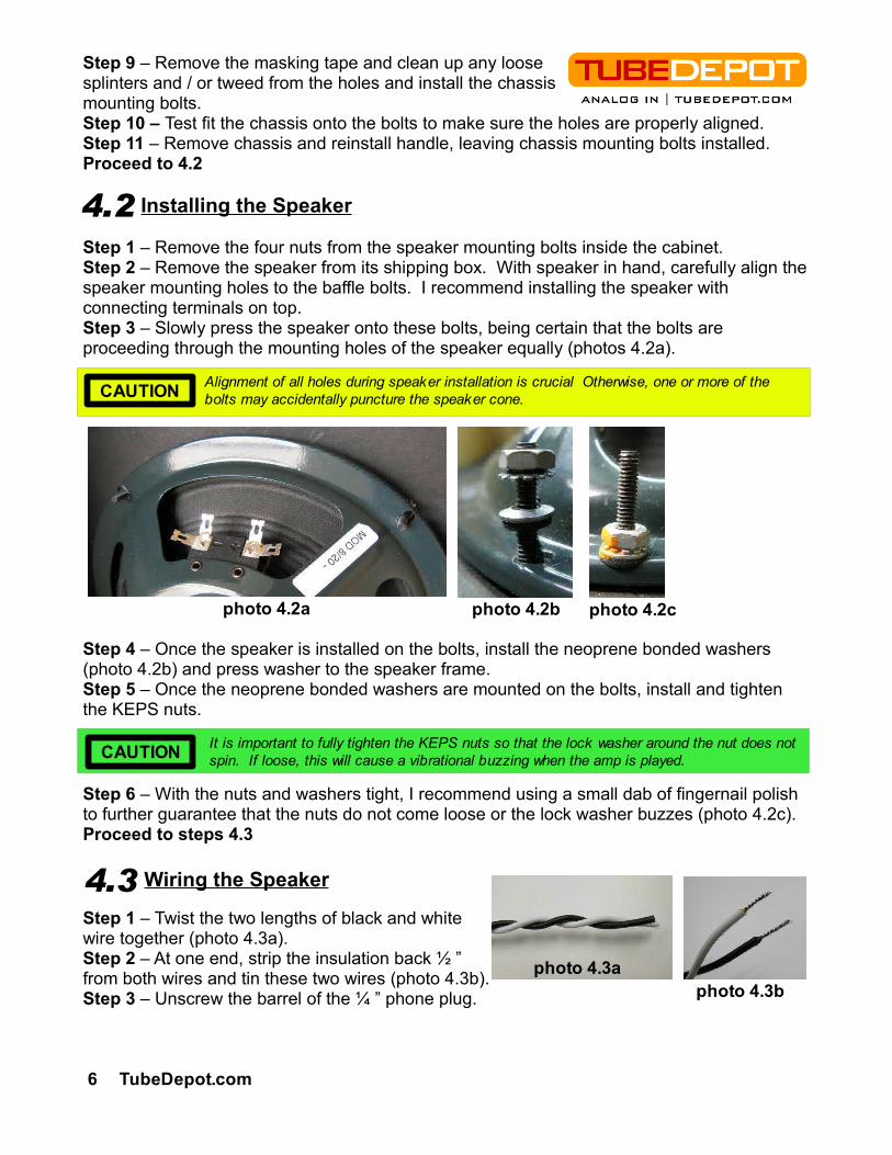
Step 1 – Remove the four nuts from the speaker mounting bolts inside the cabinet.Step 2 – Remove the speaker from its shipping box. With speaker in hand, carefully align the speaker mounting holes to the baffle bolts. I recommend installing the speaker with connecting terminals on top.Step 3 – Slowly press the speaker onto these bolts, being certain that the bolts are proceeding through the mounting holes of the speaker equally (photos 4.2a).
Step 4 – Once the speaker is installed on the bolts, install the neoprene bonded washers (photo 4.2b) and press washer to the speaker frame.Step 5 – Once the neoprene bonded washers are mounted on the bolts, install and tighten the KEPS nuts.
Step 6 – With the nuts and washers tight, I recommend using a small dab of fingernail polish to further guarantee that the nuts do not come loose or the lock washer buzzes (photo 4.2c).Proceed to steps 4.3
Wiring the Speaker
Step 1 – Twist the two lengths of black and white wire together (photo 4.3a). Step 2 – At one end, strip the insulation back ½ ” from both wires and tin these two wires (photo 4.3b).Step 3 – Unscrew the barrel of the ¼ ” phone plug.
Alignment of all holes during speaker installation is crucial Otherwise, one or more of the bolts may accidentally puncture the speaker cone.CAUTION
photo 4.2a
4.2
4.3
6 TubeDepot.com
photo 4.3a photo 4.3b
CAUTION It is important to fully tighten the KEPS nuts so that the lock washer around the nut does not spin. If loose, this will cause a vibrational buzzing when the amp is played.
photo 4.2b photo 4.2c
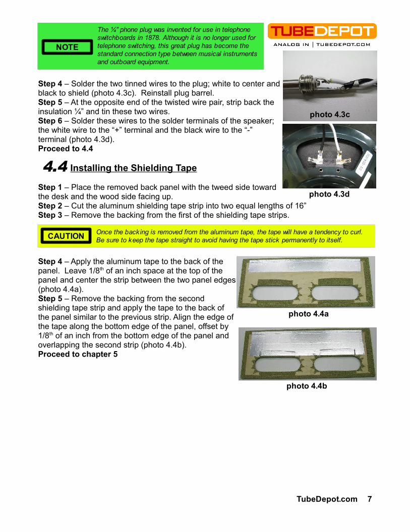
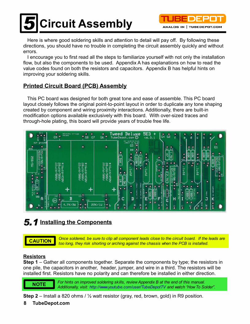
Step 4 – Solder the two tinned wires to the plug; white to center and black to shield (photo 4.3c). Reinstall plug barrel.Step 5 – At the opposite end of the twisted wire pair, strip back the insulation ¼” and tin these two wires.Step 6 – Solder these wires to the solder terminals of the speaker; the white wire to the “+” terminal and the black wire to the “-” terminal (photo 4.3d).Proceed to 4.4
Installing the Shielding Tape
Step 1 – Place the removed back panel with the tweed side toward the desk and the wood side facing up.Step 2 – Cut the aluminum shielding tape strip into two equal lengths of 16”Step 3 – Remove the backing from the first of the shielding tape strips.
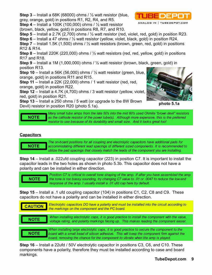
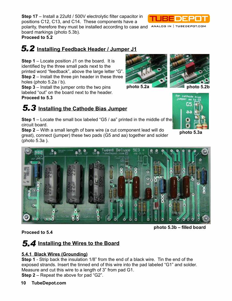
Step 4 – Apply the aluminum tape to the back of the panel. Leave 1/8th of an inch space at the top of the panel and center the strip between the two panel edges (photo 4.4a).Step 5 – Remove the backing from the second shielding tape strip and apply the tape to the back of the panel similar to the previous strip. Align the edge of the tape along the bottom edge of the panel, offset by 1/8th of an inch from the bottom edge of the panel and overlapping the second strip (photo 4.4b).Proceed to chapter 5
CAUTION Once the backing is removed from the aluminum tape, the tape will have a tendency to curl. Be sure to keep the tape straight to avoid having the tape stick permanently to itself.
photo 4.3d
4.4
photo 4.3c
photo 4.4b
NOTE
The ¼” phone plug was invented for use in telephone switchboards in 1878. Although it is no longer used for telephone switching, this great plug has become the standard connection type between musical instruments and outboard equipment.
TubeDepot.com 7
photo 4.4a
Here is where good soldering skills and attention to detail will pay off. By following these directions, you should have no trouble in completing the circuit assembly quickly and without errors. I encourage you to first read all the steps to familiarize yourself with not only the installation flow, but also the components to be used. Appendix A has explanations on how to read the value codes found on both the resistors and capacitors. Appendix B has helpful hints on improving your soldering skills.
Printed Circuit Board (PCB) Assembly
This PC board was designed for both great tone and ease of assemble. This PC board layout closely follows the original point-to-point layout in order to duplicate any tone shaping created by component and wiring proximity interactions. Additionally, there are built-in modification options available exclusively with this board. With over-sized traces and through-hole plating, this board will provide years of trouble free life.
Installing the Components
ResistorsStep 1 – Gather all components together. Separate the components by type; the resistors in one pile, the capacitors in another, header, jumper, and wire in a third. The resistors will be installed first. Resistors have no polarity and can therefore be installed in either direction.
Step 2 – Install a 820 ohms / ½ watt resistor (gray, red, brown, gold) in R9 position.
5 Circuit Assembly
5.1
NOTE For hints on improved soldering skills, review Appendix B at the end of this manual. Additionally, visit: http://www.youtube.com/user/TubeDepotTV and watch “How To Solder”.
8 TubeDepot.com
CAUTION Once soldered, be sure to clip all component leads close to the circuit board. If the leads are too long, they risk shorting or arching against the chassis when the PCB is installed.
Step 3 – Install a 68K (68000) ohms / ½ watt resistor (blue, gray, orange, gold) in positions R1, R2, R4, and R5.Step 4 – Install a 100K (100,000) ohms / ½ watt resistor (brown, black, yellow, gold) in positions R8, R7, and R10.Step 5 – Install a 2.7K (2,700) ohms / ½ watt resistor (red, violet, red, gold) in position R23.Step 6 – Install a 47 ohms / ½ watt resistor (yellow, violet, black, gold) in position R24.Step 7 – Install 1.5K (1,500) ohms / ½ watt resistors (brown, green, red, gold) in positions R12 & R14.Step 8 – Install 220K (220,000) ohms / ½ watt resistors (red, red, yellow, gold) in positions R17 and R18.Step 9 – Install a 1M (1,000,000) ohms / ½ watt resistor (brown, black, green, gold) in position R13.Step 10 – Install a 56K (56,000) ohms / ½ watt resistor (green, blue, orange, gold) in positions R11 and R15.Step 11 – Install a 22K (22,000) ohms / 1 watt resistor (red, red, orange, gold) in position R22.Step 12 – Install a 4.7K (4,700) ohms / 3 watt resistor (yellow, violet, red, gold) in position R21.Step 13 – Install a 250 ohms / 5 watt (or upgrade to the 8W Brown Devil) resistor in position R20 (photo 5.1a).
Capacitors
Step 14 – Install a .022ufd coupling capacitor (223) in position C7. It is important to install the capacitor leads in the two holes as shown in photo 5.3b. This capacitor does not have a polarity and can be installed in either direction.
Step 15 – Install a .1 ufd coupling capacitor (104) in positions C1, C2, C8 and C9. These capacitors do not have a polarity and can be installed in either direction.
Step 16 – Install a 22ufd / 50V electrolytic capacitor in positions C3, C6, and C10. These components have a polarity, therefore they must be installed according to case and board markings.
TubeDepot.com 9
CAUTION Electrolytic capacitors DO have a polarity and must be installed into the circuit according to the markings on the component and the PC board.
The on-board positions for all coupling and electrolytic capacitors have additional pads for accommodating different lead spacings of different sized components. It is recommended to utilize the pad spacings that closely match the leads of the component you are installing.
NOTE
When installing electrolytic caps, it is good practice to install the component with the value, voltage rating, and polarity markings facing up. This makes reading the component easier.NOTE
NOTEPosition C7 is critical to overall tone shaping of the amp. If after you have assembled the amp the tone is too bassy sounding, try changing C7 value to .01 or .0047 to reduce the low end response of the amp. I usually install a .01 ufd cap here by default.
NOTEWhen installing large electrolytic caps, it is good practice to secure the component to the board with a small bead of silicon adhesive. This will keep the component firm against the board, removing the chance for the component to vibrate when the amp is played.
NOTEMany small tube amps from the late 50's into the mid 60's used Ohmite “brown devil” resistors as the cathode resistor of the power tube(s). Although more expensive, this is the preferred resistor to use because of its durability and small size. And it looks great too!
photo 5.1a
Step 17 – Install a 22ufd / 500V electrolytic filter capacitor in positions C12, C13, and C14. These components have a polarity, therefore they must be installed according to case and board markings (photo 5.3b).Proceed to 5.2
Installing Feedback Header / Jumper J1
Step 1 – Locate position J1 on the board. It is identified by the three small pads next to the printed word “feedback”, above the large letter “G”.Step 2 – Install the three pin header in these three holes (photo 5.2a / b).Step 3 – Install the jumper onto the two pins labeled “out” on the board next to the header.Proceed to 5.3
Installing the Cathode Bias Jumper
Step 1 – Locate the small box labeled “G5 / aa” printed in the middle of the circuit board.Step 2 – With a small length of bare wire (a cut component lead will do great), connect (jumper) these two pads (G5 and aa) together and solder (photo 5.3a ).
Proceed to 5.4
Installing the Wires to the Board
5.4.1 Black Wires (Grounding)Step 1 - Strip back the insulation 1/8” from the end of a black wire. Tin the end of the exposed strands. Insert the tinned end of this wire into the pad labeled “G1” and solder. Measure and cut this wire to a length of 3” from pad G1.Step 2 – Repeat the above for pad “G2”.
5.2
10 TubeDepot.com
5.3
photo 5.2bphoto 5.2a
photo 5.3a
photo 5.3b – filled board
5.4

Step 3 – Repeat above for pad “G7” except extend wire to 4”.Step 4 – Repeat above for pad “G9” except extend wire to 6”.Proceed to 5.4.2
5.4.2 Red Wires (Circuit B+ and Preamp Tube Inputs)Step 1 - Strip back the insulation from the end of the red wire 1/8” and tin the end of the exposed strands. Insert the tinned end of this wire into the pad labeled “a” and solder. Measure and cut this wire to a length of 3” from pad “a”.Step 2 – Repeat above for pads “b”, “d”, and “e”.Step 3 – Repeat above for pads “x” and “y” except extend the wires to 3.5”.Step 4 – Repeat above for pad “j” except extend the wire to 3.5”.Proceed to 5.4.3
5.4.3 Yellow Wires (General Signal Routing)Step 1 - Strip back the insulation from the end of the yellow wire 1/8” and tin the end of the exposed strands. Insert the tinned end of this wire into the pad labeled “h” and solder. Measure and cut this wire to a length of 3” from pad “h”.Step 2 – Repeat above for pads “m”, “n”, “r”, “s”, “u”, “v”, “w”, and “z” except extend the wire to 3.5” for each.Step 3 – Repeat above for pad “c” and extend the wire to 5”.Step 4 – Repeat above for pads “f” and “t”, except extend the wires to 6”.Step 5 – Repeat above for pad “q” except extend the wire to 7”.Step 6 – Repeat above for pad “p” except extend the wire to 9”.Proceed to Chapter 6
TubeDepot.com 11
Drilling Mounting Holes for the Printed Circuit Board (PCB)
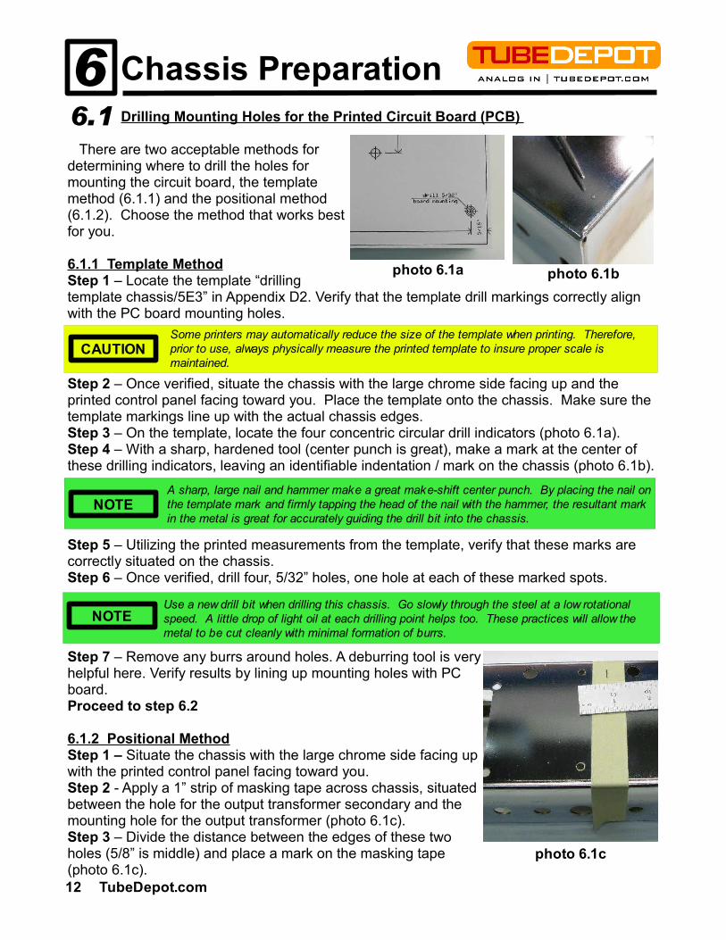
There are two acceptable methods for determining where to drill the holes for mounting the circuit board, the template method (6.1.1) and the positional method (6.1.2). Choose the method that works best for you.
6.1.1 Template MethodStep 1 – Locate the template “drilling template chassis/5E3” in Appendix D2. Verify that the template drill markings correctly align with the PC board mounting holes.
Step 2 – Once verified, situate the chassis with the large chrome side facing up and the printed control panel facing toward you. Place the template onto the chassis. Make sure the template markings line up with the actual chassis edges.Step 3 – On the template, locate the four concentric circular drill indicators (photo 6.1a).Step 4 – With a sharp, hardened tool (center punch is great), make a mark at the center of these drilling indicators, leaving an identifiable indentation / mark on the chassis (photo 6.1b).
Step 5 – Utilizing the printed measurements from the template, verify that these marks are correctly situated on the chassis.Step 6 – Once verified, drill four, 5/32” holes, one hole at each of these marked spots.
Step 7 – Remove any burrs around holes. A deburring tool is very helpful here. Verify results by lining up mounting holes with PC board.Proceed to step 6.2
6.1.2 Positional MethodStep 1 – Situate the chassis with the large chrome side facing up with the printed control panel facing toward you. Step 2 - Apply a 1” strip of masking tape across chassis, situated between the hole for the output transformer secondary and the mounting hole for the output transformer (photo 6.1c).Step 3 – Divide the distance between the edges of these two holes (5/8” is middle) and place a mark on the masking tape (photo 6.1c).
NOTEUse a new drill bit when drilling this chassis. Go slowly through the steel at a low rotational speed. A little drop of light oil at each drilling point helps too. These practices will allow the metal to be cut cleanly with minimal formation of burrs.
A sharp, large nail and hammer make a great make-shift center punch. By placing the nail on the template mark and firmly tapping the head of the nail with the hammer, the resultant mark in the metal is great for accurately guiding the drill bit into the chassis.
NOTE
6 Chassis Preparation6.1
photo 6.1bphoto 6.1a
Some printers may automatically reduce the size of the template when printing. Therefore, prior to use, always physically measure the printed template to insure proper scale is maintained.
CAUTION
12 TubeDepot.com
photo 6.1c
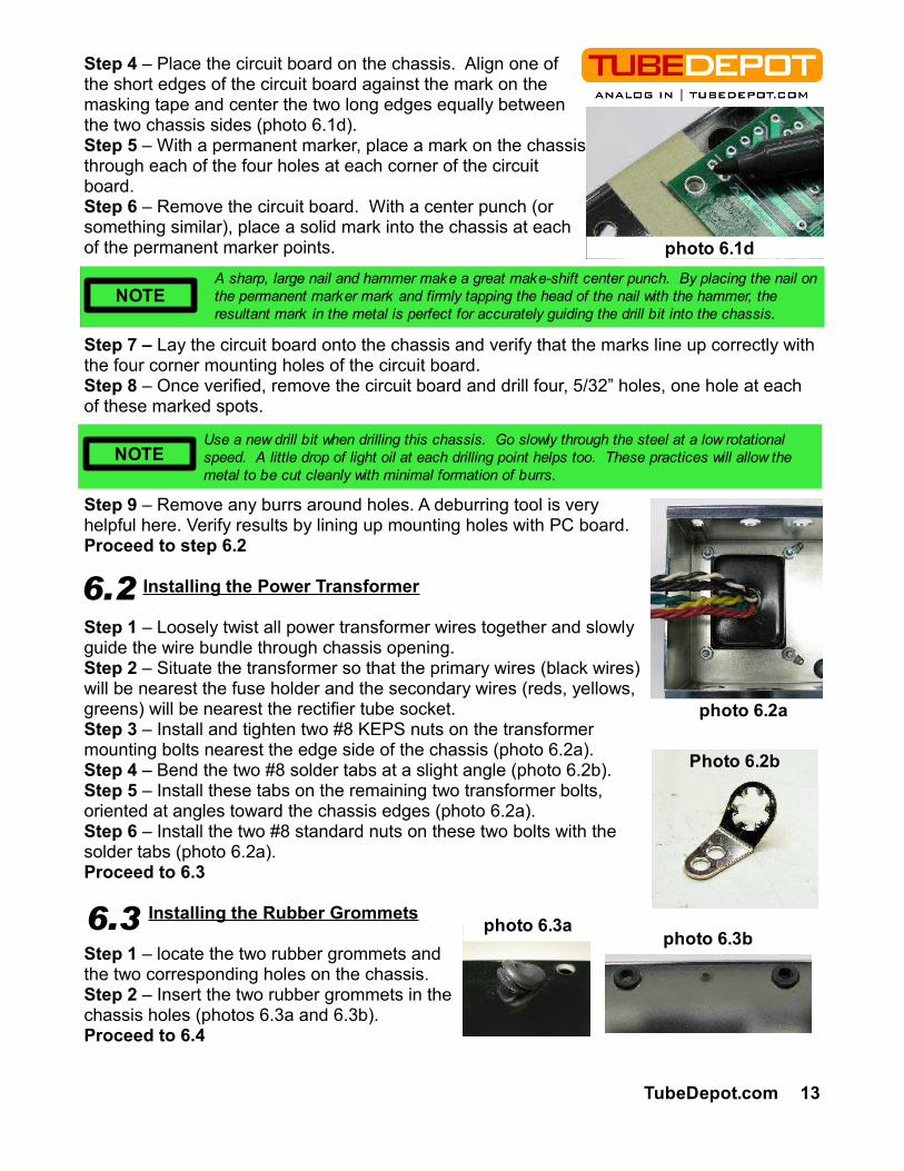
Step 4 – Place the circuit board on the chassis. Align one of the short edges of the circuit board against the mark on the masking tape and center the two long edges equally between the two chassis sides (photo 6.1d).Step 5 – With a permanent marker, place a mark on the chassis through each of the four holes at each corner of the circuit board.Step 6 – Remove the circuit board. With a center punch (or something similar), place a solid mark into the chassis at each of the permanent marker points.
Step 7 – Lay the circuit board onto the chassis and verify that the marks line up correctly with the four corner mounting holes of the circuit board.Step 8 – Once verified, remove the circuit board and drill four, 5/32” holes, one hole at each of these marked spots.
Step 9 – Remove any burrs around holes. A deburring tool is very helpful here. Verify results by lining up mounting holes with PC board.Proceed to step 6.2
Installing the Power Transformer
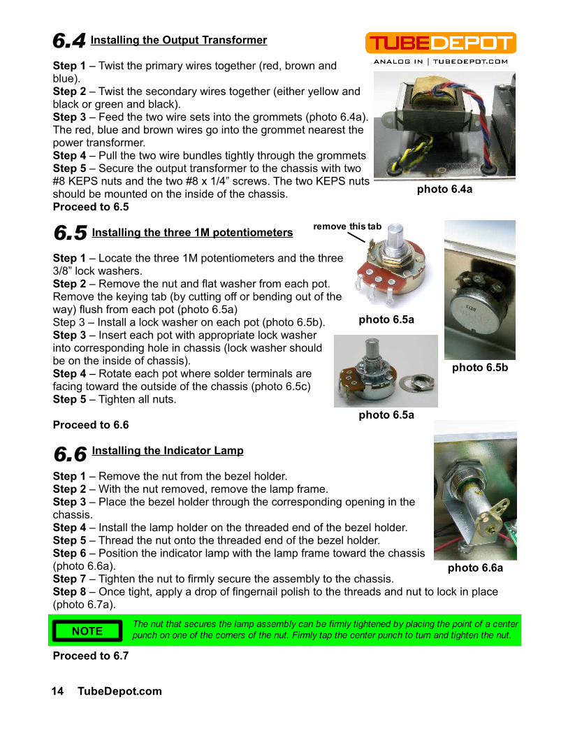
Step 1 – Loosely twist all power transformer wires together and slowly guide the wire bundle through chassis opening.Step 2 – Situate the transformer so that the primary wires (black wires) will be nearest the fuse holder and the secondary wires (reds, yellows, greens) will be nearest the rectifier tube socket.Step 3 – Install and tighten two #8 KEPS nuts on the transformer mounting bolts nearest the edge side of the chassis (photo 6.2a).Step 4 – Bend the two #8 solder tabs at a slight angle (photo 6.2b).Step 5 – Install these tabs on the remaining two transformer bolts, oriented at angles toward the chassis edges (photo 6.2a).Step 6 – Install the two #8 standard nuts on these two bolts with the solder tabs (photo 6.2a).Proceed to 6.3
Installing the Rubber Grommets
Step 1 – locate the two rubber grommets and the two corresponding holes on the chassis.Step 2 – Insert the two rubber grommets in the chassis holes (photos 6.3a and 6.3b).Proceed to 6.4
6.3 photo 6.3a
6.2
TubeDepot.com 13
NOTEA sharp, large nail and hammer make a great make-shift center punch. By placing the nail on the permanent marker mark and firmly tapping the head of the nail with the hammer, the resultant mark in the metal is perfect for accurately guiding the drill bit into the chassis.
NOTEUse a new drill bit when drilling this chassis. Go slowly through the steel at a low rotational speed. A little drop of light oil at each drilling point helps too. These practices will allow the metal to be cut cleanly with minimal formation of burrs.
photo 6.2a
Photo 6.2b
photo 6.3b
photo 6.1d
Installing the Output Transformer
Step 1 – Twist the primary wires together (red, brown and blue).Step 2 – Twist the secondary wires together (either yellow and black or green and black).Step 3 – Feed the two wire sets into the grommets (photo 6.4a). The red, blue and brown wires go into the grommet nearest the power transformer.Step 4 – Pull the two wire bundles tightly through the grommets Step 5 – Secure the output transformer to the chassis with two #8 KEPS nuts and the two #8 x 1/4” screws. The two KEPS nuts should be mounted on the inside of the chassis.Proceed to 6.5
Installing the three 1M potentiometers
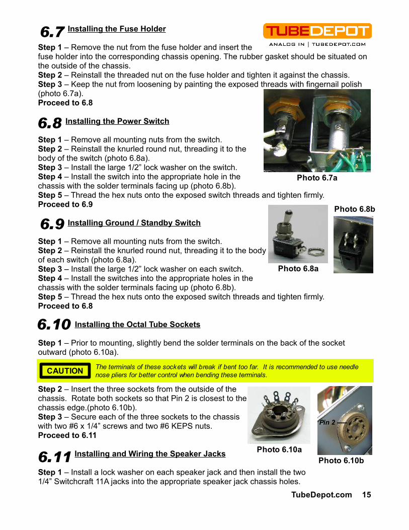
Step 1 – Locate the three 1M potentiometers and the three 3/8” lock washers.Step 2 – Remove the nut and flat washer from each pot. Remove the keying tab (by cutting off or bending out of the way) flush from each pot (photo 6.5a)Step 3 – Install a lock washer on each pot (photo 6.5b).Step 3 – Insert each pot with appropriate lock washer into corresponding hole in chassis (lock washer should be on the inside of chassis).Step 4 – Rotate each pot where solder terminals are facing toward the outside of the chassis (photo 6.5c) Step 5 – Tighten all nuts.
Proceed to 6.6
Installing the Indicator Lamp
Step 1 – Remove the nut from the bezel holder.Step 2 – With the nut removed, remove the lamp frame.Step 3 – Place the bezel holder through the corresponding opening in the chassis.Step 4 – Install the lamp holder on the threaded end of the bezel holder.Step 5 – Thread the nut onto the threaded end of the bezel holder.Step 6 – Position the indicator lamp with the lamp frame toward the chassis (photo 6.6a).Step 7 – Tighten the nut to firmly secure the assembly to the chassis.Step 8 – Once tight, apply a drop of fingernail polish to the threads and nut to lock in place (photo 6.7a).
Proceed to 6.7
6.4
14 TubeDepot.com
6.5
6.6
The nut that secures the lamp assembly can be firmly tightened by placing the point of a center punch on one of the corners of the nut. Firmly tap the center punch to turn and tighten the nut.NOTE
photo 6.4a
photo 6.5a
photo 6.6a
photo 6.5b
photo 6.5a
remove this tab
Installing the Fuse Holder
Step 1 – Remove the nut from the fuse holder and insert the fuse holder into the corresponding chassis opening. The rubber gasket should be situated on the outside of the chassis.Step 2 – Reinstall the threaded nut on the fuse holder and tighten it against the chassis.Step 3 – Keep the nut from loosening by painting the exposed threads with fingernail polish (photo 6.7a).Proceed to 6.8
Installing the Power Switch
Step 1 – Remove all mounting nuts from the switch.Step 2 – Reinstall the knurled round nut, threading it to the body of the switch (photo 6.8a).Step 3 – Install the large 1/2” lock washer on the switch.Step 4 – Install the switch into the appropriate hole in the chassis with the solder terminals facing up (photo 6.8b).Step 5 – Thread the hex nuts onto the exposed switch threads and tighten firmly.Proceed to 6.9
Installing Ground / Standby Switch
Step 1 – Remove all mounting nuts from the switch.Step 2 – Reinstall the knurled round nut, threading it to the body of each switch (photo 6.8a).Step 3 – Install the large 1/2” lock washer on each switch.Step 4 – Install the switches into the appropriate holes in the chassis with the solder terminals facing up (photo 6.8b).Step 5 – Thread the hex nuts onto the exposed switch threads and tighten firmly.Proceed to 6.8
Installing the Octal Tube Sockets
Step 1 – Prior to mounting, slightly bend the solder terminals on the back of the socket outward (photo 6.10a).
Step 2 – Insert the three sockets from the outside of the chassis. Rotate both sockets so that Pin 2 is closest to the chassis edge.(photo 6.10b).Step 3 – Secure each of the three sockets to the chassis with two #6 x 1/4” screws and two #6 KEPS nuts.Proceed to 6.11
Installing and Wiring the Speaker Jacks
Step 1 – Install a lock washer on each speaker jack and then install the two 1/4” Switchcraft 11A jacks into the appropriate speaker jack chassis holes.
The terminals of these sockets will break if bent too far. It is recommended to use needle nose pliers for better control when bending these terminals.CAUTION
Photo 6.10aPhoto 6.10b
6.8
Pin 2 -----
TubeDepot.com 15
Photo 6.8a
Photo 6.8b
6.10
6.11
6.9
Photo 6.7a
6.7
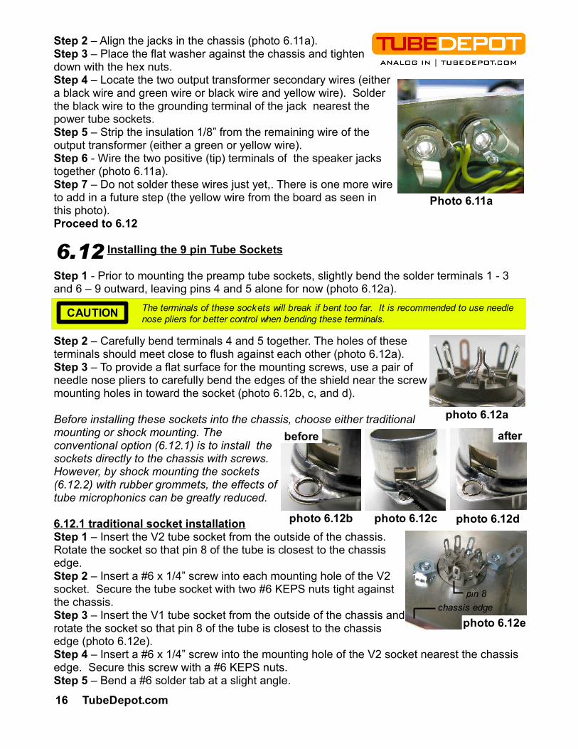
Step 2 – Align the jacks in the chassis (photo 6.11a).Step 3 – Place the flat washer against the chassis and tighten down with the hex nuts.Step 4 – Locate the two output transformer secondary wires (either a black wire and green wire or black wire and yellow wire). Solder the black wire to the grounding terminal of the jack nearest the power tube sockets.Step 5 – Strip the insulation 1/8” from the remaining wire of the output transformer (either a green or yellow wire).Step 6 - Wire the two positive (tip) terminals of the speaker jacks together (photo 6.11a).Step 7 – Do not solder these wires just yet,. There is one more wire to add in a future step (the yellow wire from the board as seen in this photo).Proceed to 6.12
Installing the 9 pin Tube Sockets
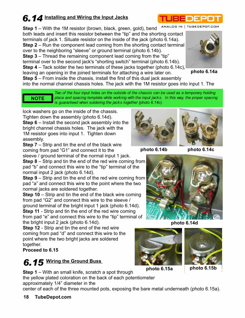
Step 1 - Prior to mounting the preamp tube sockets, slightly bend the solder terminals 1 - 3 and 6 – 9 outward, leaving pins 4 and 5 alone for now (photo 6.12a).
Step 2 – Carefully bend terminals 4 and 5 together. The holes of these terminals should meet close to flush against each other (photo 6.12a).Step 3 – To provide a flat surface for the mounting screws, use a pair of needle nose pliers to carefully bend the edges of the shield near the screw mounting holes in toward the socket (photo 6.12b, c, and d).
Before installing these sockets into the chassis, choose either traditional mounting or shock mounting. The conventional option (6.12.1) is to install the sockets directly to the chassis with screws. However, by shock mounting the sockets (6.12.2) with rubber grommets, the effects of tube microphonics can be greatly reduced.
6.12.1 traditional socket installationStep 1 – Insert the V2 tube socket from the outside of the chassis. Rotate the socket so that pin 8 of the tube is closest to the chassis edge.Step 2 – Insert a #6 x 1/4” screw into each mounting hole of the V2 socket. Secure the tube socket with two #6 KEPS nuts tight against the chassis.Step 3 – Insert the V1 tube socket from the outside of the chassis and rotate the socket so that pin 8 of the tube is closest to the chassis edge (photo 6.12e).Step 4 – Insert a #6 x 1/4” screw into the mounting hole of the V2 socket nearest the chassis edge. Secure this screw with a #6 KEPS nuts.Step 5 – Bend a #6 solder tab at a slight angle.
Photo 6.12a
6.12
chassis edgepin 8
photo 6.12e
Photo 6.11a
16 TubeDepot.com
The terminals of these sockets will break if bent too far. It is recommended to use needle nose pliers for better control when bending these terminals.CAUTION
before after
photo 6.12a
photo 6.12c photo 6.12dphoto 6.12b

Step 6 – Insert a #6 x 1/4” screw into the remaining mounting hole of the V1 socket.Step 7 – Install the #6 solder tab and #6 nut (not a KEPS nut) (photo 6.12e). Tighten firmly.Proceed to 6.13
6.12.2 shock mounted socket installationStep 1 – Determine if you want to shock mount both sockets or just V1.Step 2 – With a 1/4” drill bit (a step bit is excellent for this), enlarge the preamp tube socket mounting holes in the chassis (photo 6.12f). Remove any burrs with a deburring tool.Step 3 – Insert the small grommets in these holes (photo 6.12g) making sure they are properly seated and the hole in the center is clear.Step 4 – Insert the tube socket from the outside of the chassis and rotate the socket so that pin 8 of the tube is closest to the chassis edge. Step 5 – Insert a #6 x 3/8” screw into each mounting hole of the socket. Secure the tube socket with two #6 KEPS nuts, one per screw (photo 6.12g). Seal with fingernail polish as needed.Proceed to 6.13
Installing the Electronics Assembly
Step 1 – Install the four #6 x 1/2” bolts into the drilled mounting holes.Step 2 – With masking tape, tape down the heads of these screws to the chassis to hold them in place (photo 6.13a).Step 3 – Turn chassis over and install the four 1/4” nylon standoffs onto the four #6 x 1/2” bolts.Step 4 – Mount the electronics assembly onto the four #6 X 1/2” bolts and standoffs, each hole of the board corresponding to a bolt. Orientate the board with the filter caps toward the power transformer.
6.13.1 PCB with traditional tube socket installationStep 1 – Apply the four #6 KEPS nuts on the exposed four #6 x 1/2” bolts and tighten them all down finger tight.Step 2 – Remove the masking tape and finish tightening the nuts down to the board.Proceed to 6.14
6.13.2 PCB with shock mounted tube socket installationStep 1 – Install a #6 solder terminal on the board mount nearest the first tube socket, V1 (photo 6.13b).Step 2 – Install a #6 standard nut (not KEPS) on the 1/2” bolt with solder terminal and tighten (photo 6.13b).Step 3 – Install #6 KEPS nuts on the other three #6 screw mounts and tighten.Step 4 – Remove the masking tape and finish tightening the nuts down to the board.Proceed to 6.14
6.13
TubeDepot.com 17
photo 6.13a
Photo 6.12g
photo 6.12f Photo 6.12g
photo 6.13b
Installing and Wiring the Input Jacks
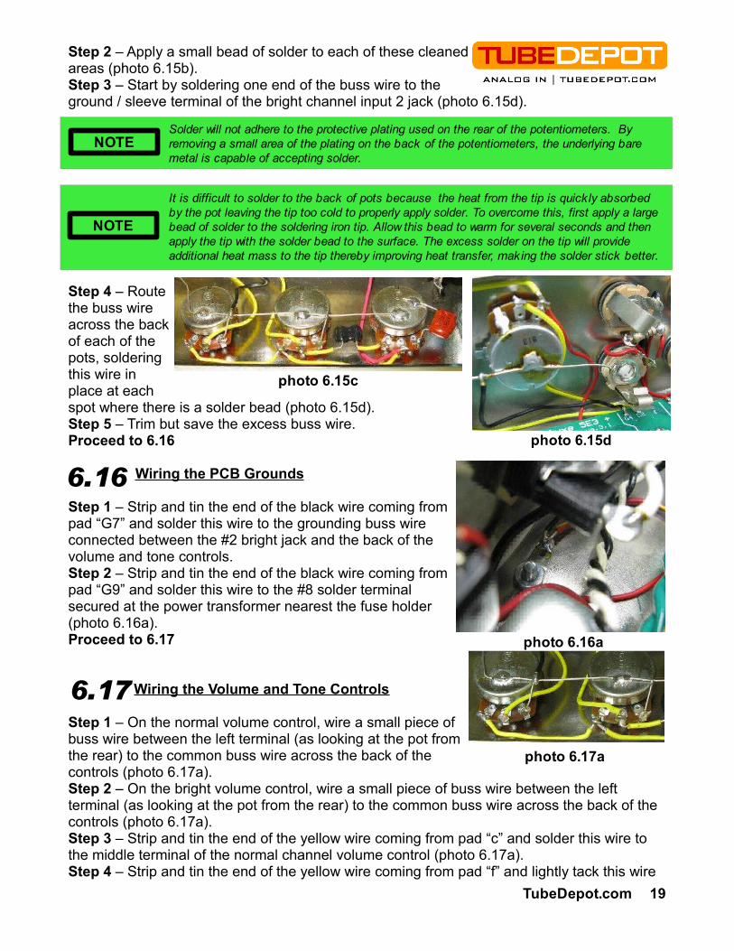
Step 1 – With the 1M resistor (brown, black, green, gold), bend both leads and insert this resistor between the “tip” and the shorting contact terminals of jack 1. Situate resistor on the inside of the jack (photo 6.14a).Step 2 – Run the component lead coming from the shorting contact terminal over to the neighboring “sleeve” or ground terminal (photo 6.14b).Step 3 – Thread the remaining component lead coming from the “tip” terminal over to the second jack's “shorting switch” terminal (photo 6.14b).Step 4 – Tack solder the two terminals of these jacks together (photo 6.14c), leaving an opening in the joined terminals for attaching a wire later on.Step 5 – From inside the chassis, install the first of this dual jack assembly into the normal channel chassis holes. The jack with the 1M resistor goes into input 1. The
lock washers go on the inside of the chassis. Tighten down the assembly (photo 6.14d).Step 6 – Install the second jack assembly into the bright channel chassis holes. The jack with the 1M resistor goes into input 1. Tighten down assembly.Step 7 – Strip and tin the end of the black wire coming from pad “G1” and connect it to the sleeve / ground terminal of the normal input 1 jack.Step 8 – Strip and tin the end of the red wire coming from pad “b” and connect this wire to the “tip” terminal of the normal input 2 jack (photo 6.14d).Step 9 – Strip and tin the end of the red wire coming from pad “a” and connect this wire to the point where the two normal jacks are soldered together. Step 10 – Strip and tin the end of the black wire coming from pad “G2” and connect this wire to the sleeve / ground terminal of the bright input 1 jack (photo 6.14d).Step 11 - Strip and tin the end of the red wire coming from pad “e” and connect this wire to the “tip” terminal of the bright input 2 jack (photo 6.14d).Step 12 - Strip and tin the end of the red wire coming from pad “d” and connect this wire to the point where the two bright jacks are soldered together.Proceed to 6.15
Wiring the Ground Buss
Step 1 – With an small knife, scratch a spot through the yellow plated coloration on the back of each potentiometer approximately 1/4” diameter in the center of each of the three mounted pots, exposing the bare metal underneath (photo 6.15a).
6.14
NOTE
photo 6.14b
Two of the four input holes on the outside of the chassis can be used as a temporary holding place and spacing template while working with the input jacks. In this way, the proper spacing is guaranteed when soldering the jacks together (photo 6.14c).
18 TubeDepot.com
6.15
photo 6.14a
photo 6.15a
photo 6.14d
photo 6.14c
photo 6.15b
Step 2 – Apply a small bead of solder to each of these cleaned areas (photo 6.15b).Step 3 – Start by soldering one end of the buss wire to the ground / sleeve terminal of the bright channel input 2 jack (photo 6.15d).
Step 4 – Route the buss wire across the back of each of the pots, soldering this wire in place at each spot where there is a solder bead (photo 6.15d).Step 5 – Trim but save the excess buss wire.Proceed to 6.16
Wiring the PCB Grounds
Step 1 – Strip and tin the end of the black wire coming from pad “G7” and solder this wire to the grounding buss wire connected between the #2 bright jack and the back of the volume and tone controls.Step 2 – Strip and tin the end of the black wire coming from pad “G9” and solder this wire to the #8 solder terminal secured at the power transformer nearest the fuse holder (photo 6.16a).Proceed to 6.17
Wiring the Volume and Tone Controls
Step 1 – On the normal volume control, wire a small piece of buss wire between the left terminal (as looking at the pot from the rear) to the common buss wire across the back of the controls (photo 6.17a).Step 2 – On the bright volume control, wire a small piece of buss wire between the left terminal (as looking at the pot from the rear) to the common buss wire across the back of the controls (photo 6.17a).Step 3 – Strip and tin the end of the yellow wire coming from pad “c” and solder this wire to the middle terminal of the normal channel volume control (photo 6.17a).Step 4 – Strip and tin the end of the yellow wire coming from pad “f” and lightly tack this wire
6.16
TubeDepot.com 19
6.17
Solder will not adhere to the protective plating used on the rear of the potentiometers. By removing a small area of the plating on the back of the potentiometers, the underlying bare metal is capable of accepting solder.
NOTE
It is difficult to solder to the back of pots because the heat from the tip is quickly absorbed by the pot leaving the tip too cold to properly apply solder. To overcome this, first apply a large bead of solder to the soldering iron tip. Allow this bead to warm for several seconds and then apply the tip with the solder bead to the surface. The excess solder on the tip will provide additional heat mass to the tip thereby improving heat transfer, making the solder stick better.
NOTE
photo 6.17a
photo 6.16a
photo 6.15c
photo 6.15d
in place this wire at the middle terminal of the bright channel volume control (photo 6.17a). Be sure not to fill in the terminal hole with solder just yet.
Step 5 – Route a red wire, 12” in length, behind the electronics assembly PC board, beginning at the tone control and coming out between the preamp tube and the speaker output jack.Step 6 – Strip (but do not tin) the end of the above red wire at the control panel / tone control end and insert the red wire into the middle terminal of the tone control but do not solder just yet (photo 6.17b).Step 7 – Cut two pieces of yellow wire, each 2” long.Step 8 – Strip both ends of each of these two wires but do not tin.Step 9 – Install the first 2” piece by soldering one end to the normal volume control terminal nearest the input jacks (photo 6.17a).Step 10 – Route the other end of this wire to the matching terminal on the bright volume control (photo 6.17a).Step 11 – Install the second 2” piece by inserting one end into the shared outer terminal of the bright volume control and solder these two wires at this terminal.Step 12 – Route the other end of this wire to the shared middle terminal of the tone control and solder the two wires into this terminal.Step 13 – Solder the 500pfd Silver Mica capacitor between the middle terminal of the bright volume control and the right terminal of the tone control (as looking at the pot from the rear) (photo 6.17c).Step 14 – Solder the .0047 ufd capacitor between the left terminal of the tone control (as looking at the pot from the rear) and the back of the tone control pot (photo 6.17c). Proceed to 6.18
Wiring the Rectifier Tube
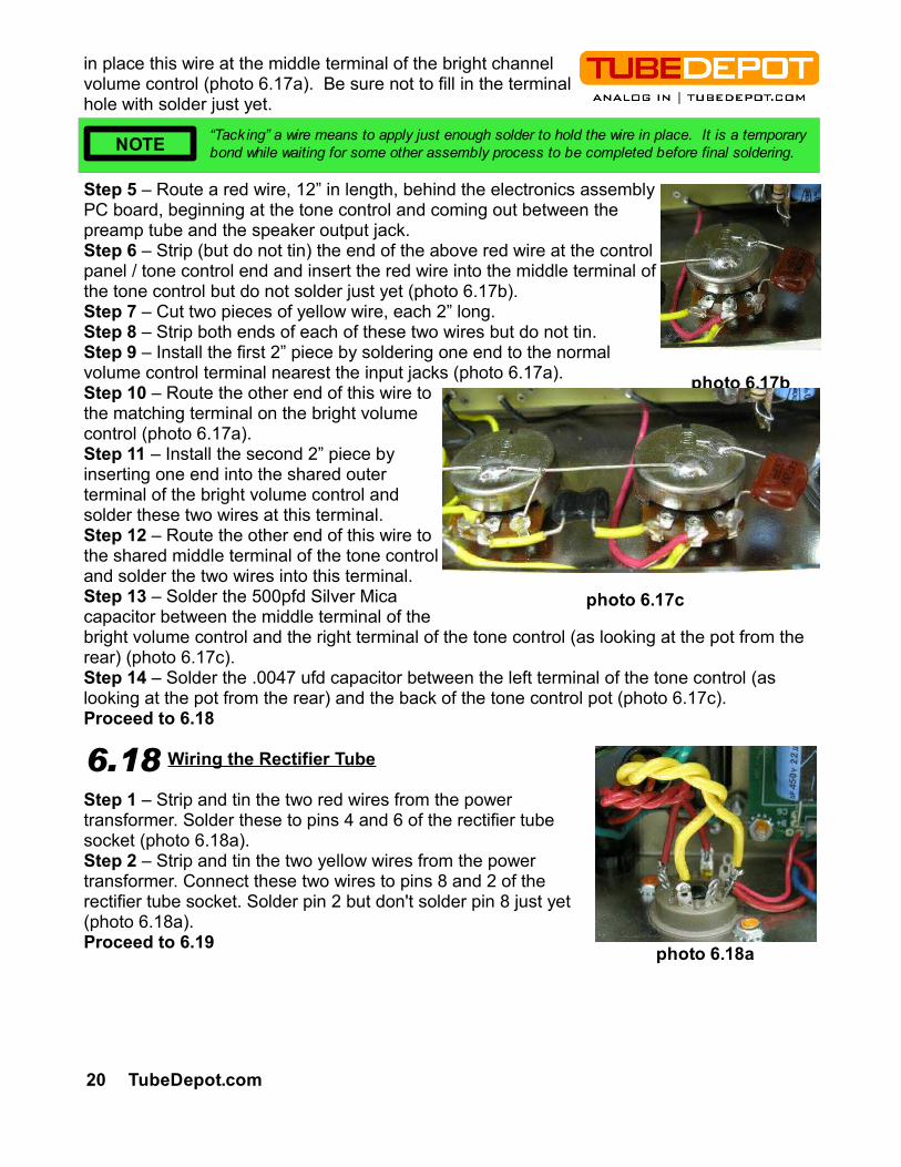
Step 1 – Strip and tin the two red wires from the power transformer. Solder these to pins 4 and 6 of the rectifier tube socket (photo 6.18a).Step 2 – Strip and tin the two yellow wires from the power transformer. Connect these two wires to pins 8 and 2 of the rectifier tube socket. Solder pin 2 but don't solder pin 8 just yet (photo 6.18a).Proceed to 6.19
6.18
“Tacking” a wire means to apply just enough solder to hold the wire in place. It is a temporary bond while waiting for some other assembly process to be completed before final soldering.NOTE
20 TubeDepot.com
photo 6.17b
photo 6.17c
photo 6.18a
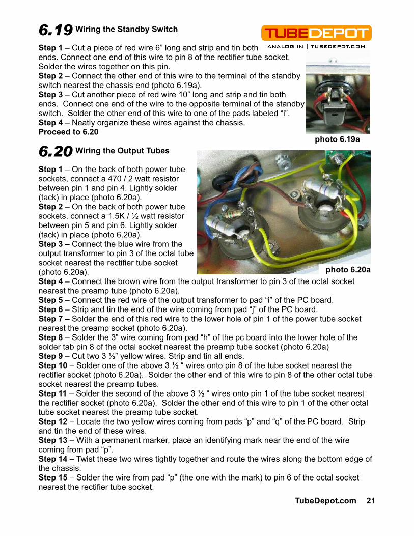
Wiring the Standby Switch
Step 1 – Cut a piece of red wire 6” long and strip and tin both ends. Connect one end of this wire to pin 8 of the rectifier tube socket. Solder the wires together on this pin.Step 2 – Connect the other end of this wire to the terminal of the standby switch nearest the chassis end (photo 6.19a).Step 3 – Cut another piece of red wire 10” long and strip and tin both ends. Connect one end of the wire to the opposite terminal of the standby switch. Solder the other end of this wire to one of the pads labeled “i”.Step 4 – Neatly organize these wires against the chassis.Proceed to 6.20
Wiring the Output Tubes
Step 1 – On the back of both power tube sockets, connect a 470 / 2 watt resistor between pin 1 and pin 4. Lightly solder (tack) in place (photo 6.20a).Step 2 – On the back of both power tube sockets, connect a 1.5K / ½ watt resistor between pin 5 and pin 6. Lightly solder (tack) in place (photo 6.20a).Step 3 – Connect the blue wire from the output transformer to pin 3 of the octal tube socket nearest the rectifier tube socket (photo 6.20a).Step 4 – Connect the brown wire from the output transformer to pin 3 of the octal socket nearest the preamp tube (photo 6.20a).Step 5 – Connect the red wire of the output transformer to pad “i” of the PC board.Step 6 – Strip and tin the end of the wire coming from pad “j” of the PC board.Step 7 – Solder the end of this red wire to the lower hole of pin 1 of the power tube socket nearest the preamp socket (photo 6.20a).Step 8 – Solder the 3” wire coming from pad “h” of the pc board into the lower hole of the solder tab pin 8 of the octal socket nearest the preamp tube socket (photo 6.20a)Step 9 – Cut two 3 ½” yellow wires. Strip and tin all ends.Step 10 – Solder one of the above 3 ½ “ wires onto pin 8 of the tube socket nearest the rectifier socket (photo 6.20a). Solder the other end of this wire to pin 8 of the other octal tube socket nearest the preamp tubes.Step 11 – Solder the second of the above 3 ½ “ wires onto pin 1 of the tube socket nearest the rectifier socket (photo 6.20a). Solder the other end of this wire to pin 1 of the other octal tube socket nearest the preamp tube socket.Step 12 – Locate the two yellow wires coming from pads “p” and “q” of the PC board. Strip and tin the end of these wires.Step 13 – With a permanent marker, place an identifying mark near the end of the wire coming from pad “p”.Step 14 – Twist these two wires tightly together and route the wires along the bottom edge of the chassis.Step 15 – Solder the wire from pad “p” (the one with the mark) to pin 6 of the octal socket nearest the rectifier tube socket.
6.20
TubeDepot.com 21
6.19
photo 6.20a
photo 6.19a
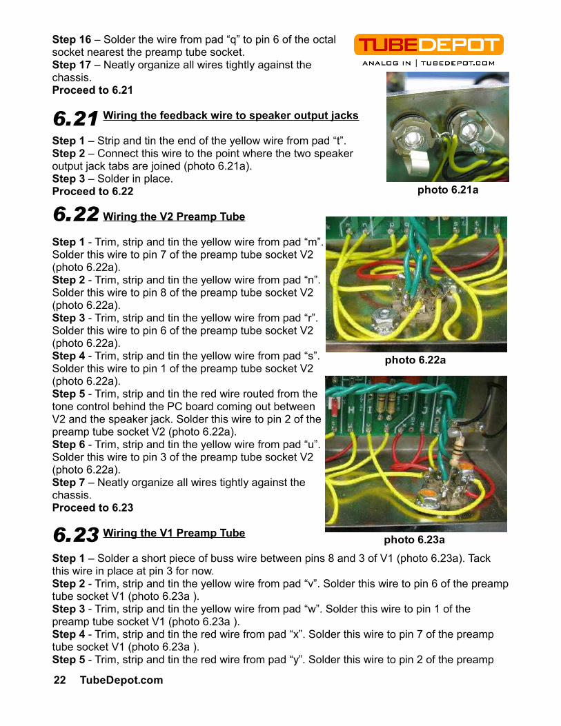
Step 16 – Solder the wire from pad “q” to pin 6 of the octal socket nearest the preamp tube socket.Step 17 – Neatly organize all wires tightly against the chassis.Proceed to 6.21
Wiring the feedback wire to speaker output jacks
Step 1 – Strip and tin the end of the yellow wire from pad “t”.Step 2 – Connect this wire to the point where the two speaker output jack tabs are joined (photo 6.21a).Step 3 – Solder in place.Proceed to 6.22
Wiring the V2 Preamp Tube
Step 1 - Trim, strip and tin the yellow wire from pad “m”. Solder this wire to pin 7 of the preamp tube socket V2 (photo 6.22a).Step 2 - Trim, strip and tin the yellow wire from pad “n”. Solder this wire to pin 8 of the preamp tube socket V2 (photo 6.22a).Step 3 - Trim, strip and tin the yellow wire from pad “r”. Solder this wire to pin 6 of the preamp tube socket V2 (photo 6.22a).Step 4 - Trim, strip and tin the yellow wire from pad “s”. Solder this wire to pin 1 of the preamp tube socket V2 (photo 6.22a).Step 5 - Trim, strip and tin the red wire routed from the tone control behind the PC board coming out between V2 and the speaker jack. Solder this wire to pin 2 of the preamp tube socket V2 (photo 6.22a).Step 6 - Trim, strip and tin the yellow wire from pad “u”. Solder this wire to pin 3 of the preamp tube socket V2 (photo 6.22a).Step 7 – Neatly organize all wires tightly against the chassis.Proceed to 6.23
Wiring the V1 Preamp Tube
Step 1 – Solder a short piece of buss wire between pins 8 and 3 of V1 (photo 6.23a). Tack this wire in place at pin 3 for now.Step 2 - Trim, strip and tin the yellow wire from pad “v”. Solder this wire to pin 6 of the preamp tube socket V1 (photo 6.23a ).Step 3 - Trim, strip and tin the yellow wire from pad “w”. Solder this wire to pin 1 of the preamp tube socket V1 (photo 6.23a ).Step 4 - Trim, strip and tin the red wire from pad “x”. Solder this wire to pin 7 of the preamp tube socket V1 (photo 6.23a ).Step 5 - Trim, strip and tin the red wire from pad “y”. Solder this wire to pin 2 of the preamp
6.22
22 TubeDepot.com
6.23
photo 6.22a
photo 6.23a
6.21
photo 6.21a
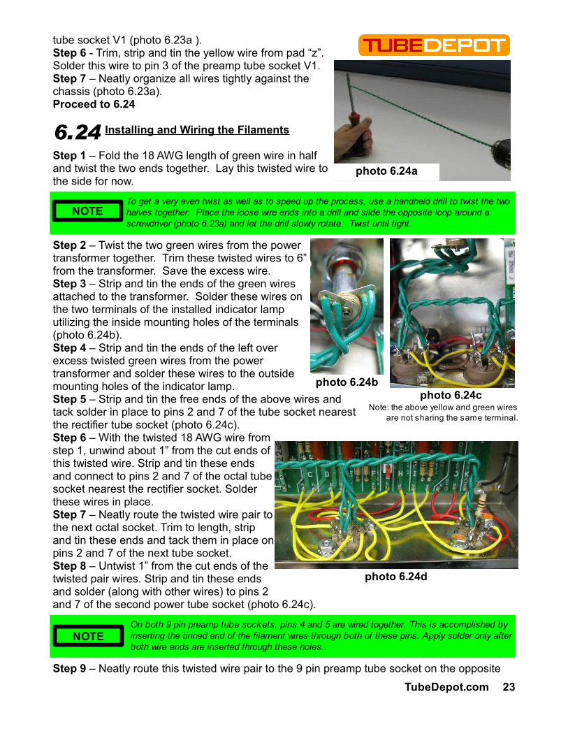
tube socket V1 (photo 6.23a ).Step 6 - Trim, strip and tin the yellow wire from pad “z”. Solder this wire to pin 3 of the preamp tube socket V1.Step 7 – Neatly organize all wires tightly against the chassis (photo 6.23a).Proceed to 6.24
Installing and Wiring the Filaments
Step 1 – Fold the 18 AWG length of green wire in half and twist the two ends together. Lay this twisted wire to the side for now.
Step 2 – Twist the two green wires from the power transformer together. Trim these twisted wires to 6” from the transformer. Save the excess wire.Step 3 – Strip and tin the ends of the green wires attached to the transformer. Solder these wires on the two terminals of the installed indicator lamp utilizing the inside mounting holes of the terminals (photo 6.24b).Step 4 – Strip and tin the ends of the left over excess twisted green wires from the power transformer and solder these wires to the outside mounting holes of the indicator lamp.Step 5 – Strip and tin the free ends of the above wires and tack solder in place to pins 2 and 7 of the tube socket nearest the rectifier tube socket (photo 6.24c). Step 6 – With the twisted 18 AWG wire from step 1, unwind about 1” from the cut ends of this twisted wire. Strip and tin these ends and connect to pins 2 and 7 of the octal tube socket nearest the rectifier socket. Solder these wires in place.Step 7 – Neatly route the twisted wire pair to the next octal socket. Trim to length, strip and tin these ends and tack them in place on pins 2 and 7 of the next tube socket.Step 8 – Untwist 1” from the cut ends of the twisted pair wires. Strip and tin these ends and solder (along with other wires) to pins 2 and 7 of the second power tube socket (photo 6.24c).
Step 9 – Neatly route this twisted wire pair to the 9 pin preamp tube socket on the opposite
6.24
TubeDepot.com 23
NOTETo get a very even twist as well as to speed up the process, use a handheld drill to twist the two halves together. Place the loose wire ends into a drill and slide the opposite loop around a screwdriver (photo 6.23a) and let the drill slowly rotate. Twist until tight.
photo 6.24cphoto 6.24b
On both 9 pin preamp tube sockets, pins 4 and 5 are wired together. This is accomplished by inserting the tinned end of the filament wires through both of these pins. Apply solder only after both wire ends are inserted through these holes.
NOTE
photo 6.24d
photo 6.24a
Note: the above yellow and green wires are not sharing the same terminal.
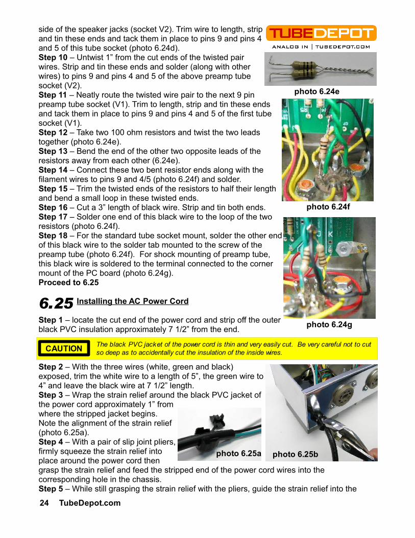
side of the speaker jacks (socket V2). Trim wire to length, strip and tin these ends and tack them in place to pins 9 and pins 4 and 5 of this tube socket (photo 6.24d).Step 10 – Untwist 1” from the cut ends of the twisted pair wires. Strip and tin these ends and solder (along with other wires) to pins 9 and pins 4 and 5 of the above preamp tube socket (V2).Step 11 – Neatly route the twisted wire pair to the next 9 pin preamp tube socket (V1). Trim to length, strip and tin these ends and tack them in place to pins 9 and pins 4 and 5 of the first tube socket (V1).Step 12 – Take two 100 ohm resistors and twist the two leads together (photo 6.24e).Step 13 – Bend the end of the other two opposite leads of the resistors away from each other (6.24e).Step 14 – Connect these two bent resistor ends along with the filament wires to pins 9 and 4/5 (photo 6.24f) and solder.Step 15 – Trim the twisted ends of the resistors to half their length and bend a small loop in these twisted ends.Step 16 – Cut a 3” length of black wire. Strip and tin both ends.Step 17 – Solder one end of this black wire to the loop of the two resistors (photo 6.24f).Step 18 – For the standard tube socket mount, solder the other end of this black wire to the solder tab mounted to the screw of the preamp tube (photo 6.24f). For shock mounting of preamp tube, this black wire is soldered to the terminal connected to the corner mount of the PC board (photo 6.24g).Proceed to 6.25
Installing the AC Power Cord
Step 1 – locate the cut end of the power cord and strip off the outer black PVC insulation approximately 7 1/2” from the end.
Step 2 – With the three wires (white, green and black) exposed, trim the white wire to a length of 5”, the green wire to 4” and leave the black wire at 7 1/2” length.Step 3 – Wrap the strain relief around the black PVC jacket of the power cord approximately 1” from where the stripped jacket begins. Note the alignment of the strain relief (photo 6.25a).Step 4 – With a pair of slip joint pliers, firmly squeeze the strain relief into place around the power cord then grasp the strain relief and feed the stripped end of the power cord wires into the corresponding hole in the chassis.Step 5 – While still grasping the strain relief with the pliers, guide the strain relief into the
24 TubeDepot.com
The black PVC jacket of the power cord is thin and very easily cut. Be very careful not to cut so deep as to accidentally cut the insulation of the inside wires.CAUTION
6.25
photo 6.25b
photo 6.24e
photo 6.24f
photo 6.24g
photo 6.25a

chassis hole. By firmly pressing the compressed strain relief into the hole, the strain relief should slide into place (photo 6.25b).
Step 6 – Once the strain relief is installed, pull on the power cord to verify that it is indeed firmly mounted. Proceed to 6.26
Wiring the AC Power Cord Ground
Step 1 – Loosely route the green wire from the AC cord to the #8 solder terminal nearest the rectifier tube socket (photo 6.26a).Step 2 – Trim to length. Strip and tin the end of the remaining green wire of the AC power cord.Step 3 – Solder this green wire to the #8 solder terminal nearest the rectifier tube socket.Proceed to 6.27
Wiring Power Transformer Center Tap
Step 1 – Locate and untwist the red wire with yellow stripe from the wire bundle coming from the power transformer.Step 2 – Loosely route this wire from the transformer to the #8 solder terminal located nearest the rectifier tube socket.Step 3 – Trim to length. Strip and tin the end of this red wire with yellow stripe coming from the power transformer.Step 4 – Connect this wire to the shared #8 solder terminal nearest the tube rectifier and solder wires to this terminal (photo 6.27a).Proceed to 6.28
Wiring the Fuse Holder
Step 1 – Wire the “HOT” of the AC mains power cord (black wire in the USA) to the end terminal of the fuse holder (video and photos show incorrect white wire here).Step 2 – Cut a 5” piece of 18awg black wire. Strip and tin each end.Step 3 – Solder one end of this wire to the remaining solder terminal of the fuse holder.Proceed to 6.29
Wiring the Power Switch
Step 1 – Solder the other end of the above black wire coming from the fuse holder to the left terminal of the power switch.Step 2 – Locate the power transformer's black wire and solder it to the remaining solder terminal of the power switch (see layout for visual description).Proceed to 6.30
TubeDepot.com 25
By wiring the fuse holder as recommended, shock hazards associated with changing a fuse are reduced because the source AC is at the far end of the fuse holder and not at the cap end. WARNING
6.28
There is a specific tool that makes installing strain reliefs simple. If you find yourself installing strain reliefs on a regular basis, this tool is worth owning. See TubeDepot.com p/n TL-R-29NOTE
Photo 6.26a
6.26
6.27
Photo 6.27a
6.29
Wiring the Power Transformer
Step 1 – Locate the power transformer's appropriate primary wire for your AC mains voltage (white wire for USA). See the below table for choosing the correct wire for your location. Strip and tin the end of this wire.Step 2 – Strip and tin the end of the “NEUTRAL” wire of the AC power cord (white wire in the USA).Step 3 – Twist the ends of the above wires together and solder. Cap the end of these twisted wires with either a wire nut or heat shrink (preferred). Make sure that no bare wire is showing.
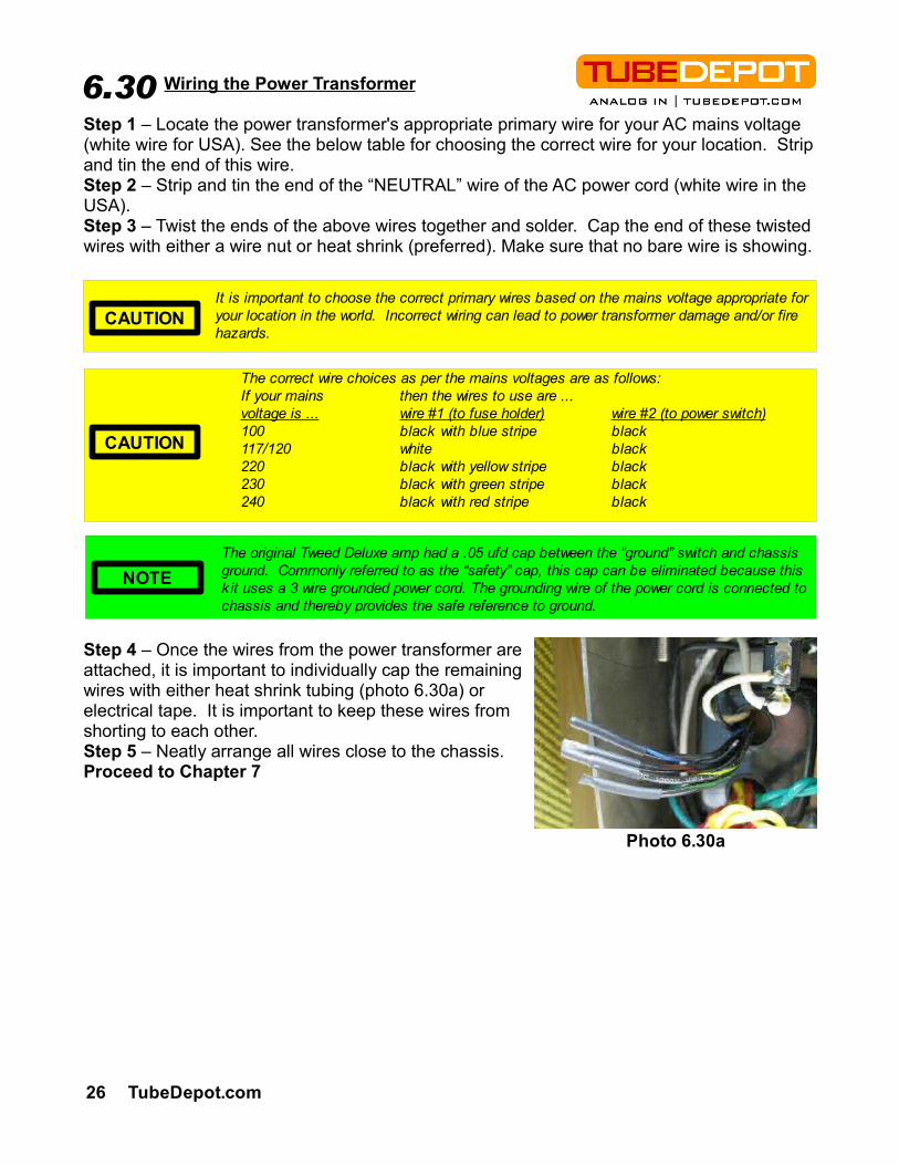
Step 4 – Once the wires from the power transformer are attached, it is important to individually cap the remaining wires with either heat shrink tubing (photo 6.30a) or electrical tape. It is important to keep these wires from shorting to each other.Step 5 – Neatly arrange all wires close to the chassis.Proceed to Chapter 7
26 TubeDepot.com
It is important to choose the correct primary wires based on the mains voltage appropriate for your location in the world. Incorrect wiring can lead to power transformer damage and/or fire hazards.
CAUTION
The correct wire choices as per the mains voltages are as follows:If your mains then the wires to use are ...voltage is ... wire #1 (to fuse holder) wire #2 (to power switch)100 black with blue stripe black117/120 white black220 black with yellow stripe black230 black with green stripe black240 black with red stripe black
CAUTION
The original Tweed Deluxe amp had a .05 ufd cap between the “ground” switch and chassis ground. Commonly referred to as the “safety” cap, this cap can be eliminated because this k it uses a 3 wire grounded power cord. The grounding wire of the power cord is connected to chassis and thereby provides the safe reference to ground.
NOTE
Photo 6.30a
6.30
Installing the Chassis Mounting Bolts and Chassis
Step 1 – Press the two truss bolts into the cabinet holes (if not already installed).Step 2 – Place the amp on the floor onto it's front with the speaker magnet facing up.Step 3 – Mount the chassis onto the truss bolts, sliding the chassis against the cabinet top.Step 4 – Install the two #10 KEPS nuts, one on each bolt, and finger tighten the chassis against top of cabinet.Step 5 – Pick the face of the amp off of the floor and stand amp up right.Step 6 – With the nuts on loosely, slide the chassis to the rear of cabinet, away from speaker.Step 7 – Press back panel into position, pushing the chassis against the panel. This will properly align the chassis with in the cabinet and provide good contact with the shielding foil.
Step 8 – Place the back panel to the side and firmly tighten chassis into the cabinet. Do not install back panel just yet.Proceed to 7.2
Installing AC Power Cord Clamp
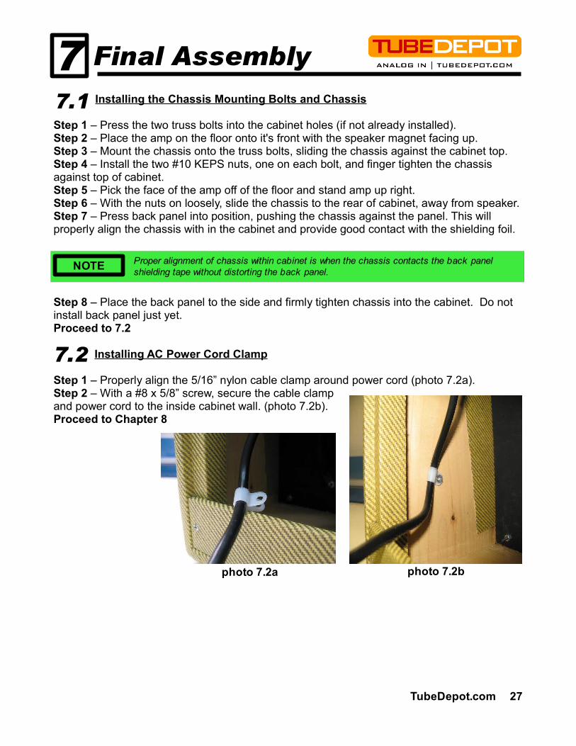
Step 1 – Properly align the 5/16” nylon cable clamp around power cord (photo 7.2a).Step 2 – With a #8 x 5/8” screw, secure the cable clamp and power cord to the inside cabinet wall. (photo 7.2b).Proceed to Chapter 8
Proper alignment of chassis within cabinet is when the chassis contacts the back panel shielding tape without distorting the back panel.NOTE
photo 7.2bphoto 7.2a
7.1
7.2
7 Final Assembly
TubeDepot.com 27
You are almost finished. And although the first temptation is to plug up the amp and turn it on, I want to caution you to instead take the time and review all your
connections. This will be time well spent as it ties together all the construction steps. Any errors are more likely to stand during this time. It is not uncommon to find two or three errors. After verifying all of the above connections are correct, read through all of the following steps before completing any of them. Once you have finished reading these steps, it is time to begin. All of the following voltages are measured with full 120VAC wall voltage applied.
Step 1 - Install a 2A, fast blow fuse into the fuse holder and a lamp in the lamp holder.
Step 2 – With the amp unplugged and no tubes installed, turn on the amplifier's power and standby switch (or in this case the “ground” switch, turned toward the word “ground” on the chassis).. The power and standby switches will remain on until all tests are finished.Step 3 – Plug the amp's AC power cord into AC power at the wall.
Step 4 – The panel indicator should illuminate. Monitor for any unusually smoke or smells or a blown fuse or hot power transformer. If anything unusual occurs, disconnect power immediately and review connections.Step 5 – If there is nothing unusual after a couple of minutes, remove AC power by disconnecting the AC power cord from the AC source. Leaving the amp's power switch “on”.Step 6 – With the amp still disconnected from AC power, install the tube rectifier.Step 7 – Plug the amplifier's AC power cord into the AC power source at the wall.Step 8 – The panel indicator should illuminate. Visually verify that the filament inside the rectifier tube is glowing. Monitor the amplifier for any unusual smoke or smells or blown fuse. If anything unusual occurs, disconnect power immediately and review connections.
It is good practice to use a power strip with a circuit breaker and an on/off switch between the wall power and the amplifier power cord as an improved electrical safety measure.CAUTION
In case of any troubles, quickly disconnecting the power cord from the wall (or turn off the power strip). You should not touch the amp or the amp's power switch until the amplifier's power cord is no longer connected to AC wall power.
WARNING
CAUTION Use of any fuse larger than 2A is not recommended and could cause severe and costly equipment damage in case of an internal component failure.
Within a minute or two, the rectifier will have heated up and provided a slowly increasing high voltage to the power supply. This voltage will properly form the high voltage filter caps.NOTE
I personally recommend using a variable AC with separate current and voltage meters. This allows bringing the voltages up very slowly and provides more accurate monitoring capabilities.NOTE
If you are uncomfortable with just turning on the amp and watching for smoke, I recommend building an inexpensive Dim-Bulb tester to monitor and control current flow into the amp. A quick internet search on “Dim Bulb tester” will give several diagrams and plans.
NOTE
When changing or installing a fuse or lamp, always remove the AC source by unplugging the amp. Never use fingers to remove or insert a fuse into a fuse holder. Instead, use the fuse cap to hold the fuse when removing or inserting into the holder.
WARNING
8.1
28 TubeDepot.com
Testing8
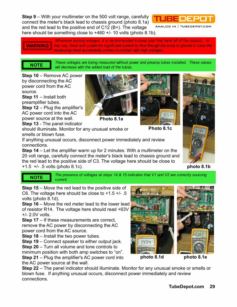
Step 9 – With your multimeter on the 500 volt range, carefully connect the meter's black lead to chassis ground (photo 8.1a) and the red lead to the positive end of C12 (B+). The voltage here should be something close to +460 +/- 10 volts (photo 8.1b).
Step 10 – Remove AC power by disconnecting the AC power cord from the AC source.Step 11 – Install both preamplifier tubes.Step 12 – Plug the amplifier's AC power cord into the AC power source at the wall.Step 13 - The panel indicator should illuminate. Monitor for any unusual smoke or smells or blown fuse.If anything unusual occurs, disconnect power immediately and review connections.Step 14 – Let the amplifier warm up for 2 minutes. With a multimeter on the 20 volt range, carefully connect the meter's black lead to chassis ground and the red lead to the positive side of C3. The voltage here should be close to +1.5 +/- .5 volts (photo 8.1c).
Step 15 – Move the red lead to the positive side of C6. The voltage here should be close to +1.5 +/- .5 volts (photo 8.1d).Step 16 – Move the red meter lead to the lower lead of resistor R14. The voltage here should read +63V +/- 2.0V volts.Step 17 – If these measurements are correct, remove the AC power by disconnecting the AC power cord from the AC source.Step 18 – Install the two power tubes.Step 19 – Connect speaker to either output jack.Step 20 – Turn all volume and tone controls to minimum position with both amp switches to “on”.Step 21 – Plug the amplifier's AC power cord into the AC power source at the wall.Step 22 – The panel indicator should illuminate. Monitor for any unusual smoke or smells or blown fuse. If anything unusual occurs, disconnect power immediately and review connections.
Whenever testing voltages, it is recommended to keep your free hand off of the chassis. In this way, there isn't a path for significant current to flow through the body to ground in case the measuring hand accidentally comes in contact with high voltages.
WARNING
The presence of voltages at steps 14 & 15 indicates that V1 and V2 are correctly sourcing current.NOTE
Photo 8.1c
TubeDepot.com 29
These voltages are being measured without power and preamp tubes installed. These values will decrease with the added load of the tubes.NOTE
photo 8.1b
Photo 8.1a
photo 8.1d photo 8.1e

Step 23 – Let the amplifier warm for 2 minutes.With a multimeter on the 200 volt range, carefully connect the meter's black lead to chassis ground and the red lead to the positive side of C10. The voltage here should read close to +22 +/- 3 volts (photo 8.1e).
Step 24 – If all the above measurements are within specifications, and the speaker is connected, and with no signal source connected to either input, turn up the volume control and listen for a low level hiss from the speaker. There will be a slight hum, but anything drastic indicates wiring troubles.Step 25 – If the above hiss is heard, turn the volume control back to minimum and connect a signal source into input 1 of the bright channel.
Step 26 – Turn up the volume on the amp and the signal source (most likely a guitar or harmonica microphone) and verify that the signal is coming from the speaker.Step 27 – If everything checks good, turn off amp and install the back panel.Step 28 – Now the time has come to rock out … your amp is done!
END
Congratulations! Please send me a photos of your finished amp. A couple photos of the insides of your amp, maybe a couple photos of your work bench and of course a few photos of the amp being played by you, all of these would be greatly appreciated. Send them to me at the below address.
TubeDepot.comc/o Robert Hull1686 Barcrest Dr.Memphis, TN 38134
… or to my email:
Keep on playing …
A signal source can be a guitar or high impedance microphone or even a low level CD or MP3 player. A speaker output from another amp is not recommended.NOTE
The presence of voltage at step 22 indicates that V3 and V4 are correctly sourcing current.
NOTE
30 TubeDepot.com

M
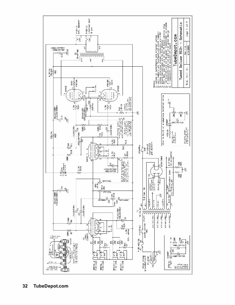
Schematics9
TubeDepot.com 31
Schematic next page
32 TubeDepot.com
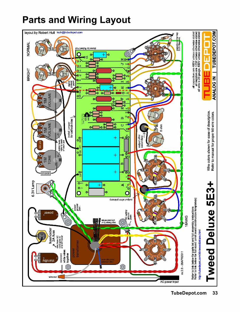
Parts and Wiring Layout
TubeDepot.com 33

Once you have the amp working and sounding good, here are a few ideas to “shape” the tone to suite your tastes.
1. Change both C1 and C2 from .1ufd to .047ufd or .022ufd or .01ufd or even .0047ufd! Make sure to change both equally. This mod will reduce low frequency response (muddiness) at high gain settings, giving the amp the ability to “cut through”.
2. Change both C8 and C9 like above. This modification will provide similar results to the above mod but since this modification appears after the phase inverter, there will be a different tonal response. Experiment with small changes to both stages vs. one large change per each stage.
3. Install 33ufd/500v or 47ufd/500v caps in C12 and C13 positions - tightens power supply and provides quicker dynamics.
4. Experiment with value of R9. Install a 1.5K resistor for better definition and controlled gain when using a 12AX7 as input tube.
5. Experiment with the value of C3 and C6. By decreasing the values from 22ufd to 10ufd all the way to 1ufd or .47ufd, the gain response of these two stages can be shaped to have reduced muddy low end gain and better defined mids and highs.
6. Pin 8 and pin 3 share a cathode bypass resistor and capacitor. By separating pin 3 and pin 8 from V1 and assigning each their own cathode circuit, additional tone shaping can be achieved (a la Marshall). Start by soldering pin 8 to the C3 / R9 circuit on the PC board. Solder the now empty pin 3 of V1 to a separate capacitor and resistor pair. Good values to choose would be 2.7K ohms for the resistor and .68 ufd for the capacitor. This gives a tight midrange response without being too bright.
7. Change out 6V6 tubes for EL84 tubes by fabricating your own cover plate adapter and installing a 9 pin tube socket – allows installing EL84s vs. 6V6. I would encourage retaining the tube rectifier when applying this modification for great “sag”.
8. Change out 6V6 with 5881. This is a great spongy tube that responds extremely well when pushed hard. Because the 5881 consumes twice the filament current as compared to the 6V6, it is recommended to use a solid state rectifier in place of the tube rectifier when using 5881 tubes. By not using the tube rectifier, there is additional power transformer over head. This overhead is needed for the increased filament requirements of the 5881. The filter caps must be upgraded to +500V.
9. Install solid state rectifier in place of tube rectifier – tightens up dynamics and power output. Filter caps MUST be upgraded to +500V types. Additionally, the 6V6 tubes must be very good quality to withstand the higher plate voltages.
10.Run amp without negative feedback altogether by disconnecting feedback line from speaker output jack – provides more overall gain and distortion with the amp volume at “12”. Similar to setting the feedback adjustment fully counterclockwise.
11. Build an external speaker load box to lower the wattage going to the speaker. Great for recording. And it only requires 2 resistors for the basic box (see Appendix E).
12.Wire the amp for fixed bias vs. the original cathode bias to get more power and dynamics out of the amp. The transformers will run slightly cooler as well.
10 Cool Modifications
34 TubeDepot.com

Resistor and Capacitor Codes This project uses different types of resistors and capacitors. The diagrams below will assist you in locating and identifying values, tolerances and ratings for the various circuit requirements for your project.
Resistor Power Ratings
Not only are resistors graded by their values but also by their power ratings. Power ratings are determined by how much heat (power) can be safely dissipated by the resistor. Higher ratings are usually indicated by larger sizes.
Below are photos and descriptions of various resistors that could be used in this project.
Carbon Composition 1/2W
Carbon Film 1/2W
Metalized Film 1/2W
Carbon Composition 1W
Metal Oxide 1W
Metal Oxide 2W
Metal Oxide 3W
A Appendix A
TubeDepot.com 35
Wire Wound 5W
Wire Wound 8W
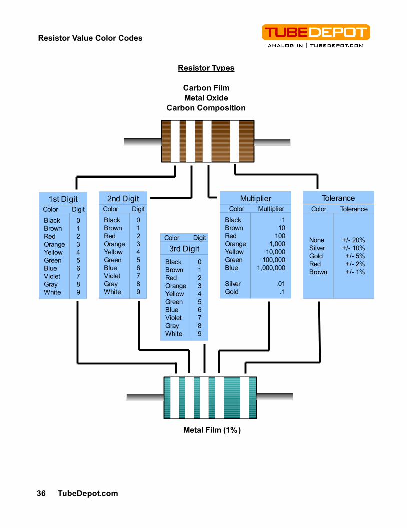
Resistor Value Color Codes
36 TubeDepot.com
1st Digit
BlackBrownRedOrangeYellowGreenBlueVioletGrayWhite
0123456789
2nd Digit Color Digit Color Digit
BlackBrownRedOrangeYellowGreenBlueVioletGrayWhite
0123456789
Multiplier Color Multiplier
BlackBrownRedOrangeYellowGreenBlue
SilverGold
110
1001,000
10,000100,000
1,000,000
.01.1
Tolerance Color Tolerance
NoneSilverGoldRedBrown
+/- 20%+/- 10%+/- 5%+/- 2%+/- 1%
3rd Digit Color Digit
BlackBrownRedOrangeYellowGreenBlueVioletGrayWhite
0123456789
Metal Film (1%)
Resistor Types
Carbon FilmMetal Oxide
Carbon Composition

How to Read Capacitor Value Codes
This project uses several different kinds of capacitors. Some of these capacitors have their values and voltage ratings printed on them, others use numerical codes. The diagrams below will assist you in locating and identifying capacitor values, tolerances, and voltage ratings for the various circuit requirements for your project.
Sprague “Orange Drop” 715 series – Vintage style film & foil polypropylene capacitor.
1st line: 715P600V = 715 series; rated at 600V2nd line: 104J 0821 = value in pfd (104 = 10 and 4 zeros pfd);
tolerance (J = +/- 5%); batch code104 = .1ufd103 = .01ufd 223 = .022ufd 473 = .047ufd102 = .001ufd 222 = .0022ufd 472 = .0047ufd
Cornell-Dubilier Silver Mica – high quality / high accuracy picofarad cap
1st line: 250 +/- %5 = direct value in pfd (250pfd); tolerance 5%2nd line: 500V SM = voltage rating (500V); batch code
Xicon Metalized Polypropylene – Warm tone, small size
1st line: F104K d = value in pfd (104 = 10 and 4 zeros pfd); tolerance (K = +/- 10%)
2nd line: 630MPP 1 = voltage rating (630V); construction (MPP = metalized polypropylene)
104 = .1ufd103 = .01ufd 223 = .022ufd 473 = .047ufd102 = .001ufd 222 = .0022ufd 472 = .0047ufd
Sozo and Mallory 150 Film and Foil – Vintage style film & foil polypropylene capacitor, axial leads
1st line: 684K = value in pfd (684 = 68 and 4 zeros pfd); tolerance (K = +/- 10%)
2nd line: 160V = voltage rating (160V)3rd line: 0834R = batch / date code
104 = .1ufd 684 = .68ufd103 = .01ufd 223 = .022ufd 473 = .047ufd102 = .001ufd 222 = .0022ufd 472 = .0047ufd
TubeDepot.com 37

Soldering Hints Anyone working in electronics should learn how to solder well. Thankfully it isn't hard, it just takes practice and having the proper tools. Once you are able to solder well, your projects will be more professional and more reliable.
Refer to our video “How To Solder” for detailed explanations.http://www.youtube.com/watch?v=cIDydYIVTqU&feature=channel_page
But before you get started, here are a few safety tips that should be followed:
– Fumes from soldering can be harmful therefore it is important to always have adequate ventilation.
– Wear appropriate clothing when working around hot, molten solder. Never wear shorts or open toes shoes.
– protect hands and equipment from burns by using a soldering iron holder. An improperly stored soldering iron is a fire hazard
– Do not eat, drink, or smoke while you are soldering. Limit exposure to lead.– Wash hands often when soldering.– Wear safety glasses when soldering.
Purpose of Soldering Soldering is used to bond two or more metals together. By applying heat to a connection and feeding solder into this connection, the solder will melt and flow around the metals. A small surface amount of each of the metals will additionally melt and inter-mix with the liquid solder forming an alloy. This connection is called an intermetallic bond and the two metals, when properly soldered together, act as if it they were one solid piece.
Importance of Proper Soldering Proper soldering is the basis for faithful equipment operation. A good solder connection is physically strong and electrically reliable. A poorly soldered connection will have intermittent operation which can cause electrical damage to neighboring components. At the very least, a bad solder connection will create an unpleasant audible experience. Therefore the importance of good soldering skills cannot be over emphasized. Your sound will rely on it.
Basic Soldering Rules The following are some basic soldering rules that if followed, will result in a reliably soldered connection every time:
1. Make sure the surfaces to be soldered are clean and free of corrosion. A dirty, greasy, or oxidized surface will not accept solder properly, creating an intermittent solder connection.
2. Establish a firm mechanical connection of the components prior to soldering. Solder should only be used to develop an electrical connection and not a mechanical one.
3. Insure that the soldering tip is clean prior to any soldering. A clean solder tip is one wiped lightly across a damp sponge to remove oxides prior to use. It is essential for maximum heat transfer that there are few contaminants on the tip.
B Appendix B
38 TubeDepot.com
4. When applying the soldering iron to a connection to be made, it is important to lay the tip in such a position that the maximum surface area of the tip is presented to the connection. In this way, the maximum heat is transferred to the connection in the minimal amount of time.
5. Apply solder to the work and not the iron. In this way, a properly heated connection will readily accept the solder, further reducing the chances for unreliability.
6. Use only clean, good quality, rosin core solder. Poor quality or dirty solder will not melt smoothly and will deposit contaminants into the connection, making it weak.
7. Use only the amount of solder needed to complete the connection. Use too little solder and the connections is compromised where as too much solder runs the risk of accidentally contacting neighboring connections.
8. Finish the connection by removing the soldering iron quickly. It is important to apply heat only for as long as it needed to properly flow the solder. Any additional heat runs the risk of overheating the parts being soldered.
9. Do not move the parts of the connection while the solder is hardening. It is important that everything stays totally still until the solder has fully set because any movement in the parts while the solder is in a plastic state will result in a weak, unreliable, and cracked connection.
10.Clean any rosin residues from freshly made connections. Rosin residues can trap dirt and dust that could weaken a connection and possibly create arcing conditions. Isopropyl or ethel alcohol and a stiff bristled brush are good for this.
Sequence of Events to Make a Good Connection1. Establish a good mechanical connection of the components prior to soldering.2. Place the tip of the iron firmly against the connection to be soldered.3. Let connection reach soldering temperature (usually within 1 to 2 seconds).4. Feed solder into the point where the soldering iron tip meets the connection, not on to
the tip of the soldering iron.5. Feed an adequate amount of solder into the connection for the solder to flow around
the components to be joined.6. When adequate amount has been reached, remove solder and iron simultaneously.7. Do not move connection or components until solder has solidified.8. Clip off any excess wire lead(s).
TubeDepot.com 39

Amplifier Care, Feeding, and ApplicationsNow that your amp is finished, here are a few hints to keep it up and running and you safe and happy:
– Only plug this amp into properly grounded (three prong) AC receptacles.– Do not cut off the third prong of the power cord plug thus defeating this safety feature.
– Only plug this amp into the properly wired AC voltages.– Do not expose this amp to high levels of moisture such as rain or spilled liquids.– Avoid placing any beverages on the cabinet.– When ever changing tubes or cleaning this amp, disconnect the amp from the AC
power source and allow amp to cool for 10 min. before beginning.– It is recommended that the amp is only plugged to AC power when the amp is being
used. Otherwise, it should be left unplugged from AC voltages.– Avoid exposing this amp to elevated temperatures such as heaters or hot cars or
garages. The expansion and contractions of these temperatures will put undo stress on all the solder connections, eventually damaging them.
– Always provide adequate ventilation for the tubes and amplifier. An air space of 6” or more is recommended between the amp and any other object(s), especially around the rear of the amp. It is a good idea to keep the amp as cool as possible.
Amplifier Feeding As with any tube amp, the choice of tubes will affect the overall tone of the amp. And of course, some tube choices are more dramatic than others. Therefore, I encourage everyone to shape the tone of this amp to suit their tastes through the use of different tubes. Below is a short list of tubes that can be used for adjusting tone performance without modifying the amp.
Preamp tubes:– 12AX7A / ECC83 / ECC803 / 7025; (high gain / amplification factor = 100)– 12AD7; (high gain / amplification factor = 100)– 12AT7 / ECC81; (high gain / amplification factor = 70)– 12AY7; (med gain / amplification factor = 40)– 12AU7 / 5814 / 6189 / 5963 / ECC82; (low gain / amplification factor = 17)– 12AZ7; (med gain / amplification factor = 60)– 12DW7; (mixed gain / amplification factor, first triode = 100; second triode = 17)– 5751; (high gain / amplification factor = 70)
Power tubes:– 6V6GT - 5871 - 7408 - 7184
Rectifier tubes:– 5Y3GT - 5AX4 - 5CG4 - 5R4 - 5T4– 5V4 - 5Z4 - 5AR4 - GZ30 - 6106
Keith Relf of “The Yardbirds”, Leslie Harvey of “Stone the Crows”, and John Rostill of “The Shadows” all died of electrocution while playing their guitars (Leslie Harvey while on stage). Proper grounding is more than just important … it can be life or death!
WARNING
C Appendix C
40 TubeDepot.com
Applications
The laboratory environment is nice, but field experiences better determine success. Therefore the true test of a good amp is how well it performs “in the field”. The following are some of my favorite field proven gigging and recording hints.
– Run this amp wide open! Let it breath, let it sing. It wants to be heard.– Insert the guitar or harp mic into the BRIGHT #1 jack. With a short (6”) 1/4” to 1/4”
patch cable; insert one plug of this cable into the BRIGHT #2 jack. Then insert the remaining plug into the NORMAL #1 jack. This “channel jumping” arrangement is amazing. Start by turning up the NORMAL channel volume control until a desired tone / response is met. Then bring up the BRIGHT channel volume control to add more sizzle into the sound. Oh my gosh! This ol' Marshall JTM45 trick works here too.
– With the amp wide open, control the level of distortion with the guitar's volume control.– Try recording this amp by putting a microphone in front, slightly off axis of the speaker
to get a crunchy, bluesy tone. Relocate the microphone to directly in front to get an upfront rock tone.
– Instead of one microphone, try recording with two microphones, one in front (straight phase) and another in back (reverse this microphone's phase at the preamp). This will make the amp sound huge when recorded!
– Run the amp into different cabinets (2x12, 4x12, 4x10). It is surprising how different speaker set ups will respond to 18W. Just set microphones to taste and enjoy.
– Record the amp in the bathroom close to the tub. Tubs ring wonderfully when excited.– A little slap back echo goes along way so try a delay pedal between the guitar and
amp.– A vibrato or tremolo pedal in front is perfect for soulful coolness.– Run an overdrive pedal set clean in front of the amp. Now crank up the pedal's output
and hit the amp hard with this signal. I love this arrangement!– Harp players can get control of feedback (as well as tone shaping) by putting an EQ
pedal between the harp microphone and the amp input. Cut out the offending freq.– Guitar players can benefit from an EQ pedal in front as well. Just a little more shaping
can make everyone happy.– The low end response can be maximized by situating the amp's cabinet as firmly
against the floor as possible. Or, the low end response can be reduced by picking it up off the floor onto a chair.
– Run your guitar / harp microphone into the #1 input and then come out of the #2 input of this amp and go into the front end of a different amp. This way you can run two amps at the same time. The sound of this amp mixed with another is very good.
– Connect the output of this amp to a speaker load box with a line out and this amp becomes a great preamp in which to drive another amp or straight to the board.
– Run a vocal microphone (through the appropriate impedance matching devices) and record the most deliciously distorted vocals ever. No modeling can touch this sound.
– Install a solid state rectifier and get an extra couple of watts of power and an animated dynamics in tone.
– Replace the 6V6's with 5881's or 6L6's for a more expansive sound scape and a to-die-for low end punch. It is best to only run the 5881's and 6L6's when using the solid state rectifier in place of of the tube rectifier. This extra power transformer headroom is needed for the 6L6's and their higher filament requirements.
TubeDepot.com 41

TemplatesAppendix D1 is the cabinet drilling template …..............................................................Appendix D2 is the chassis drilling template – PCB and Turret Boards …....................
D Appendix D
42 TubeDepot.com
pg 43pg 44
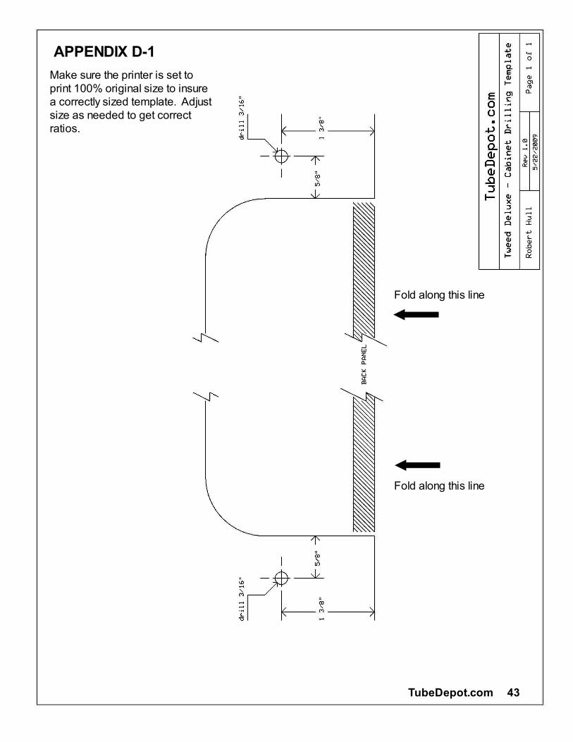
Make sure the printer is set to print 100% original size to insure a correctly sized template. Adjust size as needed to get correct ratios.
APPENDIX D-1
Fold along this line
Fold along this line
TubeDepot.com 43
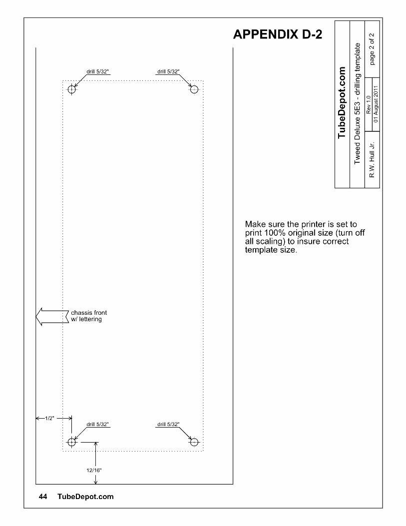

Test EquipmentLoad Box
I designed the following load box to be used between an amplifier and a speaker. The values are set for a speaker impedance of 8 ohms and an amplifier wattage of no more than 20W.
I've listed several different resistor value sets to choose from based on how much signal power you want making its way to the speaker.
I recommend building everything inside a small metal box. it is important to mount the resistors firmly against the sides of the box. When the load box is in operation, the resistors will get very hot and the heat will be properly dissipated when in contact with the metal sides. To improve this heat transfer, the resistors can be epoxied to the sides of the box.
Power toSpeaker Approximate R1 R1 R2 R2(15W source) Attenuation value wattage value wattage
10 watts - 2db 1.5 ohms 5W 36 ohms 5W7.3 watts - 3db 2.4 ohms 10W 18 ohms 10W5.2 watts - 5db 3.3 ohms 15W 12 ohms 10W3.8 watts - 6db 4.0 ohms 15W 8 ohms 10W1.9 watts - 9db 5.1 ohms 25W 4.7 ohms 10W0.9 watts - 12db 6.2 ohms 25W 3.9 ohms 5W
These resistors can be found from various electronic suppliers. Suppliers such as:
Mouser.comJameco.comDigikey.com
E Appendix E