Leak Reduction Best Practices: Charge Your Bottom Line, Not
55
Transcript of Leak Reduction Best Practices: Charge Your Bottom Line, Not


Leak Reduction Best Practices:
Charge Your Bottom Line, Not
Your Refrigeration System
By: Cliff Timko of Giant Eagle
And
Jonathan Perry of
Farm Fresh, a division of Supervalu

GreenChill &Farm Fresh
Presented by: Jon Perry
Director of Maintenance
and Energy
Farm Fresh: Leak Reduction
Best Practices using
Hydrogen
By: Jonathan Perry
Director of Energy and Maintenance

Hydrogen Leak Detection
Hydrogen Leak
Detection is similar to
electronic refrigerant
leak detection, only
the gas used as a
tracer gas has a
component of pure
hydrogen

Hydrostar for Leak Detection
• Pure Hydrogen is explosive,
Concentrations of 5% or less are not
• “Hydrostar” is a mix of 95% dry nitrogen
and 5% dry hydrogen
• It comes with a dryness of 1-2 ppm of
moisture
• It is ISO 140001 and ISO 10156 (meaning
it is Green and Safe)

Why use Hydrogen as a tracer gas?
• Traditional installations do not remain
leak tight over time, costing refrigerant
• New construction of non-traditional
systems are significantly higher cost
• Traditional systems can be the most
energy efficient if we can keep them leak
tight.
• Technicians are already trained to
service the existing fleet of supermarkets

Relative Leak Detection

Relative Leak Detection
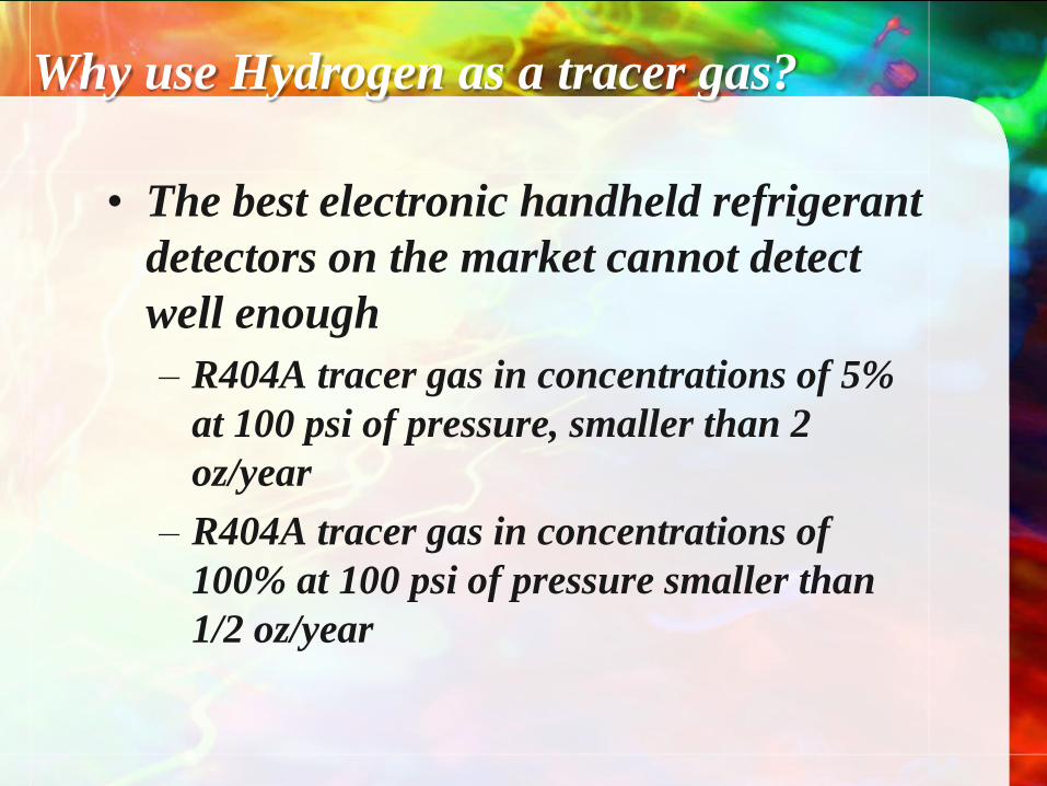
Why use Hydrogen as a tracer gas?
• The best electronic handheld refrigerant
detectors on the market cannot detect
well enough
– R404A tracer gas in concentrations of 5%
at 100 psi of pressure, smaller than 2
oz/year
– R404A tracer gas in concentrations of
100% at 100 psi of pressure smaller than
1/2 oz/year
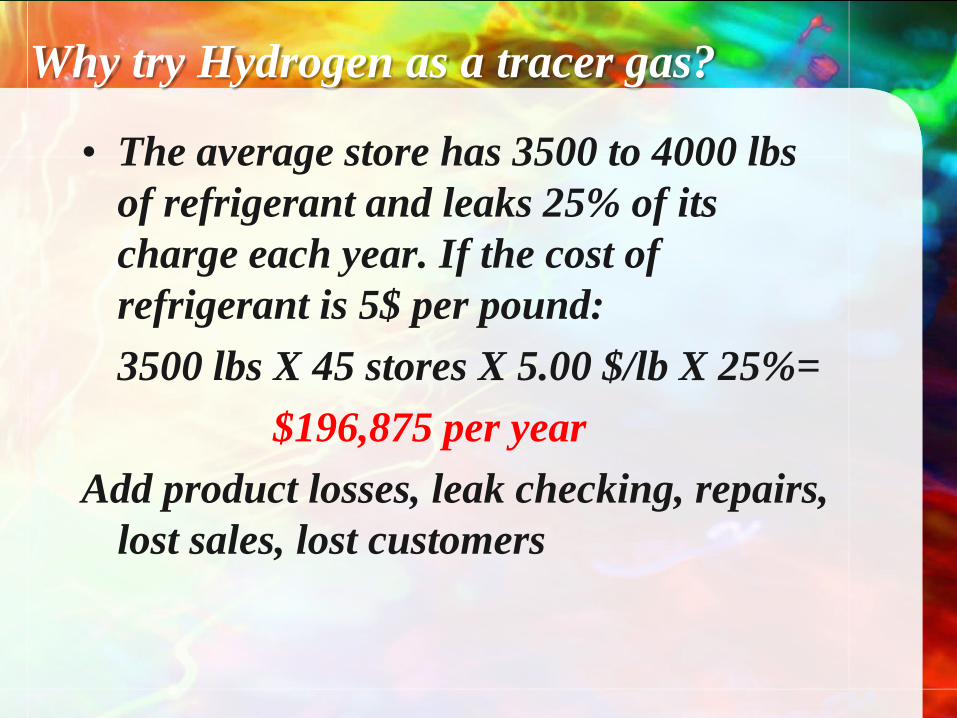
Why try Hydrogen as a tracer gas?
• The average store has 3500 to 4000 lbs
of refrigerant and leaks 25% of its
charge each year. If the cost of
refrigerant is 5$ per pound:
3500 lbs X 45 stores X 5.00 $/lb X 25%=
$196,875 per year
Add product losses, leak checking, repairs,
lost sales, lost customers

What is the cost?
• Hydrogen leak detection equipment can be
$5,000 to $15,000 per unit
• The gas is roughly 2 times the cost of dry
nitrogen
• Handheld electronic refrigerant leak
detectors can easily be found for around
$300
• Labor is essentially the same for a pressure
test
• Risk is higher with damaging equipment

How well does it work?
• Our first tested store was put to 300 psi of
Nitrogen for 60 hours and did not lose 1 psi of
pressure.
• With 125 psi of Hydrostar 8 small leaks were
found (3 factory solder joints, 2 field solder
joints, 3 flare nut fittings on pressure switches
and oil lines)
• We achieved the lowest microns I had witnessed
on a large system 125 microns after 24 hours.
• We used the most sensitive settings of hydrogen
detector

How well does it work?
• All of the leaks ranged from 1 x 10⁻⁵ down
to 1 x 10 -7.
• One of them was so noticeable with a
bubble test, I could not believe the test. I
had that compressor valved off from the
system, re-pressurized with nitrogen, and
R22 to recreate the original test leak. After
bubble testing the same leak for 15
minutes a tiny bubble slowly appeared.
• These are leaks that would not leak 1 oz.
of refrigerant in more than 20 years

Large Leaks Start Out Small

How well does it work?
• We refrigerant leak tested an existing lineup
in preparation to installing an additional
new case the following day.
• Upon installation of the new case, there
were pinhole leaks found in one of the
existing cases that did not pick up with the
refrigerant leak detector. The pinhole leaks
showed up immediately with hydrogen leak
detector.

How well does it work?
• There are many examples like this
• However, the best proof is we have not
had a leak on any system that we have
tested with hydrostar to 300 psi and pulled
vacuum.
• We are now consistently getting below 100
microns
How well does it work?
• Our first store hydrogen leak tested store
was opened May 7th 2008
• Since this store we have done 3 other total
gut remodels.
• Originally we had only one hydrogen
detector
• We had logistic problems with only 1
detector and could not test a lot of work
• We now have 3 leak detectors and require
all new systems to be hydrogen tested
• We still have some issues

Trying to improve the system
• I wanted to see what was feasible for
pulling vacuums.
• I wanted to create a super tight typical
reference system and find out how long it
should take to pull vacuum
• I wanted to dispel or prove myths about
vacuums
– One being you can’t pull a good vacuum on
old systems with oil present
– One being that you can pull a vacuum too fast
with an oversized vacuum pump
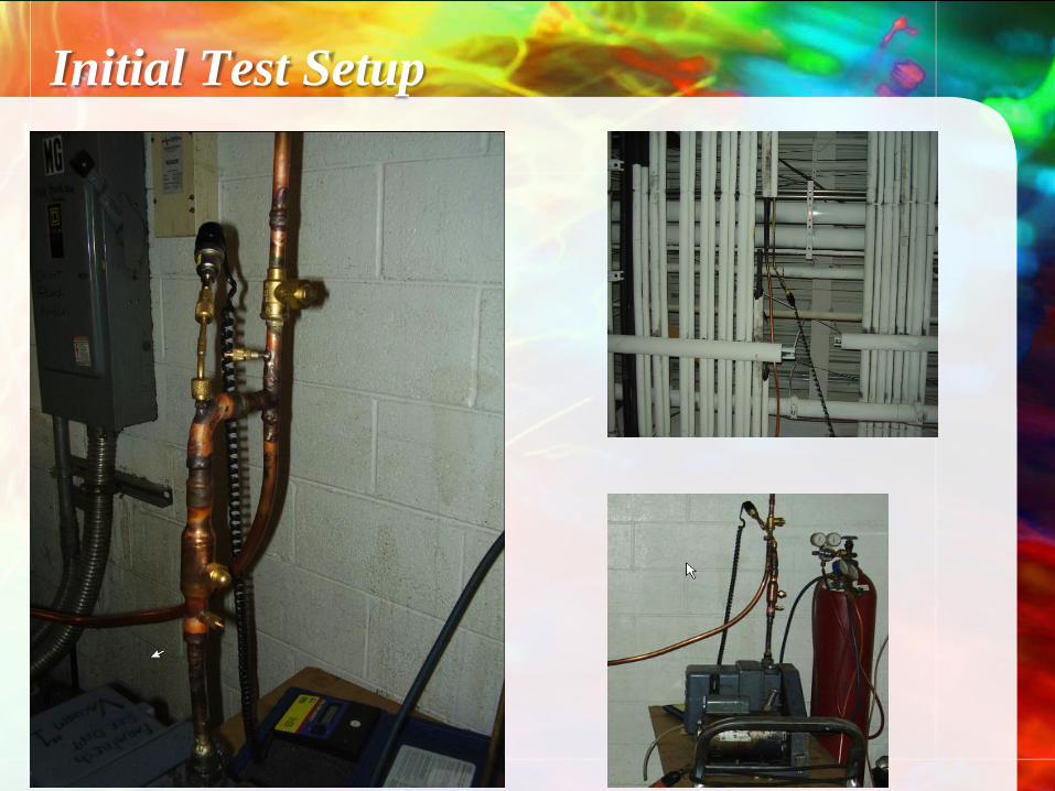
Initial Test Setup

Initial Test Setup
• 200 feet of suction 1-3/8”, 10 feet 7/8”
risers and ½” liquid line piping with 2
Dairy Cooler evaporator coils (Bohn
Model:ADT208)

Initial Test Setup
• We pressurized the system to 300 psi and
let hold for 48 hours with taps on suction
and liquid sides.
– The readings were dead on after 24 hours.
– At 48 hours we could tell there was almost
300 psi, but there was a slight hair difference
• We then leak checked with the Hydrogen
detector and found 3 leaks
– Both TXV packing nuts
– One suction riser had a hairline factory defect

A Note on pressure readings
• We no longer allow gauge manifolds
to be used for pressure testing
• We require stub gauges to be installed
on suction lines and liquid lines to
prove pressure throughout the system.
– Some txvs limit pressure that can flow
through them. So, we require both lines.
• We do not allow them to be taken off
during the test.
• We require the original reading to be
written in permanent ink on the pipe
next to the gauges

The Suction Riser of the Leaking
Evaporator Pressurized to 300 psi
Hydrostar vs. R22 & N2

Results of the test system
• We found that using hydrogen allowed us to
more consistently find all the leaks
• We were able to pull the test system consistently
below 10 microns
• We were able to get 3 different Ritchie micron
gauges to readings of zero and have them
remain at zero for 4 to 5 minutes, maintaining
microns as low as 20 microns for over a week
• Note: the system was 15 years old, R22 with
mineral oil. We on purpose heated the oil in the
system to burn it.

New Pressure and Vacuum Procedure
• Use a “dynamic flow” manifold set up
• Verify the pump, oil, and micron gauges to start
• Solder in the manifold with all associated
gauges before starting pressurization
• Use hydrostar and hydrogen leak testing
equipment to test the entire system at full
pressure
• Use as close to a “dynamic flow” hydrostar
purge as sensible.
• Pull the vacuum from the suction line to the far
end of the liquid line in one direction
• Repeat purge until the vacuum is achieved
New Vacuum Procedure
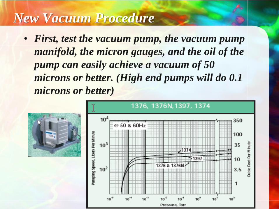
• First, test the vacuum pump, the vacuum pump
manifold, the micron gauges, and the oil of the
pump can easily achieve a vacuum of 50
microns or better. (High end pumps will do 0.1
microns or better)
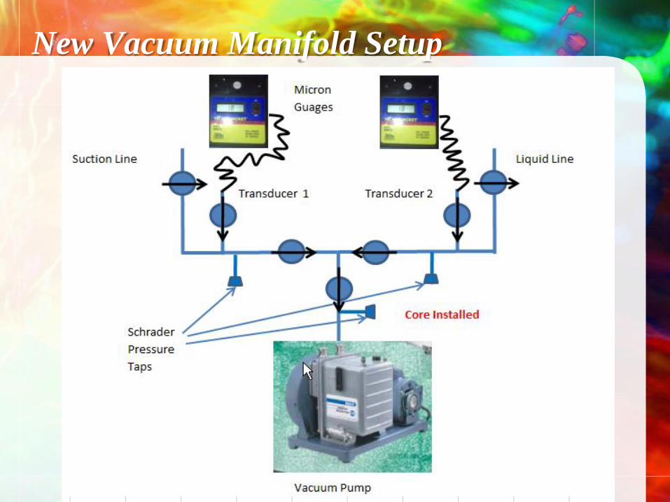
New Vacuum Manifold Setup

New Vacuum Procedure
• Before applying any pressure, remove the
Schrader core just before the vacuum pump.
Shut the ball valve closest to the pump and at
each micron gauge.

New Vacuum Procedure
• We no longer break vacuums in the traditional
method. We now break vacuum with what we term
“dynamic flow”.
• Charge the system from the
liquid line side
• Keep the pump valved off
• Keep micron gauges valved
off, but attached permanently
• Shut liquid line off from pump

New Vacuum Procedure • During this time the micron gauges should be reading
the low microns from the pump test and they are not
exposed to the pressure.
• Pressure test the entire system to a pressure of 50-100
psi Hydrostar, including the vacuum pump manifold.
(Make sure to remove core of the Schrader cap at
vacuum pump to not blow up the pump)
• If no huge leaks are found go to max pressure. (We
are typically going to 300 psi.) Keep the Hydrostar
fully connected and leak check it.
• Length of time depends on the job. We do 1 hour
minimum and long enough to leak check entire
system

New Vacuum Procedure
• Once the test has held at least 1 hour and no leaks
were found on the entire system the pressure test is
done. (longer is better)
• Crack the ball valve at the vacuum pump to relieve
the pressure out the open Schrader core
• This achieves a one direction flush from the furthest
point of the system on the liquid line towards the
vacuum pump through the entire system.
• Replace the core and cap the opened Schrader valve
• Reduce the hydrostar regulator to 2 psi or lower
• You now have a system full of hydrostar at
atmospheric pressure ready to pull a vacuum.

Dynamic Flow
• The hydrostar can flow
up the liquid line
through the system
valves and down the
suction line to the
vacuum pump in one
direction.

Dynamic Flow
• Now open the pump to the suction side of the
system. Having all valves on the system wide
open. The valve to the liquid side of the vacuum
manifold should remain closed so the pump does
not pull through the liquid line during any of the
dynamic flow portion of the vacuum.

New Vacuum Procedure
• The system should rapidly pull to 1,000 microns or
better for a single circuit. Both gauges should read
below 5,000 microns
• To break open and close the Hydrostar valve quickly
• Watch the micron gauges. The liquid micron gauge
will shoot up to about 20,000 to 80,000 and the
suction will come up to a few thousand. In a matter
of a minute or two you should be back to your
earlier readings
• Repeat this about 5 times or more
• Disconnect the Hydrostar with it flowing so no
atmosphere enters the system

New Vacuum Procedure
• Let the system pull either until you have the
desired micron reading. Valve off the system and
let it stabilize.
• I do recommend cycling solenoids and turning
all valves if it is possible during deep vacuum
• You can also open up the vacuum manifold to
both sides after a reasonable time to pull less
restricted once you have done the breaking
completely, but when you read your microns you
have to remember you will be reading close to
the pump and not the far end of the system

Logic of the New Vacuum Procedure
It is like swimming in a lake versus a river. If you try
to swim to the edge of a raging river the current
sweeps you to towards the ocean, but swimming to
the edge of a lake is not difficult.
Breaking a system the old way is the lake concept
there is not a push to the vacuum pump. Also, you
are constantly contaminating the system if you
remove the micron gauges.

Hydrogen may be Greener
• When we use Hydrostar we have eliminated the
use of diminimus gas (we do not use any
refrigerant for leak testing)
• Also, we are experiencing vacuum pump oil
lasting many jobs. (In my testing of the test
system over 4 weeks I never had to change the
oil.)

2006 FMI Techical Slides
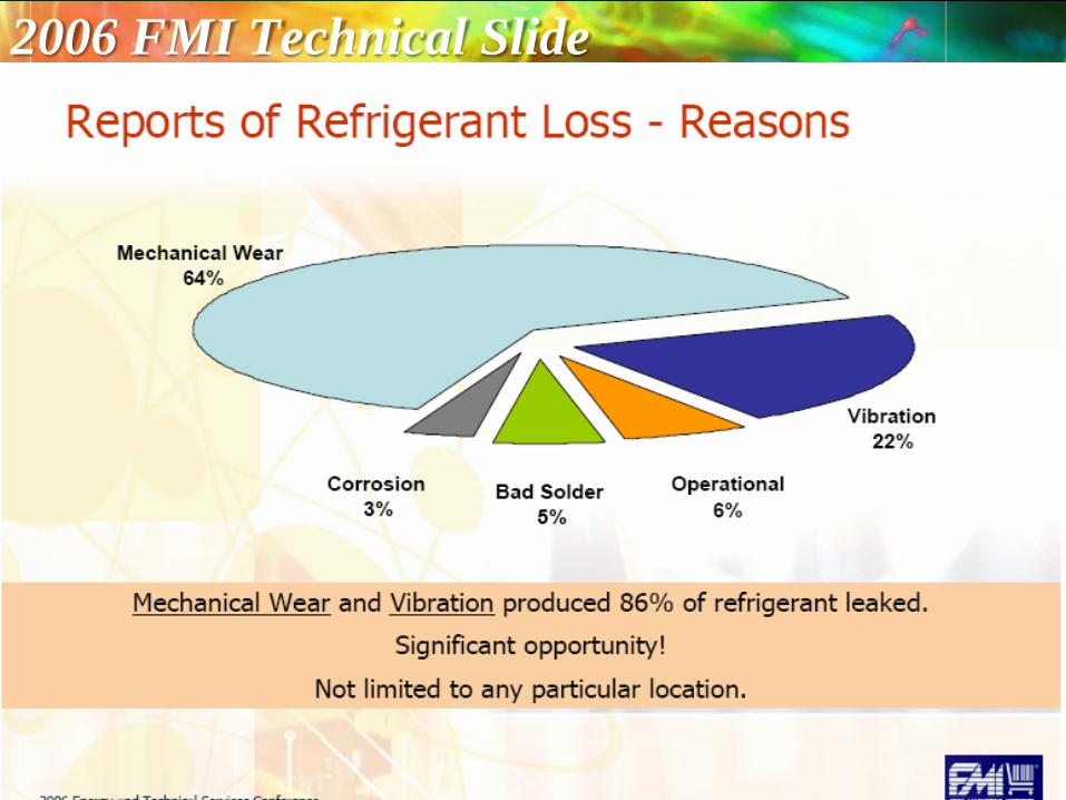
2006 FMI Technical Slide

2006 FMI Technical Slide

New Store Design Points and Retrofits
• Motor rooms are built on solid ground
• Contained Motor Room
• Infrared Leak Detection in the motor room,
and we are experimenting on the sales floor
• All mechanical areas are alarmed for entry
• No Schraders outside the motor room
• Remote Analog liquid level sensors
• Better piping support
• Reduced Charge
• Non ODS / Low GWP

New Store Design (continued)
• Motor rooms are on the ground on solid
concrete to stop vibration
• They are air conditioned. This enables
them to be a confined space for
improved leak detection

Motor Room Exhaust only runs in
Emergency
• Eliminates 20,000 CFM of air moving
through to cool the equipment.
– This eliminates dirt and dust accumulations
– Allows a technician to keep the motor room
spotless and easily check for refrigerant leaks

New Store Design and Reftrofits
• Spacious and Clear
• They are kept Clean
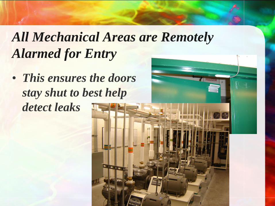
All Mechanical Areas are Remotely
Alarmed for Entry
• This ensures the doors
stay shut to best help
detect leaks

Better Pipe Support in the Overhead
• Insugaurd

Superior Case Line Supports

Assisting with Leak Checking
• Live As-builts
– Access to building automation on a computer
– There are live circuit drawings (virtual walk-
through drawings of electrical, mechanical,
plumbing etc.)
– Site specific information specifically level
indicators and leak detection sensors


Reduced Charge
• One central system with
loop piping
• One Surge receiver / Roof
mounted
• Extreme Sub-cooling
reduces liquid line sizes
• Hydronic heat reclaim with
flat plate heat exchangers
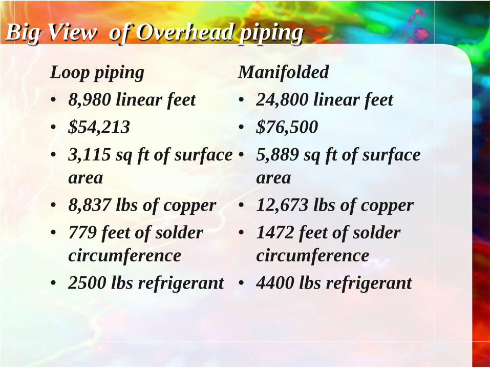
Big View of Overhead piping
Loop piping
• 8,980 linear feet
• $54,213
• 3,115 sq ft of surface
area
• 8,837 lbs of copper
• 779 feet of solder
circumference
• 2500 lbs refrigerant
Manifolded
• 24,800 linear feet
• $76,500
• 5,889 sq ft of surface
area
• 12,673 lbs of copper
• 1472 feet of solder
circumference
• 4400 lbs refrigerant

Farm Fresh Joined Green Chill
• Announcement March 26, 2008
• After that we worked on the Best
Practices Guidelines for Refrigeration
Installation

Other …
• We have devoted more technicians to leak checking
than ever
• A greater support and awarenes with upper
management
– I personally am reviewing all vacuum tests
– We do not do overnight case turn overs unless I
have certified the microns
• If a leak is not found we move to pressure testing the
entire rack with in a few days
• Infrared leak alarms are responded to immediately
(about 1 hour)

Where are we headed?
• We are watching secondary systems and CO2
• Removal of all Schrader's outside of motor room
• Better partnerships with suppliers focused on
reducing leaks creating improved equipment
(Case piping)
• We continue to reduce our charge (last store
1800 lbs for all equipment including HVAC)
• Improved installation techniques
– Higher pressure testing for longer periods
– Lower vacuums for longer periods
– Hydrogen leak testing is now standard practice

Thank you